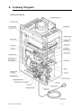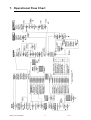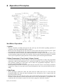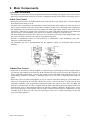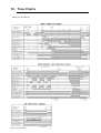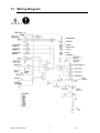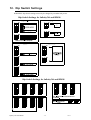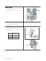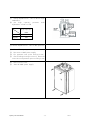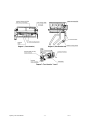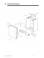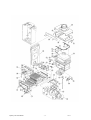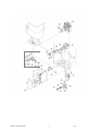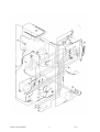
1
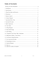
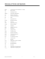
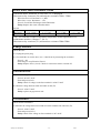
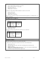
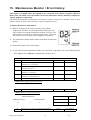
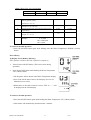
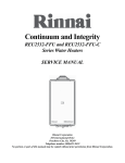
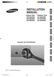
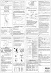
INFINITY 26i and HD50i
SERVICE MANUAL
Infinity High Capacity Continuous Flow Gas Hot Water System
The Rinnai Infinity 26i and
Heavy Duty 50i water heater,
when correctly installed, comply
with the requirements of the
United Kingdom Water Regulations / Byelaws (Scotland).
These Products can be found
listed in the Water Fittings and
Materials Directory.
The Rinnai Infinity 26i water heater
is CE Marked for UK and Ireland as
allowed by Technigas of Belgium.
Certificate number E0716/5360
ID number 0461BO0739
Date of Issue 28 July 2003
Quality System Standard
ISO 9001 - 1994
The Design, Development, and Manufacture of Gas Water Heating Appliances
done under Rinnai’s Quality Management System is certified under the Quality
Management System Standard ISO 9001.
Registration Number JQ0003D
Registered since: February 1994
Certified by Japan Gas Appliances Inspection Association.
Produced by Rinnai Technical Services Department
August 2004 - Issue 1.
No portion or part of this manual may be copied without prior permission from Rinnai U.K.
Rinnai U.K. reserves the right to make modifications and change specifications without notice.
WARNING
Failure to comply with these instructions may result in serious personal injury or damage to the
appliance.
ALL WIRING INSIDE THIS APPLIANCE MAY BE AT 230 VOLTS POTENTIAL
ALL SERVICE WORK MUST BE CARRIED OUT BY AN AUTHORISED PERSON.
DO NOT TEST FOR GAS ESCAPES WITH AN OPEN FLAME
This manual has been published by Rinnai U.K. Technical Services. While many individuals
have contributed to this publication, it will be successful only if you - the reader and customer find it useful. We would like to extend an invitation to users of this manual to make contact with
us, as your feedback and suggestions are valuable resources for us to include as improvements.
Rinnai are constantly working toward supply improved appliances as well as information, and
specifications may be subject to alteration at any time.
Issue No1
Table of Contents
Glossary of Terms and Symbols .................................................................................. iv
1. Introduction ................................................................................................................ 1
2. Specifications ............................................................................................................. 2
3. Water Flow Rates and Pressures ................................................................................ 4
4. Dimensions ................................................................................................................ 8
5. Remote Controls ........................................................................................................ 9
6. Cutaway Diagram .................................................................................................... 13
7. Operational Flow Chart ........................................................................................... 14
8. Operation Principles ................................................................................................ 15
9. Main Components .................................................................................................... 16
10. Time Charts ............................................................................................................ 18
11. Wiring Diagram ..................................................................................................... 19
12. Dip Switch Settings ............................................................................................... 20
13. Fault Finding .......................................................................................................... 21
14. Component Circuit Value Tabl.e / and checks........................................................ 23
15. Maintenance Monitor / Error History ................................................................... 31
16. Gas Pressure Setting Procedure ............................................................................ 33
17. Gas Conversion Procedure .................................................................................... 35
18. Dismantling for Service ........................................................................................ 44
19. Exploded Diagram ................................................................................................ 50
20. Parts List ............................................................................................................... 54
21. SERVICE CONTACT POINTS .......................................................................... 58
Infinity REU-V2632FFU
/ HD200I REU-V2632FFUC
Infinity
26i and HD50i
- iii -
Issue 1 - 8/09/03 ©Rinnai
Glossary of Terms and Symbols
dB(A)
-
sound pressure level in decibels, “A” range
DC
-
direct current
AC
-
alternating current
WFCD
-
water flow control device
FB
-
feedback information
FF
-
feedforward information
Hz
-
Hertz
IC
-
integrated circuit
kcal/h
-
kilocalorie per hour
kW
-
kilowatts
LED
-
light emitting diode
L/min
-
Litres per minute
mA
-
milliamps
mbar
-
millibars of pressure
mm
-
millimetres
bar
-
gauge pressure
OHS
-
overheat switch
PCB
-
printed circuit board
CPU
-
central processing unit
POT
-
potentiometer
rpm
-
revolutions per minute
SV
-
solenoid valve
ø
-
diameter
' oC
-
temperature rise above ambient
POV
-
modulating valve
TE
-
thermal efficiency
TH
-
thermistor
TIN
-
temperature of incoming water
TOUT
-
temperature of outgoing water
Infinity REU-V2632FFU
/ HD200I REU-V2632FFUC
Infinity
26i and HD50i
- iv -
Issue 1 - 8/09/03 ©Rinnai
1. Introduction
The Rinnai Infinity hot water units represents the latest technology in continuous flow, temperature
controlled hot water.
Features
• The Infinity 26i and HD50i NEVER RUN OUT of hot water. Whilst electricity, water and gas
supplies are connected, hot water is available whenever hot water taps are open.
• Built into the main micro-processor is the facility to LIMIT THE MAXIMUM TEMPERATURE of
the hot water supplied. The water temperature may be limited to various maximum temperatures. This
is particularly useful when the hot water unit is installed where young children or the infirm may be
using the hot water. The Infinity is delivered with a maximum preset temperature of 55 q C and the
HD50i at 65° C. If required, the temperature limits can be changed by a service technician. For
further information, please contact Rinnai.
• The Infinity is a power flued appliance. It is COMPACT, saving both floor and wall space.
• The temperature of outgoing hot water is CONSTANTLY MONITORED by a BUILT-IN SENSOR. If
the temperature of the outgoing hot water rises to more than 3 q C above the selected temperature
shown on the Digital Monitor (or the pre-set limit when Remote Controls are not fitted), the burner will
automatically go out. The burner will ignite again once the outgoing hot water temperature falls below
the temperature shown on the Digital Monitor (or the pre-set limit).
• The burner lights automatically when the hot water tap is opened, and goes out when the tap is closed.
IGNITION IS ELECTRONIC, therefore there is not pilot light. When the hot water tap is off, no gas is
used.
• ‘Deluxe’ or ‘Standard’ Remote Controllers are available as an optional extra. Depending on the models
chosen, these offer the following additional features :
- Bath fill function
- Voice Prompting
- Localised Temperature Control for up to four controllers
- Clock
• Temperatures selected at the controllers are retained in the SYSTEM MEMORY.
• Operating NOISE LEVEL IS VERY LOW.
• ERROR MESSAGES ARE DISPLAYED on the Remote Controllers, assisting with service.
Infinity REU-V2632FFU
/ HD200I REU-V2632FFUC
Infinity
26i and HD50i
-1-
Issue 1 - 8/09/03 ©Rinnai
2. Specifications
Model No.
Type of Appliance
Operation
Flue System
Installation
Available Default Temperatures (Note 1):
(without Remote Controllers)
Temperature Range (with Remote Controllers)
Width
Height
Depth
Dimensions (mm)
Weight (Kg)
Connections
Gas
Cold Water Supply
Hot Water Supply
Ignition System
Max. / Min. Gas
Natural Gas
Consumption
Propane Gas
Hot Water Delivery Capacity Max.
Noise level
Thermal Efficiency
NOXaf
Minimum Operating Water Flow:
Minimum Operating Pressure (Note 2):
Maximum Operating Water flow
Nominal Operat- Less than 60°C
ing Pressure
Greater than or equal to 60°C
Infinity Unit
Power Supply
Remote Control (optional)
Water temperature control
Water flow
control
Flame Failure
Boil dry
Remaining Flame (OHS)
Over temperature
Safety Device
Fusible link
Pressure relief valve
Combustion fan rpm check
Over current
Remote
Kitchen
Controllers
Bathroom
(optional)
Second Bathroom
Third Bathroom
Infinity 26i and HD50i
Temp.controlled continuous Flow Gas Hot Water Unit
With/without remote controls, mounted in Kitchen, bathroom, etc.
Room Sealed - Forced Draught Flue
Internally mounted (Indoor Only)
40º C, 43º C, 50º C, 55º C, 60º C, 65º C, 75º C, 85º C
(set by combination of Dip switches on PCB)
Kitchen controller
: 37 ~ 55º C
Bathroom controller
: 37 ~ 50º C
350
600
224
22
3/4 in. BSP
3/4 in. BSP
3/4 in. BSP
Direct Electronic Ignition
54 -- 4.4 kW
54 -- 4.4 kW
26 to 32 L/min.
49 dB(A)
87%
55 ppm Max.
2.4 L/min.
1.8 bar
32 L/min.
1.4 bar
2.0 ~ 10.0 bar
AC 230 Volts (50 Hz)
DC 12 Volts (Digital)
Simulation feedforward and feedback
Electronic Water flow sensor, flow control & heat exchanger
by-pass flow control.
Flame rod
Water flow sensor
97º C bi-metal switch
95º C lockout thermistor
129º C Thermal Fuse
Opens 20.6 bar, closes 14.7 bar
Integrated circuit system
Glass fuse (3 Amp).
MC91-1A or MC-70-2A
MC91-1A or BC-70-2A
MC91-1A or BC-70-2A
MC91-1A
Remote Controller Cable (Optional)
Two core sheathed (double insulated) flex with min.cross-sectional area of 0.5 mm²
Normal
Electrical
Consumption
Standby
Manifold Electronic Control System (Optional)
80W
7.5 W (with 1 Remote Control)
MSA-2M, MSA-2S
Note 1: The default factory setting is 55ºC for the Infinity26i, and 65°C for HD50i. The unit can be ordered
from Rinnai to be pre-set to any of the other temperatures listed. The unit can be pre-set to any of the
temperatures listed by a suitably qualified person.
Controllers are available with default temperatures up to 75º C. When fitted with controllers, only
temperatures not exceeding the default temperatures can be selected. When fitted without controllers, the
unit will deliver water at the default temperature. Controllers are not available with 85° C settings.
Note 2: Unit will operate at lower pressures but the maximum rated flow of 32L/min. will not be achieved.
Infinity REU-V2632FFU
/ HD200I REU-V2632FFUC
Infinity
26i and HD50i
-2-
Issue 1 - 8/09/03 ©Rinnai
Sensors and Safety Devices
• Heat Exchanger Thermistor: Measures hot water temperature at heat exchanger outlet. If water
temperature reaches a predetermined limit, gas supply is stopped.
• Hot Water Delivery Thermistor: Measures hot water temperature at the outlet valve (i.e. the ‘mixed’
temperature).
• Flame Rod: Monitors combustion characteristics inside the combustion chamber. If the flame fails, gas
supply is stopped.
• Overheat Switch: Situated on the heat exchanger, gas supply is stopped when water temperature
reaches 97ºC for a number of seconds.
• Fusible Link: Situated on the heat exchanger, electrical power supply is stopped if the temperature
exceeds 129ºC.
• Water Pressure Relief Valve: Safeguards the water circuit against excessive inlet pressure. Opens at
20.6 bar, closes at 14.7 bar.
• Electrical Fuse: (3A glass fuse) prevents against over-current.
Surge Protector: prevents against over-current.
• Boil Dry Prevention: If water flow sensor detects no flow, gas supply is stopped.
• Combustion Fan Speed Sensor: In case of combustion fan defect (no rotation of fan) gas supply is
stopped.
• Temperature Cutout: If the delivered hot water temperature rises above the required delivery
temperature for a number of seconds, the gas supply is stopped.
Combustion Specifications
Gas Type
Natural
Propane
Injector
Size (mm)
Upper /
Lower
1.00
1.7
0.75
1.15
Nominal TPP (mbar) * *
Gas Input (kW)
Low
High
Low
High
1.9
8.5
4.4
54
2.3
10.8
4.4
54
* * The TPP is measured with the cover ‘off’ the appliance at the regulator test point with supply pressures
of 20 mbar (NG) and 37 mbar (Propane).
Infinity REU-V2632FFU
/ HD200I REU-V2632FFUC
Infinity
26i and HD50i
-3-
Issue 1 - 8/09/03 ©Rinnai
3. Water Flow Rates and Pressures
Water Flows
Table 1 shows unmixed and mixed water flow rates and approximate gas consumptions for various
temperature rises. The unmixed flow rates are the flow rates available at the given temperature rise directly
at the outlet of the water heater. The mixed water flow rates are available at the given temperature rise by
mixing hot water from the outlet of the water heater with cold water from the mains supply.
Water Flows can also be calculated by the following formula:
M = 60 x ( Q / C x ' T )
Where M = Water flow rate in litres/minute. If M is dto 26, the water is unmixed. If M is !, the water
is mixed.
Q = Heat energy output in kW = 47kW for the Infinity 26i and HD50i
C = Specific heat of water = 4.2KJ/Kg q C. C does not change for the purpose of this calculation.
' T = Temperature rise required ( q C)
Example:
What is the flow rate available with an incoming water temperature of 10 q C and a required temperature of
20 q C?
' T = 20 - 10 = 10 q C
Q = 47
C = 4.2
M = 60 x ( 47 / (4.2 x 10) ) = 67 l/min. Since 67 is greater than 26 this flow rate is mixed. This result
corresponds with the value in Table 1.
Table 1: Approximate Water Flows & Gas Usage - Rinnai Infinity 26i and HD50i - Preset Table
Infinity REU-V2632FFU
/ HD200I REU-V2632FFUC
Infinity
26i and HD50i
-4-
Issue 1 - 8/09/03 ©Rinnai
Infinity REU-V2632FFU
/ HD200I REU-V2632FFUC
Infinity
26i and HD50i
-5-
Models (Preset temps
less than 60 C)
4.4-54
Temp Rise
(º C)
Approx.
Min / Max
Gas Input
kW
Infinity 26 i and HD 50i
Infinity 26 i and HD 50i
4.4-54
Models (Preset temps
less than 60 C)
Infinity 26 i and HD 50i
Temp Rise
(º C)
Approx.
Min / Max
Gas Input
kW
4.4-54
Models (Preset temps
less than 60 C)
4.4-54
Temp Rise
(º C)
Approx.
Min / Max
Gas Input
kW
Infinity 26 i and HD 50i
Models (Preset temps
less than 60 C)
Temp Rise
(º C)
Approx.
Min / Max
Gas Input
kW
0.17
L/sec
0.25
L/sec
0.44
L/sec
0.53
L/sec
10.2
L/min
15
L/min
26.4
L/min
32
L/min
612
L/hr
65
900
L/hr
45
1584
L/hr
25
1920
L/hr
5
0.19
Min Water
Pressure
bar
0.3
Min Water
Pressure
bar
1.0
Min Water
Pressure
bar
1.4
Min Water
Pressure
bar
54
Approx
Gas
Cons.
kW
54
Approx
Gas
Cons.
kW
54
Approx
Gas
Cons.
kW
13
Approx
Gas
Cons.
kW
0.16
L/sec
0.22
L/sec
0.37
L/sec
0.53
L/sec
9.6
L/min
13.2
L/min
22.2
L/min
32
L/min
576
L/hr
70
792
L/hr
50
1332
L/hr
30
1920
L/hr
10
0.18
Min Water
Pressure
bar
0.25
Min Water
Pressure
bar
0.65
Min Water
Pressure
bar
1.4
Min Water
Pressure
bar
54
Approx
Gas
Cons.
kW
54
Approx
Gas
Cons.
kW
54
Approx
Gas
Cons.
kW
26
Approx
Gas
Cons.
kW
0.15
L/sec
0.2
L/sec
0.32
L/sec
0.53
L/sec
9
L/min
12
L/min
19.2
L/min
32
L/min
540
L/hr
75
720
L/hr
55
1152
L/hr
35
1920
L/hr
15
0.17
Min Water
Pressure
bar
0.23
Min Water
Pressure
bar
0.5
Min Water
Pressure
bar
1.4
Min Water
Pressure
bar
54
Approx
Gas
Cons.
kW
54
Approx
Gas
Cons.
kW
54
Approx
Gas
Cons.
kW
39
Approx
Gas
Cons.
kW
0.14
L/sec
0.19
L/sec
0.28
L/sec
0.53
L/sec
8.4
L/min
11.4
L/min
16.8
L/min
32
L/min
504
L/hr
80
684
L/hr
60
1008
L/hr
40
1920
L/hr
20
0.16
Min Water
Pressure
bar
0.2
Min Water
Pressure
bar
0.4
Min Water
Pressure
bar
1.4
Min Water
Pressure
bar
54
Approx
Gas
Cons.
kW
54
Approx
Gas
Cons.
kW
54
Approx
Gas
Cons.
kW
52
Approx
Gas
Cons.
kW
Table 1. Approx. Water Flows & Gas Usage - Rinnai 26i and HD50i Preset Temp. Less than 60°C.
Issue 1 - 8/09/03 ©Rinnai
4.4-54
Infinity 26 i and HD 50i
Infinity REU-V2632FFU
/ HD200I REU-V2632FFUC
Infinity
26i and HD50i
4.4-54
-6-
4.4-54
Infinity 26 i and HD 50i
4.4-54
Models (Preset temps greater Temp Rise
(º C)
than or equal to
60 C)
Approx.
Min / Max
Gas Input
kW
Infinity 26 i and HD 50i
Models (Preset temps greater Temp Rise
than or equal to
(º C)
60 C)
Approx.
Min / Max
Gas Input
kW
Infinity 26 i and HD 50i
Approx.
Min / Max
Gas Input
kW
Models (Preset temps greater Temp Rise
than or equal to
(º C)
60 C)
Temp Rise
(º C)
Approx.
Min / Max
Gas Input
kW
Models (Preset temps greater
than or equal to
60 C)
0.17
L/sec
0.25
L/sec
0.4
L/sec
0.4
L/sec
10.2
L/min
15
L/min
24
L/min
24
L/min
612
L/hr
65
900
L/hr
45
1440
L/hr
25
1440
L/hr
5
0.3
Min Water
Pressure
bar
0.5
Min Water
Pressure
bar
2.0
Min Water
Pressure
bar
2.0
Min Water
Pressure
bar
54
Approx
Gas
Cons.
kW
54
Approx
Gas
Cons.
kW
50
Approx
Gas
Cons.
kW
10
Approx
Gas
Cons.
kW
0.16
L/sec
0.22
L/sec
0.37
L/sec
0.4
L/sec
9.6
L/min
13.2
L/min
22.2
L/min
24
L/min
576
L/hr
70
792
L/hr
50
1332
L/hr
30
1440
L/hr
10
0.3
Min Water
Pressure
bar
0.4
Min Water
Pressure
bar
1.1
Min Water
Pressure
bar
2.0
Min Water
Pressure
bar
54
Approx
Gas
Cons.
kW
54
Approx
Gas
Cons.
kW
54
Approx
Gas
Cons.
kW
20
Approx
Gas
Cons.
kW
0.15
L/sec
0.2
L/sec
0.32
L/sec
0.4
L/sec
9
L/min
12
L/min
19.2
L/min
24
L/min
540
L/hr
75
720
L/hr
55
1152
L/hr
35
1440
L/hr
15
0.27
Min Water
Pressure
bar
0.4
Min Water
Pressure
bar
0.8
Min Water
Pressure
bar
2.0
Min Water
Pressure
bar
54
Approx
Gas
Cons.
kW
54
Approx
Gas
Cons.
kW
54
Approx
Gas
Cons.
kW
30
Approx
Gas
Cons.
kW
0.14
L/sec
0.19
L/sec
0.28
L/sec
0.4
L/sec
8.4
L/min
11.4
L/min
16.8
L/min
24
L/min
504
L/hr
80
684
L/hr
60
1008
L/hr
40
1440
L/hr
20
0.25
Min Water
Pressure
bar
0.3
Min Water
Pressure
bar
0.6
Min Water
Pressure
bar
2.0
Min Water
Pressure
bar
54
Approx
Gas
Cons.
kW
54
Approx
Gas
Cons.
kW
54
Approx
Gas
Cons.
kW
40
Approx
Gas
Cons.
kW
Approx.Water Flows & Gas Usage -Rinnai Infinity26i and 50i Preset Temp.Greater than or equal to 60°C
Issue 1 - 8/09/03 ©Rinnai
Water Pressure
The water pressure vs flow characteristics are as follows:
WATER PRESSURE/FLOW RATE
35
INFINITY 26i AND HD50i웛37ദ-55ദ
30
WATER FLOW RATE (L/min)
25
INFINITY 26i AND HD50i:60ദ+LJKHU
20
15
10
5
0
1.0
Infinity REU-V2632FFU
/ HD200I REU-V2632FFUC
Infinity
26i and HD50i
2.0
3.0
WATER PRESSURE(bar)
-7-
4.0
Issue 1 - 8/09/03 ©Rinnai
4. Dimensions
Infinity REU-V2632FFU
/ HD200I REU-V2632FFUC
Infinity
26i and HD50i
-8-
Issue 1 - 8/09/03 ©Rinnai
5. Remote Controls
Remote Controls
Remote Controllers are an optional extra. 'Standard' and 'Deluxe' controllers can be
fitted.
Standard controllers allow temperature selection only. Deluxe controllers have
temperature selection, bath-fill and voice prompting functions. For detailed
information regarding controller operation refer to the 'How to use your water
heater' booklet supplied with the appliance. Other manufacturers' controllers are
NOT compatible with this appliance.
120
MC-91-1A
Standard Controller (Model MC-91)
90
20
Up to 4 Standard Controllers can be fitted to the appliance. They are normally
installed in the areas where the majority of hot water is used, for example, the
kitchen, bathroom, ensuite and laundry.
Deluxe Kitchen Remote Control (MC-70) and (BC-70A)
Deluxe controllers have 'Kitchen' (MC-70-2A) and 'Bathroom' (BC-70-2A) versions. 'Kitchen' controls are
intended for the Kitchen or other convenient area where the majority of hot water is used. Bathroom
Controllers are intended to be fitted in the bathroom or ensuite and allow the user to have a bath filled to
the required level and temperature automatically.
97
BC-70-2A
22
195
:
Up to three ‘Deluxe’ Controllers
can be connected
Kitchen
MC70-2A
MC70-2A
MC70-2A
MC70-2A
Bathroom
BC70-2A
BC70-2A
If a fourth Controller is required a ‘Standard’
Controller can be included
Ensuite
Kitchen
Bathroom
Ensuite
Laundry
BC70-2A
MC70-2A
MC70-2A
MC70-2A
MC70-2A
BC70-2A
BC70-2A
BC70-2A
MC91-1A
Positioning of Controllers
Controllers must be installed in shaded and clean locations. They should be fitted out of reach of children
(suggested height from floor at least 1500mm). Controllers are water resistant, however, durability is
improved when positioned outside the shower recess or at least 400mm above the highest part of a sink,
basin or bath.
Infinity REU-V2632FFU
/ HD200I REU-V2632FFUC
Infinity
26i and HD50i
-9-
Issue 1 - 8/09/03 ©Rinnai
DO NOT INSTALL THE CONTROLLERS
• NEAR A HEAT SOURCE, SUCH AS A COOK TOP, STOVE OR OVEN. HEAT, STEAM,
SMOKE AND HOT OIL MAY CAUSE DAMAGE
• IN DIRECT SUNLIGHT
• OUTDOORS UNLESS AN ENCLOSURE IS PROVIDED WHICH PROTECTS THE
CONTROLLER AGAINST SUNLIGHT AND DUST INGRESS.
• AGAINST A METAL WALL UNLESS THE WALL IS EARTHED IN ACCORDANCE
WITH CURRENT REGULATIONS.
Remote Controller Connection
Remote controls operate at extra low voltage (12 Volts DC) which is supplied from the appliance.
Controllers are supplied with 15 m of electrical cable. The cable wires for connection to the appliance are
fitted with spade terminals.
Extension cables are available from Rinnai. Alternatively, a two core sheathed (double insulated) flex with
minimum cross-sectional area of 0.5 mm² can be used. Maximum cable length is 50 m.
For connection refer to the “CONNECTING REMOTE CONTROL CABLES” section.
If the front cover of the appliance contains the following text install it in accordance with Diagram 1 below:
Water Heater and Controller installation configurations
50º C
H
O
T
C
O
L
D
KITCHEN
Temperature
controller
(optional)
LAUNDRY
Temperature
controller
(optional)
BATHROOM
Temperature
controller
(optional)
ENSUITE
Temperature
controller
(optional)
G
A
S
Diagram 1. Max. 50º C Appliance
If the front cover of the appliance does NOT contain the above text install it in accordance with Diagram 2:
H
O
T
C
O
L
D
Temperature
controller
(optional)
Temperature
controller
(optional)
Temperature
controller
(optional)
Temperature
controller
(optional)
KITCHEN
LAUNDRY
BATHROOM
ENSUITE
TLD
G
A
S
Diagram 2. Not a 50º C Appliance
Note: TLD = Temperature Limiting Device Recommended.
IMPORTANT: If the appliance is to deliver water primarily for the purposes of personal hygiene in an
early childhood centre, primary or secondary school, nursing home or similar facility for young, aged, sick
or disabled persons a Temperature Limiting Device (TLD), such as a Thermostatic Mixing Valve,
may be required even if the appliance is set to 50ºC or less. For these types of applications contact
Rinnai UK.
Infinity REU-V2632FFU
/ HD200I REU-V2632FFUC
Infinity
26i and HD50i
- 10 -
Issue 1 - 8/09/03 ©Rinnai
Connecting remote control cables
Do not attempt to connect the remote control cable terminals to the appliance with the power on.
RISK OF ELECTRICAL SHOCK.
Connecting One or Two Controllers
1. Isolate the power supply
2. Remove the front cover from the Appliance (4 screws) fig. 1.
3. Thread the cable(s) through the cable access hole at the base
of the appliance.
4. Connect the spade connectors to the terminals marked
"Remote Control" on the printed circuit board (fig. 2).
Polarity is not important. Either wire colour can be
connected to either terminal.
5. Replace cover of the Appliance. Ensure that the screw with
the star washer is placed at the bottom right hand corner for
earthing purposes.
fig.1
Connecting Three Controllers
6. Isolate the power supply
7. Remove the front cover from the Appliance (4 screws) fig.1.
8. Thread the cables through the cable access hole at the base of
the appliance.
9. Connect the 4 spade connectors to the terminals marked
"Remote Control" on the printed circuit board (fig. 2).
Polarity is not important. Either wire colour can be connected
to either terminal.
10.Replace cover of the Appliance. Ensure that the screw with
the star washer is placed at the bottom right hand corner for
earthing purposes.
fig.2
Connecting Four Controllers
New spade connectors
11.Isolate the power supply
12.Remove the front cover from the Appliance (4 screws) fig 1.
13.Cut the spade connectors from all four controller cables to be
connected to the appliance (8 spade connectors should be cut
off) and discard. Connect the wires from two cables and
terminate into two new spade connectors as shown in (fig. 3).
Cable
wires
Cable
wires
Repeat for the remaining two cables. Spade connectors are
available from your local electrical component retailer.
14.Thread the 4 cables through the cable access hole at the base
of the appliance. Connect the 4 spade connectors to the
terminals marked "Remote Control" on the printed circuit
board (fig 2). Polarity is not important. Either wire colour
can be connected to either terminal.
15.Replace cover of the Appliance. Ensure that the screw with
the star washer is placed at the bottom right hand corner for
earthing purposes.
Remote control cables
fig. 3
Infinity REU-V2632FFU
/ HD200I REU-V2632FFUC
Infinity
26i and HD50i
- 11 -
Issue 1 - 8/09/03 ©Rinnai
MC-91A Controller Programming
Question 1: Are four Controllers connected ?
IF YES:
You will need to activate the fourth controller.
STEP 1:
For the Controller in the ‘KITCHEN’ only, press and hold the
‘Transfer’ and ‘On/Off’ buttons simultaneously (see fig. 1) until a
‘beep’ is heard (approximately 5 seconds).
STEP 2:
Check that the display on ALL FOUR controllers is lit and
displaying a temperature when ‘switched on’. If any ONE of the
controller displays two dashes (see fig. 2) in the display repeat
STEP 1.
This completes the activation procedure. Ignore Question 2.
IF NO:
(You have three controllers or fewer), go to Question 2.
Fig 2.
Question 2: Does your kitchen controller temperature go higher than 50 deg C?
IF YES:
No further action required.
IF NO:
You will need to program the Kitchen controller to enable selection of temperatures higher than
50º C.
STEP 1:
For the controller in the KITCHEN only, press and hold the 'Transfer' and 'On/Off' buttons
simultaneously (see fig 1.) until a 'beep' is heard (approximately 5 seconds).
STEP 2:
When the controller fitted in the KITCHEN is switched on, it should be possible to select temperatures
higher than 50º C. If not, repeat Step 1.
Note:
• If the kitchen controller is replaced, repeat STEP 1 above for the replacement controller.
• If the kitchen controller is swapped with another controller (for example, the controller fitted
in a bathroom), repeat STEP 1 for the controller moved from the kitchen to the bathroom.
Then perform STEP 1 for the controller moved from the bathroom to the kitchen.
Infinity REU-V2632FFU
/ HD200I REU-V2632FFUC
Infinity
26i and HD50i
- 12 -
Issue 1 - 8/09/03 ©Rinnai
6. Cutaway Diagram
Infinity 26i and 50i
Infinity REU-V2632FFU
/ HD200I REU-V2632FFUC
Infinity
26i and HD50i
- 13 -
Issue 1 - 8/09/03 ©Rinnai
7. Operational Flow Chart
Infinity REU-V2632FFU
/ HD200I REU-V2632FFUC
Infinity
26i and HD50i
- 14 -
Issue 1 - 8/09/03 ©Rinnai
8. Operation Principles
AC 230V
Hot Water Operation
1. Ignition
• Activate controllers (if fitted) and open the hot water tap (for full details regarding operation of
controllers refer to the ‘installation and user manual.
• When water flows through the unit, the water flow sensor rotates and sends an electrical ‘pulse’ signal
to the Printed Circuit Board (PCB). This signal is proportional to the water flow rate.
• The PCB sends electrical current to the combustion fan motor causing it to turn. The fan motor sends
an electrical pulse signal to the PCB. If fan rotation is OK, the main solenoid and changeover solenoid
valves open as required, the spark generator activates and the spark electrode ignites the burner.
2. Water Temperature / Flow Control / Volume Control
• The PCB will automatically control operation of the internal components to achieve the programmed
temperature. When a high temperature rise is required, the PCB may cause the Water Flow Servo to
close partially resulting in a lower flow rate to achieve the programmed temperature. This is a
necessary operational feature of the unit.
• When operating in ‘Bath Fill’ mode, the signal from the water flow sensor is also used by the PCB to
compute the volume of water that has been passed through the unit at any instant whilst the bath is
filling.
3. Shut Down
• When operating in ‘Bath Fill’ mode, the PCB causes the Water Flow Servo to close when the
programmed Bath Fill volume has passed through the unit. Alternatively, flow is stopped when the
user closes the hot water tap.
• When water flow stops, the water flow sensor stops rotating and the pulse signal to the PCB stops. The
PCB then causes the main solenoid and solenoid valves to close and the burner is extinguished. The
combustion fan will continue to operate for some time to purge the combustion chamber.
Infinity REU-V2632FFU
/ HD200I REU-V2632FFUC
Infinity
26i and HD50i
- 15 -
Issue 1 - 8/09/03 ©Rinnai
9. Main Components
1) Printed Circuit Board
• The Printed Circuit Board controls all operational functions including Air Supply Control, Gas Control,
Water Flow Measurement, Water Flow Control, Combustion System and all sensors and safety devices.
2) Gas Flow Control
• During normal operation, the PCB keeps the main solenoid valve open whilst there is flow through the
unit and the burner needs to be lit.
• Gas flow rate is controlled by the modulating valve assembly and three changeover solenoid valves to
always ensure constant outlet water temperature, regardless of flow rate or incoming water temperature.
• The modulating valve is electronically controlled by the PCB using signals from the water flow sensor,
water flow control device, bypass flow control device, water temperature thermistors and combustion
fan speed sensor. The modulating valve directs gas to the three changeover solenoid valves.
• The three changeover solenoid valves direct gas to each of the three burner banks independantly. Any
one, two or all of the solenoid valves may be open during operation.
• Gas flow is modulated between 4.4 and 54 kW by a combination of the modulating valve and
changeover solenoid positions.
• The maximum gas rate is predetermined and the appliance cannot be overloaded when correctly
installed.
3) Water Flow Control
• Water flow is detected by a turbine coupled to a magnetic pulse generating device.The magnetic pulses
are detected and counted by the PCB.The PCB calculates the exact water flow from the frequency of
pulses generated by the turbine, as well as the volume of water that has passed through the unit at any
instant during ‘Bath Fill’ operation. A minimum flow rate of 2.4 l/min is required for the burner to
ignite.
• Water flow control is achieved through the use of servo driven water flow and bypass valves.Both servo
motors are controlled by the PCB.The ‘Water Flow Valve’ restricts the flow of water into the heat
exchanger assembly if the programmed temperature cannot be achieved. Also, when the Bath Fill
function is activated, flow of water is stopped when the bath is full. During normal operation, cold water
from the inlet valve is mixed with hot water from the heat exchanger outlet.The ‘Bypass Valve’ mixes
the correct proportion of cold and hot water to ensure accurate hot water delivery temperature over the
available range of flow rates. The water flow and bypass valves are a combined assembly on the cold
water inlet of the appliance.
Infinity REU-V2632FFU
/ HD200I REU-V2632FFUC
Infinity
26i and HD50i
- 16 -
Issue 1 - 8/09/03 ©Rinnai
4) Air Supply Control
• Air for combustion is supplied by a centrifugal fan driven by a variable speed DC motor. The voltage to
the motor is determined by the PCB based on water flow, delivered water temperature and programmed
water temperature. The actual fan speed is monitored by a magnetic pulse counter. This counter emits a
signal to the PCB. From the voltage supplied to the DC motor and the fan speed signal, the PCB
determines whether an error condition exists with the fan.
5) Combustion System
The combustion chamber is housed within the heat exchanger assembly and comprises:
• A three chamber aluminium alloy manifold with a total of 44 integral injectors, arranged in two rows of
twenty two. The middle chamber houses eight injectors, the left chamber, twelve, and the right chamber,
twenty four injectors. Gas flow to each chamber is controlled by an electronic solenoid valve (refer ‘Gas
Flow Control’ above).
• A burner assembly comprising twenty two identical modular stainless steel bunsen burners secured by
an aluminised steel framework. The manifold is attached to the front of the burner module. Each bunsen
burner is supplied by two injectors.
• A combustion chamber. Integrated into the combustion chamber front panel are the flame rod and two
ignition electrodes.
Infinity REU-V2632FFU
/ HD200I REU-V2632FFUC
Infinity
26i and HD50i
- 17 -
Issue 1 - 8/09/03 ©Rinnai
10. Time Charts
Infinity 26i and HD 50i
Infinity REU-V2632FFU
/ HD200I REU-V2632FFUC
Infinity
26i and HD50i
18 --- 18
Issue 1 - 8/09/03 ©Rinnai
11. Wiring Diagram
AC 230V
Infinity REU-V2632FFU
/ HD200I REU-V2632FFUC
Infinity
26i and HD50i
- 19 -
Issue 1 - 8/09/03 ©Rinnai
12. Dip Switch Settings
WARNING: Dip Switch settings must only be changed by an authorised person.
Dip Switch Settings for Infinity 26i and HD50i
Dip Switch Settings for Infinity 26i and HD50i
Note: Unit must be specially converted for delivery at 85 C for
REU-V2632FFUC models only.
* Note: ONLY models REU V2632WC & REU V2632FFUC
can be converted to 85
°C.
Infinity REU-V2632FFU
/ HD200I REU-V2632FFUC
Infinity
26i and HD50i
- 20 -
Issue 1 - 8/09/03 ©Rinnai
13. Fault Finding
If there is a fault with the appliance, and controllers are installed, a numerical fault code may appear on the
digital display controller. If controllers are not installed, one may be fitted to find out the fault code. Fault
finding without controllers (and thus fault codes) is possible but more time consuming.
To diagnose and rectify faults, the Fault Finding Table is used as illustrated below:
Fault Finding Table
Describes possible faults
and error codes.
(page 22)
Operational
Flow Chart
(page 14)
Component Circuit Value Table
Summarises running and standby electrical values
for all components.
(page 23)
Wiring Diagram
(page 19)
Maintenance
Monitor / Error
History
Provides accumulated
number of startups,
combustion time, history
of operational faults and
readout of electrical values
whilst unit operational.
(page 31)
Dismantling for
Service
Detailed information on
how to remove and
replace components.
(page 41)
Infinity 26i
REU-V2632FFU
/ HD200I REU-V2632FFUC
Infinity
Infinity
26iand
andHD50i
HD50i
- 21 -21-
Issue 1 - 8/09/03
Issue 1©Rinnai
08/04
Fault Finding Table
Code on Controller
Fault
03
Power interruption during Bathfill. Water will not
flow when power restored.
10
Combustion fan current too high. Unit operates,
then stops.
Table
E
No ignition. Unit stops without flame igniting
11
C
Flame Failure / Earth Leakage
12
Thermal fuse and/or overheat switch activated.
Unit operates, then stops.
14
Over temperature warning. Unit operates, then
stops.
C
D
B
A
16
32
Outlet water thermistor flow
33
Heat exchanger thermistor error
52
61
65
71
72
Modulating solenoid valve fault. Unit stops
without flame ignition.
Combustion fan rotation error
Water flow control device error. Water flow is not
controlled. Water temperature too low.
Solenoid valve circuit error. Unit does not operate.
A
A
C
No combustion despite remote control indicating
that combustion is occuring - if remote
controller(s) fitted.
4. Check water flow sensor
5. Check water flow servo
6. Check heat exchanger outlet temperature thermistor
7. Check hot water outlet temperature thermistor
Check hot water outlet thermistor
Check heat exchanger thermistor
Check modulating solenoid valve
E
B
Check combustion fan
C
Check gas valves
C
Check flame rod
1. Check power cord plugged in and supply turned on.
2. Check power supply voltage.
3. Check electrical fuse.
4. Check transformer.
5. Check gas valves
D
6. Check sparker unit.
7. Check earth leads and connections.
8. Check for short circuits.
9. Check remote controller(s) - if fitted.
1. Check water flow sensor.
Flame rod circuit error. Unit does not operate.
Appliance does not operate at all. No display on
the remote controllers (if fitted).
-
Action
1. Turn off all hot water taps.
1. Press the ON/OFF button on a controller twice.
1. Check blockage of air intake/flue outlet.
2. Check combustion fan.
1. Check gas supply
2. Check sparker unit
3. Check gas valves
1. Check gas supply
2. Check flame rod
3. Check earth wire lead
4. Check remote control
1. Check thermal fuse
2. Check overheat switch
IMPORTANT- If thermal fuse or overheat switch were faulty :
a. Check heater for damage
b. Confirm “Gas Type” and “Combustion” dip switch settings
(page 20)
c. Confirm test point pressures (page 26).
1. Confirm “Gas Type” and “Combustion” dip switch settings
(page 20)
2. Confirm test point pressure (page 26)
3. Check gas valves
Check water flow servo
2. Check flame rod.
A
A
E
3. Check heat exchanger outlet thermistor.
4. Check hot water outlet thermistor.
5. Check combustion fan.
6. Check the sparker unit.
-
C
7. Check gas valves.
A
8. Check thermal fuse.
9. Check overheat switch.
IMPORTANT - If thermal fuse or overheat switch were faulty:
a) check heater for damage;
b) confirm “Gas Type” and “Combustion” dip switch settings;
c) confirm test point pressure.
1. Check gas supply
2. Check flame rod
3. Check earth leads and connections.
1. Check hot water outlet thermistor.
Combustion stops during operation.
Cannot adjust the hot water temperature via the
controller(s) - only if controller(s) fitted.
2. Check heat exchanger outlet thermistor.
C
B
-
3. Check gas valves
4. Check water flow servo.
5. Check bypass servo.
-
Anti-frost heater does not operate.
Infinity REU-V2632FFU
/ HD200I REU-V2632FFUC
Infinity
26i and HD50i
F
- 22 -
1. Check anti-frost heater components
2. Check frost sensing switch
Issue 1 - 8/09/03 ©Rinnai
14. Component Circuit Value Table
Measurement Point
Table Reference
Component
Surge Protection
B
Water Flow
Control Device
Normal Value
A Note
CN
Wire Colour
F5
B-Br
AC207~264V
R-B
DC11~13V
Operate Electricity
Gy-Or
DC11~13V
Control Electricity
Below DC1V (Limiter On)
B2
Gy-Y
Full Open Position
DC4~6V (Limiter Off)
Below DC1V (Limiter On)
Full Close Position
Gy-Br
DC4~6V (Limiter Off)
D
E
By-Pass Flow
Control Device
G1
Remote Control
D1
Water Flow Sensor
B4
Combustion Fan
Flame Rod
C
Modulating Valve
Outgoing Thermistor
A
A1
Br-W
Or-W
Y-W
R-W GND
DC2~6V
Operate Condition
15~35:
Bk-Bk
DC11~13V
R-Bk
DC11~13V
Y-Bk GND
DC4~7V (Pulse 17~460Hz)
R-Bk
DC6~45V
Y-Bk
DC11~13V
W-Bk GND
DC5~10V (33~400Hz)
Y-BODY EARTH
AC5~150V
After Ignition
Y-FLAME ROD
Over DC1µA
Flame Condition
P-P
DC2~15V
67~81:
C1
C2
B5
W-W
15° C··· 11.4 ~14.0k:
30° C··· 6.4 ~ 7.8k:
5° C··· 3.6 ~ 4.5k:
60° C··· 2.2 ~ 2.7k:
100° C··· 0.6 ~ 0.8k:
R-R
Below 1:
W-W
Heat Exchanger
Outgoing Thermistor
B6
Air Thermistor
B1
B3
Thermal Fuse
C3
Igniter
F6
Gy-Gy
AC90~110V
DC80~100V
1.7~2.1k:
DC80~100V
1.7~2.1k:
DC80~100V
1.7~2.1k:
DC80~100V
1.7~2.0k:
Main Solenoid Valve
E1
P-Bk
Solenoid Valve 1
E2
Y-Bk
Solenoid Valve 2
E3
B-Bk
Solenoid Valve 3
E4
Br-Bk
F5
B-Br
16~18:
F7
W-Bk
AC90~110V
C
Transformer
Valve Heater
F
Valve Heater
and Square Heater
Infinity REU-V2632FFU
/ HD200I REU-V2632FFUC
Infinity
26i and HD50i
F3
50~56k:
F2
Y-Y
F3
Y-Y
444~510k:
- 23 -
Issue 1 - 8/09/03 ©Rinnai
Component and Circuit Checks
1. Combustion Fan Circuit
Check the Motor
Check the combustion fan if the error indicator displays “61”.
Measure voltages between Black and Red of the PCB connector (A1).
Normal: DC6~45V (when fan ON)
DC0V (when fan OFF)
If normal proceed to check the rotation sensor
Faulty: Replace PCB
Check for the Fan Rotation Sensor
a.) Measure voltages between Black and Yellow of connector (A1).
Normal: DC11~13V
If normal proceed to b.).
Faulty: Replace PCB.
b.) Measure voltages between Black and White of connector (A1).
Normal: DC5~10V
If normal proceed to Sparker Circuit 2.
Faulty: Replace Combustion Fan.
2. Sparker Circuit
a.) Measure voltages between Grey and Grey of connector (F6).
Normal: AC90~110V
If normal, proceed to b.).
Faulty: Replace PCB.
b.) Disconnect connector (J6) and measure resistance between both terminals of the sparker.
Normal: 1M:
If not sparking, adjust or replace ignition plug.
Faulty: Replace Sparker.
Infinity 26i and HD50i
- 24 -
Issue 1
3a.Main Solenoid Valve (SV0) Circuit
Check the main solenoid if error indicator “11” is displayed.
a.) Disconnect Main Solenoid connector (E1) and measure resistance between Pink and Black
Normal: 1.7~2.1k:
If normal, proceed to b.).
Faulty: Replace Main Solenoid.
b.) Measure voltage between Pink-Black of Main Solenoid connector.
Normal: DC80~100V
If normal, proceed to Solenoid Valve SV1 (E2)
Faulty: Replace PCB.
3b.Solenoid Valve 1 (SV1) Circuit
Check Solenoid 1 if error indicator “11” is displayed.
a.) Disconnect Solenoid 1 connector (E2) and measure resistance between Yellow and Black.
Normal: 1.7~2.1k:
If normal, proceed to b.).
Faulty: Replace Solenoid 1.
b.) Measure voltage between Yellow and Black of Solenoid 1 connector.
Normal: DC80~100V
If normal, proceed to Solenoid Valve 2 (SV2) Circuit
Faulty: Replace PCB.
3c. Solenoid Valve 2 (SV2) Circuit
a.) Disconnect Solenoid Valve 2 connector (E3) and measure resistance between Blue and Black.
Normal: 1.7~2.1k:
If normal,, proceed to b.
Faulty: Replace Solenoid Valve 2.
b.) Measure voltage between Blue and Black of Solenoid Valve connector.
Normal: DC80~100V
If normal, proceed to Thermal fuse Circuit.
Faulty: Replace PCB.
Infinity 26i and HD50i
- 25 -
Issue 1
3d.Valve Circuit
a.) Disconnect Solenoid connector (E4), measure resistance between Brown and Black.
Normal: 1.7~2.0k:
If normal, proceed to b.).
Faulty: Replace Solenoid Valve 3.
b.) Measure voltage between Brown and Black of SV3 connector.
Normal: DC80~100V
If normal, proceed to Modulating valve
circuit.
Faulty: Replace PCB.
c.) Disconnect Modulating Valve fasten terminal and measure resistance between terminals.
Normal: 67~81:
If normal, proceed to b.).
Faulty: Replace Modulating Valve.
d.) Measure voltage between Pink and Pink of Modulating Valve fasten terminal.
Normal: DC2~15V
If normal, proceed to c.).
Faulty: Replace PCB.
e.) Check the gas secondary pressure change when set temperature on the remote control changes
from 37 to 55°C.
Normal: If secondary pressure changes, go to Water Flow Servo Circuit.
Faulty: Replace Modulating Valve.
4. Flame Rod Circuit
Check flame rod.
Disconnect flame rod terminal (C1), and re-operate.
“72” indicated:- Proceed to 3.
“72” is not indicated:- check for electrical leaks from the flame rod.
Measure resistance between flame rod terminal (C1) and appliance earth.
Normal: >1M:
If normal, replace PCB.
Faulty: Replace flame rod.
a.) Remove the Flame Rod terminal (C1) repeat operation procedure, if 72 is displayed again check
the Hot water outlet thermistor.
If 72 is not displayed check current leakage from the Flame Rod.
b.) Measure voltage between body earth and Flame Rod terminal (C1).
Normal: Voltage AC5~150V
If normal, replaced PCB
Faulty: Replace Flame Rod.
c.) Check if the Flame Rod is securely fitted.
Normal: replace the PCB
Faulty: Adjust the fitting of the Flame Rod
Infinity 26i and HD50i
- 26 -
Issue 1
4. Earth Lead
Confirm the Earth Lead connection is secure (at round terminal), and check for broken or short
circuits in the lead.
If normal, check other possible causes for flame failure (is gas valve open?, is the
filter blocked? etc.).
If faulty, tighten the earth lead, PCB, power cord and surge arrester.
5. Thermal Fuse Circuit
Check the Thermal Fuse.
Disconnect relay connector (F1,) measure resistance between Red and Red.
Normal: < 1:
If normal, replace PCB.
Faulty: Replace Thermal Fuse if after confirming there is no damage to the appliance.
6. Overheat Switch Circuit
Measure resistance between Overheat Switch terminals.
Normal: < 1:
If normal, replace PCB.
Faulty: Replace Overheat Switch.
Note: If Thermal fuse or Overheat Switch were faulty.
a.) Check heater for damage
b.) Confirm gas type and combustion dipswitch settings
c.) Confirm test point pressure.
7. Water Flow Sensor
a.) Measure voltage between Red - Black of relay connector (B4).
Normal: DC 11~13V
If normal, proceed to b.
Faulty: Replace PCB.
b.) Measure voltage between Yellow - Black of relay connector (B4).
Normal: DC 4~7V
If normal, proceed to 2).
Faulty: Replace water flow sensor.
Note: For controller readout of water flow whilst operational refer maintenance monitor. (Chapter
17 No. 1).
Infinity 26i and HD50i
- 27 -
Issue 1
8. Water Flow Servo Circuit
a.) Disconnect relay connector (B2), and measure resistance between Red and Blue on water flow
servo.
Normal: 10~30:
If normal: proceed to b.).
Faulty: Replace Water Flow Servo and Water Flow Sensor.
b.) Disconnect relay connector (B2), and measure voltage between Orange (+) and Grey (-) on
PCB unit side.
Normal: DC11~13V
If Normal: proceed to c.).
Faulty: Replace PCB unit.
c.) Measure voltage between Brown and Grey with relay connector (B2) connected (with no water
flowing, water flow servo fully open).
Normal: < DC4~6V
Faulty: Replace Water Flow Servo and Water Flow Sensor.
d.) Measure voltage between Yellow and Grey with relay connector (B2) connected (with no water
flowing, water flow servo fully open).
Normal: < DC1.0V
Faulty: Replace Water Flow Servo and Water Flow Sensor.
9. Heat Exchanger Outlet Thermistor Circuit
Check Heat Exchanger Thermistor if error code “33” is displayed.
Disconnect relay connector (B6) and measure resistance between White -White.
Circuit break: Resistance >1M:
Short circuit: Resistance > 1 :
Normal: Check Heat exchanger outlet thermistor
Faulty: Replace heat exchanger outlet thermistor.
Note: For controller readout of thermistor temperature whilst operational refer maintenance
monitor.
Infinity 26i and HD50i
- 28 -
Issue 1
10. Hot Water Outlet Thermistor Circuit
Check Hot Water Thermistor if error code “32” is displayed.
Disconnect relay connector (B5) and measure resistance White - White.
When disconnected: Resistance > 1 M:
When short circuit: Resistance > 1 :
Normal: Check Heat Exchanger Outlet Thermistor.
Faulty: Replace hot water outlet thermistor.
Normal
Temp.
Resistance
15oC
ak:
30oC
6.4~7.8 k:
45oC
3.6~4.5 k:
60oC
2.2~2.7 k:
Note: For controller readout of thermistor temperature whilst operational refer
maintenance monitor. (Chapter 17, No. 2).
Disconnect relay connector (E1) and measure resistance White-White.
11.Surge Protector
Check the fuse.
a.) Unplug the power plug.
b.) Check whether or not the fuse (3A) x 2 has blown by measuring the resistance.
Normal: <1:
If normal go to step Electrical Fuse 13.
Faulty: Replace fuse/s (3Ax2). Check for a short next time it’s turned off.
12.Electrical Fuse
a.) Measure voltage between blue and brown on the connector (F4)
Normal :AC 207~264V
If normal proceed to b.
Faulty: Check if voltage on the fuse terminal is AC207~264V
b.) Measure voltage between white and white on the (F5).
Normal: AC207~264V.
Faulty: replace surge protecter unit.
13.Transformer
Check for the transformer
a.) Measure the voltage between red and red on the transmission connector (F5).
Normal: AC207~264V
If normal proceed to b.).
Faulty: Check if the voltage on fuse terminals is 207~264V.
Infinity 26i and HD50i
- 29 -
Issue 1
b.) Measure the voltage of the connector on the PCB.
Normal: Between Brown and Grey AC 30~50V
Between Yellow and Grey AC 180~220V
If normal, proceed to c.).
Faulty: Replace transformer.
c.) Measure voltage between White and Black of connector (F) on PCB.
Normal: AC 12~18V
If normal, proceed to 4.
Faulty: Replace transformer.
Note) The above transformer voltages are measured while the appliance is in standby mode - not
while it is operating.
14. Bypass Servo Circuit 15.
a.) Disconnect relay connector (G1) and measure resistance.
Normal
CN
G1
Wire Colour
Br - W
O-W
Y-W
R - WGND
Value
15~35:
If normal, proceed to b.).
Faulty: Replace PCB.
b.) Measure working voltage while relay connector (G1) is connected.
Normal
CN
G1
Wire Colour
Br - W
O-W
Y-W
R - WGND
Value
DC 2~6V
Faulty: Replace Bypass Servo.
15.Remote Control
Check the voltage between the 2-core remote control cable.
Measure the voltage between terminals on the remote control terminal (D1).
Normal: DC 11~13V
If normal, replace the remote control after confirming that the cable hasn’t been
damaged or shorted.
Faulty: Because normal voltage is not given due a short circuit, despite the PCB being in normal state, check Water Flow Servo circuit.
If solution is not given from the above replace PCB.
Infinity 26i and HD50i
- 30 -
Issue 1
15. Maintenance Monitor / Error History
This feature is available where the appliances are connected with a deluxe controller (MC70 or
BC70). This will enable service personnel to locate the maintenance history and faulty components,
with the appliance in operation.
NB. When the maintenance information, error history is shown, use only one controller. If two or more
remote controls are used at the same time, it may not operate correctly.
To display Maintenance Information
16. With the controller in the "OFF" position press the Water
Temperature "DOWN" (Cooler) button while holding the "ON/
OFF" button to activate the maintenance monitor. Press the "ON/
OFF" button a second time to set the controller in the "ON" mode.
This feature can now be used with the appliance in operation.
17. The maintenance number will be shown in the Water Temperature
display.
18. Data will be shown in the Clock display.
19. To select the required maintenance number, press the Water Temperature "UP" and "DOWN" buttons.
Note: Infinity 26i and HD50i use Maintenance Numbers 1-12.
No.
01
02
Display Monitor Contents
Contents
Water flow sensor recognition flow
(Example 123 = 12.3L/min).
Hot water Outlet thermistor temperature
Units
0.1L/min
Data Range
0~400
qC
0~999
100 hours
000~999
100
0~999
Hz pulses/sec
0~999 *Note 1
none
0 or 1 *Note 2
(Example 20 = 20 q C)
03
04
05
Hot water combustion time
(Example 6 = 600 hours)
Hot water operation frequency
(Example 6 = 600 Operations)
Hot water fan frequency
*Note 1 Fan Frequency rpm Conversion
(rpm) = (Hz) x15
06
Remote control connection
*Note 2 Remote Control Connections
Bathroom Remote
Additional remote
“0
07
Controls connected
Display
Kitchen remote
No
“0”
1”
Yes
“1”
1
Water flow servo present recognising positioning
Infinity REU-V2632FFU
/ HD200I REU-V2632FFUC
Infinity
26i and HD50i
- 31 -
None
0~2 *Note 3
Issue 1 - 8/09/03 ©Rinnai
*Note 3 Water Flow Servo Positioning
Servo Position
Display
08
Open
“1”
Centre
“0”
Closed
“2”
Inlet water temperature
(PCB recognition value)
qC
0~999
10 mA
0~999
Litres
0~999
qC
0~999
Degrees
0~320
(Example 25 = 25 q C)
09
10
11
Hot water fan current flow value
(Example 6 x 10 = 60 mA)
Bath fill amount (this counts the litres during bath
fill operation).
Heat exchanger exit thermistor temperature
Example 55 = 55 q C)
12
Bypass servo present recognition positioning
(Example
0 = Closed
160 = Half open
320 = Open
To return to normal operation
• Press the ON/OFF button again while holding down the Water Temperature "DOWN" (Cooler)
button.
Error History
To Display Error Memory (History)
(This feature will show the last 10 faults in sequence)
1.
Turn off at the ON/OFF button. (This can be done during
operation)
2.
Press the ON/OFF button while holding the Water Temperature
"UP" (Hotter) button.
• The Sequence will be shown in the Water Temperature display.
• Error Code will be shown in the Clock display. (See service
Manual for error codes).
• Where there are less than a total of 9 errors, "FFF" or " - - " will
be displayed in the Clock display.
To return to normal operation.
• Press the ON/OFF button again while holding the Water Temperature “UP” (Hotter) button.
• This feature will automatically shut down after 3 minutes.
Infinity REU-V2632FFU
/ HD200I REU-V2632FFUC
Infinity
26i and HD50i
- 32 -
Issue 1 - 8/09/03 ©Rinnai
16. Gas Pressure Setting Procedure
The regulator on the Infinity is electronically controlled and factory pre-set. Under normal
circumstances it does not require adjustment during installation. Perform this procedure only if the unit
is not operating correctly and all other possible causes for incorrect operation have been eliminated.
1)
Turn 'OFF' the gas supply
2)
Turn 'OFF' 230V power supply.
3)
Remove the front cover from the appliance.
4)
Check gas type switches (fig. 1) are in the correct
position (top set or SW1 of switches).
5)
Attach pressure gauge to burner test point. (fig. above
right)
6)
Turn 'ON' the gas supply.
7)
Turn 'ON' 230V power supply.
8)
If remote controllers are fitted, turn the unit 'ON' at the
kitchen controller, select a delivery temperature of 55°C
and open a hot water tap fully. (CAUTION: Ensure
building occupants do not have access to hot water outlets
during this procedure.
9)
Set the Infinity to 'Forced Low' combustion by setting
No. 7 dipswitch of the bottom (SW2) set of dip switches
to 'ON'. (fig.3)
10) Check the burner test point pressure.
Infinity REU-V2632FFU
/ HD200I REU-V2632FFUC
Infinity
26i and HD50i
- 33 -
Issue 1 - 8/09/03 ©Rinnai
11) Adjust the regulator screw on the modulating valve as
required to the pressure below. (fig 4)
Pressure Setting low
N.G.
Propane
1.9 mbar
2.3 mbar
12) Set the Infinity to 'Forced High' combustion by setting
both No. 2 and No. 3 dipswitches of the bottom (SW2) set
to 'ON'. (fig 5) Ensure maximum water flow.
13) Check the burner test point pressure.
14) Adjust the high pressure Potentiometer (POT) on the
Printed Circuit Board (PCB). As required to the pressure
shown.
Pressure Setting high
N.G.
8.5 mbar
Propane
10.8 mbar
15) IMPORTANT: Set dip switches No's 2 and 3 on the
bottom (SW2) set of switches to 'OFF' to return the
appliance to 'Normal' combustion.
16) Close hot water tap.
17) Turn 'OFF' the gas supply and 230V power supply.
18) Remove pressure gauge, and replace sealing screw.
19) Turn 'ON' the gas supply and 230V power supply.
20) Operate unit and check for gas leaks at test point.
21) Replace the front cover of the appliance.
Warning
DURING PRESSURE TESTING OF THE INSTALLATION ENSURE GAS
VALVE SITUATED BEFORE UNIT IS SHUT OFF.
FAILURE TO DO SO MAY RESULT IN SERIOUS DAMAGE TO THE
APPLIANCE AND POSSIBLE INJURY.
Infinity REU-V2632FFU
/ HD200I REU-V2632FFUC
Infinity
26i and HD50i
- 34 -
Issue 1 - 8/09/03 ©Rinnai
17. Gas Conversion Procedure
Gas Conversion Method
6QQNUTGSWKTGF5ETGY&TKXGTCPF&KIKVCN/CPQOGVGT
Ԙ 6WTP1((OCKPICUXCNXG
ԙ &KUEQPPGEV38RQYGTUWRRN[
Ԛ4GOQXG(TQPV%QXGT
ԛ 4GOQXG4GOQVG%QPVTQN
4GRNCEGOGPVQH/CPKHQNF
Ԙ 4GOQXG(NCOG4QF%QPPGEVKQPVGTOKPCN
ԙ 2WNNQHHJKIJVGPUKQPNGCF
Ԛ 4GOQXG/CPKHQNFCUUGODN[
5ETGYU
/CPKHQNF)CU%QPVTQN
/CPKHQNF$WTPGT
%NGCPEQODWUVKQPFGRQUKVUQPVJGDWTPGTKH
PGEGUUCT[
ԛ 4GRNCEG /CPKHQNF HKV )CUMGV VQ )CU
%QPVTQN
(QT0)
7&101-560-000
(QT2TQRCPG
7#101-559-000
Infinity REU-V2632FFU
/ HD200I REU-V2632FFUC
Infinity
26i and HD50i
- 35 -
Issue 1 - 8/09/03 ©Rinnai
Ԝ %JCPIG)CU6[RG5YKVEJQP2%$
Infinity REU-V2632FFU
/ HD200I REU-V2632FFUC
Infinity
26i and HD50i
- 36 -
Issue 1 - 8/09/03 ©Rinnai
2TGUUWTG5GVVKPI
Ԙ 4GOQXGRTGUUWTGVGUVRQKPVUGCNKPIUETGY
HTQOICUEQPVTQN
ԙ %QPPGEV FKIKVCN OCPQOGVGT YKVJ VGUV
RQKPV
Ԛ 6WTP1038RQYGTUWRRN[
ԛ 6WTP10TGOQVGEQPVTQNNGTUYKVEJ
Ԝ 6WTP10OCKPICUXCNXGHWNN[
ԝ%JCPIG&KRUYKVEJ0QHQTNQYEQODWUVKQP
Ԟ6WTP10QWVIQKPIYCVGTVCR
ԟ 5GV RTGUUWTG NQY YKVJ UQNGPQKF XCNXG
CFLWUVOGPV
.QY%CRCEKV[
mbar
N.G.
1.9
Propane
2.3
Infinity REU-V2632FFU
/ HD200I REU-V2632FFUC
Infinity
26i and HD50i
- 37 -
Issue 1 - 8/09/03 ©Rinnai
Ԡ %JCPIG&KRUYKVEJ0QVQ10HQTJKIJ
EQODWUVKQP
ԡ 5GV JKIJ ECRCEKV[ RTGUUWTG YKVJ
CFLWUVOGPVXQNWOGQP2%$
*KIJ%CRCEKV[
mbar
N.G.
8.5
Propane
10.8
Ԣ4GVWTP&KRUYKVEJ0QVQ1((RQUKVKQP
ԣ 6WTP1((QWVIQKPIYCVGTVCR
Ԥ &KUEQPPGEV38RQYGTUWRRN[
ԥ (KVRTGUUWTGVGUVRQKPVUGCNKPIUETGY
Ԧ %JGEMNGCMCIGHTQOICUEQPVTQNOCPKHQNF
EQPPGEVKQPCPFRTGUUWTGRQKPVUGCNKPIUETGY
ԧ 4GHKVHTQPVEQXGT
Ԩ 6WTP1038RQYGTUWRRN[
Infinity REU-V2632FFU
/ HD200I REU-V2632FFUC
Infinity
26i and HD50i
- 38 -
Issue 1 - 8/09/03 ©Rinnai
Anti Frost Heater Installation
Anti Frost Heaters come as standard on ALL Rinnai Infinity and Heavy Duty water
heaters sold in the UK. They will not need to be installed on site.
The diagram on the following page shows where the elements are located.
Fitting method
1. Turn off and disconnect the 230V power supply.
2. Turn off the water supply and relieve the water pressure in the water heater.
3. Remove front cover.
4. Fit the Frost sensing switch (92092170). This is the black sensor with the built in brackets and clips vertically on the
water tube at the top right hand side of the heat exchanger next to the thermistor. (See note 1 , Diagram 1).
5. Fit the long white round Anti-frost heater (92093293*) with two hook brackets (92076123) to the lower tube on the
front of the heat exchanger. (See note 2 , Diagram 1)
6. Using the clip brackets (92093301) fit the two square Anti-frost heaters (92093293*), one heater is to be fitted under
the hot water outlet tube while the other is to be fitted one along the side of the cold inlet tube. These are located on
the left hand side of the heat exchanger and can be easily accessed without removing any components. (See note 3 ,
Diagram 2)
7. On the hot water outlet connection block located in the lower left hand side, carefully loosen the screw retaining the
stainless steel bracket. Without disturbing the water seal twist the bracket anti-clockwise to clear the hole in the block,
insert heating element (92093293*), refit bracket and tighten the retaining screw. (See note 4 , Diagram 3)
8. On the cold water inlet servo valve located in the lower center of the unit, remove the retaining screw insert the Valve
heating element (92092261) refit the retaining screw. (See note 5 , Diagram 3)
9. Ensure all polarized plugs are connected and support wiring loom in existing anchor ties.
10. Connect the Anti-frost wiring loom (92093293*) to the polarized plug on the main 240V loom located directly after
the fuse holders.
11. Turn on water supply and ensure there are no water leaks on the hot water outlet joint.
12. Refit the front cover.
13. Restore the power supply.
Part
RA Part Number
Drawing Number
Frost sensing switch
92092170
U242-511
Qty.
1
Anti-frost loom/heaters*
92093293
U245-775
1
Valve heater
92092261
U245-776
1
Heater mounting bracket
92093301
CF29-742X01
2
Heater mounting bracket
92076123
AU100-721X03
2
*Note: Anti-frost wiring loom is supplied with four factory fitted heating elements.
Infinity REU-V2632FFU
/ HD200I REU-V2632FFUC
Infinity
26i and HD50i
- 39 -
Issue 1 - 8/09/03 ©Rinnai
Infinity REU-V2632FFU
/ HD200I REU-V2632FFUC
Infinity
26i and HD50i
- 40 -
Issue 1 - 8/09/03 ©Rinnai
18. Dismantling for Service
230 Volt potential exposure. Isolate the appliance and reconfirm with a neon screwdriver or multimeter.
Item
Page
1.
“Removal of the Front Panel” . . . . . . . . . . . . . . . . . . . . . . . . . . . . . . . . . . . . . . . . . . . . 42
2.
“Removal of the PCB Unit” . . . . . . . . . . . . . . . . . . . . . . . . . . . . . . . . . . . . . . . . . . . . . 42
3.
“Removal of the Water Flow Sensor, Servo and Bypass Servo”. . . . . . . . . . . . . . . . . . 42
4.
“Removal of the Bypass Servo” . . . . . . . . . . . . . . . . . . . . . . . . . . . . . . . . . . . . . . . . . . 42
5.
“Removal of Transformer” . . . . . . . . . . . . . . . . . . . . . . . . . . . . . . . . . . . . . . . . . . . . . . 43
6.
“Removal of Sparker” . . . . . . . . . . . . . . . . . . . . . . . . . . . . . . . . . . . . . . . . . . . . . . . . . . 43
7.
“Removal of the manifold and burner unit” . . . . . . . . . . . . . . . . . . . . . . . . . . . . . . . . . 43/44
8.
“Removal of the Gas Control”. . . . . . . . . . . . . . . . . . . . . . . . . . . . . . . . . . . . . . . . . . . . 44/45
9.
“Removal of Flame rod and spark plug” . . . . . . . . . . . . . . . . . . . . . . . . . . . . . . . . . . . . 45
10. “Removal of outgoing water thermistor” . . . . . . . . . . . . . . . . . . . . . . . . . . . . . . . . . . . 45
11. “Removal of heat exchanger thermistor” . . . . . . . . . . . . . . . . . . . . . . . . . . . . . . . . . . . 45
12. “Removal of air intake thermistor” . . . . . . . . . . . . . . . . . . . . . . . . . . . . . . . . . . . . . . . . 45
13. “Removal of Bypass Servo” . . . . . . . . . . . . . . . . . . . . . . . . . . . . . . . . . . . . . . . . . . . . . 46
14. “Removal of Anti Frost Switch” . . . . . . . . . . . . . . . . . . . . . . . . . . . . . . . . . . . . . . . . . . 46
15. “Removal of Anti Frost heater”. . . . . . . . . . . . . . . . . . . . . . . . . . . . . . . . . . . . . . . . . . . 47
16. “Removal of the Fan Motor” . . . . . . . . . . . . . . . . . . . . . . . . . . . . . . . . . . . . . . . . . . . . . 47
17. “Removal of Heat Exchanger” . . . . . . . . . . . . . . . . . . . . . . . . . . . . . . . . . . . . . . . . . . . 48
18. “Removal of Thermal Fuse” . . . . . . . . . . . . . . . . . . . . . . . . . . . . . . . . . . . . . . . . . . . . . 49
Unless otherwise stated, re-assembly is the reverse of dismantling.
Infinity REU-V2632FFU
/ HD200I REU-V2632FFUC
Infinity
26i and HD50i
- 41 -
Issue 1 - 8/09/03 ©Rinnai
IMPORTANT
3)
For some areas of dismantling you may need to isolate
any or all of the following:
* Isolate gas supply.
* Disconnect electrical supply from wall socket.
* Isolate water supply.
* Drain all water from appliance.
1)
Removal of the Water Flow Sensor, Servo
and Bypass Servo
a. Remove the front panel. (Refer Item 1.)
b. Remove two (2) screws and locking plates located on
the water supply pipe and bypass pipe. Pull bypass
pipe and water supply pipe forward to clear servo
valves. Ensure O-rings are not lost or damaged.
Removal of the Front Panel
a. Remove four (4) screws.
4)
Removal of the Bypass Servo
c. Remove two (2) screws from the water flow servo
body, and pull the bypass servo out forwards. Ensure
O-rings are not lost or damaged.
2)
Removal of the PCB Unit
a. Remove the front panel. (Refer Item 1.)
b. Remove two (2) PCB unit fixing screws and pull out
forward.
Infinity REU-V2632FFU
/ HD200I REU-V2632FFUC
Infinity
26i and HD50i
- 42 -
Issue 1 - 8/09/03 ©Rinnai
5)
Removal of Transformer
a. Remove PCB (Refer to 2)
b. Remove 100 V harness and 2-pin connection
6)
Removal of Sparker
a. Remove sparker
b. Remove 3 pin connector
c. Remove high tension cord
c. Removal Transformer
7)
Removal of the manifold and burner unit
a. Remove high tension cord and flame rod.
b. Remove 2 pin connection of the solenoid valve
c. Remove manifold.
Infinity REU-V2632FFU
/ HD200I REU-V2632FFUC
Infinity
26i and HD50i
- 43 -
Issue 1 - 8/09/03 ©Rinnai
Manifold Assembly
8)
Removal of the Gas Control
a. Remove manifold (refer to 5)
b. Remove back tube
c. Remove gas connection.
a. Remove combustion chamber front panel.
b. Remove burner unit.
d. Pull off connectors for gas control modulation valve
and solenoid valve.
c. Pull off burner unit
Infinity REU-V2632FFU
/ HD200I REU-V2632FFUC
Infinity
26i and HD50i
- 44 -
Issue 1 - 8/09/03 ©Rinnai
Gas Control
10) Removal of outgoing water thermistor
a. Remove thermistor fixing screw.
b. Remove 2 pin connection outgoing water thermistor
Heat Exchanger Thermistor
9)
Removal of Flame rod and spark plug
a. Remove flame rod terminal and tighten span cord.
b. Remove flame rod and spark plug.
11) Removal of heat exchanger thermistor
a. Remove thermistor holder
b. Remove 2 pin connector
c. Remove of High Tension lead
12) Removal of air intake thermistor
a.
b.
c.
d.
Infinity REU-V2632FFU
/ HD200I REU-V2632FFUC
Infinity
26i and HD50i
- 45 -
Remove fan motor
Remove 2 pin connector of inlet thermistor
Remove inlet thermistor (care with O-ring)
Thermistor
Issue 1 - 8/09/03 ©Rinnai
i.
Flow sensor and water flow servo
13) Removal of Bypass Servo
a.
b.
c.
d.
e.
Remove fan motor (Refer to 14)
Remove 3 pin connector
Remove 2 pin connector
Remove 6 pin connector and 5 pin connector
Remove bracket for water connection tube.
f.
Removal of inlet water connection
14) Removal of Anti Frost Switch
a. Remove 2 pin connection for anti frost switch
b. Remove Anti Frost switch
c. Anti Frost switch
g. Remove bypass servo and water flow servo
h. Remove fitting screws of bypass servo
Infinity REU-V2632FFU
/ HD200I REU-V2632FFUC
Infinity
26i and HD50i
- 46 -
Issue 1 - 8/09/03 ©Rinnai
15) Removal of Anti Frost heater
a. Remove 2 pin connection of Anti Frost heater
b. Remove bracket of hot water connection.
c. Remove Anti Frost heater.
f.
Remove fan motor
16) Removal of the Fan Motor
a. Remove 4 pin connector
b. Remove 2 pin connector of solenoid valve.
c. Remove joint bracket
d. Remove connection joint from the fan motor
e. Remove fan motor screw
Infinity REU-V2632FFU
/ HD200I REU-V2632FFUC
Infinity
26i and HD50i
- 47 -
Issue 1 - 8/09/03 ©Rinnai
m. Remove Bypass tube
17) Removal of Heat Exchanger
a.
b.
c.
d.
e.
f.
g.
h.
i.
Remove PCB
Remove fan motor
Remove 2 pin connector of thermal fuse
Remove flame rod terminal of high tension cord
Remove anti frost heater switch
Remove 2 pin connector
Remove 3 pin connector
Remove back pressure tube
Remove air intake.
n. Pull out heat exchanger screws
j.
Remove fixing screw
o. Remove manifold and burner unit.
p. Remove thermal fuse, over heat switch, sparker,
hex thermister and back pressure joint.
k. Remove fixing screws of the heat exchanger unit
l.
Remove heat exchanger screws
Infinity REU-V2632FFU
/ HD200I REU-V2632FFUC
Infinity
26i and HD50i
- 48 -
Issue 1 - 8/09/03 ©Rinnai
18) Removal of Thermal Fuse
a. Remove heat exchanger.
b. Remove Thermal Fuse
After removal of thermal fuse fitting procedure is as follows:
Heat Exchanger Front
Heat Exchanger Rear
Heat Exchanger Left
Heat Exchanger Right
Infinity REU-V2632FFU
/ HD200I REU-V2632FFUC
Infinity
26i and HD50i
- 49 -
Issue 1 - 8/09/03 ©Rinnai
19. Exploded Diagram
Infinity REU-V2632FFU
/ HD200I REU-V2632FFUC
Infinity
26i and HD50i
- 50 -
Issue 1 - 8/09/03 ©Rinnai
Infinity REU-V2632FFU
/ HD200I REU-V2632FFUC
Infinity
26i and HD50i
- 51 -
Issue 1 - 8/09/03 ©Rinnai
Infinity REU-V2632FFU
/ HD200I REU-V2632FFUC
Infinity
26i and HD50i
- 52 -
Issue 1 - 8/09/03 ©Rinnai
Infinity REU-V2632FFU
/ HD200I REU-V2632FFUC
Infinity
26i and HD50i
- 53 -
Issue 1 - 8/09/03 ©Rinnai
20. Parts List
No
Part Name
RJ Drawing No
RUK Part No.
26i
HD50i
001
BODY Assy, Main - Wh
U245-100-3X04
1
001
BODY Assy, Main - Sil
U245-100-3X04
002
BRACKET - Mtg.
U242-111-2X02
002
BRACKET - Mtg.
U242-111-7X02
004
PANEL, Conn. Reinf.
U245-120X03
005
SHIELD, Heat Ins.
U245-107
006
PANEL, Fr - Wh
U245-110-3-A
92092055
006
PANEL, Fr - Sil
U245-110-5-B
92092493
007
SEALING, Fr Panel
BU195-167X01
92086909
1
1
008
SEALING, B. Side
AU105-113
92063361
2
2
009
CONNECTOR, Cable
BU56-602-NX06
106-104-000
1
1
010
GASKET
AU105-113
1
1
100
GAS Control Assy
C36E-43-S
120-156-000
1
1
101
SCREW, Press Pt. SeaL
C10D-5
501-275-005
3
3
102
CONNECTION, Gas Inlet 3/4
CU195-211
106-290-000
1
1
103
BURNER UNIT Assy
H73-110X04
92092212
1
1
104
BURNER CASE, Fr. plate
CH51-209X04
1
1
105
BURNER CASE, Btm plate
H73-112X01
1
1
106
GASKET, Burner Case
BH51-218X01
1
1
107
BURNER, Assy
B3A-1X04
16
16
108
BURNER CASE, Back plt
CH51-221X04
1
1
109
DAMPER
H73-115
140-597-000
1
1
110
MANIFOLD Assy (LPG)
U245-200-A
101-559-000
1
1
110
MANIFOLD Assy (Nat G)
U245-200-B
101-560-000
1
1
111
SEALING, Comb
AU155-207-2
1
1
112
SEALING LOWER, Comb Cmbr
H73-214X01
1
1
114
FRONT PLATE, Comb Cmbr
U245-260
1
1
1
1
1
1
1
1
1
115
FRONT PLATE, Comb Cmbr
U245-261
1
1
116
ELECTRODE
H73-120
202-156-000
1
1
117
ELECTRODE FR
AH41-216
230-047-000
1
1
118
GASKET, Electrode Packing
AH66-393X01
580-507-000
1
1
119
HOLDER, Electrode
AH66-393
580-505-000
1
1
120
PACKING UPPER, Comb Cmbr
U245-262
1
1
121
JOINT, Back Press.
U242-312
1
1
122
TUBE - C, Wind Press.
AU161-665-CX01
1
1
125
FAN MOTOR Assy
U245-753
1
1
126
FAN CASING Assy
U245 -555
1
1
127
CONNECTION, Fan
BH29-606X08
1
1
128
PACKING, Fan Conn.
U245-750
1
1
129
FAN MOTOR
U245-753
1
1
130
BELL MOUTH
U245-558X01
1
1
Infinity REU-V2632FFU
/ HD200I REU-V2632FFUC
Infinity
26i and HD50i
92071570
222-513-000
- 54 -
Issue 1 - 8/09/03 ©Rinnai
No
Part Name
RJ Drawing No.
RUK Part No.
HD50i
1
1
131
HOLDER, Joint
135
DUCT, Air Intake
U245-401
1
1
136
HOLDER, Joint
U245-408
1
1
137
JOINT
U245-409
1
1
138
CLIP, Joint
U245-567
1
1
139
TERMINAL, Air Intake
U245-410-2
1
1
140
FRAME, Flue Collector
U245-434
1
1
141
HOLDER, Flue Collector
U245-435
2
2
142
LID, Air Intake Term
U245-419
1
1
145
CLOSURE, Heat Exch Assy.
U245-690
145
CLOSURE, Heat Exch Assy
U245-690-C
400
CONNECTION 3/4, Inlet Water
H73-501X02
333-301-000
1
401
SERVO, Water Flow and Assy
M8E-6-6
301-095-000
1
1
401
SERVO, Water Flow and Assy
M8E-6-7
402
RECTIFIER
M8D1-15
330-107-000
1
1
403
SERVO Assy, Bypass
M6J-1-3
301-084-000
1
1
404
BRACKET
AH69-310
2
2
405
STRAP, Plug
H73-512X02
1
1
406
FILTER, Inlet Water Assy
H73-511
017-268-000
1
1
407
FILTER, Plug
H73-510
196-031-000
1
1
408
CONNECTION 3/4, Hot Water
U245-865-1
333-386-000
1
1
409
JOINT, Back Pressure
U245-401
1
1
410
BRACKET, Holder
AU162-1876X01
1
1
411
VALVE, Drain Assy
BU129-520-CX02
337-048-000
1
1
700
PCB Assy
U245-770
210-564-000
1
1
701
SUB BOARD, Assy
BU195-1643-2
210-565-000
1
1
702
COVER, PCB
U245-774
1
1
703
COVER, EC
BU168-707X01
1
1
704
TRANSFORMER Assy
ET-282
224-326-000
1
1
705
MOUNTING PLATE, PCB Case
U245-257
1
1
706
SPARKER
EI-189
261-153-000
1
1
707
LEAD, High Tension
BH38-710-240
203-828-000
1
1
708
SLEEVE, Electrode
AU206-218
1
1
709
THERMISTOR
BH45-650X01
2
2
710
HOLDING PLATE, Large
CP-90172
1
1
711
MOUNT BKT, Fuse
U217-676X02
5
5
712
SWITCH, Frost Sensor
U242-511
234-540-000
1
1
713
HEATER Assy, A/Frost
U245-775
235-308-000
1
1
714
HEATER, Valve
U245-776
1
1
716
MOUNTING BRACKET, Htr
CF29-742X01
2
2
Infinity REU-V2632FFU
/ HD200I REU-V2632FFUC
Infinity
26i and HD50i
U245-566
26i
314-516-000
- 54 -
1
1
233-108-000
Issue 1 - 8/09/03 ©Rinnai
No
Part Name
RJ Drawing No.
RUK Part No.
26i
HD50i
1
1
233-198-000
1
1
717
MOUNTING BRACKET, Htr A
AU111-6539209331911
718
MOUNTING BRACKET, Htr
AU100-721X03
719
THERMISTER, Inlet Air
BH195-1630
720
POWER CORD
CP-90491T
1
1
721
HARNESS, Fuse
U245-603X02
1
1
722
HARNESS, 100V
U245-885
1
1
723
HARNESS, Solenoid Valve
U245-602
1
1
724
HARNESS, Sensor
U245-603X02
1
1
725
FUSE Assy, Thermal
U245-885920
232-153-000
1
1
726
MR SENSOR Assy
M8D1-10-4920
243-072-000
1
1
800
BOLT
ZIHD0510UK
8
8
801
SCREW, Small Truss
ZAD0408UK
3
3
801
SCREW, Small Truss
ZHDC0408TK
1
1
802
WASHER
AU33-184X01
3
3
803
SCREW
CP-21478-412X01
3
3
804
SCREW, Thermister
U217-449
1
1
805
SCREW, Small Pan
ZAA0408UK
3
3
810
O-RING
M10B-2-4
520-209-010
2
2
811
O-RING
M10B-2-3
520-046-010
1
1
812
O-RING
M10B-2-13-4
520-300-010
3
3
813
O-RING
M10B-2-18
520-049-010
2
2
814
O-RING
M10B-2-16
520-048-010
2
2
815
O-RING
M10B-2-14
520-193-010
2
2
816
O-RING
M10B-2-7
520-281-010
1
1
817
O-RING
M10B-1-24
520-043-010
1
1
818
WASHER
C36E1-6
2
2
888
CONVERSION KIT Nat. Gas
923L2130NG0
1
1
888
CONVERSION KIT LPG
923N2130LPG
1
1
889
INSTALLATION AND USER INSTR U245-790
1
1
Infinity REU-V2632FFU
/ HD200I REU-V2632FFUC
Infinity
26i and HD50i
- 55 -
Issue 1 - 8/09/03 ©Rinnai
Notes
Infinity REU-V2632FFU
/ HD200I REU-V2632FFUC
Infinity
26i and HD50i
- 57-
Issue 1 - 8/09/03 ©Rinnai
SERVICE CONTACT POINTS
Rinnai UK LTD.
9 Christleton Court
Manor Park
Runcorn
Cheshire
WA7 1ST
Tel. 01928 531870
Fax. 01928 531880
E-mail. [email protected]
Web.
www.rinnaiuk.com
Infinity 26i and HD50i
-58-