1
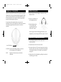
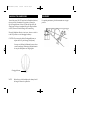
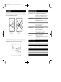
WHR100 Manual(1J1369)
6/10/99
W i re l e s s
Headphones
1:43 PM
Page 1
Infra
R E D
w ith I n fr a re d Tr a n s m i t t e r
In the
same
room,
invisibly
connect
with
v i rt u a l l y
a n y T V,
VCR or
S t e re o
System.
Line-of-sight
transmission
for freedom
from cables
WHR100
WHR100 Manual(1J1369)
6/10/99
1:43 PM
Page 2
INTRODUCTION
Thank you for purchasing RCA Wireless Headphones. This
wireless stereo infrared headphone system allows you to listen
to TV, VCR, Audio Components, or other audio sources at your
desired volume level without disturbing others in the room and
without being tied to the audio source by a wire.
SYSTEM COMPONENTS
INFRARED TRANSMITTER
Charging Contacts
Quick Charge
Indicator
The system consists of two components:
• Infrared Transmitter
• Headphone Receiver
The Transmitter connects to your audio source (TV, VCR, etc.)
and transmits the audio signal by infrared light to the
Headphone Receiver. The transmitter features - Auto Power On
Indicator, and Quick Charge Indicator on the front. The
Transmitter also serves as a recharging base for the
Headphones.
Auto Power
ON/Signal
Strength Indicator
3.5mm Audio In
RCAAudio IN
DC In
HEADPHONE RECEIVER
The Headphone Receiver captures infrared light and changes it
back into a sound signal. The headphones feature - built-in
Infrared detectors, on-off switch and volume control switch.
In addition to the usage at home with TV, VCR, Audio
Component and Radio, this headphone system is also perfect for
the usage in class room, hospitals, meetings, churches, as a hearing aid, and for the purpose of language translation.
Battery Door
Volume Controls
Battery Door
Power On/OFF
Switch
WHR100 Manual(1J1369)
6/10/99
1:43 PM
Page 4
INSTALLATION
INSTALLATION
1) Connect the DC Power Adapter to the DC IN Connector on
the back of the Transmitter.
RCA JACK TYPE HOOK-UP
To:
Audio Out (L &
R)
2) Plug the AC/DC Adapter into a standard wall outlet.
Typical
Connection For:
Receiver
CD Player
VCR
TV
AC/DC
Adapter
DC IN
3) Connect the Transmitter to the Audio Source component
using either the audio jack or the mini plug hook-up.
The Transmitter has AUDIO IN connectors for either Stereo
RCAtype plugs or Mini Plug Connectors (Commonly used
as Headphone connectors).
The “Y” Adapter, mini plug to RCAtype plug, which was
included is a universal type that can be used to connect most
audio sources to the transmitter. However, a standard audio
cable with RCAtype plugs on both ends and a mini-plug can
both be used with either of the input connections provided, if
desired.
See illustrations on right.
MINI PLUG HOOK-UP
To:
Audio Out or
Headphone
Connection
Typical
Connection For:
Portable CD Player
Audio Rack System
WHR100 Manual(1J1369)
6/10/99
1:43 PM
Page 6
OPERATION OF TRANSMITTER
The Green Auto ON/OFF indicator will be onwhen you plug the
adapter in the AC source and connect the audio plug to the audio
source. If the Auto On indicator is not lit (but the audio source is
ON) adjust the audio source output level which is greater than
the auto on indicator light in input level.
For protection of the transmitter and to save power, the
transmitter will be cut off automatically in the about one minute
when the input signal from audio source is too weak for
operation.
BATTERY INSTALLATION
1) Remove battery door by pushing in on the arrow at the
bottom of cover.
2) Insert one AAABattery for
each headphone earcup.
3) Replace the battery door
cover by sliding in the
opposite direction of the
arrow until it “snaps”.
When using the AAANi-Cd Rechargeable battery in your
headphones, you must charge for 24 Hours prior to first use.
OPERATION OF HEADPHONE RECEIVERS
1) Set the Headphone Receiver’s VOL control to the
minimum position.
Auto ON Indicator
CAUTION: Under normal working condition, the surface
of the transmitter will be slightly hot.
NOTE:
High levels from source may overload the
transmitter.
2) Turn the Receiver’s ON/OFF switch to ON.
3) Increase the Receiver’s VOL control setting slowly until you
hear the sound source which is connected to the transmitter.
Then, adjust the Receiver’s VOLcontrol for the desired listening level.
4) Adjust the size of the headphone by pulling down each end
(or pushing up to shorten).
WHR100 Manual(1J1369)
6/10/99
1:43 PM
Page 8
CHARGING THE HEADPHONES
Turn off the power ON/OFF switch on the Headphone Receiver,
then rest it on the Transmitter. If the position is correct, the
Quick Charge Indicator will turn ON (the red light will be lit).
After the quick charge is completed, the quick charge indicator
will OFF, however the trickle change will be continuing.
When the Headphone Receiver is not in use, be sure to switch it
to the OFF position to avoid damaging the battery.
CAUTION: Do not use other kind of Rechargeable battery to
replace the Ni-Cd quick charge (AAA) battery.
You may use Alkaline AAABatteries however, these
can not be recharged. When using Alkaline batteries
do not place Headphones on Charging Base.
Charging Indicator
NOTE:
Before first use of the headphone, the battery should
be charged 24 hours for optimal use.
PLACEMENT
For optimal performance, place the transmitter on an upper
position.
WHR100 Manual(1J1369)
6/10/99
1:43 PM
Page 10
PLACEMENT
TROUBLE SHOOTING
Avoid placing the transmitter facing the window as the infrared
ray will escape through the window.
OPTIMUM
POSITION
ON/OFF Indicator not Lit
• AC Adapter is not inserted into power outlet
• AC plug is not inserted in the transmitter
• The audio cord is not plugged in the audio source.
• No audio output from the audio source output.
No sound of receiver
• Transmitter is not ON
• Receiver has no battery in it
• Wrong direction of battery inserted in receiver.
Sound too low on receiver
• Input audio signal of transmitter is low.
• Receiver volume control is low.
• Battery needs recharging.
Poor sound quality
• Receiver volume control is high.
• Battery needs recharging.
• Distance is out of receiver range.
• Input level of transmitters is too high
(decrease the audio source volume.)
POOR
POSITION
• Distance is out of receiver range.
• Direction is inappropriate
(Relocate the transmitter and receiver to obtain the
best desired effect)
Interrupting Noise
Numbers of receivers can be used with on transmitter as long as
the infrared ray can reach the sensor of the receivers.
SPECIFICATIONS
Transmission Mode:
Infrared (800-900nM)
Sub Carrier Frequency
L - 2.3 MHz, R - 2.8 MHz
Operating Voltage
Transmitter, 12V DC (AC/DC Adapter)
Receiver, 2 x 1.2V (AAA) Ni-Cd Quick Charge Battery
Frequency Response
40 - 12 Khz
Signal Noise Ratio
49 dB
Distortion
3%
Channel Separation
38 dB
Operation Distance
7m
NOTE: All specifications are subject to change without notice.
WHR100 Manual(1J1369)
6/10/99
1:43 PM
Page 12
ONE YEAR LIMITED WARRANTY
Thomson Consumer Electronics, Inc. warrants that for one year
from the date of purchase this product is free from defects in
material and workmanship. If the item is defective within that
period, return it at your expense to the dealer from whom it was
purchased together with proof of purchase for replacement. The
exchange unit is under warranty for the remainder of the original
product’s warranty period. This warranty excludes defects or
damage due to misuse, abuse, neglect or acts of God, including
but not limited to lightning damage. The foregoing represents
Thomson’s sole obligation under this warranty.
This warranty gives you specific legal rights, and you may have
other rights which vary from state to state. For purchases
outside the United States, contact your dealer for warranty
information.
Thomson Consumer Electronics, Inc.
Product Exchange Center
32 Spur Drive
El Paso, Texas 79906
1J1369
Trademark(s) ® Registered
Marca(s) Registrada(s)
Made In China
©


![1] 設置位置の決定](http://vs1.manualzilla.com/store/data/006561423_3-e6f92f730a2adbc6917f237743ca73c7-150x150.png)