1
to radio communications. However, there is no
guarantee that interference will not occur in a
particular installation. If this equipment does
cause harmful interference to radio or television
reception, which can be determined by turning the
equipment off and on, the user is encouraged to
try to correct the interference by one or more of
the following measures:
- Reorient or relocate the receiving antenna.
- Increase the separation between the
equipment and receiver.
- Connect the equipment into an outlet on a
circuit different from that to which the receiver
is connected.
- Consult the dealer or an experienced radio/
TV technician for help.
• When you are not going to use the unit for a long
period of time, disconnect the AC power cord.
user Manual
Condensation Information
• When left in a heated room where it is warm and
damp, water droplets or condensation may form
inside the unit. When there is condensation inside
the unit, the unit may not function normally. Let the
unit stand for 1-2 hours before turning the power
on, or gradually heat the room and let the unit dry
before use.
RT151
Home Theater System
Rating Plate Location
The rating plate is located on the rear of unit.
FCC Statements
NOTE: This equipment has been tested and
found to comply with the limits for a Class B digital
device, pursuant to Part 15 of the FCC Rules.
These limits are designed to provide reasonable
protection against harmful interference in a
residential installation. This equipment generates,
uses and can radiate radio frequency energy
and, if not installed and used in accordance with
the instructions, may cause harmful interference
AVC Multimedia,
Markham, Ontario L3R 1E3
http: //www.RCAav.com
Read these instructions before using your new product for the first time.
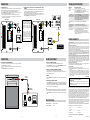
Safety Precautions
The lightning flash
with an arrowhead
within a triangle alerts you
to uninsulated dangerous
voltage within the product’s
enclosure that could cause an
electric shock.
IMPORTANT SAFETY
INSTRUCTIONS
The exclamation point
within a triangle alerts
you to the presence of important
operating, maintenance and
servicing instructions in this
user’s manual.
The symbol for Class II
(Double Insulation)
1) 2) 3) 4) 5) 6) 7) Read these instructions.
Keep these instructions.
Heed all warnings.
Follow all instructions.
Do not use this apparatus near water.
Clean only with dry cloth.
Do not block any ventilation openings.
Install in accordance with the
manufacturer’s instructions.
8) Do not install near any heat sources such
as radiators, heat registers, stoves, or
other apparatus (including amplifiers)
that produce heat.
9) Do not defect the safety purpose of
the polarized or grounding-type plug.
A polarized plug has two blades with
one wider than the other. A grounding
type plug has two blades and a third
grounding prong. The wide blade or
the third prong are provided for your
safety. If the provided plug does not fit
into your outlet, consult an electrician
for replacement of the obsolete outlet.
10) Protect the power cord from being
MAINS.
THE MAINS PLUG OF UNIT SHOULD NOT
BE OBSTRUCTED OR SHOULD BE EASILY
ACCESSED DURING INTENDED USE.
CAUTION:
BATTERY SHALL NOT BE EXPOSED TO
EXCESSIVE HEAT SUCH AS SUNSHINE, FIRE
OR THE LIKE.
Shouldanyproblemsoccur,disconnect
the AC power cord and refer servicing
to a qualified technician.
Do not place anything directly on top
of the unit, it may cause damage.
WARNING:
TO REDUCE THE RISK OF ELECTRIC SHOCK,
DO NOT REMOVE COVER (OR BACK). NO
USER-SERVICEABLE PARTS INSIDE. REFER
SERVICING TO QUALIFIED PERSONNEL.
TO PREVENT FIRE OR SHOCK HAZARD, DO NOT
EXPOSE THIS UNIT TO RAIN OR MOISTURE.
THE UNIT SHALL NOT BE EXPOSED TO
DRIPPING OR SPLASHING AND THAT NO
OBJECTS FILLED WITH LIQUIDS, SUCH AS
VASES, SHALL BE PLACED ON UNIT.
TO BE COMPLETEDLY DISCONNECT THE
POWER INPUT, THE MAINS PLUG OF UNIT
SHALL BE DISCONNECTED FROM THE
Placement Information
it somewhere with poor air flow, by covering
it with a cloth, or by placing it on bedding or
carpeting.
• Do not use this unit in places which are extremely
hot, cold, dusty, or humid.
• In a cabinet, allow about 2.5cm (1 inch) of free
space around the unit for adequate ventilation.
• Place the unit on a flat and even surface.
• Do not restrict the air flow of this unit by placing
WARNING:
CHANGES OR MODIFICATIONS TO THIS
UNIT NOT EXPRESSLY APPROVED BY THE
PARTY RESPONSIBLE FOR COMPLIANCE COULD
VOID THE USER AUTHORITY TO OPERATE THE
EQUIPMENT.
Safety Information
• When connecting or disconnecting the AC power
cord, grip the plug and not the cord itself. Pulling
the cord may damage it and create a hazard.
11)
12)
13)
14)
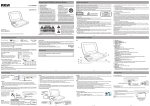
GETTING STARTED
TO CHANGE THE REMOTE
CONTROL BATTERY
1. Open the battery door.
2. Insert one CR2025 (3V) size
battery.
• Point the remote control at the REMOTE SENSOR located
on the unit.
• When using this unit in very bright light, the infrared REMOTE
CONTROL SENSOR may not work properly.
• The recommended maximum distance for using the remote
control is about 16 feet (5 meters).
123 4
5
6
1.
2.
3.
4.
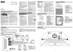
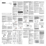
Remote Control Sensor
STANDBY indicator
Green Light : the unit is in turned ON.
Amber Light : the unit is in STANDBY.
ON/STANDBY button
SOURCE button
Switches the sound input source
(between DVD IN, LINE IN or AUX IN).
Press repeatedly to select different
sources.
5. VOLUME +/- buttons
Adjusts the volume and the level of all
speakers.
6. LINE IN jack
Connects to the Audio Out of portable
audio players or other audio devices
7. SUBWOOFER
BATTERY REPLACEMENT
When the battery becomes weak, the operating distance of
the remote control will be greatly reduced and you will need
to replace the battery.
Note: If the remote control is not going to be used for a long
time, remove the battery.
WARNING:
Do not dispose of
the battery in a fire or it may
leave and/or explode.
CAUTION:
Danger of explosion if battery
is incorrectly replaced.
Replace only with the same or
equivalent type.
7
REFERENCE GUIDE
walked on or pinched particularly at plugs,
convenience receptacles, and the point
where they exit from the apparatus.
Only use detachments/accessories
specified by the manufacturer.
Use only with the cart, stand, tripod,
bracket, or table specified by the
manufacturer, or sold with the apparatus.
When a cart is used, use
caution when moving the
cart/apparatus combination
to avoid injury from tip-over.
Unplug this apparatus during lightning
storms or when unused for long periods
of time.
Refer all servicing to qualified service
personnel, Servicing is required when
the apparatus has been damaged in any
way, such as power-supply cord or plug
is damaged, liquid has been spilled or
objects have fallen into the apparatus,
the apparatus has been exposed to rain
or moisture, does not operate normally,
or has been dropped.
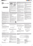
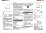
REMOTE CONTROL
1
6
2
3
7
8
4
5
9
10
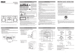
UNIT - Rear
4. CHANNELS button
Switches between 5.1 (SURROUND
SOUND) and 2.1 (STEREO with
SUBWOOFER) sound modes.
5. MUTE button
Instantly turns off the sound. Press
again to restore the sound.
6. FRONT -/+ buttons
Decreases / increases the level of
FRONT L/R speakers.
7. CENTER -/+ buttons
Decreases / increases the level of
CENTER speaker.
8. REAR -/+ buttons
Decreases / increases the level of
REAR L/R speakers.
9. SUBWOOFER -/+ buttons
Decreases / increases the level of
SUBWOOFER.
10.MASTER VOLUME -/+ buttons
Adjusts the volume and the level of all
speakers.
1. ON/STANDBY button
2. SOURCE button
Switches the sound input source (between
DVD IN, LINE IN or AUX IN) press
repeatedly to select different sources.
3. RESET button
Adjusts all speakers to their original
factory default settings.
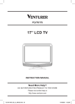
CONNECTIONS
1.POWER CONNECTION
3.SPEAKERS POSITIONING
8. DVD IN jack
Connects to the Audio Out of DVD
player, VCR, etc.
9. AUX IN jack
Connects to the Audio Out of TV or
other audio devices.
10.FRONT Left Speaker terminal
11.FRONT Right Speaker terminal
12.CENTER Speaker terminal
13.SURROUND Left Speaker terminal
14.S U R R O U N D R i g h t S p e a k e r
terminal
15.POWER CORD
8
9
10
11
12
13
14
15
E-3
CONNECTIONS
Note :
•Before you plug in the unit, make sure that the rated voltage of your unit matches your
local voltage.
•Keep your hands dry when you are connecting the power cord to the wall outlet to avoid
electric shock.
•When you are not going to use the unit for a long period of time, disconnect the power cord.
UNIT - Front
Using the Remote Control
Remove the
PLASTIC sheet
before using
the remote
control.
E-2
E-1
REFERENCE GUIDE
E-4
•When the player is in the standby mode, it is still consuming some power. If you wish
to disconnect the unit completely from the power, unplug the power cord from the AC
outlet.
•TO PREVENT ELECTRIC SHOCK, MATCH WIDE BLADE OF PLUG TO WIDE SLOT,
FULLY INSERT.
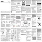
2.CONNECTING THE SPEAKERS & SUBWOOFER
FRONT
(LEFT)
IMPORTANT :
Switch off the power before connecting equipment.
The speakers cords have been color-coded to simplify
connection. Just plug the speaker wire into the corresponding
jacks on the rear of the unit, matching the color tube on the end
of the speaker wire to the color-coded connector.
FRONT (LEFT)
CENTER
FRONT
(RIGHT)
FRONT (RIGHT)
REAR OF UNIT
SUBWOOFER
R
L
DVD
IN
AUX
IN
Black &
White
CENTER
Black &
Red
SURROUND
(RIGHT)
SURROUND
(LEFT)
SPEAKERS 4
FL
FL
FR
FR
CT
CT
SL
SL
SR
SR
Black &
Green
Black &
Grey
HAUT-PARLEUR 4
To wall
outlet
SURROUND
(RIGHT)
E-5
Black &
Blue
LISTENING
POSITION
CAUTION :
•To prevent damage the unit, be
sure to turn off the unit before
making any connection.
•Connecting speakers other
than the speakers supplied
with the unit may damage the
unit.
SURROUND
(LEFT)
E-6
Trouble Shooting Guide
CONNECTIONS
4.CONNECTING TO TV
5.CONNECTING TO DVD PLAYER / VCR / GAME CONSOLE / VIDEO
CAMERA
• Connect the audio cable to the white jack of AUX IN (L) and red jack of AUX IN (R) on the
rear of unit, and then connect to the corresponding AUDIO OUT jacks on your TV.
• Turn on your TV. This will allow your TV’s sound to play through the unit.
• Press the SOURCE button to select AUX IN mode. You should now hear your TV’s
audio over your Home Theater’s speakers. If you don’t:
1. Please check the volume settings on both your Home Theater and your TV.
2. For some TV’s (this is quite rare) you may need to ensure your TV’s Audio Output
is enabled (see TV’s setup menu).
REAR OF UNIT
R
(red)
L
DVD
IN
AUX
IN
NOTE : In order to have TV sound
come through this Home Theater
System, your TV must have AUDIO
OUT jacks. These jacks will typically
be located on the rear or side of
the TV (not in the front). Most, but
not all TV’s have these Audio Out
jacks.
Audio Cable
(supplied)
(white)
SPEAKERS 4
FL
FL
FR
FR
CT
CT
SL
SL
SR
SR
(red)
• Connect the audio cable to the white jack of DVD IN (L) and red jack of DVD IN (R)
on the rear of unit, and then connect to the corresponding AUDIO OUT jacks on your
DVD PLAYER / VCR / Game Console / Video Camera.
• Turn on DVD PLAYER, VCR, Game Console or Video Camera. This will allow your DVD
PLAYER / VCR / Game Console / Video Camera’s sound to play through the unit.
• Press the SOURCE button to select DVD IN mode.
(white)
To AUDIO OUT
HAUT-PARLEUR 4
REAR OF UNIT
GAME
To AUDIO OUT
L
DVD
IN
(white)
AUX
IN
(white)
To VIDEO OUT
SPEAKERS 4
NOTE: If you use a Cable or
Satellite Box to view TV content,
you should be able to use the Audio
Out connection on the Cable or
Satellite Box to listen to TV audio
through your Home Theater. Simply
connect to the Home Theater’s
AUX IN.
FL
FL
FR
FR
CT
CT
SL
SL
SR
Only supplied 1
set of Audio cable
To wall outlet
To wall outlet
E-8
CONNECTIONS
SOUND ADJUSTMENT
6.CONNECTING TO OTHER EQUIPMENT
TO ADJUST THE MASTER VOLUME
• Connect an audio cable to the LINE IN jack on the front of unit and the jack of AUDIO
OUT/HEADPHONE of your equipment.
• Turn on your other equipment. This will allow your equipment’s sound to play through
the unit.
• Press the SOURCE button to select LINE IN mode.
• Point the remote control at the REMOTE SENSOR located on the unit.
• Press the VOLUME +/- buttons on the unit or the VOLUME MASTER +/- button on
the remote control to adjust the level of all speakers.
TO ADJUST THE VOLUME OF INDIVIDUAL SPEAKER
• Point the remote control at the REMOTE SENSOR located on the unit.
• Directly press the + or - button on the remote control to increase or decrease the level
of the corresponding speaker(s).
TO RESET
Audio Cable
(not supplied)
• Press the RESET button on the remote control to return to factory default speaker
settings.
TO CHANGE THE SPEAKER CHANNEL
• Press the CHANNELS button on the remote control to select the listening mode. This
will switch between 5.1 (SURROUND MODE) and 2.1 (STEREO with SUBWOOFER).
We recommend you leave system in 5.1 mode. The Center and Rear Surround speakers
will not be active if system is in STEREO mode.
To AUDIO OUT or
HEADPHONE jack
• Check that the AC power cord is connected.
No sound.
• Press the VOLUME + button to increase volume.
• Ensure the MUTE button is not pressed on the remote control.
• Ensure the SOURCE selection is correct.
No sound from one
channel or unbalanced
left and right volume.
Try pressing the RESET button on remote control. If this doesn’t
help, try pressing the CHANNEL button on remote control (this will
switch system between 5.1 SURROUND and STEREO modes).
• Check the speaker connections of the inoperative channel.
• Check the speaker cord connection and speaker location.
• Adjust individual speaker volumes.
Reversed left and right
sound.
• Check the speaker connection for proper phasing.
The center speaker or
the surround speakers
give no sound.
• Check the speaker connections are correct.
• The current mode does not support surround sound.
The remote control
does not function.
• Remove any obstacles between the remote control and the unit.
• Use the remote control near the unit.
• Point the remote control at the remote sensor on the unit.
• Replace the battery in the remote control with new one.
• If there is a clear plastic strip sticking out from the rear of the
remote control, pull it out.
LIMITED WARRANTY
SR
HAUT-PARLEUR 4
To VIDEO IN
E-7
CAUSE AND SOLUTION
No power.
(red)
(red)
R
SYMPTOM
Note:
• Surround speakers and center speaker volume adjustments can only be made from
the remote control in 5.1 channel speaker mode, not in 2.1 channel speaker mode.
• Press the MUTE button to turns off the sound instantly. Press again to restore the
sound.
SPECIFICATIONS
Power requirement
Power Consumption
: AC ~ 120V 60Hz
: 35W
AVC MULTIMEDIA ("AVC") makes the following limited warranty. These limited warranties
extend to the original consumer purchaser and is limited to non-commercial user of the
product.
One Year Parts & Labor Warranty
AVC products purchased in the United States are warranted to be free from defects in
materials or workmanship for a period of one year from the date of their original retail
purchase. If the unit fails to conform to this warranty, we will service the product using new or
refurbished parts and products, at AVC's sole discretion.
During a period of one year from the effective warranty date, AVC will provide, when needed,
service labor to repair a manufacturing defect at its designated Service Center. To obtain
warranty service in the United States, you must first call our Customer Support Center at
1-877-252-6873, during the hours listed in the box below. The deternination of service will
be made by AVC customer support.
PLEASE DO NOT RETURN YOUR UNIT TO AVC WITHOUT PRIOR AUTHORIZATION.
New or remanufactured replacements for defective parts or products will be used for repairs
by AVC at its designated Service Center for one year from the defective warranty date. Such
replacement parts or products are warranted for an additional one year from the date of repair
or replacement. The Customer will be required to ship the unit to the Service Center indicated
at the time Customer Support is contacted to make the necessary repairs. The customer is
responsible for all transportation charges to the service facility.
Packaging and Shipping Instruction
When you send the product to the AVC service facility you must use the original carton box
and packing material or an equivalent as designated by AVC.
Your Responsibility
(1) You must retain your bill of sale to provide proof of purchase.
(2) These warranties are effective only if the product is purchased and operated in the U.S.A.
or Canada.
(3) Warranties extend only to defects in material or workmanship, and do not extend to any
product or parts which have been lost or discarded, or damage to product or parts caused
by misuse, accident, improper operation or maintenance, or use in violation of instructions
provided with the product, or to product which has been altered or modified without
authorization of AVC, or to products or parts thereof which have had the serial number
removed or changed.
Out of Warranty
In the event your product requires repair after the limited warranty period has expired, please
contact our Customer Support Center at 1-877-252-6873 or
www.rcaav.com
Hours: Monday-Thursday: 9am-7pm, Friday: 9am-5pm, Saturday: 9am-NOON Eastern time.
Important:
You are responsible for any transportation, shipping or insurance relative to the return of the
product to our Product Returns Center.
All warranties implied by state law, including the implied warranties of merchantability and
fitness for a particular purpose, are expressly limited to the duration of the limited warranties
set forth above. With the exception of any warranties implied by state law as hereby limited,
the foregoing warranty is exclusive and in lieu of all other warranties, guarantees, agreements
and similar obligations of manufacturer or seller with respect to the repair or replacement of
any parts. In no event shall AVC be liable for consequential or incidental damages.
No person, agent, distributor, dealer or company is authorized to change, modify or extend
the terms of these warranties in any manner whatsoever. The time within action must be
commenced to enforce any obligation of AVC arising under the warranty or under any statute,
or law of the United States or any state thereof, is hereby limited to one year from the date of
purchase. This limitation does not apply to implied warranties arising under state law.
This warranty gives you specific legal rights and you may also have other rights, which
may vary from state to state. Some states do not allow limitation on how long an implied
warranty lasts, when an action may be brought, or the exclusion or limitation of incidental or
consequential damages, so the above provisions may not apply to you.
For more information on other products and services, please contact our web site at www.rcaav.com
Important: Also keep your “Bill of Sale” as proof of purchase.
Model no. ............................................ Product name .........................................................
Type of set ............................................................................................................................
Serial no. .............................................Invoice no. ..............................................................
Date purchased ...................................Dealer name ...........................................................
FOR SERVICE AND REPAIR, PLEASE VISIT www.
E-9
E - 10
Printed in China
rcaav.com
811-R15191W010