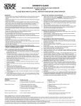
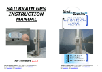
1
Distributed by
Any reference to Raytheon or
RTN in this manual should be
interpreted as Raymarine.
The names Raytheon and RTN
are owned by the
Raytheon Company.
Chapter 2: Installation
1
ST80
Autopilot
Keypad
Operation Manual
resp
disp
trac
k
-1
+1
-10
+10
stan
dby
auto
aut
opi
lot
ST80 Autopilot Keypad Operation Manual
Package Contents
1. Autopilot keypad
2. Thumb nuts (2)
3. Threaded fixing studs (2)
4. White sun cover
5. SeaTalk cable
6. Installation template
7. Operation manual
8. Warranty card
9. Operation cue card
10. Keypad installation guide
1
2
ST80 Autopilot Keypad Operation Manual
Contents
Chapter 1: Introduction .............................................................. 3
1.1 Introduction .................................................................. 3
Chapter 2: Operation ................................................................. 4
2.1 Keypad Layout and Features ......................................... 4
2.2 Basic Operating Principles and Hints .............................. 5
Auto and Standby ........................................................ 5
Course Changes ........................................................... 5
Track .......................................................................... 5
Track Advance/Acceptance .................................. 6
Response ..................................................................... 6
2.3 Additional Autopilot Features for Sailing Vessels ........... 7
Autotack ..................................................................... 7
Wind Trim .................................................................. 7
Using Wind Trim ......................................................... 7
2.4 Keypad Illumination ..................................................... 8
2.5 LED Status ................................................................... 8
2.6 Important Safety Information ........................................ 9
2.7 Alarms ......................................................................... 9
Chapter 3: EMC and Servicing Guidelines ............................... 10
3.1 Important information ................................................. 10
3.2Installation .................................................................. 10
3.3 Check Before Going to Sea .......................................... 11
3.4 Servicing and Safety ................................................... 11
Chapter 4: Specification .......................................................... 12
3
ST80 Autopilot Keypad Operation Manual
Chapter 1: Introduction
1.1 Introduction
The Autopilot keypad provides autopilot control via a simple ninekey interface. There are buttons for engaging and disengaging the
pilot (auto and standby), course adjustment (-1, +1, -10 and +10),
track control, response and direct entry to the autopilot display’s of a
Masterview display head (disp).
resp
disp
trac
k
-1
+1
-10
+10
stan
dby
auto
aut
opi
lot
D1940-1
4
ST80 Autopilot Keypad Operation Manual
Chapter 2: Operation
2.1 Keypad Layout and Features
The autopilot keypad has been designed as a control interface for
Autohelm autopilot’s. The keypad consists of nine push-button keys
together with operation status LED’s. The basic function of each of
these keys is described in the following illustration.
resp
disp
trac
k
-1
+1
-10
+10
stan
dby
auto
aut
opi
lot
ST80 Autopilot Keypad Operation Manual
5
• When the system is switched on the autopilot is always in
STANDBY mode.
• The display and lamp key only cycles pilot pages when the pilot
chapter is open.
2.2 Basic Operating Principles and Hints
Auto and Standby
Autopilot operation has been simplified to a set of push-button keys,
all of which are confirmed by a beep or beeps.
Engaging the autopilot could not be easier. Simply steer your vessel
onto the required heading, press the AUTO button and release the
wheel/ tiller. When you want to return to manual steering simply
press STANDBY and regain control.
Caution:
Hand steering is not possible when your vessel is under
autopilot control. The pilot MUST be disengaged by pressing
STANDBY. It is the skippers responsibility to ensure that all crew
members are aware of this procedure.
Course Changes
Course changes under autopilot control are made using the –1, +1,
–10 and +10 keys. These keys allow you to make changes in 1° or
10° increments to port (–) and starboard (+).
Track
Track mode tells the autopilot to steer under the supervision of a
radio or satellite navigation system. Therefore, the following basic
guidelines should be observed before track is engaged:
• Always steer your vessel to within 0.1nm of the track.
• Make sure that there are no navigational hazards either side of the
intended track.
• Maintain an accurate log.
• Make regular plots to verify the computed position provided by your
position transducer.
• Maintain a proper lookout at all times.
6
ST80 Autopilot Keypad Operation Manual
Track Advance/Acceptance
If your navigation receiver is transmitting waypoint number and
bearing to waypoint, a waypoint alarm will sound whenever a new
target waypoint is selected. The autopilot maintains the current
heading and automatic track control is suspended. Check the new
bearing to waypoint, make sure that it is safe to turn, and then return
to automatic track control by simply pressing the track key. The new
target waypoint is accepted and the autopilot steers your vessel onto
the new heading.
You may find that the tidal offset is very different on the new bearing.
Therefore, it is advisable to check the cross track error (XTE) after a
couple of minutes. If the cross track error increases, make a course
adjustment (e.g., 10°) in the direction of the arrow. This helps to
speed up track control correction for the new tidal vector.
Response
There are three response levels.
Level 1 is the default and suitable for most situations. This setting
provides the best compromise between course-keeping accuracy and
power consumption.
Level 2 ensures tighter course-keeping at the expense of increased
power consumption and wear and tear due to increased pilot activity.
It is advisable to use the minimum response necessary to achieve the
desired course keeping accuracy.
On larger vessels, level 3 can improve slow speed steering where
natural yaw damping of the vessel is reduced.
Note: Level 3 is not recommended for use at planing speeds, or in rough
seas if a rate gyro transducer is not fitted.
7
ST80 Autopilot Keypad Operation Manual
2.3 Additional Autopilot Features for Sailing
Vessels
Autotack
When the autopilot is in compass or windvane mode, the following
key command selects autotack mode.
-1
resp
disp
track
Press these keys together momentarily to
begin a tack turning to port.
-10
-1
+1
-10
+10
+1
standby
auto
+10
Press these keys together momentarily to
begin a tack turning to starboard.
autopilot
D2428-1
This mode starts a tack routine so that you can tend to the sheets.
Note: Your vessels rudder reference transducer must be accurately
aligned as the autotack feature mirrors standing helm. Any
offset will change the initial tack angle.
Wind Trim
This feature ensures that the autopilot ignores short term changes in
wind direction, yet tracks real windshifts.
standby
resp
disp
track
Press these keys together momentarily to
select Wind Trim and maintain the current
apparent wind angle.
auto
-1
+1
-10
+10
standby
auto
Press and hold these keys for 1 second
to return to the previous apparent wind
angle.
autopilot
D2429-1
Using Wind Trim
It is important to remember that Wind Trim prevents overreaction to
gusts or sudden wind shifts, and that it takes at least 1 minute to
change the heading in response to a permanent change to the
apparent wind angle.
8
ST80 Autopilot Keypad Operation Manual
In gusty conditions, always sail a few degrees off of the wind and pay
frequent attention to sail trim and helm balance, using the rudder
angle display on a Masterview display head.
Generally speaking, performance will be improved by reefing the
headsail and mainsail a little early rather than too late.
2.4 Keypad Illumination
The keypad illumination can be adjusted as follows:
Press for 1 second to enter illumination
adjustment mode.
disp
resp
disp
track
-1
+1
-10
+10
standby
auto
If the illumination is OFF, the illumination
will now be set to level 3.
When illumination adjustment is active,
press this key momentarily to cycle the
available levels: 1, 2, 3, OFF.
autopilot
D2432-1
The keypad returns to normal operation after 8 seconds of keypad
inactivity.
2.5 LED Status
The actions described in this chapter are confirmed on the display of
a Masterview display head. However, if the Autopilot keypad is
installed away from a display head, the functions can be identified by
the permanent illumination or flashing LED’s as shown in the
following illustration.
Flashes when
adjusting response.
LED glows when track
engaged.
resp
Flashes if waypoint
advance to port.
Flashes during
rudder gain
adjustment.
disp
track
-1
+1
-10
+10
standby
auto
autopilot
Flashes if waypoint advance
to starboard.
Autopilot status LED glows
permanently in AUTO and
MANUAL modes. Flashes in
VANE and STANDBY modes.
D2433-1
9
ST80 Autopilot Keypad Operation Manual
2.6 Important Safety Information
The following rules should ALWAYS be observed when passage
making under autopilot control:
Maintain a permanent watch and regularly check all around for
other vessels and obstacles – no matter how clear the sea may
appear to be, dangerous situations can develop in minutes.
Maintain an accurate log of your vessels position by visual
bearings or radio/satellite position fixes.
Maintain a continuous plot of your position on a current chart.
Make sure that the autopilot heading will steer you clear of
obstacles. Always allow for tidal set – the autopilot cannot!
Even when your autopilot is locked onto a given track using a
radio/satellite navigation receiver, always maintain a log and
regular position plot – navigational signals can produce
significant errors in certain circumstances, errors which the
autopilot cannot detect.
Ensure that your crew is familiar with the procedures for
engaging and disengaging the autopilot.
When there is restricted sea room, make sure that a crew
member is stationed close to the autopilot keypad.
On power vessels, always maintain a permanent watch at the
steering station when the autopilot is engaged.
2.7 Alarms
The keypad sounds audible alarms in response to the following alarm
conditions:
Alarm
Response
Waypoint advance
Two beeps for port one for starboard
Low battery
Continuous beep, beep
Large XTE
Continuous beep, beep
Wind change
Continuous beep, beep
No NMEA data
Continuous beep, beep
NMEA data error
Continuous beep, beep
Watch
Continuous beep, beep
Off course
Continuous beep, beep
Note: These alarms are normally displayed on a Masterview display head.
Please refer to the Masterview handbook for details.
10
ST80 Autopilot Keypad Operation Manual
Chapter 3: EMC and Servicing Guidelines
3.1 Important information
All Autohelm equipment and accessories are designed to the best
industry standards for use in the leisure marine environment.
Their design and manufacture conforms to the appropriate
Electromagnetic Compatibility (EMC) standards, but good
installation is required to ensure that performance is not
compromised. Although every effort has been taken to ensure that
they will perform under all conditions, it is important to understand
what factors could affect the operation of the product.
3.2 Installation
To avoid the risk of operating problems, all Autohelm equipment and
cables connected to it should be:
• At least 1m (3 feet) from any equipment transmitting or cables
carrying radio signals, e.g., VHF radios, cables and antennas. In the
case of SSB radios, the distance should be increased to 2m (7ft).
• More than 2m (6ft) from the path of a radar beam. A radar beam can
normally be assumed to spread 20 degrees above and below the
radiating element.
• The equipment should be supplied from a different battery than the
one used for engine start. Voltage drops below 10V in the power
supply to our products can cause the equipment to reset. This will not
damage the equipment, but will cause the loss of some information
and can change the operating mode.
• Genuine Autohelm cables should be used at all times. Cutting and
rejoining these cables can compromise EMC performance and so
should be avoided unless doing so is detailed in the installation
manual.
• If a suppression ferrite is attached to a cable, this ferrite should not be
removed. If the ferrite has to be removed during installation it must
be reassembled in the same position.
ST80 Autopilot Keypad Operation Manual
11
3.3 Check Before Going to Sea
• Always check the installation before going to sea to make sure that it
is not affected by radio transmissions, engine starting etc..
• In some installations, it may not be possible to prevent the equipment
from being affected by external influences. In general this will not
damage the equipment but can lead to it resetting, or momentarily
may result in faulty operation.
3.4 Servicing and Safety
• Autohelm equipment should be serviced only by authorised
Autohelm service engineers. They will ensure that service
procedures and replacement parts used will not affect performance.
There are no user serviceable parts in any Autohelm product.
• Some products generate high voltages, and so never handle the
cables/connectors when power is being supplied to the equipment.
• Always report any EMC related problem to your nearest Autohelm
dealer. We will use any such information to improve our quality
standards.
12
ST80 Autopilot Keypad Operation Manual
Chapter 4: Specification
Dimensions:
110 x 68 x 17mm (4.33 x 2.67 x
0.66in)
Power supply:
10 to 16V DC
Current consumption:
Less than 240mA with
illumination fully on, and less than
90mA at the courtesy level.
Operating temperature:
-10 to 70°C (14 to 158°F)
Buzzer:
Single tone beep
Illumination:
3 levels
Audible alarms:
Drive stopped
Off course
Waypoint advance
Low battery
Large cross track error (XTE)
Wind change
No NMEA data
NMEA data error
Watch
81072-1
4
Raymarine Ltd.
Anchorage Park, Portsmouth,
P03 5TD, England.
Telephone: (44) (0) 2392 693611
Fax: (44) (0) 2392 694642
ST80 Navigator Keypad Installation and Operation Handbook