1
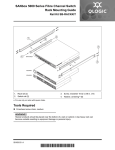
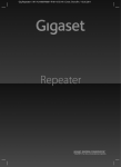
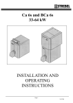
QUICK START GUIDE
[ Quick Start Guide ]
STACKABLE CHASSIS SWITCH INSTALLATION
QLogic 9000 Series
z
Purchasers of OEM products should consult with their OEM for support.
Please feel free to contact your QLogic approved reseller or QLogic Technical Support at
any phase of integration for assistance. QLogic Technical Support can be reached by the
following methods:
Web
http://support.qlogic.com
E-mail
[email protected]
The QLogic knowledge data base contains troubleshooting information for the QLogic
adapters. Access the data base from the QLogic Support Web page,
http://support.qlogic.com. Use the Support Center search engine to look for specific
troubleshooting information.
Quick Start Guide
Installation Instructions
Congratulations on your purchase of the QLogic® 9000 Series Stackable Chassis Switch. This guide describes the steps
to install and activate your new switch using a Windows® workstation. For advanced options and instructions (including
Solaris®, Linux®, and Mac OS X® installations), refer to the QLogic 9000 Series Stackable Chassis Switch Installation
Guide at www.qlogic.com.
NOTE:
Do not apply power to the switch until instructed in Step 5.
Step 1. Verify the Package Contents
The QLogic 9000 Series Stackable Chassis Switch is shipped with the following items:
1
2
1
1
1
NOTE:
QLogic 9000 Series Stackable Chassis Switch
AC Power cords
Rail kit
RJ-45/RS-232 console adapter
Enterprise Fabric Suite™ 2007 CD
I/O blades, transceivers, and stacking cables, if you ordered them, are packaged separately.
Step 2. Mount the Switch
WARNING!! Two people are required to safely lift and install the switch into a rack. To avoid personal injury or damage
to the switch, arrange for assistance.
You can mount the QLogic 9000 Series switch on a flat surface or in a rack. Allow minimum clearances of 2 inches in
front and 8 inches in the rear for cabling.
❑
For a rack mount, install the QLogic 9000 Series rail kit in a standard 19" rack as described in the QLogic 9000
Series Stackable Chassis Switch Rack Mounting Guide that is packaged with the switch.
Step 3. Install I/O Blades
❑
Remove I/O panels as needed to match the number of I/O blades to be installed. Pull the I/O panel by the latch to
disengage and remove. Every I/O slot must have an I/O blade or an I/O panel to ensure proper cooling.
❑
Install I/O blades. Open the I/O blade latch and slide the I/O blade into the chassis until it makes contact with the
midplane connector. Rotate the latch upward to lock the I/O blade in place.
3
Step 4. Install Transceivers
An SFP transceiver is required for each switch port that will be connected to a device.
❑
To install an SFP transceiver, insert the transceiver into the switch port and gently press until it snaps in place. The
transceiver will fit only one way. If the transceiver does not install under gentle pressure, flip it over and try again.
Step 5. Apply Power to the Switch
The maximum current requirements are 10 amps at 100 VAC or 4.2 amps at 240 VAC.
❑
Attach the AC power cords to the Power Supply blades
and wall outlets or power strips. Secure the strain
relief bales to the plugs. Place the On/Off switches in
the On position.
❑
The switch runs its self tests and begins normal
operation – this may take a few minutes. Observe the
Maintenance Panel and verify that the CPU0 blade
Heartbeat LED is blinking about once per second and
the Chassis Fault LED is NOT illuminated.
CHASSIS
GOOD LED
CHASSIS
FAULT LED
CPU0
HEARTBEAT
LED
Step 6. Verify Workstation Requirements
❑
❑
4
Verify that your workstation can support the Enterprise Fabric Suite 2007™ application with the following minimum
requirements:
■
Windows 2003, or XP SP1/SP2
■
512 MB memory minimum; 1GB recommended
■
150 MB disk space
■
1 GHz processor
■
Video card with 256 colors
■
CD ROM drive, RJ-45 Ethernet port
■
Internet Browser: Microsoft® Internet Explorer® 6.0, Netscape Navigator® 6.0, or Firefox® 1.5
■
Java® 2 Standard Edition Runtime Environment 1.4.2
The default IP address of a new switch is 10.0.0.1. Ensure that your workstation is configured to communicate
with the 10.0.0 subnet–for example, a workstation IP address of 10.0.0.10 with a subnet mask of 255.0.0.
Step 7. Connect the Workstation to the Switch
❑
Connect the CPU0 blade Ethernet port directly to the workstation using an Ethernet cable, or indirectly through a
switch or hub. The Ethernet port automatically discovers straight and cross-over cables. You must have a live
Ethernet connection when the workstation powers up.
NOTE:
The Maintenance Panel Ethernet ports on the front of the switch are disabled and should not be used for the
initial installation. You can enable the Maintenance Panel Ethernet ports after the switch is operational.
CPU0 BLADE
ETHERNET PORT
Step 8. Install Enterprise Fabric Suite 2007
The Enterprise Fabric Suite 2007 application includes the Configuration Wizard. This wizard auto-detects and configures
the switch based on selected options and recommended settings. To download and install the
Enterprise Fabric Suite 2007 application on a Windows workstation/server, perform the following steps:t
1.
Insert the Enterprise Fabric Suite 2007 disk into the CDROM drive.
2.
In the upper left corner of the product introduct screen, click Management Software.
3.
Click Install for Windows 2003, XP.
4.
Enter the serial number and license key provided to activate the Enterprise Fabric Suite 2007
application.
Step 9. Obtain Network Configuration
❑
Obtain the IP address and subnet mask from your network administrator. Be sure that your workstation is configured
for the same subnet.
5
Step 10. Run the Configuration Wizard
❑
Double-click the Enterprise Fabric Suite 2007 shortcut, or select Enterprise Fabric Suite 2007 from Start menu,
depending on how you installed it.
❑
The Configuration Wizard tool auto-detects and configures the switch based on selected options and recommended
settings. Follow the instructions to set network parameters and the password. The default user name is admin; the
default password is password.
NOTE:
If you are using an Ethernet switch and the auto-connect process fails due to a time out, try a direct Ethernet
connection from your workstation to the switch. Use an Ethernet cross-over cable only if your workstation has a GbE port.
Step 11. Connect Devices and Switches
❑
Connect fiber optic cables between the installed transceivers and their corresponding devices. Each port
auto-negotiates the proper port type with the connected device or switch.
Congratulations
You have successfully installed your QLogic 9000 Series Switch
For information about ordering additional I/O blades and accessories visit
http://www.qlogic.com/Products/SAN_products_FCS_san9000.aspx.
6
© 2009 QLogic Corporation. QLogic, the QLogic logo, and Enterprise Fabric Suite are trademarks or registered
trademarks of QLogic Corporation. Solaris and Java are registered trademark of Sun Microsystems. Linux is a registered
trademark of Linus Torvalds. Mac OS is a registered trademark of Apple Inc. Windows and Internet Explorer are registered
trademarks of Microsoft Corporation. NetScape Navigator is a registered trademark of NetScape Communications
Corporation. Firefox is a registered trademark of the Mozilla Foundation. All other brands and product names are
trademarks or registered trademarks of their respective owners. Information supplied by QLogic is believed to be accurate
and reliable. QLogic Corporation assumes no responsibility for any errors in this brochure. QLogic Corporation reserves
the right, without notice, to makes changes in product design or specifications.
Corporate Headquarters
QLogic Corporation
26650 Aliso Viejo Parkway
Aliso Viejo, CA 92656
949.389.6000 www.qlogic.com
*50688-05
50688-05 A
Europe Headquarters
QLogic (UK) LTD.
Quatro House, Lyon Way, Frimley
Camberley Surrey, GU16 7ER UK
+44 (0) 1276 804 670
A*