1
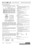
Ca 6s and BCa 6s
33-64 kW
INSTALLATION AND
OPERATING
INSTRUCTIONS
Page 1
31/07/00
CONTENTS:
PAGE:
General specification
3
Dimensions for Ca6s and BCa6s boilers.
4
Boiler room clearance requirements
5
Boiler block assembly
6
Boiler connections and jacket assembly
7
Diagram
8
BCa6s assembly
9
BCa6s electrical connections and jacket assembly
10
Diagram
11
Instrument control panel description
12
Continued
13
Control module options
14
Control module diagrams
15
Installation of electronic control modules
16
Terminal wiring diagram
17
Schematic wiring diagram
18
Important notes & burner connection information.
19
Page 2
31/07/00
ASSEMBLY INSTRUCTIONS FOR:
Ca 6s / BCa 6s
General Specifications
The STREBEL Camino 6s is a special boiler for oil or
gas fired pressure jet burner.
In the BICALOR construction a calorifier for the
supply of hot water is built onto the boiler.
CSH-S type calorifier are manufactured from 1.4571
high tensile steel with an incorporated heating coil of
galvanised copper ribbed pipe.
Triple pass block of cast iron sections.
The first pass is the combustion chamber. From there
the flue gases pass between the rear section and the last
intermediate section through the second pass to the
front of the boiler. They are then diverted into the third
pass and flow back to the rear through the flue spigot
into the chimney.
Calorifier:
Maximum operating pressure 10 bar
Maximum test pressure 13 bar
The boiler can be delived in individual sections
or as a boiler block. The accessories are packed
seperately. There are different orders of
assembly depending on the condition of supply.
when assembling and connecting the boiler, all
relevant instructions should be observed.
The boiler is to be erected on a base, or a level
floor which is capable of supporting the weight
of the boiler, water content and any ancillary
equipment. Refer to base details opposite.
Assembly, connections and the initial set-up
operation should be carried out by a qualified
heating engineer.
Flue baffles of cast iron can be introduced into the flue
passes in order to influence the flue gas temperature
depending on chimney conditions.
The boiler can be used with an oil or gas burner.
Brief description.
•
•
•
•
•
•
Corrosion resistant block of cast iron sections.
Triple pass boiler with optimised use of energy.
High efficiency.
Built-in instrument panel with multiple control
possibilities and retro-fit control options.
Easy erection and cleaning.
Modern design.
B
Operating conditions
Boiler:
Maximum operating temperature up to 110ºC
Maximum operating pressure 4.0 bar
Maximum test pressure 5.2 bar
A
Min thickness = 60mm
Ca6s-4
Ca6s-5
Ca6s-6
Dimensions
A
940
1090
1240
B
760
760
760
Page 3
31/07/00
ASSEMBLY INSTRUCTIONS FOR:
Ca 6s
7s / BCa 6s
7s
Boiler Dimensions
Ca6s
LK
840
990
1140
Ca6s-4
Ca6s-5
Ca6s-6
Combustion chamber depth
600
750
900
BCa6s
LK
Ca6s-4
Ca6s-5
Ca6s-6
840
990
1140
CSH 175S
1010
LB
CSH 235S
1310
1310
1310
CSH 305S
1610
1610
Page 4
31/07/00
ASSEMBLY INSTRUCTIONS FOR:
Ca 6s
7s / BCa 6s
7s
Diagram showing clearances required in boiler room.
The clearance details shown above are required for access to the boilers for maintenance purposes. Slight
variations may apply, depending on the specific installation.
Page 5
31/07/00
ASSEMBLY INSTRUCTIONS FOR:
Ca 6s
7s / BCa 6s
7s
Boiler Block Assembly
The boiler block is assembled by ‘pulling-up’ each
section in turn starting from the rear section (1). All
other sections (2)(3)(4) are mounted individually
using the pulling-up tools.
One face of the adjoining sections must have a length
of mastic sealing strand placed into the mastic groove.
Each of the boiler nipples must be inspected to ensure
there is no damage apparent. The nipples and nipple
ports should then be kept free from dirt and checked
at each stage of assembly. Particles of dirt which are
not removed lead to leakage.
The accompanying nipple jointing oil serves as a
lubricant as well as a waterproof seal and must be
used.
Boiler nipples and nipple ports must align exactly at
all stages of assembly. An inclined, retracted nipple
leads to leakage.
The clearance between the sections throughout the
pulling-up stages should always be even. If the
clearance is uneven, a flat chisel should be inserted
into the narrower point and the sections pulled up
until the clearance is even again.
Once assembled, the boiler block is to be secured with
the tie bars (2 at the top, and 2 at the bottom). Prior to
screwing nuts up ensure the two disc springs (5)&(6)
are slotted on with concave sides facing each other.
The nuts can now be tightened until the disc springs
flatten.
The burner door hinges should now be fitted on the
left or right hand side of the front section depending
on requirements. Ensure the eyelet screws (door
hinge) are at the same depth and when the door is
closed it should press flat with the front section.
Diagram showing nipple & boring
Page 6
31/07/00
ASSEMBLY INSTRUCTIONS FOR:
Ca 6s
7s / BCa 6s
7s
Connections and jacket assembly
Important points:
The diagram over the page shows the assembly of the
Ca6s connections and jackets.
The burner door can be fitted to swing from either the
left or right. Fit hinge bolts accordingly and ensure
there is even pressure around door seal by adjusting
the depth of the eye holes for the hinge.
The order of assembly from (1) to (24) must be
observed.
Note: The burner plug must be mounted on the
opposite side.
Key to components:
1.
2.
3.
4.
5.
6.
7.
8.
9.
10.
11.
13.
14.
15.
16.
17.
18.
19.
20.
21.
22.
23.
24.
25.
Left hand lower insulation.
Right hand lower insulation.
Left hand jacket with insulation.
Right hand jacket with insulation.
Front bottom bracing angle.
Lower door jacket bracing.
Upper front insulation.
Upper front jacket panelling.
Calorifier blanking flange.
Top jacket insulation.
Inner rear insulation.
Burner connection.
Capillaries.
Top Jacket.
Flow header and flange.
(Fitted eccentrically upwards).
Return header and flange.
(Fitted eccentrically upwards).
Calorifier blanking flange.
Drain cock connection.
Rear jacket angle.
Outer rear insulation.
Rear insulation retainer.
Rear insulation retainer.
Flue gas spigot.
Front Jacket & front shroud.
When assembling the floor insulation (1) & (2) as
well as the side jackets (3) & (4) care should be taken
to ensure they are in the correct position (with burner
cable holes facing the front).
The water temperature sensors (14) must be pushed
with the pressure spring into the immersion sleeves
(max. 3 per sleeve) and then secured with the
protective guard.
Note: The sensor leads (capillary tubes) should not
be kinked.
Cold water pressure test:
The assembled boiler is to be subjected to a cold
water pressure test of 1.5 times the operating pressure.
The maximum test pressure of the boiler is 5.2 bar.
In addition, at the time of testing for water pressure,
no pressure control fittings or safety fittings may be
assembled which cannot be separated from the water
area of the boiler.
Only fill, slowly from the bottom via the filling and
draining cock.
Ventilate during the filling procedure from time to
time, until the water emerges.
If a nipple connection is leaking then drain off the
water via the filling and draining cock. Separate by
driving flat wedges around the perimeter of the join
between sections. New nipples MUST be used for reassembly.
Assemble and repeat test.
Page 7
31/07/00
Ca 6s
7s / BCa 6s
7s
Ca6s
ASSEMBLY INSTRUCTIONS FOR:
Page 8
31/07/00
ASSEMBLY INSTRUCTIONS FOR:
Ca 6s
7s / BCa 6s
7s
BCa7s Assembly
Follow the steps below for completion of the assembly. The
diagram shows the calorifier connections and mounting
brackets.
Key:
1.
2.
3.
4.
5,7,8
6.
9.
Flow connections
Return connections
Mounting bracket
Calorifier primary flow connection
Calorifier primary return connections
Non-return valve and charging pump.
Drain cock connection
Page 9
31/07/00
ASSEMBLY INSTRUCTIONS FOR:
Ca 6s
7s / BCa 6s
7s
BCa6s electrical connections and jacket assembly.
The diagram over the page shows the assembly for the BCa6s
including electrical connection and final jacket assembly.
1.
2.
3.
4.
5.
6.
7.
8.
9.
10.
11.
12.
13.
14.
15.
16.
17.
18.
19.
20.
21.
22.
23.
Angled bracket with pipework slots.
Jacket alignment bracket.
Left hand side jacket.
Right hand side jacket.
Calorifier top insulation.
Top jacket.
Jacket mounting bracket.
Instrument control panel.
Calorifier door.
Sensor capillaries.
Boiler sensors.
Thermostat sensor.
Calorifier thermometer.
Burner cable outlet.
Alternative burner cable outlet (depending on hinge
placement)
Rear boiler insulation.
Insulation retaining brackets.
Lower rear calorifier insulation.
Rear calorifier insulation.
Rear insulation retainers.
Flue gas spigot.
Front calorifier insulation.
Boiler front jacket.
Note:
Mains connection should be
made via the rear of the boiler
through to the control panel. It
must not be connected directly
to the front of the boiler via
the calorifier jacket door.
Page 10
31/07/00
ASSEMBLY INSTRUCTIONS FOR:
Ca 6s
7s / BCa 6s
7s
Page 11
31/07/00
ASSEMBLY INSTRUCTIONS FOR:
Ca 6s
7s / BCa 6s
7s
ELECTRICAL CONNECTION
Description of Controls and Operation.
A – On / Off and Operation mode switch
Switch position “0”
(off)
With the switch in this position, the operation of
the boiler and burner is off.
Switch position “1”
(manual)
The instrument panel is in operation. The burner
and any boiler control pumps are operated with
out any influence of any other built in control
modules. The dial controls the boiler operating
temperature within the limits of the decreasing
arrow. Mixing valves must be manually adjusted.
The instrument panel On lamp (G) is illuminated.
Switch position
(automatic)
In this position, any built in electronic modules
are in operation. The boiler temperature and any
other equipment connected back to the boiler i.e.
pumps and mixing valves are controlled automatically.
Attention: The switch marked “0” (off) can only
be reached by rotating the switch anti-clockwise
through the position marked “1”.
Switch position
(STB)
This function is used to check the boiler safety
limit thermostat. This is activated by rotating the
dial and holding the switch in position until the
boiler safety limit thermostat functions.
B – Boiler safety limit thermostat (STB)
The boiler safety thermostat (STB) turns the boiler
off if the boiler water temperature overheats. Once
the boiler water has cooled down to about 80ºC,
the STB must be manually re-set. This is done by
unscrewing the cover cap (B) and pressing the
small button.
Once reset refit the cover cap again. If the STB
functions repeatedly, check the water circulation
through the boiler or call a heating engineer.
C – Fuse (6.3A)
A fuse in the front of the instrument panel protects
all the controls and any other equipment connected back to the boiler. A defective fuse must be
replaced by an identical one.
Attention: Before the fuse is replaced, the instrument panel must be isolated from the electrical power supply.
Page 12
31/07/00
ASSEMBLY INSTRUCTIONS FOR:
Ca 6s
7s / BCa 6s
7s
D – Boiler thermometer
Safety instructions
It shows the actual boiler water temperature and
has no influence on the boiler temperature control.
Any servicing on the boiler instrument panel
(wiring, repairs, changes) should be carried out by
a competent person.
If any works are carried out the mains supply to
the boiler must be isolated and secured against accidental switching on.
The proper function of the boiler instrument panel
is only guaranteed according to our general guarantee conditions and only if the installation and
operation is carried out in accordance with these
instructions.
E – Burner lock out lamp (red)
The red lamp will illuminate when the burner has
gone out (burner fault), the red lamp will go off
once the burner reset button has been pressed.
F – high limit lamp (orange)
If the boiler safety limit thermostat (STB) is activated, the orange control lamp will be illuminated. The orange lamp will go off once the STB
button has been pressed and reset.
G – Instrument panel “On” lamp (green)
This will be illuminated when the instrument
panel is switched on, the main On – Off switch
(A) turned from “0” to “1”.
H – Blank cover
The standard version of the boiler instrument
panels are supplied with blank covers. Terminal
blocks X3 and X4 connect to dummy connection
pins on the rear side to prevent short circuits.
When using an additional electronic control
module, this blank cover should be removed.
Terminal blocks X3 and X4 should then be connected to the replacement module along with X1
and X2 (in the designated positions).
I – Blank cover
When a Gamma 1B control module is used, this
blank cover must be removed. A Summer/Winter
switch is fitted here.
Page 13
31/07/00
ASSEMBLY INSTRUCTIONS FOR:
Ca 6s
7s / BCa 6s
7s
Control module options
Two stage burner operation
Single stage burner operation
G22K
Electronic two stage thermostat for constant temperature boiler operation. (illustration on page 7)
Gamma 1B
HWS control, temperature range 20 – 80ºC,
HWS priority, pump overrun of calorifier primary pump, boiler control thermostat.
(illustration on page 7)
Gamma 22B
Weather compensated control for two stage operation for one heating circuit and HWS control.
Gamma 223B
Weather compensated control for two stage operation for one heating circuit, one mixing valve
and HWS control.
(illustration on page 7)
Gamma 2B
Weather compensated control for one heating
circuit and HWS control.
Gamma 23B
Weather compensated control for one heating
circuit, one mixing valve and HWS control.
Gamma 233B
Weather compensated control for one heating
circuit, two mixing valves and HWS control.
Gamma 2233B
Weather compensated control for two stage operation for one heating circuit, two mixing valves
and HWS control.
(illustration on page 7)
Gamma 233BS
Weather compensated control for one heating
circuit, two mixing valves, HWS control, temperature difference control for solar units and
combination with solid fuel boilers.
Gamma 33B
Weather compensated control for two heating circuits both with mixing valves. This is an additional control module, suitable only in addition to
a basic electronic control module.
Gamma 33B
Weather compensated control for two heating
circuits both with mixing valves. This is an additional control module, suitable only in addition to
a basic electronic control module.
Mounting and operating instructions are supplied with the electronic controls.
Page 14
31/07/00
ASSEMBLY INSTRUCTIONS FOR:
Ca 6s / BCa 6s
Gamma B1 Control Module.
G22K Control Module.
Gamma 223B control module.
Gamma 2233B Control
Module.
Page 15
31/07/00
ASSEMBLY INSTRUCTIONS FOR:
Ca 6s
7s / BCa 6s
7s
Gamma B1
If a further control module is to be added, open
the top metal cover of the boiler instrument
panel by removing the 6 screws
First the blank cover on the boiler needs to be
removed. Use a screwdriver with light
pressure turning anti-clockwise the screws on
the left and the right side of the blank cover.
Then remove the blank cover carefully as there
is wiring connected to the back.
Remove the plugs X3 and X4 from the back of
the blank cover. Connect the plugs X1, X2,
X3, and X4 from the boiler instrument panel to
the back of the control module. Insert the
electronic control module into the opening
and fix it by turning the two screws under light
pressure clockwise by 90º. The electronic
control module unit is now fixed to the boiler
instrument panel.
Screw the terminal block X11 that is supplied
with the additional control module onto the red
marked part of the terminal rail inside the
boiler instrument panel, and likewise the X12
onto the blue marked part (2.9 x 19mm screws
are supplied with the additional control
module). Connect the plugs X9.1 and X10.1
that are on the leads to the boiler instrument
panel with X9.2 and X10.2 plugs and leads
from the additional control module. If a second
extension module is used, connect the clips of
the second one. Remove the central blank
cover and connect the plugs X1, X2, X3 and
X4 to the module. Install the module as
described above.
Installation of an electronic control module
.
Page 16
31/07/00
Page 17
31/07/00
Connect plugs X10 with X10.1 of the previous module
Flow sensors for the relevant mixing circuit
STREBEL Ltd (01276) 685422
Calorifier primary pump
Mixer valves for the relevant mixing circuit
VF 3/4(5/6)
SLP 2(3)
Circulating pumps for the relevant mixing circuit
MKP 3/4(5/6)
Mixer 3/4(5/6)
Mains supply extension Connect plugs X9 with X9.1 of the previous module
Data extension
Extension module 1(2)
SF1
VF1
VF2
AF2
KF2
MKP3/4(5/6)
SLP2(3)
VF3/4(5/6)
Data bus
RS-10
MK1
KK
SK
Burner connection cable
Burner connection cable
* AF1
Abbreviation
L-MV
BZ1
BZ2
KKP
SLP1
MKP1
MKP2
KF1
sensor (AF1), should have 1.6 k ohms resistor (supplied) fitted in its
place.
* = 2 stage combination boilers fitted with G 22 BC module but no outside
** [1]-[6]
Boiler flow sensor (KVT)
Boiler flow sensor (KVT)
Calorifier circulating pump sensor (KVT)
Calorifier pump cable (SLP)
**
TERMINAL WIRING DIAGRAM
KF1 (terminals 50+51)
KF2 (terminals 61+58 GND)
SF1 (terminals 54+55)
Terminal 15 live
Terminal 16 neutral
Outside sensor AF200 / 1.6k resistor *
Calorifier sensor KVT 20/5/6 5m
Flow sensor VF202 for mixing circuit 1
flow sensor VF202 for mixing circuit 2
Outside sensor AF200
Boiler sensor KVT 20/5/6 5m
Circulating pumps for the relevant mixing circuit
Calorifier primary pump
Flow sensors for the relevant mixing circuit
For room sensor and room device
Room sensor
Mixing circuit 1
Boiler circulation
Provision for remote burner cicuit
Stage 1 (terminals 27 - 32)
Stage 2 (terminals 33 - 36)
Burner cable numbers
Description
Fuel supply solenoid valve (where applicable)
Burner run signal, stage 1
Burner run signal, stage 2
Boiler circulating pump
Calorifier primary pump 1
Mixing circuit 1 circulating pump
Mixing circuit 2 circulating pump
Boiler sensor KVT 20/5/6 5m
KFG INSTRUMENT CONTROL PANEL
WIRING DIAGRAM IN TOTALCAD FILE
INSERT HERE
Page 18
31/07/00
ASSEMBLY INSTRUCTIONS FOR:
Ca 6s
7s / BCa 6s
7s
IMPORTANT:
Flue-gas temperatures of below 160ºC can lead to
sooting of the flue, when entering a stone or brick
chimney. Where flue-gas temperatures are below
160ºC gross, specially adapted chimneys must be
available. If after the burner has been set, the flue-gas
temperature is too low, the baffles from the 3rd flue
pass can be taken out. If necessary, the 2nd flue pass
baffles can also be removed.
NB: Every change made to the flue baffles requires
re-commissioning of the burner settings.
Electrical connections must be carried out by qualified
personnel in accordance with instructions supplied.
Electrical leads and oil pipes should never be fastened to
the boiler casing.
In the interest of technical progress, we reserve the right
to undertake changes and improvements in production
without notification.
Please refer to ‘Operating and Maintenance’ information
for details on baffles and control panel information.
When connecting the burner, make sure the length of the burner cable is
such that when the burner door is opened it becomes disconnected.
Page 19
31/07/00
ASSEMBLY INSTRUCTIONS FOR:
Ca 6s
7s / BCa 6s
7s
THE COMPANY RESERVES THE RIGHT TO CHANGE SPECIFICATIONS AND DIMENSIONS WITHOUT NOTICE
STREBEL LTD
1F Albany Park Industrial Estate
Frimley Road, Camberley, Surrey, GU16 7PB
Telephone: 01276 685422 Fax: 01276 685405
E-mail address: [email protected]
Website: www.strebel.co.uk
E. & O.E
Page 20
31/07/00