1
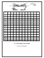
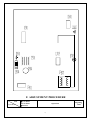
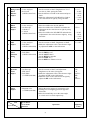
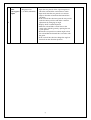
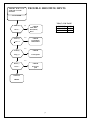
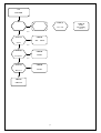
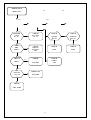
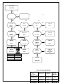
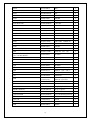
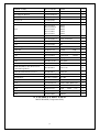
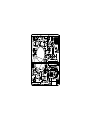
786PF
Service Manual
PROVIEW ELECTRONICS CO.,LTD
6F,No.1,Pau-Sheng Road,Yung-Ho City,Taipei 234,Taiwan
Tel : (886-2) 2231-6789 , Fax :(886-2) 2231-5678
1
TABLE OF CONTENTS
SERVICE WARNING·····································1
A. I M P O R T A N T S A F E T Y I N S T R U C T I O N · · · · · · · · · · · · · · · · · · · · · 1
B. S P E C I F I C A T I O N S · · · · · · · · · · · · · · · · · · · · · · · · · · · · · · · · · · · · 2
C. T I M I N G C H A R T · · · · · · · · · · · · · · · · · · · · · · · · · · · · · · · · · · · · · · 5
D. C O N T R O L L O C A T I O N · · · · · · · · · · · · · · · · · · · · · · · · · · · · · · · · · 6
E. A D J U S T M E N T C O N T R O L L O C A T I O N · · · · · · · · · · · · · · · · · · · · · 7
F. A D J U S T M E N T P R O C E D U R E · · · · · · · · · · · · · · · · · · · · · · · · · · · · 8
G. B L O C K D I A G R A M · · · · · · · · · · · · · · · · · · · · · · · · · · · · · · · · · · · 1 3
H. T R O U B L E S H O O T I N G H I N T S · · · · · · · · · · · · · · · · · · · · · · · · · · · 1 9
I. R E P L A C E M E N T P A R T S L I S T · · · · · · · · · · · · · · · · · · · · · · · · · · · 2 7
J. C O N D U C T I O N V I E W · · · · · · · · · · · · · · · · · · · · · · · · · · · · · · · · · 5 9
K. SCHEMATIC DIAGRAM·······························61
WARNING
2
To prevent from fire or shock hazard,do not expose monitor to any rain or any form of water.High
voltage is inside the monitor so please do not remove the back cover of the cabinet if you are not a qualified
monitor engineer.
Contact the local dealer or the nearest MAG branch office if you need help.
A. IMPORTANT SAFETY INSTRUCTION
Prior to using this service manual,please ensure that you have carefully followed all the procedures outlined in
the user's manual for this product.
1. Read all of these instructions.
2. Save these instructions.
3. Follow all warnings and instructions a marked on the product.
4. Unplug this product from the wall outlet before cleaning.Do not use liquid cleaners or aerosol
cleaners, use a damp cloth for cleaning.
5. Do not use this product near water.
6. Do not place this product on an unstable cart,stand or tablle.The product may fall,causing serious
damage to the product.
7. Slots and openings in the cabinet and the back or bottom are provided for ventilation,to ensure
reliable operation of the product and to protect it from overheating,those openings must not be
blocked or covered.The openings should never be blocked by placing the product on a bed,sofa, rug,
or other similar surface.This product should not be placed in a built-in installation less proper
ventilation is provided.
8. This products should be operated from the type of power source indicated on the marketin label.
If you are not sure of the type of power available, consult your dealer or local power company
9. This product is equipped with a 3-wire grounding type plug,a plug having a third (grounding)
pin.This plug will only fit into a grounding-type power outlet.This is a safety feature,if you are
unable to insert the plug into the outlet,contact your electrician to replace your obsolete outlet.Do
not defeat the purpose of the grounding-type plug.
10. Do not allow anything to rest on the power cord.Do not locate this product where persons will walk
on the cord.
11. If an extension cord is used with this product,make sure that the total of the ampere ratings on the
product plugged into the extension cord to the waplugged into outlet does not exceed 15 ampere.
12. Never push objects of any kind into this product through cabinet slots as they may touch dangerous
voltage points or short out parts that could result in a risk of fire or electric shock.Never spill liquid
of any kind on the product.
13. Do not attempt to service this product yourself,as opening or removing covers may expose you to
dangerous voltage points or other risks.Refer all servicing to service personnel.
14. Unplug this product from the wall outlet and refer servicing to qualified service personnel under the
following conditions.
a. When the power cord or plug is damaged or frayed.
b. If liquid has been spilled into the product.
c. If the product has been exposed to rain or water.
d. If the product does not operate normally,when the operating instructions are followed.Adjust
only those controls that are covered by the operating instructions since improper adjustment of
other controls may result in damage and will often require extension work by a qualified
technician to restore the product to normal operation.
e. If the product has been dropped or the cabinet has been damaged.
f. If the product exhibits a distinct change in performance,indicating a need for service.
For Model 786PF
WARNING : This product included critical components which are essential for X-Radiation safety.
3
See service manual for proper replacement.Maximum 2nd anode voltage must not exceed
30KV at any operating conditions.
To measure 2nd voltage use high impedance meter connect (-) chassis, use a high voltage
lead from (+) to 2nd anode.
VR501,VR601 has been sealed against improper replacement or defeating the control.
Instructions for proper replacement of such sealed controls should also be provided in the
service information.
B. SPECIFICATIONS
786PF
4
17“ 0.25mm dot pitch,Pure Flat Square
Tube,90°deflection, Anti-glare,Anti-static,Anti-reflection.
16.0 inch
310mm (H) × 230mm (V)
1. Screen
2. Visible Image Area
3. Active Display Area
4. Synchronization Range
Horizontal
30 – 86 KHz
Vertical
50 – 160 Hz
100 – 240 Vac , 60/50 Hz
5. Power Source
120W (max.)
6. Power Consumption
7. Input Signal
Video
Analog R.G.B. , 0.7Vp-p / 75 Ohm
Sync.
TTL level,positive or negative polarity
15 Pin D Type
8. Connection Type
1600 × 1200 pixels
9. Resolution
9300ºK / 6500ºK
10. Color Temperature
410 × 418 × 423 (mm)
11. Dimension (W×H×D)
16.8Kg (37.0Lbs)
12. Monitor Weight
13. Base Operation
Tilt
- 5º / + 15º
Swivel
- 45º / + 45º
14. Power Saving
ON
< 120W
OFF
< 5W
15. Signal Connector Pin Assignment
Pin No.
1. Red
6. Red Ground
11. Ground
2. Green
7. Green Ground
12. SDA
3. Blue
8. Blue Ground
13. Horizontal Sync.
4. Ground
9. Not Connected
14. Vertical Sync.
5. Self Test
10. Sync. Ground
15. SCL
C. TIMING CHART
A : Period
B : Active
C : Sync Width
Video
5
D
B
D : Back Porch
E : Front porch
E
Sync.
C
A
Preset
Modes
Dot Rate
(MHz)
F.H
(KHz)
A- Period
(uS)
B- Active
(uS)
C- Sync
(uS)
D-Back
Porch (uS)
E-Front
Porch (uS)
F.V
(Hz)
A- Period
(Ms)
B- Active
(mS)
C- Sync
(mS)
D-Back
Porch (mS)
E-Front
Porch (mS)
H/V
SYNC
Interlaced
VGA
640
×
480
VGA
720
×
400
VESA
800
×
600
VESA
640
×
480
XGA
1024
×
768
SIEMENS
VESA
800
×
600
VESA
1024
×
768
SIEMENS
640
×
480
800
×
600
VESA
1024
×
768
VESA
1280
×
1024
25.175
28.322
40.000
36.000
65.000
40.500
56.25
78.750
67.5
94.5
135
31.469
31.469
37.879
43.269
48.363
50.600
53.674
60.023
63.92
68.677
79.976
31.778
31.778
26.400
23.111
20.677
19.752
18.631
16.660
15.644
14.561
12.504
25.422
25.422
20.000
17.778
15.754
15.802
14.222
13.003
11.852
10.836
9.481
3.813
3.813
3.200
1.556
2.092
1.58
1.138
1.219
0.948
1.016
1.067
1.907
1.907
2.200
2.222
2.462
1.975
2.702
2.235
2.370
2.201
1.837
0.318
0.318
1.000
1.556
0.369
0.395
0.569
0.203
0.474
0.508
0.119
59.941
70.087
60.317
85.0
60.004
100.1
85.061
75.029
100.0
84.997
75.025
16.683
14.268
16.579
11.764
16.666
9.995
11.756
13.328
9.997
11.765
13.329
15.253
12.711
15.840
11.093
15.880
9.481
11.179
12.795
9.387
11.183
12.804
0.064
0.064
0.106
0.069
0.124
0.059
0.056
0.050
0.047
0.044
0.038
1.049
1.112
0.607
0.578
0.600
0.435
0.503
0.466
0.548
0.524
0.475
0.254
0.222
0.026
0.023
0.062
0.02
0.019
0.017
0.016
0.015
0.013
-. -
-.+
-. -
+.+
-. -
-. -
+.+
+.+
+.+
+.+
+.+
NON
NON
NON
NON
NON
NON
NON
NON
NON
NON
NON
D. CONTROL LOCATION
Font control panel
6
a. Power Switch
b. Power Indicator
c.Encoder
d. Enhance Key
E. ADJUSTMENT CONTROL LOCATION
7
IC601
VR501
Q504
VR601
IC901
L705
T501
C504
Q703
FBT
F501
F. ADJUSTMENT PROCEDURE
ITEM
Program Menu.
﹟Test Meter
﹡Test Point
﹫Pattern
Operation
8
Adjusting
Value
B+
Adjust
A
﹟Digital Voltmeter
﹡D510 Negative
﹫Crosshatch Pattern
(31.5KHz,640x480)
1. Make the adjustment to the value shown at right
by turning the VR501 on the main PCB.
High Voltage ﹟Digital Voltmeter
1. Turn the power switch of the monitor OFF.
Adjust
2. Connect high voltage probe to Anode Cap and
﹟High Voltage
GND.
Probe
3. Turn the power switch of the monitor ON.
﹡Anode Cap-GND
B
(15 minutes)
﹫Crosshatch Pattern
4.
Make
the adjustment to the value shown at right
(31.5KHz,640x480)
by turning the VR601 on the main PCB.
Preset
Adjust
﹫Crosshatch
(31.5KHz,640x480)
C
ITEM
Program Menu.
1. Turn the power switch of the monitor OFF.
2. Hold encorder key,then turn the power switch of
the monitor ON.
3. Turn encorder key,make sure into preset picture,
if not ,please return 1-2.
4. Please following the procedure of selection and
adjusting an item using the OSD system as below
steps for main function adjusent.
Step 1 : Press and relese the OSD control knob to
activate the OSD menu.
Step 2 : Turn the knob to highlight the desired option
of OSD icon.
Step 3 : Press and release the knob again to access
the option. The color of the inner area of the
OSD will changed from blue to green.
Step 4 : To make your adjustment,turn the knob
Clockwise to increase or countclockwise
to decrease the setting.
Step 5 : Press and release the knob again to store
the change.the color of the inner area will
go back to blue.You can select EXIT icon
and press the knob the exit the OSD menu.
﹟Test Meter
﹡Test Point
﹫Pattern
Operation
9
15.5V
±0.2V
26.0KV
Contrast :
MAX.
Brightness
MAX.
H-Size :
310mm
V-Size :
230mm
H-Posi. :
Center
V-Posi :
Center
Adjusting
Value
Background ﹟Color Analyzer
White
﹫R.G.B off
Balance
(68KHz,1024x768)
D Adjust
White
Balance
Adjust
E
F
﹟Color Analyzer
﹟Oscilloscope
﹡Cathode G
﹫3” block
(68KHz,1024x768)
1. Set the contrast to MAX.,Brightness to Y=0.7
set color is 9300°K using the OSD.
2. Set the OSD to COLOR of sub menu and press
knob.
3. Make the adjustment R.G.B BIAS low light to
the value shown at right by using encorder.
1. Move the OSD to the R.G.B. DRIVE.
2. Move the OSD to the G DRIVE and make the
adjustment to the value shown at right by using
encorder.
3. Move the OSD to the R,B-DRIVE and make the
Adjustment to the value shown at right by using
Encorder.
ABL
Adjust
﹟Color Analyzer
1. Set the contrast to MAX.,Brightness to MAX.
2. Make the adjustment to the value shown at right
﹫Full White
by adjustment ABL on the OSD menu.
(64KHz,1280x1024)
Other
Function
Seting
﹫Full White
1. Set the FREQ. to 87
(64KHz,1280x1024) 2. Set the OSD to MAG
3. Set the BURN to Disable
4. Set the TIME to 15
5. Set the DEFO to TDA9113/9112
G
Dynamic
Focus
H Adjust
Purity
Adjust
﹟Oscilloscope
﹡FBT Pin14
﹫Full White
(31.5KHz,640x480)
1. Set the contrast to MAX.,and adjustment
Brightness to the raster just appear.
2. Make the adjustment to the value shown at right
by adjust the VF on the OSD menu.
3. Make the check to the value shown at right by
adjust the HF on the OSD menu.
﹫Magenta color
(31.5KHz,640x480)
1. Adjust the purity magnet is in magneta color.
2. Turning two overlapping pawels in opposite
directions.
3. Move them until they are at the same angle,
9 o’clock and 3 o’clock respectively.
I
ITEM
Program Menu.
﹟Test Meter
﹡Test Point
﹫Pattern
Operation
10
Y = 0.7
±0.1FL
x = 0.283
±0.01
y = 0.297
±0.01
37VP-P
x = 0.283
±0.01
y = 0.297
±0.01
Y = 33FL
VF :
140
±10VP-P
HF :
430
±10VP-P
Adjusting
Value
﹫Magenta color
Static
Convergence (31.5KHz,640x480)
Adjust
J
1. Open the two pawels of the 4 pole magnets to
allow the red and blue vertical lines to unite.
2. Open and rotate the two pawels at a contrast
angle so that the red and blue horizontal lines
can unite.
3. If the vertical lines deviates,open the two powals
at the deviation position and make a monitor
adjustment by changing its angle.
4. Display white crosshatch pattern.
5. Make the red and blue vertical lines at the
center unite with the green by opening the two
6 pole pawels.
6. Rotate the two pawels at contrast angle so that
the red and blue horizontal lines can unite with
the green.
7. If the vertical lines deviate,change the angle of
Pawels from the deviation position.
11
12
13
G. BLOCK DIAGRAM
14
15
16
17
18
19
H. TROUBLE SHOOTING HINTS
BRIGHT HOR. LINE
APPEAR ON THE
SCREEN
NO POWER
T501(7) VOLTAGE
No
T501 (7)
No
160 V ?
AC120V IN
AC220V IN
AC230V IN
CHECK
F501,D514 ,
D515,D516,
D517
Yes
IC501 (7)
No
> 14 V ?
CHECK
IC501,R539,
D505,ZD551
Yes
No
IC501(6)
CHECK
14Vp-p ?
IC501,Q504
Yes
No
D510 (-)
CHECK
15.5V ?
D510,Q501,
Q508
Yes
CIRCUIT
SHORT
20
160V
294V
308V
NO
RASTER
No
IC301
CRT G1
(2)
-20V~
Yes
-80V ?
12 V ?
Q710
(E)
CHECK
15V
LINE
-0.6V ?
IC901(4)
-1.5V~-1.8V
No
IC301 (4)
Yes
CHECK
-12V
-12 V ?
LINE
No
IC301 (1)
CHECK
Yes
0.7 VP-P ?
IC301 (5)
Yes
48 VP-P ?
IC601
No
CHECK
IC301
CHECK
CRT DY
21
CHECK
IC901
Surrounding
CKT
DEFLECTIVE
HOR. CKT
No
No
Yes
No
Yes
No
Yes
HEATER
VOLT
6.3 V ?
No
No
Yes
CHECK
CHECK
B+ VOLT
7.2 V ?
No
CHECK
Q711(B)
< 0.7 V ?
IC901(24)
> 2.0 V ?
CHECK
Deflection
Horizontal
CKT
CHECK
CHECK
IC601
IC901
CHECK
CHECK
VIDEO
CKT
Yes
CRT
EHT
26KV ?
Yes
CRT G2
600V ?
No
No
T701 FBT
Yes
CRT
KR,KG,KB
VIDEO CKT
VOLTAGE
?
FAILURE
CHECK
CRT TUBE
22
OFF MODE
Yes
FAILURE
No
IC901(40)
Q703
o (C)
1.0
(41)~ 1.2
H/V
KSIGNAL
VP-P?
?
Yes
CHECK
No
Yes
NO RASTER
PC
No
Yes
Q703 (B)
DRIVE
PULSE
No
No
Q703
T701 (3)
FAILURE
B+ ?
Yes
No
CHECK
FBT
Yes
No
Yes
Q702 (G)
REPLACE
CHECK
CHECK
DRIVE
PULSE
Q703
B+ 51V
B+ 51V
No
Yes
No
No
CHECK
IC601
CHECK
Q719,(G)
CHECK
DRIVE
PULSE?
Yes
B+ = 15V?
986N:T701(3) Voltage for each mode
Fh
T701(3) B+
31.5KHz
63V
CHECK
CHECK
37KHz
77V
48KHz
93V
15V LINE
T702
54KHz
104V
56KHz
111V
64KHz
127V
68KHz
139V
75KHz
153V
80KHz
166V
86KHz
181V
Q719
Q601,
Q602 (B)
CHECK
IC601
BOUT
SURRONDING
CKT
CHECK
Q601,Q602
VESA STANDARD DPMS
ITEM
H/V Sync.
VIDEO
LED
GREEN
NORMAL
ON/ON
NORMAL
ON
STAND BY
OFF/ON
OFF
FLICKER
MODE
23
Yes
NO ROTATION
No
P903
No
OK ?
Yes
No
IC901(20)
CHECK
PS 0
0V?
Yes
IC901
No
Q505 (C)
CHECK
Q505
7.0 V Yes
?
CHECK
Q511 (B)
CHECK
IC901
0V?
CHECK
Q511
No
24
NO CHARACTERS
Yes
MISSING ONE
COLOR
No
CRT KG
Yes
80V0-P?
CHECK
NO
RASTER
Rotation Coil
No
IC203
Q902 (c)
(3)
Yes
P-P? ?
3915VV
CHECK
No
R979Yes
15V
IC203
LINE
CHECK
7V?
No
7V LINE
Q902 (B)
Yes
Q903 (B)
1.5~13V ?
CHECK
Q902
Q903
Q904 (B)
CHECK
0~2.5V ?
IC901
CHECK
Q904
Example:Missing Green
No
Yes
25
OSD DOES NOT
WORK
No
Yes
IC201 (19)
OSD G
5V0-P?
No
IC201(24)
CHECK
7V ?
IC201
Yes
IC202 (3)
No
5 V0-P ?
CHECK
M703
BLK ?
Yes
IC203
(8)
12 V ?
No
CHECK
12V
Yes
IC201
(10)
5V ?
No
CHECK
IC201
Yes
IC201 (7)
CHECK I/P
SIGNAL
0.7VP-P ?
IC201
(19)
CHECK
IC901
(32)
: Missing Green
0.4 V ?Example
Condition : OSD on
Yes
Yes
CHECK
IC201
No
No
Yes
26
No
Yes
No
IC202(6)
CHECK
4.2VP-P ?
80V ?
CHECK
D203
I. REPLACEMENT PARTS LIST
786PF
Spare Parts List
Location.
REV:A
Parts Number
Parts Description
Q’ty
R631
210-100-0256
10Ω
1/2W
1
R734
210-100-0256
10Ω
1/2W
1
R762
210-100-0456
10Ω
1/4W
1
R7A2
R612,611,663,912,918,926,927,976
R977
210-100-0856
10Ω
1/8W
1
210-101-0456
100Ω
1/4W
9
27
R205,235,265,281,284,285,516,664
R711A,918A,942,943,952,953,982
R984,985
R703
210-101-0856
100Ω
1/8W
17
210-101-0856
100Ω
1/8W
1
R736
210-102-0256
1KΩ
1/2W
1
R525,740,754,7A8
210-102-0456
1KΩ
1/4W
4
R210,240,270,533,546,626,755,793
R974,993
210-102-0856
1KΩ
1/8W
10
R991
210-102-0856
1KΩ
1/8W
1
R529,536,610,983
210-103-0456
10KΩ
1/4W
4
R288,291,510,590, 606,615, 630, 651
R730,931,947
210-103-0856
10KΩ
1/8W
11
R710
210-203-0856
20KΩ
1/8W
1
R724
210-103-0856
10KΩ
R797A
210-103-0856
10KΩ
1/8W
1
R2A3,770
210-104-0256
100KΩ
1/2W
2
R508,731
210-104-0456
100KΩ
1/4W
2
R725
210-104-0456
100KΩ
1/4W
1
R767
210-104-0856
100KΩ
1/8W
1
R757
210-105-0456
1MΩ
1/4W
1
R745
210-112-0856
1.1KΩ
1/8W
1
R737
210-134-0456
130KΩ
1/4W
1
R929
210-683-0456
68KΩ
1/4W
1
R303
210-123-0456
12KΩ
1/4W
1
R666
210-223-0856
22KΩ
1/8W
1
R768
210-133-0856
13KΩ
1/8W
1
R761
210-272-0456
2.7KΩ
1/4W
1
R602
210-153-0456
15KΩ
1/4W
1
R608
210-153-0856
15KΩ
1/8W
1
R515,589
210-154-0856
150KΩ
1/8W
2
R614
210-182-0856
1.8KΩ
1/8W
1
R797A
210-183-0856
18KΩ
1/8W
1
R914
210-203-0456
20KΩ
1/4W
1
R629
210-203-0856
20KΩ
1/8W
1
R307,732
210-2R2-0456
2.2Ω
1/4W
2
R2A7
210-220-0456
22Ω
1/4W
1
R207,237,267,
210-221-0256
220Ω
1/2W
3
R534
210-221-0456
220Ω
1/4W
1
R205,235.265,910,911
210-221-0856
220Ω
1/8W
5
R741
210-222-0856
2.2KΩ
1/8W
1
28
1/8W
1
R706,708
210-222-0856
2.2KΩ
1/8W
2
R535,654,728
210-223-0856
22KΩ
1/8W
3
R667
210-223-0856
22KΩ
1/8W
1
R723
210-223-0856
22KΩ
1/8W
1
R717
210-223-0856
22KΩ
1/8W
1
R794A
210-245-0856
2.4MΩ
1/8W
1
R308
210-471-0256
470Ω
1/2W
1
R521,713
210-271-0456
270Ω
1/4W
2
R670,7A1
210-302-0856
3.0KΩ
1/8W
2
R514
210-303-0456
30KΩ
1/4W
1
R979
210-330-0456
33Ω
1/4W
1
R7A6
210-331-0856
330Ω
1/8W
1
R601,665
210-332-0856
3.3KΩ
1/8W
2
R604
210-332-0856
3.3KΩ
1/8W
1
R707
210-332-0856
3.3KΩ
1/8W
1
R603
210-333-0456
33KΩ
1/4W
1
R588
210-333-0856
33KΩ
1/8W
1
R7A7
210-334-0256
330KΩ
1/2W
1
R733
210-334-0456
330KΩ
1/4W
1
R207,237,267
210-334-0856
330KΩ
1/8W
1
R724,730
210-363-0856
36KΩ
1/8W
2
R544
210-363-0456
36KΩ
1/4W
1
R287
210-390-0256
39Ω
1/2W
1
R765
210-392-0856
3.9KΩ
1/8W
1
R7A3,928
210-393-0856
39KΩ
1/8W
2
R615
210-103-0856
10KΩ
1/8W
1
R588
210-433-0856
43KΩ
1/8W
1
R712
R202,232,262,551,726,729
L200,L230,L260
R726
210-4R7-0456
4.7Ω
1/4W
1
210-470-0856
47Ω
1/8W
9
210-470-0856
47Ω
1/8W
1
R908
210-471-0456
470Ω
1/4W
1
R771
210-471-0856
470Ω
1/8W
1
R509,532,617,618, 903
210-472-0456
4.7KΩ
1/4W
5
R980
210-472-0456
210-472-0456
622-10a-9101
4.7KΩ
4.7KΩ
Jumper
1/4W
1/4W
1
210-472-0856
4.7KΩ
1/8W
11
210-472-0856
4.7KΩ
1/8W
1
210-472-0856
4.7KΩ
1/8W
1
R901
R283,2A8,620,653,727,741,933,934,
R975,989,994
R718
R992,716,722,722A
29
1
R619,669
210-473-0456
47KΩ
1/4W
2
R290,507,522,622,932,940,941,
210-473-0856
47KΩ
1/8W
7
R501
210-474-0256
470K
1/2W
1
R206,236,266,2A2
210-510-0256
51Ω
1/2W
4
R739,760
210-512-0856
5.1KΩ
1/8W
2
R2A6
210-513-0856
51KΩ
1/8W
1
R905
210-561-0456
560Ω
1/4W
1
R920
210-561-0856
560Ω
1/8W
1
R334
210-562-0456
5.6KΩ
1/4W
1
R290.292.294.295
210-562-0856
5.6KΩ
1/8W
4
R604
210-562-0856
5.6KΩ
1/8W
1
R668
210-563-0456
56KΩ
1/4W
1
R292
210-622-0856
6.2KΩ
1/8W
1
R738
210-562-0856
5.6KΩ
1/8W
1
R520
210-6R8-0456
6.8Ω
1/4W
1
R791
210-682-0856
6.8KΩ
1/8W
1
R746
210-682-0856
6.8KΩ
1/8W
1
R588
210-683-0856
68KΩ
1/8W
1
R744
210-683-0856
68KΩ
1/8W
1
R201.231.261
210-750-0856
75Ω
1/8W
3
R981
210-752-0456
7.5KΩ
1/4W
1
R652
210-822-0856
8.2KΩ
1/8W
1
R766
210-682-0856
6.8KΩ
1/8W
1
R616
210-823-0856
82KΩ
1/8W
1
R605
210-823-0856
82KΩ
1/8W
1
R539
210-9R1-0256
9.1Ω
1/8W
1
R703A
213-1R0-1059
1.0Ω
R-NF
1W
1
R2A1
213-2R2-1059
2.2Ω
R-NF
1W
1
R2A4
213-7R5-1059
7.5Ω
R-NF
1W
1
R758
213-102-2059
1KΩ
R-NF
2W
1
R326
213-R91-1055
0.91Ω
R-MNF
1W
1
R502,504
213-823-2059
82KΩ
R-MNF
2W
2
R732
214-2R2-0259
2.2Ω
R-FR
1/2W
1
RP901
216-472-0457
4.7KΩ
±5%
R-NW
1
NTC501
218-7R0-0871
7Ω
8A
NTC
1
PTC501
219-9R0-0171
9Ω
PTC
1
R711
220-150-2059
15Ω
R-MNF
2W
1
R704
220-331-2059
330Ω
R-MNF
2W
1
R777
220-2R2-1059
2.2Ω
R-MNF
1W
1
30
R513
220-2R7-3059
2.7Ω
R-MNF
3W
1
R714
220-R47-3059
0.47Ω
R-MNF
3W
1
R623
220-4R7-2059
4.7Ω
R-MNF
2W
1
R528
220-561-1059
560Ω
R-MNF
1W
1
R503
220-753-3059
75KΩ R-MNF
3W
1
R705
220-8R2-2059
8.2Ω
2W
1
R609
221-081-1152
11.5KΩ
1%
1/8W
1
R749
221-081-2400
240Ω
1%
1/8W
1
R747
221-081-2702
27KΩ
1%
1/8W
1
R752
221-081-3003
300KΩ
1%
1/8W
1
R751
221-081-3003
300KΩ
1%
1/8W
1
R302
221-081-3572
35.7KΩ
1%
1/8W
1
R753
221-081-3242
32.4KΩ
1%
1/8W
1
R748
221-081-5101
5.1KΩ
1%
1/8W
1
R613
221-081-5621
5.62KΩ
1%
1/8W
1
R333
221-081-5761
5.76KΩ
1%
1/8W
1
R750
221-081-6190
619Ω
1%
1/8W
1
PTC502
222-040-7200T
Polyswitch
0.4A/72V
1
VR501,VR601
231-202-0677
2K,VR
R526
232-R22-2059
0.22Ω
R-WR
2W
1
R759
232-R30-3059
0.3Ω
R-WR
3W
1
C935,948
300-1R0-5020
1.0u
50V
E.C
2
C949
300-1R0-5020
1.0u
50V
E.C
1
C205,235,265
300-1R0-0122
1.0u
100V
E.C
3
C922
300-100-1620
10u
16V
E.C
1
C270,274,582,704,907
300-100-5020
10u
50V
E.C
5
C725
300-100-5020
10u
50V
E.C
1
C275,276,278
300-100-0120
10u
100V
E.C
3
C722
300-100-0423
10u
250V
E.C
1
C505,507,527,601
300-101-1623
100u
16V
E.C
4
C523
300-101-2520
100u
25V
E.C
1
C325,703
300-101-3520
100u
35V
E.C
2
C525
300-102-1623
1000u
16V
E.C
1
C323,520
300-102-2523
1000u 25V E.C 105 C
1
C206,236,266
300-R22-0122
0.22u
E.C
1
C716
300-2R2-0423-SL
2.2u
250V E.C
Lesr
1
C623,742
300-220-1620
22u
16V
E.C
2
C520
300-220-0222
22u
160V
E.C
1
C504
300-221-0522
220u
400V
E.C
1
31
R-MNF
2
100V
C521
300-331-0123
330u 100V E.C 105C
1
C510,612,613,715,774, 901
300-4R7-5020
4.7u
50V
E.C
6
C773
300-4R7-5020
4.7u
50V
E.C
1
C772
300-4R7-5020
4.7u
50V
E.C
1
C272,2A4,607,615
300-470-1620
47u
16V
E.C
4
C745
300-470-1620
47u
16V
E.C
1
C744
300-470-0120
47u
100V
E.C
1
C501,519,305
300-471-2520
470u
25V
E.C
3
C701
300-6R8-5020
6.8u
50V
E.C
1
R545
300-680-3520
68u
35V
E.C
1
C609
305-103-0550
0.01u
50V
PE
1
C292,626,627,628,629,905,906,914
C915,916,917
307-101-1170
100p
50V
C.C
11
C518,618A,771,740A
307-102-1160
1000p
50V
C.C
4
C2A2
307-102-3570
1000p
500V
C.C
1
C602,778,779
307-103-1170
0.01u
50V
C.C
3
C277,2A7,506,515,528,746,747
307-103-3570
0.01u
500V
C.C
7
C714
307-103-3570
0.01u
500V
C.C
1
C603,622
307-104-1770
0.1u
50V 10% C.C
2
C614
307-221-1170
220p 50V 10% C.C
1
C517,551,552,733
307-221-3570
220p
500V
C.C
4
C718
307-221-3570
220p
500V
C.C
1
C294
307-182-1170
1800p
50V
C.C
1
C550,625,705
307-222-1170
2200p
50V
C.C
3
C776
307-222-1170
2200p
50V
C.C
1
C726
307-222-3570
2200p
500V
C.C
1
C618
307-223-1170
0.022u
50V
C.C
1
C515
307-223-3570
0.022u
500V
C.C
1
C2A9
307-330-1170
33p
50V
C.C.
1
C509,751,752
307-331-1170
330p
C748,749,912,911
307-471-1170
470p
10% C.C
4
C526,741
307-471-3570
470p 500V 10% C.C
2
C780
307-822-1170
8200p 50V 10% C.C
1
C2A3
307-472-6570
4700p
2KV
C.C
1
C583
307-561-1160
560p
50V
C.C.
1
C740
308-301-1152
300p 50V C.C. NPO
1
C918,919
308-470-1150
47p
50V C.C. NPO
2
C792
308-101-6860
100p 2KV 10% C.C
1
C732
309-102-1552
1000p 1.5KV
PHM
1
C713
309-332-1052
3300p
PHM
1
32
50V
50V
1KV
C.C.
3
C712
309-432-1552
4300p 1.5KV
PHM
1
C620,790
310-104-0252
0.1u
250V
MEM
2
C710
310-823-0252
0.082u
250V
MPP
1
C716
310-225-0252-H
2.2u
250V
MPP
1
C717
310-224-0452
0.22u
400V
MPP
1
C709
310-274-0252
0.27u
250V
MPP
1
C731
310-824-0452
0.82u
250V
MPP
1
C508,524
315-224-2572
0.22u
250V
X-CAP
2
C502,503,555
317-222-4072
2200p
400V
Y-CAP
3
C619
318-102-0550
1000p
50V.
MEM
1
C611
318-103-0550
0.01u
50V.
MEM
1
C310,608,721
318-104-0550
0.1u
50V
MEM
3
C620,790
318-104-0250
0.1u
250V
MEM
2
C727
318-105-1052
1u
100V
MEM
1
C793
318-152-0152
1500p
100V.
MEM
1
C605
318-154-0550
0.15u
50V
MEM
1
C307
318-224-0550
0.22u
50V
MEM
1
C606
318-474-0550
0.47u
50V
MEM
1
C309
318-682-0550
6800p 50V 10% MEM
1
C719,720
319-101-1060
100p
2
C522
319-221-1060
220p 1KV 10% C.C
1
C516
326-222-0520
2200p 50V
2% PL
1
C610
326-821-0520
820p
2% PL
1
C201,231,261,701
328-103-2260
0.01u
50V
C.C
4
C777
328-103-2260
0.01u
50V
C.C
1
C708,778
C271,291,293,295,202,232,262,2A1,
C2A5,2A6,603,622,616,513,903,904,
C 908,909,920,921,902A,902B,724
C702,730
328-103-2260
0.01u
50V
C.C
2
328-104-2690
0.1u
50V
C.C
23
328-104-2690
0.1u
50V
C.C
2
SW902,903
401-170-D200
Tact Switch
2
SW901
401-240-0501
Encoder
1
SW501
401-270-0402
Soft Power Switch
1
RL501
402-001-212DM
DSA-SS-212DM5 Relay
1
RL701
402-001-212DM5
DSA-SS-212DM5 Relay
1
JK302
409-003-0104A
Phone Jack 3Pin
1
JK301
409-003-0201A
DC Jack 3Pin
1
IC902 Socket
410-008-0102
IC902 Socket 8Pin
1
CRT SOCKET (17”)
411-100-0006
CRT Socket
1
P501
412-600-0001
AC Inlet Socket
1
33
1KV
50V
C.C
SG281
430-301-0001
300V
1
IC902
501-000-2408
AT24C08
1
IC901
503-100-62P2-P
CPU
1
IC201
504-550-1237
LM1237
1
IC202
504-000-2480
LM2480
1
IC203
504-000-2469
TDA2469
1
IC203 Heat Sink
123-003-P6SE-E
IC203 H.S
1
IC301
504-900-8172
TDA8172
1
IC301 Heat Sink
120-002-P6SE-B
IC301,H.S
1
Silicon Rubber
120-100-2001
For IC301
1
Shoulder Washers
540-500-2002C
For IC301
1
IC501
504-200-3842A
KA3842A
1
IC502
505-1R5-7812
LM7812
IC503
505-093-76285
AMC76289 300mA/5V
1
IC601
504-700-9116
TDA9116
1
IC203
504-000-2469
LM2469
1
Q281,602,653,714,715,903
510-000-0733
2SA733
6
Q505
Q502,508,511,513,601,606,651,708
Q711,722,902,904,907
Q710
510-010-772SP
HSB772S (TO – 92)
1
510-023-0945
2SC945P
13
510-200-0423
BF423
1
Q702
511-001-2865
2SK2865
1
Q704, 725
510-023-0945
2SC945P
2
Q706
510-023-0945
2SC945P
1
Q726
510-023-0945-P
2SC945P
1
Q501
510-010-0772
HSB772
(TO – 126 )
1
Q701
510-010-0772
HSB772
(TO – 126 )
1
Q713
HMPSA44
2SK2141
2SK2746 (For PFC)
Q504 Heat Sink
1
Q504 Heat Sink
510-300-SA44
511-001-2141
511-001-2746
120-001-P6SE-
Q717
510-250-0122
TIF122
1
Silicon Rubber
540-100-2001
For Q717,Q719,D719
1
Shoulder Washers
540-500-2002-C
For Q717,Q719
1
Q703
510-023-5411
2SC5411
1
Q703 Heat Sink
120-001-P6SE-E
Q717,703,D709,Q719 H.S
1
Q707
511-005-0644
IRF644
1
Q719,709
511-005-0634
IRF634
2
LED901
520-005-73GD
5ψ LED
1
D304
520-010-4002
1N4002
1
Q504
34
(TO-220)
1
1
1
D201,231,261,202,232,262,203,233
D263,503,507,518,532,601,602,603
D604,606,610,611,711A,713,714,716
D720,725,752,753, 901,902,904
D605
520-001-4148
1N4148
31
520-001-4148
1N4148
1
D703,704
520-001-4148
1N4148
2
D505,712,715,708
520-010-4936
1N4936
4
D707
520-010-4936
1N4936
1
D711
520-010-4937
1N4937
1
ZD702
521-005-03R6
HZ4A2 (3.6V)
1
ZD281,701,901,902,903,904.281
521-005-05R0
HZ5C1
7
ZD601,612
521-005-13R0
HZ13V
2
ZD551
521-005-18R0
HZ18V
1
ZD502
521-005-30R0
HZ30V
1
ZD501
521-005-56R0
HZ56V
1
D205.235.265
522-010-SS83
1SS83
3
D501
522-010-T42M
BYT42M
1
D513
522-020-H203
HER203
1
D508
522-020-H207-F
HER207G-F
1
D514,515,516,517
522-020-L205
RL205
4
D502,510
522-030-H303G-F HER303G
2
D719
522-030-H305G-F HER305G
1
D509
522-030-H305G
HER305G
1
D509 Heat Sink
120-001-0916-C
D509 Heat Sink
1
D709
522-050-023M
ESC023M-15
1
D705
522-010-5818
1N5818
1
X901
530-120-0001
RESONATOR,12MHz
1
F501
550-141-3000
3.15A,250V
1
FUSE CLIP
551-021-0001
Wire
620-040-0200
G3 to G3’
P502
630-002-2002
2P
1.56D
Base
1
P701
630-004-3001
4P
2.36D
Base
1
P281,505,TCO
630-001-3001
1P
2.36D
3
P601
630-002-1009
For X-Ray Test
1
P301,901
630-002-4001
2P
2
P902
630-005-4001
For Signal Cable
1
P903
630-003-4003
3P
Pitch 2.5mm
1
P905
630-009-1009
9P
Pitch 2.0mm
1
P201
630-006-4001R
6P
2.0mm
Base
1
P202
630-012-1009
12P
2.0mm
Base
1
35
2
1
0.6D
POWER CORD
600-151-2804D
150mm
1
SIGNAL CABLE
610-171-15801
Signal Cable
1
Rear Support Bracket
121-001-P6SE-B
1
Rear Bracket
121-002-P6SE-A
1
CRT Cover
123-004-P6SE
1
CRT DY Cover
T703
123-002-768I-A
700-119-246P
700-117-25PF-2
700-117-26SS
700-117-2806
700-115-2823
730-400-770VC
For TCO
986NS
787NS
786NS
772NS
562NS
Focus choke
1
T501
730-102-P6SE-A
Power Converter
1
T702
730-200-770VC
H-Driver
1
T701
730-302-P6SE
FBT
1
Degaussing Coil
735-017-X771-C
L200.260
745-R68-1162
0.68uH
1/2W
2
L230,201,231,261
745-R33-1162
0.33uH
1/2W
4
L703
745-151-2084
H-Size Coil
150uH
1
L704
745-720-2084
Step Up Coil
72uH
1
L502
750-100-770VC
Line-Filter
1
L503
750-150-K998
Line-Filter
1
B280,284,B283,L706,701,511,515,
L900,R585,Q504(G)
760-100-0002
Bead Core
10
L506,507,508,509,510,512,701
760-000-0001
Bead Core
7
L703A
760-100-0001-T
Bead Cord
1
Ground Wire
800-100-772NS-A For CRT
T505
730-122-P7SE-2
PFC Choke
180uF
1
C571
318-684-4052-Y
0.68uF 400V MM-CON
1
C572 ,574
307-103-3572
0.01uF
500V
C.C
2
C573
307-471-3170
470pF
500V
C.C
1
D552
522-023-H308
HER308G
1
D551
522-010-H105
HER105
1
CRT
1
1
J. CONDUCTION VIEW
MAIN BOARD (Component Side)
36
1
1
MAIN BOARD (Soild Side)
37
K. SCHEMATIC DIAGRAM
38
MEMO
42