1
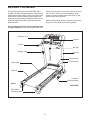
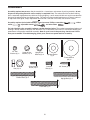
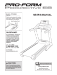
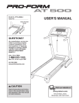
Model No. PATL30506.0
Serial No.
USER'S MANUAL
Serial Number
Decal
QUESTIONS?
If you have questions, or if any
parts are missing or damaged,
PLEASE CONTACT OUR CUSTOMER SERVICE DEPARTMENT
DIRECTLY.
Call toll-free:
800-830-7240
E-mail:
[email protected]
Goodfamily’s Web site:
www.goodfamily.cc
ICON’s Web site:
www.iconfitness.com
CAUTION
Read all precautions and instructions in this manual before using
this equipment. Save this manual
for future reference.
Goodfamily is an authorized dealer of this treadmill in the
territory of mainland China. This treadmill is designed and
manufactured by ICON Health & Fitness, Inc.
TABLE OF CONTENTS
IMPORTANT PRECAUTIONS . . . . . . . . . . . . . . . . . . . . . . . . . . . . . . . . . . . . . . . . . . . . . . . . . . . . . . . . . . . . . . . .3
BEFORE YOU BEGIN . . . . . . . . . . . . . . . . . . . . . . . . . . . . . . . . . . . . . . . . . . . . . . . . . . . . . . . . . . . . . . . . . . . . . .5
ASSEMBLY . . . . . . . . . . . . . . . . . . . . . . . . . . . . . . . . . . . . . . . . . . . . . . . . . . . . . . . . . . . . . . . . . . . . . . . . . . . . . . .6
OPERATION AND ADJUSTMENT . . . . . . . . . . . . . . . . . . . . . . . . . . . . . . . . . . . . . . . . . . . . . . . . . . . . . . . . . . . .13
HOW TO FOLD AND MOVE THE TREADMILL . . . . . . . . . . . . . . . . . . . . . . . . . . . . . . . . . . . . . . . . . . . . . . . . . .18
TROUBLESHOOTING . . . . . . . . . . . . . . . . . . . . . . . . . . . . . . . . . . . . . . . . . . . . . . . . . . . . . . . . . . . . . . . . . . . . .20
CONDITIONING GUIDELINES . . . . . . . . . . . . . . . . . . . . . . . . . . . . . . . . . . . . . . . . . . . . . . . . . . . . . . . . . . . . . . .22
HOW TO ORDER REPLACEMENT PARTS . . . . . . . . . . . . . . . . . . . . . . . . . . . . . . . . . . . . . . . . . . . . .Back Cover
Note: An EXPLODED DRAWING and a PART LIST are attached in the center of this manual.
PROFORM is a registered trademark of ICON IP, Inc.
2
IMPORTANT PRECAUTIONS
WARNING:
To reduce the risk of burns, fire, electric shock, or injury to persons, read the
following important precautions and information before operating the treadmill.
12. Keep the power cord away from heated surfaces.
1. It is the responsibility of the owner to ensure
that all users of this treadmill are adequately
informed of all warnings and precautions.
13. Never move the walking belt while the power
is turned off. Do not operate the treadmill if
the power cord or plug is damaged, or if the
treadmill is not working properly. (See TROUBLESHOOTING on page 20 if the treadmill is
not working properly.)
2. Use the treadmill only as described.
3. Place the treadmill on a level surface, with at
least 2.5 m (8 ft.) of clearance behind it and
0.5 m (2 ft.) on each side. Do not place the
treadmill on any surface that blocks air openings. To protect the floor or carpet from damage, place a mat under the treadmill.
14. Read, understand, and test the emergency
stop procedure before using the treadmill (see
HOW TO TURN ON THE POWER on page 14).
4. Keep the treadmill indoors, away from moisture and dust. Do not put the treadmill in a
garage or covered patio, or near water.
15. Never start the treadmill while you are standing on the walking belt. Always hold the
handrails while using the treadmill.
5. Do not operate the treadmill where aerosol
products are used or where oxygen is being
administered.
16. The treadmill is capable of high speeds.
Adjust the speed in small increments to avoid
sudden jumps in speed.
6. Keep children under the age of 12 and pets
away from the treadmill at all times.
17. The pulse sensor is not a medical device.
Various factors, including your movement,
may affect the accuracy of heart rate readings.
The pulse sensor is intended only as an exercise aid in determining heart rate trends in
general.
7. The treadmill should be used only by persons
weighing 115 kg (250 lbs.) or less.
8. Never allow more than one person on the
treadmill at a time.
18. Never leave the treadmill unattended while it
is running. Always remove the key and unplug
the power cord when the treadmill is not in
use.
9. Wear appropriate exercise clothes when
using the treadmill. Do not wear loose clothes
that could become caught in the treadmill.
Athletic support clothes are recommended for
both men and women. Always wear athletic
shoes; never use the treadmill with bare feet,
wearing only stockings, or in sandals.
19. Do not attempt to raise, lower, or move the
treadmill until it is properly assembled. (See
ASSEMBLY on page 6, and HOW TO FOLD
AND MOVE THE TREADMILL on page 18.)
You must be able to safely lift 20 kg (45 lbs.) to
raise, lower, or move the treadmill.
10. When connecting the power cord (see page
13), plug the power cord into an earthed circuit. No other appliance should be on the
same circuit. When replacing the fuse, an
ASTA approved BS1362 type should be fitted
to the fuse carrier. A 13 amp fuse should be
used.
20. When folding or moving the treadmill, make
sure that the storage latch is fully closed.
21. Inspect and properly tighten all parts of the
treadmill regularly.
11. If an extension cord is needed, use only a 3conductor, 1mm2 (14-gauge) cord that is no
longer than 1.5 m (5 ft.).
22. Never insert any object into any opening.
3
23.
DANGER: Always unplug the power
cord immediately after use, before cleaning
the treadmill, and before performing the
maintenance and adjustment procedures described in this manual. Never remove the
motor hood unless instructed to do so by an
authorized service representative. Servicing
other than the procedures in this manual
should be performed by an authorized service representative only.
24. This treadmill is intended for in-home use
only. Do not use this treadmill in a commercial, rental, or institutional setting.
WARNING:
Before beginning this or any exercise program, consult your physician. This
is especially important for persons over the age of 35 or persons with pre-existing health problems.
Read all instructions before using. ICON assumes no responsibility for personal injury or property
damage sustained by or through the use of this product.
SAVE THESE INSTRUCTIONS
The decals shown at the right have been placed on the treadmill. If a decal is missing, or if it is not legible, call the toll-free telephone number on the front cover of
this manual and order a free replacement decal. Apply the decal in the location
shown. Note: The decals are not shown at actual size.
4
BEFORE YOU BEGIN
Thank you for selecting the new PROFORM® 400 C
treadmill. The 400 C treadmill combines advanced technology with innovative design to help you achieve your
fitness goals in the convenience of your home. And
when you’re not exercising, the 400 C treadmill can be
folded up, requiring less than half the floor space of
other treadmills.
ing this manual, please see the front cover of this manual. To help us assist you, note the product model
number and serial number before contacting us (see
the front cover of this manual).
Before reading further, please familiarize yourself with
the parts that are labeled in the drawing below.
For your benefit, read this manual carefully before
using the treadmill. If you have questions after read-
Accessory Tray
Console
Handrail
Key/Clip
Storage Latch
Upright
On/Off Switch
Circuit Breaker
Walking Belt
Foot Rail
Cushioned
Walking Platform
BACK
RIGHT SIDE
Rear Roller
Adjustment Bolts
5
ASSEMBLY
Assembly requires two persons. Set the treadmill in a cleared area and remove all packing materials; do not
Wheel
Spacerof the treadmill walking
dispose of the packing materials until assembly is completed. Note: The
underside
(94)–4
belt is coated with high-performance lubricant. During shipping, a small amount
of lubricant may be transferred to
the top of the walking belt or the shipping carton. This does not affect treadmill performance. If there is lubricant
on top of the walking belt, simply wipe off the lubricant with a soft cloth and a mild, non-abrasive cleaner.
Assembly requires the included hex keys
mallet
, adjustable wrench
3/4” Tek Screw (58)–8
and your own Phillips screwdriver
, rubber
, and wire cutters
.1/2” Screw (119)–1
For help identifying the assembly hardware, see the drawings below. The number in parentheses below each
drawing is the key number of the part, from the PART LIST in the center of this manual. The number following the
parentheses is the quantity needed for assembly. Note: If a part is not in the parts bag, check to see if it has
been pre-assembled. To avoid damaging plastic parts, do not use power tools for assembly.
1/4” Star
Washer (8)–2
Handrail Star
Washer (11)–4
Upright Star
Washer (6)–4
Upright Washer
(7)–2
Frame Washer
(65)–2
Nut (12)–2
Silver Ground
Screw (10)–2
Console
Bolt (2)–2
Handrail Bolt (9)–4
3/4” Screw (3)–6
Upright Bolt (4)–4
Frame Bolt (1)–2
6
1. Make sure that the power cord is unplugged.
1
Identify the Right Upright (39), which has a
square hole in the location shown.
Orient the Right Upright (39) and the Base (37)
as shown. Attach the Right Upright to the Base
with two Upright Bolts (4) and two Upright Star
Washers (6); do not tighten the Upright Bolts
yet.
39
37
6
4
Square Hole
2. Orient the Left Upright (38) as shown, and attach
it to the Base (37) with two Upright Bolts (4) and
two Upright Star Washers (6); do not tighten
the Upright Bolts yet.
2
Latch
Holes
37
38
6
6
3. Turn the Base (37) over, and set it near the front
of the treadmill as shown.
4
3
39
Wire
Locate the wire in the Right Upright (39). See the
inset drawing. Secure the wire to the connector
on the Upright Wire (69). Then, insert the connector on the Upright Wire into the square hole in
the Right Upright.
37
69
Wire
69
7
4. Raise the Uprights (38, 39).
4
38
See the left inset drawing. Identify the two Frame
Spacers (96). Open the included packet of
grease, and apply grease to both sides of both
Frame Spacers. Next, identify the outer side of
each Frame Spacer.
39
12
Hold a Frame Spacer (96) and a Frame Washer
(65) between the Right Upright (39) and the Lift
Frame (41), with the outer side of the Frame
Spacer facing the Frame Washer and the
Right Upright. Attach the Right Upright to the
Lift Frame with a Frame Bolt (1), an Upright
Washer (7), and a Nut (12); do not tighten the
Nut yet.
7
1
65
41
96
96
39
12
Outer
Side
7
65
Inner
Side
1
96
41
5. Hold the remaining Frame Spacer (96) and
Frame Washer (65) between the Left Upright
(38) and the Lift Frame (41), with the outer side
of the Frame Spacer facing the Frame
Washer and the Left Upright. Attach the Left
Upright to the Lift Frame with a Frame Bolt (1),
an Upright Washer (7), and a Nut (12); do not
tighten the Nut yet.
5
38
12
7
1
65
41
96
96
38
12
Outer
Side
1
Inner
Side
8
7
65
96
41
6. Pull the wire through the Right Upright (39) until
the Upright Wire (69) extends from both ends of
the Right Upright. Then, disconnect and discard
the wire.
6
69
Wire
39
7. Route the Upright Wire (69) through one of the
Handrails (40). Attach the Handrail to the Right
Upright (39) with two Handrail Bolts (9) and two
Handrail Star Washers (11). Do not to pinch
the Upright Wire.
7
9
69
11
38
Attach the other Handrail (40) to the Left Upright
(38) with two Handrail Bolts (9) and two Handrail
Star Washers (11). Firmly tighten the Handrail
Bolts.
9
40
11
40
39
9
8. Have a second person raise and hold the treadmill Frame (36).
8
Cylinder
83
Identify the Gas Spring (83). Note that the Gas
Spring has a piston end and a cylinder end. See
the two small inset drawings. Locate the Spring
Clip (90) in the piston end of the Gas Spring.
Using your fingernail or the end of a screwdriver,
press on the end of the Spring Clip to loosen it,
rotate the Spring Clip, and then pull the Spring
Clip out of the Gas Spring. Be careful to avoid
losing the Spring Clip. Note: Extra Spring Clips
are included.
90
Piston
36
Bracket
90
Next, hold the piston end of the Gas Spring (83)
near the bracket in the center of the Frame (36).
Press the end of the Gas Spring as far as possible onto the ball on the bracket.
90
8a
See drawing 8a. Insert the Spring Clip (90) into
the two indicated small holes in the piston end of
the Gas Spring (83). Then, rotate the Spring Clip
until it clips onto the Gas Spring.
36
83
Bracket
90
Holes
9. Pivot the cylinder end of the Gas Spring (83)
down to the position shown. Remove the Spring
Clip (90) from the end of the Gas Spring.
9
Next, align the cylinder end of the Gas Spring
(83) with the bracket in the center of the Base
(37). Press the end of the Gas Spring onto the
ball on the bracket. Note: It may be necessary to
pivot the Frame forward or backward slightly to
align the end of the Gas Spring with the ball.
See drawing 9a. Insert the Spring Clip (90) into
the two indicated small holes in the Gas Spring
(83). Then, rotate the Spring Clip until it clips
onto the Gas Spring.
83
37
90
Bracket
9a
83
37
With the help of a second person, lower the
Frame (not shown) to the floor.
90
Holes
10
Bracket
10. Attach the ground wire on the Console Base (67)
to the right Handrail (40) with a Silver Ground
Screw (10).
10
67
Ground
Wire
10
Connect the wire harness on the Console Base
(67) to the Upright Wire (69) as shown in the
inset drawing. Important: If the connectors are
oriented correctly, they will slide together
easily and snap into place. If the connectors
are not oriented correctly, the console may
be damaged when the power is turned on.
Wire
Harness
69
40
Insert the connectors and excess wire into the
Console Base (67).
69
11. Attach the Console Base (67) to the Handrails
(40) with four 3/4” Screws (3); do not tighten
the Screws yet. Next, tighten two Console Bolts
(2) with 1/4” Star Washers (8) into the Handrails
and the Console Base. Then, tighten the four
Screws.
11
67
Front View
40
40
8
3
3
2
8
2
12. Lower the Uprights (38, 39) as shown.
12
Side View
See the inset drawing. Push the Uprights (38,
39) sideways so that the treadmill Frame (36) is
centered between the Uprights.
38, 39
Firmly tighten the Upright Bolts (4) and the
Frame Bolt (1) on each side of the treadmill. Do
not overtighten the Frame Bolts.
1
4
36
View from Above
38
11
36
39
13. Attach the ground wire on the Upright Wire (69)
to the indicated hole in the Base (37) with a
Silver Ground Screw (10).
13
Grommet
39
69
Press the indicated grommet into the Right
Upright (39).
37
Ground
Wire
10
14. Carefully raise the Uprights (38, 39).
14
Attach the Latch Housing (91) to the Left Upright
(38) with two 3/4” Screws (3).
Remove the knob from the pin. Make sure that
the collar and the spring are on the pin. Insert
the pin into the Latch Housing (91), and tighten
the knob back onto the pin.
91
Knob
38
3
Spring
Pin
Collar
15. Make sure that all parts are properly tightened before you use the treadmill. Note: Extra hardware may
be included. Keep the included hex keys in a secure place; the large hex key is used to adjust the walking belt
(see page 21). To protect the floor or carpet, place a mat under the treadmill.
12
OPERATION AND ADJUSTMENT
THE PRE-LUBRICATED WALKING BELT
Your treadmill features a walking belt coated with high-performance lubricant. IMPORTANT: Never apply silicone spray or other substances to the walking belt or the walking platform. Such substances will deteriorate the walking belt and cause excessive wear.
HOW TO PLUG IN THE POWER CORD
This product must be earthed. If it should malfunction or break
down, earthing provides a path of least resistance for electric current to reduce the risk of electric shock. This product is equipped
with a power cord having an equipment-earthing conductor and an
earthing plug. Important: If the power cord is damaged, it must
be replaced with a manufacturer-recommended power cord.
1
Socket on Treadmill
Power
Cord
See drawing 1. Plug the indicated end of the power cord into the
socket on the treadmill.
See drawing 2. Plug the power cord into an appropriate outlet that is
properly installed and earthed in accordance with all local codes and
ordinances. Important: The treadmill is not compatible with
GFCI-equipped outlets.
DANGER:
2
Outlet
Improper connection of the equipment-earthing conductor can result in an increased risk of electric shock. Check with a qualified electrician or serviceman if you are in doubt as
to whether the product is properly earthed. Do not modify the plug provided with the product—if it will
not fit the outlet, have a proper outlet installed by a qualified electrician.
13
CONSOLE DIAGRAM
Note: If there are thin sheets of plastic
on the console, remove the plastic.
Clip
Key
FEATURES OF THE CONSOLE
HOW TO TURN ON THE POWER
The treadmill console offers a selection of features
designed to make your workouts more effective. When
you select the manual mode of the console, you can
change the speed and incline of the treadmill with the
touch of a button. As you exercise, the console will
display continuous exercise feedback. You can even
measure your heart rate using the built-in pulse sensor.
Plug in the power cord (see
page 13). Next, locate the
on/off switch on the treadmill frame near the power
cord. Make sure that the
on/off switch is in the “on”
position.
The console also features five preset programs. Each
program controls the speed and incline of the treadmill
as it guides you through an effective workout.
Next, stand on the foot rails of the treadmill. Locate the
clip attached to the key (see the drawing above), and
slide the clip securely onto the waistband of your
clothes. Then, insert the key into the console; after a
moment, the display will light. Important: In an
emergency situation, the key can be pulled from
the console, causing the walking belt to slow to a
stop. Test the clip by carefully taking a few steps
backward; if the key is not pulled from the console,
adjust the position of the clip.
To use the manual mode of the console, follow the
steps beginning on page 15. To use a preset
program, see page 16.
On
Position
Note: To prevent damage to the walking platform,
always wear clean shoes while using the treadmill.
14
Note: The first time you use the treadmill, periodically inspect the alignment of the walking belt, and
center it if necessary (see page 20).
HOW TO USE THE MANUAL MODE
1
Insert the key into the console.
4
See HOW TO TURN ON THE POWER on page
14.
2
To change the incline of the treadmill, press the
Incline increase and decrease buttons. Each time
a button is pressed, the incline setting will change
by 0.5%; if a button is held down, the incline setting will change quickly.
Select the manual mode.
When the key is inserted, the manual
mode will be selected.
If a preset program has
been selected, press
the Program Select
button repeatedly until a track appears in the display.
3
Change the incline of the treadmill as desired.
5
Follow your progress with the display.
When the manual mode
is selected, a track representing 400 meters
(1/4 mile) will appear in
the upper right corner of
the display. As you
walk or run on the treadmill, the indicators around
the track will appear in succession until the entire
track appears. The track will then disappear and
the indicators will again begin to appear in succession.
Start the walking belt.
To start the walking belt, press the Start button,
the Speed increase button, or one of the buttons
numbered 2 through 16.
If the Start button or
the Speed increase
button is pressed, the
walking belt will begin
to move at 2 Km/H. As
you exercise, change
the speed of the walking belt as desired by pressing the Speed increase and decrease buttons.
Each time a button is pressed, the speed setting
will change by 0.1 Km/H; if a button is held down,
the speed setting will change in increments of 0.5
Km/H.
The upper left corner of
the display will show
the elapsed time since
you started your workout.
The lower left corner of
the display will show
the distance that you
have walked or run during your workout and
the incline level of the treadmill.
If one of the nine numbered buttons is pressed, the
walking belt will gradually increase in speed until it
reaches the selected speed setting. Note: The
console can display speed and distance in either miles or kilometers (see THE INFORMATION MODE/DEMO MODE on page 17). For
simplicity, all instructions in this section refer
to kilometers.
The lower right corner
of the display will show
the speed of the walking
belt and the approximate number of calories
that you have burned
during your workout. The lower right corner of the
display will also show your heart rate when you
use the handgrip pulse sensor.
To stop the walking belt, press the Stop button.
The time will begin to flash in the display. To
restart the walking belt, press the Start button, the
Speed increase button, or one of the nine numbered buttons.
To reset the display, press the Stop button, remove the key, and then reinsert the key.
15
6
Measure your heart rate if desired.
Before using
the handgrip
pulse sensor,
remove the
sheets of clear
plastic from the
metal contacts.
In addition,
make sure that
your hands are clean.
HOW TO USE A PRESET PROGRAM
1
See HOW TO TURN ON THE POWER on page
14.
Metal Contacts
2
Select a preset program.
To select one of the five
preset programs, press
the Program Select button repeatedly until
“P–1,” “P–2,” “P–3,”
“P–4,” or “P–5” appears
in the display. When a preset program is selected,
the maximum incline setting of the program and
the maximum speed setting of the program will
flash in the display for a few seconds. The display
will then show how long the program will last. A
profile of the speed settings of the program will
scroll across the matrix in the upper right corner of
the display.
To measure your heart rate, stand on the foot
rails and place your hands on the metal contacts—avoid moving your hands. When your
pulse is detected, the heart symbol in the display
will begin to flash each time your heart beats, one
or two dashes will appear, and then your heart
rate will be shown. For the most accurate heart
rate reading, continue to hold the contacts for
about 15 seconds.
7
Insert the key into the console.
When you are finished exercising, remove the
key.
3
Step onto the foot rails, press the Stop button, and
adjust the incline of the treadmill to the lowest
setting. The incline must be at the lowest setting
when the treadmill is folded to the storage position, or the treadmill will be damaged. Next, remove the key from the console and put it in a secure place. Note: If the display remains lit after
the key is removed, the console is in the
“demo” mode. See page 17 and turn off the
demo mode.
Press the Start button or the Speed increase
button to start the program.
A moment after the button is pressed, the treadmill will automatically adjust to the first speed and
incline settings of the program. Hold the handrails
and begin walking.
Each program is divided into 30 one-minute periods. One speed setting and one incline setting are
programmed for each period. Note: The same
speed setting and/or incline setting may be programmed for two or more consecutive periods.
When you are finished using the treadmill,
switch the on/off switch to the “off” position
and unplug the power cord.
The speed setting for
Current Period
the first period will be
shown in the flashing
Current Period column
of the matrix in the display. (The incline settings are not shown in the matrix.) The speed settings for the next few periods will be shown in the
columns to the right.
When only three seconds remain in the first period
of the program, both the Current Period column
and the column to the right will flash and a series
of tones will sound. If the speed and/or incline of
the treadmill is about to change, the speed setting
and/or the incline setting will flash in the display to
alert you.
16
THE INFORMATION MODE/DEMO MODE
When the first period is completed, all speed settings will move one column to the left. The speed
setting for the second period will then be shown in
the flashing Current Period column and the treadmill will automatically adjust to the speed and incline settings for the second period. Note: If all five
of the indicators in the Current Period column are
lit, the speed settings may move downward so that
only the highest indicators appear in the matrix.
The console features an information mode that keeps
track of treadmill usage information and allows you to
select a unit of measurement for the console.
To select the information mode, insert the key into the
console while holding down the Stop button. Then, release the Stop button. When the information mode is
selected, the following information will be shown:
The program will continue in this way until the
speed setting for the last period is shown in the
Current Period column and the last period ends.
The walking belt will then slow to a stop.
An “E” (for English) or an “M”
(for metric) will appear in the
lower right corner of the display. Press the Speed increase button to change the
unit of measurement, if desired. IMPORTANT: If a “d” appears in the display, the
console is in the “demo” mode. This mode is intended
to be used only when a treadmill is displayed in a store.
When the console is in the demo mode, the power cord
can be plugged in, the key can be removed from the
console, and the display will remain lit; the buttons will
not operate. If a “d” appears when the information
mode is selected, press the Speed decrease button
so the “d” disappears.
If the speed or incline setting for the current period
is too high or too low for you, you can manually
override the setting by pressing the Speed or
Incline buttons. Every few times a Speed button is
pressed, an additional indicator will appear or disappear in the Current Period column; if any of the
columns to the right of the Current Period column
have the same number of lit indicators as the
Current Period column, an additional indicator
may appear or disappear in those columns as
well. Important: When the current period of the
program ends, the treadmill will automatically
adjust to the speed and incline settings for the
next period.
The upper left corner of the
display will show the total
number of hours that the
treadmill has been used.
To stop the program temporarily, press the Stop
button. The time will begin to flash in the display.
To restart the program, press the Start button or
the Speed increase button. The walking belt will
begin to move at 2 Km/H. When the next period of
the program begins, the treadmill will automatically
adjust to the speed and incline settings for the
next period. To end the program, press the Stop
button, remove the key, and then reinsert the key.
4
The lower left corner of the
display will show the total
number of kilometers (or
miles) that the walking belt
has moved.
To exit the information mode, remove the key from the
console.
Follow your progress with the display.
See step 5 on page 15.
5
Measure your heart rate if desired.
See step 6 on page 16.
6
When the program is completed, remove the
key from the console.
See step 7 on page 16.
17
HOW TO FOLD AND MOVE THE TREADMILL
HOW TO FOLD THE TREADMILL FOR STORAGE
Before folding the treadmill, adjust the incline to the
lowest position. If this is not done, the treadmill may be permanently damaged. Next, unplug the power cord. CAUTION:
You must be able to safely lift 20 kg (45 lbs.) to raise, lower,
or move the treadmill.
1. Hold the metal frame firmly in the location shown by the
arrow at the right. CAUTION: To decrease the possibility
of injury, do not lift the frame by the plastic foot rails.
Make sure to bend your legs and keep your back straight
as you raise the frame—do not lift with your back. Raise
the frame about halfway to the vertical position.
Frame
2. Move your right hand to the position shown and hold the
treadmill firmly. Using your left hand, pull the latch knob to
the left and hold it. Raise the frame until the hole in the frame
is aligned with the latch pin, and then slowly release the latch
knob. Make sure that the latch pin is fully inserted into
the frame.
To protect the floor or carpet from damage, place a mat
under the treadmill. Keep the treadmill out of direct sunlight. Do not leave the treadmill in the storage position in
temperatures above 30° C (85° F).
Latch
Knob
Latch Pin
HOW TO MOVE THE TREADMILL
Deck
Before moving the treadmill, convert the treadmill to the storage
position as described above. Make sure that the latch pin is
fully inserted into the storage latch.
1. Hold one handrail and place your other hand on the deck.
Place a foot against one of the wheels.
Handrail
2. Tilt the treadmill back until it rolls freely on the wheels.
Carefully move the treadmill to the desired location. To reduce the risk of injury, use extreme caution while moving the treadmill. Do not move the treadmill over an uneven surface.
3. Place a foot against one of the wheels, and carefully lower
the treadmill until it is resting in the storage position.
18
Wheel
Engaged
HOW TO LOWER THE TREADMILL FOR USE
1. Hold the treadmill with your right hand as shown. Pull the
latch knob to the left and hold it. Pivot the frame down until it
is past the latch pin.
Latch
Knob
Latch Pin
2. Hold the metal frame firmly with both hands, and lower it
to the floor. CAUTION: To decrease the possibility of injury, do not lower the frame by gripping only the plastic
foot rails. Do not drop the frame to the floor. Make sure to
bend your legs and keep your back straight.
Frame
19
TROUBLESHOOTING
Most treadmill problems can be solved by following the steps listed below. Find the symptom that applies, and follow the steps listed. If you need further assistance, please see the front cover of this manual.
PROBLEM: The power does not turn on
SOLUTION: a. Make sure that the power cord is plugged into a properly earthed outlet (see page 13). If an extension cord is needed, use only a 3-conductor, 1 mm2 (14-gauge) cord that is no longer than 1.5 m
(5 ft.). Important: The treadmill is not compatible with GFCI-equipped outlets.
b. After the power cord has been plugged in, make sure that the key is inserted into the console.
c. Check the circuit breaker located on the treadmill
near the power cord. If the switch protrudes as
shown, the circuit breaker has tripped. To reset the
circuit breaker, wait for five minutes and then press
the switch back in.
d. Check the on/off switch located on the treadmill
near the power cord. The switch must be in the
“on” position.
c
Tripped
Reset
d
On
Position
PROBLEM: The power turns off during use
SOLUTION: a. Check the circuit breaker located on the treadmill frame near the power cord (see the drawing
above). If the circuit breaker has tripped, wait for five minutes and then press the switch back in.
b. Make sure that the power cord is plugged in. If the power cord is plugged in, unplug it, wait for
five minutes, and then plug it back in.
c. Remove the key from the console. Reinsert the key into the console.
d. Make sure that the on/off switch is in the “on” position (see d. above).
e. If the treadmill still will not run, see the front cover of this manual.
PROBLEM: The displays of the console do not function properly
SOLUTION: a. Remove the key from the console and UNPLUG THE
POWER CORD. Remove the two Foot Rail Screws
(26) and the two Screws (3), and carefully remove the
Hood (56).
a
3
26
26
56
20
Locate the Reed Switch (59) and the Magnet (98) on
the left side of the Pulley (86). Turn the Pulley until
the Magnet is aligned with the Reed Switch. Make
sure that the gap between the Magnet and the
Reed Switch is about 3 mm (1/8 in.). If necessary,
loosen the Screw (10), move the Reed Switch slightly,
and then retighten the Screw. Reattach the Hood (not
shown), and run the treadmill for a few minutes to
check for a correct speed reading.
3 mm
10
86
59
98
Top
View
PROBLEM: The walking belt slows when walked on
SOLUTION: a. If an extension cord is needed, use only a 3-conductor, 1mm2 (14-gauge) cord that is no longer
than 1.5 m (5 ft.).
b. If the walking belt is overtightened, treadmill performance may decrease and the walking belt may become damaged. Remove the key and UNPLUG THE
POWER CORD. Using the hex key, turn both rear
roller bolts counterclockwise 1/4 of a turn. When the
walking belt is properly tightened, you should be able
to lift each edge of the walking belt 5 to 7 cm (2 to 3
in.) off the walking platform. Be careful to keep the
walking belt centered. Then, plug in the power cord,
insert the key, and run the treadmill for a few minutes.
Repeat until the walking belt is properly tightened.
b
5–7cm
Rear Roller Bolts
c. If the walking belt still slows when walked on, see the front cover of this manual.
PROBLEM: The walking belt is off-center or slips when walked on
SOLUTION: a. If the walking belt is off-center, first remove the key
and UNPLUG THE POWER CORD. If the walking
belt has shifted to the left, use the hex key to turn
the left rear roller bolt clockwise 1/2 of a turn; if the
walking belt has shifted to the right, turn the left
bolt counterclockwise 1/2 of a turn. Be careful not to
overtighten the walking belt. Then, plug in the power
cord, insert the key, and run the treadmill for a few
minutes. Repeat until the walking belt is centered.
b. If the walking belt slips when walked on, first remove
the key and UNPLUG THE POWER CORD. Using
the hex key, turn both rear roller bolts clockwise, 1/4
of a turn. When the walking belt is correctly tightened,
you should be able to lift each edge of the walking
belt 5 to 7 cm (2 to 3 in.) off the walking platform. Be
careful to keep the walking belt centered. Then, plug
in the power cord, insert the key, and carefully walk
on the treadmill for a few minutes. Repeat until the
walking belt is properly tightened.
21
a
b
CONDITIONING GUIDELINES
WARNING:
Before beginning this
or any exercise program, consult your physician. This is especially important for individuals over the age of 35 or individuals with preexisting health problems.
The pulse sensor is not a medical device.
Various factors, including your movement,
may affect the accuracy of heart rate readings.
The sensor is intended only as an exercise aid
in determining heart rate trends in general.
The following guidelines will help you to plan your exercise program. For more detailed exercise information, obtain a reputable book or consult your physician.
EXERCISE INTENSITY
Whether your goal is to burn fat or to strengthen your
cardiovascular system, the key to achieving the
desired results is to exercise with the proper intensity.
The proper intensity level can be found by using your
heart rate as a guide. The chart below shows recommended heart rates for fat burning and aerobic exercise.
To find the proper heart rate for you, first find your age
near the bottom of the chart (ages are rounded off to
the nearest ten years). Next, find the three numbers
above your age. These three numbers define your
“training zone.” The lower two numbers are recommended heart rates for fat burning; the higher number
is the recommended heart rate for aerobic exercise.
Fat Burning
To burn fat effectively, you must exercise at a relatively
low intensity level for a sustained period of time.
During the first few minutes of exercise, your body
uses easily accessible carbohydrate calories for energy. Only after the first few minutes does your body
begin to use stored fat calories for energy. If your goal
is to burn fat, adjust the speed and incline of the treadmill until your heart rate is near the lowest number in
your training zone.
For maximum fat burning, adjust the speed and incline
of the treadmill until your heart rate is near the middle
number in your training zone.
Aerobic Exercise
If your goal is to strengthen your cardiovascular system, your exercise must be “aerobic.” Aerobic exercise
is activity that requires large amounts of oxygen for
prolonged periods of time. This increases the demand
on the heart to pump blood to the muscles, and on the
lungs to oxygenate the blood. For aerobic exercise,
adjust the speed and incline of the treadmill until your
heart rate is near the highest number in your training
zone.
WORKOUT GUIDELINES
Each workout should include the following three parts:
A Warm-up—Start each workout with 5 to 10 minutes
of stretching and light exercise. A proper warm-up increases your body temperature, heart rate, and circulation in preparation for exercise.
Training Zone Exercise—After warming up, increase
the intensity of your exercise until your pulse is in your
training zone for 20 to 60 minutes. (During the first few
weeks of your exercise program, do not keep your
pulse in your training zone for longer than 20 minutes.)
Breathe regularly and deeply as you exercise—never
hold your breath.
A Cool-down—Finish each workout with 5 to 10 minutes of stretching to cool down. This will increase the
flexibility of your muscles and will help prevent postexercise problems.
EXERCISE FREQUENCY
To maintain or improve your condition, complete three
workouts each week, with at least one day of rest between workouts. After a few months, you may complete up to five workouts each week if desired. The key
to success is to make exercise a regular and enjoyable
part of your everyday life.
22
SUGGESTED STRETCHES
The correct form for several basic stretches is shown at the right. Move slowly as you stretch—never bounce.
1. Toe Touch Stretch
Stand with your knees bent slightly and slowly bend forward from
your hips. Allow your back and shoulders to relax as you reach
down toward your toes as far as possible. Hold for 15 counts, then
relax. Repeat 3 times. Stretches: Hamstrings, back of knees, and
back.
1
2. Hamstring Stretch
Sit with one leg extended. Bring the sole of the opposite foot toward
you and rest it against the inner thigh of your extended leg. Reach
toward your toes as far as possible. Hold for 15 counts, then relax.
Repeat 3 times for each leg. Stretches: Hamstrings, lower back, and
groin.
2
3. Calf/Achilles Stretch
With one leg in front of the other, reach forward and place your
hands against a wall. Keep your back leg straight and your back
foot flat on the floor. Bend your front leg, lean forward and move
your hips toward the wall. Hold for 15 counts, then relax. Repeat 3
times for each leg. To further stretch the achilles tendons, bend your
back leg as well. Stretches: Calves, achilles tendons, and ankles.
3
4
4. Quadriceps Stretch
With one hand against a wall for balance, reach back and grasp one
foot with your other hand. Bring your heel as close to your buttocks
as possible. Hold for 15 counts, then relax. Repeat 3 times for each
leg. Stretches: Quadriceps and hip muscles.
5. Inner Thigh Stretch
Sit with the soles of your feet together and your knees outward. Pull
your feet toward your groin area as far as possible. Hold for 15
counts, then relax. Repeat 3 times. Stretches: Quadriceps and hip
muscles.
23
5
PART LIST—Model No. PATL30506.0
Key No. Qty.
1
2
3
4
5
6
7
8
9
10
11
12
13
14
15
16
17
18
19
20
21
22
23
24
25
26
27
28
29
30
31
32
33
34
35
36
37
38
39
40
41
42
43
44
45
46
47
48
49
50
51
52
53
54
55
2
2
22
4
2
5
2
2
4
14
4
7
1
1
1
2
4
2
2
2
2
13
2
1
1
8
1
4
2
2
2
4
1
4
4
1
1
1
1
2
1
1
2
1
1
1
2
2
1
2
4
2
4
1
1
Description
Frame Bolt
Console Bolt
3/4” Screw
Upright Bolt
Wheel Bolt
Upright Star Washer
Upright Washer
1/4” Star Washer
Handrail Bolt
Silver Ground Screw
Handrail Star Washer
Nut
5/32” Hex Key
Hex Key
Motor Pivot Bolt
Motor Bolt
Belt Guide Screw
Motor Tension Bolt
Rear Roller Bolt
Platform Bolt, Front
Platform Bolt, Rear
3/4” Tek Screw
Lift Frame Bolt
Incline Motor Bolt, Top
Incline Motor Bolt, Bottom
Foot Rail Screw
Ground Bolt
Power Bracket Star Washer
Flat Washer
3/8” Flange Nut
3/8” Nut
Platform Nut
Ground Nut
U-nut
Isolator Fastener
Frame
Base
Left Upright
Right Upright
Handrail
Lift Frame
Electronics Bracket
Rear Roller Bracket
Motor Bracket
Console Support Bracket
Stop Bracket
Belt Guide
Isolator
Belly Pan
Frame Pivot Spacer
Base Pad
Base Endcap
Handrail Endcap
Left Foot Rail
Right Foot Rail
Key No. Qty.
56
57
58
59
60
61
62
63
64
65
66
67
68
69
70
71
72
73
74
75
76
77
78
79
80
81
82
83
84
85
86
87
88
89
90
91
92
93
94
95
96
97
98
#
#
#
#
#
#
#
#
#
1
1
1
1
1
1
2
1
1
2
1
1
1
1
1
1
1
1
1
2
9
1
1
1
1
1
1
1
1
1
1
1
1
2
2
1
1
1
4
2
2
1
1
1
1
1
1
1
1
1
1
1
R1106A
Description
Hood
Left Rear Foot
Right Rear Foot
Reed Switch
Lift Motor
Drive Motor
Plastic Motor Bushing
Plastic Motor Plate
Controller
Frame Washer
Transformer
Console Base
Console
Upright Wire
8” Wire, F/R
10” Wire Harness
4” Green Wire, F/R
Power Cord
10” Wire
Plastic Tie
Wire Tie
8” Releasable Tie
Clip
Releasable Tie
Power Inlet Bracket
Walking Platform
Walking Belt
Gas Spring
Front Roller/ Pulley
Motor Belt
Rear Roller
Warning Decal
ProSoft Decal
Caution Decal
Gas Spring Clip Kit
Latch Housing
Key/Clip
Latch Pin Assembly
Wheel Spacer
Wheel
Frame Spacer
Plug Adapter
Magnet
14” Blue Wire, 2F
14” Blue Wire, M/F
8” White Wire, 2F
16” White Wire, 2F
6” Blue Wire, 2F
8” Black Wire, M/F
4” Black Wire, 2Ring
10” Red Wire, M/F
User’s Manual
#These parts are not illustrated
Specifications are subject to change without notice.
19
43
8
22
13
26
14
22
57
32
21
87
26
56
19
58
8
88
86
22
48
26
3
22
43
32
21
35
82
20
32
26
17
47
54
26
36
81
26
84
75
78
29
50
59
88
12
44
23
85
48
15
98
10
63
18
35
3
26
20
10
7
61
6
17
22
31
30
18
16
12
47
29
41
62
50
32
55
24
12
25
28
80
22
26
12
70
22
10
31
72
33
7
12
60
46
10
28
97
23
94
22
64
49
79
94
95
5
27
53
71
73
10
66
74
93
40
10
42
89
28
6
4
91
10
12
51
77
3
11
9
1
38
8
83
90
7
34
53
37
2
3
94
95
12
96
65
53
92
68
67
40
52
94
10
3
69
5
69
45
51
22
11
9
3
3
51
22
89
96
8
3
53
3
65
76
39
34
2
3
3
3
7
1
4
6
3
51
22
52
3
10
3
EXPLODED DRAWING—Model No. PATL30506.0
R1106A
ORDERING REPLACEMENT PARTS
To order replacement parts, call our Customer Service Department toll-free at 800-830-7240, or call:
Beijing:
010-60291675
Guizhou:
0851-5617855
Shanghai:
021-28323250
Changchun: 0431-6824991
Ha’erbin:
0451-82712011
Shenyang:
024-31307941
Changsha: 0731-4825618
Hangzhou: 0571-85042441
Shenzhen:
0755-83248325
Changzhou: 0519-8814375
Hefei:
0551-2885888
Shijiazhuang: 0311-86215146
Chengdu:
Jinan:
0531-86292209
Suzhou:
0512-67778033
Chongqing: 023-65457730
Kunming:
0871-3130512
Wuhan:
027-87275455
Dalian:
Lanzhou:
0931-8832466
Xi’an:
029-87891305
Dongguan: 0755-83248325
Nanjing:
025-85640306
Xinjiang:
0991-8825951
Fuzhou:
Nanning:
0711-5328287
Yantai:
0635-6247101
Nantong:
0513-85292002
Yinchuan:
0951-6719831
028-86927825
0411-86668012
0591-87734032
Guangzhou: 020-37652999
When ordering parts, please be prepared to provide the following information:
•
•
•
•
the MODEL NUMBER of the product (PATL30506.0)
the NAME of the product (PROFORM 400 C treadmill)
the SERIAL NUMBER of the product (see the front cover of this manual)
the KEY NUMBER and DESCRIPTION of the part(s) (see the PART LIST and EXPLODED DRAWING
attached in the center of this manual)
LIMITED WARRANTY
Goodfamily, Inc. (Goodfamily), warrants this product to be free from defects in workmanship and material, under normal use and service conditions, for a period of ninety (90) days from the date of purchase.
This warranty extends only to the original purchaser. Goodfamily's obligation under this warranty is limited to replacing or repairing, at Goodfamily's option, the product through one of its authorized service
centers. All repairs for which warranty claims are made must be pre-authorized by Goodfamily. This warranty does not extend to any product or damage to a product caused by or attributable to freight damage, abuse, misuse, improper or abnormal usage or repairs not provided by a Goodfamily authorized
service center; products used for commercial or rental purposes; or products used as store display models. No other warranty beyond that specifically set forth above is authorized by Goodfamily.
Goodfamily is not responsible or liable for indirect, special or consequential damages arising out of or in
connection with the use or performance of the product or damages with respect to any economic loss,
loss of property, loss of revenues or profits, loss of enjoyment or use, costs of removal or installation or
other consequential damages of whatsoever nature. Some states do not allow the exclusion or limitation
of incidental or consequential damages. Accordingly, the above limitation may not apply to you.
The warranty extended hereunder is in lieu of any and all other warranties and any implied warranties of
merchantability or fitness for a particular purpose is limited in its scope and duration to the terms set
forth herein. Some states do not allow limitations on how long an implied warranty lasts. Accordingly, the
above limitation may not apply to you.
This warranty gives you specific legal rights. You may also have other rights which vary from state to state.
Goodfamily, Inc.
Part No. 243093 R1106A
Printed in China © 2006 ICON IP, Inc.