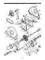
1
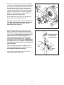
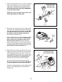
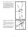
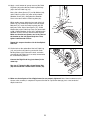
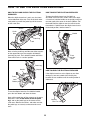
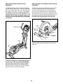
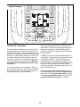
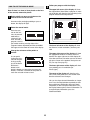
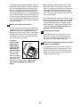
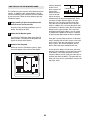
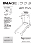
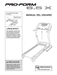
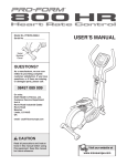
Model No. PFEVEL5986.0
Serial No.
Serial
Number
Decal
QUESTIONS?
As a manufacturer, we are committed to providing complete
customer satisfaction. If you have
questions, or if there are missing
or damaged parts, please call:
08457 089 009
Or write:
ICON Health & Fitness, Ltd.
Customer Service Department
Unit 4
Revie Road Industrial Estate
Revie Road
Beeston
Leeds, LS118JG
UK
email: [email protected]
CAUTION
Read all precautions and instructions in this manual before using
this equipment. Keep this manual for future reference.
USER’S MANUAL
TABLE OF CONTENTS
IMPORTANT PRECAUTIONS . . . . . . . . . . . . . . . . . . . . . . . . . . . . . . . . . . . . . . . . . . . . . . . . . . . . . . . . . . . . . . . .3
BEFORE YOU BEGIN . . . . . . . . . . . . . . . . . . . . . . . . . . . . . . . . . . . . . . . . . . . . . . . . . . . . . . . . . . . . . . . . . . . . . .4
ASSEMBLY . . . . . . . . . . . . . . . . . . . . . . . . . . . . . . . . . . . . . . . . . . . . . . . . . . . . . . . . . . . . . . . . . . . . . . . . . . . . . . .5
HOW TO USE THE ELLIPTICAL EXERCISER . . . . . . . . . . . . . . . . . . . . . . . . . . . . . . . . . . . . . . . . . . . . . . . . . .12
MAINTENANCE AND TROUBLESHOOTING . . . . . . . . . . . . . . . . . . . . . . . . . . . . . . . . . . . . . . . . . . . . . . . . . . .23
CONDITIONING GUIDELINES . . . . . . . . . . . . . . . . . . . . . . . . . . . . . . . . . . . . . . . . . . . . . . . . . . . . . . . . . . . . . . .24
PART LIST . . . . . . . . . . . . . . . . . . . . . . . . . . . . . . . . . . . . . . . . . . . . . . . . . . . . . . . . . . . . . . . . . . . . . . . . . . . . . .28
EXPLODED DRAWING . . . . . . . . . . . . . . . . . . . . . . . . . . . . . . . . . . . . . . . . . . . . . . . . . . . . . . . . . . . . . . . . . . . .30
ORDERING REPLACEMENT PARTS . . . . . . . . . . . . . . . . . . . . . . . . . . . . . . . . . . . . . . . . . . . . . . . . . .Back Cover
PROFORM is a registered trademark of ICON IP, Inc.
2
IMPORTANT PRECAUTIONS
WARNING:
To reduce the risk of serious injury, read the following important precautions before using the elliptical exerciser.
1. Read all instructions in this manual and all
warnings on the elliptical exerciser before
using the elliptical exerciser. Use the elliptical exercise only as described in this
manual.
10. The pulse sensor is not a medical device.
Various factors may affect the accuracy of
heart rate readings. The pulse sensor is
intended only as an exercise aid in determining heart rate trends in general.
2. It is the responsibility of the owner to ensure
that all users of the elliptical exerciser are
adequately informed of all precautions.
11. Keep your back straight while using the elliptical exerciser; do not arch your back.
12. If you feel pain or dizziness while exercising,
stop immediately and cool down.
3. The elliptical exerciser is intended for
home use only. Do not use the elliptical
exerciser in a commercial, rental, or institutional setting.
13. When you stop exercising, allow the pedals
to slowly come to a stop.
4. Keep the elliptical exerciser indoors, away
from moisture and dust. Place the elliptical
exerciser on a level surface, with a mat
beneath it to protect the floor or carpet.
Make sure that there is enough clearance
around the elliptical exerciser to mount, dismount, and use it.
14. The decal shown below has been placed on
the elliptical exerciser. If the decal is missing or illegible, call the telephone number on
the front cover of this manual and order a
free replacement decal. Apply the decal in
the location shown.
5. Inspect and properly tighten all parts regularly. Replace any worn parts immediately.
6. Keep children under age 12 and pets away
from the elliptical exerciser at all times.
7. The elliptical exerciser should not be used
by persons weighing more than 113 kg (250
lbs).
8. Wear appropriate exercise clothes while
using the elliptical exerciser. Always wear
athletic shoes for foot protection while exercising.
9. Hold the handgrip pulse sensor or the handlebars when mounting, dismounting, or
using the elliptical exerciser.
WARNING:
Before beginning this or any exercise program, consult your physician.
This is especially important for persons over the age of 35 or persons with pre-existing health problems. Read all instructions before using. ICON assumes no responsibility for personal injury or
property damage sustained by or through the use of this product.
3
BEFORE YOU BEGIN
Thank you for selecting the revolutionary PROFORM®
790 HR elliptical exerciser. The 790 HR elliptical exerciser provides a wide array of features, including two
motivational fitness games, designed to make your
workouts at home more effective and enjoyable—and
when you’re not exercising, the unique 790 HR
elliptical exerciser can be folded out of the way.
tions after reading this manual, please see the front
cover of this manual. To help us assist you, note the
product model number and serial number before contacting us. The model number is PFEVEL5986.0. The
serial number can be found on a decal attached to the
elliptical exerciser (see the front cover of this manual
for the location of the decal).
For your benefit, read this manual carefully before
you use the elliptical exerciser. If you have ques-
Before reading further, please familiarize yourself with
the parts that are labeled in the drawing below.
Handle
Fan
Game Controller
Handgrip Pulse Sensor
Console
Handlebar
Storage Magnet
Water Bottle Holder*
FRONT
Adjustment Knob
Adjustment Bracket
Wheel
Crank Arm
Pedal
Pedal Arm Latch
Handle
Storage Latch
BACK
RIGHT SIDE
Leveling Foot
*No water bottle is included
4
ASSEMBLY
Assembly requires two persons. Place all parts of the elliptical exerciser in a cleared area and remove the
packing materials. Do not dispose of the packing materials until assembly is completed. In addition to the
included hex keys, assembly requires a phillips screwdriver
, an adjustable
wrench
, and a rubber mallet
.
As you assemble the elliptical exerciser, use the drawings below to identify small parts. The number in parentheses
below each drawing is the key number of the part, from the PART LIST on pages 28 and 29. The number following the parentheses is the quantity needed for assembly. Note: Some small parts may have been pre-assembled. If a part is not in the parts bag, check to see if it has been pre-assembled.
M8 Split
Washer (90)–3
Star Washer
(112)–8
M4 x 32mm
Round Head
Screw (105)–6
M4 x 16mm
Round Head
Screw (101)–14
M4 x 14mm
Screw (104)–8
M8 x 15mm Button
Screw (116)–8
M8 Washer
(88)–6
Wave Washer
(111)–2
M8 x 23mm Shoulder
Screw (115)–4
M8 x 23mm Button
Screw (84)–4
M8 x 69mm Button
Bolt (80)–1
M8 x 41mm Button
Bolt (78)–4
M10 x 82mm Button
Screw (82)–2
M8 x 112mm Button Bolt (125)–2
M10 x 127mm Button Screw (83)–2
5
M8 Jamnut
(79)–7
M4 x 45mm
Screw (108)–2
Hub Screw (87)–8
1.
1
To make assembly easier, read the information
on page 5 before you begin assembling the
elliptical exerciser.
82
While another person lifts the Base (1), attach the
Front Stabilizer (6) to the Base with two M10 x 82mm
Button Screws (82).
119
118
Next, hold the Left Stabilizer Cover (118) and the Right
Stabilizer Cover (119) around the Base (1). Attach the
Stabilizer Covers with six M4 x 16mm Round Head
Screws (101) (only three screws are shown).
2. Remove the indicated screw and the shipping bracket
from the rear of the Base (1). Discard the screw and
the shipping bracket.
6
101
1
2
Next, turn the Base Foot (26) into the Base (1) as far
as possible.
1
Shipping
Bracket
26
Screw
3. Attach the Rear Stabilizer (7) to the Frame (2) with two
M10 x 127mm Button Screws (83).
3
83
Next, hold the handle on the Frame (2), press the
Latch Button (68), and lower the Frame until the Rear
Stabilizer (7) rests on the floor.
7
Handle
2
68
6
4. Identify the Left Crank Arm (36), which is marked with
a “Left” sticker. Hold the Left Crank Arm against the left
Crank Hub (38), and align the holes in the Left Crank
Arm with the unused holes in the Crank Hub. Next,
insert four Hub Screws (87) into the Left Crank Arm,
and finger tighten the Hub Screws into the Crank Hub.
Tighten one of the Hub Screws, and then tighten the
Hub Screw furthest from the first Hub Screw. Then,
tighten the remaining two Hub Screws.
4
98
123
38
75
87
116
Attach a Hub Cover (75) to the Left Crank Arm (36)
with four M8 x 15mm Button Screws (116).
Repeat this step on the other side of the elliptical exerciser. Make sure that the Crank Arms (36, 123) are
oriented as shown. Note: there are no Pulley
Screws (98) on the right side.
5. While another person holds the Upright (3) near the
Base (1), connect the two connectors on the Upper
Wire Harness (48) to the two connectors on the Lower
Wire Harness (49). Gently pull the upper end of the
Upper Wire Harness to remove any slack, and
insert the Upright into the Base. Attach the Upright
with an M8 x 69mm Button Bolt (80), an M8 Split
Washer (90), and an M8 Jamnut (79). Avoid pinching
the wire harnesses. Do not tighten the Button Bolt
yet; make sure that the Jamnut is in the hexagonal
hole in the Base.
Next, finger tighten two M8 x 23mm Button Screws
(84) and two M8 Split Washers (90) into the Base (1).
Do not tighten the Button Screws yet.
Attach the Water Bottle Holder (22) to the Base (1)
with two M4 x 14mm Screws (104).
87
36
116 Cutout
5
3
Avoid pinching the
wire harnesses
during this step
48
80
49
90
79
84
104
84
1
7
90
Hexagonal
Hole
90
22
6. Orient the Left Upright Cover (17) as shown, and hold it
against the Upright (3). Insert the Left Extension Wire
(135), which is marked with a tag, through the Left
Upright Cover. Attach the Left Upright Cover with two
M4 x 16mm Round Head Screws (101). Avoid pinching the Left Extension Wire.
6
Avoid pinching the
extension wires
during this step
101
3
Repeat this step for the Right Upright Cover (130)
and the Right Extension Wire (136).
17
130
135
136
101
7. The Console (5) requires four 1.5V “D” batteries; alkaline batteries are recommended. Remove the battery
cover and insert four batteries into the Console. Make
sure that the batteries are oriented as shown by
the diagrams inside the battery compartment.
Then, reattach the battery cover.
7
Battery
Cover
Note: The Console (5) can be operated with an optional power supply instead of batteries. To purchase a
power supply, call the telephone number on the
front cover of this manual. Plug one end of the
power supply into the jack at the front of the elliptical
exerciser. Plug the other end of the power supply into
an appropriate outlet that is properly installed in accordance with all local codes and ordinances.
8. While another person holds the Console (5) near the
Upright (3), connect the wire harness on the Console
to the Upper Wire Harness (48). Then, connect the
Left and Right Extenstion Wires (135, 136), which are
marked with tags, to the left and right controller wires
on the Console, which are also marked with tags.
Insert the excess wire harness into the Upright.
Attach the Console (5) to the Upright (3) with four
M4 x 16mm Round Head Screws (101). Avoid pinching the wire harnesses and the extension wires.
Attach the Transport Handle (4) to the Upright (3) with
two M8 x 112mm Button Bolts (125) and two M8
Jamnuts (79).
8
5
Batteries
8
Avoid pinching the
wires during this step
4
79
Controller
Wires
135
136
125
101
48
101
3
Wire
Harness
5
9. Identify the Left Handlebar (8) and the Left Upper Body
Arm (11), which are marked with “Left” stickers.
9
Orient the Left Handlebar (8) and the Left Upper Body
Arm (11) as shown. Insert the Left Handlebar into the
Left Upper Body Arm. Attach the Left Handlebar with
two M8 x 41mm Button Bolts (78) and two M8
Jamnuts (79). Make sure that the Jamnuts are in
the hexagonal holes in the Left Upper Body Arm.
9
8
Attach the Right Handlebar (9) to the Right Upper
Body Arm (12) in the same way.
79
79
Hexagonal
Holes
78
78
12
11
10. Apply a generous amount of the included grease to the
Pivot Axle (74). Then, apply grease to two Wave
Washers (111).
Insert the Pivot Axle (74) into the Upright (3) and center
it. Orient the Left Upper Body Arm (11) as shown, and
slide it onto the left end of the Pivot Axle. Slide the
Right Upper Body Arm (12) onto the right end of the
Pivot Axle.
Tighten an M8 x 23mm Button Screw (84) with an M8
Washer (88) and a Wave Washer (111) into each end
of the Pivot Axle (74). Make sure that the Wave
Washers are on the ends of the Pivot Axle.
9
10
3
88 84
111
Grease
Grease 74
88
11
84
111
12
11. Route the Left Extension Wire (135) through the Left
Rear Handlebar Cover (19), and then connect the Left
Extension Wire to the Left Controller Wire (127). Then,
route the Right Extension Wire (136) through the Right
Rear Handlebar Cover (21), and connect it to the
Right Controller Wire (128).
11
21
127
128
136
19
135
12. Note: For clarity, the wires that you connected in
step 11 are not shown in the drawing at the right.
12
Hold the Left Front Handlebar Cover (18) and the Left
Rear Handlebar Cover (19) around the Left Upper
Body Arm (11). Attach the Handlebar Covers with three
M4 x 32mm Round Head Screws (105). Avoid pinching the wires (not shown).
20
105
21
12
18
Attach the Right Front Handlebar Cover (20) and
the Right Rear Handlebar Cover (21) around the
Right Upper Body Arm (12) in the same way.
13. Identify the Left Pedal (13) and the Left Pedal Leg
(14), which are marked with “Left” stickers.
11
19
13
13
Attach the Left Pedal (13) to the Left Pedal Leg (14)
with an M4 x 45mm Screw (108), three M4 x 14mm
Screws (104), and four Star Washers (112).
Attach the Right Pedal (not shown) to the Right
Pedal Leg (not shown) in the same way.
112
104
112
112
10
14
108
112
104
14. Apply a small amount of grease to one of the Pedal
Leg Axles (32) and to the two Pedal Leg Bushings
(33) in the Left Pedal Leg (14).
14
Next, slide a 5mm Spacer (77), an M8 Washer (88),
and a Pedal Leg Cover (31) onto an M8 x 23mm
Shoulder Screw (115), and tighten the Shoulder
Screw a few turns into the Pedal Leg Axle (32).
11
77 31 88
77
While another person holds the front end of the Left
Pedal Leg (14) inside the bracket on the Left Upper
Body Arm (11), insert the Pedal Leg Axle (32) into
both parts. Next, slide a 5mm Spacer (77), an M8
Washer (88), and a Pedal Leg Cover (31) onto another M8 x 23mm Shoulder Screw (115), and tighten the
Shoulder Screw a few turns into the Pedal Leg Axle.
Make sure that the two Spacers are in the sides of
the bracket on the Left Upper Body Arm. Then,
tighten both Shoulder Screws.
115
31
88
115
33–Grease
Grease
32
Repeat this step on the other side of the elliptical
exerciser.
15. Lift the latch on the underside of the Left Pedal Leg
(14), and set the Left Pedal Leg on the left Crank
Bushing Sleeve (43). Release the latch, and make
sure that the Left Pedal Leg is securely connected to
the Crank Bushing Sleeve.
14
15
14
Connect the Right Pedal Leg (not shown) in the
same way.
Latch
See step 5. Tighten the M8 x 69mm Button Bolt
(80) and the two M8 x 23mm Button Screws (84).
43
16. Make sure that all parts of the elliptical exerciser are properly tightened. Note: Some hardware may be
left over after assembly is completed. To protect the floor or carpet from damage, place a mat under the
elliptical exerciser.
11
HOW TO USE THE ELLIPTICAL EXERCISER
HOW TO FOLD AND UNFOLD THE ELLIPTICAL
EXERCISER
When the elliptical exerciser is not in use, the frame
can be folded out of the way. First, lift the latch under
each pedal leg, and lift the pedal legs off the sleeves
on the crank arms.
HOW TO MOVE THE ELLIPTICAL EXERCISER
To move the elliptical exerciser, first fold it as
described at the left. Next, stand in front of the elliptical exerciser, hold the handle on the upright, and place
one foot against the center of the front stabilizer. Pull
the handle until the elliptical exerciser will roll on the
front wheels. Carefully move the elliptical exerciser to
the desired position, and then lower it.
Sleeve
Crank
Arm
Handle
Pedal Leg
Latch
Next, raise the pedal legs until they touch the magnets
on the upper body arms; the magnets will hold the
pedal legs in place. Then, hold the handle and lift the
frame until it locks in a vertical position.
Place
your foot
here
Pedal Leg
Handle
Magnet
Frame
Latch
Button
HOW TO LEVEL THE ELLIPTICAL EXERCISER
If the elliptical exerciser rocks slightly on your floor
during use, turn one or both of the leveling feet
beneath the rear stabilizer until the rocking motion is
eliminated.
To use the elliptical exerciser, first hold the handle,
press the latch button, and lower the frame.
Next, pull the pedal legs off the magnets on the upper
body arms. Then, lift the latches under the pedal
legs, and set the pedal legs on the sleeves on the
crank arms. Release the latches, and make sure that
the pedal legs are securely connected to the crank
arms.
Leveling
Feet
12
HOW TO EXERCISE ON THE ELLIPTICAL
EXERCISER
HOW TO ADJUST THE STRIDE OF THE ELLIPTICAL
EXERCISER
To mount the elliptical exerciser, hold the handlebars
and step onto the pedal that is in the lowest position.
Next, step onto the other pedal. Push the pedals until
they begin to move with a continuous motion. Note:
The pedal discs can turn in either direction. It is
recommended that you turn the pedal discs in the
direction shown by the arrow below; however, for
variety, you can turn the pedal discs in the opposite direction.
To adjust the stride of the elliptical exerciser, first pull
one of the adjustment knobs until the adjustment
bracket can be pivoted freely. Pivot the adjustment
bracket until the adjustment knob is aligned with one
of the three holes in the crank arm, and gently release
the knob. Then, pivot the adjustment bracket back and
forth slightly to make sure that the adjustment pin is
engaged in one of the three holes in the crank arm.
Crank
Arm
Handlebars
Adjustment
Bracket
Holes
Adjustment
Knob
Adjustment
Pin
Pedals
Adjust the other side of the elliptical exerciser in the
same way.
Crank
Arm
To dismount the elliptical exerciser, wait until the pedals come to a complete stop. Note: The elliptical
exerciser does not have a free wheel; the pedals
will continue to move until the flywheel stops.
When the pedals are stationary, step off the highest
pedal first. Then, step off the lower pedal.
13
CONSOLE DIAGRAM
FEATURES OF THE CONSOLE
The revolutionary console offers an array of features
designed to make your workouts more effective and
enjoyable. When you use the manual mode of the console, you can change the resistance of the pedals with
the touch of a button. While you exercise, the console
will display continuous exercise feedback. You can
also measure your heart rate using the handgrip pulse
sensor or the optional chest pulse sensor. Note: For
information about the optional chest pulse sensor,
see page 23.
The console features ten smart programs. Each program automatically changes the resistance of the pedals and prompts you to vary your pedaling pace as it
guides you through an effective workout.
The console also offers two heart rate programs that
automatically control the resistance of the pedals and
prompt you to maintain a constant pedaling pace to
keep your heart rate near target heart rate settings during your workouts.
In addition, the console features two motivational interactive games. Using the dual game controllers, play the
challenging Fat Blocker™ game or the fast-paced
Calorie Destroyer™ game during your workouts—the
harder you exercise, the greater the advantage you will
have! The console keeps track of the four highest
scores for each game—compete with other users or try
to top your own high score.
To use the manual mode of the console, follow the
steps beginning on page 15. To use a smart program,
see page 17. To use a heart rate program, see page
18. To play the Fat Blocker game, see page 20. To
play the Calorie Destroyer game, see page 22.
14
4
HOW TO USE THE MANUAL MODE
The upper left corner of the display will show
the elapsed time. Note: When a program is selected, the display will show the time remaining in the
program instead of the elapsed time.
Note: If there is a sheet of clear plastic on the face
of the console, remove the plastic.
1
Follow your progress with the display.
Begin pedaling or press any button on the
console to turn on the console.
A moment after you begin pedaling or press a
button, the display will light.
2
Select the manual mode.
Each time you
turn on the console, the manual
mode will be
selected. If you
have selected a
program, reselect
the manual mode by pressing either of the
Programs buttons repeatedly until the word MANUAL appears in the lower left corner of the display.
3
The lower left corner of the display will show
the distance, in total revolutions, you have pedaled.
Change the resistance of the pedals as
desired.
The upper right corner of the display will show
the approximate number of calories you have
burned. The upper right corner of the display will
also show your heart rate when you use the handgrip pulse sensor or the optional chest pulse sensor (see step 5 on page 16).
As you pedal,
change the resistance of the pedals by pressing
any of the Quick
Resistance
buttons numbered 1 through 12. Note: After you press the
buttons, it will take a moment for the pedals to
reach the selected resistance level.
The lower right corner of the display will show
your pedaling pace in revolutions per
minute (rpm).
The center of the display will show the resistance level of the pedals for a few seconds each
time the resistance level changes.
You can also view selected information at a larger
size. Press the Display button repeatedly to view
time and distance information, time and calorie
information, or time and pace information. Press
the Display button again to view all information. To
reset the display information, press the
Start/Reset button.
15
The console has three backlight options. The “On”
option keeps the backlight on while the console is
on. To conserve the batteries, the “Auto” option
keeps the backlight on only while you are pedaling. The “Off” option turns the backlight off. To
select a backlight option, first press and hold down
the Certified Personal Trainer Programs button for
several seconds. Next, press the increase button
to select the desired backlight option. Then, press
the Certified Personal Trainer Programs button to
save your selection.
5
When your pulse is detected, one, two, or three
dashes will appear in the display, and then your
heart rate will appear. For the most accurate heart
rate reading, hold the contacts for at least 15 seconds. Note: If you continue to hold the handgrip
pulse sensor, the display will show your heart rate
for up to 30 seconds.
If the display does not show your heart rate, make
sure that your hands are positioned as described.
Be careful not to move your hands excessively or
squeeze the metal contacts too tightly. For optimal performance, clean the metal contacts using
a soft cloth; never use alcohol, abrasives, or
chemicals to clean the contacts.
Measure your heart rate if desired.
You can measure you heart rate using either the
handgrip pulse sensor or the optional chest pulse
sensor (see page 23 for information about the
optional chest pulse sensor). Note: If you hold the
handgrip pulse sensor and wear the chest pulse
sensor at the same time, the console will not display your heart rate accurately.
6
Turn on the fan if desired.
To turn on the fan at low speed, press the Fan
button once. To turn on the fan at high speed,
press the Fan button a second time. To turn off
the fan, press the Fan button a third time.
If there are
sheets of clear
Contacts
plastic on the
metal contacts
on the handgrip
pulse sensor,
remove the plastic. To measure
your heart rate,
hold the handgrip
pulse sensor with
your palms resting against the metal contacts. Avoid moving
your hands or gripping the contacts too
tightly.
7
When you are finished exercising, the console
will turn off automatically.
If the pedals do not move for several seconds, a
tone will sound and the console will pause. If the
pedals do not move for several minutes and the
buttons are not pressed, the console will turn off
and the display will be reset.
16
As you exercise,
you will be
prompted to keep
your pedaling
pace near the target rpm setting for
the current segment. When an upward arrow appears in the display, increase your pace. When a downward
arrow appears in the display, decrease your pace.
When no arrow appears, maintain your current
pace.
HOW TO USE A SMART PROGRAM
1
Begin pedaling or press any button on the
console to turn on the console.
A moment after you begin pedaling or press a
button, the display will light.
2
Select a smart program.
To select one of
Profile
the ten smart
programs, press
the Certified
Personal Trainer
Programs button
repeatedly until
the name of the
desired program appears in the display. The program time and a profile of the resistance levels for
the program will also appear in the display.
3
Important: The target rpm settings are intended only to provide motivation. Your actual
pace may be slower than the target rpm settings. Make sure to pedal at a pace that is
comfortable for you.
If the resistance level for the current segment is
too high or too low, you can manually override the
setting by pressing the Quick Resistance buttons.
Important: When the current segment of the
program ends, the pedals will automatically
adjust to the resistance level for the next segment.
Begin pedaling to start the program.
Each program is divided into 20, 30, or 45 oneminute segments. One resistance level and one
target rpm (pace) setting are programmed for
each segment. Note: The same resistance and/or
target rpm setting may be programmed for two or
more consecutive segments.
The program will continue in this way until the last
segment ends. To stop the program at any time,
stop pedaling. A tone will sound and the time will
begin to flash in the display. To restart the program, simply resume pedaling. To reset the program, press the Start/Reset button.
The program profile will show your progress (see
the drawing above). The flashing segment of the
profile represents the current segment of the program. The height of the flashing segment indicates the resistance level for the current segment.
4
Follow your progress with the display.
See step 4 on page 15.
When the first segment of the program ends, the
resistance level and the target rpm for the second
segment will appear in the center of the display
for a few seconds to alert you. The next segment
of the profile will begin to flash, and the pedals
will automatically adjust to the resistance level for
the next segment.
5
Measure your heart rate if desired.
See step 5 on page 16.
6
Turn on the fan if desired.
See step 6 on page 16.
7
When you are finished exercising, the console
will turn off automatically.
See step 7 on page 16.
17
4
HOW TO USE A HEART RATE PROGRAM
1
To use a heart rate program, you must hold the
handgrip pulse sensor or wear the optional chest
pulse sensor (see page 23 for information about
the optional chest pulse sensor). Note: If you hold
the handgrip pulse sensor and wear the chest
pulse sensor at the same time, the console will not
display your heart rate accurately.
Begin pedaling or press any button on the
console to turn on the console.
A moment after you turn on the console, the display will light.
2
Select a heart rate program.
If you use the handgrip pulse sensor, it is not necessary to hold the handgrip pulse sensor continuously during a heart rate program; however, you
should hold the handgrip pulse sensor frequently
for the program to operate properly. Each time
you hold the handgrip pulse sensor, keep
your hands on the metal contacts for at least
30 seconds.
To select one of the two heart rate programs,
press the Heart Rate Control Programs button
repeatedly until the words HEART RATE 1 or
HEART RATE 2 appear in the display. The program time and a profile of the target heart rate
settings for the program will also appear in the
display.
3
Hold the handgrip pulse sensor or wear the
optional chest pulse sensor.
Enter a target heart rate setting.
5
When you select a
heart rate program, the maximum target heart
rate setting will
flash in the center
of the display. If
desired, use the
increase and decrease buttons to change the
maximum target heart rate setting, and then press
the Enter button. Note: If you change the maximum target heart rate setting, the intensity level
of the entire program will change.
Begin pedaling to start the program.
Each heart rate program is divided into either 20 or
30 one-minute segments. One target heart rate
setting is programmed for each segment. Note:
The same target heart rate setting may be programmed for two or more consecutive segments.
The target heart rate setting for the first segment
will be indicated by the height of the flashing segment of the profile in the display. When the first
segment of the program ends, the next segment
of the profile will begin to flash. The target heart
rate setting for the next segment will then be indicated by the height of the flashing segment of the
profile.
18
As you pedal, the console will regularly compare
your heart rate to the target heart rate setting. If
your heart rate is too far below or above the target
heart rate setting, the resistance of the pedals will
automatically increase or decrease to bring your
heart rate closer to the target heart rate setting.
The program will continue in this way until the last
segment ends. To stop the program at any time,
stop pedaling. A tone will sound and the time will
begin to flash in the display. To restart the program, simply resume pedaling. To reset the program, press the Start/Reset button.
You will also be
prompted to pedal
at a steady pace.
When an upward
arrow appears in
the display,
increase your
pace. When a downward arrow appears in the
display, decrease your pace. When no arrow
appears in the display, maintain your current
pace. Important: Make sure to pedal at a pace
that is comfortable for you.
6
Follow your progress with the display.
See step 4 on page 15.
7
Measure your heart rate if desired.
See step 5 on page 16.
8
Turn on the fan if desired.
See step 6 on page 16.
9
If the resistance level for the current segment is
too high or too low, you can manually override the
setting by pressing the Quick Resistance buttons;
however, you might not maintain the target heart
rate. Also, when the console compares your heart
rate to the target heart rate setting, the resistance
of the pedals may automatically increase or
decrease to bring your heart rate closer to the target heart rate setting.
When you are finished exercising, the console
will turn off automatically.
See step 7 on page 16.
19
A block composed
of four or five
Complete Row
black squares will
slowly move
downward until it
reaches the bottom of the arena.
Another block will then move downward. There
are blocks of eight different shapes. As each
block falls, you can move it to the left or right
using the left and right buttons on the left controller. In addition, you can rotate the block counterclockwise or clockwise using the left and right
buttons on the right controller. Once you have
positioned and oriented a block, you can speed
its motion to the bottom of the arena, if desired,
by pressing the down button on either controller.
HOW TO PLAY THE FAT BLOCKER GAME
The Fat Blocker game requires quick thinking and fast
reflexes. In addition to the console buttons, you will
use the four-button game controllers on the handlebar
to play the game. Follow the steps below to play the
Fat Blocker game.
1
Begin pedaling or press any button on the
console to turn on the console.
A moment after you begin pedaling or press a
button, the display will light.
2
Select the Fat Blocker game.
To select the Fat Blocker game, press the Fat
Blocker button. The words FAT BLOCKER will
appear at the top of the display.
3
Your goal is to maneuver the blocks so that they
form a complete row of black squares across the
entire arena. Each time you complete a row of
black squares, the row will disappear, and all
blocks above will move downward one row.
Pedal to start the game.
When you start the Fat Blocker game, a game
arena will appear in the center of the display.
As you play, the blocks will fall faster and faster;
however, your pedaling pace will affect the speed
of the blocks—the faster you pedal, the more
slowly the blocks will fall, giving you extra time to
position and orient the blocks. The game will continue until any part of a stacked block reaches the
top of the arena.
20
When the game ends, the display will show your
final score and the level of play that you reached.
The display will then show the four highest scores
recorded since the scores were reset. If desired,
press and hold down the right button on either
controller to reset the scores. Note: If your score
is one of the four highest, the display will prompt
you to enter a name consisting of three letters or
digits. While the line below the first letter is flashing, press the up and down buttons on either controller to select the desired letter or digit. Next,
press the right button on either controller and
select another letter or digit. Repeat this process
to select a third letter or digit. Then, press the
right button on either controller again. The display
will then show the four highest scores recorded
since the scores were reset.
4
Follow your progress with the display.
While you exercise and play the Fat Blocker
game, the corners of the display will show the
elapsed time, the approximate number of calories
you have burned, and your pedaling pace. In addition, the display will show your current score and
the game level that you have reached.
To pause the game, press the Display button. To
resume the game, press the Display button
repeatedly until the words FAT BLOCKER appear
at the top of the display, and then begin pedaling.
To reset the game, press the Start/Reset button.
5
When you are finished exercising, the console
will turn off automatically.
See step 7 on page 16.
21
Between the drones and the laser blaster are five
shields. You can hide the laser blaster below a
shield if desired. However, each time a shield is
hit by a laser, a piece will be vaporized.
HOW TO PLAY THE CALORIE DESTROYER GAME
The Calorie Destroyer game is a fast-paced game that
pits you against a squadron of laser-firing drones. In
addition to the console buttons, you will use the fourbutton game controllers on the handlebar to play the
game. Follow the steps below to play the Calorie
Destroyer game.
1
Your goal is to keep the laser blaster from being
hit and to keep any drone from reaching the bottom of the arena. If the laser blaster is hit, it will
be disabled and another laser blaster will appear
in its place; there are a total of four laser blasters.
If you vaporize the entire squadron of drones, a
new squadron will appear.
Begin pedaling or press any button on the
console to turn on the console.
As you play, the drones will move faster and
faster. The game will continue until all four laser
blasters are disabled or a drone reaches the bottom of the arena.
A moment after you begin pedaling or press a
button, the display will light.
2
Select the Calorie Destroyer game.
When the game ends, the display will show the
level of play that you reached and your final
score. The display will then show the four highest
scores recorded since the scores were reset. If
desired, press and hold down the right button on
either controller to reset the scores. Note: If your
score is one of the four highest, the display will
prompt you to enter a name consisting of three
letters or digits. While the line below the first letter
is flashing, press the up and down buttons on
either controller to select the desired letter or
digit. Next, press the right button on either controller and select another letter or digit. Repeat
this process to select a third letter or digit. Then,
press the right button on either controller again.
The display will then show the four highest scores
recorded since the scores were reset.
To select the Calorie Destroyer game, press the
Calorie Destroyer button. The word DESTROYER
will appear at the top of the display.
3
Pedal to start the game.
When you start the Calorie Destroyer game, a
game arena will appear in the display. Three rows
of drones will begin to move across the top of the
arena, periodically firing their lasers downward.
Each time the drones reach the left or right side
of the arena, they will reverse direction and move
downward.
4
Follow your progress with the display.
While you exercise and play the Calorie Destroyer
game, the upper left corner of the display will
show the elapsed time. In addition, the display will
show the game level that you have reached and
your current score.
To pause the game, press the Display button. To
resume the game, press the Display button
repeatedly until the word DESTROYER appears at
the top of the display, and then begin pedaling. To
reset the game, press the Start/Reset button.
At the bottom of the arena is a laser blaster. You
can fire the laser blaster at the drones by pressing the up button on either controller. In addition,
while you are pedaling, you can move the laser
blaster to the left or right using the left and right
buttons on either controller. The faster you pedal,
the faster the laser blaster will move.
5
When you are finished exercising, the console
will turn off automatically.
See step 7 on page 16.
22
THE OPTIONAL CHEST PULSE SENSOR
The optional chest pulse sensor provides hands-free
operation and continuously monitors your heart rate
during your workouts. To purchase the optional
chest pulse sensor, call the telephone number on
the front cover of this manual.
MAINTENANCE AND TROUBLESHOOTING
Inspect and tighten all parts of the elliptical exerciser
regularly. Replace any worn parts immediately.
HOW TO LEVEL THE ELLIPTICAL EXERCISER
If the elliptical exerciser rocks slightly on your floor
during use, see HOW TO LEVEL THE ELLIPTICAL
EXERCISER on page 12.
To clean the elliptical exerciser, use a damp cloth and
a small amount of mild soap. Important: To avoid
damage to the console, keep liquids away from
the console and keep the console out of direct
sunlight.
HANDGRIP PULSE SENSOR TROUBLESHOOTING
BATTERY REPLACEMENT
• Avoid moving your hands while using the handgrip
pulse sensor. Excessive movement may interfere
with heart rate readings.
If the console display becomes dim, the batteries
should be replaced; most console problems are the
result of low batteries. See assembly step 7 on page
8 for replacement instructions.
• Do not hold the metal contacts too tightly; doing so
may interfere with heart rate readings.
• For the most accurate heart rate reading, hold the
metal contacts for about 30 seconds.
HOW TO ELIMINATE FLEXING IN THE CENTER OF
THE ELLIPTICAL EXERCISER
• For optimal performance of the handgrip pulse sensor, keep the metal contacts clean. The contacts
can be cleaned with a soft cloth—never use alcohol, abrasives, or chemicals.
If the elliptical exerciser flexes in the
center during use,
turn the base foot
until the flexing is
eliminated.
Base
Foot
23
CONDITIONING GUIDELINES
During the first few minutes of exercise, your body
uses easily accessible carbohydrate calories for energy. Only after the first few minutes of exercise does
your body begin to use stored fat calories for energy.
If your goal is to burn fat, adjust the intensity of your
exercise until your heart rate is near the lowest number in your training zone as you exercise.
WARNING:
Before beginning this or any exercise program, consult your physician. This is especially important for persons over the age of 35
or persons with pre-existing health problems.
The pulse sensor is not a medical device.
Various factors may affect the accuracy of
heart rate readings. The pulse sensor is
intended only as an exercise aid in determining heart rate trends in general.
For maximum fat burning, adjust the intensity of your
exercise until your heart rate is near the middle number in your training zone as you exercise.
Aerobic Exercise
If your goal is to strengthen your cardiovascular system, your exercise must be “aerobic.” Aerobic exercise is activity that requires large amounts of oxygen
for prolonged periods of time. This increases the
demand on the heart to pump blood to the muscles,
and on the lungs to oxygenate the blood. For aerobic
exercise, adjust the intensity of your exercise until
your heart rate is near the highest number in your
training zone as you exercise.
The following guidelines will help you to plan your
exercise program. Remember that proper nutrition
and adequate rest are essential for successful results.
EXERCISE INTENSITY
Whether your goal is to burn fat or to strengthen your
cardiovascular system, the key to achieving the
desired results is to exercise with the proper intensity.
The proper intensity level can be found by using your
heart rate as a guide. The chart below shows recommended heart rates for fat burning, maximum fat
burning, and cardiovascular (aerobic) exercise.
WORKOUT GUIDELINES
Each workout should include the following three parts:
A warm-up, consisting of 5 to 10 minutes of stretching
and light exercise. A proper warm-up increases your
body temperature, heart rate, and circulation in preparation for exercise.
Training zone exercise, consisting of 20 to 30 minutes of exercising with your heart rate in your training
zone. Note: During the first few weeks of your exercise program, do not keep your heart rate in your
training zone for longer than 20 minutes.
A cool-down, with 5 to 10 minutes of stretching. This
will increase the flexibility of your muscles and will
help to prevent post-exercise problems.
To find the proper heart rate for you, first find your age
at the bottom of the chart (ages are rounded off to the
nearest ten years). Next, find the three numbers above
your age. The three numbers are your “training zone.”
The lower two numbers are recommended heart rates
for fat burning; the highest number is the recommended heart rate for aerobic exercise.
EXERCISE FREQUENCY
To maintain or improve your condition, complete three
workouts each week, with at least one day of rest
between workouts. After a few months of regular exercise, you may complete up to five workouts each week
if desired. The key to success is to make exercise a
regular and enjoyable part of your everyday life.
Fat Burning
To burn fat effectively, you must exercise at a relatively low intensity level for a sustained period of time.
24
SUGGESTED STRETCHES
1
The correct form for several basic stretches is shown at the right.
Move slowly as you stretch—never bounce.
1. Toe Touch Stretch
Stand with your knees bent slightly and slowly bend forward from
your hips. Allow your back and shoulders to relax as you reach
down toward your toes as far as possible. Hold for 15 counts,
then relax. Repeat 3 times. Stretches: Hamstrings, backs of
knees, and back.
2
2. Hamstring Stretch
Sit with one leg extended. Bring the sole of the opposite foot
toward you and rest it against the inner thigh of your extended
leg. Reach toward your toes as far as possible. Hold for 15
counts, then relax. Repeat 3 times for each leg. Stretches:
Hamstrings, lower back, and groin.
3
3. Calf/Achilles Stretch
With one leg in front of the other, reach forward and place your
hands against a wall. Keep your back leg straight and your back
foot flat on the floor. Bend your front leg, lean forward, and move
your hips toward the wall. Hold for 15 counts, then relax. Repeat
3 times for each leg. To cause further stretching of the achilles
tendons, bend your back leg as well. Stretches: Calves, achilles
tendons, and ankles.
4
4. Quadriceps Stretch
With one hand against a wall for balance, reach back and grasp
one foot with your other hand. Bring your heel as close to your
buttocks as possible. Hold for 15 counts, then relax. Repeat 3
times for each leg. Stretches: Quadriceps and hip muscles.
5. Inner Thigh Stretch
Sit with the soles of your feet together and your knees outward.
Pull your feet toward your groin as far as possible. Hold for 15
counts, then relax. Repeat 3 times. Stretches: Quadriceps and hip
muscles.
25
5
NOTES
26
NOTES
27
PART LIST—Model No. PFEVEL5986.0
Key No. Qty.
1
2
3
4
5
6
7
8
9
10
11
12
13
14
15
16
17
18
19
20
21
22
23
24
25
26
27
28
29
30
31
32
33
34
35
36
37
38
39
40
41
42
43
44
45
46
47
48
49
50
1
1
1
1
1
1
1
1
1
2
1
1
1
1
1
1
1
1
1
1
1
1
2
2
2
1
2
1
1
2
4
2
8
1
2
1
2
2
1
1
2
4
2
2
1
1
2
1
1
1
Description
Key No. Qty.
Base
Frame
Upright
Transport Handle
Console
Front Stabilizer
Rear Stabilizer
Left Handlebar
Right Handlebar
Game Grip
Left Upper Body Arm
Right Upper Body Arm
Left Pedal
Left Pedal Leg
Right Pedal
Right Pedal Leg
Left Upright Cover
Left Front Handlebar Cover
Left Rear Handlebar Cover
Right Front Handlebar Cover
Right Rear Handlebar Cover
Water Bottle Holder
Front Stabilizer Endcap
Rear Stabilizer Endcap
Wheel
Base Foot
Leveling Foot
Left Side Shield
Right Side Shield
Upper Body Bushing
Pedal Leg Cover
Pedal Leg Axle
Pedal Leg Bushing
Base Axle
Base Bushing
Left Crank Arm
Adjustment Arm Cover
Crank Hub
Pulley Spacer
Pulley
Adjustment Arm
Crank Bushing
Crank Bushing Sleeve
Crank Bearing Set
Crank
Crank Spacer
Crank Snap Ring
Upper Wire Harness
Lower Wire Harness
Reed Switch/Wire
51
52
53
54
55
56
57
58
59
60
61
62
63
64
65
66
67
68
69
70
71
72
73
74
75
76
77
78
79
80
81
82
83
84
85
86
87
88
89
90
91
92
93
94
95
96
97
98
99
100
28
1
1
1
1
1
1
1
1
1
1
1
2
2
1
1
2
1
1
1
1
1
1
2
1
2
2
4
4
9
1
2
2
2
8
1
2
8
8
2
3
1
1
1
4
1
1
1
4
2
2
R1106A
Description
Belt
Flywheel
“C” Magnet
Pillow Block
Magnet
Spring
Idler
Idler Bracket
Clamp
Reed Switch Bracket
Base Pin
Latch Bracket Spacer
Hair Pin
Latch Bracket
Pivot Bracket
Pivot Bracket Spacer
Frame Pin
Latch Button
Roll Pin
Motor
Resistance Cable Pulley
Resistance Cable Set
Foam Grip
Pivot Axle
Hub Cover
Adjustment Knob
5mm Spacer
M8 x 41mm Button Bolt
M8 Jamnut
M8 x 69mm Button Bolt
M10 Nylon Locknut
M10 x 82mm Button Screw
M10 x 127mm Button Screw
M8 x 23mm Button Screw
M6 x 10mm Button Screw
Crank Screw
Hub Screw
M8 Washer
M10 x 60mm Button Screw
M8 Split Washer
Flywheel Spacer
Flywheel Washer
Flywheel Snap Ring
Pillow Block Screw
Stop Screw
M8 x 35mm Screw
“E” Clip
Pulley Screw
Adjustment Pin
M4 x 25mm Screw
Key No.
101
102
103
104
105
106
107
108
109
110
111
112
113
114
115
116
117
118
119
120
Qty.
14
4
23
8
6
2
6
2
2
2
2
8
1
1
4
8
2
1
1
4
Description
Key No.
M4 x 16mm Round Head Screw
Motor Washer
M4 x 16mm Screw
M4 x 14mm Screw
M4 x 32mm Round Head Screw
Adjustment Spring
M4 x 12mm Screw
M4 x 45mm Screw
Large Snap Ring
M8 Small Washer
Wave Washer
Star Washer
M10 Washer
M6 Nut
M8 x 23mm Shoulder Screw
M8 x 15mm Button Screw
Large Wave Washer
Left Stabilizer Cover
Right Stabilizer Cover
M4 x 12mm Round Head Screw
121
122
123
124
125
126
127
128
129
130
131
132
133
134
135
136
#
#
#
Qty.
Description
2
2
1
2
2
1
1
1
1
1
1
2
2
2
1
1
2
1
1
M8 Large Washer
Middle Wave Washer
Right Crank Arm
Flywheel Bracket
M8 x 112mm Button Bolt
Power Jack/Wire
Left Controller Wire
Right Controller Wire
Power Jack Bracket
Right Upright Cover
Upright Endcap
Transport Handle Endcap
Bearing Set Spacer
Pedal Leg Latch
Left Extension Wire
Right Extension Wire
Hex Key
Grease
User’s Manual
Note: “#” indicates a non-illustrated part. Specifications are subject to change without notice. See the back cover
of this manual for information about ordering replacement parts.
29
EXPLODED DRAWING A—Model No. PFEVEL5986.0
4
120
79
105
132
131
101
127
107
88
33
125
120
10
107
132
10
R1106A
111
78
79
20
5
84
33
101
8
130
74
21
101
3
136
18
105
30
17
9
30
135
101
33
79
105
48
88
77
80
101
78
111
128
12
79
33
90
77
22
90
15
49
84
73
84
90
84
19
11
104
101
73
126
31
88
33
16
115
88
77
33
31
112 104
108
119
129
14
133
101
115
103
33
34
112
112
108
104
84
104
88
25 89
82
35
26
81
25
81
13
104
134
103
89
6
103
30
103
84
88
112
134
112
35
101
32
115
115
88
77
88
32
31
101
31
133
1
118
33
23
23
EXPLODED DRAWING B—Model No. PFEVEL5986.0
R1106A
103
103
29
94
52
54
93
92
91
103
94
124
79
110
94
107
57
124
53
55
72
56
110 79
71
103
59
51
50
103
107
102
103
60
70 102
103
58
96
85
2
61
95
62
63
103
64
38 86
114
66
97 113 66
63
62 65
69
28
44
68
45
44
98 47
46
109
98
40
107
47
67
100
103
100
39
76
42 117
42
37
38
103
43
120
41
107
106
86
121
84
99
116
75
87
87
24
122 87
36
75
121
84
116
122
123
106
120
117
87
99
27
41
42
42
76
37
7
24
43
83
27
109
31
ORDERING REPLACEMENT PARTS
To order replacement parts, contact the ICON Health & Fitness, Ltd. office, or write:
ICON Health & Fitness, Ltd.
Customer Service Department
Unit 4, Revie Road Industrial Estate
Revie Road
Beeston
Leeds, LS118JG
UK
Tel:
08457 089 009
Outside the UK: (44) 113 387 7133
Fax: (44) 113 387 7125
To help us assist you, please be prepared to give the following information:
• the MODEL NUMBER of the product (PFEVEL5986.0)
• the NAME of the product (PROFORM 790 HR elliptical exerciser)
• the SERIAL NUMBER of the product (see the front cover of this manual)
• the KEY NUMBER and DESCRIPTION of the part(s) (see pages 28 to 31)
Part No. 246427 R1106A
Printed in China © 2006 ICON IP, Inc.