1
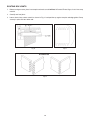
ESPAÑOL: PÁGINA 15
FRANÇAISE : PAGE 29
Instruction
manual
Dovetail Fixture/Jig
MODEL 4112 Includes 1/2" Half-Blind
MODEL 4113 Dovetail Templet
MODEL 4114
For 1/4" Half-Blind
Dovetails
MODEL 4115
For 1/2" Box Joints
To learn more about Porter-Cable
visit our website at:
http://www.porter-cable.com
IMPORTANT
Please make certain that the person who is
to use this equipment carefully reads and
understands these instructions before
starting operations.
The Model and Serial No. plate is located on the main
housing of the tool. Record these numbers in the
spaces below and retain for future reference.
Model No. _____________________________________
Type __________________________________________
Serial No.______________________________________
Copyright © 2003 Porter-Cable Corporation
Part No. 900487 - 09-12-03
SAFETY GUIDELINES - DEFINITIONS
This manual contains information that is important for you to know and understand. This information relates to protecting YOUR SAFETY and PREVENTING EQUIPMENT PROBLEMS. To help you recognize this information, we use
the symbols to the left. Please read the manual and pay attention to these sections.
Indicates an imminently hazardous situation which, if not avoided, will result in death or serious injury.
Indicates a potentially hazardous situation which, if not avoided, could result in death or serious injury.
Indicates a potentially hazardous situation which, if not avoided, may result in minor or moderate injury.
Used without the safety alert symbol indicates potentially hazardous situation which, if not avoided, may
result in property damage.
IMPORTANT SAFETY INSTRUCTIONS
Read and understand all instructions. Failure to follow all instructions listed below, may
result in electric shock, fire and/or serious personal injury.
SAVE THESE INSTRUCTIONS.
There are certain applications for which this tool was designed. Porter-Cable strongly recommends that this
tool NOT be modified and/or used for any application other than for which it was designed. If you have any questions relative to
its application DO NOT use the tool until you have written Porter-Cable and we have advised you.
Technical Service Manager
Porter-Cable Corporation
4825 Highway 45 North
Jackson, TN 38305
1. KEEP WORK AREA CLEAN. Cluttered areas and benches invite injuries.
2. AVOID DANGEROUS ENVIRONMENT. Don’t expose power tools to rain. Don’t use power tools in damp or wet
locations. Keep area well lit. Avoid chemical or corrosive environment. Do not use tool in presence of flammable
liquids or gases.
3. GUARD AGAINST ELECTRIC SHOCK. Prevent body contact with grounded surfaces. For example: pipes,
radiators, ranges, refrigerator enclosures.
4. KEEP CHILDREN AWAY. Do not let visitors contact tool or extension cord. All visitors should be kept away from
work area.
5. STORE IDLE TOOLS. When not in use, tools should be stored in dry, and high or locked-up place – out of reach
of children.
6. DON’T FORCE TOOL. It will do the job better and safer at the rate for which it was intended.
7. USE RIGHT TOOL. Don’t force small tool or attachment to do the job of a heavy duty tool. Don’t use tool for
purpose not intended – for example – do not use a circular saw for cutting tree limbs or logs.
8. DRESS PROPERLY. Do not wear loose clothing or jewelry. Loose clothing, draw strings and jewelry can be
caught in moving parts. Rubber gloves and non-skid footwear are recommended when working outdoors. Wear
protective hair covering to contain long hair.
9. USE ANSI Z87.1 SAFETY GLASSES. Wear safety glasses or goggles while operating power tools. Also face or
dust mask if operation creates dust. All persons in the area where power tools are being operated should also
wear safety glasses and face or dust mask.
10. DON’T ABUSE CORD. Never carry tool by cord or yank it to disconnect from receptacle. Keep cord from heat,
oil, and sharp edges. Have damaged or worn power cord and strain reliever replaced immediately. DO NOT
ATTEMPT TO REPAIR POWER CORD.
11. SECURE WORK. Use clamps or a vise to hold work. It’s safer than using your hand and it frees both hands to
operate tool.
12. DON’T OVERREACH. Keep proper footing and balance at all times.
13. MAINTAIN TOOLS WITH CARE. Keep tools sharp and clean for better and safer performance. Follow
instructions for lubricating and changing accessories. Inspect tool cords periodically and if damaged, have
repaired by authorized service facility. Inspect extension cords periodically and replace if damaged. Have all
worn, broken or lost parts replaced immediately. Keep handles dry, clean and free from oil and grease.
14. DISCONNECT TOOLS when not in use, before servicing, and when changing accessories such as blades, bits, cutters, etc.
15. REMOVE ADJUSTING KEYS AND WRENCHES. Form habit of checking to see that keys and adjusting
wrenches are removed from the tool before turning it on.
2
16. AVOID UNINTENTIONAL STARTING. Do not carry a plugged-in tool with finger on switch. Be sure switch is off
when plugging in. Keep hands, body and clothing clear of blades, bits, cutters, etc. when plugging in the tool.
17. OUTDOOR USE EXTENSION CORDS. When tool is used outdoors, use only extension cords marked “Suitable
for use with outdoor appliances – store indoors when not in use.” If an extension cord is to be used outdoors it
must be marked with the suffix W-A or w following the cord type designation.
18. STAY ALERT. Watch what you are doing. Use common sense. Do not operate tool when you are tired or while
under the influence of medication, alcohol or drugs.
19. CHECK DAMAGED PARTS. Before further use of the tool, a guard or other part that is damaged should be
carefully checked to determine that it will operate properly and perform its intended function. Check for alignment
of moving parts, binding of moving parts, breakage of parts, mounting, and any other conditions that may affect
its operation. A guard or other part that is damaged should be properly repaired or replaced by an authorized
service center unless otherwise indicated elsewhere in this instruction manual. Have defective switches replaced
by authorized service center. Do not use tool if switch does not turn it on and off.
20. WEAR ANSI S3.19 EAR PROTECTION to safeguard against possible hearing loss.
SAVE THESE INSTRUCTIONS
ADDITIONAL SAFETY RULES
FAILURE TO FOLLOW THESE RULES MAY RESULT IN SERIOUS PERSONAL INJURY.
1.
2.
3.
4.
5.
6.
7.
READ AND FOLLOW ALL SAFETY INSTRUCTIONS in the instruction manual supplied with your router.
SECURE WORK. Be sure Dovetail Fixture/Jig and work is anchored securely to prevent movement.
BE SURE CORD SET IS FREE and will not hang up during routing operations.
KEEP HANDS CLEAR of cutter when motor is running to prevent personal injury.
MAINTAIN FIRM GRIP on router when starting motor to resist starting torque.
STAY ALERT and keep cutter free, clear of all foreign objects while motor is running.
BE SURE MOTOR HAS COMPLETELY STOPPED before removing router from Dovetail Fixture/Jig and setting
Dovetail Fixture/Jig down between operations.
8. NEVER REMOVE ROUTER MOTOR from router base while templet guide and dovetail bit are installed. Dovetail
bit may not fit through hole in templet guide.
9. TIGHTEN TEMPLET GUIDE LOCKNUT SECURELY.
10. SOME WOOD CONTAINS PRESERVATIVES WHICH CAN BE TOXIC. Take extra care to prevent inhalation and
skin contact when working with these materials. Request, and follow, any safety information available from your
material supplier.
REPLACEMENT PARTS
When servicing use only identical replacement parts.
FOREWORD
Porter-Cable Base Model 4112 Dovetail Fixture/Jig together with a Porter-Cable router, templets, templet guides and
router bits, can be used to produce the following types of joints for drawers and boxes.
1/2
" Half-Blind Dovetails
" Half-Blind Rabbeted Dovetails
1/4" Half-Blind Dovetails
1/4" Half-Blind Rabbeted Dovetails
1/2" Box Joint
1/2
NOTICE: THE PHOTO ON THE MANUAL COVER ILLUSTRATES THE
CURRENT PRODUCTION MODEL. ALL OTHER ILLUSTRATIONS
CONTAINED IN THE MANUAL ARE REPRESENTATIVE ONLY AND MAY
NOT DEPICT THE ACTUAL COLOR, LABELING OR ACCESSORIES
AND ARE INTENDED TO ILLUSTRATE TECHNIQUE ONLY.
CAPACITY
Porter-Cable Base Model 4112 can be used with stock up to 12" wide and from 7/16" to 1" in thickness.
3
ASSEMBLY AND ADJUSTMENT
1. Clamp Knobs (4)
2. Spacers (4)
3. 10-32 x .375 Socket
Head Screws (4)
4. Templet Brackets (2)
5. Springs (4)
6. 1/4-20 Knurled Nuts (2)
7. 1/4-20 Lock Nuts (2)
8. Base
9. Top Clamp Bar (Long)
10. Front Clamp Bar (Short)
11. Templet
12. Right Edge Guide
(One #1 & One #2)
13. Left Edge Guide
(One #1 & One #2)
14. 1/4-20 x 1.5" Bolt (2)
15. 10-32 x .375 Pan Head
Screw (2)
16. 1/4 Washer (2)
17. 1/4-20 x 1.75" Bolt (4)
18. 1/4-20 Jam Nut (6)
Fig. 1
NOTE: Refer to Fig. 1 for the various parts of the Model 4112 Dovetail Fixture/Jig.
1. Insert jam nuts, item 18, into each of the outside recessed areas on front of the base, item 8. Thread bolts,
item 14, into each jam nut and tighten firmly.
2. Insert the remaining jam nuts, item 18, into the remaining recessed areas on the front and top of
base, item 8. Thread bolt, item 17, into jam nut and tighten firmly.
3. Thread locknuts, item 7, on bolts, item 14 up to the jam nuts and tighten firmly.
4. Thread on knurled nuts, item 6, on bolts, item 14 up to the locknuts and tighten firmly.
5. Select the edge guide to be used, either #1 for half-blind dovetails or #2 half-blind rabbeted dovetails. Place
right and left edge guides, items 12 and 13, on base, item 8, and assemble with screws, item 15. Slide edge
guides to end of base. Do not tighten at this time.
6. To install top clamp bar item 9, place springs item 5 on bolts, item 17, followed by the top clamp bar then
spacers, item 2. Retain assembly with clamp knobs, item 1.
6A.To install front clamp bar item 10, place washers item 16 (used on front bar only) on bolts item 17. Add springs
item 5, on bolts, item 17, followed by the front clamp bar then spacers, item 2. Retain assembly with clamp
knobs, item 1. NOTE: When clamping material thicker than ¾", the spacers, item 2, will need to be removed.
7. Attach templet, item 11, to templet brackets, item 4, with templet retaining screws, item 3.
8. Insert assembled templet between Iocknuts, item 7, and knurled nuts, item 6.
9. The completely assembled Dovetail Fixture/Jig should be securely mounted to a sturdy bench or stand to
prevent movement during routing operations. Slots are provided in the front and back of the base for this
purpose.
ADJUSTING TEMPLET LOCATION
Front to back positioning of the templets is accomplished by varying the location of the locknuts (item 7, Fig. 1).
ADJUSTING EDGE GUIDE LOCATION
1. Remove templet from Dovetail Fixture/Jig. NOTE: DO NOT UNCLAMP DRAWER FRONT.
2. Loosen edge guide retaining screw, (item 15, Fig. 1) and slide edge guide to drawer front and secure in place.
3. Replace templet.
4
IDENTIFYING DRAWER PARTS
It is recommended that scrap lumber be used when making your first dovetail cut so all adjustments and fits can be
checked to insure a satisfactory joint. Once the templet and router have been set up to rout a satisfactory dovetail
joint, any number of joints can be made.
1. Arrange the drawer front and side pieces as shown in Fig. 2.
NOTE: Ends of front and side pieces must be cut square with the length of the pieces to produce good
dovetail joints.
2. Mark the “outside”, “inside” and “ends” of each piece as shown in Fig. 2.
Right Side
of Drawer
OU
TS
IDE
LEFT END
LEFT END
INS
IDE
IDE
TS
U
O
Front of Drawer
Left Side
of Drawer
Fig. 2
5
1/2
" HALF-BLIND DOVETAILS
The following are required to produce 1/2" half-blind dovetails.
#1
Edge Guide (furnished with Model 4112)
4113 1/2" Half-Blind Dovetail Templet (furnished with Model 4112)
42046 5/8" Templet Guide (furnished with Model 4112)
Available
42237 Locknut (furnished with Model 4112)
as
Accessories
43705 Carbide Tipped, 1/2" Dovetail Bit (1/4" Shank)
or
43750 Carbide Tipped, 1/2" Dovetail Bit (1/2" Shank)
Fig. 3
PREPARING ROUTER
1.
2.
3.
4.
5.
DISCONNECT ROUTER FROM POWER SOURCE.
Insert templet guide, (A) Fig. 4, in hole (B), in router sub-base (C).
Install templet guide locknut (D) on templet guide and firmly tighten to lock templet guide in sub-base.
Insert dovetail bit, (A) Fig. 5, through templet guide into router collet.
Adjust router so dovetail bit projection (B) from bottom of router sub-base (C), is 9/16".
Fig. 4
Fig. 5
CLAMPING DRAWER PARTS
1. Temporarily clamp the left side of the drawer “inside out” under front clamp bar and extending approximately 1/4"
above top surface of the base as shown in Fig. 6.
Fig. 6
Fig. 7
6
Fig. 8
2. Place drawer front “inside up” under top clamp bar and against side of drawer which is extending above surface
of Dovetail Fixture/Jig.
3. Place the 1/2" half-blind dovetail templet on top of the drawer front. Using a standard scale or ruler, adjust locknuts,
item 7, Fig. 1, so there is 19/32" from back of templet slots to edge of drawer front at both ends of templet (see Fig.
8). Tighten knurled nuts, item 6, Fig. 1, to secure templet in place.
4. Loosen top clamp bar and position drawer front so that the left edge is 3/16" (see Fig. 8) past the left edge of the
first templet slot and clamp in place.
5. Remove 1/2" half-blind dovetail templet (DO NOT LOOSEN TOP CLAMP BAR) and locate #1 edge guide against
drawer front, secure in place and replace 1/2" half-blind dovetail templet and secure it in place.
6. Loosen front clamp bar and raise side of drawer so that it is in contact with the underside of the templet and
against the edge guide. Tighten front clamp bar securely.
ROUTING DOVETAILS
DISCONNECT ROUTER FROM POWER
SOURCE.
1. Be sure router motor is “off” and plug into power source.
2. Set router squarely on finger templet to the right of
drawer pieces.
3. Make sure bit is clear of work and will not strike
Dovetail Fixture/Jig base.
4. Start the motor and make the first cut along the entire
outside edge of the finger templet, from right to left, in
the direction of the arrow (A) Fig. 9. This will prevent
chipping of the edge of the drawer piece when the router
is moved in and out of the templet.
5. Now, carefully move the router from left to right around
the templet outline, in and out of the slots as shown by
arrow (B) Fig. 9.
6. Next, examine the drawer pieces to make sure they
have been cleanly routed. See Fig. 10.
Fig. 9
7. Remove drawer pieces and fit together, matching dovetail (A) with slot (B), Fig. 10. If joint is loose, slightly
increase depth of cut. If joint is tight, slightly decrease depth of cut. The bit is raised or lowered by adjusting
the router motor in the router base with the motor “off”.
8. After obtaining a snug dovetail, assemble parts and check the relation of the end of the drawer front to the side
of the left side of the drawer. If the drawer front overhangs side of drawer, decrease 19/32" dimension in step 3
under CLAMPING DRAWER PARTS. If side of drawer overhangs front, increase 19/32" dimension.
7
IN
SI
D
E
Drawer Front
IDE
INS
Left Side
of Drawer
Fig. 10
9. Fig. 11 shows both the left and right corner of a drawer fitted together after they were both routed from the left
end of the templet. Note the location of partial pins on drawer sides.
10. If for appearance reasons the partial pins are desired to be in the same location of both sides of the drawer as
shown in Fig. 12, then rout the right end of the drawer front and right side of the drawer on the right end of the
templet. Adjust the edge guide the same as those on the left (mirror image).
Partial Pin
Right Side
of Drawer
(Pin Board)
Left Side
of Drawer
(Pin Board)
Front of Drawer
(Tail Board)
Partial Pin
Fig. 11
Partial Pin
Right Side
of Drawer
(Pin Board)
Left Side
of Drawer
(Pin Board)
Front of Drawer
(Tail Board)
Fig. 12
8
1/4
" HALF-BLIND DOVETAILS
1
/4" Half-Blind Dovetails
The following are required to produce 1/4" half-blind dovetails:
Available
as
Accessories
889676 #3 Edge Guides (furnished with Model 4114)
42237 Locknut (furnished with Model 4112)
1
/4" Half-Blind Dovetail Templet
4114
5
42054
/16" Templet Guide
43639 High Speed Steel, 1/4" Dovetail Bit
Fig. 13
PREPARING ROUTER
Prepare router the same as for 1/2" half-blind dovetails except install 42054 templet guide, 43639 bit, and adjust depth
of cut (B) Fig. 5 to 9/16".
CLAMPING DRAWER PARTS
Drawer parts are clamped in the same manner as those for 1/2" half-blind dovetails except for the following:
1. Position the 1/4" half-blind dovetail templet so that there is 9/32" from back of templet slots to edge of drawer front
(see Fig. 14).
2. Position drawer front so the left edge is 1/8" (see Fig. 14) past the left edge of the first templet slot.
3. Locate #3 edge guide against drawer front.
ROUTING DOVETAILS
Route dovetails and check for fit the same as those for 1/2" half-blind dovetails.
Fig. 14
9
1/2
" AND 1/4" HALF-BLIND RABBETED DOVETAILS
Half-Blind Rabbeted Dovetails
The same accessories are required as those for 1/2" and 1/4" Half-Blind
Dovetails except for the edge guides.
Use #2 Edge Guide for 1/2" Rabbeted Dovetails (furnished with Model 4112)
Use #4 Edge Guide for 1/4" Rabbeted Dovetails (furnished with Model 4114)
Fig. 15
PREPARING ROUTER
PREPARING DRAWER FRONT
The drawer front should be 3/4" longer and 3/4" wider than the
drawer size required and have a 3/8" x 7/16" deep rabbet cut
completely around the inside of the drawer front.
IN
SI
D
E
Prepare router the same as that for 1/2" or 1/4" half-blind
dovetails depending on size to be cut.
NOTE: Maximum depth of drawer is 105/8", for 1/2"
rabbeted dovetails.
Fig. 16
CLAMPING DRAWER PARTS AND ROUTING DOVETAILS
Parts are clamped and routed much in the same manner as those for half-blind dovetails, except the location of the
drawer front must be adjusted to allow for the rabbet, and FRONT AND SIDES OF DRAWER MUST BE ROUTED
SEPARATELY.
1. Position drawer front “inside up” on top of Dovetail Fixture/Jig maintaining dimensions to templet shown in
Fig. 17. A gauge block with a 3/8" rabbet may be used to position drawer front as shown in Fig. 17A.
2. Locate either #2 or #4 edge guide, depending on size of dovetail to be cut, to edge of drawer front.
3. Drawer front may now be routed.
4. Remove drawer front and locate drawer side against edge guide in the same manner as that for 1/2" half-blind
dovetails.
NOTE: A backup piece should be used in place of the drawer front to prevent tear-out when routing sides of
drawer.
5. Route drawer side and check for fit the same as for 1/2" half-blind dovetails.
Fig. 17
Fig. 17A
10
1/2
" BOX JOINTS
1/2
" Box Joint
The following are required to produce 1/2" box joints:
Available
as
Accessories
889676
42046
42237
4115
43318
or
43057
#3 Edge Guides (furnished with Model 4115)
/8" Templet Guide (furnished with Model 4112)
Locknut (furnished with Model 4112)
1
/2" Box Joint Templet
1
/2" Carbide Tipped Straight Bit (1/4" Shank)
5
1
/2" Carbide Tipped Straight Bit (1/2" Shank)
Fig. 18
NOTE: Any material up to 13/16" thick can be joined together with box joints.
PREPARING ROUTER
Prepare router the same as for 1/2" half-blind dovetails except install 1/2" straight bit and adjust depth of cut, (B) Fig. 5,
equal to 1/4" plus thickness of material to be joined.
CLAMPING BOX PARTS
NOTE: All box joint cuts are made with the box parts clamped to the front of the Dovetail Fixture/Jig.
1. Install #3 edge guides to Dovetail Fixture/Jig and slide to end of base, do not tighten at this time.
2. Place a piece of scrap material, that is approximately 1/4" thicker and at least as wide as the boards to be joined,
under the top clamp and flush with front of Dovetail Fixture/Jig.
3. Place the box joint templet on top of the scrap material and adjust so there is about 3/8" (Fig. 19) from back of
templet slot to edge of scrap material at both ends of templet.
4. Mark center of board to be routed (see Fig. 20). Place board under front clamp, against bottom of box templet.
Locate the board center mark 1/16" to the right of the templet finger slot that is closest to the left end of the templet
(see Fig. 20).
5. Slide edge guide to the right against board to be routed and secure in place.
Fig. 19
11
ROUTING BOX JOINTS
1. Before turning on router, place it on templet and make sure bit will not hit Dovetail Fixture/Jig as it cuts into scrap
material.
2. Carefully rout box joints.
3. Loosen front clamp, rotate material as shown in Fig. 21 and position up against templet and edge guide. Clamp
securely in place and rout other end.
Fig. 20
Fig. 21
Assemble Box
Fig. 22
12
MAINTENANCE
KEEP TOOL CLEAN
Periodically blow out all air passages with dry compressed air. Clean all plastic parts with a soft damp cloth. NEVER
use solvents to clean plastic parts. They could possibly dissolve or otherwise damage the material.
WEAR ANSI Z87.1 SAFETY GLASSES WHILE USING COMPRESSED AIR.
SERVICE AND REPAIRS
All quality tools will eventually require servicing or replacement of parts due to wear from normal use. These operations,
including brush inspection and replacement, should ONLY be performed by either an AUTHORIZED PORTER-CABLE
SERVICE STATION or a PORTER-CABLE•DELTA FACTORY SERVICE CENTER. All repairs made by these agencies are fully
guaranteed against defective material and workmanship. We cannot guarantee repairs made or attempted by anyone other
than these agencies.
Should you have any questions about your tool, feel free to write us at any time. In any communications, please give all
information shown on the nameplate of your tool (model number, type, serial number, etc.).
ACCESSORIES
A complete line of accessories is available from your Porter-Cable•Delta Supplier, Porter-Cable•Delta Factory
Service Centers, and Porter-Cable Authorized Service Stations. Please visit our Web Site www.porter-cable.com
for a catalog or for the name of your nearest supplier.
Since accessories other than those offered by Porter-Cable•Delta have not been tested with
this product, use of such accessories could be hazardous. For safest operation, only
Porter-Cable•Delta recommended accessories should be used with this product.
13
PORTER-CABLE LIMITED
ONE YEAR WARRANTY
Porter-Cable warrants its Professional Power Tools for a period of one year from the date of original purchase. We
will repair or replace at our option, any part or parts of the product and accessories covered under this warranty
which, after examination, proves to be defective in workmanship or material during the warranty period. For repair
or replacement return the complete tool or accessory, transportation prepaid, to your nearest Porter-Cable Service
Center or Authorized Service Station. Proof of purchase may be required. This warranty does not apply to repair
or replacement required due to misuse, abuse, normal wear and tear or repairs attempted or made by other than
our Service Centers or Authorized Service Stations.
ANY IMPLIED WARRANTY, INCLUDING THE IMPLIED WARRANTIES OF MERCHANTABILITY AND FITNESS FOR
A PARTICULAR PURPOSE, WILL LAST ONLY FOR ONE (1) YEAR FROM THE DATE OF PURCHASE.
To obtain information on warranty performance please write to: PORTER-CABLE CORPORATION, 4825 Highway
45 North, Jackson, Tennessee 38305; Attention: Product Service. THE FOREGOING OBLIGATION IS PORTERCABLE’S SOLE LIABILITY UNDER THIS OR ANY IMPLIED WARRANTY AND UNDER NO CIRCUMSTANCES
SHALL PORTER-CABLE BE LIABLE FOR ANY INCIDENTAL OR CONSEQUENTIAL DAMAGES. Some states do
not allow limitations on how long an implied warranty lasts or the exclusion or limitation of incidental or
consequential damages, so the above limitation or exclusion may not apply to you.
This warranty gives you specific legal rights and you may also have other legal rights which vary from state to state.
14
PORTER-CABLE • DELTA SERVICE CENTERS
(CENTROS DE SERVICIO DE PORTER-CABLE • DELTA)
Parts and Repair Service for Porter-Cable • Delta Machinery are Available at These Locations
(Obtenga Refaccion de Partes o Servicio para su Herramienta en los Siguientes Centros de Porter-Cable • Delta)
ARIZONA
Tempe 85282 (Phoenix)
2400 West Southern Avenue
Suite 105
Phone: (602) 437-1200
Fax: (602) 437-2200
CALIFORNIA
Ontario 91761 (Los Angeles)
3949A East Guasti Road
Phone: (909) 390-5555
Fax: (909) 390-5554
San Leandro 94577 (Oakland)
3039 Teagarden Street
Phone: (510) 357-9762
Fax: (510) 357-7939
COLORADO
Arvada 80003 (Denver)
8175 Sheridan Blvd., Unit S
Phone: (303) 487-1809
Fax: (303) 487-1868
FLORIDA
Davie 33314 (Miami)
4343 South State Rd. 7 (441)
Unit #107
Phone: (954) 321-6635
Fax: (954) 321-6638
Tampa 33609
4538 W. Kennedy Boulevard
Phone: (813) 877-9585
Fax: (813) 289-7948
ILLINOIS
Addison 60101 (Chicago)
400 South Rohlwing Rd.
Phone: (630) 424-8805
Fax: (630) 424-8895
Woodridge 60517 (Chicago)
2033 West 75th Street
Phone: (630) 910-9200
Fax: (630) 910-0360
MARYLAND
Elkridge 21075 (Baltimore)
7397-102 Washington Blvd.
Phone: (410) 799-9394
Fax: (410) 799-9398
MASSACHUSETTS
Braintree 02185 (Boston)
719 Granite Street
Phone: (781) 848-9810
Fax: (781) 848-6759
Franklin 02038 (Boston)
Franklin Industrial Park
101E Constitution Blvd.
Phone: (508) 520-8802
Fax: (508) 528-8089
MINNESOTA
Minneapolis 55429
5522 Lakeland Avenue North
Phone: (763) 561-9080
Fax: (763) 561-0653
Cleveland 44125
8001 Sweet Valley Drive
Unit #19
Phone: (216) 447-9030
Fax: (216) 447-3097
MISSOURI
North Kansas City 64116
1141 Swift Avenue
Phone: (816) 221-2070
Fax: (816) 221-2897
OREGON
Portland 97230
4916 NE 122 nd Ave.
Phone: (503) 252-0107
Fax: (503) 252-2123
St. Louis 63119
7574 Watson Road
Phone: (314) 968-8950
Fax: (314) 968-2790
NEW YORK
Flushing 11365-1595 (N.Y.C.)
175-25 Horace Harding Expwy.
Phone: (718) 225-2040
Fax: (718) 423-9619
NORTH CAROLINA
Charlotte 28270
9129 Monroe Road, Suite 115
Phone: (704) 841-1176
Fax: (704) 708-4625
PENNSYLVANIA
Willow Grove 19090
520 North York Road
Phone: (215) 658-1430
Fax: (215) 658-1433
TEXAS
Carrollton 75006 (Dallas)
1300 Interstate 35 N, Suite 112
Phone: (972) 446-2996
Fax: (972) 446-8157
Houston 77038
4321 Sam Houston Parkway,
West
Suite 180
Phone: (281) 260-8887
Fax: (281) 260-9989
OHIO
Columbus 43214
4560 Indianola Avenue
Phone: (614) 263-0929
Fax: (614) 263-1238
WASHINGTON
Auburn 98001(Seattle)
GEORGIA
3320 West Valley HWY, North
Forest Park 30297 (Atlanta)
Building D, Suite 111
5442 Frontage Road,
Suite 112
Phone: (253) 333-8353
Phone: (404) 608-0006
Fax: (253) 333-9613
Fax: (404) 608-1123
Authorized Service Stations are located in many large cities. Telephone 800-487-8665 or 731-541-6042 for assistance locating one. Parts and accessories for PorterCable • Delta products should be obtained by contacting any Porter-Cable • Delta Distributor, Authorized Service Center, or Porter-Cable • Delta Factory Service
Center. If you do not have access to any of these, call 888-848-5175 and you will be directed to the nearest Porter-Cable • Delta Factory Service Center. Las
Estaciones de Servicio Autorizadas están ubicadas en muchas grandes ciudades. Llame al 800-487-8665 ó al 731-541-6042 para obtener asistencia a fin de localizar
una. Las piezas y los accesorios para los productos Porter-Cable • Delta deben obtenerse poniéndose en contacto con cualquier distribuidor Porter-Cable • Delta,
Centro de Servicio Autorizado o Centro de Servicio de Fábrica Porter-Cable • Delta. Si no tiene acceso a ninguna de estas opciones, llame al 888-848-5175 y le
dirigirán al Centro de Servicio de Fábrica Porter-Cable • Delta más cercano. Des centres de service agréés sont situés dans beaucoup de grandes villes. Appelez
au 800-487-8665 ou au 731-541-6042 pour obtenir de l’aide pour en repérer un. Pour obtenir des pièces et accessoires pour les produits Porter-Cable • Delta,
s’adresser à tout distributeur Porter-Cable • Delta, centre de service agréé ou centre de service d’usine Porter-Cable • Delta. Si vous n’avez accès à aucun de ces
centres, appeler le 888-848-5175 et on vous dirigera vers le centre de service d’usine Porter-Cable • Delta le plus proche.
MICHIGAN
Madison Heights 48071 (Detroit)
30475 Stephenson Highway
Phone: (248) 597-5000
Fax: (248) 597-5004
CANADIAN PORTER-CABLE • DELTA SERVICE CENTERS
ALBERTA
Bay 6, 2520-23rd St. N.E.
Calgary, Alberta
T2E 8L2
Phone: (403) 735-6166
Fax: (403) 735-6144
BRITISH COLUMBIA
8520 Baxter Place
Burnaby, B.C.
V5A 4T8
Phone: (604) 420-0102
Fax: (604) 420-3522
MANITOBA
1699 Dublin Avenue
Winnipeg, Manitoba
R3H 0H2
Phone: (204) 633-9259
Fax: (204) 632-1976
ONTARIO
505 Southgate Drive
Guelph, Ontario
N1H 6M7
Phone: (519) 767-4132
Fax: (519) 767-4131
QUÉBEC
1515 ave.
St-Jean Baptiste, Suite 160
Québec, Québec
G2E 5E2
Phone: (418) 877-7112
Fax: (418) 877-7123
1447, Begin
St-Laurent, (Montréal),
Québec
H4R 1V8
Phone: (514) 336-8772
Fax: (514) 336-3505
The following are trademarks of PORTER-CABLE·DELTA (Las siguientes son marcas registradas de PORTER-CABLE S.A.): Auto-Set®, BAMMER®,
B.O.S.S.®, Builder’s Saw®, Contractor’s Saw®, Contractor’s Saw
II™, Delta®, DELTACRAFT®, DELTAGRAM™, Delta Series
2000™,
DURATRONIC™, Emc²™, FLEX®, Flying Chips™, FRAME SAW®, Homecraft®, INNOVATION THAT WORKS®, Jet-Lock®,
JETSTREAM®,
‘kickstand®, LASERLOC®, MICRO-SET®, Micro-Set®, MIDI LATHE®, MORTEN™, NETWORK™, OMNIJIG®, POCKET CUTTER®, PORTA-BAND®,
PORTA-PLANE®,
PORTER-CABLE®&(design), PORTER-CABLE®PROFESSIONAL
POWER
TOOLS, Posi-Matic®,
Q-3®&(design),
QUICKSAND®&(design), QUICKSET™, QUICKSET II®, QUICKSET PLUS™, RIPTIDE™&(design), SAFE GUARD II®, SAFE-LOC®, Sanding Center®,
SANDTRAP®&(design), SAW BOSS®, Sawbuck™, Sidekick®, SPEED-BLOC®, SPEEDMATIC®, SPEEDTRONIC®, STAIR EASE®, The American
Woodshop®&(design), The Lumber Company®&(design), THE PROFESSIONAL EDGE®, THE PROFESSIONAL SELECT®, THIN-LINE™, TIGER®,
TIGER CUB®, TIGER SAW®, TORQBUSTER®, TORQ-BUSTER®, TRU-MATCH™, TWIN-LITE®, UNIGUARD®, Unifence®, UNIFEEDER™, Unihead®,
Uniplane™, Unirip®, Unisaw®, Univise®, Versa-Feeder®, VERSA-PLANE® , WHISPER SERIES®, WOODWORKER’S CHOICE™.
Trademarks noted with ™ and ® are registered in the United States Patent and Trademark Office and may also be registered in other countries.
Las Marcas Registradas con el signo de ™ y ® son registradas por la Oficina de Registros y Patentes de los Estados Unidos y también pueden
estar registradas en otros países.
Printed in U.S.A.
PC-0603-150