1
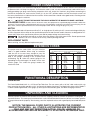
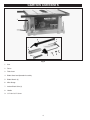
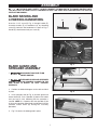
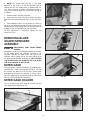
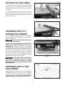
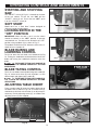
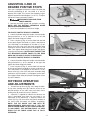
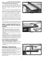
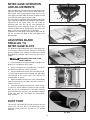
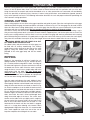
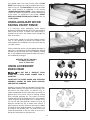
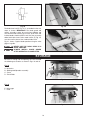
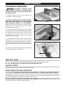
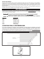
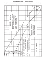
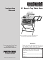
ESPAÑOL: PÁGINA 23
FRANÇAISE : PAGE 43
Instruction
Manual
Double Insulated
10" Bench Top Table Saw
MODEL 3812
Shown assembled with accessory stand model 38129
and accessory outfeed support model 38239.
To learn more about Porter-Cable
visit our website at:
http://www.porter-cable.com
IMPORTANT
Please make certain that the person who is to use
this equipment carefully reads and understands
these instructions before starting operations.
The Model and Serial No. plate is located on the main
housing of the tool. Record these numbers in the
spaces below and retain for future reference.
Model No. _____________________________________
Type __________________________________________
Serial No.______________________________________
Copyright © 2003 PORTER-CABLE Corporation
Part No. 912933 - 09-15-03
SAFETY GUIDELINES - DEFINITIONS
This manual contains information that is important for you to know and understand. This information relates to protecting YOUR SAFETY and PREVENTING EQUIPMENT PROBLEMS. To help you recognize this information, we use the
symbols to the right. Please read the manual and pay attention to these sections.
Indicates an imminently hazardous situation which, if not avoided, will result in death or serious injury.
Indicates a potentially hazardous situation which, if not avoided, could result in death or serious injury.
Indicates a potentially hazardous situation which, if not avoided, may result in minor or moderate injury.
Used without the safety alert symbol indicates potentially hazardous situation which, if not avoided, may
result in property damage.
SOME DUST CREATED BY POWER SANDING, SAWING, GRINDING, DRILLING, AND OTHER
CONSTRUCTION ACTIVITIES contains chemicals known to cause cancer, birth defects or other reproductive harm.
Some examples of these chemicals are:
· lead from lead-based paints,
· crystalline silica from bricks and cement and other masonry products, and
· arsenic and chromium from chemically-treated lumber.
Your risk from these exposures varies, depending on how often you do this type of work. To reduce your exposure to
these chemicals: work in a well ventilated area, and work with approved safety equipment, always wear MSHA/NIOSH
approved, properly fitting face mask or respirator when using such tools.
GENERAL SAFETY RULES
READ AND UNDERSTAND ALL WARNINGS AND OPERATING INSTRUCTIONS BEFORE
USING THIS EQUIPMENT. Failure to follow all instructions listed below, may result in electric shock,
fire, and/or serious personal injury or property damage.
IMPORTANT SAFETY INSTRUCTIONS
Woodworking can be dangerous if safe and proper operating procedures are not followed. As with all machinery, there
are certain hazards involved with the operation of the product. Using the machine with respect and caution will
considerably lessen the possibility of personal injury. However, if normal safety precautions are overlooked or ignored,
personal injury to the operator may result. Safety equipment such as guards, push sticks, hold-downs, featherboards,
goggles, dust masks and hearing protection can reduce your potential for injury. But even the best guard won’t make
up for poor judgment, carelessness or inattention. Always use common sense and exercise caution in the workshop.
If a procedure feels dangerous, don’t try it. Figure out an alternative procedure that feels safer. REMEMBER: Your
personal safety is your responsibility. For additional information please visit our website www.portercable.com.
This machine was designed for certain applications only. Porter-Cable strongly recommends that this
machine not be modified and/or used for any application other than that for which it was designed. If you have any
questions relative to a particular application, DO NOT use the machine until you have first contacted Porter-cable to
determine if it can or should be performed on the product.
Technical Service Manager
Porter-Cable
4825 Highway 45 North
Jackson, TN 38305
(IN CANADA: 505 SOUTHGATE DRIVE, GUELPH, ONTARIO N1H 6M7)
2
FAILURE TO FOLLOW THESE RULES MAY RESULT IN SERIOUS INJURY.
1.
2.
3.
4.
5.
6.
7.
8.
9.
10.
11.
12.
13.
FOR YOUR OWN SAFETY, READ THE INSTRUCTION MANUAL BEFORE OPERATING THE
MACHINE. Learning the machine’s application,
limitations, and specific hazards will greatly
minimize the possibility of accidents and injury.
USE CERTIFIED SAFETY EQUIPMENT. Eye
protection equipment should comply with ANSI
Z87.1 standards, hearing equipment should
comply with ANSI S3.19 standards, and dust mask
protection should comply with MSHA/NIOSH
certified respirator standards. Splinters, air-borne
debris, and dust can cause irritation, injury, and/or
illness.
DRESS PROPERLY. Do not wear tie, gloves, or
loose clothing. Remove watch, rings, and other
jewelry. Roll up your sleeves. Clothing or jewelry
caught in moving parts can cause injury.
DO NOT USE THE MACHINE IN A DANGEROUS
ENVIRONMENT. The use of power tools in damp
or wet locations or in rain can cause shock or
electrocution. Keep your work area well-lit to
prevent tripping or placing arms, hands, and
fingers in danger.
MAINTAIN ALL TOOLS AND MACHINES IN PEAK
CONDITION. Keep tools sharp and clean for best and
safest performance. Follow instructions for lubricating
and changing accessories. Poorly maintained tools and
machines can further damage the tool or machine and/or
cause injury.
CHECK FOR DAMAGED PARTS. Before using the
machine, check for any damaged parts. Check for
alignment of moving parts, binding of moving
parts, breakage of parts, and any other conditions
that may affect its operation. A guard or any other
part that is damaged should be properly repaired
or replaced. Damaged parts can cause further
damage to the machine and/or injury.
KEEP THE WORK AREA CLEAN. Cluttered areas and
benches invite accidents.
KEEP CHILDREN AND VISITORS AWAY. Your shop is
a potentially dangerous environment. Children and visitors
can be injured.
REDUCE THE RISK OF UNINTENTIONAL STARTING.
Make sure that the switch is in the “OFF” position
before plugging in the power cord. In the event of
a power failure, move the switch to the “OFF”
position. An accidental start-up can cause injury.
USE THE GUARDS. Check to see that all guards
are in place, secured, and working correctly to
prevent injury.
REMOVE ADJUSTING KEYS AND WRENCHES
BEFORE STARTING THE MACHINE. Tools, scrap
pieces, and other debris can be thrown at high
speed, causing injury.
USE THE RIGHT MACHINE. Don’t force a
machine or an attachment to do a job for which it
was not designed. Damage to the machine and/or
injury may result.
14.
15.
16.
17.
18.
19.
20.
21.
22.
23.
24.
3
USE RECOMMENDED ACCESSORIES. The use
of accessories and attachments not recommended by Porter-Cable may cause damage to
the machine or injury to the user.
USE THE PROPER EXTENSION CORD. Make
sure your extension cord is in good condition.
When using an extension cord, be sure to use one
heavy enough to carry the current your product will
draw. An undersized cord will cause a drop in line
voltage, resulting in loss of power and overheating.
See the Extension Cord Chart for the correct size
depending on the cord length and nameplate
ampere rating. If in doubt, use the next heavier
gauge. The smaller the gauge number, the heavier
the cord.
SECURE THE WORKPIECE. Use clamps or a vise to
hold the workpiece when practical. Loss of control
of a workpiece can cause injury.
FEED THE WORKPIECE AGAINST THE DIRECTION
OF THE ROTATION OF THE BLADE, CUTTER, OR
ABRASIVE SURFACE. Feeding it from the other
direction will cause the workpiece to be thrown out
at high speed.
DON’T FORCE THE WORKPIECE ON THE
MACHINE. Damage to the machine and/or injury
may result.
DON’T OVERREACH. Loss of balance can make
you fall into a working machine, causing injury.
NEVER STAND ON THE MACHINE. Injury could occur if
the tool tips, or if you accidentally contact the cutting tool.
NEVER LEAVE THE MACHINE RUNNING UNATTENDED. TURN THE POWER OFF. Don’t leave the machine
until it comes to a complete stop. A child or visitor could
be injured.
TURN THE MACHINE “OFF”, AND DISCONNECT THE
MACHINE FROM THE POWER SOURCE before
installing or removing accessories, before adjusting
or changing set-ups, or when making repairs. An
accidental start-up can cause injury.
MAKE YOUR WORKSHOP CHILDPROOF WITH
PADLOCKS, MASTER SWITCHES, OR BY
REMOVING STARTER KEYS. The accidental
start-up of a machine by a child or visitor could
cause injury.
STAY ALERT, WATCH WHAT YOU ARE DOING,
AND USE COMMON SENSE. DO NOT USE THE
MACHINE WHEN YOU ARE TIRED OR UNDER
THE INFLUENCE OF DRUGS, ALCOHOL, OR
MEDICATION. A moment of inattention while
operating power tools may result in injury.
THE DUST GENERATED by certain woods and
wood products can be injurious to your health.
Always operate machinery in well-ventilated areas,
and provide for proper dust removal. Use wood
dust collection systems whenever possible.
ADDITIONAL SAFETY RULES FOR
TABLE SAWS
FAILURE TO FOLLOW THESE RULES MAY RESULT IN SERIOUS INJURY.
1. DO NOT OPERATE THIS MACHINE until it is
assembled and installed according to the
instructions.
10. NEVER perform “free-hand” operations. Use either
the fence or miter gauge to position and guide the
workpiece.
2. OBTAIN ADVICE FROM YOUR SUPERVISOR,
instructor, or another qualified person if you are
not familiar with the operation of this machine.
11. HOLD THE WORKPIECE FIRMLY against the miter
gauge or fence.
12. USE PUSH STICK(S) for ripping a narrow
workpiece.
3. FOLLOW ALL WIRING CODES and recommended
electrical connections.
4. USE THE GUARDS WHENEVER POSSIBLE.
Check to see that they are in place, secured, and
working correctly.
5. AVOID KICKBACK by:
A. keeping blade sharp and free of rust and pitch.
B. keeping rip fence parallel to the saw blade.
C. using saw blade guard and spreader for every
possible operation, including all through
sawing.
D. pushing the workpiece past the saw blade prior
to release.
E. never ripping a workpiece that is twisted or
warped, or does not have a straight edge to
guide along the fence.
F. using featherboards when the anti-kickback
device cannot be used.
G. never sawing a large workpiece that cannot be
controlled.
H. never using the fence as a guide when
crosscutting.
I. never sawing a workpiece with loose knots or
other flaws.
6. ALWAYS USE GUARDS, SPLITTER, AND ANTIKICKBACK FINGERS whenever possible.
13. AVOID AWKWARD OPERATIONS AND HAND
POSITIONS where a sudden slip could cause a
hand to move into the blade.
14. KEEP ARMS, HANDS, AND FINGERS away from
the blade.
15. NEVER have any part of your body in line with the
path of the saw blade.
16. NEVER REACH AROUND or over the saw blade.
17. NEVER attempt to free a stalled saw blade without
first turning the machine “OFF”.
18. PROPERLY SUPPORT LONG OR WIDE
workpieces.
19. NEVER PERFORM LAYOUT, assembly or set-up
work on the table/work area when the machine is
running.
20. TURN THE MACHINE “OFF” AND DISCONNECT
THE MACHINE from the power source before
installing or removing accessories, before adjusting
or changing set-ups, or when making repairs.
21. TURN THE MACHINE “OFF”, disconnect the
machine from the power source, and clean the
table/work area before leaving the machine. LOCK
THE SWITCH IN THE “OFF” POSITION to prevent
unauthorized use.
22. ADDITIONAL INFORMATION regarding the safe
and proper operation of power tools (i.e. a safety
video) is available from the Power Tool Institute,
1300 Sumner Avenue, Cleveland, OH 44115-2851
(www.powertoolinstitute.com). Information is also
available from the National Safety Council, 1121
Spring Lake Drive, Itasca, IL 60143-3201. Please
refer to the American National Standards Institute
ANSI 01.1 Safety Requirements for Woodworking
Machines and the U.S. Department of Labor OSHA
1910.213 Regulations.
7. REMOVE CUT-OFF PIECES AND SCRAPS from
the table before starting the saw. The vibration of the
machine may cause them to move into the saw
blade and be thrown out. After cutting, turn the
machine off. After the blade has come to a
complete stop, remove all debris.
8. NEVER START THE MACHINE with the workpiece
against the blade.
9. NEVER run the workpiece between the fence and a
moulding cutterhead.
SAVE THESE INSTRUCTIONS.
Refer to them often
and use them to instruct others.
4
POWER CONNECTIONS
A separate electrical circuit should be used for your machines. This circuit should not be less than #12 wire and should
be protected with a 20 Amp time lag fuse. If an extension cord is used, use only 3-wire extension cords which have 3prong grounding type plugs and matching receptacle which will accept the machine’s plug. Before connecting the
machine to the power line, make sure the switch (s) is in the “OFF” position and be sure that the electric current is of
the same characteristics as indicated on the machine. All line connections should make good contact. Running on low
voltage will damage the machine.
DO NOT EXPOSE THE MACHINE TO RAIN OR OPERATE THE MACHINE IN DAMP LOCATIONS.
POLARIZED PLUGS: To reduce the risk of electric shock, this equipment has a polarized plug (one blade is wider than
the other). This plug will fit in a polarized outlet only one way. If the plug does not fit fully in the outlet, reverse the plug. If it still
does not fit, contact a qualified electrician to install the proper outlet. Do not change the plug in any way.
MOTOR
Many Porter-Cable tools will operate on either D.C., or single phase 25 to 60 cycle A.C. current and voltage within plus
or minus 5 percent of that shown on the specification plate of the tool. Several models, however, are designed for A.C.
current only. Refer to the specification plate on your tool for proper voltage and current rating.
Do not operate your tool on a current where the voltage is not within correct limits. Do not operate tools
rated A.C. on a D.C. current. To do so may seriously damage the tool.
REPLACEMENT PARTS
When servicing, use only identical replacement parts.
EXTENSION CORDS
Use proper extension cords. Make sure your extension
cord is in good condition. When using an extension
cord, be sure to use one heavy enough to carry the
current of the machine. An undersized cord will cause a
drop in line voltage, resulting in loss of power and
overheating. Fig. D, shows the correct gauge to use
depending on the cord length. If in doubt, use the next
heavier gauge. The smaller the gauge number, the
heavier the cord.
MINIMUM GAUGE EXTENSION CORD
RECOMMENDED SIZES FOR USE WITH STATIONARY ELECTRIC MACHINES
Ampere
Rating
0-6
0-6
0-6
0-6
6-10
6-10
6-10
6-10
10-12
10-12
10-12
10-12
12-16
12-16
12-16
Volts
120
120
120
120
120
120
120
120
120
120
120
120
120
120
120
Total Length
Gauge of
of Cord in Feet
Extension Cord
up to 25
18 AWG
25-50
16 AWG
50-100
16 AWG
100-150
14 AWG
up to 25
18 AWG
25-50
16 AWG
50-100
14 AWG
100-150
12 AWG
up to 25
16 AWG
25-50
16 AWG
50-100
14 AWG
100-150
12 AWG
up to 25
14 AWG
25-50
12 AWG
GREATER THAN 50 FEET NOT RECOMMENDED
Fig. D
FUNCTIONAL DESCRIPTION
FOREWORD
The Porter-Cable Model 3812 is a 10" Bench Top Table Saw. The saw comes with a 26"x20" table surface with a rip
fence extension wing which provides a 24½" rip capacity for ripping 4x8 sheets. The Model 3812 comes with a Riptide™
24 tooth carbide-tipped blade, miter gauge, rip fence, quick release blade guard, and blade changing wrenches.
UNPACKING AND CLEANING
Carefully unpack the machine and all loose items from the shipping container. Remove the protective coating from all
unpainted surfaces. This coating may be removed with a soft cloth moistened with kerosene (do not use acetone, gasoline
or lacquer thinner for this purpose). After cleaning, cover the unpainted surfaces with a good quality household floor paste
wax.
NOTICE: THE MANUAL COVER PHOTO ILLUSTRATES THE CURRENT
PRODUCTION MODEL. ALL OTHER ILLUSTRATIONS ARE REPRESENTATIVE
ONLY AND MAY NOT DEPICT THE ACTUAL COLOR, LABELING OR
ACCESSORIES AND MAY BE INTENDED TO ILLUSTRATE TECHNIQUE ONLY.
5
CARTON CONTENTS
1
2
4
3
5
6
Fig. 2
1.
Saw
2.
Fence
3.
Table Insert
4.
Blade Guard and Spreader Assembly
5.
Blade Wrench (2)
6.
Miter Gauge
7.
Anchor Block Shim (3)
8.
Handle
9.
1/4"-20x1-3/4" Screw
6
7
8
9
ASSEMBLY
FOR YOUR OWN SAFETY, DO NOT CONNECT THE MACHINE TO THE POWER SOURCE UNTIL
THE MACHINE IS COMPLETELY ASSEMBLED AND YOU READ AND UNDERSTAND THE ENTIRE
INSTRUCTION MANUAL.
BLADE RAISING AND
LOWERING HANDWHEEL
E
D
Insert the 1-3/4" screw (D) Fig. 4, through handle (E).
Assemble handle (E) to handwheel (A) by threading
screw (D) clockwise into handwheel as shown in Fig. 5.
Handle (E) should rotate freely on screw (D).
Fig. 4
E
D
A
Fig. 5
BLADE GUARD AND
SPREADER ASSEMBLY
1.
DISCONNECT MACHINE FROM
POWER SOURCE.
A
2.
THE BLADE GUARD AND SPREADER
ASSEMBLY MUST BE PROPERLY ALIGNED TO THE
SAW BLADE IN ORDER TO HELP PREVENT
KICKBACK.
B
3. Position the blade 90 degrees to the table and lock
in place.
Fig. 6
4. Insert spreader end (A) Fig. 6, of blade guard into
anchor block (B). Push spreader (A) down into holder
until you hear a click, indicating that the spreader is
secured. NOTE: It is important that the spreader (A) be
in the vertical position and pushed straight down into the
spreader anchor block (B) during the assembly
procedure.
5.
Fig. 7 illustrates the blade guard in place.
Fig. 7
7
6. NOTE: The anchor block (B) Fig. 6, has been
adjusted at the factory so that the spreader will be
aligned with the saw blade which is supplied with the
saw. When changing to blades with different widths it
may be necessary to adjust the anchor block (B) Fig. 9,
as follows:
7. Remove table insert and saw blade.
8. Loosen the two screws (C) Fig. 8 (under saw table),
that attach the anchor block (B) Fig. 9, to the saw frame
(E).
9. Three additional shims, two of which are shown at
(D) Fig. 9, are supplied with your saw and can be used as
required between the anchor block (B) and the frame (E)
in order to align the spreader with the saw blade.
10. After adjustment is completed, tighten the two
screws (C) Fig. 8.
C
Fig. 8
B
D
REMOVING BLADE
GUARD/SPREADER
ASSEMBLY
E
DISCONNECT TOOL FROM POWER
SOURCE.
The blade must be in the 90 degree position to the table
for the blade guard and spreader assembly to be
removed. Remove the table insert, pull out on the
spreader release spring (A) Fig. 9A, while pulling up on
the blade guard/spreader assembly (B). NOTE: STORE
THE BLADE GUARD AS SHOWN IN FIG. 31A, WHEN
THE BLADE GUARD IS NOT IN USE.
Fig. 9
B
A
MITER GAGE
The miter gage is shipped completely assembled and is
supplied with a T-slot miter gage bar (A) Fig. 10, that can
be inserted into either one of the two T-slotted miter
gage grooves located in the table top, as shown. The Tslot miter gage can be extended beyond the front of the
table for cross-cutting wide workpieces.
Fig. 9A
MITER GAGE HOLDER
Fig. 11, illustrates the miter gage (D) inserted into the
miter gage holder when not in use.
A
D
Fig. 10
Fig. 11
8
RIP FENCE TO SAW TABLE
1. The rip fence may be used on the right or left hand
side of the saw table. Lift locking handle (A) Fig. 12, and
position the front end of the fence on the front fence rail
as shown.
A
2. While pressing front end of fence firmly against front
fence rail, place rear end of fence down on the rear
fence rail and push down on locking handle (A) Fig. 13,
to lock fence in place.
Fig. 12
FASTENING SAW TO A
SUPPORTING SURFACE
A
The saw MUST be properly secured to a supporting
surface using the four mounting holes, two of which are
shown at (A) Fig. 14.
THE SUPPORTING SURFACE MUST BE
ABLE TO SUPPORT 300LBS.
Fig. 13
A HOLE MUST BE PROVIDED IN THE SUPPORTING
SURFACE TO FACILITATE SAWDUST FALL-THRU
AND REMOVAL. Square the saw on the supporting
surface and mark the location of the four 5/16 inch holes
to be drilled, as shown in Fig. 15. Locate and mark an 11
or 12 inch square centered between the four mounting
holes and cut out and remove the square, as shown in
Fig. 15. This opening will allow sawdust to fall through
the saw base. Fasten the saw to the workbench utilizing
the mounting holes that were just drilled.
A
Fig. 14
FAILURE TO PROVIDE THIS SAW DUST
FALL-THRU AND REMOVAL HOLE WILL ALLOW
SAW DUST TO BUILD-UP AROUND THE MOTOR
WHICH MAY RESULT IN A FIRE HAZARD OR CAUSE
MOTOR DAMAGE.
SAW PLACEMENT
MARKS
FASTENING SAW TO TWO
SAW HORSES
5/16" HOLES
11" OR 12"
SQUARE
CUTOUT
When fastening the saw to two saw horses, position the
four grooves located on the base of the saw cabinet
over the 2x4’s of the saw horse and fasten in place with
suitable hardware (not supplied). CAUTION: THE SAW
HORSES MUST BE ABLE TO SUPPORT 300 LBS.
Fig. 15
9
OPERATING CONTROLS AND ADJUSTMENTS
STARTING AND STOPPING
SAW
The “ON/OFF” switch (A) Fig 16, is located on the front
of the saw cabinet. To turn the saw “ON” pull the
“ON/OFF” switch (A) out. To turn the saw “OFF”, push
in on the “ON/OFF” switch (A).
SOFT START
A
Model 3812 has a “Soft Start” feature designed to
minimize startup reaction torque.
LOCKING SWITCH IN THE
“OFF” POSITION
Fig. 16
IMPORTANT: When the tool is not in use the switch
should be locked in the “OFF” position to prevent
unauthorized use. The tool can be locked in the “OFF”
position using a padlock (A) as shown in Fig. 17.
The padlock should have 3/16" diameter shank with a 2"
throat to insure a proper fit.
BLADE RAISING AND
LOWERING CONTROL
To raise or lower the saw blade, turn handwheel (A) Fig
18. Turning the handwheel counterclockwise lowers the
blade and turning the handwheel clockwise raises the
blade.
THE BLADE TILTING LOCK HANDLE (B)
FIG. 19, MUST BE LOCKED DURING ALL CUTTING
OPERATIONS.
A
Fig. 17
BLADE TILTING CONTROL
To tilt the saw blade, loosen blade tilting lock handle (B)
Fig. 19, rotate outer wheel (C) until the blade is at the
desired angle and tighten lock handle (B).
THE BLADE TILTING LOCK HANDLE (B)
FIG. 19 MUST BE LOCKED DURING ALL CUTTING
OPERATIONS.
A
ADJUSTING TABLE INSERT
Place a straight edge (B) across the table at both ends of
the table insert as shown in Fig. 19A. The table insert (A)
should always be level with the table. If an adjustment is
necessary, turn the adjusting screws (C), as needed. Four
adjusting screws (C) are supplied.
Fig. 18
B
C
C
C
A
B
Fig. 19A
Fig. 19
10
ADJUSTING 0 AND 45
DEGREE POSITIVE STOPS
A
Your saw is equipped with positive stops for rapid and
accurate positioning of the saw blade at 0 and 45
degrees to the table. This saw has the capability to go 2
degrees beyond 0 and 45 degrees (-2º to 47º). To adjust
the positive stops, proceed as follows:
1.
DISCONNECT MACHINE FROM
POWER SOURCE.
2. Remove the blade guard and spreader assembly.
NOTE: SEE THE SECTION “REMOVING BLADE
GUARD/SPREADER ASSEMBLY.”
3. Raise the saw blade to its maximum height.
B
Fig. 20
TO ADJUST POSITIVE STOP AT 0 DEGREES
4. Loosen the blade tilting lock handle, move the blade
tilting mechanism as far as possible to the left and
tighten the blade tilting lock handle.
5. Place a square (A) Fig. 20, on the table with one end
of the square against the blade, as shown, and check to
see if the blade is at 90 degrees to the table. If it is not,
loosen screw (B) a few turns and move the blade tilting
mechanism until the blade measures 90 degrees to the
table. Then tighten blade tilting lock handle and tighten
screw (B) until it bottoms. NOTE: CHECK TO SEE IF THE
TILT INDICATOR POINTER POINTS TO THE ZERO
MARK ON THE SCALE. ADJUST IF NECESSARY.
A
C
Fig. 21
TO ADJUST POSITIVE STOP AT 45 DEGREES
6. Loosen the blade tilting lock handle, move the blade
tilting mechanism as far as possible to the right and
tighten the blade tilting lock handle.
7. Place a square (A) Fig. 21, on the table with one end
of the square against the blade as shown, and check to
see if the blade is at 45 degrees to the table. If it is not,
loosen screw (C) a few turns and move the blade tilting
mechanism until the blade is at 45 degrees to the table.
Then tighten blade tilting lock handle and tighten screw
(C) until it bottoms.
A
B
F
RIP FENCE OPERATION
AND ADJUSTMENTS
D
D
1. To move the rip fence (A) Fig. 22A, along the table,
lift up fence locking lever (B), slide the fence to the
desired location on the table and push down fence
locking lever (B) to lock the fence in position.
2. A pointer is supplied to indicate the distance the
fence is positioned away from the saw blade. If an
adjustment to the pointer (D) is required, loosen the
screws (C) Fig. 22B, that fasten the pointer window to
the fence head and adjust the pointer accordingly.
NOTE: THE RIP SCALE HAS TWO SETS OF
MEASUREMENTS DISPLAYED ON IT. THE TOP
SCALE IS USED WHEN THE RIP FENCE GUIDE RAIL
IS COLLAPSED. THE BOTTOM SCALE IS USED
WHEN THE RIP FENCE GUIDE RAIL IS FULLY
EXTENDED.
Fig. 22A
D
C
Fig. 22B
11
3.
THE RIP FENCE MUST BE PARALLEL
TO THE MITER GAGE SLOT AND SAW BLADE TO
HELP PREVENT KICKBACK WHEN RIPPING.
4. The saw blade is set parallel to the miter gage slot at
the factory and the fence must be parallel to the miter
gage slot and saw blade in order to do accurate work and
help prevent kickback when ripping. To check the
alignment:
5. Position the fence close to the miter gage slot, as
shown in Fig. 22A. Push fence toward saw to insure
alignment screws are in contact with the fence rail. Clamp
the fence to the table by pushing down the locking lever
(B). The fence should be parallel with the miter gage slot.
6. If an adjustment is necessary, proceed as follows:
7. Loosen the two screws and jam nuts (D) Fig. 22A, and
lift up locking lever (B). Then while holding the fence
bracket (F) Fig. 22A firmly toward the rear, move the rear
end of the fence (A), by adjusting the two screws (D) until
the fence is parallel with the miter gage slot. Then push
down locking lever (B). Tighten jam nuts (D) on adjusting
screws.
8. The clamping action of the fence (A) Fig. 23, can be
adjusted by lifting up locking lever (B) and turning nut (E)
clockwise to increase or counterclockwise to decrease
the tension of the clamping action of the fence.
B
H
E
G
Fig. 23
REPLACING THE RIP FENCE
SCALE
A metric scale can be attached to the rip fence as
follows:
1. Extend the rip fence guide rail as far as it will go.
2. Use a pencil and “mark” the guide rail at the “0”
location of the scale and remove the standard scale.
3. Place the metric scale on the guide rail referencing the
“0” mark.
4. Collapse the guide rail and check to see if the “0”
mark is accurate.
5. If an adjustment is necessary, adjust the “0” mark by
loosening nut (G) Fig. 23, and turning screw (H)
clockwise to move the “0” mark to the left, and counter
clockwise to move the “0” mark to the right, once the “0”
is set properly on the rip fence guide rail, turn nut (G)
counterclockwise to lock nut (G) against screw (H).
A
Fig. 24
RIP FENCE EXTENSION
The saw has the capability to increase its ripping
capacity by extending the rip fence guide rails.
To extend the rip fence guide rails pull lever (A) Fig. 24,
to the right, and pull out on the guide rails. Then lock the
extended rails.
C
RIPPING THIN STOCK
B
To adjust the fence, pull up on lever (B) so that the top of
the rip fence can be removed, and repositioned on the
rip fence as shown in Fig. 25. This is only necessary
when the fence guide rails are extended.
When using the guide rails for ripping, the fence must be
positioned as shown in Fig. 25, so that the wood can rest
on the ledge (C,) up against the rip fence.
An auxiliary wood insert can be placed in the gap
between the saw table and the rip fence extension to
add extra support.
Fig. 25
12
MITER GAGE OPERATION
AND ADJUSTMENTS
When straight cross-cutting (blade set 90 degrees to the
table) the miter gage can be used in either table slot.
When bevel cross-cutting (blade tilted) only use the
miter gage in the right table slot where the blade is tilted
away from the miter gage and your hands.
This miter gage is equipped with individually adjustable
index stops at 90 degrees and 45 degrees right and left.
Adjustment to the index stops can be made by
loosening lock nuts (B) Fig. 26, and tightening or
loosening the three adjusting screws (C) until they
contact the other end of stop guard (D) when the miter
gage is at 90 and 45 degrees to the saw blade.
To operate the miter gage, simply loosen lock knob (E)
Fig. 26, and move the body of the miter gage to the
desired angle.
E
B
C
D
Fig. 26
B
A
ADJUSTING BLADE
PARALLEL TO
MITER GAGE SLOTS
Fig. 27
The blade was adjusted parallel to the miter gage slots
at the factory. In order to insure accurate cuts and help
prevent kickback when cutting, this adjustment should
be periodically checked and if necessary, adjusted as
follows:
1.
DISCONNECT MACHINE FROM
POWER SOURCE.
2. Raise the blade to its highest position and adjust the
blade so it is 90 degrees to the table.
Fig. 27A
3. Select a tooth on the saw blade that is set to the
left. Mark this tooth with a pencil or marker.
4. Using a combination square, place the body (A) Fig.
27, of the square against the miter gage slot and adjust
the blade (B) of the square until it just touches the
marked tooth, as shown.
A
5. Rotate the blade and check the same marked blade
tooth at the rear of the saw table in the same manner, as
shown in Fig. 27A.
6. If the front and back measurements, shown in Figs.
27 and 27A, are not identical, loosen the four trunnion
bolts (A) Fig. 28, underneath the saw table. Carefully
grasp and move the saw frame until the blade is parallel
to the miter gage slot. Then tighten the four trunnion
bolts securely.
Fig. 28
B
DUST PORT
The saw has a dust port (B) Fig. 28A, located at the rear
of the saw. The dust port is for connecting a dust
collection system to the saw. The port is 2-1/2" outside
diameter.
Fig. 28A
13
OPERATIONS
Common sawing operations include ripping and cross-cutting plus a few other standard operations of a fundamental
nature. As with all power tools, there is a certain amount of hazard involved with the operation and use of the tool.
Using the tool with the respect and caution demanded as far as safety precautions are concerned, will considerably
lessen the possibility of personal injury. However, if normal safety precautions are overlooked or ignored, personal
injury to the operator can result. The following information describes the safe and proper method for performing the
most common sawing operations.
CROSS-CUTTING
Cross-cutting requires the use of the miter gage to position and guide the work. Place the work against the miter gage
and advance both the gage and work toward the saw blade, as shown in Fig. 32. The miter gage may be used in either
table slot. When bevel cutting (blade tilted), use the miter gage slot that does not cause interference of your hand or
miter gage with the saw blade guard. The saw guard must always be used for all through cutting.
Start the cut slowly and hold the work firmly against the miter gage and the table. One of the rules in running a saw is
that you never hang onto or touch a free piece of work. Hold the supported piece, not the free piece that is cut off. The
feed in cross-cutting continues until the work is cut in two, and the miter gage and work are pulled back to the starting
point. Before pulling the work back it is good practice to give the work a little sideways shift to move the work slightly
away from the saw blade. Never pick up any short length of free work from the table while the saw is running.
WARNING: NEVER USE THE FENCE AS A CUTOFF GAGE WHEN CROSS-CUTTING.
For added safety and convenience the miter gage can
be fitted with an auxiliary wood-facing. This auxiliary
wood-facing can be fastened to the front of the miter
gage by using two wood screws through the slots
provided in the miter gage body and into the woodfacing.
RIPPING
Ripping is the operation of making a length-wise cut
through a board, as shown in Fig. 33, and the rip fence
(A) is used to position and guide the work. One edge of
the work rides against the rip fence while the flat side of
the board rests on the table. Since the work is pushed
along the fence, it must have a straight edge and make
solid contact with the table. The saw guard must
always be used. The guard has anti-kickback fingers to
help prevent kickback and a spreader to help prevent
the saw kerf from closing and binding the blade.
Fig. 32
Start the motor and advance the work, holding it down
against the fence. Never stand in the line of the saw cut
when ripping. Hold the work with both hands and push it
along the fence and into the saw blade as shown in Fig.
33. After the workpiece is on the table the work can then
be fed through the saw blade with one hand, as shown in
Fig. 34. After the work is beyond the saw blade and antikickback fingers the feed can continue to the end of the
table, after which the work is lifted and brought back
along the outside edge of the fence. The cut-off stock
remains on the table or tilts up slightly and is caught by
the rear end of the guard or slides off the table to the
floor. If the cut-off stock remains on the table it is not
touched with the hands until the saw blade is stopped,
unless it is a large piece allowing safe removal. When
ripping boards longer than three feet, it is recommended
that a work support be used at the rear of the saw to
keep the workpiece from falling off the saw table.
Fig. 33
Fig. 34
14
If the ripped work is less than 4 inches wide, a PUSH
STICK should always be used to complete the feed, as
shown in Fig. 35. The PUSH STICK can easily be made
from scrap material as explained in the section
“CONSTRUCTING PUSH STICK.” When ripping stock
2 inches or narrower, assemble an auxiliary wood facing
to the fence, as explained in the section “USING
AUXILIARY WOOD FACING ON RIP FENCE” and use
a PUSH STICK.
USING AUXILIARY WOOD
FACING ON RIP FENCE
Fig. 35
It is necessary when performing some special
operations to add wood facing (A) Fig. 36, to one or both
sides of the rip fence, as shown. The wood facing is
attached to the fence with wood screws through the
holes in the fence.
A
A wood facing should be used when ripping material
such as thin paneling to prevent the material from
catching between the bottom of the rip fence and the
saw table surface.
Further information on the safe and proper operation of
table saws is available in the Porter Cable/Delta “Getting
the Most Out of Your Table Saw” How-To-Book, Catalog
No. 11-400. Additional information on table saw safety is
also available by writing to:
Fig. 36
NATIONAL SAFETY COUNCIL
1121 Spring Lake Drive
Itasca, IL 60143-3201
USING ACCESSORY
DADO HEAD
DO NOT USE A “WOBBLE” DADO
BLADE, OR A DADO BLADE LARGER THAN 6"
DIAMETER.
IMPORTANT: THE BLADE GUARD AND SPREADER
ASSEMBLY CANNOT BE USED WHEN DADOING,
AND MUST BE REMOVED.
Fig. 37
Dadoing is cutting a rabbet or wide groove into the work.
Most dado head sets are made up of two outside saws
and four or five inside cutters, as shown in Fig. 37.
Various combinations of saws and cutters are used to cut
grooves from 1/8" to 13/16" for use in shelving, making
joints, tenoning, grooving, etc. The cutters are heavily
swaged and must be arranged so that this heavy portion
falls in the gullets of the outside saws, as shown in Fig.
38. The saw and cutter overlap is shown in Fig. 39, (A)
being the outside saw, (B) an inside cutter, and (C) a
paper washer or washers which can be used as needed
to control the exact width of groove. A 1/4" groove is cut
by using the two outside saws. The teeth of the saws
should be positioned so that the raker on one saw is
beside the cutting teeth on the other saw.
Fig. 38
15
Fig. 39
Fig. 40
The dado head set (D) Fig. 40, is assembled to the saw
arbor as shown. IMPORTANT: The blade guard and
splitter assembly cannot be used when dadoing and
must be removed. Auxiliary jigs, fixtures, push sticks and
feather boards should also be used. Also, the accessory
dado head table insert Delta model 38122 (E) Fig. 40,
must be used in place of the standard table insert.
Fig. 41, shows a typical dado operation using the miter
gage as a guide.
NEVER USE THE DADO HEAD IN A
BEVEL POSITION.
ALWAYS INSTALL BLADE GUARD
AFTER OPERATION IS COMPLETED.
Fig. 41
STORAGE
For ease in storing and transporting, the saw can hold
the following accessories as shown in Figs. 42 and 43.
Fig. 42
A
A - Wrenches
B - Blade guard/Spreader assembly
C - Fence
D. - Extra Blade
D
B
C
Fig. 42
Fig. 43
E - Miter gage
F - Cord
F
E
Fig. 43
16
MAINTENANCE
CHANGING THE BLADE
1.
DISCONNECT MACHINE FROM
POWER SOURCE. USE ONLY 10" DIAMETER SAW
BLADES RATED FOR 4600 RPM OR HIGHER WITH
5/8" ARBOR HOLES.
2. Remove the table insert (A) Fig. 44, and raise the
saw blade to its maximum height.
A
3. Remove the blade guard and spreader assembly.
NOTE: THE BLADE MUST BE IN THE 90 DEGREE
POSITION TO THE TABLE FOR THE BLADE GUARD
AND SPREADER ASSEMBLY TO BE REMOVED.
Remove the table insert, pull out on the spreader release
spring (A) Fig. 45, while pulling up on the blade
guard/spreader assembly (B).
Fig. 44
B
4. Using the open end wrench (B) Fig. 46, place open
end of wrench on flats on inside blade flange to keep the
saw arbor from rotating and remove arbor nut (C) with
the closed end of wrench (D). Turn nut (C)
counterclockwise to remove. Remove outside blade
flange (E) and saw blade (F).
A
5. Install new blade, making certain teeth of blade are
pointing down at the front of the saw table and
assemble the outside blade flange (E) Fig. 46, and arbor
nut (C). Tighten nut (C) with wrench (D) by turning nut
clockwise while holding arbor steady with other wrench
(B).
Fig. 45
D
B
6. Replace the table insert, blade guard and spreader
assembly, and store the two wrenches.
E
C
F
Fig. 46
KEEP TOOL CLEAN
Periodically blow out all air passages with dry compressed air. Clean all plastic parts with a soft damp cloth. NEVER use
solvents to clean plastic parts. They could possibly dissolve or otherwise damage the material.
WEAR SAFETY GLASSES WHILE USING COMPRESSED AIR.
FAILURE TO START
Should your tool fail to start, check to make sure the prongs on the cord plug are making good contact with the outlet.
Also, check for blown fuses or open circuit breakers in the line.
BRUSH INSPECTION AND LUBRICATION
For your continued safety and electrical protection, brush inspection and replacement on this tool should ONLY be
performed by an AUTHORIZED PORTER-CABLE SERVICE STATION or a PORTER-CABLE SERVICE CENTER.
At approximately 100 hours of use, take or send your tool to your nearest Authorized Porter-Cable Service Station to
be thoroughly cleaned and inspected; worn parts replaced, when necessary, relubricated with fresh lubricant, if
required; reassembled with new brushes; and performance tested.
Any loss of power before the above maintenance check may indicate the need for immediate servicing of your tool.
DO NOT CONTINUE TO OPERATE TOOL UNDER THIS CONDITION. If proper operating voltage is present, return
your tool to the service station for immediate service.
17
SERVICE AND REPAIRS
All quality tools will eventually require servicing or replacement of parts due to wear from normal use. These operations,
including brush inspection and replacement, should ONLY be performed by either an AUTHORIZED PORTER-CABLE
SERVICE STATION or a PORTER-CABLE•DELTA FACTORY SERVICE CENTER. All repairs made by these agencies are fully
guaranteed against defective material and workmanship. We cannot guarantee repairs made or attempted by anyone other
than these agencies.
Should you have any questions about your tool, feel free to write us at any time. In any communications, please give all
information shown on the nameplate of your tool (model number, type, serial number, etc.).
ACCESSORIES
A complete line of accessories is available from your Porter-Cable•Delta Supplier, Porter-Cable•Delta Factory Service
Centers, and Porter-Cable Authorized Service Stations. Please visit our Web Site www.portercable.com for a catalog
or for the name of your nearest supplier.
Since accessories other than those offered by Porter-Cable•Delta have not been tested with
this product, use of such accessories could be hazardous. For safest operation, only PorterCable•Delta recommended accessories should be used with this product.
DO NOT USE A “WOBBLE” DADO BLADE, OR A DADO BLADE LARGER THAN 6" DIAMETER.
CATALOG #
38121
38122
12910
12911
12912
38129
38239
DESCRIPTION
Blade Insert
Dado blade Insert
10" Blade 24 teeth
10" Blade 40 teeth
10" Blade 60 teeth
Folding Stand
Outfeed Support
CONSTRUCTING A FEATHERBOARD
Fig. 47, illustrates dimensions for making a typical featherboard. The material which the featherboard is constructed
of, should be a straight piece of wood that is free of knots and cracks. Featherboards are used to keep the work in
contact with the fence and table and help prevent kickbacks. Clamp the featherboards to the fence and table so that
the leading edge of the featherboards will support the workpiece until the cut is completed. Use featherboards for all
non “thru-sawing” operations where the guard and spreader assembly must be removed (see Fig. 48). Always replace
the guard and spreader assembly when the non thru-sawing operation is completed.
Fig. 47
Fig. 48
18
CONSTRUCTING A PUSH STICK
19
1/2" SQUARES
CUT OFF HERE TO
PUSH 1/2" WOOD
CUT OFF HERE TO
PUSH 1/4" WOOD
NOTCH TO HELP
PREVENT HAND
FROM SLIPPING
MAKE FROM 1/2" OR 3/4"
WOOD OR THICKNESS
LESS THAN WIDTH OF
MAT’L. TO BE CUT
PUSH STICK
When ripping work less than 4 inches wide, a push stick should be used to complete the feed and could easily be
made from scrap material by following the pattern shown.
NOTES
20
NOTES
21
PORTER-CABLE LIMITED
ONE YEAR WARRANTY
Porter-Cable warrants its Professional Power Tools for a period of one year from the date of original
purchase. We will repair or replace at our option, any part or parts of the product and accessories
covered under this warranty which, after examination, proves to be defective in workmanship or
material during the warranty period. For repair or replacement return the complete tool or accessory,
transportation prepaid, to your nearest Porter-Cable Service Center or Authorized Service Station.
Proof of purchase may be required. This warranty does not apply to repair or replacement required
due to misuse, abuse, normal wear and tear or repairs attempted or made by other than our Service
Centers or Authorized Service Stations.
ANY IMPLIED WARRANTY, INCLUDING THE IMPLIED WARRANTIES OF MERCHANTABILITY AND
FITNESS FOR A PARTICULAR PURPOSE, WILL LAST ONLY FOR ONE (1) YEAR FROM THE DATE
OF PURCHASE.
To obtain information on warranty performance please write to: PORTER-CABLE CORPORATION,
4825 Highway 45 North, Jackson, Tennessee 38305; Attention: Product Service. THE FOREGOING
OBLIGATION IS PORTER-CABLE’S SOLE LIABILITY UNDER THIS OR ANY IMPLIED WARRANTY
AND UNDER NO CIRCUMSTANCES SHALL PORTER-CABLE BE LIABLE FOR ANY INCIDENTAL OR
CONSEQUENTIAL DAMAGES. Some states do not allow limitations on how long an implied warranty
lasts or the exclusion or limitation of incidental or consequential damages, so the above limitation or
exclusion may not apply to you.
This warranty gives you specific legal rights and you may also have other legal rights which vary from
state to state.
22
PORTER-CABLE • DELTA SERVICE CENTERS
(CENTROS DE SERVICIO DE PORTER-CABLE • DELTA)
(CENTRE DE SERVICE PORTER-CABLE • DELTA)
Parts and Repair Service for Porter-Cable • Delta Power Tools are Available at These Locations
(Obtenga Refaccion de Partes o Servicio para su Herramienta en los Siguientes Centros de Porter-Cable • Delta)
(Locations où vous trouverez les pièces de rechange nécessaires ainsi qu’un service d’entretien)
ARIZONA
Tempe 85282 (Phoenix)
2400 West Southern Avenue
Suite 105
Phone: (602) 437-1200
Fax: (602) 437-2200
CALIFORNIA
Ontario 91761 (Los Angeles)
3949A East Guasti Road
Phone: (909) 390-5555
Fax: (909) 390-5554
San Leandro 94577 (Oakland)
3039 Teagarden Street
Phone: (510) 357-9762
Fax: (510) 357-7939
ILLINOIS
Addison 60101 (Chicago)
400 South Rohlwing Rd.
Phone: (630) 424-8805
Fax: (630) 424-8895
MINNESOTA
Minneapolis 55429
5522 Lakeland Avenue North
Phone: (763) 561-9080
Fax: (763) 561-0653
Cleveland 44125
8001 Sweet Valley Drive
Unit #19
Phone: (216) 447-9030
Fax: (216) 447-3097
Woodridge 60517 (Chicago)
2033 West 75th Street
Phone: (630) 910-9200
Fax: (630) 910-0360
MISSOURI
North Kansas City 64116
1141 Swift Avenue
Phone: (816) 221-2070
Fax: (816) 221-2897
OREGON
Portland 97230
4916 NE 122 nd Ave.
Phone: (503) 252-0107
Fax: (503) 252-2123
MARYLAND
Elkridge 21075 (Baltimore)
7397-102 Washington Blvd.
Phone: (410) 799-9394
Fax: (410) 799-9398
St. Louis 63119
7574 Watson Road
Phone: (314) 968-8950
Fax: (314) 968-2790
COLORADO
Arvada 80003 (Denver)
8175 Sheridan Blvd., Unit S
Phone: (303) 487-1809
Fax: (303) 487-1868
MASSACHUSETTS
Braintree 02185 (Boston)
719 Granite Street
Phone: (781) 848-9810
Fax: (781) 848-6759
NEW YORK
Flushing 11365-1595 (N.Y.C.)
175-25 Horace Harding Expwy.
Phone: (718) 225-2040
Fax: (718) 423-9619
FLORIDA
Davie 33314 (Miami)
4343 South State Rd. 7 (441)
Unit #107
Phone: (954) 321-6635
Fax: (954) 321-6638
Tampa 33609
4538 W. Kennedy Boulevard
Phone: (813) 877-9585
Fax: (813) 289-7948
Franklin 02038 (Boston)
Franklin Industrial Park
101E Constitution Blvd.
Phone: (508) 520-8802
Fax: (508) 528-8089
NORTH CAROLINA
Charlotte 28270
9129 Monroe Road, Suite 115
Phone: (704) 841-1176
Fax: (704) 708-4625
MICHIGAN
Madison Heights 48071 (Detroit)
30475 Stephenson Highway
Phone: (248) 597-5000
Fax: (248) 597-5004
OHIO
Columbus 43214
4560 Indianola Avenue
Phone: (614) 263-0929
Fax: (614) 263-1238
GEORGIA
Forest Park 30297 (Atlanta)
5442 Frontage Road,
Suite 112
Phone: (404) 608-0006
Fax: (404) 608-1123
PENNSYLVANIA
Willow Grove 19090
520 North York Road
Phone: (215) 658-1430
Fax: (215) 658-1433
TEXAS
Carrollton 75006 (Dallas)
1300 Interstate 35 N, Suite 112
Phone: (972) 446-2996
Fax: (972) 446-8157
Houston 77038
4321 Sam Houston Parkway, West
Suite 180
Phone: (281) 260-8887
Fax: (281) 260-9989
WASHINGTON
Auburn 98001(Seattle)
3320 West Valley HWY, North
Building D, Suite 111
Phone: (253) 333-8353
Fax: (253) 333-9613
Authorized Service Stations are located in many large cities. Telephone 800-487-8665 or 731-541-6042 for assistance locating one. Parts and
accessories for Porter-Cable • Delta products should be obtained by contacting any Porter-Cable • Delta Distributor, Authorized Service Center,
or Porter-Cable • Delta Factory Service Center. If you do not have access to any of these, call 888-848-5175 and you will be directed to the
nearest Porter-Cable • Delta Factory Service Center. Las Estaciones de Servicio Autorizadas están ubicadas en muchas grandes ciudades. Llame
al 800-487-8665 ó al 731-541-6042 para obtener asistencia a fin de localizar una. Las piezas y los accesorios para los productos Porter-Cable
• Delta deben obtenerse poniéndose en contacto con cualquier distribuidor Porter-Cable • Delta, Centro de Servicio Autorizado o Centro de
Servicio de Fábrica Porter-Cable • Delta. Si no tiene acceso a ninguna de estas opciones, llame al 888-848-5175 y le dirigirán al Centro de
Servicio de Fábrica Porter-Cable • Delta más cercano. Des centres de service agréés sont situés dans beaucoup de grandes villes. Appelez au
800-487-8665 ou au 731-541-6042 pour obtenir de l’aide pour en repérer un. Pour obtenir des pièces et accessoires pour les produits PorterCable • Delta, s’adresser à tout distributeur Porter-Cable • Delta, centre de service agréé ou centre de service d’usine Porter-Cable • Delta. Si
vous n’avez accès à aucun de ces centres, appeler le 888-848-5175 et on vous dirigera vers le centre de service d’usine Porter-Cable • Delta le
plus proche.
CANADIAN PORTER-CABLE • DELTA SERVICE CENTERS
ALBERTA
Bay 6, 2520-23rd St. N.E.
Calgary, Alberta
T2E 8L2
Phone: (403) 735-6166
Fax: (403) 735-6144
MANITOBA
1699 Dublin Avenue
Winnipeg, Manitoba
R3H 0H2
Phone: (204) 633-9259
Fax: (204) 632-1976
BRITISH COLUMBIA
8520 Baxter Place
Burnaby, B.C.
V5A 4T8
Phone: (604) 420-0102
Fax: (604) 420-3522
ONTARIO
505 Southgate Drive
Guelph, Ontario
N1H 6M7
Phone: (519) 767-4132
Fax: (519) 767-4131
QUÉBEC
1515 Ave.
St-Jean Baptiste, Suite 180
Québec, Québec
G2E 5E2
Phone: (418) 877-7112
Fax: (418) 877-7123
1447, Begin
St-Laurent, (Montréal), Québec
H4R 1V8
Phone: (514) 336-8772
Fax: (514) 336-3505
The following are trademarks of PORTER-CABLE • DELTA (Las siguientes son marcas registradas de PORTER-CABLE • DELTA S.A.) (Les
marques suivantes sont des marques de fabriquant de la PORTER-CABLE • DELTA): Auto-Set®, BAMMER®, B.O.S.S.®, Builder’s Saw®,
Contractor’s Saw®, Contractor’s Saw II™, Delta®, DELTACRAFT®, DELTAGRAM™, Delta Series 2000™, DURATRONIC™, Emc²™, FLEX®, Flying
Chips™, FRAME SAW®, Homecraft®, INNOVATION THAT WORKS®, Jet-Lock®, JETSTREAM®, ‘kickstand®, LASERLOC®, MICRO-SET®, MicroSet®, MIDI LATHE®, MORTEN™, NETWORK™, OMNIJIG®, POCKET CUTTER®, PORTA-BAND®, PORTA-PLANE®, PORTER-CABLE®&(design),
PORTER-CABLE®PROFESSIONAL POWER TOOLS, Posi-Matic®, Q-3®&(design), QUICKSAND®&(design), QUICKSET™, QUICKSET II®,
QUICKSET PLUS™, RIPTIDE™&(design), SAFE GUARD II®, SAFE-LOC®, Sanding Center®, SANDTRAP®&(design), SAW BOSS®, Sawbuck™,
Sidekick®, SPEED-BLOC®, SPEEDMATIC®, SPEEDTRONIC®, STAIR EASE®, The American Woodshop®&(design), The Lumber
Company®&(design), THE PROFESSIONAL EDGE®, THE PROFESSIONAL SELECT®, THIN-LINE™, TIGER®, TIGER CUB®, TIGER SAW®,
TORQBUSTER®, TORQ-BUSTER®, TRU-MATCH™, TWIN-LITE®, UNIGUARD®, Unifence®, UNIFEEDER™, Unihead®, Uniplane™, Unirip®,
Unisaw®, Univise®, Versa-Feeder®, VERSA-PLANE® , WHISPER SERIES®, WOODWORKER’S CHOICE™.
Trademarks noted with ™ and ® are registered in the United States Patent and Trademark Office and may also be registered in other countries.
Las Marcas Registradas con el signo de ™ y ® son registradas por la Oficina de Registros y Patentes de los Estados Unidos y también pueden
estar registradas en otros países. Marques déposées, indiquées par la lettre ™ et ®, sont déposées au Bureau des brevets d’invention et
marques déposées aux Etats-Unis et pourraient être déposées aux autres pays.
Printed in U.S.A. PC-0603-150