1
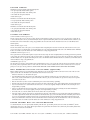
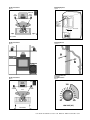
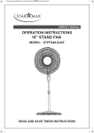
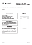
O W N E R ’ S
M A N U A L
RM6700
RM2350
RM2650
SYSTEM
S AT E L L I T E S
CENTER CHANNEL
Big Speaker Sound Without The Big Speaker®
G E T T I N G S TA RT E D
The RM6700 5-Pack carton should contain the following items:
• Four (4) magnetically shielded satellite speakers
• One (1) magnetically shielded center channel speaker
• This manual and other printed materials
• Rubber adhesive pads
The RM2350 carton should contain the following items:
• Two (2) magnetically shielded satellite speakers
• This manual and other printed materials
• Rubber adhesive pads
The RM2650 carton should contain the following items:
• One (1) magnetically shielded center channel speaker
• This manual and other printed materials
• Rubber adhesive pads
SPEAKER PLACEMENT
CENTER CHANNEL SPEAKER (Figures A & B)
Place the center speaker as close to the TV as possible. The most popular placement is right on top of your TV set. It is also fine to place it below the TV
or on the wall directly above the TV. (Use the built-in keyhole slots or an optional wall mounting bracket such as the OmniMount 25RST, available at your
Polk Audio dealer or in the Polk Webstore at http://shop.polkaudio.com. Insert the bracket into the threaded insert on the rear of the RM2650 Center
Channel Speaker.)
FRONT SPEAKERS (Figures A & B)
Place the front satellites about as far apart as you are sitting from them. Avoid placing them less than 2 feet from side walls. Place them at or near your
ear level. If you choose to wall mount them, use the built-in keyhole slot or an optional wall mounting bracket such as the OmniMount 25RST. OmniMount
Brackets are available at your Polk Audio dealer or in the Polk Webstore at http://shop.polkaudio.com.
SURROUND SPEAKERS (Figures A & C)
The best placement for surround channel speakers is high on the side walls, facing each other and slightly behind your listening position. If this placement
is not possible, the speakers may be placed on the rear wall. In either case, mount the speakers two to four feet above the seated listener’s head using either
the built-in keyhole slot or an optional wall mounting bracket such as the OmniMount 25RST. OmniMount Brackets are available at your Polk Audio dealer or
in the Polk Webstore at http://shop.polkaudio.com.
SUBWOOFER (Figures A,B & C)
The subwoofer may be placed in an entertainment center, behind furniture or next to a sofa or chair. The subwoofer may be placed anywhere in the room
but you will get the best performance when it is on the same side of the room as the front satellites and near a wall or corner. It may lie on its side, but
placing it on its feet gives the best performance. NEVER LAY THE SUBWOOFER ON THE AMPLIFIER END—THIS WILL DAMAGE THE AMPLIFIER.
W A L L M O U N T I N G T H E S A T E L L I T E S P E A K E R S (Figures D & D1)
RM2350 Satellite Speakers have two wall mounting options built right in. One is the Keyhole Slot built into the Power Port Bass Vent on the rear of the
speaker, and the other is the Threaded Insert located directly below the Power Port Bass Vent.
Follow these directions to use the Keyhole Slot option:
• On-wall installation of RM speakers requires basic skills and basic tools (drill and screwdriver). If you are in doubt that you possess the necessary
skills or tools, consult your Polk dealer or a professional installer. Otherwise, grab your tools and follow the steps below to safely secure the speakers
to the location of your choice.
• Make sure the locations you have selected for wall-mounting do not conceal electrical wiring or plumbing.
• Hold the speaker in the chosen location to make certain it clears the ceiling, adjacent walls, corners, beams, lighting fixtures and door/window frames.
• If you are certain that there is a stud behind the wall surface, drive a #10 screw (not supplied) through the wall and into the stud leaving the screw
head protruding 1/4" (6mm).
• If there is no stud behind the chosen location, install a #10 wall anchor (not supplied) into the wall by following the wall anchor manufacturer’s
directions, then insert a #10 screw (not supplied), leaving the screw head protruding 1/4" (6mm).
• For masonry walls, use a masonry drill bit and #10 masonry anchor and screw (not included).
• Line up the speaker so that the screw head passes through the large center hole of the keyhole slot. Let the speaker slide straight down, allowing the
screw head to slip behind the smaller end of the keyhole slot. The Threaded Insert gives you more flexibility and choice of mounting location because
you can use an optional fully articulating “ball and socket” type mounting bracket such as the OmniMount 25RST. Simply mount the bracket on the
wall as per the manufacturer's instructions, and insert the threaded end of the articulating arm into the Threaded Insert on the rear of the RM2350.
OmniMount brackets are available at your Polk Audio dealer or in the Polk Webstore at http://shop.polkaudio.com.
CENTER CHANNEL WALL OR CEILING MOUNTING
Use the built-in keyhole slots or an optional, fully articulating “ball and socket” type mounting bracket, such as those made by OmniMount®, with the
threaded insert on the rear of the speaker. When using the keyhole slots option follow the instructions above. When using an articulating bracket follow
the manufacturers’ instructions for installation.
POLK AUDIO CUSTOMER SERVICE: 800-377-7655 (USA & CANADA) • 410-358-3600 (ALL OTHER COUNTRIES)
Speaker Placement
Mounting Options
Figure A
Figure D
SUBWOOFER
CENTER
CHANNEL
LEFT
CHANNEL
RIGHT
CHANNEL
Y
X=Y=Z
• KEYHOLE SLOT
• RANURA
• FENTE EN TROU
DE SERRURE
• SCHLÜSSELLOCHSCHLITZ
• SCANALATURE
Z
X
THREADED INSERT
REAR SPEAKERS
Speaker Placement
Mounting Detail
Figure B
Figure D1
LEFT
CHANNEL
RIGHT
CHANNEL
CENTER
CHANNEL
SUBWOOFER
Speaker Placement
Powered Subwoofer
Low Pass
Recommendation
Figure C
Figure E
SUB
CENTER
CHANNEL
100
Y
LEFT
CHANNEL
RIGHT
CHANNEL
X=Y=Z
X
Z
80
160
LOW PASS (HZ)
REAR SPEAKERS
F O R M O R E I N F O R M AT I O N V I S I T O U R W E B S I T E : W W W. P O L K A U D I O . C O M
C O N N E C T I N G T H E S P E A K E R S T O T H E S Y S T E M (Figures G & H)
Use two conductor 16 gauge or thicker audiophile grade speaker wires. Measure enough wire to reach from your receiver or amp to each speaker plus an
additional 12" to allow moving the speakers or receiver without having to disconnect the wires. One of the terminals on the rear of the speaker is red (+) and
the other black (-). Make certain that you connect the wire from the red (+) terminal of your amplifier to the red (+) terminal on your speaker, and the wire
from the black (-) terminal of the amplifier to the black (-) terminal on your speaker. Most wire has some indication (such as color code, ribbing, or writing)
on one of the two conductors to help maintain consistency. If your speakers sound “thin” with little bass and little to no center image, the chances are that
one of the speaker wires is connected backwards. Double check all connections.
We recommend this system be used with a powered subwoofer (packaged separately) that has a built-in, adjustable low pass filter to separate the bass from
the full range signal. The “subwoofer output” jacks (sometimes labeled “LFE”) on most receivers also contain a fixed low pass filter. If you connect the subwoofer to the receiver’s subwoofer output jack the two filters will interact and reduce the fidelity of your system. If you follow the hook up and the “receiver
set up” instructions below, you will get all of the bass to the subwoofer and get the highest possible performance from your system. DO NOT USE THE “SUBWOOFER OUTPUT” (LFE) JACK ON YOUR RECEIVER TO CONNECT THE SUBWOOFER.
B
•
•
•
•
•
E S T H O O K U P M E T H O D (Figure G)
Connect the left and right front speaker outputs of your receiver or amplifier to the SPEAKER LEVEL INPUTS of the powered subwoofer.
Connect the satellite speakers to the SPEAKER LEVEL OUTPUTS of the subwoofer.
If it is more convenient, parallel wire the subwoofer and satellites from your receiver. (Figure H)
Connect the center channel speaker directly to the center speaker output of your receiver or amplifier.
Connect the surround satellites directly to the rear or surround channel outputs of your receiver or amplifier.
RECEIVER SET UP
All surround sound receivers allow you to match the electronics to your speakers. Refer to the owners manual of your receiver or surround processor to learn
how this is done. To get the best performance from the RM6700, use the following settings:
•
•
•
•
Front Speakers - Set to “Large”
Center Speaker - Set to “Normal” or “Small”
Surround Speakers - Set to “Small”
Subwoofer - Set to “Off” or “None.” This setting may not make sense to you as your RM6700 system is used with a subwoofer,
but really, this is the right setting.
ADJUSTING THE POWERED SUBWOOFER FOR BEST PERFORMANCE
(RM6700 System With Optional Powered Subwoofer)
• Start with the VOLUME level at about the 1 O’clock position. Adjust up or down until you get sufficient bass for your personal taste. Remember that room
position can have a very large affect on perceived bass level.
• Turn the LOW PASS to the middle of the shaded area for best blending between the subwoofer and the satellites. You’ll know the setting is correct when
a high quality recorded male voice sounds full without any chestiness. If vocals sound thin turn this control up—if they sound boomy turn it down
(See Figure E).
SAFE LIMITS OF OPERATION
Your Polk loudspeakers are made with the highest quality materials for years of trouble-free performance. However, damage to loudspeakers can occur when
an amplifier, regardless of its wattage, is made to play at higher listening levels than its power can clearly produce (usually beyond the “1 to 2 O’clock”
position on the volume control).
This results in very high levels of audible distortion, originating in the amplifier, which adds a harsh, gritty sound to the music. Contrary to popular belief,
a speaker is more likely to be damaged by trying to get too much volume from a low-powered amp or receiver than from a high-powered one. If you hear
distortion, turn it down.
M A I N TA I N I N G T H E A P P E A R A N C E O F R M S E R I E S S P E A K E R S
Your new speaker cabinet is made of a rugged material that can be dusted or cleaned with a damp cloth. Avoid harsh detergents and cleaning fluids; they
can permanently damage your speakers’ finish. Gently vacuum the grilles to remove dust.
T E C H N I C A L A S S I S TA N C E O R S E R V I C E
If, after following the hook-up directions, you experience difficulty, please double check all wire connections. Should you isolate the problem
to the speaker, contact the authorized Polk Audio dealer where you made your purchase or call Polk Audio’s Customer Service Department at
1-800-377-7655 (calls from US or Canada only) from 9am to 6pm, Eastern Time, Monday through Friday. You may also contact us via
email [email protected].
POLK AUDIO CUSTOMER SERVICE: 800-377-7655 (USA & CANADA) • 410-358-3600 (ALL OTHER COUNTRIES)
Connecting speaker wires to the satellite and center speaker.
Conexión de los canles del altavoz al altavoz central y
a los altavo ces satelite.
Branchment des câbles de haut-[arleurs aux satellites et
à l’enceinte centrale.
Anschlieben der lautsprecherkabel an die satellitenj-und
den center-lautsprecher.
Collegamento dei cavi satelliti e aguli altoparlanti centrali.
Figure F
Best hook up method.
Método óptimo de conexión.
Meilleure méthode de branchement.
Bestes Anschlussverfahren.
Metodo migliore di collegamento.
Figure G
Loosen hex nut.
Afloje la tuerca hexagonal.
Désserrez l’ecrou hexagonal.
Die Sechskantmutter lockern.
Allentare il dado esagonale.
Insert speaker wire through hole.
Inserte el cable sel altavoz
a trav´s del agujero.
Ins´rez pas la partie isolée du fil.
Das Lautsprecherkabel durch
das loch führen.
Introdurre ol cavo nel foro.
Tighten hex nut.
Apretie la turerca hexagonal.
Serrez écrou hexagonal.
Die sechskantmutter festziehen.
Serrare ol dado esagonale.
Optional hook up method.
Conexión alternativa.
Autre méthode de branchement.
Alternativer anschluss.
Do not insert insulated section
of speaker wire.
Collegamento alternativo.
No inserte la sección aislada
del cable altavoz.
Figure H
N’insérez pas la partie isolé du fil.
Keinen isolierten lautsprecherkabelabschnitt einführen.
Non introdurre ol tratto
isolato del cavo.
TO USE BANANA PLUGS (USA & CANADA
ONLY): CAREFULLY PRY OUT THE BINDING
POST PLUGS (PLASTIC PLUGS ON THE
END OF THE BINDING POSTS) TO EXPOSE
BANANA PLUG HOLES. INSERT BANANA
PLUGS (THIS IS FOR USA & CANADA
OWNERS ONLY).
F O R M O R E I N F O R M AT I O N V I S I T O U R W E B S I T E : W W W. P O L K A U D I O . C O M
SPECIFICATIONS
RM6700 5-PACK SYSTEM
CENTER CHANNEL-RM2650
Shipping Weight (5-Pack):
23 lbs (10.5 kg)
Overall frequency response:
95Hz–24kHz
-3dB limits:
130Hz–20kHz
Recommended Amplification:
20–125 Watts
Sensitivity:
89dB SPL (2.83 Vrms drive level)
Impedance:
compatible with 8 ohm outputs
Bass-Mid Drive Unit:
2–3 1/4" (83mm)
Dynamic Balance drivers,
magnetically shielded,
Polypropylene composite cone,
rubber surround
Tweeter:
1–3/4" (19mm) dome,
self-shielded,
Neodymium magnet,
silk diaphragm
Crossover:
3.1kHz
Enclosure Type:
Vented, Power Port
Dimensions:
11 3/16"W x 4 5/16"H x 5 3/16"D
(28.4cmW x 10.9cm H x 13.1cm D)
FRONT AND REAR SPEAKERSRM2350
Overall frequency response:
95Hz–24kHz
-3dB limits:
130Hz–20kHz
Recommended Amplification:
20–125 Watts
Sensitivity:
89dB SPL @1m
(2.83 Vrms drive level)
Impedance:
compatible with 8 ohm outputs
Bass-Mid Drive Unit:
1–3 1/4" (83mm)
Dynamic Balance
driver magnetically shielded,
Polypropylene composite cone,
rubber surround
Tweeter:
1- 3/4" (19mm) dome,
self-shielded,
Neodymium magnet,
silk diaphragm
Crossover:
3.1kHz
Enclosure Type:
Vented, Power Port
Dimensions:
4 1/16"W x 6 1/2"H x 5"D
(10.3cmW x 16.5cmH x 12.7cmD)
Specifications subject to
change without notice.
POLK AUDIO CUSTOMER SERVICE: 800-377-7655 (USA & CANADA) • 410-358-3600 (ALL OTHER COUNTRIES)
POLK AUDIO LIMITED WARRANTY
Polk Audio, Inc., warrants to the original retail purchaser only. This
warranty will terminate automatically prior to its stated expiration if the
original retail purchaser sells or transfers the Product to any other party.
Polk Audio, Inc., warrants, to the original retail purchaser only, that the
LOUDSPEAKER(S), PASSIVE CROSSOVER COMPONENT(S) and ENCLOSURE on this Polk Audio Loudspeaker Product will be free from defects
in material and workmanship for a period of five (5) years from the date
of original retail purchase from a Polk Audio Authorized Dealer.
Furthermore, Polk Audio, Inc., warrants, to the original retail purchaser
only, that any AMPLIFIER OR OTHER ELECTRONIC COMPONENT that
may be included in this Polk Audio Loudspeaker Product will be free from
defects in material and workmanship for a period of three (3) years from
the date of original retail purchase from a Polk Audio Authorized Dealer.
To allow Polk Audio to offer the best possible warranty service, please
fill out the Product Registration Card(s) and send it to the Factory at the
address provided on the Product Registration Card(s) within ten (10) days
of the date of original purchase.
Defective Products must be shipped, together with proof of purchase, prepaid insured to the Polk Audio Authorized Dealer from whom you purchased
the Product, or to the Factory at 2550 Britannia Boulevard, Suite D, San
Diego, California 92154. Products must be shipped in the original shipping
container or its equivalent; in any case the risk of loss or damage in transit
is to be borne by you. If upon examination at the Factory or Polk Audio
Authorized Dealer it is determined that the unit was defective in materials
or workmanship at any time during this Warranty period, Polk Audio or
the Polk Audio Authorized Dealer will, at its option, repair or replace this
Product at no additional charge, except as set forth below. All replaced
parts and Products become the property of Polk Audio. Products replaced
or repaired under this warranty will be returned to you, within a reasonable time, freight prepaid.
This warranty does not include service or parts to repair damage caused
by accident, disaster, misuse, abuse, negligence, inadequate packing or
shipping procedures, commercial use, voltage inputs in excess of the rated
maximum of the unit, cosmetic appearance of cabinetry not directly attributable to defect in materials or workmanship, or service, repair, or modification of the Product which has not been authorized or approved by Polk
Audio. This warranty shall terminate if the Serial number on the Product
has been removed, tampered with or defaced.
This warranty is in lieu of all other expressed Warranties. If this Product
is defective in materials or workmanship as warranted above, your sole
remedy shall be repair or replacement as provided above. In no event will
Polk Audio, Inc. be liable to you for any incidental or consequential damages
arising out of the use or inability to use the Product, even if Polk Audio,
Inc. or a Polk Audio Authorized Dealer has been advised of the possibility
of such damages, or for any claim by any other party. Some states do not
allow the exclusion or limitation of consequential damages, so the above
limitation and exclusion may not apply to you.
All implied warranties on this Product are limited to the duration of this
expressed Warranty. Some states do not allow limitation on how long an
implied Warranty lasts, so the above limitations may not apply to you.
This Warranty gives you specific legal rights, and you also may have other
rights which vary from state to state.
This Warranty applies only to Products purchased in the United States of
America, its possessions, and U.S. and NATO armed forces exchanges and
audio clubs.
The Warranty terms and conditions applicable to Products purchased in
other countries are available from the Polk Audio Authorized Distributors
in such countries.
F O R M O R E I N F O R M AT I O N V I S I T O U R W E B S I T E : W W W. P O L K A U D I O . C O M
“Polk Audio” and “The Speaker Specialists” are trademarks of Britannia Investment Corporation
used under license by Polk Audio Incorporated.
RM6700-1
Polk Audio
5601 Metro Drive
Baltimore, Maryland 21215
(800) 377-7655