1
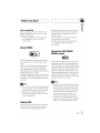
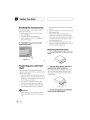
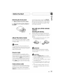
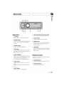
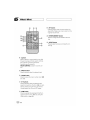
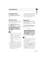
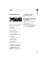
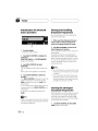
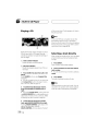
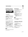
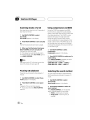
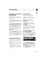
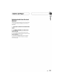
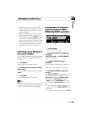
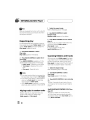
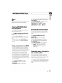
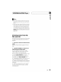
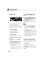
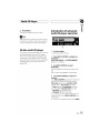
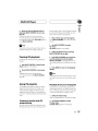
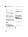
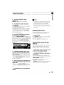
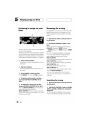
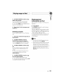
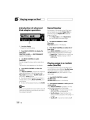
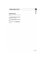
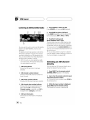
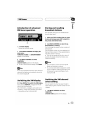
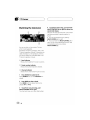
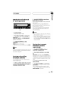
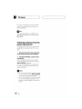
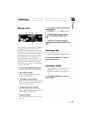
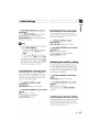
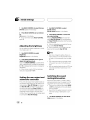
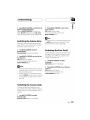
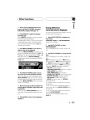
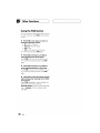
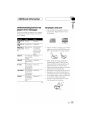
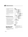
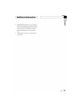
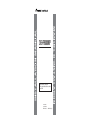
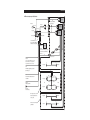
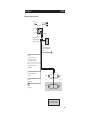
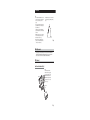
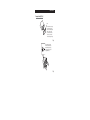
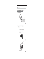
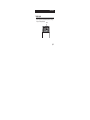
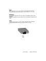
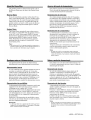
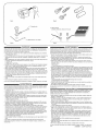
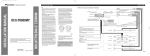
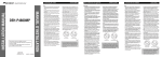
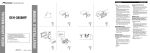
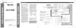
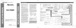
INSTALLATION MANUAL
This product conforms to CEMA cord colors.
Le code de couleur des câbles utilisé pour ce produit est
conforme à CEMA.
Printed in Thailand
Imprimé en Thaïlande
<XRD7112-A/N> UC
<KMMZX> <05H00000>
MANUEL D’INSTALLATION
DEH-P6800MP
Connecting the Units
Note:
O
F
O
STAR
STAR
T
ACC position
OF
ACC
T
F
N
OF
• When an external power amp is being used with
this system, be sure not to connect the blue/white
lead to the amp’s power terminal. Likewise, do not
connect the blue/white lead to the power terminal
of the auto-antenna. Such connection could cause
excessive current drain and malfunction.
• To avoid a short-circuit, cover the disconnected
lead with insulating tape. Insulate the unused
speaker leads without fail. There is a possibility of
a short-circuit if the leads are not insulated.
• To prevent incorrect connection, the input side of
the IP-BUS connector is blue, and the output side
is black. Connect the connectors of the same
colors correctly.
• If this unit is installed in a vehicle that does not
have an ACC (accessory) position on the ignition
switch, the red lead of the unit should be connected
to a terminal coupled with ignition switch ON/OFF
operations. If this is not done, the vehicle battery
may be drained when you are away from the vehicle for several hours. (Fig.1)
N
• This unit is for vehicles with a 12-volt battery and
negative grounding. Before installing it in a recreational vehicle, truck, or bus, check the battery
voltage.
• To avoid shorts in the electrical system, be sure to
disconnect the ≠ battery cable before beginning
installation.
• Refer to the owner’s manual for details on
connecting the power amp and other units, then
make connections correctly.
• Secure the wiring with cable clamps or adhesive
tape. To protect the wiring, wrap adhesive tape
around them where they lie against metal parts.
• Route and secure all wiring so it cannot touch any
moving parts, such as the gear shift, handbrake and
seat rails. Do not route wiring in places that get
hot, such as near the heater outlet. If the insulation
of the wiring melts or gets torn, there is a danger of
the wiring short-circuiting to the vehicle body.
• Don’t pass the yellow lead through a hole into the
engine compartment to connect to the battery. This
will damage the lead insulation and cause a very
dangerous short.
• Do not shorten any leads. If you do, the protection
circuit may fail to work when it should.
• Never feed power to other equipment by cutting
the insulation of the power supply lead of the unit
and tapping into the lead. The current capacity of
the lead will be exceeded, causing overheating.
• When replacing the fuse, be sure to only use a fuse
of the rating prescribed on this unit.
• Since a unique BPTL circuit is employed, never
wire so the speaker leads are directly grounded or
the left and right ≠ speaker leads are common.
• Speakers connected to this unit must be highpower with minimum rating of 50 W and impedance of 4 to 8 ohms. Connecting speakers with output and/or impedance values other than those
noted here may result in the speakers catching fire,
emitting smoke or becoming damaged.
• When this product’s source is switched ON, a control signal is output through the blue/white lead.
Connect to an external power amp’s system remote
control or the car’s Auto-antenna relay control terminal (max. 300 mA 12 V DC). If the car features
a glass antenna, connect to the antenna booster
power supply terminal.
No ACC position
Fig. 1
• The black lead is ground. Please ground this lead
separately from the ground of high-current products such as power amps.
If you ground the products together and the ground
becomes detached, there is a risk of damage to the
products or fire.
• Cords for this product and those for other products
may be different colors even if they have the same
function. When connecting this product to another
product, refer to the supplied manuals of both
products and connect cords that have the same
function.
<ENGLISH>
7 When not connecting a rear speaker lead to a Subwoofer
Antenna jack
Power amp
(sold separately)
Connecting cords with RCA pin
plugs (sold separately)
Rear output
15 cm (5-7/8 in.)
Front output
Power amp
(sold separately)
16 cm (6-1/4 in.)
This product
Power amp
(sold separately)
Subwoofer output
IP-BUS input (Blue)
Fuse
(10 A)
Jack for the Wired Remote Control
Please see the Instruction Manual for the
Wired Remote Control (sold separately).
IP-BUS cable
Multi-CD player
(sold separately)
Blue/white
To system control terminal of the power amp or
Auto-antenna relay control terminal (max. 300
mA 12 V DC).
System remote control
Yellow/black
If you use an equipment with Mute function, wire this
lead to the Audio Mute lead on that equipment. If not,
keep the Audio Mute lead free of any connections.
Front speaker
Yellow
To terminal always supplied with power regardless of
ignition switch position.
Red
To electric terminal controlled by ignition switch (12
V DC) ON/OFF.
+
+
≠
≠
+
Gray
+
Front speaker
Front speaker
≠
Orange/white
To lighting switch terminal.
White
Left
Rear speaker
Black (ground)
To vehicle (metal) body.
+
≠
With a 2 speaker system, do not connect
anything to the speaker leads that are not
connected to speakers.
Rear speaker
Perform these connections when using the
optional amplifier.
Subwoofer
Front speaker
White/black
Green
Green/black
Gray/black
Violet
Violet/black
≠
Right
+
Rear speaker
≠
+
+
≠
≠
+
+
≠
≠
Rear speaker
Subwoofer
Fig. 2
Connecting the Units
<ENGLISH>
7 When using a Subwoofer without using the optional amplifier
Antenna jack
Subwoofer output
15 cm (5-7/8 in.)
Front output
16 cm (6-1/4 in.)
This product
Subwoofer output
IP-BUS input (Blue)
Fuse
(10 A)
Jack for the Wired Remote Control
Please see the Instruction Manual for the
Wired Remote Control (sold separately).
IP-BUS cable
Multi-CD player
(sold separately)
Blue/white
To system control terminal of the power amp or
Auto-antenna relay control terminal (max. 300
mA 12 V DC).
Yellow/black
If you use an equipment with Mute function, wire this
lead to the Audio Mute lead on that equipment. If not,
keep the Audio Mute lead free of any connections.
Yellow
To terminal always supplied with power regardless of
ignition switch position.
Red
To electric terminal controlled by ignition switch (12
V DC) ON/OFF.
+
Black (ground)
To vehicle (metal) body.
Gray
+
Front speaker
Front speaker
≠
Orange/white
To lighting switch terminal.
White
Left
Subwoofer
+
≠
White/black
Green
Green/black
Gray/black
Violet
Violet/black
≠
Right
+
Subwoofer
≠
Note:
Change the initial setting of this unit (refer to the Operation
Manual). The subwoofer output of this unit is monaural.
Fig. 3
Installation
Note:
• Before making a final installation of the unit, temporarily connect the wiring to confirm that the connections are correct and the system works
properly.
• Use only the parts included with the unit to ensure
proper installation. The use of unauthorized parts
can cause malfunctions.
• Consult with your nearest dealer if installation
requires the drilling of holes or other modifications
of the vehicle.
• Install the unit where it does not get in the driver’s
way and cannot injure the passenger if there is a
sudden stop, like an emergency stop.
• The semiconductor laser will be damaged if it
overheats, so don’t install the unit anywhere hot
— for instance, near a heater outlet.
• If installation angle exceeds 60° from horizontal,
the unit might not give its optimum performance.
(Fig. 4)
60°
Fig. 4
DIN Front/Rear-mount
This unit can be properly installed either from “Front” (conventional DIN Front-mount) or
“Rear” (DIN Rear-mount installation, utilizing threaded screw holes at the sides of unit
chassis). For details, refer to the following illustrated installation methods.
DIN Front-mount
Installation with the rubber bush (Fig. 5)
Dashboard
182
Holder
After inserting the holder into the
dashboard, then select the appropriate
tabs according to the thickness of the
dashboard material and bend them.
(Install as firmly as possible using the
top and bottom tabs. To secure, bend
the tabs 90 degrees.)
53
Rubber bush
Screw
Fig. 5
<ENGLISH>
Removing the unit (Fig. 6) (Fig. 7)
Frame
To remove the frame, extend top and
bottom of the frame outwards in
order to unlock it. (When reattaching
the frame, point the side with a
groove downwards and attach it.)
• It becomes easy to remove the
frame if the front panel is released.
Fig. 6
Insert the supplied extraction keys
into the unit, as shown in the figure,
until they click into place. Keeping
the keys pressed against the sides of
the unit, pull the unit out.
Fig. 7
Installation
DIN Rear-mount
Installation using the screw holes on the side of the unit
1. Remove the frame. (Fig. 8)
Frame
To remove the frame, extend top and
bottom of the frame outwards in
order to unlock it. (When reattaching
the frame, point the side with a
groove downwards and attach it.)
• It becomes easy to remove the
frame if the front panel is released.
Fig. 8
2. Fastening the unit to the factory radio mounting bracket.
(Fig. 9) (Fig. 10)
Select a position where the screw holes of the bracket and
the screw holes of the head unit become aligned (are fitted),
and tighten the screws at 2 places on each side. Use either
truss screws (5 × 8 mm) or flush surface screws
(5 × 9 mm), depending on the shape of the screw holes in
the bracket.
10
Fig. 9
11
Screw
Dashboard
or Console
13
Factory radio mounting bracket
12
Fig. 10
<ENGLISH>
Fixing the front panel
If you do not operate the removing and attaching the front panel function, use the supplied
fixing screw to fix the front panel to this unit.
Fixing screw
Fig. 11