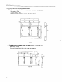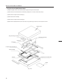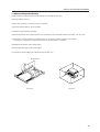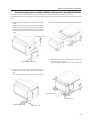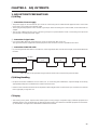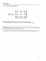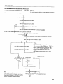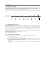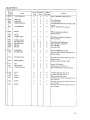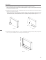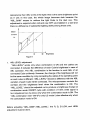
1
TECHNICAL MANUAL (Ver.1.0) MULTI PROJECTION UNIT RM-V2400NA / V2500NA RM-V2400NE / V2500NE PROJECTION SCREEN KIT RMS-V4011/ V5011 PROJECTION FRAME RMF-V4011/ V5011 PROJECTION CABINET RMF-V4011R / V4011CR Caution This symbol refers to a hazard or unsafe practice which can result in personal injury or property damage. Notes: • Pioneer will not be liable for any loss caused by defects of the parts supplied other than by Pioneer. • An damage during shipping will be compensated for only in the case where Pioneer's specific packing materials for shipping are used. • The guarantee of performance is applicable only when the assembly and adjustment described in this technical manual and the adjustment described by the system manual of RM-V2000 have been carried out. • Specifications and design subject to possible modification without notice, due to improvements. R 1 PIONEER RM-V2400 / 2500 MANUAL. This Acrobat (IE: a PDF file) version of the Pioneer RM-V2400 / 2500 manual was made from the original digital document and scanning an existing manual. Because of this, there are many less then perfect pages and hand written comments. As Pioneer is constantly working towards providing the best possible documentation for our products, there may be an improved version of this document available. Please contact your Pioneer representative for additional information. Josh Kairoff Pioneer New Media Technology. October 27, 1997. CONTENTS CHAPTER 1. FEATURES OF PROJECTION CUBE SYSTEM .............................................................. 4 1. FEATURES OF SYSTEM ........................................................................................................................................... 4 2. FEATURES OF MULTI PROJECTION UNIT (RM-V2400N/V2500N) ....................................................................... 4 3. FEATURES OF FRAME TYPE ................................................................................................................................... 5 4. FEATURES OF CABINET TYPE ................................................................................................................................ 5 CHAPTER 2 . GENERAL SPECIFICATIONS ......................................................................................... 6 1. SPECIFICATIONS ...................................................................................................................................................... 6 (1) Multi Projection Unit (RM-V2400N/V2500N) ................................................................................................... 6 (2) Projection Screen Kit(RMS-V4011/V5011)Product Weight:11.0kg/14.0kg .................................................. 13 (3) Projection Frame (RMF-V4011/V5011)Product Weight:26.8kg/28.8kg ........................................................ 14 (4) Projection Cabinet(RMF-V4011R/V4011CR) .................................................................................................. 15 (5) Projection Install Table (RM-V112/RMA-V5010) ........................................................................................... 17 (6) Munting Unit (RMA-V2050/2060) ................................................................................................................... 18 (7) Multi Video Processor(RMD-V3216/3109,RMD-V2170) ................................................................................ 19 (8) Adjustment Control Unit (RU-V107)*Option ................................................................................................ 21 (9) Projection Cabinet (RMF-V4011R) Accessories ............................................................................................ 22 2. SYSTEM DIMENSIONS .......................................................................................................................................... 23 (1) 160-inch (40-inch 4×4screens)…For RMF-V4011 ......................................................................................... 23 (2) 200-inch (50-inch 4×4screens)…For RMF-V5011 ......................................................................................... 24 (3) 160-inch (40-inch 4×4 screens)…For RMF-V4011R ...................................................................................... 25 CHAPTER 3. INSTALLATION AND ASSEMBLY ............................................................................... 26 1. INSTALLATION CONDITIONS ............................................................................................................................... 26 (1) Installing Ground ............................................................................................................................................ 26 (2) Ceiling .............................................................................................................................................................. 27 (3) Front Space ..................................................................................................................................................... 27 (4) Rear Space ...................................................................................................................................................... 27 (5) Number of Units Stacked Up ......................................................................................................................... 27 (6) Prevention of Tilting ....................................................................................................................................... 27 (7) Calculating the Heat Quantity ........................................................................................................................ 28 (8) Temperature and Humidity ............................................................................................................................ 28 (9) Ventilation for system .................................................................................................................................... 29 (10) Condensation ................................................................................................................................................ 30 (11) Visible Angle ................................................................................................................................................. 31 (12) Lighting .......................................................................................................................................................... 34 (13) Effects of Earth Magnetism .......................................................................................................................... 34 (14) Connection with a Power Supply ................................................................................................................ 35 (15) Cables Used .................................................................................................................................................. 36 (16) Semi-outdoor Installation ............................................................................................................................ 36 (17) Precautions for Use of User-Obtained Parts .............................................................................................. 36 2. INSTALLATION AND ASSEMBLY ......................................................................................................................... 37 (1) Confirmation ................................................................................................................................................... 37 (2) Opening the Packaging .................................................................................................................................. 37 (3) Carrying the Units After Opening Packaging ............................................................................................... 43 3. PRECAUTIONS FOR TRANSPORTATION ............................................................................................................. 44 4. ASSEMBLING THE SYSTEM ................................................................................................................................. 45 (1) Assembling the Projection Frame (RMF-V4011/V5011) ............................................................................... 45 (2) Assembling the System ................................................................................................................................. 46 5. SPECIAL INSTALLATION ....................................................................................................................................... 60 (1) Wall inset ......................................................................................................................................................... 60 (2) Diagonal installation ....................................................................................................................................... 60 (3) Architrave processing .................................................................................................................................... 60 (4) Upside down installation ............................................................................................................................... 60 (5) Hanging from ceiling ...................................................................................................................................... 60 CHAPTER 4. ADJUSTMENTS ............................................................................................................ 61 1. ADJUSTMENT PREPARATIONS ........................................................................................................................... 61 (1) Wiring .............................................................................................................................................................. 61 (2) Wiring Handling .............................................................................................................................................. 61 (3) Aging ............................................................................................................................................................... 61 2 GENERAL SPECIFICATIONS 545 Dimensions 380 40 490 540 (Fig.2-1) 7 GENERAL SPECIFICATIONS Power Supply Panel 3 3 1 1 RM-V2400NE/V2500NE RM-V2400NA/V2500NA 4 4 2 2 (Fig. 2-2) No. Name 1 AC inlet 2 AC outlet 3 Main power switch 4 Fuse holder Type Function Connects AC power cord. Connects other multi-projection units. Not linked to main power switch. Note 1) Turns on and off the power supplied to the main unit. Sets into See-saw switch the standby state when turned on. Stores the fuse. No-one except serviceman should touch this part. Note 1) Refer to page 35 [(14) Connection with a power supply 3 Connection]. Control Panel (Fig. 2-3) 8 GENERAL SPECIFICATIONS No. Name Type Function 1 ABL link switch Slide switch Used for switching the control level of the ABL link control voltage when ABL link is ON. 2 Linked input terminal DIN 6PIN Input terminal of ABL signal, remote control signal and RS-232C signal 3 Linked output terminal DIN 6PIN Output terminal of ABL signal, remote control signal, and RS-232C signal 4 Remote control connection ter- Mini jack minal Connected to adjusting remote control (optional) 5 RS-232C port D-sub 25 PIN (Female) RS-232Ccommunicationconnector 6 Control input terminal BNC connector Video input and Y/C input external switching control signal input terminal Normal(video signal input) : Open Select Y/C input : Low(0V) 7 Y (Luminance) input terminal BNC connector Luminance signal input terminal 8 C (Color) input terminal BNC connector Color signal input terminal 9 Video input terminal BNC connector Video signal input terminal 0 Video output terminal BNC connector Video input terminal 9 through-out terminal - TERMINATE switch Slide switch Turns on when terminates the video input terminal 9 at 75 ohm = COMBINATION switch Tact switch Turns on when linked to ABL ~ MULTI switch Tact switch Turns on when used on multi screen ! COLOR MODE switch Tact switch Switches the color temperature. 1:Normal use. 2:Re-exposure @ INPUT switch Tact switch Switches VIDEO input, Y/C input, RGB input. Switches VIDEO input and Y/C input with the external control signal 6 at VIDEO position # POWER switch Tact switch Power OFF : STANDBY (Red LED) lights up Power ON : ON (Green LED) lights up $ STATUS switch Tact switch Accumulated duty time: * Switch which displays setting states of each switch on the screen. % RGB input terminal D-sub 9PIN (Male) RGB signal input terminal ^ RGB input select switch Slide switch Switches RGB signal input terminal type & RGB input terminal (Vertical sync) BNC connector RGB signal vertical sync input terminal * RGB input terminal BNC connector (Horizontal sync/composite sync) RGB signal horizontal sync and composite sync (Only for input signal H/V sync) input terminal ( RGB input terminal (B) BNC connector RGB signal B input terminal ) RGB input terminal (G/composite sync) BNC connector RGB signal G and composite sync (Input signal G on sync) input terminal _ RGB input terminal (R) BNC connector RGB signal R input terminal • To turn off the power, use the POWER switch - of the unit, the RS-232C control, or wired remote control (optional). (If turned off using the main POWER switch or by disconnecting the power cable from the outlet, the settings of the above = to @ switches and the state of the TV SYSTEM and convergence memory will not be recorded on the memory.) Consequently when starting up or stopping the whole system by AC ON/OFF in setup conditions for a demonstration, it is necessary to turn off the power using the above method to record each setting in the memory. (Refer to "CHAPTER 4. ADJUSTMENTS, (5)Equipment Required for Adjustments".) * : Accumulated duty time Counts only when the power is ON. 9 GENERAL SPECIFICATIONS (2) Projection Screen Kit (RMS-V4011/V5011) Product Weight : 11.0 kg/14.0kg 845 148 (1031) (148) 630 (769) (Fig.2-4) Unit:mm The number in parentheses is the dimentsion for RMS-V5011 Accessory Screw rivet ........................................................................................................................... 6 13 GENERAL SPECIFICATIONS (3) Projection Frame (RMF-V4011/V5011) Product Weight : 26.8kg/28.8kg 1201(1352) (769) 630 845(1031) (Fig.2-5) Unit:mm The number in parentheses is the dimension for RMS-V5011 Accessories Metal fixture (R) ................................................................................................................... 1 Metal fixture (L) ................................................................................................................... 1 Stopper ................................................................................................................................. 2 Screw M5x10 ................................................................................................................. 38+2 Screw M5x35 ....................................................................................................................... 6 Screw M5x50 ....................................................................................................................... 4 Hexagon head bolt (with washer) M8x45 .......................................................................... 8 Shield .................................................................................................................................... 1 Rivet ...................................................................................................................................... 2 14 GENERAL SPECIFICATIONS (7) Multi Video Processor (RMD-V3216/V3109, RMD-V2170) 1 Multi Video Processor (RMD-V3216/V3109) Rear View 0 0 299 15 430 D 314 POWER ON OFF MULTI VIDEO PROCESSOR RMD-V3216 16 19 420 482.6 Side View Front View (Fig.2-11) Main Specifications of Multi Video Processor (RMD-V3216/V3109) Input signal Input video signal (Can be expanded up to four systems) 2-line (RMD-V3216), 1-line (RMD-V3109) .... BNC terminal 1 Composite video signal ........................................... ....................................... 1.0 Vp-p (75ohm terminated) 2 Y/C separation signal Y (With sync) ................................ 1.0Vp-p (75ohm) C burst level ............................ 0.286 Vp-p (75ohm) *1 or 2 signal format can be selected *Only 1 has a terminate switch, throughout Input standard sync signal .......................... BNC terminal 1 Composite sync signal ................ 0.286 to 4.0 Vp-p 2 Composite video signal Video level ...................... 0 to 0.714 Vp-p (75ohm) Single level ............................. 0.286 Vp-p (75ohm) *Terminate switch, throughout RS-232C control input 25-pin D-SUB 3 RGB signal Green (Sync on Green) ............................... 1.0 Vp-p SYNC ........................................................... 0.3 Vp-p B.R ................................................................ 0.7 Vp-p Output reference composite sync signal BNC terminal TTL level (Or input reference sync signal throughout) Others Power supply .............................. AC100 to 120V (50/60 Hz) Power consumption ............................................................. ............................ (RMD-V3216, RMD-V3109) 350W, 700VA Operating temperature and humidity range ...................... ........................................................................... 5 °C to 35 °C Below 85% (No condensation) External dimensions (RMD-V3216, RMD-V3109) ............... ................... 482.6 (Width)x420 (Depth)x314 (Height) (mm) (Excluding handle) Weight RMD-V3216 ............................................................... 22.5 kg Output signal RMD-V3109 ............................................................... 22.0 kg Output video signal 16-line (RMD-V3216), 9-line (RMD-V3109) ... BNC terminal 1 Composite sync signal ................ 1.0 Vp-p (75ohm) 2 Y/C separation signal Y (With sync) ................................. 1.0Vp-p (75ohm) C (With burst) Burst level ....... 0.286 Vp-p (75ohm) *1 and 2 signal formats are output simultaneously. Accessories Rack mounting screw M5 .................................................. 8 Rack mounting washer ...................................................... 8 19 GENERAL SPECIFICATIONS 2 Multi Video Processor (RMD-V2170) Front View Side View Rear View (Fig.2-12) Main Specifications of Multi Video Processor (RMD-V2170) Input video signal ......................................... NTSC format Output Input signal band ...................................... Above 4.2 MHz Video output Output signal ............................................................ ...................... NTSC composite video signal (BNC) Output system ............................................... 16-line Standard output level .................. 1Vp-p (75 load) Y/C separation output Output signal ... NTSC Y/C separation signal (BNC) Output system ............................................... 16-line Standard output level ............... Y1 Vp-p (75 load) ...................... C286 mVp-p (75 load, burst signal) Test signal output Output signal ................................................................. ............................ NTSC composite video signal (BNC) Standard output level ....................... 1Vp-p (75 load) Sync signal output ............................... TTL level (BNC) Input Video input Input signal .............................................................. ..................... NTSC composite video signal (BNC) Input system ................................................... 4-line Standard input level .................... 1Vp-p (75 load) Y/C separation Input signal .... NTSC Y/C separation signal (BNC) Input system ................................................... 4-line Standard input level ............... Y:1 Vp-p (75 load) .................... C:286 mVp-p (75 load burst signal) *The video input or Y/C separation input is to be selected by the switch on the rear panel. Reference sync signal input Input signal ............................. Composite sync (BNC) Standard input level ..................................................... ...................................... Composite sync 0.3 to 4 Vp-p Control input Input signal .... Conforms to RS-232C (25-pin, D-sub) *Line up series of RMD-V2110 with 9 OUTPUT CIRCUITS. 20 Power supply voltage ...................... 100 to 120V, 50/60 Hz Power consumption ....................................... 300W/500VA External dimensions ............ 483 (W)x314 (H)x469 (D) mm Weight .......................................................................... 33 kg GENERAL SPECIFICATIONS (8) Adjustment Control Unit (RU-V107)*Option 84 D Î ADJUSTMENT CONTROL UNIT RU-V107 0 ADJ IN 1 2 3 4 5 6 7 8 9 A D B E C F ADJ R ON/OFF G ADJ ON/OFF 187 POWER ADJ B ON/OFF INPUT SEL MAIN MENU 2 /– +/3 DISP CALL ADJ OUT Cable length : 5m 29 (Fig.2-13) Accessories AA dry battery (IEC R6P) ...................................................................................................... 2 Cable (5m) ............................................................................................................................ 3 21 GENERAL SPECIFICATIONS (9) Projection Cabinet (RMF-V4011R) Accessories To attach the multi-projection unit (RM-V2400N) to the conventional RM-V2000A, the RMF-V4011R accessories (metal fixtures) are required. The following lists the required parts. For details of attaching the multi-projection unit, refer to Chapter 3. "4-(2)Assembling the System". Frame R (BNG1207) ....................................................................................................... 1 Frame L (BNG1208) ....................................................................................................... 1 Holder (R) (BNG1150) .................................................................................................... 1 Holder (L) (BNG1151) .................................................................................................... 1 Attachment (R) (BNG1173) ............................................................................................ 2 Attachment (L) (BNG1174) ............................................................................................ 2 Rear holder R (BNG1205) .............................................................................................. 1 Rear holder L (BNG1206) .............................................................................................. 1 Rear panel R (upper) (BMR1069) .................................................................................. 1 Rear panel L (upper) (BMR1070) .................................................................................. 1 Rear panel R (lower) (BMR1071) .................................................................................. 1 Rear panel L (lower) (BMR1072) ................................................................................... 1 Cushion A (BMR1106) ................................................................................................... 1 Cushion B (BMR1107) .................................................................................................... 2 Hinder panel (BMR1075) ............................................................................................... 2 Adjuster (BEF1011) ........................................................................................................ 2 Screw (M5x15) (PMB50P150FZB) ............................................................... 18 (Spare 2) Screw (M5x50) (PMB50P500FZB) ................................................................................. 4 Screw (M6x20) (PMB60P200FZB) ................................................................................. 4 Screw (3x12) (ABA1167) ................................................................................................ 4 Screw (3x8) (BBZ30P080FZK) ..................................................................................... 10 Nut (M8) (NA80FZK) ...................................................................................................... 2 Note : RM-V4000V can assemble with the same accessories. 22 INSTALLATION AND ASSEMBLY (9) Ventilation for system The ventilation method differs according to where the system is installed. The following shows how to provide ventilation for the units according to the place of installation. Refer to these and keep the installation condition in the previous section [(8) Temperature and Humidity] at the system. But when installing your unit, consult your dealer. 1 When there are no walls on all sides (within 1m) As shown in Fig. 3-3, attach the top panel, side panel, and rear panel. (Note) When attaching the rear panel, be careful not to block the vents for the fan of the projection unit. 2 When there is a wall at the back * As shown in Fig. 3-5, mount a large fan to the top panel, provide vents for inhaling air at the bottom panel to blow out air inside. Always leave more than 300 mm between the wall and the back of the unit. (Fig. 3-5) (Fig. 3-3) 3 When blocking the bottom (when placing the projection unit on the floor directly) * Same as 1. (Fig. 3-6) <Note> (Fig. 3-6) *: There should be no obstacles within the 1m area of the unit except for the rear and bottom. If this condition is not followed, construct your own ventilation system (large fan, low temperature by air-conditioning, etc.) according to the site of use. 29 INSTALLATION AND ASSEMBLY (10) Condensation One problem that occurs in the winter season is "Condensation". When the temperature of the room in which the multiprojection unit system is installed rises suddenly, condensation occurs on the screen and lens, thereby the system cannot display its best performance. In such cases, turn off the power once, leave the system off for one hour, and turn on the power again. Increasing the room temperature gradually is another method. 30 INSTALLATION AND ASSEMBLY 4 3P Plug The power cord of this unit has a 3P plug. This is to prevent electric shocks caused by leaked currents. Always connect it to a 3P outlet. 5 Leak Breaker The unit is incorporated with the power line filter to reduce noise. Therefore a 0.5 mA leakage current will flow with each unit. If a leak breaker is equipped, check that its sensitive level is above the total leakage current of the system. Also calculate each unit such as image transmission unit, etc. as 0.5 mA. It is extremely dangerous to supply power from existing wall outlets, etc. Position the final outlet connected to each unit of this system as near as possible to the system. Set the current capacity slightly greater-about more than 25% of the total consumption power. (15) Cables Used Use coaxial cables. Normally use a 3C-2V for less than 20m long. Use 5C-2V for greater lengths. 5C-2V is recommended for high-vision. Adjust the length of the cables. The distance between the transmission system and multi-projection unit should be as short as possible. When the distance is great, consider the thickness of the cable and electrical compensation carefully. The limit is as shown when using the cables to connect the transmission final output terminal and the system. 3C-2V: 15m 5C-2V: 30m To use a longer cable, the VIDEO signal must be corrected. (16) Semi-outdoor Installation This system is basically designed for use indoors. However, if it has to be installed outdoors, take note of the following. • Waterproof and rustproof measures • Temperature difference and humidity difference • Light on the screen (So that it is not exposed to direct sunlight.) • Wind containing salt (17) Precautions for Use of User-Obtained Parts It is recommended that Pioneer products be used for the projection stand, mount unit, etc. Users obtaining these parts separately by themselves should take note of the following. • When obtaining stands and mount units separately, make sure that the system can be installed horizontally. Also calculate strength properly and take adequate measures against tilting of the screen. If the recommended stand and mount unit are not used, Pioneer will bear no responsibility whatsoever for accidents and injuries incurred due to incomplete connections and mounting, natural disasters, etc. • When mounting top board, side board, rear panel obtained separately, use the holes for mounting the Pioneer stand and projection frame. (Refer to Fig. 3-39) 36 INSTALLATION AND ASSEMBLY 2. INSTALLATION AND ASSEMBLY (1) Confirmation 1 Decide the position for installing the system according to the installation conditions in Chapter 3. Check Items [1] Dimensions of installing position, space at the back, distance to the ceiling [2] Floor flatness, strength, roughness [3] Position of power supply [4] Installing location Necessity ti strengthen the floor, wall, etc.(reinforcement cover, sheet, plank, etc.), path used to transport the system, width of passage, if elevator is available , its size and maximum bearing weight, etc. [5] Position, specifications, and structure of a transmission equipment, and image type [6] Model number of equipment used, and their quantity (perform according to list). Check if there is enough equipment for each unit *These procedures must be performed by only one person. (2) Opening the Packaging 1 Packaging specifications [1] Multi Projection Unit (RM-V2400N/V2500N) : 770(W) × 630(H) × 670(D) 43.5kg [2] Projection Screen Kit (RMS-V4011) : 940(W) × 230(H) × 730(D) 15.7kg [3] Projection Frame [4] Projection Cabinet (RMS-V5011) : 1126(W) × 230(H) × 879(D) 20.2kg (RMF-V4011) : 950(W) × 180(H) × 1300(D) (RMF-V5011) : 1160(W) × 250(H) × 1475(D) 31.2kg 35.4kg (RMF-V4011R) : 1006(W) × 859(H) × 1454(D) 68.0kg (RMF-V4011CR) : 1007(W) × 867(H) × 1393(D) 58.0kg 2 Opening the packaging Open from the big ones first and put the small packagings inside the empty big packagings. Also dispose or store the packagings. Do not mix up the opened items with those still in the packaging. Move the empty packagings somewhere else so that they will not come in the way. Next, obtain an assembly space that is as wide as possible. * Turn down the opened packagings upside down to differentiate them from those not opened. Do not lose accessories, the warranty card, etc. 37 INSTALLATION AND ASSEMBLY 3 Multi Projection Unit (RM-V2400N/V2500N) [1] Open the upper carton. [2] Remove the upper carton. [3] Remove the upper pad and remove the AC power cord, ABL cable and instruction manual provided. [4] Take out the unit (must be taken out by two persons). [1] Upper carton [2] [3] Upper pad [4] Accessories (Fig.3-12) 38 INSTALLATION AND ASSEMBLY 4 Projection Screen Kit (RMS-V4011/V5011) * Projection screen kit is double-packaged to maintain its performance. After removing the middle cover protecting its screen, make sure the screen does not get scratched or dirty. [1] Remove the top cover. [2] Remove the band securing the middle cover and remove the middle cover. [3] Gently peel off the black tape pasted at the four sides of the screen. Be careful not to damage the lenticular sheet. [4] Take out the screen unit from the box and stand it on a flat floor, paying attention to its top and bottom. [5] Remove the eight screws for transportation (gold), four protection panels, white sheet at the back of the screen, and the bag containing accessories attached to the top of the frame. * The protection panel is attached with the transportation screws. Keep the removed panel if required. When storing the system, do not remove the outermost protection panel. [6] When opening the packagings of several units first, after opening them, place them in a different place to protect them from damage, and place a sheet over them to protect them from dusts. Instruction manual [2] [1] Middle cover Top cover Band Bag containing accessories [3] Black tape [4] Top Right side Fla t fl oo r Bag containing Transportation screws (Eight : Gold) accessories Protection panel [5] White sheet (Fig.3-13) 39 INSTALLATION AND ASSEMBLY 5 Projection Frame (RMF-V4011/V5011) [1] Open the upper carton and cut the PP bands (eight) securing the internal parts. [2] Remove the two horizontal frame assemblies (packaged in a card box), fixtures (R) and (L). [3] Remove the H-shape frame assembly (L). [4] Remove the base assembly. [5] Remove the H-shape frame assembly (R). [6] Remove the shield attached to the under carton, bag containing accessories, and instruction manual. Upper carton Bag containing accessory Horizontal assembly Fixture (L) Fixture (R) H-shape frame assembly (L) Base assembly H-shape frame assembly (R) Band A Shield (Fig. 3-14) 40 INSTALLATION AND ASSEMBLY 6 Projection Cabinet (RMF-V4011R) [1] Open the upper carton and remove packings B and C, and the instruction manual. [2] Remove the upper carton. [3] Remove the top sheet B and peel off the front and back sheets B. [4] Remove the cabinet. (Hold the handle of the cabinet by two persons.) [5] Remove sheet B. [6] Remove the parts from the under carton. Upper carton Pat Sheet B Pat Sheet B Under carton (Fig. 3-15) 41 INSTALLATION AND ASSEMBLY 7 Projection Cabinet (RMF-V4011CR) [1] Open the upper carton and take out pats A and B and the Instruction Manual. [2] Remove the upper carton. [3] Remove the upper sheet. [4] Take out the cabinet. (This should always be performed by two persons holding the handle. As the front of the cabinet is heavy, be careful not to scratch the screen when taking it out.) [5] Remove the lower sheet. [6] Remove the parts from the under carton. Upper carton Pat B Sheet Pat A Sheet Under carton (Fig. 3-16) 42 INSTALLATION AND ASSEMBLY (3) Carrying the Units After Opening Packaging To carry the screen unit and multi-projection unit after opening the packaging, hold them by the parts shown in the figure, and lift and move them. Handle position Screen Unit (Lifted by one or two persons) Multi-Projection Unit (Must be lifted by two persons) Hold the parts indicated by (Fig. 3-17) • Never drag the system along the floor when moving the units. • The lenticular sheet damages very easily as it is very thin. Therefore move it gently and do not apply excessive shock or vibration to it. • As the panels supporting the screen are very thin and deform easily, be careful that they do not hit or get hooked onto surrounding objects when moving them. 43 INSTALLATION AND ASSEMBLY 4. ASSEMBLING THE SYSTEM (1) Assembling the Projection Frame (RMF-V4011/V5011) Assemble the projection frame as follows. [1] Mount the stopper onto the base assembly and tighten the screws (M5 × 35). (2 × 2 points) [2] Mount the H-shape frame assemblies (R) and (L), and tighten the screws (M5 × 10). (4 × 4 points) [3] Mount the horizontal frame assemblies (two) and tighten the screws (M5 × 10). (4 × 4 points) * As for the positions for tightening the screws in steps [2] and [3], push the frame against the corner fixtures in the two directions indicated by the arrow. [4] Attach the shield to the H-shaped frame assembly (L) using rivet, and paste the magic tape on the H-shaped frame assembly (L) according to the magic tape pasted on the shield. [5] Attach the fixtures (R) and (L) and tighten the screws (M5 × 10). (3 × 2 points) [6] Place the projection unit on the base assembly, and secure the fixtures (R) and (L) and projection unit to each other with the screws (M5 × 10). (2 × 2 points) [7] Secure the movable part of the base assembly with the two screws (M5 × 35). 3 Horizontal frame assembly H-shape frame assembly (L) 4 Rivet A-5 Holder (L) 2 H-shape frame A-7 assembly (R) B-6 Screw (M5 × 35) A-5 Holder (R) 5 Shield Table 2 H-shape frame assembly (L) 1 Screw (M5 × 35) 1 Stopper B-5 Guide fixture 1 Base assembly (Fig. 3-19) 45 INSTALLATION AND ASSEMBLY (2) Assembling the System The basic procedure for assembling the system is as follows. 1 Assemble the projection install table (RM-V112/RMA-V5010). 2 Mount a one-link mount unit . (40-inch only) 3 4 Assemble the projection frame (RMF-V4011/V5011). (Refer to Fig. 3-20) Mount the multi-projection unit (RM-V2400N/V2500N). 5 Mount the projection screen kit (RMS-V4011/V5011). (Refer to Fig. 3-21, 22) 6 Mount the top board , side board , rear panel. 7 Mount the projection unit (RM-V2400N) to the projection cabinet (RMF-V4011R). Mount the frame on the install table by 4 screws. (Fig. 3-20 50 inch) Difference Screen side Rear side Screen side has the difference between the board and frame. (Fig. 3-21 40 inch) Screen side has the difference. (Fig. 3-22 50 inch) The basic procedure for assembling the system for rental-use is as follows. 1 2 Assemble the projection stand (RM-V112). Mount the 2-link/3-link mount unit (RMA-V2050/V2060). 3' Mount the multi-projection unit (RM-V2400N) to the projection cabinet (RMF-V4011R/V4011CR). 4' Mount the projection cabinet (RMF-V4011R/V4011CR). 7' Mount the projection unit (RM-V2400N) to the projection cabinet (RMF-V4011CR). The above procedure is recommended. It is explained below. 1 Projection Install Tables (RM-V112/RMA-V5010) Place the installation tables (RM-V112/RMA-V5010) at the specified position and link them together with the bolts and nuts specified. First tighten the bolts and nuts temporarily, and after all have been linked, check their height differences and if they are horizontal before tightening the nuts and bolts firmly. Do not tighten the adjusters at the legs as their final positions have to be adjusted after assembling all units. To install at a height greater than the installation table when not using this table, make sure the strength is greater than required. 46 INSTALLATION AND ASSEMBLY 4 Multi Projection Unit (RM-V2400N/V2500N) The Multi-Projection Unit is designed to be mounted from the back of the cabinet normally. If sufficient space cannot be left at the back, it can be mounted from the front. Mount from front Mount from back (Fig.3-27) a When mounting from the back [1] Pull the table of the cabinet to the back. (Fig. 3-28) [2] Insert the (M5 × 35) into the holes (Fig. 3-29) on the table. (To prevent the table from moving when placing the projection unit.) [3] Place the multi-projection unit on the table and decide the position. The position should be so that the front of the multi-projection unit will touch the metal fixtures while the sides touch the guide fixtures (right side as viewed from the screen side). (Fig. 3-30) [4] Secure the multi-projection unit to the metal fixtures of the cabinet with the four (M5 × 50). (Fig. 3-31) [5] Remove the inserted into the table at step [2], and push in until the table touches the stopper. Table 48 (Fig. 3-28) (Fig. 3-29) (Fig. 3-30) (Fig. 3-31) INSTALLATION AND ASSEMBLY b When mounting from the front [1] Remove the two stoppers and two metal fixtures from the cabinet. (Fig. 3-32) [2] Pull the table to the front. [3] Insert the screws (M5 × 35) into the holes on the table. [4] Place the multi-projection unit on the table. [5] Attach the metal fixtures to the table. [6] Decide the position of the multi-projection unit and attach it to the metal fixture with the four (M5 × 10). (Fig. 3-33) [7] Remove the screws inserted into the table at step [3], and push in until the stopper can be attached. *As there are no stoppers at the back, be careful not to push the table in excessively. [8] Re-tighten the stopper at the initial position. [9] Pull out the table until it touches the stopper. [10] Secure the cabinet table to the cabinet with the two (M5 × 35). Metal fixtures (Fig.3-32) (Fig.3-33) 49 INSTALLATION AND ASSEMBLY 5 Projection Screen Kit (RMS-V4011/V5011) [1] Mount the screen unit serving as the reference. Basically, mount from the center unit at the bottom. a If the number of units arranged are odd (E.g.: 3 × 3=9 screens) • Adjust the screen unit to the cabinet at the center of the bottom level and temporarily tighten the linking bolts. (Do not tighten tightly.) • Adjust the left and right balance with your hand and tighten the linking bolts tightly so that the two centers coincide. Top view Projection Frame Linking bolt Adjust the left and right balance with your hand. Linking bolt Projection screen Adjust the left and right balance with your hand. Reference Unit (Fig. 3-34) b If the number of units arranged are even (E.g.: 4 × 4=16 screens) • Adjust the screen unit to the right cabinet (or left cabinet) at the center two cabinets of the bottom level and temporarily tighten the linking bolts. (Do not tighten tightly.) • Adjust the left side of the screen unit attached and left side of the cabinet (rights sides if the screen unit was attached to the left cabinet at the center) so that they are aligned precisely with your hand, and tighten the linking bolts. • Join the left side (or right side) screen unit to the unit mounted first as closely as possible. Adjust so that they are aligned precisely Reference Unit (Fig.3-35) 50 INSTALLATION AND ASSEMBLY [2] Join the next screen beside the screen mounted as the reference and mount the remaining screens in order. (Stack them from the bottom to the top.) [3] If necessary, attach the screw rivet (BEC1082) provided as the accessory of RMS-V4011. (Fig. 3-36) (Fig. 3-36) * This part is used to shield the light leaking from the big hole (ø 8) on the outermost side of the left and bottom projection units (diagonally shaded part in Fig. 3-37) after installing the system. Use it if necessary. Screen units with this rivet cannot be attached outside the area indicated by the standing lines in fig. 3-37. (It will not connect to the adjoining units.) (Fig. 3-37) <Note> • Do not mistake the top and bottom of the screen unit. The side with the longer screw projecting out (side with transportation screw) is the top and the side with the 8 mm hole is the bottom. • Before mounting the screen unit to the cabinet, check that the transportation screw, protection panel, and black tape have been removed. (Do not remove the protection panel on the outer-most side when installing the system.) • Always tighten the linking bolts of the cabinet and screen unit with your hands, and tighten them as firmly as possible. • Put on gloves when stacking the screen units for protection and perform in twos. • To prevent the lenticular sheet from damage, mount the screen unit gently and do not subject it to vibration and shock. • When the screen units are stacked, the head of the panel fixing screws and 8 mm holes will engage. When stacking the upper screen unit, make sure that it does not brush the lower screen unit as it has panel screws projecting out. 51 INSTALLATION AND ASSEMBLY 6 Top panel, Side panel, Rear panel As this system is of the rear projection type, it must be enclosed to avoid exposure to external light. (Fig.3-38) Side panel Top panel Side panel (Fig. 3-29) Rear panel (Fig. 3-38) 52 INSTALLATION AND ASSEMBLY 3' Attaching the Multi Projection Unit (RM-V2400N) to the Projection Cabinet (RMFV4011R) The figure shows the assembling procedure of the left attachment. Assemble the right attachment in the same way. The parts on the right side of the screen are R and those on the left side are L from the view point against the screen. (1) Attach the attachments R and L (BNG1173, 1174) to the front of frames R and L (BNG1207, 1208) using the screw (M5 ×15). (3) Insert the claws of the attachments R and L into the rear slits of the multi-projection unit, and attach using the screws (M5 × 15). (1 piece × 2 locations). Frame L (BNG1208) Screw Attachment L (BNG1174) (M5 ×15) (2) Insert the claws of holders R and L (BNG1150, 1151) into the slits of frames R and L, rotate them as shown in the figure, and attach using the screws (M5 × 15). (2 pieces × 2 locations). Holder L Attachment L (BNG1174) *Drop the screw-lock fluid to screws so as not to loosen.(Right and left) (BNG1151) (4) Attach the parts assembled at steps (1) and (2) onto the multi-projection unit. Attach the attachments R and L to frames R and L. Using the screw (M5 × 15) as shown in the figure, and attach the attachments R and L to the rear of the projection unit using the screws (M5 × 50). (2 screws × 2 locations). Screw (M5 × 15) Screw (M5 × 15) 54 Screw (M5 × 50) INSTALLATION AND ASSEMBLY (5) Paste cushion A (BMR1106) to the top board of the multi-projection1234 unit and cushion B (BMR1107) to the two sides at the1234 1234 position shown in the figure after peeling off the seal. (7) Attach the attachments R and L to the unit through the top board of the unit using the screws (M6 × 20) and then attach attachments R and L to the unit from the back using screws (M6 × 20). (2 screws × 2 locations). Screws (M6 × 20) Cushion A (BMR1106) * Paste after adjusting the center of the top board to that of cushion A. Cushion B (BMR1107) Screws (M6 × 20) * Paste without covering the fan. *Drop the screw-lock fluid to screws so as not to loosen. (4 points) (8) Check the Focus and readjust if necessary. (6) Insert the multi-projection unit from the rear of the unit in this state. (9) Attach the cover (BNE1012) to the top board of the unit using the four screws (M5 × 15). Screw (M5 × 15) Cover (BNE1012) Unit 55 INSTALLATION AND ASSEMBLY (10) Attach the adjuster (BEF1011) attached with a nut (M8) to the rear holders R and L (BNG1205, 1206). (12) Attach each rear panel (BMR1069, 1070, 1071, 1072) to the unit and the rear holders R and L using the screws (3 × 8). Furthermore, to cover up the gap at the top of the projection unit, paste the hinder panel (BMR1075) over the top board and projection unit. Adjuster (BEF1011) nut (M8) Hinder panel (BMR1075) Rear holder L (BNG1205) Rear panel L (upper) (BMR1070) Rear panel L (lower) (BMR1072) (11) While tilting the parts assembled at step 10, insert it into the holes on the shoulder of the multi-projection unit and attach with the screws (3 × 12). (2 screws × 2 locations). Furthermore, pull up the adjuster to the top of the unit while rotating it, and pull down the nut to the rear holders R and L while rotating it to secure the projection unit. Screw : M3 × 8 [After Completion] * Tighten the nuts tightly. screws (M3 × 12) 4' Mounting the Projection Cabinet (RMF-V4011R) Projection cabinet can mount to use the conventional method. For details, refer to the RM-V2000A technical manual. 56 INSTALLATION AND ASSEMBLY 7' Mount the multi-projection unit (RM-V2400N) to the Projection Cabinet (RMF-V4011CR) The figure shows how the left side attachment is assembled. Assemble the right attachment in the same way. To differentiate the R and L of the parts, those on the right side of the screen as seen from the front are R and those on the left are L. (1) Attach the engine guide to the projection unit with screws. Attach the engine guide so that the distance between the top edge of the engine guide and the top edge of the unit and the distance between the bottom edge of the engine guide and the bottom edge of the unit are equal. (3) Insert the projection unit from the rear of the cabinet. Screw (M6 × 50) Engine guide (BND1099) (4) Attach fixtures R and L and the engine guide to the projection unit with screws. * Secure the M6 × 20 with a screw-locking compound. (2) Insert the claws of fixtures R (BNG1173) and L (BNG1174) into the slits at the back of the projection unit. * Secure the screws with a screw-locking compound. Screw (M5 × 12) Screw (M6 × 20) Fixtures L (BNG1174) Screw (M5 × 12) 57 INSTALLATION AND ASSEMBLY 9 Removal of RM-V2400N Perform the following steps to remove RM-V2400N from RMF-V4011CR. [1] When removing from the rear 1) Remove the screws of the engine guide and fixtures R and L attached to the cabinet. 2) Remove the screen (Refer to Replacing the Screen in “Chapter 5.1. Maintenance”.) 3) Remove the screws attaching the projection unit and engine guide. 2) Pull out the projection unit. Leave the engine guide and fixtures R and L attached to the projection unit. 4) Push out the projection unit. Leave the engine guide and fixtures R and L attached to the cabinet. (Note) The projection unit should be removed by more than two persons always. [2] When removing from the screen side • Excluding exceptional cases, remove the projection unit from the rear. 1) Before assembling the cabinet, remove the screws at the side securing the fixtures R and L to the projection unit. Keep these screws carefully because they are to be attached again when transporting the cabinet. (Note) If the screws at the side securing the fixtures R and L to the projection unit have not been removed at step 1) : a) Remove the screws securing the fixtures R and L to the cabinet. b) Lift up the rear of the projection unit, and pull it out from the screen side. In this case, the fixtures R and L are attached to the projection unit. 59 INSTALLATION AND ASSEMBLY 5. SPECIAL INSTALLATION (1) Wall inset • If removing the screen after installing the system, the person must go behind the screen (diagonally shaded part of the figure). Therefore when insetting the unit in the wall, careful take this into account before installation. Screen (Fig. 3-43) • When fixing the screen into the wall, space for placing your hand inside the wall at the top, bottom, right, and left will be required in addition to the above in order to attach and remove the screen. (2) Diagonal installation • This system cannot be placed facing upwards or downwards and diagonally. Always place it horizontally. However, Multiprojection unit (RM-V4000NA/V5000NA) alone can be tilted at the up to 45 deg. Installation of special order screens and cabinets should also become possible in the near future. (3) Architrave processing • When enclosing the screen with a frame, etc., add 15 mm to the dimensions of the assembled screen at the top, bottom, left, and right. * Perform framing constructions after assembling the screen. 15 mm 15 mm 15 mm 15 mm (Fig. 3-44) • If light leaks from the rear space after constructions, place a blind plate over the rear. • No one should climb onto the top board. (RMF-V4011/V5011) (4) Upside down installation • Not possible (5) Hanging from ceiling • Not possible 60 CHAPTER 4. ADJUSTMENTS 1. ADJUSTMENT PREPARATIONS (1) Wiring 1 Connection of Power Supply • The power supply can be connected to up to 3 units in a series using the AC outlets of Multi projection units. Connect the three units as one system to the external outlet. • The AC plug of Multi projection unit is a 3P with a ground pin. When connecting it to a normal outlet, use an exclusive 3P AC adapter. • The AC plug of Multi projection unit is a 3P with a ground pin. To prevent electric shocks, connect the ground pin to the ground when connecting the power supply. 2 Connection of signal cable • Use coaxial cables. Normally, if less than 15m, use 3C-2V. If less than 30m, use 5C-2V. The signal transmission equipment and Multi projection units should be as close as possible to each other. 3 Connection of ABL link cable • By connecting the ABL link cables in cascade form, control signals (RS-232C, remote control signal) can be transmitted to all the units. RS-232C Personal Computer OUT or Multi Projection Unit Multi Projection Unit Multi Projection Unit Link cable IN OUT IN OUT Link cable Remote control unit (Up to 16 units can be operated using the remote control unit at one time using the link cable.) (2) Wiring Handling • Except for short-term installations such as events, etc., in normal long-term installations, adjust the length of the wiring appropriately taking into consideration the overall route to be wired. • Make sure the connection terminals are not subjected to direct weight and force. Tie the wires up in short-term use and bind them up properly in long-term use. (3) Aging • After turning on the power, input the 100% white signal or moving images, and perform aging until Multi projection unit stabilizes (about 1 hour). If adjustments are performed without aging, as it takes time until Multi projection unit will warm up and stabilize, convergence and white balance will become incorrect. 61 ADJUSTMENTS (2) TV System The TV system determines the control of the whole unit (convergence, OSD display select, video system select, deflection) according to the signal input. Set it according to the signal input. When TV SYSTEM is set to AUTO • The mode is automatically set to NTSC or PAL according to the input signal (NTSC/PAL). When the TV SYSTEM is set to NTSC • The mode is set to NTSC regardless of the input signal. When the TV SYSTEM is set to PAL • The mode is set to PAL regardless of the input signal. [Precaution to use] Normally, the TV SYSTEM is set to AUTO. If the signals cannot be differentiated between NTSC and PAL (or they are differentiated incorrectly : VCR signal repeatedly dubbed or part of CATV converter, etc.), the TV SYSTEM is set to NTSC or PAL according to the input signal. When the input signal is NTSC or PAL, and the TV SYSTEM is set to NTSC or PAL, it can enable the input to be switched smoothly (little screen noises), and prevent signals from being differentiated incorrectly due to signal disturbances and cuts. In some cases, even if the same TV format is used, more than two types of convergence data will be required. (For example, when there are signal phase differences for every input source, etc.) In such cases, use two types of memories. Switch them using the personal computer. 64 ADJUSTMENTS (6) Giving IDs When several Multi projection units are used to compose the 9 screens or 16 screens (multi-screen), the ID is used to differentiate between Multi projection units. When the units are given IDs, by connecting the ABL link cable, commands can be transmitted by specifying the ID, and it is possible to operate only Multi projection unit corresponding to that ID by remote control operations. <Giving IDs using Personal Computer> Commands: IDC (IDC CLEAR) ;Clears the ID given IDS (ID SET) ;Gives an ID The IDS is valid only when no ID has been given. It will be valid from units nearest to the personal computer (remote control). (Example) 4 screens • When giving IDs first using Personal Computer. Personal Computer Multi Projection Unit Multi Projection Unit Multi Projection Unit ID=11 ID=12 ID=21 Multi Projection Unit ID=22 **AJY 11 IDS ↓ **AJY 12 IDS ↓ **AJY 21 IDS ↓ **AJY 22 IDS By sending commands in this order, IDs can be given to each Multi Projection Unit (connect ABL link cables as above example). The characters that can be used for the IDs are 0 to 9 and A to F, and * (capital and small letters are not differentiated). The * can be used in the following way. ** IDC :Clears IDs given to all units *1AJY :Only units which have IDs whose 2nd digit is 1 enter the adjustment mode. 2* IN1 :The input function of only units which have IDs whose 1st digit is 2 is set to VIDEO. 66 ADJUSTMENTS <Giving IDs Using the Remote Control> key to set the whole screen into the adjustment mode. [1] Press the [2] The main menu will be displayed. Press the ADJ IN 1 key. Select ”1. ID SET/CLEAR/SELECT” [3] Check that the ID display at the top left of the screen is “– –” and press the 1 key. Select “1.ID SET”. If an ID has already been given, press the 0 key, select “0. ID CLEAR” of the main menu, return to “[1] Enter the adjustment mode.” and give the ID. 0 to 9 , A to F keys, and input the ID. [4] As the ID input standby state is set, press the [5] To use the multi-screen unit, return to “[1] Enter the adjustment mode.” and given an ID to the next unit. Note) To return the whole screen to the main menu after giving IDs to the whole screen, press the ADJ IN key. <Selecting the ID Using the Remote Control> Select the screen to be adjusted using the remote control. Example) Select the ID at the bottom left side of the screen (ID=21) as shown in the figure on the right. ID = 11 ID = 12 ID = 21 ID = 22 [1] Set all screens to the adjustment mode using the [2] Select [1. ID SET/CLEAR/SELECT using the [3] Select [2. ID SELECT] using the [4] Press the [5] Only the bottom left side of the screen shows the main menu. The other screens will set into the standby state ( POWER 2 , and ADJ IN , 1 ADJ OUT 2 1 ADJ IN key . key. key. keys (ID=21). keys only are accepted). • To return to the main menu after completing ID SELECT, press the Pressing the ADJ IN MAIN MENU key to keep the ID SELECT state. key will also return to the main menu, but it also clear the ID SELECT state, making it necessary to repeat from step [1] again. To select other screens, press the MAIN MENU key to return to the main menu, and change the ID number set at step [4] above. Note : When the wrong ID has been specified Repeat the above steps [1] to [5]. Perform the same steps when an inappropriate ID (Example : ID=33, etc. in the above screen) has been input. In this case, all screens will set into the standby state. <Precautions for Giving IDs using the Remote Control and Personal Computer> Communication cannot be performed with units connected using the ABL link cable, after units whose IDs have been cleared. When the command “** IDC” shown in the figure on the previous page is performed, only the first unit can be controlled. Using the command “11 IDS” will enable the 2nd unit and onwards to be controlled. When IDs are set as this, the unit connected next can be controlled. 67 ADJUSTMENTS 3. EXAMPLES OF MAIN USES OF MULTI-PROJECTION UNITS (1) Expansion/Individual Switching at Multi Video Processor Side - General example Source NTSC or PAL TV SYSTEM) NTSC Multi Video Processor or PAL Multiprojection Unit AUTO Converter data required at display) One (2) When Switching Source Inputs to Multi Video Processor LDP-1 NTSC Multi Video Processor or PAL Multiprojection Unit LDP-2 * There is phase difference between LDP1 and 2 * Only one image frame data TV SYSTEM) AUTO Converter data required for display) Two * For example, adjust LDP-1 with MEMORY 1 and LDP-2 with MEMORY 3 and switch data by external control when switching LDP . 68 ADJUSTMENTS 4. SCREEN ADJUSTMENTS (1) Adjustment Flowchart The following shows the order for performing the adjustments generally required in the setup of the multi-projection system. For details, see the descriptions on the next page and later. 1 Give ID ↓ 2 Adjust the size of each screen ↓ 3 Adjust the convergence of each screen ↓ ↓ 4 Adjust the joining of the screens (Adjust with the multi-video processor) 5 Check that there is no information missing and color deviation on the moving image. If information is missing or color has deviated, return to 2 and readjust. ↓ 6 Adjust the white balance of each screen. ↓ 7 Adjust the ABL level ↓ 8 Check the ABL level and white balance using the video actually transmitted. If there is deviation, return to 6 and readjust ↓ 9 Adjust the color tone using the video actually transmitted. ↓ 0 Recheck 6 to 8 69 ADJUSTMENTS (2) Convergence Adjustment Flowchart 1 (P. 70) 2 (P. 70) 3 (P. 70) 4 (P. 71) Find the center of the screen Input the adjustment signal Using only green, adjust the center of V STATIC GH STATIC Adjust the size of V SIZE V LIN H SIZE GH LIN Is the Horizontal size standard (93%)? NO 8 YES 5 (P. 72) 6 (P. 72) 7 (P. 72) 70 Adjust joining of peripheral screens in green point convergence mode Adjust linearity of green point convergence mode Adjust green, red, blue color deviation in point convergence mode (P. 85) Adjust H BLK-L and H BLK-R ADJUSTMENTS & numbers correspond to the numbers in the flow- (3) Convergence Adjustment Contents The 1 Measurement of screen center chart. The center can be found easily by pasting threads in the spaces of the protection panels at the screen frame. 2 Adjustment signal input For adjusting size...Frame size picture(EX.LD Test disc GGT1072, FRAME No. 5941),Monoscope, etc. For screen joining, linearity, color adjustment...Use adjustment signals such as , cross-hatch, etc. (EX. LD Test disc GGT1072, FRAME No. 7081,etc.) If signals are created in the multi video processor, use them. Input the above adjustment signals via the Multi Video Processor actually used. Note : For the particulars about the FRAME No.,etc. of LD Test disc GGT1072,refer to the disc manual differently. 3 Center adjustment Center Set to only green and adjust the center with V STATIC GH STATIC . V STATIC GH STATIC 71 ADJUSTMENTS 4 V SIZE, V LIN, H SIZE Adjustment Observe here 1 V SIZE adjustment Set to only green, observe the top part of the screen , and adjust the data amount in the vertical direction using V SIZE . Do not observe the bottom part of the screen. 2 H SIZE adjustment Set to only green, observe the right side of the screen , and adjust the data amount in the horizontal direction using H SIZE . Do not observe the left side of the screen. Observe here 3 V SIZE, V LINEARITY, H SIZE, GH LINEARITY adjustment Those familiar with the convergence adjustment can adjust the bottom part of the screen in addition to the top part of the screen using V SIZE and V LINEARITY . Also it can adjust the left side of the screen in addition to the right side of the screen using H SIZE and GH LINEARITY . Reference Information To adjust the NTSC input for horizontal 93% and vertical 92%, use the frame size screen of the LD test disc GGT1072 (frame No. 5941). Horizontal : Adjust so that the sixth 92.5% line from the inside can be seen completely. Vertical : Adjust so that the sixth 92.5% line from the inside can be seen only slightly. 72 ADJUSTMENTS Movement of screen by point convergence adjustment OSD display Movement of screen Observe here Use especially when adjusting the horizontal size of the left side of the screen . In addition, there are nine other area adjustments. It is a convenience to adjust deviation of circumference screens. 74 ADJUSTMENTS 75 ADJUSTMENTS 76 ADJUSTMENTS In adjustment step 5 , observe the external part of the screen, adjust the 16 adjusting points there, taking note of linearity in the peripheral area such as joining with other screens, crosshatch, etc. (Ignore the distortion inside the screen.) In adjustment step 6 , adjust the inside of the screen and produce linearity. The following are examples of adjusting points in point convergence adjustments and their movements on the screen. 77 ADJUSTMENTS Displayed OSD 78 Movement on screen ADJUSTMENTS 79 ADJUSTMENTS 80 ADJUSTMENTS 81 ADJUSTMENTS 82 ADJUSTMENTS NOTE If only one point is moved greatly in the point convergence mode, it may not move in areas smaller than the desired adjusting area. In this case, adjust while moving the other points slowly. Does not move to the set position 52 41 63 83 ADJUSTMENTS 8 H BLK L and H BLK R Adjustments H BLK L and H BLK R adjustments are performed to obtain the optimum convergence adjustment wave form when the display range changes due to changes in the H SIZE. Video signal Display range Convergence adjustment wave form Color deviation Video signal Display range after size changed No color deviation Convergence adjustment wave form Convergence adjustment wave form Adjustment by H BLK L 86 When size is increased with H BLK L and H BLK R not adjusted. Image after H BLK L and H BLK R has been adjusted. Adjustment by H BLK R ADJUSTMENTS H BLK R Adjustment RGB Output all three colors R, G, B, observe the right side of the screen , and adjust with H BLK R so that the color stops deviating. Observe here RGB BGR When H BLK R adjustment is not properly performed H BLK L adjustment RGB Output all three colors R, G, B, observe the left side of the screen , and adjust with H BLK L so that the color stops deviating. Observe here NOTE There are points at which the screen does not move even through the H BLK L value changes. This is not a malfunction. 87 ADJUSTMENTS Confirming the Optimum H BLK L, H BLK R Values Optimum H BLK R value OSD display Movement on screen B A When point A is lowered by point convergence, point B should not move. Confirming the Optimum H BLK L Value C D When point C is lowered by point convergence, point D should not move. Note Convergence can be adjusted even if the optimum values are slightly different from the above optimum values during adjustments. But, if the screen changes markedly, re-adjust H BLK L or H BLK R, and adjust the convergence. 88 ADJUSTMENTS 5 Rough Adjustments (1) Black level adjustment Signal:White 10% Adjust R LOW, G LOW, and B LOW to the point where the CRT starts lighting up. (2) HI LIGHT adjustment Signal:White 50% Adjust R HI, G HI, and B HI so that the CRT becomes white. First, adjust so that the brightness of R, G, and B becomes the same, and while maintaining that brightness, balance R, G, and B, and adjust so that the CRT becomes white. (3) LOW LIGHT adjustment Signal:White 20% Adjust R LOW, G LOW, and B LOW so that the CRT becomes gray. (4) Convergence adjustment Signal:White 50%, 20% Repeat (2) to (3) and converge the light. If the HI LIGHT of R, G, and B is moved, their LOW LIGHT will change greatly. Therefore, pay special attention to the value of the LOW LIGHT. Amount of Hi UP Amount of Low DOWN Hi UP Low Down Low Light starts to deviate 92 ADJUSTMENTS 6 LINEAR WHITE adjustment When white peak signals such as WINDOW are input, due to the characteristics of the Blue CRT, there is a tendency for the peak to become yellow compared to other colors. The linear white adjustment is performed to correct this tendency. Blue becomes weak when data is set to UP and strong when set to DOWN. If Linear White is added excessively, the ABL voltage becomes unbalanced and the medium luminance of blue may be erased, etc. Also make sure that the blue is not blur when MULTI ON is set because the top left and bottom left of the screen are affected first. LINEAR WHITE becomes effective LINEAR WHITE Down 7 ABL GAIN adjustment (White 100%) The ABL GAIN adjustment adjusts the white 100% luminance of a unit to other units after low luminance and medium luminance have been adjusted. Normally, when white 100% is input, ABL is imposed and the current is controlled so that the current flowing in the CRT does not exceed a certain level. Even if the current flowing in the CRT of each unit is the same, the difference in the characteristics of each CRT will cause their luminance to become inconsistent. The ABL GAIN adjustment converges this inconsistency. It adjusts the ABL current flowing virtually. In white 100% inputs, as the ABL works efficiently, the luminance drops, when the ABL GAIN of a unit with high luminance is decreased, use this adjustment to adjust its luminance to the other units. Turn off the ABL in the adjustment. Normally set the ABL GAIN to maximum. 8 ABL LEVEL adjustment (White 100%) The ABL LEVEL adjustment controls the inconsistency of the ABL control voltage of each unit when ABL is on. [1] Set the ABL of all units to ON. [2] Turn on and off the ABL of each unit to change the luminance. [3] For units whose luminance becomes dark when ABL is ON, turn UP the ABL level and set to the point where the luminance stops changing by turning on and off the ABL. [4] For units whose luminance does not change, turn DOWN the ABL level to the point just before the luminance becomes dark. [5] Perform steps (2) to (4) for all the units, change white from 0 to 100% and check that the ABL does not work abnormally. 93 ADJUSTMENTS (6) External Control by RS-232C As Multi projection unit is equipped with a RS-232C port, various controls and, white balance and convergence adjustments can be performed by an external computer. By programming software ,it is possible not only to adjust White Balance,Convergence but to save and control the adjustment data of each source. 1 Interface 1]Connector D-sub 25-pin 2]Pin assignment PIN No. Symbo; Signal Name 1 FG Frame Ground 2 RXD Received Data 3 TXD Transmitted Data 5 CTS Clear To Send 7 GND Signal Ground [3]Baud rate 4800 bps (1200, 2400, 9600, 19200 bps can also be selected) [4]Data format Start:1-bit Data:8-bit Parity:0 (No parity) Stop:1-bit [5]Connection COMPUTER (IBM PC) COMPUTER Multi projection unit FG 1 1 FG TXD 3 2 RXD 3 TXD Multi projection unit 2 RXD RXD 2 RXD 3 3 TXD CTS 8 5 CTS CTS 5 5 CTS GND 5 7 GND TXD 2 GND 7 1 FG 7 GND Straight cable [6]Protocol Multi projection unit from computer ID : 2-Byte(ASC ll)COMMAND : 3-Byte(ASC ll) stx=02h etx=03h stx ID COMMAND etx stx ID COMMAND COMMAND stx ID COMMAND ARGUMENT 96 COMMAND * etx etx Up to 3 commands possible ARGUMENT : 3-Byte(ASC ll) Note : * In case of the numeral direct command ADJUSTMENTS [4] <GWB> (GET W/B DATA)-White balance adjustment data is output. Format:Output in the following order. 1STX (02H) 2<LWT>/ LINEAR WHITE 3<CNT>/CONTRAST 4<BRT>/BRIGHTNESS 5<COL>/COLOR 6<TNT>/TINT 7<BLW>/BLUE LOW-LIGHT 8<GLW>/GREEN LOW-LIGHT 9<RLW>/RED LOW-LIGHT 0<BHI>/BLUE HIGH-LIGHT -<GHI>/GREEN HIGH-LIGHT =<RHI>/RED HIGH-LIGHT ~<SHP>/SHARPNESS !<ABL>/ABL LEVEL @<ABG>/ABL GAIN #ETX (03H) adjustment data adjustment data adjustment data adjustment data adjustment data adjustment data adjustment data adjustment data adjustment data adjustment data adjustment data adjustment data adjustment data adjustment data (3 BYTE) (3 BYTE) (3 BYTE) (3 BYTE) (3 BYTE) (3 BYTE) (3 BYTE) (3 BYTE) (3 BYTE) (3 BYTE) (3 BYTE) (3 BYTE) (3 BYTE) (3 BYTE) Note 1) Note 1) and Note 3) Note 1) and Note 5) Note 2) and Note 4) Note 2) Note 1)Dummy when INPUT=RGB Note 2)No dependent on mode. (Has one data.) Note 3)Dummy when PAL signal is input. (INPUT=VIDEO or Y/C) Note 4)Dummy when COMBINATION=OFF (Data is output when COMBINATION=ON) Note 5)SHARPNESS data for OFF is output when MULTI=OFF, and SHARPNESS data for ON is output when MULTI=ON. [5] <GUS> (GET CONV. USER DATA)=Deflection and convergence data memory area setting state is output. 1STX (02H) 2Memory area selected when INPUT=VIDEO or Y/C & input signal=NTSC. (3 BYTE) Example)US 1:Indicates CONV.MEMO-1 is selected. 3Memory area selected when INPUT=VIDEO or Y/C & input signal=PAL (Or other than NTSC, containing no signals). (3 BYTE) Example)US 2:Indicates CONV.MEMO-2 is selected. 4Memory area selected when INPUT=RGB & input signal=NTSC. (3 BYTE) Example)US 1:Indicates CONV.MEMO-1 is selected. 5Memory area selected when INPUT=RGB & input signal=PAL (or other than NTSC, containing no signals). (3 BYTE) Example)US 2:Indicates CONV.MEMO-2 is selected. 6ETX (03H) 105 ADJUSTMENTS [6] <GST> (GET STATUS)-Various setting states are output. 1STX (02H) 2Version of microcomputer software (5 BYTE) Example)V1.00:Indicates VERSION 1.00. 3Input function state (3 BYTE)-Output in command name. Example)IN1:Indicates VIDEO input. 4MULTI state (3 BYTE)-Output in command name. Example)MLY:Indicates MULTI=ON. 5COLOR MODE state (3 BYTE)-Output in command name. Example)CM1:Indicates COLOR MODE=1. 6COMBINATION state (3 BYTE)-Output in command name. Example)CMY:Indicates COMBINATION=ON. 7TV SYSTEM MODE state (3 BYTE)-Output in command name. (Note 1) Example)TVA:Indicates TV SYSTEM=AUTO. 8Indicates the input discriminating result of TV SYSTEM=AUTO (Note 2) Example)NTS:Input discriminating result indicates NTSC. 9Deflection and convergence data memory area state (3 BYTE) (Note 1) US1:Indicates that CONV.MEMO-1 is selected. US2:Indicates that CONV.MEMO-2 is selected. US3:Indicates that CONV.MEMO-3 is selected. 0OSD display, enable/disable setting state (3 BYTE)-Output in command name. Example)DIY:Indicates OSD display enabled. -ETX (03H) Note 1)When INPUT=VIDEO or Y/C, the VIDEO or Y/C input setting is output. When INPUT=RGB, the RGB input setting is output. Note 2)If it does not TV SYSTEM=AUTO, mode will output the same state of 7 TV SYSTEM. 106 ADJUSTMENTS (7) Adjustments by Remote Control Multi projection unit adjustments can be performed using the remote control (RU-V107) besides the computer and software. All adjustments are performed only using the remote control. Up to 16 units can be operated using the remote control unit at one time using the link cable. 1 Remote control functions. POWER D Î ADJUSTMENT CONTROL UNIT RU-V107 0 1 2 3 4 5 6 7 8 9 A D B E C F ADJ R ON/OFF G 108 ADJ IN ADJ ON/OFF ADJ B ON/OFF INPUT SEL MAIN MENU 2 /– +/3 DISP CALL ADJ OUT ADJUSTMENTS E 18) <Adjustment Mode> • Selects “E” for ID SET and ID SELECT in the ID SET/CLEAR/SELECT MODE. F 19) <Adjustment Mode> • Selects “F” for ID SET and ID SELECT in the ID SET/CLEAR/SELECT MODE. ADJ 20) R ON/OFF <Adjustment Mode> • Cyclically switches the adjusting color and direction between RH and RV in the CONVERGENCE ADJUST MODE. • Selects the adjusting color RED in the POINT CONVER ADJUST MODE. 21) G ADJ ON/OFF <Adjustment Mode> • Cyclically switches the adjusting color and direction between GH and GV in the CONVERGENCE ADJUST MODE. • Selects the adjusting color GREEN in the POINT CONVER ADJUST MODE. ADJ 22) B ON/OFF <Adjustment Mode> • Cyclically switches the adjusting color and direction between BH and BV in the CONVERGENCE ADJUST MODE. • Selects the adjusting color BLUE in the POINT CONVER ADJUST MODE. ADJ 23) R ON/OFF <Adjustment Mode> • Cyclically switches RED ON/OFF in the DEFLECTION ADJUST MODE, CONVERGENCE ADJUST MODE, and POINT CONVER ADJUST MODE. <Normal Mode> • Sets the input function to VIDEO. 24) G ADJ ON/OFF <Adjustment Mode> • Cyclically switches GREEN ON/OFF in the DEFLECTION ADJUST MODE, CONVERGENCE ADJUST MODE, and POINT CONVER ADJUST MODE. <Normal Mode> • Sets the input function to Y/C. ADJ 25) B ON/OFF <Adjustment Mode> • Cyclically switches BLUE ON/OFF in the DEFLECTION ADJUST MODE, CONVERGENCE ADJUST MODE, and POINT CONVER ADJUST MODE. <Normal Mode> • Sets the input function to RGB. 112 ADJUSTMENTS 2 Performing Adjustments 1) Entering and exiting the adjustment mode Turn on the power switch and press the two To exit this mode, press the ADJ OUT ADJ IN keys of the remote control together. The adjustment mode will be set. key of the remote control. The normal screen will return. 2) Using the adjustment mode The following main menu will be displayed when the adjustment mode is entered. ADJUST 1.ID SET/CLEAR/SELECT 2.OPERATION MODE 3.DEFLECTION ADJ 4.CONVERGENCE ADJ 5.POINT CONVER ADJ 6.WHITE BALANCE ADJ 7.MEMORY READ/COPY • Main Menu 1) ID SET/CLEAR/SELECT mode Used for selecting, setting and clearing the ID. 2) OPERATION mode Switches the setting such as input selection, ABL linkage ON/OFF, etc. 3) DEFLECTION ADJ mode Adjusts the main deflection size, etc. (But all three colors RGB at once except GH LINEARITY.) 4) CONVERGENCE ADJ mode Adjusts the convergence. (R, G, and B can be adjusted individually.) 5) POINT CONVER ADJ mode Adjusts the convergence by point and zone convergence. (R,G,and B can be adjusted individually.) 6) WHITE BALANCE ADJ mode Adjusts the white balance, color. 7) MEMORY READ/COPY mode Adjusts the current value (both convergence and white balance) to the value set at shipment, and copy the convergence data between the memories. 114 ADJUSTMENTS 3 Adjustment Examples [1] Setting the ID 1) Enter the adjustment mode by ADJ IN key. 1 2) The main menu will be displayed. Press the key to select [1. ID SET/CLEAR/SELECT]. 3) Check that the ID display at the top left of the screen is [– –]. Press the 1 key to select [1. ID SET]. When an ID has already been provided, delete the ID as follows and perform from step 1). a) Press the key to set the adjustment mode. The main menu will be displayed. ADJ IN b) Press the 1 key and select [1. ID SET/CLEAR/SELECT]. c) Press the 0 key to delete the ID. 0 4) The ID input standby state will be set. Use the to 9 and A to F keys to input the ID. 5) If several units are used, return to step 1) and set the ID of the next unit. [2] Entering the adjustment mode of certain units only. 1) Enter the adjustment mode. 2) Check that all the screens display the adjustment mode. Press the 1 key to select [1. ID SET/CLEAR/SELECT] of the main menu. 3) Another menu will be displayed. Press the 2 key to select [2. ID SELECT]. 4) Input the ID of the unit to be adjusted. 5) Only the unit corresponding to the ID input will display the main menu. All other units will be in the standby state. 6) Perform the usual adjustments. 7) a To continue adjusting the screen for which ID has been selected Press the MAIN MENU key to return to the main menu. b Ending the adjustment mode Press the ADJ OUT key and return to the NORMAL OPERATION MODE. Note) c Adjusting another unit Repeat the mentioned operation 1) to 7). Note) Even if a certain unit has timed-out and is shifting to the normal mode, be sure to perform one of the following steps a) or b) or c). If not, the unit for which ID SELECT has not been performed will remain in the standby state. Example) When the ID=21 screen in the right figure is selected and left for more than 180 seconds without performing any operation: Bottom left screen : Normal mode Other screens :Standby state of the remote control adjustment mode. ID=21 To exit from these states, perform the following. a) To continue adjustment Press the key to set all screens into the remote control adjustment mode, and perform adjustments. ADJ IN b) To end adjustments Press the ADJ OUT key and exit from the remote control adjustment mode of screens in the standby state. c) To turn OFF the power Press the POWER key to turn OFF the power of all screens (STANDBY state). 115 ADJUSTMENTS [8] To return the convergence and white balance adjustment data to that at shipment: 1) Set the adjustment mode. 2) Press the key. 7 Select [7. MEMORY READ/COPY]. 3) Select the number from the SUB MENU. 1 key : The convergence and deflection adjustment data will return to that at shipment. 2 key : The white balance adjustment data will return to that at shipment. [9] To copy the convergence adjustment data between memories: 1) Set the adjustment mode. 2) Press the key. 7 Select [7. MEMORY READ/COPY]. 3) Press the key of the SUB MENU. 4 Select [4. CONV. MEMORY COPY]. 4) Select the copy pattern (keys 1 to 6). 5) If the copy pattern number is correct, press the 0 key within 5 seconds. (If not, the copy pattern will be displayed again.) If the copy pattern number is wrong, press the MAIN MENU key and repeat from step 2 again. [10] Resetting the setting 1) Set the adjustment mode. key. 2) Press the 7 Select [7. MEMORY READ/COPY]. 3) Press the 3 key of the SUB MENU. As a result, the following settings will be set. • MULTI (Peripheral light amount correction)=ON • TV SYSTEM=AUTO • Convergence memory NTSC input (VIDEO, Y/C, RGB)=MEMO-1 PAL input (VIDEO, Y/C, RGB)=MEMO-2 Baud rate=4800 bps • Baud rate=4800 bps • VIDEO MUTE=OFF • COLOR MODE=1 • COMBINATION=OFF The adjustments using the above settings can be performed very easily. Example : When the baud rate of each projection unit is set to 2400 bps as they are not same. 1 Press the ADJ IN key. (To set the adjustment mode). 2 Press the 7 key (To select [7. MEMORY READ/COPY].) 3 Press the 3 key (As the SUB MENU is selected, 4800 bps will be selected automatically.) • To set the baud rate to 4800 bps, proceed onto step 7. 4 Press the 6 key. (Returns to the main menu). 5 Press the 2 key (Select [2. OPERATION MODE]). 6 Press the 7 key (As the baud rate changes cyclically, 2400 bps is selected.) 7 Press the ADJ OUT key to select a baud rate. The adjustment is completed. 118 ADJUSTMENTS 4 Precautions Upon Use (Adjustment Control Unit) • Always release the adjustment mode with ADJ OUT button and turn off the power with the POWER button after adjust- ments and settings. All adjusted values and settings will be memorized. • The remote control adjustment mode will automatically be exited in the following. 1. When no operations are performed for about 180 seconds. 2. When the rear panel switch is pressed 3. When the power is turned off 4. When the input signal is switched, the cable is disconnected, or the mode is switched : NTSC PAL. (However, in some cases, switching between PAL and no-signal may not exit the mode.) • One multi-projection unit cannot be adjusted using the remote control unit and personal computer simultaneously. If using the remote control unit after the personal computer adjustment mode has been started up, start up the remote control unit adjustment mode or turn off the power once. • When operating several multi-projection units simultaneously, do not press the buttons quickly and continuously as some units may not synchronize with the other units. • Multi-projection units not assigned an ID cannot be operated using the remote control unit. To exit this state, perform one of the following. 1. Start up the remote control adjustment mode using the 2. Exit the remote control adjustment mode using the 3. Turn off the power. ADJ OUT ADJ IN button. button. • The remote control signal is output to the next unit via the link terminal only when a certain ID is set to the multi projection units. When operating several units, set this ID to all the units. Only units connected with the link cable located after the units to which the remote control unit is connected can be operated. • Up to 16 units can be operated using the remote control at one time using the link cable. To operate more than 16 units, use a personal computer as well or reconnect the remote control. • Handle the wire carefully. Warning for Use of Dry Batteries 7 Using dry batteries incorrectly will result in battery liquid leakage, damage, etc. Take note of the following. (Also refer to precautions provided for dry batteries.) • Load the ª and · sides of the batteries correctly as shown on the battery case. • Do not use old and new batteries together. • Batteries of the same shape may have different voltages. Do not use different batteries together. • When not using the unit for a long period of time (one month), remove the batteries to prevent battery liquid leakage. If leakage occurs, wipe the liquid thoroughly and load new batteries. • Do not charge, short-circuit, disassemble, nor throw into fire the dry batteries provided. 119 OPERATIONS [2] Remove the panels at the top and right side of the screen unit to be replaced. (Remove 12 screws. ) The panels are made of polycarbonate. Adhesive double coated tapes are pasted to the frames. When removing the panels, do not pull the panels in directions which are difficult to pull, but pull straight as much as possible as shown in fig. 5-2 The panel will not deform in this way. [3] Peel off the black vinyl tape at the edges. The top and right sides of the screen will become free. Remove the screen by pulling in the top right direction. (fig. 5-3) * The left side and bottom of the screen is fixed to the panel by adhesive double coated tape. The lenticular sheet can be removed relatively easily. The fresnel lens is fixed firmly and will not come off by just pulling in the top right direction. To remove, while pulling in the top right direction, remove it by opening it as if opening a door. (Fig. 5-4) (Fig. 5-3) (Fig. 5-4) Approx. 10cm Approx. 10cm [4] Re-paste the adhesive double coated tape on the panel. It can be peeled off easily by scratching it with your finger backwards. Then paste a new adhesive double coated tape according to the figure. Ap pr ox .5 cm Ap pr ox .5 cm (Fig. 5-5) 121 OPERATIONS [5] Attach a new screen. While paying attention to the front and back, attach the fresnel lens. (Flat side:The shiny side is for the projection unit side.) [6] In the same way, attach the lenticular sheet while paying attention to the front and back. (The shiny side is for the fresnel lens side.) * When attaching the screen, past the adhesive double coated tape properly by rubbing the tape with your finger with force. [7] Paste a black vinyl tape around the edge of the screen. It can be pasted easily by placing the screen frame on its side. As shown in Fig. 5-6, paste the vinyl tape slightly protruding out on the edges of each screen and cut off the protruding parts. Be careful not to scratch the lenticular sheet at this time. [8] After peeling off all the adhesive double coated tape remaining on the back of the panel or the frame, paste the above adhesive double coated tape to the frame side. Make sure not to paste over the black vinyl tape. [9] Peel off the released paper of the adhesive double coated tape and paste the panel along the tapped holes. Tighten the 12 screws. [10] Finally, check that the screen will not come off from its front and back. Black vinyl tape Cut the tape remaining. Adhesive double coated tape Frame Fresnel lens Lenticular sheet (Fig. 5-6) 122 OPERATIONS 2. When all panels have been removed, the top and right side of the screen will become free. Remove the screen by pulling it out from the top right. (Fig. 5-9.) Note: The panel is fixed by adhesive double coated tape at the left side and bottom of the screen, but the lenticular sheet can be removed relatively easily. As the Fresnel lens is secured firmly, it cannot be removed easily just by pulling out upwards to the right. To remove the Fresnel lens, pull it slowly upwards towards the right, and remove it as if opening it like a door. (Fig. 5-10) Fresnel lens (Fig. 5-9) (Fig. 5-10) Approximately 10 cm 3. Peel off the adhesive double coated tape remaining on the fixed panels. This can be done easily by rolling the tape into a ball with your finger. Then, paste with new adhesive double coated tape as shown in the figure. Use adhesive double coated tape approximately 5 mm wide. Space Approximately 4 cm Ap pr ox im ate ly 10 cm (Fig. 5-11) 4. Mount the new screen. Mount the Fresnel lens while making sure not to mistake the front and back. (That which has a shiny surface is the projection unit side.) 5. In the same way, attach the lenticular sheet while paying attention to the front and back. (The shiny side is the Fresnel lens side.) Notes • When attaching the screens, rub over the adhesive double coated tape with your finger firmly from the outside to adhere the tape firmly onto the screen. • Pay careful attention to the front and back of the screen. If mounted at the sides reversed, unnatural images will be produced. 6. Attach the panels removed at step 1 in the reverse order as when they were removed. Note Insert each panel firmly so that they fit the stoppers. 124 OPERATIONS [3] Adjusting the screen angle finely The angle of the screen can be adjusted finely (top, bottom, left and right) by inserting and removing cabinet spacers. Add or remove spacers as desired. Cabinet spacers are inserted between the screen and cabinet (two at the top, and two at the right). (Fig. 5.12) Cabinet spacer (Fig. 5.12) 125 OPERATIONS Notes • To produce fine joint, the left side and bottom of the screen are secure with adhesive double coated tape. Make sure the replaced screen is attached closely to the left and bottom sides of the panel. If not attached closely, the screen will disconnect from the panels when it expands and contracts according to temperature and humidity changes, or in the worst case, drop off. • In replacements, make sure not to leave dust and dirt between the lenticular sheet and fresnel lens. • Take note of the front and back of the screen. Unnatural images will be produced when these sides are mistaken. • As dust and oil adhere easily to the screen, when replacing, always put on gloves (also protects against hazards). • As the lenticular sheet is very thin and tears easily, handle it with extreme care. • The fresnel lens is such that convex lenses are arranged in flat. Do not expose it to direct sunlight to prevent fire hazards, burns, and loss of eyesight. • When performing replacements at high places, work very carefully as small mistakes may lead to serious accidents. 127 OPERATIONS 3. PRECAUTIONS FOR ASSEMBLING AND MAINTENANCE • Periodically clean the vent nets of the fan of the multi-projection unit to prevent it from clogging. • In assemblies and maintenance, the service person must move in the cabinet. The following are precautions for this procedure. (1) Do not place load on the screen unit. (In the procedure, always place weight on the cabinet. (2) Be careful not to hit your head when moving the unit. (3) Do not touch the lens. (4) AS changing the position of the multi-projection unit will change the convergence, do not touch the multi-projection unit. Work carried out at high places is extremely hazardous. If tools, etc. are dropped, it will cause not only damage to the equipment but also injuries to men as well. Therefore work carefully. 129 CHAPTER 6. PRECAUTIONS 1. PRECAUTIONS ON FUNCTION AND PERFORMANCE OF SYSTEM • The picture may turn to disorder temporarily due to power discharge inside the CRT tube, but it will recover automatically after a few seconds. In the new CRT, the very slight amount of impurities remaining inside (in vacuum) may occasionally evaporate when hit with electron beam. However, this will not occur after the CRT has been used for 100 to 200 hours. • When the power remains off for some time, it may indicate that a fault has occurred inside. (malfunction of parts). Turn off the main power switch of the multi-projection unit, and after several seconds, turn it on again. If the power goes off again, it indicates a fault. If it works normally, it indicates abnormal operations due to external factor and will not affect operations thereafter. • If the screen color and brightness is abnormal or the switches do not function, turn off the main power switch once and turn it on again several seconds later. • In some cases, the screen from appear bluish when seen from the left and slightly reddish when seen from the right. This phenomenon called color shift is inevitable due to the structure of the projection system in which the R G, B tubes are lined up and light is projected from the rear. • When the one image (still image and caption) is displayed for a long period of time, the image will stick onto the screen and cannot be removed. As this is inevitable due to the projection system, it must be resolved through software contents, displaying method, system structure, etc. • When bright images are displayed in the dark, the light reflected on the lens will shine in the darkness slightly. This phenomenon called tube-inside reflection is inevitable due to the structure of the projection whose CRT light has been expanded using the lens. (Fig. 6-1.) (fig.6-1) 130 CHECK SHEET <CUBE Adjustment> 1. Preparations 1 2 3 4 Connect the power supply, and connect the cable for input signals and ABL link cable (control cable). Place the connected cables neatly. After completing the above 1 and 2, turn on the power and perform aging for one hour. Prepare the signals required for adjustments. 2. Before Starting Adjustments (Set Conditions) ........................................................................... P. 62 1 Set whether to perform the adjustments using the remote control or personal computer. 2 Check the TV SYSTEM setting. Check the convergence memory and white balance memory used for the adjustments. 3 Check and set the STATUS. MULTI ON/OFF, COMBINATION ON/OFF, ABL link switch settings (3-levels). 4 Recording the settings in the memory. 3. Setting ID ........................................................................................................................................ P. 65 1 Set the ID to each CUBE. 4. Adjusting The Screen 1 2 3 4 5 6 7 132 Adjust the size of each screen. ....................................................................................................................................... P. 71 Adjust the convergence of each screen. ........................................................................................................................ P. 72 Adjust the link of each screen. ........................................................................................................................................ P. 73 Adjust the W/B of each screen. ....................................................................................................................................... P. 88 Adjust the ABL level. ....................................................................................................................................................... P. 92 Adjust the color using the image to be transmitted. ..................................................................................................... P. 93 Check the whole screen.