1
HOW TO INSTALL OR REPLACE A CM9700-SER CARD IN THE CC1
If you have ordered a replacement or additional CM9700-SER serial communication card, complete the following steps to configure the jumpers
on the CC1 board for the slot position the new SER card will occupy.
NOTE: When connecting peripheral equipment to the serial communication ports, shielded cabling is required to comply with CE
emissions guidelines.
1. Turn off the CC1 power switch.
WARNING: Failure to turn off the CC1 power switch could result in serious damage to the equipment.
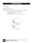
2. Remove the top cover of the CC1. Refer to Figure 36.
a.
Remove the 10 screws that hold the top cover in place.
b.
Tilt the top cover up at a slight angle, as indicated by the dotted line in the drawing, and then pull the cover backwards to remove the
cover from the front edge of the CC1 chassis.
Figure 36. Removing the CC1 Top Cover
3. Set the W1 interrupt (IRQ) and W2 address select jumpers on the SER card. Refer to Figure 37.
Note that the jumper settings vary, depending on the ISA slot in which the SER card is to be installed. Refer to the following tables for a list of
SER card jumper assignments.
Table F. SER Card Jumper Assignments for a CM9700-CC1 System Control
ISA Slot Number
W1 IRQ Setting
W2 Address Setting
1
IRQ 10
Pins 1 to 2 and 3 to 4
2
IRQ 11
Pins 1 to 2 only
3
IRQ 12
Pins 3 to 4 only
4
IRQ 5
No jumpers
Table G. SER Card Jumper Assignments for a CM9700-NW1 Network Interface Unit
ISA Slot Number
W1 IRQ Setting
W2 Address Setting
1
IRQ 10
Pins 1 to 2 and 3 to 4
2
IRQ 11
Pins 1 to 2 only
3
IRQ 12
Pins 3 to 4 only
NOTE: For a CM9700-NW1, the default configuration is one SER card. A maximum of three SER cards can be installed in a CM9700-NW1.
46
C1555M-G (12/07)