1
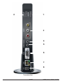
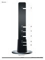
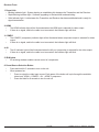
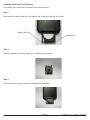
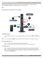
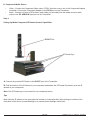
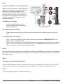
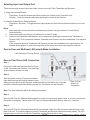
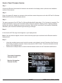
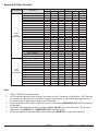
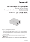
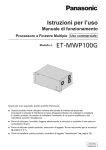
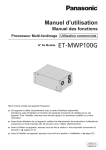
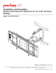
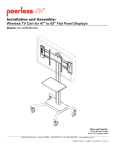
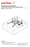
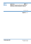
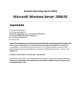
User Manual and Installation Guide
Pro Wireless Multimedia Kit
Models:
HDS200
HDS200-2
HDS200-3
HDS200-4
®
R E ADY
ISSUED: 07-24-12 SHEET #: 180-9023-1
Contents
Safety Precautions ...........................................................................................................................................4
Proper Care and Safety ....................................................................................................................................4
Unit Care Recommendations ..........................................................................................................................4
Introduction.......................................................................................................................................................5
Features .........................................................................................................................................................5
Package Contents ..........................................................................................................................................5
Product Specifications.....................................................................................................................................6
Video Format Supported ................................................................................................................................7
Audio Format Supported ................................................................................................................................7
Wireless Connection ......................................................................................................................................7
WiFi Channel Frequencies .............................................................................................................................7
Transmitter .....................................................................................................................................................8
Receiver .......................................................................................................................................................12
Remote Control ............................................................................................................................................16
Installation and Operation .............................................................................................................................19
Selecting Input and Output Port ..................................................................................................................23
Peer-to-Peer and Multicast LAN (wired) Mode Installation ..........................................................................23
Peer-to-Peer Direct LAN Connection ...........................................................................................................23
LAN Connection Through Router (LAN One-to-One) ...................................................................................24
Configuring for LAN Through Router (LAN One-to-One) .............................................................................24
Indicator Lights Decoded ..............................................................................................................................25
IR Flasher .....................................................................................................................................................26
IR Extender ..................................................................................................................................................26
Product Modes .............................................................................................................................................26
Peer-To-Peer Modes ....................................................................................................................................26
Multicast Modes ...........................................................................................................................................27
LAN - Wired Connection Mode .....................................................................................................................27
FAQs ................................................................................................................................................................28
Appendix .........................................................................................................................................................30
Warranty ..........................................................................................................................................................34
Contact Information .......................................................................................................................................35
3 of 36
ISSUED: 07-24-12 SHEET #: 180-9023-1
Safety Precautions
Keep the product out of reach of
children.
Keep the product away from external
heat sources such as heaters or
stoves.
If there is any unusual sound, smoke
or odor coming from the product,
immediately unplug the product and
call Peerless-AV Customer Care at
1-800-865-2112.
Keep the battery of remote control out
of reach of children.
Do not attempt to open the outer case
of the Transmitter or Receiver. Doing
so will void the product warranty.
Keep the remote control away from
humidity and/or liquids.
Do not insert foreign objects into the
unit.
Do not place the unit on an unstable
surface or in a poorly ventilated area.
Make sure to plug the AC power
adapters firmly into wall outlets.
Do not use the unit near any flammable
substances or combustible sprays.
If any part of the AC power adapter
looks damaged, do not use the product
and immediately call Peerless-AV
Customer Care at 1-800-865-2112.
Keep the product unplugged if unused
for an extended period of time.
Proper Care and Safety
Please read this manual before using the product.
Unit Care Recommendations
•
Unit can be placed vertically (preferred) or horizontally.
•
To clean, use a soft, dry cloth only. Do not use water or other cleaning products as they
may cause electrical failure or damage the surface of the product.
4 of 36
ISSUED: 07-24-12 SHEET #: 180-9023-1
Introduction
HD Flow Pro Wireless Multimedia Kit provides Full HD 1080p signal transfer, including 3D signal*, without the
hassle of running cables. Create brilliant HD quality multimedia for signage, presentations, or entertainment in
any location,completely un-tethered to your source device!
By simply connecting the Transmitter to a multimedia device such as a computer, set-top box, or Blu-ray™
player and connecting the Receiver to a display device, instant real-time high definition digital audio and video
can be placed into in any commercial or residential setting. HD Flow Pro Wireless Multimedia Kit transmits
through walls and floors to allow the components to be neatly tucked away in an AV rack or media cabinet,
and is the ideal solution for quick and easy installation where running cable is cost prohibitive or simply not an
option.
* Works with passive 3D signals
Features
•
•
•
•
•
•
•
•
Low latency: ≤ 30ms.
Supports both digital (HDMI) and analog (Component, Composite) video/audio.
Supports Wireless or Wired connection - IEEE 802.11n 5 GHz WiFi, LAN connection.
Two internal antennas (supporting MIMO).
HDCP v1.1 compliant.
Supports both DTV & VESA standards: DTV: 1920x1080i60/p60, 1280x720p60, 720x480i60/p60,
VESA : WSXGA+(1680x1050), SXGA(1280x1024), WXGA(1280x800), XGA(1024x768),
SVGA(800x600), VGA(640x480).
Supports passive 3D content.
Plug and play setup requires no software programming.
Package Contents
Ensure that the following items are present in the package. If any items are missing or damaged, please call
Peerless-AV Customer Care at 1-800-865-2112 (available 7:00am - 7:00pm CST Monday - Friday).
Transmitter
Receiver
Component
Adapter
Stand (2)
Remote Control
User Manual and Installation Guide
Pro Wireless Multimedia Kit
Models:
HDS200
HDS200-2
HDS200-3
HDS200-4
®
R E ADY
ISSUED: 06-12-12 SHEET #: 180-9023-1
Battery
IR-Extender
AC Adapter (2)
Quick Start Guide
PRO WIRELESS MULTIMEDIA KIT
Manual
®
R E ADY
2
Minutes
Model No. HDS200 (-2, -3, -4)
What’s in the Box
1 x Transmitter
1 x Receiver
2 x Stand
1 x Remote Control
1 x IR Flasher
IR-Flasher
Step 7 While turning on the display device the HD Flow Pro Wireless Multimedia units will be going through the startup process. This process may
take up to two minutes to complete. The Power/Link indicator lights on the Transmitter and the Receiver will be flashing at first. Flashing indicates
that the units are establishing a secure connection. Wait until the connection is successfully established, indicated by the Power/Link indicator
light becoming solid.
1 x IR Extender
1 x Component Adaptor
2 x Power Adapter
1 x Quick Start Guide
1 x Users Manual
Power/Source
Selection Button
Installation and Setup
Tip The IR window
may be easier to
locate with a direct
light shining on
sections of the
front panel of the
component device.
A small flashlight
works well.
Step 1 Connect the Transmitter to the source devices
(Blu-ray ™ Disc player, set top box, gaming console, etc.).
Step 8 Select the output that connects the Receiver to the display using
the Power/Source Selection Button or the provided remote control.
The output indicator light will become solid and the HD Flow logo will
appear on the display device.
Step 9 Turn on the desired source device that is connected to
the Transmitter.
Power/Source
Selection Button
Step 2 Connect the provided IR Flasher to the IR-OUT port on the Transmitter.
Find the location of the IR window on your component device and adhere the
IR Flasher eye directly over the IR window on your component device.
NOTE: One IR Flasher eye is to be used for one component device.
Step 10 Select the desired source or device input on the Transmitter
using the Power/Source Selection Button on the remote control.
Step 11 Play the source device content and enjoy up to Full HD 1080p
wireless entertainment experience.
Troubleshooting Tips
Transmitter and/or Receiver Indicator Lights are all Blinking:
t The HD Flow Pro units are establishing a connection. It can take
up to two minutes for the HD Flow Pro units to establish a complete
connection. If after two minutes have passed and the units have not
established a connection, unplug the power cable, wait 30 seconds
and reconnect the power supply to the units.
Tip Repeat Steps
teps
3-11 to
more t
Receiv
(HDS20
HDS20
HDS20
Step 3
to the Receiver.
Step 4 I
rovided IR Extender in to
the IR-IN port on the Receiver and adhering the other end of the IR Extender
to a vertical surface near the output device. Ensure that the IR Extender is in
a line of sight to the remote control that controls your source devices.
NOTE: For Multicast models, receivers two, three and four do not come with an IR Extender. Additional IR Extenders
(HDS-IRE) can be purchased separately; visit peerless-av.com for more information.
Transmitter or Receiver Power Indicator Light is OFF:
t Check and verify the power supply connection.
Transmitter Input Indicator Light Blinks:
t Make sure that your source device is turned ON and the cable
is properly connected.
Verify that the Transmitter is set to the appropriate input port.
Check the resolution from your source device. This may need to
be changed to a resolution supported by the HD Flow Pro Wireless
Multimedia Kit. Reference the Resolution Chart in the HD Flow
Manual for compatibility. Reference your source devices’ manual
for instruction on changing the output resolution.
t
t
S
1. Plug in the power adapter for the Transmitter and the Receiver to nearby
available power outlets.
2. Plug in the power adapter end to the Transmitter and then to the Receiver.
3. The units will automatically turn-on. The average power-on/sync time
is approximately two minutes.
Step 6 Turn on your display device (TV, monitor, projector, etc.).
Receiver Power Indicator Light Blinks:
t Verify that the HD Flow Pro Transmitter and Receiver are within
the recommended range of 131 feet. Physical obstructions such as
walls, floors and ceilings between the Transmitter and Receiver may
decrease the strength of the connection signal and reduce the overall
transmission range.
t
Check the media source resolution. The display device must be able
to support the resolution of the media source that is being streamed.
Utilizing the INFO button will allow you to see the resolution data that
the display device supports. If the display device supports the highest
resolution of 720p but the source device is outputting 1080p content,
the content needs to be down-scaled to the maximum resolution of the
display device, in this case 720p.
Receiver Output Indicator Light Blinks:
t Make sure that your display device, source device and the HD Flow Pro units
are all turned ON and the Receiver is properly connected to the output device.
t Verify that the Receiver is set to the appropriate output port.
t Check the resolution setting of your source device. This may need to be
changed to a resolution supported by the HD Flow Pro unit. Reference
the Resolution Chart in the HD Flow Pro Manual for compatibility.
Reference your source devices’ manual for instruction on changing
the output resolution.
If the above troubleshooting tips do not resolve the issues for a unicast setup,
please reference the Factory Reset Section of the HD Flow Pro Manual. For a
multicast system configuration, please contact Peerless-AV Customer Care at
800-856-2112 for further instruction.
If a connection has been established and the HD Flow logo can be seen
on the display device, but content is not playing:
t Make sure that the input/output cables are properly connected.
t Verify that the Transmitter is set to the appropriate input port.
© 2012 Peerless Industries, Inc. Peerless-AV™ is a trademark of Peerless Industries, Inc. All rights reserved.
HD Flow™ is a trademark of I Do It, LTD. Other parties’ marks are the property of their respective owners. hdflow.com
Warning Do not place the HD Flow
Pro units near other devices that
emit excessive amounts of heat.
Increased temperatures may
cause the HD Flow Pro Transmitter
or Receiver unit to malfunction
or stop working.
Quick Start Guide for HD Flow Pro Wireless Multimedia Kit - LIT-0906
Quick Start Guide
5 of 36
ISSUED: 07-24-12 SHEET #: 180-9023-1
Product Specifications
Video Input (Transmitter)
Video Output (Receiver)
Encoding
Wireless Connection
Wired Connection
LAN
USB
Audio Input
Audio Output
Video Resolution
Streaming Latency
Frequency
LAN Connection
Range
Broadcast
Security
Antenna Type
IR Flasher
IR Extender
Color
Power
HDS200 Models
2 x HDMI up to 1080p (60Hz)
1 x Composite
1 x YPbPr Component
1 x HDMI up to 1080p (60Hz)
1 x Composite
1 x YPbPr Component
H.264 Baseline Profile with Level 4.2
HDCP compliant
Supporting IEEE 802.11n: OFDM
RJ-45 LAN Port
Direct Connection (LAN Cable)
1 x LAN Port (Transmitter and Receiver)
10/100 Base
1 x USB Type A Female (Receiver)
1 x 3.5mm Audio Jack, 1 Stereo RCA Audio Jack (Transmitter)
1 x 3.5mm Audio Jack, 1 Stereo RCA Audio Jack (Receiver)
480i/p, 720p, 1080i/p (24/30/60fps)
< 30ms
5.15 - 5.25GHz
10/100 Base
131ft (40m) maxium
1 Transmitter up to 4 Receivers*
802.1x, 802.11i, WPA2, WPA and WEP 64/128 TKIP AES
2 x Internal Antenna (Transmitter and Receiver)
MIMO Interface
3 IR Flashers
IR-Extender
Black
Voltage: 12VDC
Amps: 2A
Consumption: 12V 2A
*Requires additional Receiver units
6 of 36
ISSUED: 07-24-12 SHEET #: 180-9023-1
Video Format Supported
•
Digital Video
º
HDMI - Up to 1080p @ 24Hz, 25Hz, 30Hz, 50Hz, 60Hz
•
Analog Video
º
Composite – 480i @ 60Hz, 70Hz, 85Hz
º
Component – 1080i @ 50Hz, 60Hz, 720p @ 50Hz, 60Hz
º
VGA – Up to 1920x1080 @ 50Hz, 60Hz
Audio Format Supported
•
•
•
Analog
Digital
Receiver outputs stereo audio
Wireless Connection
•
•
Peer-to-Peer Mode
Multicast Wireless Mode
WiFi Channel Frequencies
•
•
Channel 1: 5.19GHz (WiFi Ch 38)
Channel 2: 5.23GHz (WiFi Ch 46)
Note: WiFi Channels are only active when using Wireless Peer-to-Peer or Multicast modes. The Transmitter
and Receiver have the ability to operate on two WiFi Channels. The default channel is Channel 1, if there is
interference issues on Channel 1 a change to Channel 2 will eliminate most of these issues.
7 of 36
ISSUED: 07-24-12 SHEET #: 180-9023-1
Transmitter
1
2
3
4
5
6
7
Transmitter Front
8 of 36
ISSUED: 07-24-12 SHEET #: 180-9023-1
Transmitter Front
1. Power/Link Indicator Light
• Blinking indicator light - System booting or establishing link between the Transmitter and the Receiver.
• Quick blinking indicator light - Software upgrading or wireless/LAN mode switching.
• Solid indicator light - Link between the Transmitter and Receiver has been established and is ready for
signal transmission.
2. HDMI 1
•
The HDMI 1 indicator light will be illuminated when the HDMI 1 port is selected for video input.
•
If there is no signal, and/or the cable is not connected, the indicator light will blink.
3. HDMI 2
•
The HDMI 2 indicator light will be illuminated when the HDMI2 port is selected for video input.
•
If there is no signal, and/or the cable is not connected, the indicator light will blink.
4. PC
•
The PC indicator light will be illuminated when the PC In port is selected for video input.
•
If there is no signal, and/or the cable is not connected, the indicator light will blink.
5. AV
•
The AV indicator light will be illuminated when the AV In port (Composite) is selected for the video input.
•
If there is no signal, and/or the cable is not connected, the indicator light will blink.
6. IR Window
•
IR receiving window enables remote control of components.
7. Power/Source Selection Button
•
Press and hold for 3 seconds to turn on the unit.
•
When powered on:
º
Press to select the video input source. Each press of the button will cycle through the available
video input "HDMI1→ HDMI2→ PC→ AV →HDMI1" in sequence.
º
Press and hold for 8 seconds to turn the unit off.
9 of 36
ISSUED: 07-24-12 SHEET #: 180-9023-1
2
1
3
4
5
6
7
8
Transmitter Back
10 of 36
ISSUED: 07-24-12 SHEET #: 180-9023-1
Transmitter Back
1. HDMI 1 IN
•
HDMI1 input port
2. HDMI 2 IN
•
HDMI2 input port
3. AV-IN
•
Composite input port
4. IR-OUT
•
Connects IR Flasher to the Transmitter for remote control of external devices which are connected to the
Transmitter (i.e. Blu-Ray player, DVD, STB, etc).
5. PC AUDIO-IN *
•
Stereo audio input port
6. PC-IN (VGA)**
•
Supports component input with included Component Adaptor
7. LAN
•
LAN connection is used for the following:
º
Direct connection to LAN cable for LAN installations.
º
Direct connection to PC for system configuration settings.
8. DC
•
DC power input
* For the audio part of a component media source, use the PC Audio input port with a 3.5mm to RCA cable
(not included).
** If using the PC Video input port for component (YPbPr) media source, use the included component to VGA
adapter.
11 of 36
ISSUED: 07-24-12 SHEET #: 180-9023-1
Receiver
1
2
3
4
5
6
Receiver Front
12 of 36
ISSUED: 07-24-12 SHEET #: 180-9023-1
Receiver Front
1. Power/Link
• Blinking indicator light - System booting or establishing link between the Transmitter and the Receiver.
• Rapid blinking indicator light - Software upgrading or wireless/LAN mode switching.
• Solid indicator light - Link between the Transmitter and Receiver has been established and is ready for
signal transmission.
2. HDMI
•
The HDMI indicator light will be illuminated when the HDMI port is selected for video output.
•
If there is no signal, and/or the cable is not connected, the indicator light will blink.
3. COMPO
•
The COMPO (component) indicator light will be illuminated when component output is selected for video
output.
•
If there is no signal, and/or the cable is not connected, the indicator light will blink.
4. AV
•
The AV indicator light will be illuminated when the AV port (composite) is selected for the video output.
•
If there is no signal, and/or the cable is not connected, the indicator light will blink.
5. IR Window
•
IR receiving window enables remote control of components.
6. Power/Source Selection Button
•
Press and hold for 3 seconds to turn on the unit.
•
When powered on:
º
Press to select the video input source. Each press of the button will cycle through the available
video input "HDMI→ COMPO→ AV →HDMI" in sequence.
º
Press and hold for 8 seconds to turn the unit off.
13 of 36
ISSUED: 07-24-12 SHEET #: 180-9023-1
1
2
3
4
5
6
7
8
Receiver Back
14 of 36
ISSUED: 07-24-12 SHEET #: 180-9023-1
Receiver Back
1. HDMI-OUT
•
HDMI output port
2. AV-OUT
•
Composite output port
3. IR-IN
•
Connects the IR Extender in order to extend IR reception range.
4. AUDIO-OUT*
•
Stereo audio output port
5. COMPONENT-OUT*
6. USB
•
USB port is used for firmware upgrades only.
7. LAN
•
LAN connection port is used for the following:
º
Direct connection for LAN installations.
º
Direct connection to PC for system configuration settings.
8. DC
•
DC power input
* For the audio part of a component media source, use the PC Audio Input port with a 3.5mm-to-RCA cable
(not included).
15 of 36
ISSUED: 07-24-12 SHEET #: 180-9023-1
Remote Control
1
2
4
5
3
8
6
7
1. POWER Button - Turns the Transmitter and Receiver power ON/OFF.
•
ON: If the Transmitter and Receiver are powered off and the Power/Link Indicator Light is on, press
the power button pointed at either unit to turn on both unit's at the same time (this will take about 30
seconds).
•
ON: If the Transmitter and Receiver are powered off and the Power/Link Indicator Light is off, each unit
will need to be turned on separately. Point the remote at each unit's IR Input port and press the power
button to turn on (this will take about 1 minute and 30 seconds).
•
OFF: If the Transmitter and Receiver are powered on and the Power/Link Indicator Light is on, press the
power button to turn off both units at the same time to put the system in Standby mode. The Power/Link
Indicator Light will remain on.
•
OFF: If the Transmitter and Receiver are powered on and the Power/Link Indicator Light is on, press
and hold the power button for 8 seconds. Both Transmitter and Receiver will be turned off at the same
time. The Power/Link Indicator Light will turn off.
Note: If the Transmitter and Receiver are powered on with the Power/Link Indicator Light flashing, both units
will need to be powered off individually.
2. INFO* - Displays the following information on the screen for:
•
•
Transmitter ** - WiFi Channel, Firmware Version, Audio/Video Input, and Source Resolution.
Receiver - Connection, Firmware Version, Video Output, Display Resolution, WiFi Reception Strength
1/5 to 5/5 (where 1/5 is the weakest signal and 5/5 is the strongest signal).
* Displayed information will disappear automatically after 10 seconds.
** The Transmitter unit’s information will only be displayed if the connection between the Transmitter unit and
Receiver has been established.
16 of 36
ISSUED: 07-24-12 SHEET #: 180-9023-1
3. VIDEO OUT (Receiver) - Selects the Audio/Video output port of the Receiver.
•
•
•
HDMI - Selects HDMI as the Audio/Video output.
Component - Selects Component as the Audio/Video output.
AV - Selects AV as the Audio/Video output.
Note: Remote must be pointing at the Receiver directly to control its output settings. This may also be
accomplished without the use of the remote control by toggling between outputs via the Power/Source Selection
Button.
4. VIDEO IN (Transmitter) - Selects the Video input port of the Transmitter.
•
•
•
•
HDMI1 - Selects HDMI1 as the Audio/Video input.
HDMI2 - Selects HDMI2 as the Audio/Video input.
PC - Selects VGA/Component as the Video input.
AV - Selects Composite as the Video input.
5. AUDIO IN (Transmitter) - Selects the Audio input port of the Transmitter.
•
•
•
•
HDMI1 - Selects HDMI1 as the audio input.
HDMI2 - Selects HDMI2 as the audio input.
PC - Selects PC audio-in as audio input.
AV - Selects Composite audio-in as the audio input.
Notes:
1. By default, when a video input is selected the audio will automatically be switched to the same input
where audio is available.
2. Independent audio switching is only allowed for AV Audio and PC Audio.
6. LAN* (Red) - Selects LAN (wired) mode.
7. WiFi CH1** (Green) - Selects WiFi (Wireless) mode, Ch1.
8. WiFi CH2** (Yellow) - Selects WiFi (Wireless) mode, Ch2.
* Press and hold the LAN button for approximately 6 seconds to change the connection setting to Wired Mode.
** To change WiFi channels press and hold the desired WiFi channel button for approximately 6 seconds or until
the Link Indicator Light starts blinking.
Note: If the WiFi channel is changed while the wireless connection between the Transmitter and Receiver is
active, noted by a solid Link Indicator Light, the WiFi frequency of the Transmitter and the Receiver will be
changed simultaneously. If the WiFi channel is changed while the connection between the Transmitter and the
Receiver is not established, noted by a flashing Link Indicator Light, ONLY the unit that receives the IR signal
will change WiFi frequencies. For proper operation both Transmitter and Receiver need to be on the same WiFi
channel.
17 of 36
ISSUED: 07-24-12 SHEET #: 180-9023-1
Installing the Remote Control Battery
The battery slip is located on the bottom of the remote control.
Step 1
Push the tab, located on the left of the battery slip, to the right and pull out the slip.
Battery Slip Tab
Battery Slip
Step 2
Place the battery into the slip, positive (+) end facing up as shown.
Step 3
Place the slip back into the remote to complete the installation.
18 of 36
ISSUED: 07-24-12 SHEET #: 180-9023-1
Installation and Operation
Before starting the installation, please ensure that all source components (Blu-ray player, cable box,
etc.) and the display equipment (TV, display, projector, etc.) are turned off.
Step 1
Connecting Source Components To The Transmitter
B
A
D
C
D
A. HDMI Media Source
•
Connect HDMI cable from the source components output to the Transmitter's HDMI1 or HDMI2 input
port.
Note: It is recommended that HDMI1 input port be used if only one HDMI source component is present.
B. Composite Media Source
•
•
Video – Connect “yellow” composite video RCA post to yellow port.
Audio – Connect “red and white” composite audio RCA posts to the red and white ports.
C. VGA Media Source
•
•
Video - Connect the VGA cable from the media source’s VGA output to the Transmitter’s VGA input.
Audio - A 3.5mm stereo audio cable is required (not included) to transmit audio when using this
input. Connect the 3.5mm stereo audio cable from the VGA source component’s audio output to the
Transmitter's PC AUDIO-IN port.
19 of 36
ISSUED: 07-24-12 SHEET #: 180-9023-1
D. Component Media Source
•
•
Video – Connect the Component Video output (YPbPr) from the source, into to the Component Adapter
(included). Connect the Component Adapter to the PC-IN port on the Transmitter.
Audio - Connect a 3.5mm-to-RCA stereo audio cable (not included) from the media source’s audio
output to the PC AUDIO-IN input port on the Transmitter.
Step 2
Setting Up Media Component IR Remote Control Capabilities
IR-OUT Port
IR Flasher Eye
A. Connect the provided IR Flasher to the IR-OUT port of the Transmitter.
B. Find the location of the IR widow on your component and adhere the IR Flasher Eye directly over the IR
window of your component.
Note: One IR Flasher eye is to be used for one component device.
Tips
Most often the IR window on the source device is easier to locate with direct light shining on sections of the
front panel of the device (a small flashlight or a camera phone flashlight works well).
20 of 36
ISSUED: 07-24-12 SHEET #: 180-9023-1
Step 3
Connecting the Receiver to the Display Device
Note: Connect the Receiver to the display device
using the port with the high resolution capability,
HDMI port is preferred. Regardless of the
number of analog or digital sources connected
to the Transmitter, only one port is required to
be connected to the display. Be sure the source
resolution matches with the display device's
resolution capabilities.
A. HDMI Output to Display
•
Connect the HDMI cable from the
Receiver's HDMI output to the display
device's HDMI input.
B. Composite Output to Display
•
Connect the composite RCA cable from the Receiver's AV output to the display device's composite
input.
C. Component Output to Display
•
•
Video - Connect the component video (YPbPr) cable from the Receiver's COMPONENT-OUT to the
displays device's component input.
Audio - A 3.5mm-to-RCA stereo audio cable is required (not included) to transmit audio when using this
input. Connect the 3.5mm end of the cable to the Receiver's AUDIO-OUT port, then connect the RCA
side of the cable to the RCA ports on the display decive.
Step 4
Install the IR Extender by plugging in the provided IR Extender into the IR-IN port on the Receiver. (IR Extender
use is optional. Use the IR Extender when the Receiver is out of sight or to extend the range of the Receiver's
IR reception range.)
Step 5
Powering-up the HD Flow Multimedia Kit
Plug in the power adapters for the Transmitter and the Receiver to available power outlets. Plug in the other
end of the power cable to the Transmitter and then to the Receiver. The units will automatically turn on.
Step 6
Turn on your display device (TV, monitor, projector, etc.)
21 of 36
ISSUED: 07-24-12 SHEET #: 180-9023-1
While turning on the display device, the HD Flow Pro Wireless Multimedia Kit will be going through the start
up process. The process takes about 1.5 to 2 minutes to complete. The Power/Link Indicator Light on the
Transmitter and the Receiver should be flashing at first. Flashing indicates that that the units are establishing
a secure connection. Wait until the connection is successfully established, indicated by a solid Power/Link
Indicator Light.
Step 7
Select the output that the Receiver is connected to the display device with. At this time the output indicator light
will become solid and the HD Flow logo will appear on the display device.
Step 8
Turn on the desired media source device that is connected to the Transmitter.
Step 9
Select the desired media source device input on the Transmitter.
Step 10
Play the source device media content and enjoy up to Full HD 1080p wireless entertainment experience.
Tips
If the Transmitter and Receiver are not establishing a connection:
a. Ensure that both the Transmitter and Receiver are on the same WiFi Channel.
b. If the units are not connecting after trying (a), it is recommended to unplug the power to both units,
let it rest for 30 seconds and then plug them back in. This will power cycle the units and allow them to
reboot themselves.
c. If the above two tips do not assist, please reference the Factory Reset section of this manual.
(Appendix)
If the connection has been established and the HD Flow logo can be seen on the display device, but content is
not playing when initiated:
a. Ensure that cables are properly connected.
b. Ensure the Transmitter is set to the proper input port and that the Receiver is set to the proper
output port.
c. Ensure that the display device is set to the proper input.
d. The display device needs to be able to support the resolution of the media source that is being
streamed. Utilizing the INFO button, while connected via HDMI, will allow you to see the EDID
resolution data that the display device accepts. (Example - If the display device supports the highest
resolution of 720p but the source device is outputting 1080p content, the content needs to be
downscaled to the maximum resolution of the display device, in this case 720p).
22 of 36
ISSUED: 07-24-12 SHEET #: 180-9023-1
Selecting Input and Output Port
There are two ways to select input and output sources on the HD Flow Transmitter and Receiver:
1. Using the provided Remote
•
Transmitter - Press the desired input while pointing the remote at the Transmitter unit.
•
Receiver - Press the desired output while pointing the remote at the Receiver.
2. Using the Power/Source Selection Button
•
Transmitter / Receiver - To toggle between inputs press the Power/Source Selection Button on the unit
itself.
Notes:
1. Audio and video sources will switch simultaneously whether using the remote or Power/Source
Selection Button.
2. Independent audio switching is only allowed for AV and PC audio.
3. Inputs on the Transmitter and Receiver can be switched by pointing the remote at the Transmitter or
Receiver ONLY if the connection between Transmitter and Receiver has been established, Link Indicator
Light on.
If the connection between Transmitter and Receiver has not been established, the inputs need to be
selected at the location of each unit using either of the above input and output selection methods.
Peer-to-Peer and Multicast LAN (wired) Mode Installation
LAN Connection Through Router
Peer-to-Peer Direct LAN Connection
Step 1
Connect the LAN cable between the RJ45 jack
on the Transmitter and Receiver. The green light
at the connector will turn on solid.
Step 2
With the system running (Power/Link Indicator
Light solid and input and output Indicator Lights
solid), point the remote at the Receiver, press and hold the LAN button for 5 seconds
until all the indicator lights start flashing on both the Transmitter and the Receiver.
Peer-To-Peer
Direct Lan
Connection
Note: The video and audio will be lost during this process.
Step 3
Allow the HD Flow Pro Wireless Multimedia Kit to re-start. Do not remove power, reset, or use the remote while
the system is restarting. Restart of the HD Flow Pro Wireless Multimedia Kit may take up to 2 minutes.
Step 4
Once the HD Flow Pro Wireless Multimedia Kit has restarted, check the LAN connection indicator light on the
back of the unit. The indicator lights on both the Transmitter and Receiver should be blinking rapidly. The WiFi
indicator lights on the front of both the Transmitter and the Receiver will be solid.
23 of 36
ISSUED: 07-24-12 SHEET #: 180-9023-1
Notes:
1. We recommend that you disconnect and then re-connect the LAN cable to ensure LAN operation. Once
video and audio come back up, the process is complete.
2. To return the units back to WiFi mode press the WiFi Channel 1 button for 5 seconds in front of the
Receiver until all the indicator lights start flashing on both the Transmitter and the Receiver. The video
and audio will be lost during this process.
3. LAN setting can be changed to a single unit independently by following the above instruction with only
the Transmitter or Receiver turned on.
LAN Connection Through Router (LAN One-to-One)
When connecting the HD Flow Pro Wireless Multimedia Kit through a router, the Ethernet IP addresses of
the Transmitter and Receiver need to match the domain of the router (i.e. 192.168.x.x). Once the Ethernet IP
addresses are in the same domain, the indicator lights located at the top of the unit will become solid, signifying
connection.
Configuring for LAN Through Router (LAN One-to-One)
Note: Networking experience is recommended for configuring LAN through router settings.
Transmitter and Receiver need to be configured to LAN setting individually using the guide below:
Step 1
Configure your computer's Ethernet static IP settings to the following:
IP Address: 192.168.0.157
Subnet Mask: 255.255.255.0
Default Gateway: 192.168.0.1
Step 2
Plug in the HD Flow Pro Wireless Multimedia Kit and ensure it has fully started up (Power/Link Indicator Light
and one Input Indicator light will be blinking).
Step 3
Connect one end of the RJ45 cable to the computer and the other end of the RJ45 cable to the Transmitter or
Receiver.
Step 4
Open your preferred browser. In the URL enter 192.168.0.151 for Transmitter, 192.168.0.152 for Receiver and
press enter. You will be taken to the programming page.
Notes:
1. The Transmitter Ethernet IP address is always 192.168.0.151, the IP address of a new Receiver will
always be 192.168.0.152. (Multiple Receivers can be configured on a LAN system, each additional
Receiver needs to be assigned an Ethernet IP address one greater than 192.168.0.152. Example
Receiver 1: 192.168.0.152, Receiver 2: 192.168.0.153, Receiver 3: 192.168.0.154, Receiver 4:
192.168.0.155, and so on).
2. Receivers on the same LAN network cannot have identical Ethernet IP addresses.
24 of 36
ISSUED: 07-24-12 SHEET #: 180-9023-1
Step 5
Under the heading “Streaming I/F” use the pull down menu to change WiFi to LAN.
Step 6
Enter the proper IP address, for the unit being set up, based on the network's domain.
Step 7
Once all the settings have been entered click the Submit button at the bottom of the form. Keep clicking on the
Submit button until you see confirmation "System configurations are changed", as below:
Step 8
After submitting the information and receiving confirmation it is MANDATORY to click on Save Changes,
located in the left-hand navigation bar to ensure that your programming will be saved. Once clicking on Save
Changes, you will be prompted to save your system configurations. Confirm that you would like to save them
by clicking the Save button. You will be prompted again to make sure you want to save these changes. Confirm
that you would like to save them by clicking the Save button again.
Indicator Lights Decoded
Transmitter/Receiver
•
Power/Link Indicator Light
º
Rapid Flashing – Switching from Wireless to LAN or from LAN to Wireless connection or
performing firmware update.
º
Flashing – Units are booting and establishing a secure connection for AV transfer.
º
Solid – Successful connection has been established between Transmitter and Receiver(s).
25 of 36
ISSUED: 07-24-12 SHEET #: 180-9023-1
Transmitter
•
HDMI1, HDMI2, PC, AV – The indicator light will be lit to indicate the input that is currently selected. If
the selected input does not have a connection or the signal from the media source is not present, the
selected input Indicator Light will be flashing.
Receiver
•
HDMI, COMPO, AV - The indicator light will be solid for the selected port as long as the output cable is
present and connected to the output device. If no output device is detected by the selected output port,
the indicator light will be flashing.
IR Flasher
IR Flashers are provided to allow for control of up to three source devices using the device’s original remote
control at the Receiver location. The IR Flasher is connected to the Transmitter and its three eyes are adhered
to the media source devices' IR window (See Setting Up Media Component IR Remote Control Capabilities
in the Installation and Operation section of this manual).
IR Extender
The IR Extender provided extends the range of the IR on the Receiver and support placement of the Receiver
out of sight. (See Connecting The Display Device to the Receiver in the Installation and Operation section
of this manual).
Product Modes
HD Flow Pro Wireless Multimedia Kits have the capability to stream from one Transmitter to one Receiver or
from one Transmitter to up to four Receivers.
Model
Capability
Mode
HDS200: HD Flow Pro Wireless Multimedia Kit: streams to one display devices
Peer-to-Peer Wireless
HDS200-2: HD Flow Pro Wireless Multimedia Kit: streams to two display devices Multicast Wireless
HDS200-3: HD Flow Pro Wireless Multimedia Kit: streams to three display devices Multicast Wireless
HDS200-4: HD Flow Pro Wireless Multimedia Kit: streams to four display devices Multicast Wireless
Note: Maximum of four (4) Receivers can be paired to one Transmitter when using Multicast Wireless mode.
Peer-To-Peer Modes
Peer-To-Peer Wireless Mode
Peer-to-Peer Wireless Mode is a pre-configured setting that enables one Transmitter to stream AV media to one
Receiver. HDS200 model HD Flow Pro Wireless Multimedia Kit comes pre-configured for Peer-to-Peer Wireless
mode.
Peer-To-Peer LAN (wired) Mode
Peer-to-Peer LAN (wired) Mode is an available configuration for applications where wireless signal transfer
is not desired, allowed or surpasses wireless distance limitations. This mode allows the Transmitter to be
connected directly to the Receiver using an Ethernet cable to transmit AV signal. Wired connection mode
requires a CAT5e/6 cable to be connected to the LAN ports between the Transmitter and Receiver. Please visit
http://www.hdflow.com/Tech-Support for step-by-step LAN programming instructions.
26 of 36
ISSUED: 07-24-12 SHEET #: 180-9023-1
Note: Peer-to-Peer units can be configured to multicast mode using the USB Multicast Set-Up Method or LAN
Multicast Set-Up Method. Additional Receivers (HDS200-R) are required and sold separately. Please visit
http://www.hdflow.com/Tech-Support for programming instructions.
Multicast Modes
Multicast Wireless Mode
Multicast Wireless Mode is a pre-configured setting that enables the Transmitter to stream AV media from
one Transmitter to up to four Receivers. All multicast systems come preconfigured to wirelessly stream to the
specified number of Receivers.
Available Multicast Models
Model
Capability
HDS200-2:
HD Flow Pro Wireless Multimedia Kit: streams to two display devices
HDS200-3:
HD Flow Pro Wireless Multimedia Kit: streams to three display devices
HDS200-4:
HD Flow Pro Wireless Multimedia Kit: streams to four display devices
Mode
Multicast Wireless
Multicast Wireless
Multicast Wireless
Multicast LAN (wired) Mode (Advanced Settings)
Multicast LAN (wired) Mode is an available configuration for applications where wireless signal transfer is
not desired, allowed or surpasses wireless distance limitations. This mode allows for the Transmitter to be
configured to an existing LAN to transmit AV signal to multiple Receivers. Please visit http://www.hdflow.com/
Tech-Support for step-by-step LAN programming instructions.
Note: Additional Receivers (HDS200-R, sold separately) are required when adding on to a peer-to-peer system.
Converting a Peer-to-Peer Wireless HD Flow Multimedia Kit to a Multicast Wireless
Multimedia Kit
After the purchase of additional Receiver(s), part number HDS200-R, use the following instructions to add the
Receiver(s) to the current system.
USB Multicast Set-Up Method
To set up the HD Flow Pro Multimedia Kit as a multicast system that transmits to 2, 3 or 4 Receivers using the
USB Multicast Set-Up Method please visit http://www.hdflow.com/Tech-Support to view the instructional
video.
LAN Multicast Set-Up Method (Advanced Settings)
To set up the HD Flow Pro Wireless Multimedia Kit as a multicast system that transmits to 2, 3 or 4 Receivers
using the LAN Configuration Method please reference the instruction manual that comes with the HDS200-R or
visit http://www.hdflow.com/Tech-Support to download instructions.
LAN - Wired Connection Mode
The wired connection mode requires a CAT5e/6 cable to be connected to the LAN ports between the
Transmitter and Receiver. HD Flow Pro Wireless Multimedia Kit comes standard with enabled wireless
connection. Setup for LAN operation is required. Please visit http://www.hdflow.com/Tech-Support for stepby-step LAN programming instructions.
27 of 36
ISSUED: 07-24-12 SHEET #: 180-9023-1
FAQs
Q. What compression standard does the HD Flow use to stream Full HD 1080p content?
A. H.264 Baseline Profile Level 4.2 video compression.
Q. Does HD Flow Pro Wireless Multimedia Kit deliver 5.1 audio?
A. No, the HD Flow Pro Wireless Multimedia Kit only outputs 2-channel audio at the Receiver.
Q. What do I use the VGA Adapter for?
A. The Component Adapter is used when your source device outputs component video that connects to the
PC-IN (VGA) port. The adapter is used on the Transmitter side only.
Q. Does the HD Flow Pro Wireless Multimedia Kit need an internet connection to work?
A. No, the HD Flow Pro Wireless Multimedia Kit does not need internet access to work.
Q. Can the HD Flow Pro Wireless Multimedia Kit access the internet?
A. No, it is not able to access the internet.
Q. Is 3D supported?
A. Yes, passive 3D, which uses non-powered red and green glasses, is supported. However, active 3D, which
uses powered shutter type glasses, is not.
Q. What functions do WiFi Ch 1 and WiFi Ch 2 serve?
A. If experiencing signal interference such as picture and/or sound degradation or any type of signal
interruption, it is recommended to change the channel that the system is running on. The default is WiFi CH
1. WiFi CH 2 is selected by simply pressing the WiFi CH 2 button on the remote. (See the Remote Control
section of this manual)
Q. What is the range of the IR receiving window?
A. The range of the IR receiving window on the Transmitter/Receiver is 6 to 8 feet. If greater range is required
an IR Extender is provided with the HD Flow Pro Wireless Multimedia Kit. Additional IR Extenders (HDS-IRE)
can be purchased separately.
Q. What is the function of the IR Flasher?
A. The IR Flasher allows the control of AV source components that do not reside in the same location as the
output AV device such as the HDTV. (See Setting Up Media Component IR Remote Control Capabilities in
the Installation and Operation section of this manual)
Q. What is the function of the IR-IN port on the Receiver?
A. The IR-IN port accepts the IR Extender cable.
Q. What is the function of the IR Extender?
A. The IR Extender cable enables extended location and receiving range to 15 feet from the Receiver's
IR window. (See Setting Up Media Component IR Remote Control Capabilities in the Installation and
Operation section of this manual)
Q. Can HD Flow Pro Wireless Multimedia Kit stream 1080p60Hz in Multicast Mode?
A. Yes, 1080p 60Hz streaming is available in Multicast Mode when all TVs are 1080p capable. Otherwise the
source device needs to be set to the lowest display resolution in the Multicast setup.
Q. Are the IR codes learnable by a universal remote?
A. Yes, HD Flow Pro Wireless Multimedia Kit IR codes are learnable. The remote uses a 37kHz carrier
frequency and NEC1 protocol.
28 of 36
ISSUED: 07-24-12 SHEET #: 180-9023-1
Q. Can the HD Flow Pro Wireless Multimedia Kit be set to default to a specific input/output if the unit is turned
off or power is lost?
A. Yes, the HD Flow Pro Wireless Multimedia Kit can be set to desired input and output ports via a
programming page that can be accessed by using LAN programming. Please visit http://www.hdflow.
com/Tech-Support for step-by-step guide to programming default input/output settings.
Q. What function does the RJ45 (LAN) port support?
A. The RJ45(LAN) port is used for hard wired LAN mode, and allows HD Flow Pro Wireless Multimedia Kit
programming.
Q. If the units are configured to LAN mode, is a straight through or a crossover cable used?
A. In LAN mode the CAT5e/6 cable is a straight-through type, using either 568A or 568B terminations.
Q. What is the USB port used for?
A. The USB port is used to upgrade firmware or to do Multicast programming.
Q. Why are there separate Video and Audio buttons on the remote control?
A. The separate AV buttons exist to allow the pairing up of different analog audio sources with any video signal.
Note: different digital audio sources cannot be mixed.
Q. How can the HD Flow Pro Wireless Multimedia Kit be put in Standby Mode?
A. The HD Flow Pro Wireless Multimedia Kit is put into Standby Mode by pressing the power button on the
remote control or on either the Transmitter or Receiver. Re-activation is done by pressing the power button on
the remote control once more.
Q. How do I turn off the HD Flow Pro Wireless Multimedia Kit?
A. The HD Flow Pro Wireless Multimedia Kit can be completely turned off by pressing the Power/Source
Selection Button for 8+ seconds. This has to be done for each unit individually.
29 of 36
ISSUED: 07-24-12 SHEET #: 180-9023-1
Appendix
Factory Reset
CAUTION
Factory reset will revert all settings to factory defaults. It is not recommended to perform factory reset
on multicast systems (systems that have two or more Receivers). If there are issues with multicast
systems, please reference http://www.hdflow.com/Tech-Support or call Technical Support at
1-800-865-2112.
Step 1
Unplug the unit from its power source.
Step 2
Press and hold the Power/Source Selection Button on the front panel. Plug in the DC power back into the unit
being reset.
Step 3
Keep holding the Power/Source Selection Button until the Indicator Lights on the unit are flashing rapidly,
approximately 3 seconds.
Step 4
Release the Power/Source Selection Button and wait for the unit to reset to factory defaults.
Please visit http://www.hdflow.com/Tech-Support to view factory reset training video.
Firmware Upgrade
Visit http://www.hdflow.com/Tech-Support/index.html for Peer-to-Peer and Multicast firmware upgrade
instructional videos, file downloads and unit configurations.
Notes:
1. HD Flow Pro Wireless Multimedia Kit, Peer-to-Peer units and Multicast units have been pre-configured
with the same version of firmware. When purchasing additional Receiver(s) it is recommended to check
the firmware version.
2. Firmware update should only be done when units are functioning properly.
3. During the update, DO NOT TURN THE UNIT OFF OR UNPLUG ITS POWER SOURCE. Doing so will
cause the unit to no longer function properly.
4. During the update process the display device will not show content.
5. Only when the unit(s) have finished updating and rebooted should the USB dongle be removed.
30 of 36
ISSUED: 07-24-12 SHEET #: 180-9023-1
How to Check Firmware Version
Step 1
Connect the Receiver that needs its firmware to be checked to the display device (reference the installation
section of this manual).
Step 2
Plug in the power AC adapter into a power outlet, and then connect the power cord to the HD Flow Pro Wireless
Multimedia Kit and turn on the display device.
Step 3
The start-up process of the HD Flow Pro Wireless Multimedia Kit takes about 1.5 to 2 minutes to complete. The
Power/Link Indicator Light on the Transmitter and the Receiver should be flashing at first. Flashing indicates
that that the units are establishing a secure connection. Wait until the connection is successfully established,
indicated by the Power/Link Indicator Light becoming a solid light.
Step 4
At this time the HD Flow logo should appear on your display device.
Note: If the logo does not appear, check to ensure that the proper input is selected on the Receiver and the
display device.
Step 5
•
•
Using the provided remote control, point the remote control directly into the IR window of the Receiver
that is being checked for firmware version and press the “INFO” button. The below information should
show up on the display device.
Reference the example below on how to find the firmware version for the Transmitter and Receiver.
Transmitter Designation
Firmware Version
Receiver Designation
Firmware Version
31 of 36
ISSUED: 07-24-12 SHEET #: 180-9023-1
Supported Video Formats
VideoStandard
VESA
Format
(PCstandard)
DTV
Format
(TVstandard)
Resolution
640x480p60
640x480p70
640x480p85
800x600p60
800x600p70
800x600p85
1024x768p60
1024x768p70
1024x768p85
1152x864p60
1152x864p70
1152x864p85
1280x800p60
1280x960p60
1280x960p70
1280x960p85
1280x1024p60
1360x768p60
1440x900p60
1600x1200Rp601
1600x900p60
1680x1050p60
720x480I60(NTSC)
720x576I50(PAL)
720x480p60
720x576p50
1280x720p50
1280x720p60
1920x1080i50
1920x1080i60
1920x1080p24
1920x1080p25
1920x1080p30
1920x1080p50
1920x1080p60
HDFlowTransmitter
HDMI
DͲSub AV(CVBS)
O
O
X
O
O
X
O
O
X
O
O
X
O
O
X
O
O
X
O
O
X
O
O
X
O
O
X
O
O
X
O
O
X
O
O
X
O
O
X
O
O
X
O
O
X
O
O
X
O
O
X
O
O
X
O
X
X
O
O
X
O
X
X
O
O
X
O
O
O
O
O
O
O
O
X
O
O
X
O
O
X
O
O
X
O
O
X
O
O
X
O
O
X
O
X
X
O
X
X
O
O
X
O
O
X
HDFlowReceiver
HDMI
COMP AV(CVBS)
O
X
X
O
X
X
O
X
X
O
X
X
O
X
X
O
X
X
O
^
X
O
X
X
O
X
X
O
^
X
O
X
X
O
X
X
O
X
X
O
^
X
O
X
X
O
X
X
O
^
X
O
X
X
O
X
X
O
^
X
O
X
X
O
X
X
X
O
O
X
O
O
O
O
X
O
O
X
O
O
X
O
O
X
O
O
O
O
O
O
O
X
X
O
X
X
O
X
X
O
X
X
O
X
X
O - Compatable X - Not Compatable ^ - Compatibility varys based on output device setings
Notes:
1.
2.
3.
4.
5.
1600 x 1200p60 is a reduced format.
HD Flow simply relays the input format of the video from the Transmitter to the Receiver. HD Flow does
not change the video format. If you want to change output format, you should change input format on
the external device which is connected to the Transmitter.
When transmitting NTSC:480i or PAL:576i from the Transmitter, COMPONENT-OUT MUST be used at
the Receiver.
Only HDMI 480i resolution input will provide composite AV-OUT signal at the Receiver. For all other
resolutions, use HDMI-OUT or COMPONENT-OUT at the Receiver.
PC-IN fully supports resolutions noted above ONLY when HDMI-OUT is used at the Receiver.
32 of 36
ISSUED: 07-24-12 SHEET #: 180-9023-1
FCC Compliance
This equipment has been tested and found to comply with the limits for a Class B digital device, pursuant to part
15 of the FCC Rules. These limits are designed to provide reasonable protection against harmful interference
in a residential installation. This equipment generates, uses, and can radiate radio frequency energy and, if
not installed and used in accordance with the instruction manual, may cause harmful interference to radio
communications. However there is no guarantee that interference will not occur in a particular installation. If this
equipment does cause harmful interference to radio or television reception, which can be determined by turning
the equipment off and on, the user is encouraged to try to:
1. Relocate the receiving antenna.
2. Increase the separation between equipment and Receiver.
3. Connect the equipment into an outlet on a circuit different from that to which the Receiver is connected.
4. Consult the dealer or an experienced radio/TV technician for help.
CE Compliance
This device has been tested and found to comply with the following European Union directives: Electromagnetic
Capability (89/336/EMC), Low Voltage (73/23/EEC) and R&TTED (1999/5/EC).
33 of 36
ISSUED: 07-24-12 SHEET #: 180-9023-1
Warranty
1 YEAR LIMITED WARRANTY
The HDS200 is distributed by Peerless Industries, Inc. using the highest quality components and
technology available. The Product is warranted to be free from defects in material and workmanship,
given normal use and care, for 1 Year from the original purchase date with proof of purchase. Please
retain a copy of your receipt as you will need this to obtain warranty work. We will repair or replace
the product which fails as a result of such a defect during the warranty period. The accessories are not
covered by this warranty.
This warranty is the customers’ exclusive remedy for product defect and does not apply to:
•
Any modifications made to the product in any way by the customer
•
Attachments to the product by the customer that causes product damage
•
Any product which the seals/and or serial numbers and/or logos have been broken, removed,
•
or tampered with, defaced, or altered in any manner
•
Damage caused by abuse, misuse, accident, water, or theft
•
Physical damage
•
Loss of the Accessories
Except as stated above, Peerless Industries, Inc. makes no express or implied warranties as to any
product, in Particular, makes no warranty of merchantability or tness for any particular purpose.
Peerless Industries, Inc. shall not be liable for consequential or incidental damages arising from any
product defect. Our liability is limited to replacement of any defective product as stipulated under the
warranty conditions. Peerless Industries, Inc. expressly disclaims all warranties not satised in this
limited warranty. Any implied warranties that may be imposed by law are limited to the terms of this
limited warranty.
34 of 36
ISSUED: 07-24-12 SHEET #: 180-9023-1
Contact Information
Customer Care
Need help with installation or set up? Call Peerless-AV Customer Care
1-1-800-865-2112 (available 7:00am- 7:00pm CST, Monday - Friday), or email us at [email protected].
Peerless -AV
2300 White Oak Circle
Aurora, IL 60502 USA
www.hdflow.com
35 of 36
ISSUED: 07-24-12 SHEET #: 180-9023-1
Distributed exclusively by Peerless Industries, Inc.
2300 White Oak Circle,
Aurora, IL 60502 USA
1-800-865-2112
www.peerless-av.com
www.hdflow.com
©2012 Peerless-AV. All rights reserved. Peerless-AV is a trademark of Peerless Industries, Inc.
HD Flow is a trademark of I Do It, LTD. Other parties’ marks are the property of their respective owners.