1
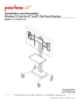
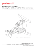
Installation and Assembly:
Wireless Articulating Arm Wall Mount for 42" to 60" Flat Panel
Displays
Model: WL-SA761PU-200
Maximum Load Capacity: 130 lbs (59 kg)
2300 White Oak Circle • Aurora, Il 60502 • (800) 865-2112 • Fax: (800) 359-6500 • www.peerless-av.com
ISSUED: 08-24-12 SHEET #: 180-9036-3 10-31-12
Note: Read entire instruction sheet before you start installation and assembly.
WARNING
• Do not begin to install your Peerless product until you have read and understood the instructions and warnings
contained in this Installation Sheet. If you have any questions regarding any of the instructions or warnings, for US
customers please call Peerless customer care at 1-800-865-2112, for all international customers, please contact
your local distributor.
• This product should only be installed by someone of good mechanical aptitude, has experience with basic building
construction, and fully understands these instructions.
• Make sure that the supporting surface will safely support the combined load of the equipment and all attached
hardware and components.
• Never exceed the Maximum Load Capacity. See page one.
• If mounting to wood wall studs, make sure that mounting screws are anchored into the center of the studs. Use of
an "edge to edge" stud finder is highly recommended.
• Always use an assistant or mechanical lifting equipment to safely lift and position equipment.
• Tighten screws firmly, but do not overtighten. Overtightening can damage the items, greatly reducing their holding
power.
• This product is intended for indoor use only. Use of this product outdoors could lead to product failure and personal
injury.
• This product was designed to be installed on the following wall construction only;
WALL CONSTRUCTION
HARDWARE REQUIRED
•
•
•
•
•
•
•
Included
Included
Included
Included
Contact Qualified Professional
Contact Qualified Professional
Contact Qualified Professional
Wood Stud
Wood Beam
Solid Concrete
Cinder Block
Metal Stud
Brick
Other or unsure?
Tools Needed for Assembly
•
•
•
•
•
•
stud finder ("edge to edge" stud finder is recommended)
phillips screwdriver
drill
3/16" (5mm) drill bit for wood studs, 3/8" (10mm) drill bit for concrete
level
7/16" open end wrench
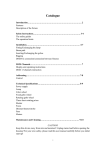
Table of Contents
Parts List.............................................................................................................................................................................3, 4
Wall installation ...................................................................................................................................................................6, 7
Wireless Receiver Assembly and Power Module Assembly Installation............................................................................9-15
Wireless Receiver Assembly and Power Module Assembly Setup ......................................................................................16
Mounting Flat Panel Display .................................................................................................................................................20
Cable Management ..............................................................................................................................................................22
2 of 23
ISSUED: 08-24-12 SHEET #: 180-9036-3 10-31-12
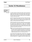
Before you begin, make sure all parts shown are included with your product.
Parts List
A
B
C
D
E
F
G
H
I
J
K
L
M
N
O
P
Q
R
S
T
U
WL-SA761PU-200
Qty. Part #
1 095-P1992
1 095-P1635-2
4 520-1243
4 590-0321
2 520-9262
2 590-1325
16 590-1168
1 560-9716
1 560-9640
2 590-P1326
2 590-P1327
1 560-9646
1 180-1092
1 180-1015
1 590-9468
2 560-9711
8 520-2325
8 530-1021
4 120-1195
4 120-1196
2 590-9469
Description
wall arm assembly
universal adapter bracket
wood screws
concrete anchors
M10 x 15 mm socket head screw
wall plate cover
cable tie .187 x 7.5 lg.
6 mm allen wrench
5 mm allen wrench
rear cable cover
front cable cover
4 mm allen wrench
wireless receiver assembly
power module assembly
cable management sheath
cable tie .04 x 5.75 lg.
decorative screw 1/4-20
lock nut 1/4-20
enclosure mounting bracket, small
enclosure mounting bracket, large
cable tie anchor
A
B
C
F
Parts may appear slightly different than illustrated.
D
E
K
J
G
H
I
L
Q
R
M
N
O
S
T
P
U
3 of 23
ISSUED: 08-24-12 SHEET #: 180-9036-3 10-31-12
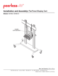
Adapter Bracket Fasteners
M5 x 12mm (4)
(520-1027)
M5 x 25mm (4)
(520-9543)
M4 x 12mm (6)
(504-9013)
M4 x 25mm (4)
(504-1015)
M6 x 12mm (4)
M6 x 20mm (4)
(520-1128)
(520-9402)
M6 x 25mm (4)
(520-1208)
I.D. .22" (4)
(540-1057)
M6 x 30mm (4)
(510-9109)
M8 x 16mm (6)
(520-9257)
M8 x 25mm (4)
(520-1031)
M8 x 40mm (4)
(520-1136)
multi-washer (6)
(580-1036)
I.D. .34" (4)
(540-1059)
Additional Wireless Components
Quick Start Guide
PRO WIRELESS MULTIMEDIA KIT
®
READY
2
Minutes
Model No. HDS200 (-2, -3, -4)
What’s in the Box
1 x Transmitter
1 x Receiver
2 x Stand
1 x Remote Control
1 x IR Flasher
Step 7 While turning on the display device the HD Flow Pro Wireless Multimedia units will be going through the startup process. This process may
take up to two minutes to complete. The Power/Link indicator lights on the Transmitter and the Receiver will be flashing at first. Flashing indicates
that the units are establishing a secure connection. Wait until the connection is successfully established, indicated by the Power/Link indicator
light becoming solid.
1 x IR Extender
1 x Component Adaptor
2 x Power Adapter
1 x Quick Start Guide
1 x Users Manual
Power/Source
Selection Button
Installation and Setup
Tip The IR window
may be easier to
locate with a direct
light shining on
sections of the
front panel of the
component device.
A small flashlight
works well.
Step 1 Connect the Transmitter to the source devices
(Blu-ray™ Disc player, set top box, gaming console, etc.).
Step 2 Connect the provided IR Flasher to the IR-OUT port on the Transmitter.
Find the location of the IR window on your source device and adhere the
IR Flasher eye directly over the IR window on your source device.
NOTE: One IR Flasher eye is to be used for one component device.
Step 8 Select the output that connects the Receiver to the display using
the Power/Source Selection Button or the provided remote control.
The output indicator light will become solid and the HD Flow logo will
appear on the display device.
Step 9 Turn on the desired source device that is connected to
the Transmitter.
Power/Source
Selection Button
Step 10 Select the desired source or device input on the Transmitter
using the Power/Source Selection Button on the remote control.
Step 11 Play the source device content and enjoy up to Full HD 1080p
wireless entertainment experience.
Troubleshooting Tips
Transmitter and/or Receiver Indicator Lights are all Blinking:
• The HD Flow Pro units are establishing a connection. It can take
up to two minutes for the HD Flow Pro units to establish a complete
connection. If after two minutes have passed and the units have not
established a connection, unplug the power cable, wait 30 seconds
and reconnect the power supply to the units.
Tip Repeat Steps
ect
3-11 to connect
ne
more than one
Receiver unitt
(HDS200-2,
HDS200-3,
HDS200-4).
Step 3 Connectt the
th display
di l device
d i (TV,
(TV monitor,
it projector,
j t etc.)
t )
to the Receiver.
Step 4 Install the IR Extender by plugging in the provided IR Extender in to
the IR-IN port on the Receiver and adhering the other end of the IR Extender
to a vertical surface near the output device. Ensure that the IR Extender is in
a line of sight to the remote control that controls your source devices.
NOTE: For Multicast models, receivers two, three and four do not come with an IR Extender. Additional IR Extenders
(HDS-IRE) can be purchased separately; visit peerless-av.com for more information.
Step 5 Power-up the HD Flow Pro Devices.
1. Plug in the power adapter for the Transmitter and the Receiver to nearby
available power outlets.
2. Plug in the power adapter end to the Transmitter and then to the Receiver.
3. The units will automatically turn-on. The average power-on/sync time
is approximately two minutes.
Transmitter or Receiver Power Indicator Light is OFF:
• Check and verify the power supply connection.
Transmitter Input Indicator Light Blinks:
• Make sure that your source device is turned ON and the cable
is properly connected.
• Verify that the Transmitter is set to the appropriate input port.
• Check the resolution from your source device. This may need to
be changed to a resolution supported by the HD Flow Pro Wireless
Multimedia Kit. Reference the Resolution Chart in the HD Flow Pro
Manual for compatibility. Reference your source devices’ manual
for instruction on changing the output resolution.
Receiver Power Indicator Light Blinks:
• Verify that the HD Flow Pro Transmitter and Receiver are within
the recommended range of 131 feet. Physical obstructions such as
walls, floors and ceilings between the Transmitter and Receiver may
decrease the strength of the connection signal and reduce the overall
transmission range.
Step 6 Turn on your display device (TV, monitor, projector, etc.).
•
Check the media source resolution. The display device must be able
to support the resolution of the media source that is being streamed.
Utilizing the INFO button will allow you to see the resolution data that
the display device supports. If the display device supports the highest
resolution of 720p but the source device is outputting 1080p content,
the content needs to be down-scaled to the maximum resolution of the
display device, in this case 720p.
Receiver Output Indicator Light Blinks:
• Make sure that your display device, source device and the HD Flow Pro units
are all turned ON and the Receiver is properly connected to the output device.
Verify that the Receiver is set to the appropriate output port.
Check the resolution setting of your source device. This may need to be
changed to a resolution supported by the HD Flow Pro unit. Reference
the Resolution Chart in the HD Flow Pro Manual for compatibility.
Reference your source devices’ manual for instruction on changing
the output resolution.
•
•
If the above troubleshooting tips do not resolve the issues for a unicast setup,
please reference the Factory Reset Section of the HD Flow Pro Manual. For a
multicast system configuration, please contact Peerless-AV Customer Care at
800-856-2112 for further instruction.
If a connection has been established and the HD Flow logo can be seen
on the display device, but content is not playing:
• Make sure that the input/output cables are properly connected.
• Verify that the Transmitter is set to the appropriate input port.
© 2012 Peerless Industries, Inc. Peerless-AV™ is a trademark of Peerless Industries, Inc. All rights reserved.
HD Flow™ is a trademark of I Do It, LTD. Other parties’ marks are the property of their respective owners. hdflow.com
wireless transmitter (1) vga to rca adapter (1)
(180-1202)
(180-1006)
plastic stand (1)
(180-1205)
remote (1)
(180-1207)
Warning Do not place the HD Flow
Pro units near other devices that
emit excessive amounts of heat.
Increased temperatures may
cause the HD Flow Pro Transmitter
or Receiver unit to malfunction
or stop working.
Quick Start Guide for HD Flow Pro Wireless Multimedia Kit - LIT-0906
install guide (1)
(LIT-0905)
User Manual and Installation Guide
Pro Wireless Multimedia Kit
Models:
HDS200
HDS200-2
HDS200-3
HDS200-4
®
R E ADY
ISSUED: 06-12-12 SHEET #: 180-9023-1
3v battery (1)
(180-0008)
12v power adapter (1)
(180-1004)
ir flasher (1)
(180-1009)
4 of 23
hdmi cable (2)
(600-0234)
instruction sheet (1)
(180-9023)
ISSUED: 08-24-12 SHEET #: 180-9036-3 10-31-12
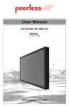
Optional Horizontal Adjustment of Wall Arm on Wall Plate
1
NOTE: If mounting wall arm (A) to wood stud walls, slots on wall plate must align to wood studs.
Determine desired location of display center detailed in step 2.
Measure the distance from the center of wall arm (A) to desired display center. Loosen four 1/4-20 x 17mm screws
using 5mm allen wrench (I). Slide wall arm assembly 4-1/2" to the left or right as shown in figure 1.1. NOTE: Align
bevels (dots) of slide plate with bevels (dots) of wall plate rails as shown in detail 1 then retighten 1/4-20 x 17mm
screws.
Do not adjust arm while display is attached.
Skip to page 6 for Wood Stud Installation.
Skip to page 7 for Concrete and Cinder Block Installation.
1/4-20 X 17MM SCREWS
WALL PLATE
WALL ARM
WALL PLATE RAIL
SLIDE PLATE
DETAIL 1
fig. 1.1
5 of 23
ISSUED: 08-24-12 SHEET #: 180-9036-3 10-31-12
Installation to Double-Stud Wall
WARNING
• Installer must verify that the supporting surface will safely support the combined load of the equipment and all
attached hardware and components.
• Tighten wood screws so that wall plate is firmly attached, but do not overtighten. Overtightening can damage the
screws, greatly reducing their holding power.
• Never tighten in excess of 80 in. • lb. (9 N.M.).
• Make sure that mounting screws are anchored into the center of the stud. The use of an "edge to edge" stud finder
is highly recommended.
• Hardware provided is for attachment of mount through standard thickness drywall or plaster into wood studs.
Installers are responsible to provide hardware for other types of mounting situations.
2
Use a stud finder to locate the edges of the studs and draw a vertical line down the center of each stud. Determine
and mark the desired display center on the wall. Place wall plate template (wall arm) on wall with top mounting slots
9" (229mm) above desired display center as shown in figure 2.1. Level wall plate template (wall arm) on wall and
mark center of four mounting holes making sure that the mounting holes are on the stud centerlines. Drill four 3/16"
(5mm) dia. pilot holes to a depth of 3" (76mm). Attach wall arm (A) to wall using four wood screws (C) as shown in
fig. 2.2.
Level wall plate then tighten all fasteners.
WOOD STUD
WOOD STUD
9"
(229 mm)
A
CS
C
CS = CENTER OF DISPLAY
fig. 2.1
fig. 2.2
6 of 23
ISSUED: 08-24-12 SHEET #: 180-9036-3 10-31-12
Installation to Solid Concrete or Cinder Block
WARNING
• When installing Peerless wall mounts on cinder block, verify that you have a minimum of 1-3/8" (35mm) of actual
concrete thickness in the hole to be used for the concrete anchors. Do not drill into mortar joints! Be sure to mount
in a solid part of the block, generally 1" (25mm) minimum from the side of the block. Cinder block must meet ASTM
C-90 specifications. It is suggested that a standard electric drill on slow setting is used to drill the hole instead of a
hammer drill to avoid breaking out the back of the hole when entering a void or cavity.
• Concrete must be 2000 psi density minimum. Lighter density concrete may not hold concrete anchor.
• Make sure that the supporting surface will safely support the combined load of the equipment and all attached hardware and components.
2
Determine and mark the desired display center on the
wall. Place wall plate template (wall arm) on wall with
top mounting slots 9" (229mm) above desired display
center as shown in figure 2.1. Level wall plate template
(wall arm) on wall and mark center of four mounting
holes making sure that the mounting holes. Drill four
3/8" (10mm) dia. pilot holes to a depth of 3" (76mm).
Insert anchors (D) into holes flush with wall as shown
(right). Place wall arm over anchors and secure with
5/16 x 3" screws (C). Level, then tighten all fasteners.
concrete
surface
1
D
Drill holes and insert anchors (D).
A
2
C
WARNING
D
Place plate (A) over anchors (D) and secure with screws (C).
• Tighten screws so that wall plate is firmly attached,
but do not overtighten. Overtightening can damage
screws, greatly reducing their holding power.
3
• Never tighten in excess of 80 in. • lb.. (9 N.M.).
• Always attach concrete expansion anchors directly
to load-bearing concrete.
Tighten all fasteners.
• Never attach concrete expansion anchors to
concrete covered with plaster, drywall, or other
finishing material. If mounting to concrete surfaces
covered with a finishing surface is unavoidable,
the finishing surface must be counterbored as
shown below. Be sure concrete anchors do not
pull away from concrete when tightening screws. If
plaster/drywall is thicker than 5/8" (16mm), custom
fasteners must be supplied by installer.
CUTAWAY VIEW
INCORRECT
concrete
wall
plate
plaster/
dry wall
SOLID CONCRETE
A
CORRECT
concrete
wall
plate
D
CINDER BLOCK
C
plaster/
dry wall
7 of 23
ISSUED: 08-24-12 SHEET #: 180-9036-3 10-31-12
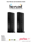
Adapter Bracket Adjustment
NOTE: If display has a VESA 400 horizontal
mounting pattern, skip to step 4 on page 9.
NOTE: For VESA 200x200 or VESA 200x100
mount hole patterns, skip to step 5 on page 12.
3
1/4-20 x 1.25" SCREWS
Remove four 1/4-20 x .6" screws using 5mm allen
wrench (I) and loosen two 1/4-20 x 1.25" screws
1/2 turn to allow for display bracket adjustment.
1/4-20 x .6" SCREWS
3-1
To prevent scratching the display, set a cloth on a flat, level surface that will support the weight of the display.
Place display face side down and refer to display manufacturers instructions for removing obstructions from the
back of the display. Adjust display brackets to align with display mounting holes.
Measure horizontal mounting hole pattern and choose fixed stop-position from chart below.
horizontal mounting hole pattern
10-3/4" - 16-1/16" (273 - 408 mm)
15-1/16" - 21-9/16" (383 - 548 mm)
20-7/16" - 27-9/16" (519 - 700 mm)
fixed stop-position
#1
#2
#3
FIXED STOP-POSTION #3
FIXED STOP-POSTION #2
FIXED STOP-POSTION #1
8 of 23
ISSUED: 08-24-12 SHEET #: 180-9036-3 10-31-12
Wireless Receiver Assembly and Power Module Assembly Installation
4
NOTE: The Wireless Receiver Assembly and Power Module Assembly position can be interchanged based on the
display's connector panel location. Install Wireless Receiver Assembly on the side closest to the connector panel.
Loosely attach the small enclosure mounting brackets (S) on the wireless receiver assembly (M) with two 1/4-20
decorative screws (Q) and two 1/4-20 nuts (R) as shown in fig. 4.1. NOTE: The enclosure mounting bracket can
be installed with the inside notch facing downward if additional side to side adjustment is needed. Attach the
mounting brackets (S), open end of notch facing downward, to the left display bracket with two 1/4-20 decorative
screws (Q) and two 1/4-20 nuts (R) as shown in fig. 4.2.
Position the wireless receiver assembly approximately 1/4" from the universal adapter as shown in detail 2. Once
in position, tighten the four 1/4-20 decorative screws (Q) using 4mm allen wrench (L).
Q
M
1/4"
DETAIL 2
DISPLAY BRACKET
R
M
S
Q
INSIDE NOTCH
R
fig. 4.1
5
fig. 4.2
Loosely attach the enclosure mounting brackets (S) on the power module assembly (N) with two 1/4-20
decorative screws (Q) and two 1/4-20 nuts (R) as shown in fig. 5.1. NOTE: The enclosure mounting bracket can
be installed with the inside notch facing downward if additional side-to-side adjustment is needed. Attach the
mounting brackets (S), open end of notch facing downward, to the right display bracket with two 1/4-20 decorative
screws (Q) and two 1/4-20 nuts (R) as shown in fig. 5.2.
Position the power module assembly approximately 1/4" from the universal adapter as shown in detail 2. Once in
position, tighten the four 1/4-20 decorative screws (Q) using 4mm allen wrench (L).
R
DISPLAY
BRACKET
N
S
Q
fig. 5.2
INSIDE NOTCH
fig. 5.1
9 of 23
ISSUED: 08-24-12 SHEET #: 180-9036-3 10-31-12
Installing Adapter Brackets to Display
WARNING
• Tighten screws so display brackets are firmly attached to display. Do not tighten with excessive force.
Overtightening can cause stress damage to screws, greatly reducing their holding power and possibly causing
screw heads to become detached. Tighten to 40 in. • lb. (4.5 N.M.) maximum torque.
• If screws don't get three complete turns in the display inserts or if screws bottom out and bracket is still not tightly
secured, damage may occur to display or product may fail.
6
Select the screws from the baffled fastener pack that best fit your display and secure to display following step 6-3
or 6-4 on page 11.
NOTE: Top and bottom mounting holes must be used for attaching display brackets. Middle holes should also be
used where the fasteners and displays allow.
Verify that all holes are properly aligned, then tighten screws using a phillips screwdriver.
CENTER DISPLAY BRACKETS VERTICALLY AND
HORIZONTALLY ON BACK OF DISPLAY
X
DISPLAY
X
DISPLAY BRACKETS
Y
Y
NOTE: "X" dimensions should be equal.
"Y" dimensions should be equal.
10 of 23
ISSUED: 08-24-12 SHEET #: 180-9036-3 10-31-12
6-1
NOTE: Wireless Receiver and Power Box
removed for clarity.
DISPLAY
Begin with the longest length screw, hand thread
screw through multi-washer, display brackets (B)
and spacer in that order into display as shown
below. Screw must make at least three full turns
into the mounting hole and fit snug into place.
Do not over tighten. If screw cannot make three
full turns into the display, select a shorter length
screw from the baffled fastener pack. Repeat for
remaining mounting holes, level display brackets
and tighten screws.
SPACER
MULTI-WASHER
SCREW
B
1/4-20 x 1.25" SCREWS
6-2
Center display brackets horizontally and
vertically on back of display. Tighten two 1/4-20
x 1.25" screws. Reinstall four 1/4-20 x .6" screws
using 5mm allen wrench (I) into appropriate
fixed-stop position from chart on page 8.
1/4-20 x .6" SCREWS
11 of 23
ISSUED: 08-24-12 SHEET #: 180-9036-3 10-31-12
Wireless Receiver and Power Module Installation VESA
200 x 200 or VESA 200 x 100 Mounting Pattern
Remove four 1/4-20 x .6" screws using 5mm allen wrench
(I) and loosen two 1/4-20 x 1.25" screws 1/2 turn to allow for
display bracket adjustment.
7
1/4-20 x 1.25" SCREWS
1/4-20 x .6" SCREWS
7-1
Remove four 1/4-20 self tapping screws to detach display brackets from outer mount holes of universal adapter
bracket (B) using 5mm allen wrench (I) as shown in figure 7.1. Reinstall four 1/4-20 self tapping screws to secure
display brackets to inner set of mounting holes on universal adapter bracket (B) as shown in figure 7.2.
OUTER
MOUNTING
HOLES
INNER
MOUNTING
HOLES
DISPLAY
BRACKETS
DISPLAY
BRACKETS
B
B
1/4-20 SELF
TAPPING SCREWS
1/4-20 SELF
TAPPING SCREWS
fig. 7.1
fig. 7.2
To prevent scratching the display, set a cloth on a
flat, level surface that will support the weight of the
display. Place display face side down and place
universal adapter bracket (B) onto display.
B
12 of 23
ISSUED: 08-24-12 SHEET #: 180-9036-3 10-31-12
7-2
Loosely attach the large enclosure mounting bracket
(T) on the power module assembly (N) with two 1/420 decorative screws (Q) and two 1/4-20 nuts (R) as
shown. NOTE: The enclosure mounting bracket can
be installed with the inside notch facing downward if
additional side to side adjustment is needed.
7-3
Loosely attach the large enclosure mounting
bracket (T) on the wireless receiver assembly (M)
with two 1/4-20 decorative screws (Q) and two
1/4-20 nuts (R) as shown. NOTE: The enclosure
mounting bracket can be installed with the inside
notch facing downward if additional side to side
adjustment is needed.
R
R
Q
T
T
N
7-4
Q
M
Align one display bracket with one set of display mounting holes. Place spacers between display bracket and
display. Place the enclosure mounting brackets (T), open end of notch facing downward, between the display
bracket and spacers.
Begin with the longest length screw, hand thread screw through the multi-washer, display brackets, enclosure
mounting brackets (T) and spacer into display as shown. Screw must make at least three full turns into the
mounting hole and fit snug into place. Do not over tighten. If screw cannot make three full turns into the display,
select a shorter length screw from the baffled fastener pack.
Center display brackets vertically. Position the enclosure mounting brackets (T) horizontally making sure that the
notch in the brackets are seated on the screws. Tighten screws.
SCREW
MULTIWASHER
SPACER
DISPLAY
BRACKET
T
13 of 23
ISSUED: 08-24-12 SHEET #: 180-9036-3 10-31-12
7-5
Slide universal adapter bracket (B) to the opposite side and align second display bracket with second set of
display mounting holes.
Hand thread screws through the multi-washer, display brackets, enclosure mounting brackets (T) and spacer into
display as shown. Tighten all screws.
MULTISCREW
WASHER
SPACER
B
DISPLAY
BRACKET
T
7-6
Center universal adapter bracket (B) horizontally on back of display as shown in figure 7.3.
Tighten two 1/4-20 x 1.25" screws. Reinstall four 1/4-20 x .6" screws using 5mm allen wrench (I) into fixed-stop
position 1 as shown in figure 7.4.
B
1/4-20 x 1.25" SCREWS
FIXED STOP POSITION #1 WITH
1/4-20 x .6" SCREWS
fig. 7.3
fig. 7.4
14 of 23
ISSUED: 08-24-12 SHEET #: 180-9036-3 10-31-12
7-7
Position the wireless receiver assembly (M) and power module assembly (N) approximately 1/4" from the
universal adapter (B) as shown. Once in position, tighten the four 1/4-20 decorative screws (Q) using using 4mm
allen wrench (L) and a 7/16" open end wrench.
Skip to step 8.
DISPLAY
B
1/4"
1/4"
M
N
Q
Q
Wireless Receiver Assembly and Power Module Assembly Setup
8
Remove the two #8 screws securing the cover of the wireless receiver assembly as shown in detail 3. Open the
enclosure to expose the wireless receiver and IR unit. Remove the two M5 x 10mm phillips screws and open the
power enclosure as shown in detail 4.
M5 x 10mm SCREWS
DETAIL 3
#8 SCREW
DETAIL 4
15 of 23
ISSUED: 08-24-12 SHEET #: 180-9036-3 10-31-12
9
Untie the wireless receiver power adapter cord and route as shown below. Plug the end of the power adapter into
the outlet marked DC on the wireless receiver as shown in detail 5. Coil up the excess cord and secure with a
cable tie (P). Store the coiled cord between the power adapter and the power module wall as shown.
WIRELESS RECEIVER POWER
ADAPTER
DISPLAY NOT
SHOWN FOR
CLARITY
US
B
LA
N
DC
10
DETAIL 5
Locate the IR receiver inside of the wireless receiver enclosure shown in figure 10.1. Remove the tie from the cable
and position the receiver on the display within line of sight of your remote as shown in figure 10.2. Remove the
adhesive backing from the IR receiver eye and attach to the display. Coil up the excess cord near the wireless
receiver enclosure and secure with a cable tie (P). Store the coiled cord back inside of the enclosure.
fig. 10.2
IR RECIEVER
IR RECIEVER
fig. 10.1
16 of 23
ISSUED: 08-24-12 SHEET #: 180-9036-3 10-31-12
11
Close the top cover of the wireless receiver enclosure, making sure that the IR receiver cord runs underneath the
cable opening as shown in figure 11.1. Re-install the two #8 screws.
#8 SCREWS
CABLE OPENING
fig. 11.1
12
Install the cable tie anchor (U) onto the inside back
wall of the power module assembly (N). Remove the
adhesive backing from the anchor and press into
place in the area shown.
13
U
DISPLAY POWER
CORD
N
14
Plug the power cord from your display into the triple
tap grounded outlet as shown. Coil up the excess
cord and secure with a cable tie (G), inserting it
through the cable tie anchor (U) and around the
coiled cord.
TRIPLE TAP
GROUNDED OUTLET
G
Close the top cover of the power module assembly
(N), making sure that the power adapter cords run
underneath the cable opening as shown below.
Re-install the M5 x 10mm phillips screws.
15
Place the cords inside the cable management sheath
(O) by pushing the cables through the slit in the
sheath. NOTE: The sheat may need to be trimmed
to length before installing cords.
O
M5 x 10mm SCREWS
CABLE
OPENING
17 of 23
ISSUED: 08-24-12 SHEET #: 180-9036-3 10-31-12
16
Position the cable management sheath and secure with two cable ties in the approximate locations shown below
and detail 7. Do not overtighten cable ties.
O
G
DETAIL 6
18 of 23
ISSUED: 08-24-12 SHEET #: 180-9036-3 10-31-12
WARNING
• Do not lift more weight than you can handle. Use additional man power or mechanical lifting equipment to safely
handle placement of the display.
• Do not tighten screws with excessive force. Overtightening can cause damage to mount. Tighten M10 x 15mm
screws (E) to 40 in. • lb. (4.52 N.M.) maximum torque.
Mounting Flat Panel Display
17
Hook M10 x 15mm screws into keyslots of wall arm adapter plate (A) as shown figure 17.1.
DISPLAY NOT
SHOWN FOR
CLARITY
1/4"
M10 X 15MM SCREW
B
A
fig. 17.1
17-1 fasteners with 6mm allen wrench (H).
Insert two M10 x 15mm screws (E) into bottom holes of adapter plate as shown in figure 17.2. Tighten all
DISPLAY NOT
SHOWN FOR
CLARITY
B
E
ADAPTER
PLATE
fig. 17.2
19 of 23
ISSUED: 08-24-12 SHEET #: 180-9036-3 10-31-12
Adjustment of Flat Panel Display
WARNING
• M10 x 15mm screws (E) must be securly tightened before changing orientation of wall arm assembly (A). Failure to
lock adapter bracket can cause display to come off of mount.
18
FOR PORTRAIT OR LANDSCAPE DISPLAY ORIENTATION: Remove two M5 x 12mm screws, one M5 x 6mm
screw and rotation block from top of tilt head as shown in top view and rear view. Gently grasp sides of display and
rotate display into portrait or landscape position as shown in figure 18.1 and reinstall rotation block with two
M5 x 12mm screws and one M5 x 6mm screw. NOTE: M5 x 6mm screw required in landscape orientation only.
ROTATION BLOCK
M5 X 6MM SCREWS
M5 X 12MM SCREWS
TOP VIEW
M5 X 6MM
SCREWS
M5 X 12MM
SCREWS
ROTATION BLOCK
fig. 18.1
REAR VIEW
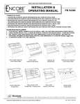
19
TILT Adjustment: Adjust tension knob on side of
mount to desired tension to enable tilt adjustment
and balance your display size and weight. Push
or pull from top or bottom of display to adjust tilt
as shown. The tilt can be adjusted to a maximum
of 10° forward or 5° backward. Retighten tension
knob. NOTE: For larger displays, tension screw on
opposite side of mount may need to be tightened
using 5/32" allen wrench (L).
ROLL Adjustment: Rotate display 5° clockwise or
counter-clockwise, level display then tighten
M5 x 10mm screws as shown in detail 8.
FOR VERTICAL HEIGHT ADJUSTMENT: Tighten
or loosen M8 x 40mm screws to achieve ± 1" of
vertical height adjustment as shown in detail 7.
NOTE: M8 x 40mm screws must be turned an equal
number of times.
TENSION
KNOB
M5 X 10MM SCREWS
CAUTION
• Do not tighten screws with excessive force.
• Be careful not to pinch fingers when opening and
closing mount from the wall.
M8 X 40MM
SCREWS
20 of 23
DETAIL 7
ISSUED: 08-24-12 SHEET #: 180-9036-3 10-31-12
20
Plug the component cable(s) from your display
(HDMI shown) into the wireless receiver.
COMPONENT
CABLE
HD
21
Plug extension cord (not included) into the tripe tap
grounded outlet.
M
I-O
UT
EXTENSION CORD
Cable Management
22
NOTE: Make sure extension cord (not included) has
enough slack to allow full movement of the arm.
23
Run extension cord (not included) through top
or bottom of arm (A). Lock cables into place by
snapping cable covers (J & K) onto mount as
shown. Display may have to be moved for easy
access.
Snap wall plate covers (F) to top and bottom of
wall plate rails as shown.
WALL PLATE RAIL
F
Optional: If additional cable management is
required route cable ties (G) through slots of arm (A)
as shown in detail 8.
J
K
A
SLOT
CABLE
G
DETAIL 8
21 of 23
ISSUED: 08-24-12 SHEET #: 180-9036-3 10-31-12
Arm Tension Adjustment
WARNING
• Do not remove screw or loosen screw until it is no longer engaged with the mount. Doing so may cause the display
to fall.
• If screws become loose over time, tighten screws as necessary. Tighten screws to 50 in • lbs (5.6 N.m.) maximum
torque.
24
If more or less tension is desired in the arm pivot points, do the following:
• To increase tension, turn socket screw clockwise with 5mm allen wrench (I). NOTE: Tighten screws to
50 in • lbs (5.6 N.m.) maximum torque.
• To reduce tension, turn socket screw counter-clockwise with 5mm allen wrench (I). NOTE: Do not turn more
than half a turn.
TENSION SCREW
TENSION SCREWS
25
Plug extension cord into power source.
To complete the installation of your wireless mount, please refer to the HD Flow™ User's Manual and the HD
Flow™ Install Guide included.
22 of 23
ISSUED: 08-24-12 SHEET #: 180-9036-3 10-31-12
© 2012 Peerless Industries, Inc.
Peerless-AV® is a registered trademark of Peerless Industries, Inc. All rights reserved.
All other brand and product names are trademarks or registered trademarks of their respective owners.
LIMITED WARRANTY
Peerless Industries, Inc. (“Peerless-AV®”) warrants to original end-users of Peerless-AV® products that Peerless-AV® products will be free from defects in material
and workmanship, under normal use, for the periods listed below, from the date of purchase by the original end-user. At its option, Peerless-AV® will repair or
replace with new or refurbished products or parts, or refund the purchase price of any Peerless-AV® product which fails to conform with this warranty.
In no event shall the duration of any implied warranty of merchantability or fitness for a particular purpose be longer than the period of the applicable
express warranty set forth above. Some states do not allow limitations on how long an implied warranty lasts, so the above limitation may not apply to you.
This warranty does not cover damage caused by (a) service or repairs by the customer or a person who is not authorized for such service or repairs by PeerlessAV®, (b) the failure to utilize proper packing when returning the product, (c) incorrect installation or the failure to follow Peerless-AV®’s instructions or warnings
when installing, using or storing the product, or (d) misuse or accident, in transit or otherwise, including in cases of third-party actions and force majeure. This
warranty also does not cover corrosion or rust resulting from damaged, scratched or chipped paint or other surfaces.
In no event shall Peerless-AV® be liable for incidental or consequential damages or damages arising from the theft of any product, whether or not
secured by a security device which may be included with the Peerless-AV® product. Some states do not allow the exclusion or limitation of incidental or
consequential damages, so the above limitation or exclusion may not apply to you.
This warranty is in lieu of all other warranties, express or implied, and is the sole remedy with respect to product defects. No dealer, distributor, installer or other
person is authorized to modify or extend this Limited Warranty or impose any obligation on Peerless-AV® in connection with the sale of any Peerless-AV® product.
This warranty gives specific legal rights, and you may also have other rights which vary from state to state.
Product
Warranty Period
Mounts
Furniture
Cables
Cleaning Products
Electronic Products and components
5 years
1 year
25 years
1 year
1 year
www.peerless-av.com
23 of 23
© 2012 Peerless Industries, Inc.
ISSUED: 08-24-12 SHEET #: 180-9036-3 10-31-12