1
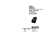
Dear Valued Customer,
Thank you for purchasing Patton Electronics products! We do
appreciate your business. I trust that you find this user manual helpful.
USER
MANUAL
We manufacture one of the widest selections of data
communications products in the world including CSU/DSU's, network
termination units, powered and self-powered short range modems, fiber optic
modems, interface converters, baluns, electronic data switches, data-line surge
protectors, multiplexers, transceivers, hubs, print servers and much more. We
produce these products at our Gaithersburg, MD, USA, facility, and can
custom manufacture products for your unique needs.
MODEL 3054, 3056, 3058
We would like to hear from you. Please contact us in any of the
following ways to tell us how you like this product and how we can meet your
product needs today and in the future.
Web:
Sales E-mail:
Support E-mail:
Phone - Sales
Phone - Support
Fax:
Mail:
RS-232 and RS-422 Limited
Distance Multiplexers
http://www.patton.com
[email protected]
[email protected]
(301) 975-1000
(301) 975-1007
(301) 869-9293
Patton Electronics Company
7622 Rickenbacker Drive
Gaithersburg, MD 20879 USA
We are committed to a quality product at a quality price. Patton
Electronics is BABT and ISO 9001 certified. We meet and exceed the highest
standards in the industry (CE, UL, etc.).
It is our business to serve you. If you are not satisfied with any
aspect of this product or the service provided from Patton Electronics or its
distributors, please let us know.
Thank you.
Burton A.Patton
Vice President
P.S. Please tell us where you purchased this product.
_________________________________________________________
_________________________________________________________
_________________________________________________________
_________________________________________________________
_________________________________________________________
_________________________________________________________
_________________________________________________________
Part# 07M305X-B
Doc# 043011UB
Revised 6/18/98
CERTIFIED
An ISO-9001
Certified Company
SALES OFFICE
(301) 975-1000
TECHNICAL SUPPORT
(301) 975-1007
http://www.patton.com
1.0 WARRANTY INFORMATION
1.3 SERVICE
Patton Electronics warrants all Model 305X Series components to
be free from defects, and will—at our option—repair or replace the
product should it fail within one year from the first date of shipment.
This warranty is limited to defects in workmanship or materials, and
does not cover customer damage, abuse, or unauthorized modification.
If this product fails or does not perform as warranted, your sole
recourse shall be repair or replacement as described above. Under no
condition shall Patton Electronics be liable for any damages incurred
by the use of this product. These damages include, but are not limited
to, the following: lost profits, lost savings, and incidental or
consequential damages arising from the use of or inability to use this
product. Patton Electronics specifically disclaims all other warranties,
expressed or implied, and the installation or use of this product shall be
deemed an acceptance of these terms by the user.
All warranty and non-warranty repairs must be returned freight
prepaid and insured to Patton Electronics. All returns must have a
Return Materials Authorization number on the outside of the shipping
container. This number may be obtained from Patton Electronics
Technical Support: (301) 975-1007; http://www.patton.com; or,
[email protected].
NOTE: Packages received without an RMA number will not be
accepted.
Patton Electronics' Technical Support is also available to answer
any questions that might arise concerning the installation or use of your
Patton Model 305X Series product. Technical Support hours: 8AM to
5PM EST, Monday through Friday.
1.1 RADIO AND TV INTERFERENCE
The Model 305X Series generate and use radio frequency energy,
and if not installed and used properly—that is, in strict accordance with
the manufacturer's instructions—may cause interference to radio and
television reception. The Model 305X Series has been tested and
found to comply with the limits for a Class A computing device in
accordance with the specifications in Subpart J of Part 15 of FCC rules,
which are designed to provide reasonable protection from such
interference in a commercial installation. However, there is no
guarantee that interference will not occur in a particular installation. If
the Model 305X Series does cause interference to radio or television
reception, which can be determined by disconnecting the unit, the user
is encouraged to try to correct the interference by one or more of the
following measures: moving the computing equipment away from the
receiver, re-orienting the receiving antenna and/or plugging the
receiving equipment into a different AC outlet (such that the computing
equipment and receiver are on different branches).
1
2
2.0 GENERAL INFORMATION
Thank you for your purchase of this Patton Electronics product.
This product has been thoroughly inspected and tested and is
warranted for One Year parts and labor. If any questions arise during
installation or use of the unit, contact Patton Electronics Technical
Support at (301) 975-1007.
2.1 FEATURES
• Multiplexes four, six or eight async RS-232 or RS-422 devices onto
two twisted pair, at distances to 6000 ft between muxes
• Operates over 2 dedicated twisted pair wires
• Sub-channels operate full duplex at rates up to 19,200 bps
• Passes through end to end software flow control characters
• Model 3054/AR and 3056/AR allow end-to-end
3.0 CONFIGURATION
Models 3054 and 3056 require no configuration. If you have
Models 3054 or 3056, proceed to Section 4.0 Installation. For most
applications, the Model 3058 also requires no configuration. However,
if you need to connect a Model 3058 to a Patton Model 358 on the
main (multiplexed) channel, you must modify an internal jumper strap
setting to make the two units compatible with each other. This section
shows how to set the jumper strap.
3.1 MODEL 305X/A TO MODEL 358 COMPATIBILITY STRAP
Models 3054/A, 3056/A and 3058/A can be configured to be
backward-compatible with the previous generation 8-channel
multiplexer--Patton Electronics Model 358. To make the 305X
backward-compatible on the main channel, you must remove the Model
358 Compatibility Jumper switch located on the top of the PC board
(see Figure 1, below).
RTS/CTS flow control
• Independent and variable data rates, start/stop bits, and other data
parameters for all sub-channels
• Built-in loopback and line tests allow convenient troubleshooting
• Front Panel LEDs show data activity and test status
Model 358 Compatibility
Jumper
2.2 DESCRIPTION
The Patton Model 305X Series Short Range Multiplexer is two
devices in one: a time division multiplexer and a short range modem.
Operating full duplex over a two dedicated twisted pair wires, the Model
305X Series allows up to four, six, or eight serial RS-232 or RS-422
devices to share two twisted pair to communicate at distances up to
6000 feet.
Each of the Model 305X sub-channels can transmit data
simultaneously at data rates up to 19.2 kbps without the need for user
configuration. Additionally, each sub-channel can operate at a different
rate and with different asynchronous data format (word length,
start/stop bits, etc.)
The Model 305X Series features built-in local and remote
loopback tests that allow easy setup and configuration. Front panel
LEDs show data activity for each port as well as power and test
conditions. The 305X Series allow software flow control by passing
software commands unhindered through the units. In addition, Models
3054AR and 3056AR offer end-to-end RTS/CTS flow control.
3
Figure 1: Model 358 Compatibility Jumper
Figure 2, below, shows the two possible settings of the Model 358
Compatibility jumper. The jumper settings are described in the table
following Figure 2.
Model 358 Compatibility
Normal Mode (default)
Figure 2: Model 358 Compatibility Jumper
Jumper Position
Compatibility Mode
Jumper strap in place
Normal (default setting)
Jumper strap removed
Backwards Compatible with Model 358
4
4.0 INSTALLATION
This section describes how to connect each Model 305X to the RS232 or RS-422 sub-channel devices, to another Model 305X over the
main channel, and to the power supply.
4.1 .2 SUB-CHANNEL CONNECTIONS
The RJ-45 female sub-channel ports on the back of the Model
3054, 3056, and 3058 are labeled 1 - 4 (Model 3054), 1 - 6 (Model
3056) and 1 - 8 (Model 3058). Each sub-channel port designates
single communication path from the local multiplexer to the remote
multiplexer. That is, the serial device connected to port 1 on the local
multiplexer will communicate with the serial device that is connected to
port 1 on the remote multiplexer. Figure 3 shows the port connections
on the rear of the Model 3058.
Sub-Channels
Main Channel
Power Jack
CHANNELS
POWER
8
7
6
5
4
3
2
1
LINE
Figure 3: Model 3058 Port Connections
4.1.1 RS-232 Sub-Channel Connections
The Model 305X Series multiplex and de-multiplex data signals
from four, six, or eight EIA-232 DTE (terminals, PCs) DCE (modems)
devices. Most DTE and DCE devices use a D-Sub 25 or D-Sub 9
connector to transmit and receive data as well as operate flow control.
Since the sub-channel ports on the Model 305X Series are modular RJ45 jacks, you will need an adapter cable to make the proper
connections.. Figure 4, below, shows the pin assignments on the RJ45 sub-channel modular jack.
1 no connection
2 no connection
1
3 no connection
2
3
4 (SG)
4
5
5 (TX Data) from 305X
6
6 (RX Data) to 305X
7
8
7 (RTS) from 305X*
8 (CTS) to 305X*
Every RS-232 serial device connected to a Model 305X Series unit
sub-channel must have a special interface cable. On one end, this
interface cable must have an RJ-45 male plug; on the other end, the
cable must have a connector that adapts to your RS-232 serial device.
The diagrams below show pin connections between the Model 305X
sub-channels and common RS-232 interfaces. You may use these
diagrams to construct your own cables, or you may purchase cables
from Patton Electronics.
RS-232 (PC-XT or other DTE)
DB-25 Pin No.
Model 3054 or 3056
RJ-45 Pin No.
7 (SG)
3 (RCV)
2 (XMT)
4 (RTS)
5 (CTS)
6 (DSR)
8 (DCD)
20 (DTR)
4 (SG)
5 (XMT)
6 (RCV)
8 (CTS)*
7 (RTS)*
RS-232 (Modem or other DCE)
DB-25 Pin No.
7 (SG)
3 (XMT)
2 (RCV)
5 (CTS)
4 (RTS)
6 (DSR)
8 (DCD)
20 (DTR)
Model 3054 or 3056
RJ-45 Pin No.
4 (SG)
5 (XMT)
6 (RCV)
8 (CTS)*
7 (RTS)*
RS-232 (PC-AT or other DTE)
DB-9 Pin No.
Model 3054/3056/3058 (DCE)
RJ-45 Pin No.
5 (SG)
2 (RCV)
3 (XMT)
7 (RTS)
8 (CTS)
1 (DSR)
4 (DCD)
6 (DTR)
4 (SG)
6 (XMT)
5 (RCV)
8 (RTS)*
7 (CTS)*
Figure 4: Model 305X RJ-45 Sub-Channel Pin Numbers
*NOTE: Hardware flow control signals are available only on RS-232
Versions of Models 3054AR and 3056AR (See Section 4.2.4 Flow
Control Requirements).
5
*NOTE: Hardware flow control signals available only on Models
3054/AR and 3056/AR (See Section 4.2.4 Flow Control
Requirements).
6
4.2.2 RS-422 Sub-Channel Connections
4.2.3 Extending RS-232 Sub-Channel Distances
Similar to the Model 305X, the Models 305X-422 Series multiplex
and de-multiplex signals from four or six, or eight EIA-422 devices.
EIA-422 devices may use D-Sub 25, D-Sub-9, RJ-45 or another
connector type to transmit and receive data and operate flow control..
As with the Model 305X, you will need an adapter cable to make the
proper connections. Figure 5, below, shows the pin assignments on the
RJ-45 sub-channel modular jack on the 305X-422 Series.
You can also multiplex signals from sub-channel devices that are
located more than 50 feet away from the Model 305X. Use a Patton
Model 305X-422 with a Patton Model 222N RS-232 to RS-422 converter
(see Appendix C for specific model numbers).
1
2
3
4
5
6
7
8
1 no connection
2 (RCV-) to 305X-422
3 (XMT-) from 305X-422
4 (SG) Signal Ground
5 (XMT+) from 305X-422
6 (RCV+) to 305X-422
7 no connection
8 no connection
As Figure 6 below illustrates, the Model 222N replaces the modular
to D-shell converter at the device end. This set-up allows sub-channel
cable runs up to 1000 feet over two twisted pair wire. Call Patton
Technical Support at for more information about the Model 222N.
Model 222N
Model 222N
1000 ft on UTP
1 Mile on UTP
Figure 5: Model 305X-422 RJ-45 Sub-Channel Pin Numbers
CHANNELS
The diagrams below show the pinning of two RS-422 patch cables:
DB-25 (RS-530) to RJ-45 and DB-9 (RS-449) to RJ-45. Because RS422 is a balanced interface, you should always use twisted pair wire for
RS-422 cable (See Appendix B). Using low capacitance twisted pair
cable between 19 and 24 AWG, you should be able to attain subchannel distances up to 1000 ft. Please be careful to observe the
correct wire pairing as shown below.
RS-530 (422)
DB-25 Pin No.
Model 305X-422
RJ-45 Pin No.
2 (XMT+)
14 (XMT-)
6 (RCV+)
2 (RCV-)
3 (RCV+)
16 (RCV-)
5 (XMT+)
3 (XMT-)
RS-449 (422)
DB-9 Pin No.
Model 305X-422
RJ-45 Pin No.
3 (XMT+)
9 (XMT-)
6 (RCV+)
2 (RCV-)
4 (RCV+)
6 (RCV-)
5 (XMT+)
3 (XMT-)
7
TESTS
CHANNELS
TESTS
Figure 6. RS-232 sub-channel distance extension
4.2.4 Flow Control Requirements
All versions of the 305X Series accomodate flow control. Flow
control is a method whereby devices that process data more slowly (i.e.
printers) can request faster processing devices (i.e. PCs) to temporarily
stop and then restart data transmission. This gives a slower processing
device the ability to clear its receive buffer to accept additonal data. All
versions of Model 305X operate with software flow control. Models
3054AR and 3056AR may also operate with RTS/CTS (hardware) flow
control.
Software Flow Control
The Model 305X Series is transparent to software flow control
method on the sub-channel ports. Both sub-channel devices must be
set to XON/XOFF or ACK/NAK or any other end-to-end software flow
control method. The Model 305X simply passes the software flow
control parameters through from end-to-end without modification.
(continued)
8
5.0 OPERATION
RTS/CTS Flow Control (Models 3054AR and 3056AR Only)
In addition to software flow control capability, Models 3054AR and
3056AR offer end-to-end RTS/CTS flow control capability. When using
RTS/CTS flow control, the RTS and CTS signals are multiplexed into
the composite data stream. The multiplexed RTS/CTS signals are then
demultiplexed and passed to the appropriate sub-channel device at
opposite end.
4.3 MAIN CHANNEL CONNECTIONS
Once the Model 305X Series is properly installed, it should operate
transparently. This section describes the LED status indicators, and the
built-in loopback test modes.
5.1 LED STATUS INDICATORS
The Model 305X Series feature front panel LEDs that monitor
power, the DTE or DCE signals, link status and test modes. Figure 7
(below) shows the front panel location of each LED. Following Figure 7
is a description of each LEDs function.
The main channel port on the back of the Model 305X Series is a
female RJ-45 modular jack. The primary connection between the two
muxes must be dry, unconditioned twisted pair, 19 - 26 AWG (See
Appendix B for optimal cable characteristics). The wiring between the
wall plates must be crossed over, with pairing as shown below:
Model 3058 8-Channel Limited Distance Multiplexer
2
1
3
4
5
6
7
8
TD -
Model 305X Series
RJ-45 Pin No.
Sync./
Link
- Remote Loop
- Normal
- Local Loop
RD -
Model 305X Series
RJ-45 Pin No.
TESTS
Figure 7. Model 3054/56/58 front panel switch and LEDs
Pair 1
{
4 (XMT)
5 (XMT)
4 (XMT)
5 (XMT)
{
6 (RCV)
3 (RCV)
6 (RCV)
3 (RCV)
TD and RD
glow red to indicate idle condition of binary “1”
data on respective channel. Green indicates
binary “0” data.
4.4 AC POWER CONNECTION
RTS
Power is supplied to the Model 305X Series by a 9-12 VAC, 200mA
wall mount transformer. This transformer connects to the Model 305X
Series by means of a cannon jack on the rear panel. The Model 305X
is powered-up as soon as it is plugged into an AC outlet–there is no
power switch.
glows green to indicate that the RS-232 RequestTo-Send signal from the terminal is active (RS-232
Versions: Models 3054AR and 3056AR only)
CTS
glows green to indicate that the RS-232 ClearTo-Send signal from the Model 305X is active
(RS-232 Versions: Models 3054A and 3056AR
only)
Link
glows green to indicate connection to the remote
multiplexer.
Local
Loop
glows green when the local multiplexer enters
the Local Loop test mode
Remote
Loop
glows green when the local multiplexer enters
the Remote Loop test mode
Pair 2
4.4.1 120 VAC Power (US)
The 120 VAC adapter supplied with the standard version of the
Model 305X is a “wall mount” type, and may be plugged into any
approved 115 VAC wall plug.
4.4.2 230 VAC Power (IEC)
The 230 VAC adapter supplied with the “international” version of the
Model 305X is equipped with an IEC-320 shrouded male connector.
This connects with one of several available country-specific power
cords (see the ordering information in Appendix C). You may
purchase these power cords from Patton Electronics, or from a local
vendor of your choice.
9
10
5.2 TEST MODES
5.2.2 DTE Remote Loopback
The Model 305X Series has three test modes: Local Loopback,
Remote Loopback and DTE Remote Loopback. This section tells you
how to use these test modes to isolate cabling or multiplexer problems.
The DTE Remote Loopback test allows you to evaluate the
multiplexers and their connection path by using the local DTE. In order
to fully test both units as well as the twisted pair connection path, you
will need install the enclosed RJ-45 loopback adapter into the specific
remote sub-channel modular jack. Figure 9 shows an example of the
Remote Loopback test with the RJ-45 loopback adapter attached to the
remote multiplexer.
5.2.1 Local Loopback
The Local Loopback test allows you to evaluate the integrity of the
DTE cable and the local Model 305X. Any data sent to the local Model
305X in this test mode will be echoed (returned) back to the user
device. (See Figure 8, below.) For example, characters typed on the
keyboard of a terminal will appear on the terminal screen.
Figure 9 . Line Test
To use this test follow the instructions below:
Figure 8. Local Loopback Test
To use the local loopback test, follow these instructions.
1.
Set the front panel switch of the mux being tested to local
loopback. The corresponding LED should glow.
2.
On a terminal connected to one of the sub-channel ports, key
a character string. You should see those same characters
echoed back on the terminal screen.
3.
If the keyed character string does not echo on the terminal
screen, check all sub-channel connections for continuity and
proper pinning.
1.
Install the RJ-45 loopback adapter into the sub-channel of
the remote multiplexer as shown above in Figure 9. For
instance, if you are testing channel 1, install a loopback
adapter into the sub-channel 1 RJ-45 jack on the remote
multiplexer.
2.
Set the front panel switch of the local multiplexer and the
remote multiplexer to NORMAL.
3.
On a terminal connected to the sub-channel port to be tested,
key a character string. You should see those same characters
echoed back on the terminal screen after they have passed
through the local multiplexer, through the cable and remote
multiplexer, and then back to the through the cable to the
multiplexer and the attached terminal.
4.
If the above test exhibits bit errors or does not work at all,
check all sub-channel and main channel connections for
continuity an proper pinning.
5.2.2 Remote Loopback
The Model 305X offers a second test that evalulates the integrity of
the local and remote multiplexers. With the local multiplexer in
REMOTE LOOPBACK mode and the remote multiplexer set to
NORMAL, the local mux sends a low frequency pulse to the remote
mux over the twisted pair wire. If the two muxes and the twisted pair
cable are functioning properly together, you will see the remote
multiplexers RECEIVE DATA LEDs blinking together. If you have a RJ45 loopback adapter connected to the remote sub-channel ports, the
remote multiplexers TRANSMIT DATA LEDs and the local multiplexers
RECEIVE DATA LEDs will also blink.
11
12
APPENDIX A
APPENDIX B
PATTON MODEL 305X SERIES SPECIFICATIONS
MODEL 305X SERIES CABLE RECOMMENDATIONS
Transmission Lines:
Range:
Interfaces:
Data Rates:
Indicators:
Test Modes:
Connectors:
Power Supply:
Temperature
Range:
Altitude:
Humidity:
Dimensions:
Weight:
Certifications:
Main channel and RS-422 sub-channels,19
to 26 AWG twisted pair; RS-232 subchannels, flat silver cable
6000 feet (1800m) over twisted pair 24 AWG
between multiplexers; 1000 feet (304m) on
RS-422 sub-channels; 50 feet (15m) on
RS-232 sub-channels
Asynchronous RS-232, ITU/CCITT
0 - 19.2 kbps on sub-channels
Transmit Data, Receive Data, Link, Local
Loopback, Line Test
Local loopback, Line Test
RJ-45 female on main and sub-channels
9-12 Volts AC
0-600C (32-1400F)
0-15,000 feet (0-4572 m)
5 to 95% non-condensing
8.5" W x 3.5”L x 1.5”H (21.0 x 8.9. x 3.8 cm)
Multiplexer, 0.65 lbs; Power supply, 0.5 lbs
Emissions: FCC part 15 Class A,
13
The Patton Model Series operates at frequencies of 160 kHz or less
and has been performance tested by Patton technicians using twistedpair cable with the following characteristics:
Wire Gauge
Capacitance
Resistance
19 AWG(.9mm)
22 AWG(.6m)
24 AWG(.5mm)
26 AWG(.4mm)
83nF/mi or 15.72 pF/ft.
83nF/mi or 15.72 pF/ft.
83nF/mi or 15.72 pF/ft.
83nF/mi or 15.72 pF/ft.
.0163 Ohms/ft.
.0326 Ohms/ft.
.05165 Ohms/ft.
.08347 Ohms/ft.
To gain optimum performance from the Model 305X Series, please
keep the following guidelines in mind:
•
Always use twisted pair wire—this is not an option.
•
Use twisted pair wire with a capacitance of 20pF/ft or less.
•
Avoid twisted pair wire thinner than 26 AWG (i.e. avoid higher
AWG numbers than 26).
•
Use of twisted pair with a resistance greater than the above
specifications may cause a reduction in maximum distance
obtainable. Functionality should not be affected.
14
APPENDIX C
PATTON MODEL 305X SERIES FACTORY REPLACEMENT PARTS
APPENDIX D
PATTON MODEL 305X LOOPBACK ADAPTER PIN ASSIGNMENTS
RS-232 LOOPBACK ADAPTER PLUG
Patton Part # Description
Model 305X - LB
RJ-45 Pin No.
222NM-RJ45....................RS-232 (male) to RS-422 Converter
222NF-RJ45 ....................RS-232 (female) to RS-422 Converter
222N9M-RJ45..................RS-232 (DB-9 male) to RS-422 Converter
222N9F-RJ45 ...........RS-232 (DB-9 female) to RS-422 Converter
080510ACB .............. ......Power Supply, 120V, 10VAC
080512ACI................ ......Power Supply, 230V, 12VAC
4 (SG)
5 (XMT)
6 (RCV)
RS-422 LOOPBACK ADAPTER PLUG
Model 305X-422-LB
RJ-45 Pin No.
6 (RCV+)
2 (RCV-)
5 (XMT+)
3 (XMT-)
15
16