1
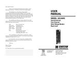
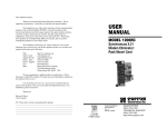
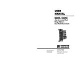
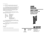
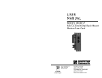
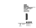
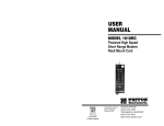
Dear Valued Customer,
Thank you for purchasing Patton Electronics products! We do
appreciate your business. I trust that you find this user manual helpful.
USER
MANUAL
We manufacture one of the widest selections of data
communications products in the world including CSU/DSU's, network
termination units, powered and self-powered short range modems, fiber optic
modems, interface converters, baluns, electronic data switches, data-line surge
protectors, multiplexers, transceivers, hubs, print servers and much more. We
produce these products at our Gaithersburg, MD, USA, facility, and can
custom manufacture products for your unique needs.
MODEL 1110ARC
We would like to hear from you. Please contact us in any of the
following ways to tell us how you like this product and how we can meet your
product needs today and in the future.
Web:
Sales E-mail:
Support E-mail:
Phone - Sales
Phone - Support
Fax:
Mail:
Asynchronous, RS-232
Fiber Optic
Rack Card Modem
http://www.patton.com
[email protected]
[email protected]
(301) 975-1000
(301) 975-1007
(301) 869-9293
Patton Electronics Company
7622 Rickenbacker Drive
Gaithersburg, MD 20879 USA
We are committed to a quality product at a quality price. Patton
Electronics is BABT and ISO 9001 certified. We meet and exceed the highest
standards in the industry (CE, UL, etc.).
It is our business to serve you. If you are not satisfied with any
aspect of this product or the service provided from Patton Electronics or its
distributors, please let us know.
Thank you.
Burton A.Patton
Vice President
P.S. Please tell us where you purchased this product.
_________________________________________________________
_________________________________________________________
_________________________________________________________
_________________________________________________________
_________________________________________________________
_________________________________________________________
_________________________________________________________
Part #07M1110ARC-A
Doc #018022UA
Revised 3/16/98
An ISO-9001
Certified Company
SALES OFFICE
(301) 975-1000
TECHNICAL SUPPORT
(301) 975-1007
http:www.patton.com
1.0 WARRANTY INFORMATION
1.3 SERVICE
Patton Electronics warrants all Model 1110ARC components to
be free from defects, and will—at our option—repair or replace the
product should it fail within one year from the first date of shipment.
This warranty is limited to defects in workmanship or materials, and
does not cover customer damage, abuse or unauthorized modification.
If this product fails or does not perform as warranted, your sole
recourse shall be repair or replacement as described above. Under no
condition shall Patton Electronics be liable for any damages incurred
by the use of this product. These damages include, but are not limited
to, the following: lost profits, lost savings and incidental or
consequential damages arising from the use of or inability to use this
product. Patton Electronics specifically disclaims all other warranties,
expressed or implied, and the installation or use of this product shall be
deemed an acceptance of these terms by the user.
All warranty and nonwarranty repairs must be returned freight
prepaid and insured to Patton Electronics. All returns must have a
Return Materials Authorization number on the outside of the shipping
container. This number may be obtained from Patton Electronics
Technical Support: (301) 975-1007; http://www.patton.com; or,
[email protected].
NOTE: Packages received without an RMA number will not be
accepted.
Patton Electronics' technical staff is also available to answer any
questions that might arise concerning the installation or use of your
Model 1110ARC. Technical Service hours: 8AM to 5PM EST, Monday
through Friday.
1.1 RADIO AND TV INTERFERENCE
The Model 1110ARC generates and uses radio frequency energy,
and if not installed and used properly—that is, in strict accordance with
the manufacturer's instructions—may cause interference to radio and
television reception. The Model 1110ARC has been tested and found
to comply with the limits for a Class A computing device in accordance
with the specifications in Subpart J of Part 15 of FCC rules, which are
designed to provide reasonable protection from such interference in a
commercial installation. However, there is no guarantee that
interference will not occur in a particular installation. If the Model
1110ARC does cause interference to radio or television reception,
which can be determined by turning the power off or removing the card,
the user is encouraged to try to correct the interference by one or more
of the following measures: moving the computing equipment away
from the receiver, re-orienting the receiving antenna and/or plugging the
receiving equipment into a different AC outlet (such that the computing
equipment and receiver are on different branches). In the event the
user detects intermittent or continuous product malfunction due to
nearby high power transmitting radio frequency equipment, the user is
strongly advised to take the following steps: use only data cables with
an external outer shield bonded to a metal or metalized connector; and,
configure the rear card as shown in section 3.2 of this manual.
1.2 CE NOTICE
The CE symbol on your Patton Electronics equipment indicates
that it is in compliance with the Electromagnetic Compatibility (EMC)
directive and the Low Voltage Directive (LVD) of the Union European
(EU). A Certificate of Compliance is available by contacting Technical
Support.
1
2
2.0 GENERAL INFORMATION
Thank you for your purchase of this Patton Electronics product.
This product has been thoroughly inspected and tested and is
warranted for One Year parts and labor. If any questions during
installation or use of the 1110ARC, contact Patton Electronics Technical
Support at (301) 975-1007.
3.0 CONFIGURATION
This setting describes the location and orientation of the Model
1110ARC’s configuration jumpers. There are two sets of jumpers to
set: those on the front “brains” card and those on the rear “interface”
card.
3.1 FRONT CARD SETTINGS
2.1 FEATURES
• Communicates over dual optical fibers
• RS-232 Data rates to 19.2 Kbps
The jumpers on the Model 1110ARC “brains” card set RTS/CTS
delay and carrier control. Figure 1 (below) shows their location on the
PC board.
• Distances to 4 miles
• Mounts in Patton’s 16-Card Rack Chassis
• Compatible with the Patton Model 1110A self-powered modem
• Immune to RFI/EMI noise, ground loops and transient surges
• Easily accessible configuration jumpers
• Bi-level LED status indicators
• Works with switchable 120V or 240V rack mount power supply
• SMA or ST connectors available (HD-26 female RS-232 port)
2.2 DESCRIPTION
Figure 1. Model 1110ARC front card jumper locations
The Patton Model 1110ARC fiber optic rack card modem is the
rack mountable counterpart to Patton’s Model 1110A self-powered, fiber
optic modem. Communicating full or half duplex over dual optical
fibers, the Model 1110ARC supports data rates to 19.2 Kbps and
distances to 4 miles.
Like all fiber optic modems, the Model 1110ARC is inherently
immune to RFI/EMI noise, ground loops and transient surges. The
carrier may be switch selected as either “Continuously On” or
“Controlled by RTS”. Four pairs of bi-level LED indicators monitor TD,
RD, RTS and CD. A single LED monitors power.
The Model 1110ARC is designed to mount in Patton’s 2U high 19”
rack chassis. This 16-card chassis has a switchable 120/240 volt
power supply and mounts cards in a mid-plane architecture: The front
“brains” half-card can be plugged into different rear “interface” cards.
The Model 1110ARC is available with a choice of two interface cards:
one with SMA connectors, and one with ST connectors. Both cards are
equipped with an HD-26 female connector for the RS-232 interface.
JP1 and JP2: RTS/CTS Delay
The combined settings for jumpers JP1 and JP2 determine the
amount of delay between the time the Model 1110ARC “sees” RTS and
when it sends CTS.
JP1
JP2
Setting
Off
Off
No delay
On
Off
No delay
On
On
9.0 mS
Off
On
79.5 mS
JP3: Carrier Detect
The settings for jumper JP3 determines whether carrier detect is
enabled or disabled. Carrier detect feature responds to RTS; if RTS is
on, the Model 1110ARC will have a carrier.
JP3
On
Off
3
Setting
Enabled
Disabled
4
3.2 REAR CARD SETTINGS
DTE Shield (Pin 1) & FRGND (JB1)
The Model 1110ARC is compatible with two dual-fiber interface
cards, one with dual ST connectors and one with dual SMA connectors.
Both cards use an HD-26 female for the RS-232 interface. The
jumpers on both interface cards function identically. Figure 2 (below)
shows the location of the jumpers.
In the connected (closed) position, this strap links DB-25 pin 1 and
frame ground. In the open (disconnected) position, pin 1 is “lifted” from
frame ground.
JB1
(pin 1 on right)
JB1
Position 1&2 = DTE Shield (Pin 1) and FRGND connected
Position 2&3 = DTE Shield (Pin 1) and FRGND not connected
321
Figure 2. Model 1110ARC rear card jumper location
3.2.1 HOW THE JUMPERS WORK
Figure 3 (below) shows the 3-pin jumpers used on the rear card.
The strap enables or disables a particular function depending upon
whether it straddles pins 1 and 2, or pins 2 and 3.
Figure 3. Orientation of interface card strap
5
6
4.0 INSTALLATION
Switching the Power Supply On and Off
This section describes the functions of the Model 1000R16 rack
chassis, tells how to install front and rear Model 1110ARC cards into the
chassis, and provides instructions for connecting the interface cables.
4.1 THE MODEL 1000R16 RACK CHASSIS
The 1000R16 Rack Chassis (Figure 4, below) has sixteen short
range modem card slots, plus its own power supply. Measuring only
3.5” high, the 1000R16 is designed to occupy only 2U in a 19” rack.
Sturdy front handles allow the 1000R16 to be extracted and transported
conveniently.
The power supply on/off switch is located on the front panel.
When plugged in and switched on, a red front panel LED will glow.
Since the Model 1000R16 is a “hot swappable” rack, it is not necessary
for any cards to be installed before switching on the power supply. The
power supply may be switched off at any time without harming the
installed cards.
NOTE: Please refer to the Model 1000RP Series User Manual AC
and DC Rack Mount Power Supplies for fuse and power card
replacement information.
4.2 INSTALLING THE MODEL 1110ARC INTO THE CHASSIS
The Model 1110ARC is comprised of a front card and a rear card.
The two cards meet inside the rack chassis and plug into each other
via mating 50 pin card edge connectors. Use the following steps as a
guideline for installing each Model 1110ARC into the Model 1000R16
rack chassis:
Figure 4. Model 1000R16 rack chassis with power supply
1.
Slide the rear card into the back of the chassis along the metal
rails.
2.
Secure the rear card using the metal screws provided.
3.
Slide the front card into the front of the chassis. It should meet the
rear card when it’s almost all the way into the chassis.
4.
Push the front card gently into the card-edge receptacle of the
rear card. It should “click” into place.
5.
Secure the front card using the thumb screws.
4.1.1 THE RACK POWER SUPPLY
The power supply included in the Model 1000R16 rack uses the
same mid-plane architecture as the modem cards. The front card of
the power supply slides in from the front, and the rear card slides in
from the rear. They plug into one another in the middle of the rack.
The front card is then secured by thumb screws and the rear card by
conventional metal screws.
Note: Since the Model 1000R16 chassis allows “hot swapping” of
cards, it is not necessary to power down the rack when you install or
remove a Model 1110ARC.
WARNING!
There are no user-serviceable parts in the power
supply section of the Model 1110ARC. Voltage setting changes
and fuse replacement should only be performed by qualified
service personnel. Contact Patton Electronics Technical
support at (301) 975-1007, http://www.patton.com, or
[email protected] for more information.
7
4.3 WIRING UP THE MODEL 1110ARC
Both of the rear interface cards compatible with the Model
1110ARC have one RS-232 port and one dual-connector fiber port.
Depending upon the card you have, the fiber port will be either an ST
or SMA connector. The RS-232 port is always a female HD-26
connector.
8
5.0 OPERATION
4.3.1 RS-232 CONNECTION
The RS-232 port on the rear card of the Model 1110ARC is wired
as a DCE, and uses a female HD-26 connector. The HD-26 is an
alternate connector according to the EIA RS-232E specification, and
the pin-out is the same as a standard DB-25. Pin 26 is not used.
Once you have configured each Model 1110ARC and connected the
cables, you are ready to operate the units. This section describes the
LED status monitors and power-up procedure.
5.1 LED STATUS MONITORS
You will need an interface cable to connect the Model 1110ARC to
your RS-232 device. Assuming your RS-232 device is a DTE (PC,
host, terminal, workstation, etc.), the cable should be wired straight
through . You may either provide your own cable, or you may purchase
an HD-26 to DB-25 cable from Patton Electronics Company. Please
call the Patton Sales Department at (301) 975-1000 for price and
delivery information.
The Model 1110ARC features nine front panel status LEDs that
indicate the condition of the modem and communication link:
•
The green “PWR” LED glows when power is applied to the modem
card through its mid-plane chassis connection.
•
The green “TD” and “RD” indicators blink to show positive state
data activity. The Red “TD” and “RD” indicators blink to show
negative state data activity. Solid red indicates an idle state.
•
The green “RTS” and “CD” indicators glow solid to show the
control signal is on. The red “RTS” and “CD” indicators glow solid
to show the control signal is off. When the 1110ARC is connected
to a DTE, RTS will glow green for an incoming signal on RS-232
pin 4. CD will glow green for an incoming signal from the line, and
an outgoing signal on RS-232 pin 8.
Notice!
Any terminal cable connected to the Model 1110ARC
must be shielded cable, and the outer shield must be 360
degree bonded–at both ends–to a metal or metalized backshell.
4.3.2 FIBER CONNECTIONS
The Model 1110ARC is designed to work with the self-powered
Model 1110A, or with another Model 1110ARC. In either case, you will
need one unit at each end of a dual fiber cable. This cable connects to
the Model 1110ARC using either ST or SMA connectors. Figure 5
(following page) shows a close-up of each of these connector types.
5.2 POWER-UP
There is no power switch on the Model 1110ARC: Power is
automatically applied to the 1110ARC when its card-edge connector
makes contact with the chassis’ mid-plane socket, or when the chassis’
power supply is turned on. Note: The 1110ARC is a “hot swappable”
card—it will not be damaged by plugging it in or removing it while the
rack is powered up.
When the local and remote units are both powered up, and are
passing data normally, the following LED conditions will exist:
alignment pin
faces down
Figure 5. Close up of ST and SMA connections
9
• PWR = green
• TD & RD = flashing red and green
• RTS & DCD = green
10
APPENDIX A
APPENDIX B
PATTON MODEL 111OARC SPECIFICATIONS
PATTON MODEL 1110ARC FACTORY REPLACEMENT PARTS
Transmission Line:
Dual optical cable
Transmission Mode:
Asynchronous, half or full duplex, point-topoint
Interfaces:
EIA RS-232, CCITT V.24
Data Rates:
0 - 19.2 Kbps
Distance:
4 miles over continuous fiber
RTS/CTS Delay:
Switch-selectable: No delay, 9.0 mS, 79.5
mS
Receiver Sensitivity:
-45 dBm
The Patton Model 1110ARC rack system features interchangeable
rear half cards, power cords/fuses for international various operating
environments and other user-replaceable parts. Model numbers and
descriptions for these parts are listed below:
Patton Model #
Description
1000RPEM..........................120/240V Rear Power Entry Module
1000RPSM-2.......................120/240V Front Power Supply Module
1000RPEM-DC ...................DC Rear Power Entry Module
1000RPSM-48A ..................48V Front Power Supply Module
1000RPEM-V ......................120/240V CE Compliant Rear Power
Entry Module
1000RPSM-V ......................120/240V CE Compliant Front Power
Supply Module
Coupled Power Output: -20 to -25 dBm
Optic Wavelength:
850 nm
LED Indicators:
Power, TD, RD, RTS, CD
Connectors:
HD-26 female on RS-232 side; ST or SMA
connectors on fiber side
Temperature Range:
0-60°C (32-140°F)
Altitude:
0-15,000 feet
Humidity:
Up to 95% non-condensing
Weight:
2 oz.
Dimensions:
0.95”W x 3.1”H x 5.4”L
0805US ...............................American Power Cord
0805EUR.............................European Power Cord CEE 7
0805UK ...............................United Kingdom Power Cord
0805AUS.............................Australia/New Zealand Power Cord
0805DEN.............................Denmark Power Cord
0805FR ...............................France/Belgium Power Cord
0805IN.................................India Power Cord
0805IS.................................Israel Power Cord
0805JAP..............................Japan Power Cord
0805SW ..............................Switzerland Power Cord
05R16FPB1.........................Single Width Blank Front Panel
05R16FPB4.........................4-Wide Blank Front Panel
05R16RPB1 ........................Single Width Blank Rear Panel
05R16RPB4 ........................4-Wide Blank Rear Panel
0821R4................................400 mA Fuse (5x20mm)
Littlefuse 239.400 or equivalent
0821R2................................200 mA Fuse (5x20mm)
Littlefuse 239.200 or equivalent
056S1..................................Set of 16 #4 pan head screws/washers
11
12
APPENDIX C
APPENDIX C
PATTON MODEL 1110ARC PIN CONFIGURATIONS
PATTON MODEL 1110ARC BLOCK DIAGRAM
UNIVERSAL D-26 INTERFACE (DCE WIRING)
8- (CD) Carrier Detect
7- (SG) Signal Ground
6- (DSR) Data Set Ready
5- (CTS) Clear to Send
4- (RTS) Request to Send
3- (RD) Receive Data
2- (TD) Transmit Data
1- (FG) Frame Ground
Data Terminal Ready - (20)
Copyright © 1998
Patton Electronics Company
All Rights Reserved
13
14