1
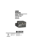
USER
MANUAL
Model 1000RP Series
AC and DC Rack Mount
Power Supplies
Part# 07M1000RP-B
Doc# 078011UB
Revised 3/19/96
SALES OFFICE
(301) 975-1000
TECHNICAL SUPPORT
(301) 975-1007
1.0 WARRANTY INFORMATION
2.0 GENERAL INFORMATION
Patton Electronics warrants all Model 1000RP Series
components to be free from defects, and will—at our option—repair or
replace the products should they fail within one year from the first date
of shipment. This warranty is limited to defects in workmanship or
materials, and does not cover customer damage, abuse or
unauthorized modification. If these products fail or do not perform as
warranted, your sole recourse shall be repair or replacement as
described above. Under no condition shall Patton Electronics be
liable for any damages incurred by the use of these products. These
damages include, but are not limited to, the following: lost profits, lost
savings and incidental or consequential damages arising from the use
of or inability to use this product. Patton Electronics specifically
disclaims all other warranties, expressed or implied, and the installation
or use of this product shall be deemed an acceptance of these terms by
the user.
Thank you for your purchase of these Patton Electronics products.
They have been thoroughly inspected and tested and are warranted for
One Year parts and labor. If any questions or problems arise during
installation or use of these products, please do not hesitate to contact
Patton Electronics Technical Support at (301) 975-1007.
1.1 RADIO AND TV INTERFERENCE
The Model 1000RP Series units generate and use radio frequency
energy, and if not installed and used properly—that is, in strict
accordance with the manufacturer's instructions—may cause
interference to radio and television reception. They have been tested
and found to comply with the limits for a Class A computing device in
accordance with the specifications in Subpart J of Part 15 of FCC rules,
which are designed to provide reasonable protection from such
interference in a commercial installation. However, there is no
guarantee that interference will not occur in a particular installation. If
these products do cause interference to radio or television reception,
which can be determined by turning off the unit, the user is encouraged
to try to correct the interference by one or more of the following
measures: moving the computing equipment away from the receiver,
re-orienting the receiving antenna and/or plugging the receiving
equipment into a different AC outlet (such that the computing
equipment and receiver are on different branches).
1.2 SERVICE
All warranty and non-warranty repairs must be returned freight
prepaid and insured to Patton Electronics. All returns must have a
Return Materials Authorization number on the outside of the shipping
container. This number may be obtained from Patton Electronics
Technical Service at (301) 975-1007. Packages received without an
RMA number will not be accepted. Patton's technical staff is also
available to answer any questions that might arise concerning the
installation or use of your products. Technical Service hours: 8AM to
5PM EST, Monday through Friday.
1
2.1 FEATURES
• Low Profile “Mid-Plane Architecture” Design
• Easily Replaceable Front and Rear Modules
• Front Panel Power Switch and LED Indicator(s)
• Compatible with all Patton Rack Cards
• Compatible with Patton Rack Chassis and Cluster Boxes
• One Power Supply Services up to 16 Rack Cards
• AC Models Available in Domestic/International 120/230V AC and
European (EN60950 Compliant) 120/230V AC Versions
• DC Models Available with 48V, 24V and 12V DC Power Input
2.2 DESCRIPTION
The Patton Model 1000RP Series power supply modules fit in any
Patton rack chassis or Cluster Box, and supply up to sixteen Patton
rack cards with necessary operating power. Like all Patton rack cards,
the Model 1000RP Series uses a mid-plane architecture: Each module
incorporates a front power supply module (with power switch and LEDs)
and rear power entry module (with power source interface).
The Model 1000RP Series is compatible with all Patton Rack
Cards, and is available with an AC or a DC input. There are two
different AC versions available: The first version is CSA and UL (or
equivalent) certified. The second version adds elements that allow it to
comply with the EN 60950 Safety of Information Technology Equipment
standard. Both AC power supplies accept 120 or 220-240V AC.
The 48V DC power module accepts an input voltage of 40-60V
DC. The 24V DC power module accepts an input voltage of 18-36V
DC. The 12V DC power module accepts an input voltage of
10-20V DC. All DC modules use cage clamp terminal blocks that make
wire connection easy. An extra port on the terminal block allows the
user to daisy chain multiple units together. An alarm relay opens when
power is attached and closes when power is disconnected.
2
3.0 INSTALLATION
Caution: To avoid shock hazard, do not connect AC
or DC power cable(s) until power supply module is fully
assembled.
Patton’s Model 1000RP Series power supply modules are easy to
install and require no configuration. This section describes the
functions of the Model 1000R16P rack chassis, tells how to install front
and rear power supply cards into the chassis and how to make the
power interface connections.
Front (Power Supply) Card Installation
3.1 THE MODEL 1000R16P RACK CHASSIS
1.
Make sure the power switch is in the OFF position.
The Model 1000R16P Rack Chassis (Figure 1, below) features
sixteen function card slots and one power supply card slot. (Note: refer
to function card user manuals for proper installation of function cards)
Measuring only 3.5” high, the Model 1000R16P is designed to occupy
only 2U in a 19” rack. Sturdy front handles allow the Model 1000R16P
to be extracted and transported conveniently.
2.
Slide the power supply card into the front of the chassis. It should
meet the rear card when it's almost all the way into the chassis.
3.
Push the front card gently into the multipin connector on the
rear card.
4.
Secure the front card using the thumb screws.
3.3 REAR CARD POWER CONNECTION - AC VERSIONS
The Model 1000RPEM and 1000RPEM-V rear cards are equipped
with a shrouded male IEC-320 AC power interface. This interface
accepts a domestic US power cord (supplied) or any number of
international power cords (see Appendix B).
3.4 REAR CARD POWER CONNECTION - DC VERSION
Figure 1. Model 1000R16P Rack Chassis with Power Supply
3.2 INSTALLING POWER SUPPLY MODULES
The Model 1000RPEM-DC rear card comes equipped with a cage
clamp terminal block. The following instructions will tell you how to
install the rear card.
All power supply modules (AC or DC) are comprised of two cards:
the front power supply card and the rear power entry card. These two
cards meet inside the rack chassis and plug into each other by means
of a multipin connector. (The same holds true for all Patton Cluster
Boxes as well.) Use the following steps as a guideline for installing
each power supply module into the Model 1000R16P rack chassis:
Rear (Power Entry) Card Installation
1.
Attach the ground wire using the star washer and the #6-32 nut.
Use a wrench to tighten the nut securely.
2.
Slide the power entry card into the back of the chassis along the
metal guide rails provided.
3.
Secure the rear card using the #4-40 metal screws provided.
3
Caution:
Connect the equipment to a SELV DC
supply source that is electrically isolated from the AC
power sources. The DC power source should also be
reliably connected to earth ground.
1.
Strip back the insulation on each of the wires .25”.
(continued)
4
4.0 OPERATION
2.
Use a small flat blade screwdriver to open the cage clamp as
shown in Figure 2 (below.). Insert the stripped portion of the wire
into the opening and remove the screwdriver. The cage clamp will
clamp the wire producing a reliable connection. Make sure all
strands of wire are captured and that there is no exposed wire.
Once the Model 1000RP Series power supply module is properly
installed, you are ready to operate the unit. Figure 3 (below) shows the
location of the power switch and LED indicators on the AC and DC
power supply module front cards.
Figure 2. Connecting bare wires to the Model 1000RPEM-DC power entry card.
3.
Connect the earth ground wire to the frame ground terminal.
4.
Connect the +VDC power wire to the +DC In terminal. Connect the
-VDC power wire to the -DC In terminal. The power supply card is
protected against accidental reversal of polarity. If the DC-Input
LED does not light, check the polarity of the input wiring.
5.
Connect the Alarm contacts as needed by your application.
Figure 3 The power switch and front panel LEDs on the AC and DC front card.
4.1 FRONT PANEL SWITCH
The power supply on/off switch is located on the front panel. The
power supply may be switched off at any time without harming the
installed cards (Note: The switch should be in the OFF position before
installing or removing either the front or the rear power supply card).
4.2 LED STATUS MONITOR(S)
The AC modules in the Model 1000RP Series incorporate a single
“Power” LED, which lights when the power switch is turned on and the
unit is connected to an AC power source.
The DC Modules in the Model 1000RP Series feature two front
panel LEDs that indicate the condition of the power line. The “Power”
LED will only light when the power switch is turned on and low voltage
AC power is available to the function cards installed in the rack. The
“DC Input” LED will light whenever a power source is present (with
correct polarity), regardless of whether or not the power switch is
turned on.
5
6
5.0 SERVICE PROCEDURES
This section describes the procedures for Power Line Voltage
Settings and Fuse Replacement for Patton Models 1000RPSM-2,
1000RPEM, 1000RPSM-V and 1000RPEM-V. Note: These procedures apply
generally to all products listed above, which (products) will henceforth
be referred to as “the unit”.
WARNING!
To avoid electric shock, always remove
AC power cord before servicing front or rear card of
power supply module.
5.1 PROCEDURE FOR POWER LINE VOLTAGE SETTING:
MODELS 1000RPSM-2 AND 1000RPSM-V
WARNING! When you change the voltage setting,
you must also replace the fuse according to the
instructions in Section 5.2
Although the Models 1000RPSM-2 and 1000RPSM-V are shipped
from the factory with a customer-specified power supply configuration,
you may change the configuration yourself. Here are the steps to switch
the configuration of the power supply between 120 and
220 - 240 volts AC:
1.
Switch the unit OFF.
2.
Remove the power plug from the AC wall outlet.
3.
Remove the power plug out of the rear of the unit.
4.
Switch the unit ON and verify that the front panel “Power” LED is
not lit. Switch the unit OFF.
5.
Remove the front power supply card and locate the two position
switch near the back of the card. Slide the switch to the desired
voltage (Note: The actual values on the switch may be "110/220",
"115/230", or a similar indication).
6.
Replace the existing fuse with one of the correct value (see
Section 5.2 for fuse replacement procedure and Appendix B for
the appropriate fuse).
7.
Replace the front card.
8.
Replace the power supply cord, if necessary (see Appendix B for
the appropriate power cord).
5.2 PROCEDURE FOR FUSE REPLACEMENT:
MODELS 1000RPEM AND 1000RPEM-V
Steps 1 - 5 in the instructions below apply to both models. Steps 6
- 10 are different for the Model1000RPEM than for the Model
1000RPEM-V.
(Steps #1- 5 for both models)
1.
Switch the front card OFF.
2.
Remove the power plug from the AC wall outlet.
3.
Remove the power plug out of the rear of the unit.
4.
Switch the unit ON and verify that the front panel “Power” LED is
not lit. Switch the unit OFF.
5. DETERMINE THAT THE LINE VOLTAGE IS WITHIN THE
PROPER VOLTAGE RANGE SPECIFIED FOR THE UNIT. (A
RANGE OF 100 TO 130 VAC IS PERMISSIBLE FOR THE 120
VOLT SETTING. A RANGE OF 200 TO 240 VAC IS
PERMISSIBLE FOR THE 220 VOLT SETTING.) IMPROPER
VOLTAGE SETTING WILL RESULT IN DAMAGE, IMPROPER
FUNCTIONING, OR BOTH. Improper voltage setting is also the
leading cause for a blown fuse. If the voltage setting switch was
incorrectly set, see Section 5.1 for the instructions for proper
setting of the power line voltage selector switch and continue from
there.
(Steps #6 - 9 for Model 1000RPEM)
6.
WARNING! Replace the fuse only with one that has
the correct voltage and current rating for the voltage
setting of the unit (the proper fuse ratings will be marked
on the rear panel of the unit*). Replacing the fuse with
one having an incorrect rating can result in a fire!
7.
7
Using a small screwdriver, pop the compartment open: It will slide
open like a drawer. Depending upon the exact part used, the
drawer may slide completely out of the fuse holder or it may stop
part way out. Note that there are two fuses in the drawer: The
front fuse is the spare, the rear fuse is the "active" fuse.
If the active fuse appears to be blown, remove it from the clips and
replace it with the spare from the front compartment. Note the size
and rating of the blown fuse before discarding (*120V = TO.4;
240V = TO.2).
(continued)
8
8.
Replace the spare fuse with one of the appropriate size and rating
and close the drawer.
9.
Re-install the power cord.
1000RPSM-2 and 1000RPSM-V (AC Front Cards):
Power Supply: 120V AC or 220-24V AC, switchable
(Step #6- 9 for Model 1000RPEM-V)
6.
Using a small screwdriver, push in lightly and turn counter
clockwise to open the compartment. The top will pop open with the
fuse attached.
WARNING! Replace the fuse only with one that has
the correct voltage and current rating for the voltage
setting of the unit (the proper fuse ratings will be marked
on the rear panel of the unit*). Replacing the fuse with
one having an incorrect rating can result in a fire!
Maximum Input Current: “120V AC” setting: 400mA; “220V AC”
setting: 200mA
Output Voltage: 10V AC @ 2.4 A
If the active fuse appears to be blown, remove it from the front
container. Note the size and rating of the blown fuse before
discarding (*120V = TO.4; 240V = TO.2).
9.
Input Voltage: “120V AC” setting: 100-130V AC; “220V AC” setting:
200-240V AC
Isolation Voltage: Model 1000RPSM-2: 1.5 kV AC;
Model 1000RPSM-V: 5 kV AC
7.
8.
APPENDIX A
SPECIFICATIONS
Output Power: 24VA
Switches: Power on/off
LED Indicator: Power
Replace the spare fuse with one of the appropriate size and rating
and close the compartment.
1000RPEM and 1000RPEM-V (AC Rear Cards):
Re-install the power cord.
Connection: IEC-320 Shrouded Male
Fuse: 120V AC: 5x20mm, 400mA, Time-Delay; 240V AC: 5x20mm,
200mA, Time-Delay
9
10
APPENDIX B
FACTORY REPLACEMENT PARTS
AND ACCESSORIES
(APPENDIX A - Continued)
1000RPSM-48A/24A/12A (DC Front Card):
Power Supply: 48V DC (-48A version); 24V DC (-24A version);
DC (-12A version)
12V
Input Voltage: 40-60V DC (-48A version); 18-36V DC (-24A version);
10-20V DC (-12A version)
Input Protection: Surge protection via Silicon Avalanche Diode,
triggered at 75V DC (-48A version); 39V DC (-24A version);
22V DC (-12A version)
Patton Model #
Description
0821R4............................Fuse 5x20mm, 400mA, Time-Delay
Little Fuse P/N 218.400
Use for 120V applications
0821R2............................Fuse 5x20mm, 200mA, Time-Delay
Little Fuse P/N 218.200
Use for 240V applications
Maximum Input Current: 1A @ 40V DC (-48A version);
2A @ 18V DC (-24A version); 4A @ 10V DC (-12A version)
Isolation Voltage: 500V RMS, input to output (all models)
Output Voltage: 12V AC @ 2A
Output Power: 24W
Switches: Power on/off
LED Indicators: Power, DC Input
0805US ...........................American Power Cord
0805EUR.........................European Power Cord CEE 7
0805EURP ......................Europlug Power Cord CEE 7/16
0805UK ...........................United Kingdom Power Cord
0805AUS .........................Australia/New Zealand Power Cord
0805DEN.........................Denmark Power Cord
0805FR............................France/Belgium Power Cord
0805IN.............................India Power Cord
0805IS .............................Israel Power Cord
0805JAP ..........................Japan Power Cord
0805SW...........................Switzerland Power Cord
1000RPEM-DC (DC Rear Card):
Connection: Cage-clamp terminal block with:
+DC In
-DC In
Frame Ground
Alarm
Alarm C
+DC Out
-DC Out
Wire: 26-14 solid or stranded cable
Alarm: Opens when power is attached and closes when power is
disconnected
11
12