1
COMSPHERE
3550 SERIES DATA SERVICE
UNITS MODELS 3550 AND 3551
USER’S GUIDE
Document No. 3550-A2-GB20-20
December 1996
COMSPHERE 3550 Series Data Service Units
COMSPHERE
Model 3550 and 3551
Data Service Units
User’s Guide
3550-A2-GB20-20
3rd Edition (December 1996)
Changes and enhancements to the product and to the information herein will be documented and issued as a new release.
United States
FCC Registration number: AW292J-61661-DD-N
PSTN Ringer Equivalence number (REN): DBM option 0.7B
Canada
V.32 Dial Backup Module
Certification number: 230 3684 A
DOC Load number: 7
Warranty, Sales, and Service Information
Contact your sales or service representative directly for any help needed. For additional information concerning warranty,
sales, service, repair, installation, documentation, or training, use one of the following methods:
• Via the Internet: Visit the Paradyne World Wide Web site at http://www.paradyne.com
• Via Telephone: Call our automated call system to receive current information via fax or to speak with a company
representative.
— Within the U.S.A., call 1-800-870-2221
— International, call 727-530-2340
Trademarks
All products and services mentioned herein are the trademarks, service marks, registered trademarks or registered service
marks of their respective owners.
Printed on recycled paper
COPYRIGHT 1996 Paradyne Corporation. All rights reserved.
This publication is protected by federal copyright law. No part of this publication may be copied or distributed, transmitted, transcribed, stored in a retrieval system,
or translated into any human or computer language in any form or by any means, electronic, mechanical, magnetic, manual or otherwise, or disclosed to third parties
without the express written permission of Paradyne Corporation, 8545 126th Avenue North, P.O. Box 2826, Largo, Florida 33779-2826.
Paradyne Corporation makes no representation or warranties with respect to the contents hereof and specifically disclaims any implied warranties of merchantability
or fitness for a particular purpose. Further, Paradyne Corporation reserves the right to revise this publication and to make changes from time to time in the contents
hereof without obligation of Paradyne Corporation to notify any person of such revision or changes.
A
December 1996
3550-A2-GB20-20
Safety Instructions
Important Safety Instructions
1.
Read and follow all warning notices and instructions marked on the product or
included in the manual.
2.
This product is intended to be used with a three-wire grounding type plug – a plug
which has a grounding pin. This is a safety feature. Equipment grounding is vital to
ensure safe operation. Do not defeat the purpose of the grounding type plug by
modifying the plug or using an adaptor.
Prior to installation, use an outlet tester or a voltmeter to check the ac receptacle for
the presence of earth ground. If the receptacle is not properly grounded, the
installation must not continue until a qualified electrician has corrected the problem.
If a three-wire grounding type power source is not available, consult a qualified
electrician to determine another method of grounding the equipment.
3.
Slots and openings in the cabinet are provided for ventilation. To ensure reliable
operation of the product and to protect it from overheating, these slots and openings
must not be blocked or covered.
4.
Do not allow anything to rest on the power cord and do not locate the product where
persons will walk on the power cord.
5.
Do not attempt to service this product yourself, as opening or removing covers may
expose you to dangerous high voltage points or other risks. Refer all servicing to
qualified service personnel.
6.
General purpose cables are provided with this product. Special cables, which may be
required by the regulatory inspection authority for the installation site, are the
responsibility of the customer.
7.
When installed in the final configuration, the product must comply with the applicable
Safety Standards and regulatory requirements of the country in which it is installed. If
necessary, consult with the appropriate regulatory agencies and inspection
authorities to ensure compliance.
8.
A rare phenomenon can create a voltage potential between the earth grounds of two
or more buildings. If products installed in separate buildings are interconnected, the
voltage potential may cause a hazardous condition. Consult a qualified electrical
consultant to determine whether or not this phenomenon exists and, if necessary,
implement corrective action prior to interconnecting the products.
In addition, if the equipment is to be used with telecommunications circuits, take the
following precautions:
–
–
–
–
–
–
3550-A2-GB20-20
Never install telephone wiring during a lightning storm.
Never install telephone jacks in wet locations unless the jack is specifically designed
for wet locations.
Never touch uninsulated telephone wires or terminals unless the telephone line has
been disconnected at the network interface.
Use caution when installing or modifying telephone lines.
Avoid using a telephone (other than a cordless type) during an electrical storm.
There may be a remote risk of electric shock from lightning.
Do not use the telephone to report a gas leak in the vicinity of the leak.
December 1996
B
COMSPHERE 3550 Series Data Service Units
Notices
C
December 1996
3550-A2-GB20-20
Safety Instructions
Government Requirements
The Federal Communications Commission (FCC) requires that instructions pertaining to
connection to the telephone network be included in the installation and operation manual. Specific
instructions are listed in this section.
Notice to Users of the Digital Data Service
This equipment complies with Part 68 of the FCC rules. On the bottom of the equipment is a label
or silk-screened text that contains, among other information, the FCC registration number and
Ringer Equivalence Number (REN) for this equipment. If requested, please provide this
information to your telephone company.
The REN is useful to determine the quantity of devices you may connect to your telephone line
and still have all of those devices ring when your number is called. In most, but not all areas, the
sum of the RENs of all devices should not exceed 5. To be certain of the number of devices you
may connect to your line, as determined by the REN, you should call your local telephone
company to ascertain the maximum REN for your calling area.
If your DSU causes harm to the telephone network, the telephone company may discontinue your
service temporarily. If possible, they will notify you in advance. But if advance notice is not
practical, you will be notified as soon as possible. You will be advised of your right to file a
complaint with the FCC.
Your telephone company may make changes in its facilities, equipment, operations, or procedures
that could affect the proper operation of your equipment. If so, you will be given advance notice so
as to give you an opportunity to maintain uninterrupted service.
The DBM cannot be used on public coin-operated telephone service provided by the telephone
company. Connection to party-line service is subject to state tariffs. (Contact the state public utility
commission, public service commission, or corporation commission for information.)
No repairs may be performed by the user. Should you experience difficulty with this equipment,
refer to the Equipment Warranty and Support section of Chapter 1.
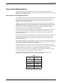
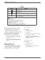
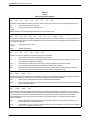
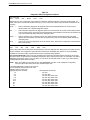
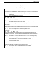
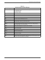
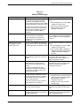
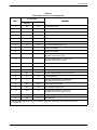
For Digital Data Service (DDS) installations, inform the local telephone company of the
appropriate network channel interface code for the service you desire.
DDS
3550-A2-GB20-20
Interface
Code
Data Rate
(bps)
04DU5-24
2400
04DU5-48
4800
04DU5-96
9600
04DU5-19
19,200
04DU5-56
56,000
December 1996
D
COMSPHERE 3550 Series Data Service Units
The DDS Service Order Number is 6.0Y. The jack configurations required are RJ48S for the
Model 3550 DSU and RJ48T for the Model 3551. With an RJ48T configuration, you must specify
the number of data lines you require. Refer to the Technical Specifications section of Chapter 1 for
V.32 DBM jack information.
After the telephone company has installed the requested jack, you can connect the DSU with the
appropriate cable (provided). An FCC-compliant telephone cord and modular plug is provided
with this equipment. This equipment is designed to be connected to the telephone network or
premises wiring using a compatible modular jack that is Part 68 compliant.
E
December 1996
3550-A2-GB20-20
Table of Contents
Preface
About This Guide . . . . . . . . . . . . . . . . . . . . . . . . . . . . . . . . . . . . . . . . . .
How to Use This Guide . . . . . . . . . . . . . . . . . . . . . . . . . . . . . . . . . . . . .
Related Documents . . . . . . . . . . . . . . . . . . . . . . . . . . . . . . . . . . . . . . . .
Reference Documents . . . . . . . . . . . . . . . . . . . . . . . . . . . . . . . . . . . . . .
vii
vii
viii
viii
1. About Your DSU
Overview . . . . . . . . . . . . . . . . . . . . . . . . . . . . . . . . . . . . . . . . . . . . . . . .
Standard Features . . . . . . . . . . . . . . . . . . . . . . . . . . . . . . . . . . . . . . . . . .
Optional Features . . . . . . . . . . . . . . . . . . . . . . . . . . . . . . . . . . . . . . . . . .
Upgrades Available . . . . . . . . . . . . . . . . . . . . . . . . . . . . . . . . . . . . . . . .
Technical Specifications . . . . . . . . . . . . . . . . . . . . . . . . . . . . . . . . . . . .
Equipment Warranty and Support . . . . . . . . . . . . . . . . . . . . . . . . . . . . .
1-1
1-1
1-2
1-3
1-3
1-8
2. Installing the Model 3550 DSU
Overview . . . . . . . . . . . . . . . . . . . . . . . . . . . . . . . . . . . . . . . . . . . . . . . .
Before You Begin . . . . . . . . . . . . . . . . . . . . . . . . . . . . . . . . . . . . . . . . . .
How to Change Hardware Straps . . . . . . . . . . . . . . . . . . . . . . . . . . . . . .
Where to Place the DSU . . . . . . . . . . . . . . . . . . . . . . . . . . . . . . . . . . . .
Installing the DSU . . . . . . . . . . . . . . . . . . . . . . . . . . . . . . . . . . . . . . . . .
Connecting to the Network . . . . . . . . . . . . . . . . . . . . . . . . . . . . . . . . . .
Addressing the Unit . . . . . . . . . . . . . . . . . . . . . . . . . . . . . . . . . . . . . . . .
Connecting the DSU to a DTE . . . . . . . . . . . . . . . . . . . . . . . . . . . . . . . .
Verifying Operation and Testing Connections . . . . . . . . . . . . . . . . . . . .
2-1
2-1
2-2
2-4
2-4
2-5
2-8
2-10
2-11
3. Installing the Model 3551 DSU
Overview . . . . . . . . . . . . . . . . . . . . . . . . . . . . . . . . . . . . . . . . . . . . . . . .
Before You Begin . . . . . . . . . . . . . . . . . . . . . . . . . . . . . . . . . . . . . . . . . .
How to Change Hardware Straps . . . . . . . . . . . . . . . . . . . . . . . . . . . . . .
Installing the DSU . . . . . . . . . . . . . . . . . . . . . . . . . . . . . . . . . . . . . . . . .
Connecting to the Network . . . . . . . . . . . . . . . . . . . . . . . . . . . . . . . . . .
Connecting the DSU to a DTE . . . . . . . . . . . . . . . . . . . . . . . . . . . . . . . .
Addressing the Unit . . . . . . . . . . . . . . . . . . . . . . . . . . . . . . . . . . . . . . . .
Verifying Operation and Testing Connections . . . . . . . . . . . . . . . . . . . .
3550-A2-GB20-20
December 1996
3-1
3-2
3-2
3-5
3-8
3-9
3-9
3-10
i
COMSPHERE 3550 Series Data Service Units
4. Operating the DSU
Overview . . . . . . . . . . . . . . . . . . . . . . . . . . . . . . . . . . . . . . . . . . . . . . . .
DCP and SDCP Operation . . . . . . . . . . . . . . . . . . . . . . . . . . . . . . . . . . .
Menu Structure . . . . . . . . . . . . . . . . . . . . . . . . . . . . . . . . . . . . . . . . . . . .
Status Branch . . . . . . . . . . . . . . . . . . . . . . . . . . . . . . . . . . . . . . . . . . . . .
Backup Branch . . . . . . . . . . . . . . . . . . . . . . . . . . . . . . . . . . . . . . . . . . . .
Test Branch . . . . . . . . . . . . . . . . . . . . . . . . . . . . . . . . . . . . . . . . . . . . . .
Configuration Branch . . . . . . . . . . . . . . . . . . . . . . . . . . . . . . . . . . . . . . .
Control Branch . . . . . . . . . . . . . . . . . . . . . . . . . . . . . . . . . . . . . . . . . . . .
Messages Branch . . . . . . . . . . . . . . . . . . . . . . . . . . . . . . . . . . . . . . . . . .
4-2
4-2
4-4
4-4
4-6
4-9
4-12
4-19
4-20
5. Configuring the Unit
Overview . . . . . . . . . . . . . . . . . . . . . . . . . . . . . . . . . . . . . . . . . . . . . . . . 5-1
Using the DCP to Set Configuration Options . . . . . . . . . . . . . . . . . . . . 5-2
Configuration Option Tables . . . . . . . . . . . . . . . . . . . . . . . . . . . . . . . . . 5-5
Appendix
A.
B.
C.
D.
E.
F.
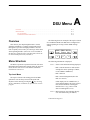
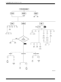
DSU Menu . . . . . . . . . . . . . . . . . . . . . . . . . . . . . . . . . . . . . . . . . . .
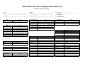
Configuration Worksheets . . . . . . . . . . . . . . . . . . . . . . . . . . . . . . .
Status Indicators and Control Panel Messages . . . . . . . . . . . . . . .
Pin Assignments . . . . . . . . . . . . . . . . . . . . . . . . . . . . . . . . . . . . . . .
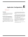
Application Configurations . . . . . . . . . . . . . . . . . . . . . . . . . . . . . .
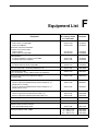
Equipment List . . . . . . . . . . . . . . . . . . . . . . . . . . . . . . . . . . . . . . . .
A-1
B- 1
C- 1
D-1
E -1
F -1
Glossary
Index
ii
December 1996
3550-A2-GB20-20
Table of Contents
List of Figures
Figure
Page
2-1
2-2
2-3
2-4
2-5
2-6
2-7
3-1
3-2
3-3
3-4
3-5
4-1
4-2
4-3
D-1
D-2
D-3
2-3
2-4
2-6
2-6
2-7
2-9
2-10
3-3
3-5
3-6
3-7
3-10
4-2
4-3
4-9
D-1
D-2
D-4
D-5
D-6
E-1
E-2
3550-A2-GB20-20
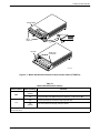
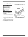
Model 3550 Hardware Switch Location (shown without a TDM/Flex) . . . . . . . . . .
Model 3550 Electrical Connection . . . . . . . . . . . . . . . . . . . . . . . . . . . . . . . . . . . . . .
Model 3550 DSU NMS Connection . . . . . . . . . . . . . . . . . . . . . . . . . . . . . . . . . . . . .
Model 3550 DSU Dial (PSTN) Network Connection . . . . . . . . . . . . . . . . . . . . . . . .
Model 3550 DSU DDS (LADS) Network Connection . . . . . . . . . . . . . . . . . . . . . . .
Addressing Example . . . . . . . . . . . . . . . . . . . . . . . . . . . . . . . . . . . . . . . . . . . . . . . . .
Installing Cables . . . . . . . . . . . . . . . . . . . . . . . . . . . . . . . . . . . . . . . . . . . . . . . . . . . . .
Model 3551 DSU Switch and Jumper Locations . . . . . . . . . . . . . . . . . . . . . . . . . . . .
COMSPHERE 3000 Series Carrier, Rear View . . . . . . . . . . . . . . . . . . . . . . . . . . . . .
Model 3551 DSU Installation and Circuit Pack Lock . . . . . . . . . . . . . . . . . . . . . . . .
Model DSU V.35 Interconnect Cable Installation . . . . . . . . . . . . . . . . . . . . . . . . . . .
Addressing Example . . . . . . . . . . . . . . . . . . . . . . . . . . . . . . . . . . . . . . . . . . . . . . . . .
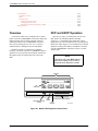
Model 3550 Diagnostic Control Panel . . . . . . . . . . . . . . . . . . . . . . . . . . . . . . . . . . . .
SDCP and Model 3551 DSU Faceplate . . . . . . . . . . . . . . . . . . . . . . . . . . . . . . . . . . .
Loopbacks . . . . . . . . . . . . . . . . . . . . . . . . . . . . . . . . . . . . . . . . . . . . . . . . . . . . . . . . .
Digital Network Connector . . . . . . . . . . . . . . . . . . . . . . . . . . . . . . . . . . . . . . . . . . . .
3600 Hubbing Device (3600-F3-300) . . . . . . . . . . . . . . . . . . . . . . . . . . . . . . . . . . . .
Model 3551 DSU 25-Pin EIA-232/25-Pin V.35
Rear Connector Plate (3000-F1-021) . . . . . . . . . . . . . . . . . . . . . . . . . . . . . . . . . . .
V.35 Interconnect Cable (3000-F1-510) . . . . . . . . . . . . . . . . . . . . . . . . . . . . . . . . . .
EIA-232-D Crossover Cable (4951-035F) . . . . . . . . . . . . . . . . . . . . . . . . . . . . . . . . .
V.35 Crossover Cable (3211-178F) . . . . . . . . . . . . . . . . . . . . . . . . . . . . . . . . . . . . . .
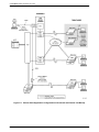
Point-to-Point Application Configurations with Internal and
External V.32 Backup . . . . . . . . . . . . . . . . . . . . . . . . . . . . . . . . . . . . . . . . . . . . . .
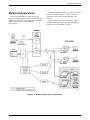
Multipoint Application Configurations . . . . . . . . . . . . . . . . . . . . . . . . . . . . . . . . . . .
December 1996
D-4
D-6
D-8
D-9
E-2
E-3
iii
COMSPHERE 3550 Series Data Service Units
List of Tables
Table
1-1
1-2
1-3
1-4
2-1
2-2
3-1
3-2
4-1
4-2
4-3
4-4
4-5
4-6
4-7
5-1
5-2
5-3
5-4
5-5
5-6
5-7
5-8
5-9
5-10
5-11
5-12
5-13
5-14
iv
Page
General Technical Specifications . . . . . . . . . . . . . . . . . . . . . . . . . . . . . . . . . . . . . . . .
DSU Technical Specifications . . . . . . . . . . . . . . . . . . . . . . . . . . . . . . . . . . . . . . . . . .
V.32 DBM Technical Specifications . . . . . . . . . . . . . . . . . . . . . . . . . . . . . . . . . . . . .
2-Port TDM/Flex Technical Specifications . . . . . . . . . . . . . . . . . . . . . . . . . . . . . . . .
Model 3550 DSU Switch Settings . . . . . . . . . . . . . . . . . . . . . . . . . . . . . . . . . . . . . . .
LADS Connection Distances . . . . . . . . . . . . . . . . . . . . . . . . . . . . . . . . . . . . . . . . . . .
Model 3551 DSU Switch Settings . . . . . . . . . . . . . . . . . . . . . . . . . . . . . . . . . . . . . . .
Model 3551 DSU Jumper Straps . . . . . . . . . . . . . . . . . . . . . . . . . . . . . . . . . . . . . . . .
Identity Descriptions . . . . . . . . . . . . . . . . . . . . . . . . . . . . . . . . . . . . . . . . . . . . . . . . .
Backup Branch Menu Selections . . . . . . . . . . . . . . . . . . . . . . . . . . . . . . . . . . . . . . . .
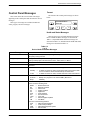
Digital Test Results . . . . . . . . . . . . . . . . . . . . . . . . . . . . . . . . . . . . . . . . . . . . . . . . . .
End-to-End Test Results . . . . . . . . . . . . . . . . . . . . . . . . . . . . . . . . . . . . . . . . . . . . . .
Bit Error Rate Test Results . . . . . . . . . . . . . . . . . . . . . . . . . . . . . . . . . . . . . . . . . . . .
Directory Entry and Password Characters . . . . . . . . . . . . . . . . . . . . . . . . . . . . . . . . .
Lead States . . . . . . . . . . . . . . . . . . . . . . . . . . . . . . . . . . . . . . . . . . . . . . . . . . . . . . . . .
DSU Configuration Options . . . . . . . . . . . . . . . . . . . . . . . . . . . . . . . . . . . . . . . . . . .
Diagnostic (DSU) Configuration Options . . . . . . . . . . . . . . . . . . . . . . . . . . . . . . . . .
Diagnostic (DBM) Configuration Options . . . . . . . . . . . . . . . . . . . . . . . . . . . . . . . .
Diagnostic (External DBU) Configuration Options . . . . . . . . . . . . . . . . . . . . . . . . .
Diagnostic (General) Configuration Options . . . . . . . . . . . . . . . . . . . . . . . . . . . . . . .
DBM Configuration Options . . . . . . . . . . . . . . . . . . . . . . . . . . . . . . . . . . . . . . . . . . .
External DBU Configuration Options . . . . . . . . . . . . . . . . . . . . . . . . . . . . . . . . . . . .
General Configuration Options . . . . . . . . . . . . . . . . . . . . . . . . . . . . . . . . . . . . . . . . .
Backup Configuration Options . . . . . . . . . . . . . . . . . . . . . . . . . . . . . . . . . . . . . . . . .
MUX (Setup) Configuration Options . . . . . . . . . . . . . . . . . . . . . . . . . . . . . . . . . . . .
MUX (Port) Configuration Options . . . . . . . . . . . . . . . . . . . . . . . . . . . . . . . . . . . . . .
Port Speed (DSU) Configuration Options . . . . . . . . . . . . . . . . . . . . . . . . . . . . . . . . .
Port Speed (DBM) Configuration Options . . . . . . . . . . . . . . . . . . . . . . . . . . . . . . . .
Port Speed (External DBU) Configuration Options . . . . . . . . . . . . . . . . . . . . . . . . .
December 1996
1-4
1-6
1-7
1-8
2-3
2-7
3-3
3-4
4-6
4-8
4-11
4-11
4-12
4-18
4-20
5-6
5-8
5-9
5-10
5-10
5-12
5-16
5-17
5-21
5-23
5-23
5-27
5-28
5-29
3550-A2-GB20-20
Table of Contents
Table
C-1
C-2
C-3
C-4
C-5
C-6
C-7
C-8
C-9
C-10
D-1
D-2
D-3
D-4
D-5
D-6
3550-A2-GB20-20
Page
DSU Status Indicators . . . . . . . . . . . . . . . . . . . . . . . . . . . . . . . . . . . . . . . . . . . . . . . .
SDCP Status Indicators . . . . . . . . . . . . . . . . . . . . . . . . . . . . . . . . . . . . . . . . . . . . . . .
Device Health and Status Messages . . . . . . . . . . . . . . . . . . . . . . . . . . . . . . . . . . . . . .
Expanded Health and Status Messages . . . . . . . . . . . . . . . . . . . . . . . . . . . . . . . . . . .
Subnetwork Health and Status Messages . . . . . . . . . . . . . . . . . . . . . . . . . . . . . . . . .
Command Progress Messages . . . . . . . . . . . . . . . . . . . . . . . . . . . . . . . . . . . . . . . . . .
Dial Backup Progress Messages . . . . . . . . . . . . . . . . . . . . . . . . . . . . . . . . . . . . . . . .
Command Error Messages . . . . . . . . . . . . . . . . . . . . . . . . . . . . . . . . . . . . . . . . . . . . .
Dial Backup Error Messages . . . . . . . . . . . . . . . . . . . . . . . . . . . . . . . . . . . . . . . . . . .
TDM/Flex Error Messages . . . . . . . . . . . . . . . . . . . . . . . . . . . . . . . . . . . . . . . . . . . .
Model 3550 – Digital (DDS) Network Connector Pin Assignments . . . . . . . . . . . . .
Model 3550 – Dial (Analog) Network Connector Pin Assignments . . . . . . . . . . . . .
3600 Hubbing Device Pin Assignments . . . . . . . . . . . . . . . . . . . . . . . . . . . . . . . . . .
3600 Hubbing Device CC IN/DC OUT Jack Pin Assignments . . . . . . . . . . . . . . . . .
EIA-232/V.24 Connector Pin Assignments . . . . . . . . . . . . . . . . . . . . . . . . . . . . . . . .
V.35 Connector Pin Assignments . . . . . . . . . . . . . . . . . . . . . . . . . . . . . . . . . . . . . . . .
December 1996
C-2
C-2
C-3
C-6
C-7
C-8
C-8
C-9
C-10
C-11
D-2
D-2
D-3
D-3
D-5
D-7
v
Preface
About This Guide
Chapter 3
Provides step-by-step instructions for
installing your carrier-mounted
Model 3551 DSU.
Chapter 4
Describes how to operate your DSU
and its DBM and TDM/Flex options.
Chapter 5
Presents the basics of setting and
changing configuration options, and
provides Configuration Option Set
Tables, which describe each
configuration option in an option set,
along with its possible settings.
Appendix A
Provides a diagram for navigating
the DSU’s menu structure.
Appendix B
Summarizes the configuration option
sets for you.
Appendix C
Lists the DSU’s status indicators, as
well as their messages, identifying
when they appear.
Two installation chapters are provided, one for the
Model 3550 DSU and one for the Model 3551 DSU.
Select the chapter that applies to your DSU.
Appendix D
Shows point-to-point and multipoint
application configurations and
network hookups.
Refer to the following chapters or appendices, as
needed.
Appendix E
Provides cable and connector pin
assignments.
Appendix F
Equipment List
This user’s guide provides the information needed to
install and operate your Model 3550 or 3551 data service
unit (DSU), which may or may not be equipped with a
dial backup module (DBM) or time division multiplexer
(TDM). If your DSU is not equipped with these options,
skip the information that pertains to them.
Be sure to read the safety and regulatory information at
the beginning of this guide.
It is assumed that you are familiar with the functional
operation of digital data communications equipment.
How to Use This Guide
This guide provides basic information about your DSU,
how to install it and verify that it is installed and operating
correctly, how to operate the unit and its options, and how
to configure it.
Chapter 1
Chapter 2
3550-A2-GB20-20
Provides a general overview of the
DSU and its options, information
about equipment upgrades and
conversions, and the unit’s technical
specifications. It also includes
equipment warranty information and
equipment return instructions.
Glossary
Reference Card
Provides step-by-step instructions for
installing your standalone
Model 3550 DSU.
December 1996
vii
COMSPHERE 3550 Series Data Service Units
Related Documents
Reference Documents
• AT&T Technical Reference 41458
Call your sales representative to order additional
product documentation.
• AT&T Technical Reference 61330
Other product documentation includes the following:
• AT&T Technical Reference 62310 – 1987
3000-A2-GA31
COMSPHERE 3000 Series
Carrier, Installation Manual
• Bell Canada DCTE Specifications
3000-A2-GB41
COMSPHERE –48 Vdc Central
Office Power Unit, Installation
Guide
6700-A2-GB41
6700-A2-GY31
viii
• Bell Communications Research Technical
Reference Publication 41028
• CCITT V.35 (ISO 2593)
COMSPHERE 6700 Series
Network Management System,
User’s Guide, Security Manager
Feature Supplement
• EIA-232-D/V.24 (ISO 2110)
COMSPHERE 6700 Series
Network Management System,
User’s Guide
• Pacific Bell PUB L-780035-PB/NB
• Integrated Network Corporation Compatibility
Bulletin CB-INC-101
• Pacific Bell PUB L-780036-PB/NB
December 1996
3550-A2-GB20-20
About Your DSU
Overview . . . . . . . . . . . . . . . . . . . . . . . . . . . . . . . . . . . . . . . . . . . . . . . . . . . . . . . . . . . . . . . . . . . . . . . . . .
Standard Features . . . . . . . . . . . . . . . . . . . . . . . . . . . . . . . . . . . . . . . . . . . . . . . . . . . . . . . . . . . . . . . . . . .
Optional Features . . . . . . . . . . . . . . . . . . . . . . . . . . . . . . . . . . . . . . . . . . . . . . . . . . . . . . . . . . . . . . . . . . .
V.32 DBM . . . . . . . . . . . . . . . . . . . . . . . . . . . . . . . . . . . . . . . . . . . . . . . . . . . . . . . . . . . . . . . . . . . . . .
2-Port TDM/Flex . . . . . . . . . . . . . . . . . . . . . . . . . . . . . . . . . . . . . . . . . . . . . . . . . . . . . . . . . . . . . . . .
Upgrades Available . . . . . . . . . . . . . . . . . . . . . . . . . . . . . . . . . . . . . . . . . . . . . . . . . . . . . . . . . . . . . . . . . .
Technical Specifications . . . . . . . . . . . . . . . . . . . . . . . . . . . . . . . . . . . . . . . . . . . . . . . . . . . . . . . . . . . . . .
Equipment Warranty and Support . . . . . . . . . . . . . . . . . . . . . . . . . . . . . . . . . . . . . . . . . . . . . . . . . . . . . . .
1-1
1-1
1-2
1-2
1-3
1-3
1-3
1-8
• Rate Adaption. With this feature, the DSU can
adapt its data rate to a low-speed application while
operating over the high-speed DDS circuit.
Overview
The Model 3550 or 3551 data service unit (DSU)
supports communication between computers and other
data processing devices by providing connections to
digital data service (DDS) transmission facilities. Both
point-to-point and multipoint configurations are
supported.
• LADS operation. The DSU can operate as a local
area data set (LADS) (sometimes called a
limited-distance modem, or LDM) at 2.4, 4.8, 9.6,
19.2, 38.4, 56, or 64 kbps.
The following sections describe the standard features
of the DSU, as well as the features of the options that may
have been ordered with your unit. The technical
specifications of the DSU and its orderable options are
near the end of the chapter.
Standard Features
The Model 3550 or 3551 DSU offers the following
features:
• Multispeed operation. The DSU operates at data
rates of 2.4, 4.8, 9.6, 19.2, 38.4, and 56 kbps
full-duplex over the digital data service (DDS)
network.
• Single-Port Async/Sync. The single-port
asynchronous-to-synchronous feature makes it
possible to send asynchronous data over the
synchronous network.
• Nondisruptive Diagnostics. When set up to use
nondisruptive diagnostics, the DSU sends
diagnostic data without interrupting or disrupting
customer data.
• NMS control. The DSU can be controlled by
COMSPHEREr 6700 Series NMS. The 6700
Series NMS operates using Advanced Diagnostic
protocol (ADp).
Two DTE connectors (interfaces) are provided for
Port 1: EIA-232-D and V.35. Use the EIA-232-D
connector for data rates up to and including
19.2 kbps; use the V.35 connector for higher rates.
3550-A2-GB20-20
1
December 1996
The Model 3550 DSU requires a hubbing device
for connection to the NMS; the Model 3551 DSU is
connected to the NMS through the shared
diagnostic unit (SDU) in the COMSPHERE
3000 Series Carrier.
1-1
COMSPHERE 3550 Series Data Service Units
• Diagnostic Control Panel control. The
Model 3550 DSU is controlled from its diagnostic
control panel (DCP). The diagnostic control panel
for the Model 3551 DSU, called a shared diagnostic
control panel (SDCP), is installed in the
3000 Series Carrier. Both control panels display
information about the DSU on a 2-line,
16-character liquid crystal display (LCD) and
through light-emitting diode (LED) status
indicators.
The Model 3550 DSU can be ordered with the
following optional features:
• V.32bis 14.4 kbps Dial Backup Module (DBM)
• Time Division Multiplexer (TDM/Flex)
The Model 3551 DSU can be ordered with a V.32bis
14.4 kbps DBM, or it can be used with an external DBU.
If your DSU is not equipped with these options, go to
the next section.
NOTE
Except where a distinction is
made, the term DCP refers to both
types of diagnostic control panels,
the DCP or the SDCP.
V.32 DBM
• Full tributary diagnostics. The DSU supports a
full complement of diagnostic tests and commands.
Diagnostics can be addressed to and sent to
tributaries from a 6700 Series NMS workstation or
from the DCP of a control DSU.
• External dial backup. The DSU can use an
external dial backup unit (DBU – e.g., a
3800 Series dial/lease modem) to provide backup.
This feature may be used in a point-to-point DSU
configuration and can be used with either a control
or tributary DSU.
For more information about the 3000 Series Carrier or
the SDCP, refer to the COMSPHERE 3000 Series Carrier,
Installation Manual. For more information about the
6700 Series NMS, refer to the COMSPHERE 6700 Series
Network Management System, User’s Guide. These are
identified in the Related Documents section of the
Preface, which also provides information on how to order
these documents.
1-2
Optional Features
The V.32bis 14.4 kbps dial backup module (referred to
as DBM throughout this guide) childboard is attached to
the DSU circuit card. The DBM provides the following
features:
• Multispeed point-to-point backup. The DBM
provides point-to-point service over the 2-wire dial
network. Backup rates available are 2.4, 4.8, 9.6,
12.0, and 14.4 kbps.
• Independent operation. Although the DBM is
installed on the DSU, the two are configured
separately and most tests can be run on either
independent of the other (e.g., you can run a test on
the DBM while a test is running on the DSU).
• Security. There are four levels of call setup
security: None, Password, Callback, and Alarm.
• Management control. Dial backup can be initiated
from a 6700 Series NMS, the DSU’s DCP, or it can
be initiated automatically by the DSU-DBM.
• Automatic setup and restoration. When
configured for automatic backup, the DSU-DBM
initiates dial backup when it detects a failure in the
network, then restores the data path to the DDS
circuit when the network returns to service.
December 1996
3550-A2-GB20-20
About Your DSU
2-Port TDM/Flex
The 2-port TDM/Flex is a separate circuit card that
attaches to the Model 3550 DSU. It allows independent
ports to share one standard digital point-to-point facility.
The 2-port TDM/Flex provides the following features:
• Port capacity. This feature permits the DSU to
operate as a digital sharing device and provides two
independent ports. Port 1 is on the DSU and Port 2
is on the 2-port TDM/Flex. Either port can operate
as an EIA-232 or V.35 interface.
• Multiplexing. With this option, time division
multiplexing can be performed using two
independent ports to share one standard DDS
point-to-point circuit.
• Line speeds. The TDM/Flex operates at all line
speeds supported by the DSU: 2.4, 4.8, 9.6, 19.2,
38.4, and 56 kbps. For LADS operation, 64 kbps is
also supported.
• Port speeds. Each port can be set to 1.2, 2.4, 4.8,
9.6, 14.4, 19.2, 48, 56, or 64 kbps. In 2-port
TDM/Flex applications, the sum of the port speeds
cannot exceed the line speed.
• Asynchronous operation. Although the DSU
provides synchronous transmission through the
DDS network, any port can be configured for
asynchronous operation. When the 2-port
TDM/Flex is installed, asynchronous-tosynchronous conversion can be performed.
Asynchronous data rates of 150, 300, 600, 1200,
and 1800 bps are supported, along with the
synchronous data rates.
• Switched-carrier emulation. In 2-port TDM/Flex
transmission, switched-carrier emulation is optional
for each port, for both the inbound (toward the
control DSU) and outbound (from the tributary
DSU) directions.
• NMS control. Control of a 3550 DSU with 2-port
TDM/Flex can be performed from a 6700 Series
NMS or the DSU’s DCP.
• Point-to-point backup. A 3550 DSU with 2-port
TDM/Flex can also have a DBM installed for
point-to-point dial backup. If backup is at a
different speed than the DSU’s speed, TDM/Flex
operation automatically changes to the lower
speed.
Upgrades Available
Although your DSU may not currently have a DBM or
2-port TDM/Flex installed, you can add these features at a
later time. Both the DBM and 2-port TDM/Flex features
are available as upgrades.
You can order the option you want and install it
yourself (referred to as a field installation). Refer to the
Equipment List in Appendix F for the feature number to
order.
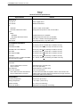
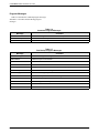
Technical Specifications
Tables 1-1 through 1-4 list the technical specifications
for the following:
• Digital sharing. With this feature, the ports can
share the same channel. All ports in a
digital-sharing group operate at the same speed, and
all receive the same data. When configured for
DSD (digital-sharing device) port contention, only
one port at a time is allowed to send.
• General specifications that apply to all Model 3550
and 3551 circuit cards (Table 1-1)
• Elastic store per port. A transmit elastic store
buffer is provided for each port for the support of
extended circuits. Both digital and analog
extensions are supported.
• Specifications for the 2-port TDM/Flex ć only used
with a Model 3550 (Table 1-4)
3550-A2-GB20-20
• Specifications for the Model 3550 and 3551 DSU
only (Table 1-2)
• Specifications for the V.32 DBM (Table 1-3)
December 1996
1-3
COMSPHERE 3550 Series Data Service Units
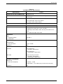
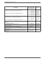
Table 1-1
(1 of 2)
General Technical Specifications
Specifications
Criteria
APPROVALS
FCC Part 15
Class A digital device
FCC Part 68
AW292J-61661-DD-N
UL
3550 DSU
3551 DSU, 3000 Series Carrier
Listed U L 1950, second edition
Recognized Component UL 1950, second edition
CSA
Safety
3550 DSU
3551 DSU, 3000 Series Carrier
Certified CSA 22.2, No. 950-M89
Certified Component CSA 22.2, No. 950-M89
Emissions
CSA 108.8 – M1983, Class A digital apparatus
Bell Canada
“DCTE Specifications,” July 1989, Issue 1
AC POWER REQUIREMENTS
3550 DSU
24 Vac (CT), 60 Hz +3 (0.093 amp, 5.8 watts at 115 Vac)
3550 DSU with DBM
24 Vac (CT), 60 HZ ± 3 (0.115 amp, 9.5 watts at 115 Vac)
3550 DSU with 2-Port TDM/Flex
24 Vac (CT), 60 Hz +3 (0.103 amp, 8.6 watts at 115 Vac)
3551 DSU
24 Vac (CT), 60 Hz +3 (0.029 amp, 4.5 watts at 115 Vac)
3551 DSU with DBM
24 Vac (CT), 60 Hz +3 (0.080 amp, 8.0 watts at 115 Vac)
V.32 DBM
24 Vac (CT), 60 Hz +3 (0.024 amp, 2.0 watts at 115 Vac)
3000 Series Carrier (16 DSUs with DBMs
plus SDU and fan module)
90 —132 Vac, 60 Hz +3 (1.650 amp, 165 watts at 115 Vac)
DTE INTERFACE
3550 DSU
25-pin D-subminiature connector
34-pin connector
3551 DSU with
25-Pin V.35 Interface
Uses a Rear Connector Plate with two
25-pin D-subminiature connectors.
EIA-232-D/CCITT V.24 (ISO 2110)
CCITT V.35 (ISO 2593)
EIA-232-D/CCITT V.24 (ISO 2110)
CCITT V.35 (ISO 2593)
(A V.35 Interconnect Cable is required to use the V.35 connector. The
cable provides an interface between the DSU’s 25-pin D-type connector
and the DTE cable’s V.35 connector.)
ENVIRONMENT
Operating Temperature
32° to 122° F (0° to 50° C)
Storage Temperature
– 4° to 158° F (–20° to 70° C)
Relative Humidity
5% — 95% (noncondensing)
Shock and Vibration
Withstands normal shipping and handling
1-4
December 1996
3550-A2-GB20-20
About Your DSU
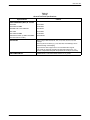
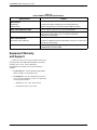
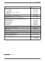
Table 1-1
(2 of 2)
General Technical Specifications
Specifications
Criteria
HEAT DISSIPATION (MAX.) AT 115 VAC
3550 DSU
22.16 Btu/hr
3550 DSU with DBM
29.00 Btu/hr
3550 DSU with 2-Port TDM/Flex
29.21 Btu/hr
3551 DSU
22.16 Btu/hr
3551 DSU with DBM
27.30 Btu/hr
3000 Series Carrier (16 DSUs with DBMs
plus SDU and fan module)
563.00 Btu/hr
PORT RATES
Async or Sync rates: 64, 56, 48, 19.2, 14.4, 12.0, 9.6, 4.8, 2.4, and
1.2 kbps
Other asynchronous rates (e.g., 150, 300, 600, and 1800 bps) can be
obtained through oversampling
Asynchronous rates support CCITT V.14 extended rate range at
8 to 12 bits per character, including the start and stop bit (+2.3, –2.5
percent overspeed/underspeed compensation at 10 bits per character)
NMS COMPATIBILITY
3550-A2-GB20-20
COMSPHEREr 6700 Series NMS, Release 4.0 or greater
December 1996
1-5
COMSPHERE 3550 Series Data Service Units
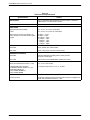
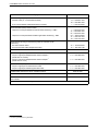
Table 1-2
DSU Technical Specifications
Criteria
Specifications
APPLICATION
Full- or half-duplex data transmission via point-to-point or multipoint
DDS network, or local area data channel
COMMUNICATION LINE
Leased or private 4-wire DDS line
DATA RATES
Digital Services (DDS, ASDS)
2.4, 4.8, 9.6, 19.2, 38.4, and 56 kbps
LADS
2.4, 4.8, 9.6, 19.2, 38.4, 56, and 64 kbps
When timing is external (provided by the
DTE), the DTE’s clock must be within these
ranges.
64 kbps " 11 bps
56 kbps " 9 bps
38.4 kbps " 4 bps
19.2 kbps " 5 bps
9.6 kbps " 1 bps
4.8 kbps " 0 bps
2.4 kbps " 0 bps
DDS NETWORK INTERFACE
3550 DSU
8-pin modular jack, USOC RJ48S
3551 DSU
(One or two) 50-pin connector, USOC RJ48T
DIAGNOSTIC INTERFACE
3550 DSU
Requires 3600 Series Hubbing Device which provides
two 8-pin modular jacks
3551 DSU
Via the SDU in the COMSPHEREr 3000 Series Carrier
NETWORK COMPATIBILITY
AT&T Technical Reference 62310 – 1987
2.4, 4.8, 9.6, and 56 kbps
Integrated Network Corporation
Compatibility Bulletin CB-INC-101, and
Pacific Bell publications
PUB L-780035-PB/NB and
PUB L-780036-PB/NB
19.2 kbps loop at levels of +6, 0, or –10 dBm
DSU COMPATIBILITY
Primary Channel
1-6
All Paradyne digital products and other products that are compliant with
AT&T Technical Reference 62310 – 1987
December 1996
3550-A2-GB20-20
About Your DSU
Table 1-3
V.32 DBM Technical Specifications
Criteria
Specifications
RINGER EQUIVALENCE NUMBER (REN)
DBM option 0.7B
APPLICATION
Full- or half-duplex data transmission via analog 2-wire dial network,
point-to-point
MODULATION AND FREQUENCY
At 14.4 and 12 kbps: CCITT V.32bis, 1800 Hz
At 4.8 and 9.6 kbps: CCITT V.32, 1800 Hz
At 2.4 kbps: CCITT V.22bis, 2400 Hz
COMMUNICATION LINE
2-wire analog (PSTN) line
DATA RATES
2.4, 4.8, 9.6, 12, 14.4 kbps
DBM COMPATIBILITY
If Call Setup is set for Callback or Password security, then the device is
compatible with a Model 3550 or 3551 V.32 DBM.
If Call Setup is set for Alarm or None, then any V.32 modem can be
used.
Also, V.22bis at 2.4 kbps can be used.
APPROVALS
DOC
Certification (PSTN)
Load Number
230 3684 A
7
RECEIVE VF INTERFACE
Dynamic Range
V.32 2-wire PSTN
Impedance
– 43 to –10 dBm
600 Ω
SWITCHED NETWORK INTERFACE
3550 DSU
6-pin modular jack
Permissive: USOC RJ11C
8-pin modular jack
Programmable: USOC RJ45S
3551 DSU
(One or two) 50-pin connector
Permissive: USOC RJ21X
Programmable: USOC RJ27X
TRANSMIT VF INTERFACE
Signal Level
V.32 2-wire Dial (PSTN)
Impedance
3550-A2-GB20-20
Permissive: – 9 dBm
Programmable: –12 to 0 dBm (set by a resistor in the telco jack)
600 Ω
December 1996
1-7
COMSPHERE 3550 Series Data Service Units
Table 1-4
2-Port TDM/Flex Technical Specifications
Criteria
Specifications
APPLICATION
Multiplexing
Provides time division multiplexing of two independent ports.
Digital sharing
Allows consecutive ports to share the same TDM/Flex channel.
PORT SYNCHRONOUS RATES
1.2, 2.4, 4.8, 9.6, 12.0, 14.4, 19.2, 48, 56, and 64 kbps
PORT ASYNCHRONOUS RATES
150, 300, 600, 1200, and 1800 bps plus all primary (DSU) rates.
Asynchronous rates support +2.3, –2.5 percent overspeed/
underspeed compensation.
PORT DTE INTERFACE
3550 DSU (2-port TDM/Flex)
Provides an additional 25-pin D-subminiature connector for a total of two
EIA-232 or V.35 interfaces.
NMS SUPPORT
TDM/Flex capability is fully supported by Release 4.0 or greater
COMSPHERE 6700 Series NMS.
Equipment Warranty
and Support
Contact your sales or service representative directly for
any help needed. For additional information concerning
warranty, sales, service, repair, installation,
documentation, or training, use one of the following
methods:
• Via the Internet: Visit the Paradyne World Wide
Web site at http://www.paradyne.com
• Via Telephone: Call our automated call system to
receive current information via fax or to speak with
a company representative.
— Within the U.S.A., call 1-800-870-2221
— International, call 727-530-2340
1-8
December 1996
3550-A2-GB20-20
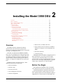
Installing the Model 3550 DSU
Overview . . . . . . . . . . . . . . . . . . . . . . . . . . . . . . . . . . . . . . . . . . . . . . . . . . . . . . . . . . . . . . . . . . . . . . . . . .
Before You Begin . . . . . . . . . . . . . . . . . . . . . . . . . . . . . . . . . . . . . . . . . . . . . . . . . . . . . . . . . . . . . . . . . . .
How to Change Hardware Straps . . . . . . . . . . . . . . . . . . . . . . . . . . . . . . . . . . . . . . . . . . . . . . . . . . . . . . .
Where to Place the DSU . . . . . . . . . . . . . . . . . . . . . . . . . . . . . . . . . . . . . . . . . . . . . . . . . . . . . . . . . . . . . .
Installing the DSU . . . . . . . . . . . . . . . . . . . . . . . . . . . . . . . . . . . . . . . . . . . . . . . . . . . . . . . . . . . . . . . . . . .
Power-Up Routine . . . . . . . . . . . . . . . . . . . . . . . . . . . . . . . . . . . . . . . . . . . . . . . . . . . . . . . . . . . . . . . .
Connecting to the Network . . . . . . . . . . . . . . . . . . . . . . . . . . . . . . . . . . . . . . . . . . . . . . . . . . . . . . . . . . . .
Connecting to the NMS . . . . . . . . . . . . . . . . . . . . . . . . . . . . . . . . . . . . . . . . . . . . . . . . . . . . . . . . . . . .
Connecting to the Dial (or PSTN) Network . . . . . . . . . . . . . . . . . . . . . . . . . . . . . . . . . . . . . . . . . . . .
Connecting to the DDS (or LADS) Network . . . . . . . . . . . . . . . . . . . . . . . . . . . . . . . . . . . . . . . . . . .
Addressing the Unit . . . . . . . . . . . . . . . . . . . . . . . . . . . . . . . . . . . . . . . . . . . . . . . . . . . . . . . . . . . . . . . . .
Tributary DSU Addressing . . . . . . . . . . . . . . . . . . . . . . . . . . . . . . . . . . . . . . . . . . . . . . . . . . . . . . . . .
Connecting the DSU to a DTE . . . . . . . . . . . . . . . . . . . . . . . . . . . . . . . . . . . . . . . . . . . . . . . . . . . . . . . . .
Connecting Port 2 . . . . . . . . . . . . . . . . . . . . . . . . . . . . . . . . . . . . . . . . . . . . . . . . . . . . . . . . . . . . . . . .
Verifying Operation and Testing Connections . . . . . . . . . . . . . . . . . . . . . . . . . . . . . . . . . . . . . . . . . . . . .
Verifying Network Addresses . . . . . . . . . . . . . . . . . . . . . . . . . . . . . . . . . . . . . . . . . . . . . . . . . . . . . . .
Verifying the Network . . . . . . . . . . . . . . . . . . . . . . . . . . . . . . . . . . . . . . . . . . . . . . . . . . . . . . . . . . . . .
Verifying DBM Operation . . . . . . . . . . . . . . . . . . . . . . . . . . . . . . . . . . . . . . . . . . . . . . . . . . . . . . . . . .
Verifying TDM/Flex Operation . . . . . . . . . . . . . . . . . . . . . . . . . . . . . . . . . . . . . . . . . . . . . . . . . . . . . .
Other Tests . . . . . . . . . . . . . . . . . . . . . . . . . . . . . . . . . . . . . . . . . . . . . . . . . . . . . . . . . . . . . . . . . . . . . .
2
2-1
2-1
2-2
2-4
2-4
2-5
2-5
2-6
2-6
2-7
2-8
2-9
2-10
2-11
2-11
2-11
2-11
2-12
2-12
2-12
• DDS network (or LADS) connection
Overview
The Model 3550 DSU is designed for desktop
operation and is delivered ready to connect to the
network. It is configured as a tributary DSU for operation
at 9.6 kbps on a multipoint circuit.
If the unit was ordered with a TDM/Flex installed,
Ports 1 and 2 are configured for 9.6 kbps operation, and
configured as a digital sharing device (DSD). Both ports
are configured for EIA-232 operation, rather than V.35
operation. Refer to the MUX (Port) option set tables in
Chapter 5 to change this configuration on a port-by-port
basis.
• Dial (or PSTN) network connection if a DBM is
installed, or if using an external dial backup unit
(DBU)
• DSU DTE connection
• Verification testing
Although the Model 3550 DSU is designed for desk or
table-top operation, you can order an ACCULINKr
3100 Series CSU wall-mount adapter if you want to
mount the DSU on a wall, an equipment shelf, a 19-inch
RS-310-C or 23-inch AT&T DATAPHONEr equipment
cabinet. Refer to Appendix F to order the adapter.
Installation consists of the following steps, which
should be performed in the order listed.
• Physical installation
Before You Begin
• Hardware straps
Your installation site should be clean, well-lighted,
well-ventilated, and free from environmental extremes.
• Electrical connection
• Network diagnostic connection
• Software configuration
3550-A2-GB20-20
A dedicated grounded ac outlet that is protected by a
circuit breaker should be installed within 6 feet of the
DSU’s planned location. The outlet should be capable of
supplying 90 to 132 Vac 60 Hz (U.S. and Canada). The
December 1996
2-1
COMSPHERE 3550 Series Data Service Units
circuit must be capable of supplying a minimum of
2 amperes at 115 Vac. Refer to the Technical
Specifications section in Chapter 1 for additional power
requirements.
CAUTION
The ac transformer contains a
3-wire grounding-type plug which
has a grounding pin. This is a
safety feature. Do not defeat the
purpose of the grounding plug by
modifying it or by using an
adapter.
Contact your service representative if any of these
items is missing from the shipping container, or to order
the appropriate dial interface cable.
If your DSU is equipped with a DBM, you may need to
change the DSU’s hardware straps before installing the
DSU.
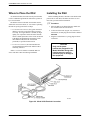
How to Change
Hardware Straps
HANDLING PRECAUTIONS
FOR
STATIC-SENSITIVE DEVICES
Prior to installation, use an outlet
tester to check the ac receptacle
for earth ground. If the power
source does not provide a ground
connection, consult an electrician
to determine another method of
grounding the DSU before
proceeding with the installation.
Before connecting the DSU, you need to contact the
telephone company to coordinate your installation before
connecting the DSU to their network. The DSU can only
be operated at the data rate for which access to the DDS
network is provided. If a DBM is installed, the DSU must
also be connected to the dial network. You must notify the
telephone company before you connect to the dial
network. Refer to the notice at the front of this guide to
ensure compliance with FCC, Bell Canada, and Canadian
DOC rules.
No on-site assembly of the DSU is required. However,
installation should not proceed if any of the following is
missing:
• A power cord with table-top ac transformer
This product is designed to protect
sensitive components from damage
due to electrostatic discharge (ESD)
during normal operation. When
performing installation procedures,
however, take proper static control
precautions to prevent damage to
equipment. If you are not sure of the
proper static control precautions,
contact your nearest sales or service
representative.
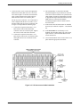
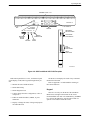
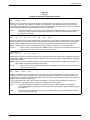
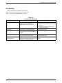
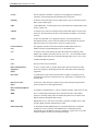
The Model 3550 DSU has a switch located behind its
diagnostic control panel (DCP). This switch contains two
straps, one that controls the permissive or programmable
connection when a DBM is installed, and one that controls
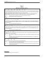
the frame-to-signal grounds. Table 2-1 shows the DSU’s
settings. Refer to Figure 2-1 and the following steps if you
need to change one of these straps.
.
• A 14-ft cable for connection to the DDS network,
with 8-pin RJ48S modular plug on each end
For Canadian purchasers, an 8-pin RJ48S connector is
on one end while a 6-pin connector is on the other is
required (order feature number 3000-F1-006).
If the DSU is equipped with a DBM, a dial interface
cable should have been ordered.
• Permissive (RJ11C) – a 6-pin modular plug at each
end (feature number 4400-F1-53x or 3600-F3-503).
Procedure
1. With your thumbs under the edge of the front
bezel, firmly press upward to lift the bezel from
the tabs securing it in place.
2. Swing the front bezel up and set the bezel aside.
3. Refer to Table 2-1 to determine which switch
needs to be changed. Then, using a small
instrument, carefully change the position of the
switch.
4. Reinsert the front bezel’s hinge tabs into position
and swing the bezel down. Snap the bezel back
into place.
• Programmable (RJ45S) – an 8-pin modular plug at
each end (feature number 4400-F1-54x).
2-2
December 1996
3550-A2-GB20-20
Installing the Model 3550 DSU
FRONT BEZEL
C
O
H
SP
M
ER
E
50
35
SNAP
TABS
SWITCH 1
HINGE TAB
LOCATIONS
496-14457-01
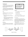
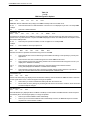
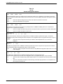
Figure 2-1. Model 3550 Hardware Switch Location (shown without a TDM/Flex)
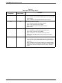
Table 2-1
Model 3550 DSU Switch Settings
Switch Position
S1-1
S1-2
Switch Setting
ON
(default)
Function
Permissive V.32 DBM transmit output level of –9 dBm
Off
Programmable V.32 DBM transmit level between –12 dBm and 0 dBm
ON
Frame ground (FG) connected to signal ground (SG)
Off
(default)
FG connected to SG through 100 ohm resistor
ON is to the rear as you face the front of the DSU.
Off is to the front.
3550-A2-GB20-20
December 1996
2-3
COMSPHERE 3550 Series Data Service Units
Where to Place the DSU
Installing the DSU
As mentioned earlier, the DSU must be placed within
6 feet of a dedicated grounded ac outlet that is protected
by a circuit breaker.
Before installing the DSU, label the circuit breaker that
protects the ac wall outlet, and make sure that it is set to
ON. Then, proceed with the installation.
The distance between the DSU and its DTE must be
within EIA-232-D/V.24 limits, or V.35 limits if operating
the DSU at speeds greater than 19.2 kbps.
.
• For the EIA-232 connector, the typical maximum
distance is 50 feet at speeds less than or equal to
19.2 kbps. If a longer distance is needed, use high
quality, low capacitance cable and ensure that the
effective shunt capacitance of the circuit (measured
at the DSU and including the capacitance of the
cable and the DTE) does not exceed 2500
picofarads, as specified in EIA-232-D.
• For the V.35 connector, the maximum distance
recommended between the DSU and the DTE is
nominally 1000 feet.
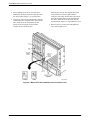
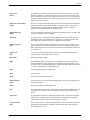
Procedure
1. Place the DSU in its planned location. Make sure
the ventilation slots are not blocked.
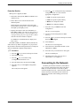
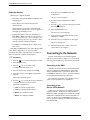
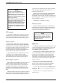
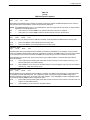
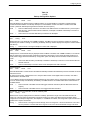
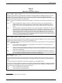
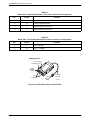
2. At the rear of the DSU (Figure 2-2), insert the ac
transformer, circular plug into the interface labeled
POWER.
3. Plug the ac transformer’s 3-prong plug into the ac
wall outlet.
CAUTION
Only use the power
transformer designed for the
Model 3550 DSU. Using other
transformers may result in
personal injury or damage to
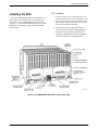
the equipment.
Allow 1 to 2 feet of clearance around the DSU for
access and cable connections during installation.
Figure 2-2. Model 3550 Electrical Connection
2-4
December 1996
3550-A2-GB20-20
Installing the Model 3550 DSU
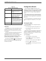
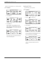
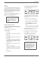
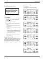
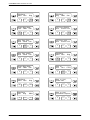
Power-Up Routine
6. Press the
key to bring the factory-loaded unit
configurations into view, and select the
appropriate configuration.
When power is applied, the DSU:
• Determines what options (DBM or TDM/Flex) are
installed, if any.
• PTPC for a point-to-point control
• Runs a Device Test on itself and each of the
installed options.
• MPTC for a multipoint control
• PTPT for a point-to-point tributary
• MPTT for a multipoint tributary
During the tests, all indicators on the DCP light
briefly and the message Power-Up Tests appears on
the liquid crystal display (LCD).
7. Press the F1 key to SAVE the selected
configuration.
• Displays the results of each test momentarily as
Pass, Fail, or Abrt. (Abrt indicates that the Device
Test was aborted because a network loopback was
in progress during the power-up procedure.) These
tests take about 20 seconds to complete.
If a TDM/Flex is installed, MUX is displayed as
Pass or Fail.
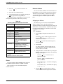
Procedure
1. Press the
key to return to the top-level menu,
9. Press the
then select Local again.
The Run Test on screen appears.
11. Select the device that Failed: the DSU (or the
TDM/Flex) or DBM.
12. Press the F2 key to run the Device Test again.
key to return to the top-level menu.
2. Select Local (F1 key).
key to scroll the Confg
3. Press the
(Configuration) branch into view.
4. Press the function key directly below Confg.
5. Press the F1 key to select Opts (Configuration
Options).
The Load from screen appears.
3550-A2-GB20-20
8. Save the selected configuration to Activ
(F1 key).
10. Select Test (F3).
If the DSU, DBM, or TDM/Flex (MUX) fails this test,
follow these steps. Refer to Appendix A as you perform
the procedures described in this guide. Refer to Chapters 4
and 5 for additional examples and procedures.
.
The Save to screen appears.
The device should pass.
13. Should the device fail, call your service
representative. (see Chapter 1).
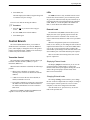
Connecting to the Network
The DSU provides three interfaces (often called a
jack). One jack connects the DSU to the 6700 Series
NMS, one connects the DSU to the dial (or public
switched telephone network – PSTN) network, and one
connects the DSU to the DDS network. Follow the
appropriate procedure when making your network
connections.
December 1996
2-5
COMSPHERE 3550 Series Data Service Units
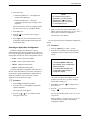
Connecting to the NMS
Connecting to the Dial (or PSTN) Network
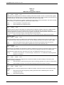
A 3600 Hubbing Device is required to connect the
control DSU to the 6700 Series NMS. When connected to
the NMS, the DSU can be controlled and configured from
the NMS rather than from the DCP alone.
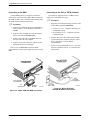
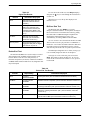
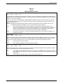
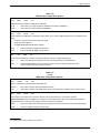
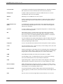
If your DSU is equipped with a V.32 DBM, refer to
Figure 2-4 as you follow these steps.
.
.
Procedure
1. Plug either end of the dial (analog) interface cable
into the DSU jack labeled BACKUP.
Procedure
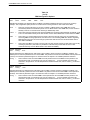
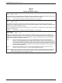
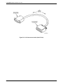
1. Plug the 4-pin modular plug of the 3600 Hubbing
Device (Figure 2-3) into the DSU jack labeled
CC/DC.
• Permissive service – telephone cord with 6-pin
modular RJ11C plug
2. Plug one end of an M6BJ cable into the hubbing
device jack labeled CC IN/DC OUT.
• Programmable service – telephone cord with
8-pin RJ45S plug
3. Plug the other end of the 8-pin M6BJ cable into
the 8-pin end of the 873A adapter.
4. Plug the D-type end of the 873A adapter into the
appropriate 6700 Series NMS jack.
Refer to your COMSPHERE 6700 Series NMS
documentation to control and configure the DSU from the
NMS.
2. Plug the other end of the cable into the modular
jack provided by the telephone company, USOC
RJ11C (permissive) or USOC RJ45S
(programmable).
3. If your site has programmable service, verify that
the DSU’s hardware strap S1-1 is switched to the
OFF position.
NMS NETWORK
CONNECTION
CC/DC
LOW VOLTAGE
AC POWER IN
TO
NMS (873A)
VICE
DE -300
ING 0-F3
BB
HU #300
00
30 ODEL
M
HUBBING
DEVICE
496-14576a
Figure 2-3. Model 3550 DSU NMS Connection
2-6
December 1996
Figure 2-4. Model 3550 DSU
Dial (PSTN) Network Connection
3550-A2-GB20-20
Installing the Model 3550 DSU
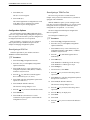
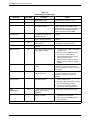
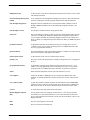
Connecting to the DDS (or LADS) Network
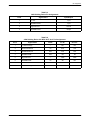
If connecting the DSU to a LADS network, there are
distance limitations that govern the use of DSUs on the
network. Table 2-2 summarizes these limitations.
NOTE
Before connecting the DSU to the
DDS network, ensure that approved
primary protectors have been
installed on the circuit in accordance
with Article 800 of the National
Electric Code, NFPA 70, in the United
States and Section 60 of the
Canadian Electric Code, Part 1, in
Canada.
Refer to Figure 2-5 as you follow these steps.
.
Procedure
1. Plug the DDS network interface cable into the
DSU jack labeled LINE.
• U.S. – select either end of the cable
• Canada – select the 8-pin end
2. Plug the other end of the cable into the modular
jack (USOC RJ48S) provided by the circuit
provider.
Figure 2-5. Model 3550 DSU DDS (LADS)
Network Connection
If the remote DSU is also connected to the network, the
DSU’s green OK indicator lights and the Alrm indicator
goes off. The Health and Status screen no longer displays
a No Signal message.
3550-A2-GB20-20
December 1996
2-7
COMSPHERE 3550 Series Data Service Units
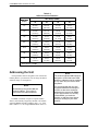
Table 2-2
LADS Connection Distances
Wire Gauge (AWG)
Data Rate
(kbps)
19
22
24
26
2.4
20.0 mi
16.6 mi
12.7 mi
9.4 mi
(32.2 km)
(26.7 km)
(20.5 km)
(15.1 km)
4.8
9.6
19.2 1
38.4
56
64
1
19.4 mi
12.7 mi
9.6 mi
7.1 mi
(31.2 km)
(20.5 km)
(15.4 km)
(11.5 km)
15.2 mi
9.7 mi
7.3 mi
5.6 mi
(24.5 km)
(15.6 km)
(11.7 km)
(9.0 km)
11.8 mi
7.5 mi
5.7 mi
4.2 mi
(19.0 km)
(12.1 km)
(9.2 km)
(6.8 km)
11.2 mi
6.5 mi
4.6 mi
3.2 mi
(18.0 km)
(10.5 km)
(7.4 km)
(5.1 km)
9.2 mi
5.4 mi
3.8 mi
2.8 mi
(14.8 km)
(8.7 km)
6.2 km)
(4.5 km)
9.2 mi
5.4 mi
3.8 mi
2.8 mi
(14.8 km)
(8.7 km)
(6.2 km)
4.5 km)
Power level is –10 dBm.
Addressing the Unit
NOTE
A unique address must be assigned to each control and
tributary DSU in your network. You can assign an address
within the range of 1 through 255.
NOTE
Do not assign the number 192 as a
network address. This number is
reserved as a broadcast address.
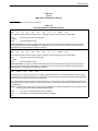
If a DBM is installed, it requires a separate address
which is automatically assigned by the DSU. The address
assigned a DBM is the DSU’s address, plus 1 (e.g., if the
DSU’s address is 1, the assigned DBM address will be 2).
2-8
December 1996
The numbers 191 and 255 cannot be
assigned to a DSU that has a DBM.
However, addresses can be assigned
in any order; they do not have to be
sequential.
It is recommended that only oddnumbered addresses be assigned
to DSUs so that even-numbered
addresses are reserved for DBMs.
If your network does not currently
include DBMs, you retain the
flexibility to add them later without
having to reconfigure your entire
network.
3550-A2-GB20-20
Installing the Model 3550 DSU
Tributary DSU Addressing
Tributary DSU addresses are user-definable, but take
care that their addresses are unique on a multipoint circuit.
If two tributaries are assigned the same address, you will
not be able to communicate with either one.
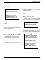
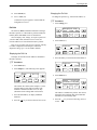
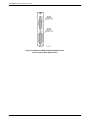
The control DSU accesses its tributary by specifying
the tributary’s address.
first addresses the control, then the tributary. An address
issued from the NMS takes the format of control
channel/control network address/tributary network
address. This is called link-level network addressing.
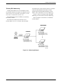
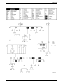
Figure 2-6 shows an example of DSU and DBM
addressing, as well as link-level network addressing.
Refer to Chapter 4 to learn how to set the DSU’s
network address.
The 6700 Series NMS accesses the DSU via its
network address. To access a tributary DSU, the NMS
Figure 2-6. Addressing Example
3550-A2-GB20-20
December 1996
2-9
COMSPHERE 3550 Series Data Service Units
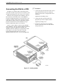
Connecting the DSU to a DTE
.
The DSU’s rear panel has both a 25-pin EIA-232-D/
V.24 connector and a 34-pin CCITT V.35 connector (used
for higher operating speeds). You can use either interface.
When the unit is equipped with a TDM/Flex, either of
these interfaces can be used as Port 1. The TDM/Flex
provides an additional interface to be used as Port 2. This
is a D-type connector. If the port is to operate at a speed
greater than 19.2 kbps, use the V.35 interconnect cable to
provide an interface between the TDM/Flex’s D-type
connector and the DTE cable’s V.35 connector.
Figure 2-7 shows a DSU as well as a DSU equipped
with a TDM/Flex. The DSU without TDM/Flex illustrates
cabling for an EIA-232 application; the DSU with
TDM/Flex illustrates cabling for V.35 applications. Refer
to this figure as you connect your DSU to the data
terminal equipment (DTE). Be sure to select the
appropriate cable, EIA-232 or V.35, for your application.
Procedure
1. Connect the plug end of the DTE cable to Port 1,
either the EIA-232-D or the V.35 connector.
(Figure 2-7 shows Port 1 using the EIA-232-D
connector.)
Tighten the two holding screws.
2. Connect the other end of the cable to the
appropriate port on the computer or DTE.
Tighten any holding screws.
3. If necessary, activate the port to match the
interface, either EIA-232 or V.35 (the default
setting is EIA-232).
Figure 2-7. Installing Cables
2-10
December 1996
3550-A2-GB20-20
Installing the Model 3550 DSU
Connecting Port 2
3. Select Stat (Status branch).
4. Press the
For the EIA-232 cable, install as described above.
5. Select ID.
For the V.35 cable, install the V.35 Interconnect Cable,
then the V.35 DTE cable as follows (refer to Figure 2-7).
.
key until ID appears.
6. Press the
Procedure
key until Network Addr appears.
7. Verify that the correct address has been entered.
1. Reconfigure the port to match the interface, V.35
in this example.
Repeat this procedure for each tributary DSU in the
network.
2. Connect the 25-pin plug end of the V.35
Interconnect Cable (feature number 3000-F1-510)
to Port 2.
Verifying the Network
Perform a Digital Test on the DDS circuit to ensure
that the network is functioning.
Tighten the holding screws.
.
3. Connect the plug end of the 34-pin V.35 DTE
cable to the other end of the V.35 Interconnect
Cable.
Procedure
1. Select Test (F3).
Tighten the holding screws.
2. Select DSU (F1).
4. Connect the other end of the DTE cable to the
appropriate port on the computer or DTE.
3. Press the
key until DT appears.
4. Select DT.
Tighten the holding screws.
5. Select Start (F1).
Refer to Chapter 4 to learn how to reconfigure the
DSU’s port(s).
6. Select a port.
7. Enter the address of the remote DSU.
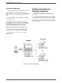
Verifying Operation and
Testing Connections
8. Select the amount of time you want the test to run
in hours: minutes: seconds (hh:mm:ss).
• Press the
or
key to move the blinking
cursor to the digit to be changed.
Verification testing should be performed after any
installation.
• Press the F1 (") key to increment the digit
(1 through 9).
After installing and configuring the circuit (including
control and tributary DSUs, the DDS network, the DBMs
and their dial connections), perform the following series
of tests from the control DSU to verify network operation
(using either the DCP or NMS).
Verifying Network Addresses
Access the DSU’s identity (ID) subbranch for each
tributary DSU to ensure that the DSUs are properly
addressed. Refer to Chapter 5 for an example using the
DCP, if needed.
.
Procedure
• Press the F2 (↓) key to decrement the digit.
9. Select Enter (F3). Please wait appears as the DSU
starts the test.
10. When Command Complete appears, press the
key.
11. Select Displ (F1) to display the results of the test.
Table 4-6 in Chapter 4 shows the information
received from a Digital Test.
12. Press the
key to scroll through each result.
1. Select Remot (Remote branch).
2. Enter the tributary’s network address.
3550-A2-GB20-20
December 1996
2-11
COMSPHERE 3550 Series Data Service Units
Verifying DBM Operation
Other Tests
If a DBM is installed, test the tributary DBM for
dial tone, and verify that the DSU can place and receive
calls.
The following lists the tests available on your DSU.
Refer to the Test Branch section of Chapter 4 for further
test information, as well as more detail on how to
configure and operate the DSU. Refer to Appendix A to
determine how best to access each test.
.
Procedure
1. Select Bckup (F2).
• Device Test (Devic)
2. Select Dial to establish a dialed call to the
tributary.
• Local Loopback (LL)
(Refer to Chapter 4 for the procedure for entering
telephone numbers.)
• DTE Loopback (DTE)
• Digital Loopback (DL)
3. Select !Dial to switch to the dial circuit.
• Remote Digital Loopback (RL)
4. Perform a Digital Test following the DBM path
rather than the DSU path.
• Bilateral Loopback
(No error message should appear.)
• Digital Test (DT)
• End-to-End Test (EE)
5. Select DrBU to drop the backup call.
• Bit Error Rate Test (BERT)
6. Perform a Digital Test on the DBM. Follow the
Verifying the Network procedure, selecting DBM
instead of DSU (Step 2).
• Lamp Test (Lamp)
Verifying TDM/Flex Operation
If a TDM/Flex is installed, perform a Digital Test on
each port.
2-12
December 1996
3550-A2-GB20-20
Installing the Model 3551 DSU
Overview . . . . . . . . . . . . . . . . . . . . . . . . . . . . . . . . . . . . . . . . . . . . . . . . . . . . . . . . . . . . . . . . . . . . . . . . . .
Before You Begin . . . . . . . . . . . . . . . . . . . . . . . . . . . . . . . . . . . . . . . . . . . . . . . . . . . . . . . . . . . . . . . . . . .
How to Change Hardware Straps . . . . . . . . . . . . . . . . . . . . . . . . . . . . . . . . . . . . . . . . . . . . . . . . . . . . . . .
Installing the DSU . . . . . . . . . . . . . . . . . . . . . . . . . . . . . . . . . . . . . . . . . . . . . . . . . . . . . . . . . . . . . . . . . . .
Power-Up Routine . . . . . . . . . . . . . . . . . . . . . . . . . . . . . . . . . . . . . . . . . . . . . . . . . . . . . . . . . . . . . . . .
Connecting to the Network . . . . . . . . . . . . . . . . . . . . . . . . . . . . . . . . . . . . . . . . . . . . . . . . . . . . . . . . . . . .
Connecting to the NMS . . . . . . . . . . . . . . . . . . . . . . . . . . . . . . . . . . . . . . . . . . . . . . . . . . . . . . . . . . . .
Connecting to the Dial (or PSTN) Network . . . . . . . . . . . . . . . . . . . . . . . . . . . . . . . . . . . . . . . . . . . .
Connecting to the DDS (or LADS) Network . . . . . . . . . . . . . . . . . . . . . . . . . . . . . . . . . . . . . . . . . . .
Connecting the DSU to a DTE . . . . . . . . . . . . . . . . . . . . . . . . . . . . . . . . . . . . . . . . . . . . . . . . . . . . . . . . .
Addressing the Unit . . . . . . . . . . . . . . . . . . . . . . . . . . . . . . . . . . . . . . . . . . . . . . . . . . . . . . . . . . . . . . . . .
Tributary DSU Addressing . . . . . . . . . . . . . . . . . . . . . . . . . . . . . . . . . . . . . . . . . . . . . . . . . . . . . . . . .
Verifying Operation and Testing Connections . . . . . . . . . . . . . . . . . . . . . . . . . . . . . . . . . . . . . . . . . . . . .
To Connect the SDCP to a DSU . . . . . . . . . . . . . . . . . . . . . . . . . . . . . . . . . . . . . . . . . . . . . . . . . . . . .
Verifying Network Addresses, the Network, and DBM Operation . . . . . . . . . . . . . . . . . . . . . . . . . . .
Other Tests . . . . . . . . . . . . . . . . . . . . . . . . . . . . . . . . . . . . . . . . . . . . . . . . . . . . . . . . . . . . . . . . . . . . . .
Overview
A Model 3551 DSU is designed for installation in a
COMSPHERE 3000 Series Carrier, which supplies power
and provides the interfaces for connecting to the DDS or
dial networks. Up to 16 DSUs can be installed in the
carrier. Refer to the COMSPHERE 3000 Series Carrier,
Installation Manual for additional carrier and installation
information.
The DSU is delivered ready to install in the carrier. It is
configured as a control DSU for operation at 9.6 kbps on a
multipoint circuit.
A rear connector plate, which is installed onto the rear
of the carrier, is shipped with the DSU. The rear connector
plate contains two connectors: a 25-pin EIA-232-D/V.24
connector and a 25-pin V.35 connector. Once installed, the
DSU can be removed from the front of the carrier without
disconnecting the DTE cables.
3550-A2-GB20-20
3
3-1
3-2
3-2
3-5
3-8
3-8
3-8
3-8
3-9
3-9
3-9
3-10
3-10
3-11
3-11
3-12
Installation of the DSUs and carrier-related equipment
consists of the following steps, which should be
performed in the order listed.
• Hardware straps
• DSU physical installation
• Network diagnostic connection
• Software configuration
• DDS network (or LADs) connection
• Dial (or PSTN) network connection
(if a DBM is installed)
• DSU DTE connection
• Verification testing
December 1996
3-1
COMSPHERE 3550 Series Data Service Units
Before You Begin
The COMSPHERE 3000 Series Carrier should already
be installed properly and be operational, with a
functioning shared diagnostic control panel (SDCP). An
SDCP (installed in the carrier) is required for installation
and maintenance of the Model 3551 DSU. For installation
information, see the COMSPHERE 3000 Series Carrier,
Installation Manual.
How to Change
Hardware Straps
HANDLING PRECAUTIONS
FOR
STATIC-SENSITIVE DEVICES
This product is designed to protect
sensitive components from damage
due to electrostatic discharge (ESD)
during normal operation. When
performing installation procedures,
however, take proper static control
precautions to prevent damage to
equipment. If you are not sure of the
proper static control precautions,
contact your nearest sales or service
representative.
A fan module may also be needed to dissipate heat.
Refer to the Fan Module Installation section in Chapter 3
of the COMSPHERE 3000 Series Carrier, Installation
Manual to determine whether a fan is required.
The distance between your DTE and the DSU must be
within EIA-232-D/V.24 or V.35 limits.
• For the EIA-232 connector, the typical maximum
distance is 50 feet at speeds less than or equal to
19.2 kbps. If a longer distance is needed, use high
quality, low capacitance cable and ensure that the
effective shunt capacitance of the circuit (measured
at the DSU and including the capacitance of the
cable and the DTE) does not exceed 2500
picofarads, as specified in EIA-232-D.
• For the V.35 connector, the recommended
maximum distance between a DTE and DSU is
nominally 1000 feet.
Before connecting the DSU, you need to contact the
telephone company to coordinate your installation before
connecting the DSU to their network. The DSU can only
be operated at the data rate for which access to the DDS
network is provided. If a DBM is installed, the DSU must
also be connected to the dial network. You must notify the
telephone company before you connect to the dial
network. Refer to the notice at the front of this guide to
ensure compliance with FCC, Bell Canada, and Canadian
DOC rules.
3-2
The Model 3551 DSU has several hardware straps that
control the permissive or programmable connection when
a DBM is installed, the Test Mode Indication leads, and
the external interface leads (used with a –48 Vdc Central
Office Power Unit).
Refer to Figure 3-1 to locate the switch and jumper
locations. If a DBM is installed, refer to Table 3-1 to
determine which switch needs to be changed, if any. Refer
to Table 3-2 to determine whether these jumper straps
need to be changed.
December 1996
3550-A2-GB20-20
Installing the Model 3551 DSU
Figure 3-1. Model 3551 DSU Switch and Jumper Locations
Table 3-1
Model 3551 DSU Switch Settings
Switch Position
Switch Setting
ON
(default)
Function
Permissive V.32 DBM transmit output level of –9 dBm
S1-1
S1-2
Off
Programmable V.32 DBM transmit level between –12 dBm and
0 dBm
ON
Frame ground (FG) connected to signal ground (SG)
Off
(default)
FG connected to SG through 100 ohm resistor
ON is to the rear as you face the front of the DSU.
Off is to the front.
3550-A2-GB20-20
December 1996
3-3
COMSPHERE 3550 Series Data Service Units
Table 3-2
Model 3551 DSU Jumper Straps
Strap
Designation
State of
Jumper Strap
J12
Left
Function
V.35 Test Mode Indication:
Left — Enables V.35 Test Mode Indication (Pins 1 and 2). This is the
factory default.
Right — Disables V.35 Test Mode Indication (Pins 2 and 3).
J13
Left
EIA-232-D Test Mode Indication:
Left — Enables EIA-232-D Test Mode Indication
(Pins 1 and 2). This is the factory default.
Right — Disables EIA-232-D Test Mode Indication
(Pins 2 and 3).
J20
Left
Alarm Monitoring (used with the –48 Vdc Central Office Power Unit):
Left — Disables the – 48 Vdc alarm monitoring function
(Pins 1 and 2). This is the factory default.
Right — Enables the – 48 Vdc alarm monitoring function
(Pins 2 and 3); the NMS adapter cable is being used for alarm
monitoring.
J21
Right
Alarm Monitoring (used with the –48 Vdc Central Office Power Unit):
Left — Enables control of alarm monitoring via the NMS adapter
cable (Pins 1 and 2); the NMS adapter cable is being used for alarm
monitoring.
Right — Disables control of alarm monitoring via the NMS adapter
cable (Pins 2 and 3); a standard EIA-232 cable or the NMS adapter
cable is being used for the diagnostic channel. This is the factory
default.
3-4
December 1996
3550-A2-GB20-20
Installing the Model 3551 DSU
.
Installing the DSU
The initial installation procedure for the Model 3551
DSU requires the installation of a rear connector plate
onto the rear of the COMSPHERE 3000 Series Carrier
(Figure 3-2). After the initial installation, the DSU can be
installed or de-installed by simply removing the DSU
from the carrier.
Procedure
1. At the rear of the carrier, set the tab on the rear
connector plate into one of the slotted grooves on
the carrier’s backplane. Loosely fasten the screws.
Make sure the rear connector plate uses the same
slot position intended for the DSU.
2. Loosely fasten the screw attached to the rear
connector plate, allowing for slight adjustment
that may be needed when installing the DSU.
3. Change any default hardware strap settings that
may be required before installing the DSU.
Figure 3-2. COMSPHERE 3000 Series Carrier, Rear View
3550-A2-GB20-20
December 1996
3-5
COMSPHERE 3550 Series Data Service Units
4. Using a Phillips screwdriver, loosen the screw
holding the circuit pack lock and rotate the lock to
the open position (Figure 3-3). Open the latch.
5. At the front of the carrier, hold the DSU vertically
with the latch on its faceplate in the open position.
Then, insert the circuit card into the top and
bottom circuit card guides for the slot that
contains the rear connector plate.
Slide the DSU into the slot, aligning the circuit
card with the rear connector plate until the
connectors seat firmly into the back of the carrier.
Press the faceplate latch to secure the DSU into
the carrier, rotate the circuit pack lock into the
closed position (Figure 3-3), and tighten the screw.
6. Return to the rear of the carrier and tighten the
rear connector plate screw.
Figure 3-3. Model 3551 DSU Installation and Circuit Pack Lock
3-6
December 1996
3550-A2-GB20-20
Installing the Model 3551 DSU
8. The installed DSU is connected to the DDS
network through the 50-pin connectors at the rear
of the carrier. These interfaces are specified in the
USOC RJ48T, and the pin assignments are shown
in Appendix D. Proper network connection to the
DDS facility or to the network channelterminating equipment must be made at the far
end of the cable.
7. At the rear of the carrier, connect the appropriate
DTE interface cable (EIA-232-D or V.35) to the
rear connector plate. For an EIA-232-D interface
cable, connect the EIA-232-D cable to the top
DTE connector on the rear connector plate.
For the 25-pin V.35 interface, a V.35 interconnect
cable is shipped with the unit. To connect a V.35
interface cable to the 25-pin V.35 connector, refer
to Figure 3-4 and perform the following steps:
a. Connect the 25-pin end of the DSU’s V.35
Interconnect Cable to the bottom DTE
connector of the rear connector plate. Tighten
the screws on each side of the connector.
b. Connect the 34-pin end of the DSU’s V.35
Interconnect Cable to the V.35 interface cable,
then tighten the screws on each side of this
connector.
9. If the network line and remote DSU are installed
and tested, do a Remote Loopback – a Test Pattern
test.
10. If the Front Panel test switch strap is to be
disabled, slide the DSU slightly out of the carrier,
open switch S3-1, then reseat the DSU into the
carrier. Do this now.
11. Circuit ID information can be written on the cover
plate under the appropriate slot number.
Figure 3-4. V.35 Interconnect Cable Installation
3550-A2-GB20-20
December 1996
3-7
COMSPHERE 3550 Series Data Service Units
Power-Up Routine
7. Press the F1 key to SAVE the selected
configuration.
When power is applied, the DSU:
The Save to screen appears.
• Determines what options (DBM or TDM/Flex) are
installed, if any.
8. Save the selected configuration to Activ
(F1 key).
• Runs a Device Test on itself and each of the
installed options.
key to return to the top-level menu,
9. Press the
then select Local again.
During the tests, all indicators on the DCP light
briefly and the message Power-Up Tests appears on
the liquid crystal display (LCD).
• Displays the results of each test momentarily as
Pass, Fail, or Abrt. (Abrt indicates that the Device
Test was aborted because a network loopback was
in progress during the power-up procedure.) These
tests take about 20 seconds to complete.
If a TDM/Flex is installed, MUX is displayed as
Pass or Fail.
Procedure
1. Press the
The Run Test on screen appears.
11. Select the device that Failed: the DSU (or the
TDM/Flex) or DBM.
12. Press the F2 key to run the Device Test again.
The device should pass.
13. Should the device fail, contact your service
representative (see Chapter 1).
If the DSU or DBM fails this test, follow the procedure
below. Refer to Appendix A as you perform the
procedures described in this guide. Refer to Chapters 4
and 5 for additional examples and procedures.
.
10. Select the Test branch (F3).
key to return to the top-level menu.
Connecting to the Network
Network connections are provided through the
3000 Series Carrier. Refer to Figure 3-2 as you read the
following sections and set up your network connections.
2. Select Local (F1 key).
Connecting to the NMS
key to scroll the Confg
3. Press the
(Configuration) branch into view.
A Model 3551 DSU is set up for network diagnostic
connection through the shared diagnostic unit (SDU),
which is installed in Slot 0 of the carrier. Refer to the
COMSPHERE 3000 Series Carrier, Installation Manual
to set up the network diagnostic connection.
4. Press the function key directly below Confg.
5. Press the F1 key to select Opts (Configuration
Options).
The Load from screen appears.
6. Press the
key to bring the factory-loaded unit
configurations into view, and select the
appropriate configuration.
• PTPC for a point-to-point control
• PTPT for a point-to-point tributary
• MPTC for a multipoint control
• MPTT for a multipoint tributary
3-8
For connection of the DSU, see Appendix E of this
guide. For pin assignments, see Appendix D.
Connecting to the
Dial (or PSTN) Network
Connection to the dial network (or public switched
telephone network – PSTN) for the carrier-mounted
Model 3551 DSU is through a network interface module
(NIM) that is installed onto the carrier’s backplane (see
Figure 3-2). Refer to the COMSPHERE 3000 Series
Carrier, Installation Manual for additional information or
to install the NIM.
December 1996
3550-A2-GB20-20
Installing the Model 3551 DSU
Connecting to the
DDS (or LADS) Network
Each DSU can be configured to use either interface
(EIA-232 or V.35) independent of other DSUs in the
carrier. Connection of the DSU to the DTE is a matter of
selecting and installing the appropriate cable. Refer to the
COMSPHERE 3000 Series Carrier, Installation Manual
for installation procedures.
NOTE
Before connecting the DSU to the
DDS network, ensure that approved
primary protectors have been
installed on the circuit in accordance
with Article 800 of the National
Electric Code, NFPA 70, in the
United States and Section 60 of the
Canadian Electric Code, Part 1, in
Canada.
Appendix E provides connectivity diagrams should you
need further assistance in connecting the DSU to the
network.
Addressing the Unit
A unique address must be assigned to each control and
tributary DSU in your network. You can assign an address
within the range of 1 through 255.
If connecting the DSU to a LADS network there are
distance limitations that govern the use of DSUs on the
network. Table 2-2 in Chapter 2 summarizes these
limitations.
The DDS network interface is provided by two RJ48T
50-pin connectors on the back of the carrier (refer back to
Figure 3-2, DDS Interface). Each connector serves eight
contiguous slots in the carrier: one for Slots 1 through 8
and one for Slots 9 through 16.
Appendix E provides connectivity diagrams should you
need further assistance in connecting the DSU to the
network.
NOTE
Do not assign the number 192 as a
network address. This number is
reserved as a broadcast address.
If a DBM is installed, it requires a separate address
which is automatically assigned by the DSU. The address
assigned a DBM is the DSU’s address, plus 1 (e.g., if the
DSU’s address is 1, the assigned DBM address will be 2).
Connecting the DSU to a DTE
The DTE interface for the Model 3551 DSU is
provided through its rear connector plate. Each rear
connector plate contains two DB25 (or 25-pin D-type)
connectors. The top connector is an EIA-232-D/V.24
(ISO 2110) connector. The bottom connector is a CCITT
V.35 (ISO 2593) connector.
To use the 25-pin V.35 connector (used for speeds
greater than 19.2 kbps), a V.35 interconnect cable is
needed (feature number 3000-F1-510). This cable
provides the interface between the 25-pin V.35 D-type
connector and a V.35 DTE cable.
3550-A2-GB20-20
December 1996
NOTE
The numbers 191 and 255 cannot be
assigned to a DSU that has a DBM.
However, addresses can be assigned
in any order; they do not have to be
sequential.
It is recommended that only oddnumbered addresses be assigned
to DSUs so that even-numbered
addresses are reserved for DBMs.
If your network does not currently
include DBMs, you retain the
flexibility to add them later without
having to reconfigure your entire
network.
3-9
COMSPHERE 3550 Series Data Service Units
Tributary DSU Addressing
Tributary DSU addresses are user-definable, but take
care to ensure that their addresses are unique on a
multipoint circuit. If two tributaries are assigned the same
address, you will not be able to communicate with either
one.
The control DSU accesses its tributary by specifying
the tributary’s address.
The 6700 Series NMS accesses the DSU via its
network address. To access a tributary DSU, the NMS
first addresses the control, then the tributary. An address
issued from the NMS takes the format of control
channel/control network address/tributary network
address. This is called link-level network addressing.
Verifying Operation and
Testing Connections
Verification testing should be performed after any
installation.
After installing and configuring the circuit (including
control and tributary DSUs, the DDS network, the DBMs
and their dial connections), perform a series of tests from
the control DSU to verify network operation (using either
the SDCP or NMS).
Figure 3-5 shows an example of DSU and DBM
addressing, as well as link-level network addressing.
Refer to Chapter 4 to learn how to set the DSU’s
network address.
Figure 3-5. Addressing Example
3-10
December 1996
3550-A2-GB20-20
Installing the Model 3551 DSU
To Connect the SDCP to a DSU
2. Press the Select key on the SDCP again.
The SDCP accesses the DSU in Carrier 1, Slot 1.
The top-level menu (your starting point) of the
carrier-mounted DSU is displayed.
For the carrier-mounted Model 3551 DSU, the SDCP
must first be reconnected to the DSU. Once connected, the
SDCP operates like a DCP.
.
Procedure
1: 01 A DSU
Local Remot
1. Press the Select key (refer to Figure 3-2).
A screen similar to the following appears.
Carr:Slot:
F1
F1
1: 01 A
1:0 2 A
F2
F2
9.6 C
F3
From the first line of this example, you can see
that this is a carrier-mounted DSU (1:01A instead
of Port1) that is located in Carrier 1, Slot 1, is
operating as a DSU (i.e., not as a DBM), at
9.6 kbps, and is configured as a control (C).
F3
The cursor is usually positioned under the second
position of the slot number (1:0 1 ).
From the second line you can see that there are no
NMS messages (no Msg branch over the F3 key)
waiting to be read and cleared.
In this example, the first line shows
Also note that the SDCP indicator on the selected
DSU’s faceplate, Front Panel, is lit.
1 indicates Carrier 1 (Carr)
01 indicates the DSU in Slot 1
A is reserved for future use
Verifying Network Addresses, the Network,
and DBM Operation
On the second line
Press the F1 key (↑ ) to increment the number
that the cursor is on.
Access the DSU’s identity (ID) subbranch for each
tributary DSU to ensure that the DSUs are properly
addressed.
Press the F2 key (↓ ) to decrement the number.
Press the
and
keys to move the cursor
one position to the left or right, to change
either the carrier or slot number.
Press the F3 key to toggle between DSUs, to
switch from 1:01A to 1:02A in this example.
(In our example, the previously accessed DSU
was located in Slot 2 of Carrier 1.)
3550-A2-GB20-20
Perform a Digital Test on the DDS circuit to ensure
that the network is functioning.
If a DBM is installed, perform the Digital Test by
selecting DBM from the Run Test from screen instead of
DSU. Next, test the tributary DBM for dial tone, and
verify that the DSU can place and receive calls.
Refer to the Verifying Operation and Testing
Connections section of Chapter 2 for procedures that lead
you through each of these procedures.
December 1996
3-11
COMSPHERE 3550 Series Data Service Units
Other Tests
The following lists the tests available on your DSU.
Refer to the Test Branch section of Chapter 4 for further
test information, as well as more detail on how to
configure and operate the DSU. Refer to Appendix A to
determine how best to access each test.
• Device Test (Devic)
• Local Loopback (LL)
• DTE Loopback (DTE)
• Digital Loopback (DL)
• Remote Digital Loopback (RL)
• Bilateral Loopback
• Digital Test (DT)
• End-to-End Test (EE)
• Bit Error Rate Test (BERT)
• Lamp Test (Lamp)
3-12
December 1996
3550-A2-GB20-20
Operating the DSU
Overview . . . . . . . . . . . . . . . . . . . . . . . . . . . . . . . . . . . . . . . . . . . . . . . . . . . . . . . . . . . . . . . . . . . . . . . . . .
DCP and SDCP Operation . . . . . . . . . . . . . . . . . . . . . . . . . . . . . . . . . . . . . . . . . . . . . . . . . . . . . . . . . . . .
Keypad . . . . . . . . . . . . . . . . . . . . . . . . . . . . . . . . . . . . . . . . . . . . . . . . . . . . . . . . . . . . . . . . . . . . . . . . .
Menu Structure . . . . . . . . . . . . . . . . . . . . . . . . . . . . . . . . . . . . . . . . . . . . . . . . . . . . . . . . . . . . . . . . . . . . .
Top-Level Menu . . . . . . . . . . . . . . . . . . . . . . . . . . . . . . . . . . . . . . . . . . . . . . . . . . . . . . . . . . . . . . . . .
Status Branch . . . . . . . . . . . . . . . . . . . . . . . . . . . . . . . . . . . . . . . . . . . . . . . . . . . . . . . . . . . . . . . . . . . . . .
Health and Status . . . . . . . . . . . . . . . . . . . . . . . . . . . . . . . . . . . . . . . . . . . . . . . . . . . . . . . . . . . . . . . . .
Device Health and Status . . . . . . . . . . . . . . . . . . . . . . . . . . . . . . . . . . . . . . . . . . . . . . . . . . . . . . . .
Expanded Health and Status . . . . . . . . . . . . . . . . . . . . . . . . . . . . . . . . . . . . . . . . . . . . . . . . . . . . . .
Subnetwork Health and Status . . . . . . . . . . . . . . . . . . . . . . . . . . . . . . . . . . . . . . . . . . . . . . . . . . . .
DTE Status . . . . . . . . . . . . . . . . . . . . . . . . . . . . . . . . . . . . . . . . . . . . . . . . . . . . . . . . . . . . . . . . . . . . . .
Circuit Quality . . . . . . . . . . . . . . . . . . . . . . . . . . . . . . . . . . . . . . . . . . . . . . . . . . . . . . . . . . . . . . . . . . .
Identity . . . . . . . . . . . . . . . . . . . . . . . . . . . . . . . . . . . . . . . . . . . . . . . . . . . . . . . . . . . . . . . . . . . . . . . . .
Terminal Power . . . . . . . . . . . . . . . . . . . . . . . . . . . . . . . . . . . . . . . . . . . . . . . . . . . . . . . . . . . . . . . . . .
Backup Branch . . . . . . . . . . . . . . . . . . . . . . . . . . . . . . . . . . . . . . . . . . . . . . . . . . . . . . . . . . . . . . . . . . . . .
Dial Backup Operation . . . . . . . . . . . . . . . . . . . . . . . . . . . . . . . . . . . . . . . . . . . . . . . . . . . . . . . . . . . .
Configuring the Unit for Dial Backup . . . . . . . . . . . . . . . . . . . . . . . . . . . . . . . . . . . . . . . . . . . . . .
Understanding Operating Modes . . . . . . . . . . . . . . . . . . . . . . . . . . . . . . . . . . . . . . . . . . . . . . . . . .
Manual Backup . . . . . . . . . . . . . . . . . . . . . . . . . . . . . . . . . . . . . . . . . . . . . . . . . . . . . . . . . . . . . . . . . .
Placing a Backup Call . . . . . . . . . . . . . . . . . . . . . . . . . . . . . . . . . . . . . . . . . . . . . . . . . . . . . . . . . .
Manual DDS Restoration . . . . . . . . . . . . . . . . . . . . . . . . . . . . . . . . . . . . . . . . . . . . . . . . . . . . . . . .
Manual Dial Backup Termination . . . . . . . . . . . . . . . . . . . . . . . . . . . . . . . . . . . . . . . . . . . . . . . . .
Test Branch . . . . . . . . . . . . . . . . . . . . . . . . . . . . . . . . . . . . . . . . . . . . . . . . . . . . . . . . . . . . . . . . . . . . . . . .
Abort . . . . . . . . . . . . . . . . . . . . . . . . . . . . . . . . . . . . . . . . . . . . . . . . . . . . . . . . . . . . . . . . . . . . . . . . . .
Device Test . . . . . . . . . . . . . . . . . . . . . . . . . . . . . . . . . . . . . . . . . . . . . . . . . . . . . . . . . . . . . . . . . . . . .
Loopback . . . . . . . . . . . . . . . . . . . . . . . . . . . . . . . . . . . . . . . . . . . . . . . . . . . . . . . . . . . . . . . . . . . . . . .
Local Loopback . . . . . . . . . . . . . . . . . . . . . . . . . . . . . . . . . . . . . . . . . . . . . . . . . . . . . . . . . . . . . . .
DTE Loopback . . . . . . . . . . . . . . . . . . . . . . . . . . . . . . . . . . . . . . . . . . . . . . . . . . . . . . . . . . . . . . . .
Digital Loopback . . . . . . . . . . . . . . . . . . . . . . . . . . . . . . . . . . . . . . . . . . . . . . . . . . . . . . . . . . . . . .
Remote Digital Loopback . . . . . . . . . . . . . . . . . . . . . . . . . . . . . . . . . . . . . . . . . . . . . . . . . . . . . . .
Bilateral Loopback . . . . . . . . . . . . . . . . . . . . . . . . . . . . . . . . . . . . . . . . . . . . . . . . . . . . . . . . . . . . .
Digital Test . . . . . . . . . . . . . . . . . . . . . . . . . . . . . . . . . . . . . . . . . . . . . . . . . . . . . . . . . . . . . . . . . . . . . .
End-to-End Test . . . . . . . . . . . . . . . . . . . . . . . . . . . . . . . . . . . . . . . . . . . . . . . . . . . . . . . . . . . . . . . . . .
Bit Error Rate Test . . . . . . . . . . . . . . . . . . . . . . . . . . . . . . . . . . . . . . . . . . . . . . . . . . . . . . . . . . . . . . . .
Lamp Test . . . . . . . . . . . . . . . . . . . . . . . . . . . . . . . . . . . . . . . . . . . . . . . . . . . . . . . . . . . . . . . . . . . . . .
Configuration Branch . . . . . . . . . . . . . . . . . . . . . . . . . . . . . . . . . . . . . . . . . . . . . . . . . . . . . . . . . . . . . . . .
Selecting Menu Mode . . . . . . . . . . . . . . . . . . . . . . . . . . . . . . . . . . . . . . . . . . . . . . . . . . . . . . . . . . . . .
Selecting an Application Configuration . . . . . . . . . . . . . . . . . . . . . . . . . . . . . . . . . . . . . . . . . . . . . . .
Configuration Options . . . . . . . . . . . . . . . . . . . . . . . . . . . . . . . . . . . . . . . . . . . . . . . . . . . . . . . . . . . . .
Reconfiguring a DSU Port . . . . . . . . . . . . . . . . . . . . . . . . . . . . . . . . . . . . . . . . . . . . . . . . . . . . . . .
Reconfiguring a TDM/Flex Port . . . . . . . . . . . . . . . . . . . . . . . . . . . . . . . . . . . . . . . . . . . . . . . . . .
Poll List . . . . . . . . . . . . . . . . . . . . . . . . . . . . . . . . . . . . . . . . . . . . . . . . . . . . . . . . . . . . . . . . . . . . . . . .
Displaying the Poll List . . . . . . . . . . . . . . . . . . . . . . . . . . . . . . . . . . . . . . . . . . . . . . . . . . . . . . . . .
Changing the Poll List . . . . . . . . . . . . . . . . . . . . . . . . . . . . . . . . . . . . . . . . . . . . . . . . . . . . . . . . . .
Acquiring the Poll List . . . . . . . . . . . . . . . . . . . . . . . . . . . . . . . . . . . . . . . . . . . . . . . . . . . . . . . . . .
Directory . . . . . . . . . . . . . . . . . . . . . . . . . . . . . . . . . . . . . . . . . . . . . . . . . . . . . . . . . . . . . . . . . . . . . . .
Entering a Telephone Number . . . . . . . . . . . . . . . . . . . . . . . . . . . . . . . . . . . . . . . . . . . . . . . . . . . .
Phone . . . . . . . . . . . . . . . . . . . . . . . . . . . . . . . . . . . . . . . . . . . . . . . . . . . . . . . . . . . . . . . . . . . . . . . . . .
Network Address . . . . . . . . . . . . . . . . . . . . . . . . . . . . . . . . . . . . . . . . . . . . . . . . . . . . . . . . . . . . . . . . .
Assigning an Address . . . . . . . . . . . . . . . . . . . . . . . . . . . . . . . . . . . . . . . . . . . . . . . . . . . . . . . . . . .
3550-A2-GB20-20
December 1996
4
4-2
4-2
4-3
4-4
4-4
4-4
4-4
4-4
4-5
4-5
4-5
4-5
4-5
4-5
4-6
4-6
4-6
4-7
4-8
4-8
4-8
4-8
4-9
4-9
4-9
4-9
4-9
4-10
4-10
4-10
4-10
4-10
4-11
4-11
4-12
4-12
4-12
4-13
4-14
4-14
4-14
4-15
4-15
4-15
4-16
4-17
4-17
4-18
4-18
4-18
4-1
COMSPHERE 3550 Series Data Service Units
Control Branch . . . . . . . . . . . . . . . . . . . . . . . . . . . . . . . . . . . . . . . . . . . . . . . . . . . . . . . . . . . . . . . . . . . . .
Transmitter Control . . . . . . . . . . . . . . . . . . . . . . . . . . . . . . . . . . . . . . . . . . . . . . . . . . . . . . . . . . . . . . .
LEDs . . . . . . . . . . . . . . . . . . . . . . . . . . . . . . . . . . . . . . . . . . . . . . . . . . . . . . . . . . . . . . . . . . . . . . . . . .
External Leads . . . . . . . . . . . . . . . . . . . . . . . . . . . . . . . . . . . . . . . . . . . . . . . . . . . . . . . . . . . . . . . . . . .
Displaying External Leads . . . . . . . . . . . . . . . . . . . . . . . . . . . . . . . . . . . . . . . . . . . . . . . . . . . . . . .
Changing External Leads . . . . . . . . . . . . . . . . . . . . . . . . . . . . . . . . . . . . . . . . . . . . . . . . . . . . . . . .
Reporting External Lead Changes to NMS . . . . . . . . . . . . . . . . . . . . . . . . . . . . . . . . . . . . . . . . . .
Message Branch . . . . . . . . . . . . . . . . . . . . . . . . . . . . . . . . . . . . . . . . . . . . . . . . . . . . . . . . . . . . . . . . . . . .
4-19
4-19
4-19
4-19
4-19
4-19
4-20
4-20
Overview
DCP and SDCP Operation
A 3550 Series DSU can be managed from its control
panel or from the COMSPHEREr 6700 Series NMS. This
chapter describes how to manage the DSU using the
control panel. Refer to the COMSPHERE 6700 Series
Data Network Management System, User’s Guide to
understand how to manage the unit from the NMS.
There are two types of control panels, one for each
DSU model. The standalone Model 3550 DSU
(Figure 4-1), is controlled from its diagnostic control
panel (DCP); the carrier-mounted (nest- or rack-mounted)
Model 3551 DSU (Figure 4-2) is controlled from a shared
diagnostic control panel (SDCP). The SDCP is mounted
onto the COMSPHEREr 3000 Series Carrier to control
multiple units.
The DSU’s menus are organized as a branching
hierarchy, sometimes referred to as a menu tree. Refer to
Appendix A as you perform the procedures described in
this guide to help you quickly learn more about your
DSU.
NOTE
Throughout this guide, DCP refers to
either control panel, DCP or SDCP,
except where a distinction is made.
KEYPAD
LCD
DISPLAY
F1
OK
Alrm
Test
F3
F2
Dial
TXD
RXD
RTS
CTS
DSR
DTR
LSD
103
104
105
106
107
108
109
COMSPHERE 3550
NETWORK/DEVICE
ALARM
TEST
MODE
DTE STATUS INDICATORS
DIAL
BACKUP
496-14462-01
Figure 4-1. Model 3550 Diagnostic Control Panel
4-2
December 1996
3550-A2-GB20-20
Operating the DSU
CARRIER SLOTS 1–16
SDU
1
2
3
4
5
6
7
8
9
10
11
12
13
14
15
16
Select
OK
Alarm BckUp Test
F1
EC
F2
COMSPHERE 3000
F3
LCD DISPLAY
SELECT
KEY
STATUS
INDICATORS
OK
Alarm BckUp Test
KEYPAD
EC
Status
OK
NETWORK/
DEVICE ALARM
Alrm
Test
NETWORK
DEVICE
ALARM
DIAL
BACKUP
TEST MODE
Dial
ERROR
CORRECTION
DIAL BACKUP
TEST
MODE
103
TXD
104
RXD
105
RTS
106
CTS
107
DSR
108
DTR
109
LSD
Front Panel
DTE
STATUS
INDICATORS
SDCP
INDICATOR
Multirate
DSU
3551
496-14463-01
Figure 4-2. SDCP and Model 3551 DSU Faceplate
Both control panels have a 2-line, 16-character liquid
crystal display (LCD) and a keypad, through which you
can
• Monitor the unit’s health and status
The DCP’s LCD displays the result of any command
initiated from the DCP.
Refer to Appendix C to understand the meaning of
DCP status indicators.
• Initiate dial backup
• Initiate diagnostic tests
Keypad
• Load or change the unit’s configuration, or how it
will operate
There are seven keys on the DCP of the standalone
Model 3550, and eight on the SDCP for the carriermounted Model 3551 DSU. The additional key, the Select
key, connects the SDCP to a specific DSU located in a
specific carrier and slot within the carrier.
• Enable or disable the DSU’s, DBM’s, or port’s
transmitter
• Display or change the status of the general purpose
external DTE leads.
3550-A2-GB20-20
December 1996
4-3
COMSPHERE 3550 Series Data Service Units
Status Branch
F1
F2
F3
• The
key returns you to the top-level menu, and
terminates any work in progress.
key returns you to the previous display,
• The
one level up from the current display. It can also be
used to terminate a data entry display without
making a change.
• The
and
keys scroll menus or other
displays to the left or right, respectively.
The Status (Stat) branch reports on the health and
status of the DSU, DBM, TDM/Flex, the DTE interface,
the quality of the dial connection, the identity of the DSU
(model number, serial number, etc.), and the terminal’s
power (where it checks the presence of voltage on the
DTE’s RTS lead).
Health and Status
The Health and Status (H/S) subbranch displays the
health and status of the DSU, as well as a DBM or
TDM/Flex, if installed. It automatically scans for DSU
and line conditions that are not within normal limits.
There are three types of Health and Status messages:
On status and test result displays, the
and
keys scroll additional information into view.
• Devic (Device Health and Status)
On data entry displays, these keys move the cursor
one character to the left or right to allow entry of
one digit or character at a time.
• Function keys (F1, F2, or F3) select the item
displayed directly above the key.
Additional information on operating the DSU’s keypad
can be found in the procedures used to install and verify
operation of the DSU in Chapters 2 and 3, the procedure
for editing configuration options in Chapter 5, and the
various procedures scattered throughout this chapter.
• Expan (Expanded Health and Status)
• Subn (Subnetwork Health and Status)
All alarm and status conditions are displayed for the
specified DSU at the time the option is selected. For a
local DSU, the alarm and status conditions are updated
every 2 seconds; for a remote DSU, the alarm and status
conditions are not updated.
Refer to Appendix C for a complete listing of these
messages.
Device Health and Status
Menu Structure
The menu is your map through the DSU’s various
functions. The following sections describe each branch
and subbranch, and provide procedures for operating
certain features. Appendix A shows the complete menu
and describes the DSU’s branches and subbranches. (The
menu is also included on the handy Reference Card that
comes with this guide.)
Device Health and Status (Devic) reports health and
status information for a selected DSU. If five minutes
elapse without a key being pressed, the Device Health and
Status screen is redisplayed.
• When the digital circuit is the active link,
— The first line displays a running
normal-operation timer (hh:mm:ss).
— The second line displays the DSU’s operating
rate and can also display one or more of the test
or alarm messages.
Top-Level Menu
The top-level menu is the starting point for all DSU
operations. You can always return to this point from
anywhere in the menu by pressing the
key. Pressing
this key immediately terminates any operation or work in
progress. Refer to Appendix A as you read about the
branches and subbranches.
4-4
• An asterisk ( * ) appears at the far right to indicate
NMS activity.
• A right arrow (→ ) appears just before the asterisk
if there is more than one message. Press the
key to see the next message.
December 1996
3550-A2-GB20-20
Operating the DSU
Expanded Health and Status
Circuit Quality
Expanded Health and Status (Expan) only appears
during automatic dialing. It retrieves Health and Status
information for the local DSU after an automatic backup
attempt has failed, or when there is a disconnect after a
successful connection.
Circuit Quality (CircQ) shows the level and quality of
the signal being received from the network by the DBM.
This subbranch is only available for a V.32 DBM.
If the right arrow (→ ) appears to the right of Expanded
key to
H/S, there is more than one message. Press the
see the next message.
Subnetwork Health and Status
Subnetwork Health and Status (Subn) displays status
information from a DSU’s subnetwork (all DSUs and
DBMs assigned to that DSU’s active poll list). The
downstream network addresses and current statuses are
listed. To page through tributary addresses:
Identity
Identity (ID) displays a listing of the DSU’s model and
serial numbers, the equipment installed (DBM or
TDM/Flex), software/firmware versions, the network
address, the DDS or DSU’s rate, the DBM’s rate, and
whether the TDM/Flex is currently activated.
.
1. Press the
key to scroll ID into view.
2. Press the function key (F1, F2, or F3) directly
below the selection. One field at a time is
displayed.
• Press the F1 key (↑ ) for the next highest network
address.
• Press the F2 key (↓ ) for the next lowest network
address.
Procedure
key to display the information, one
3. Press the
display (screen) at a time.
Table 4-1 lists the Identity information provided about
the DSU and its equipment.
DTE Status
The DTE status subbranch provides a snapshot status
of the local or remote unit’s external DTE interface.
• For the local DSU status, the display is sampled
and updated every 2 seconds.
• For the remote DSU status, only one set of states is
returned based upon a monitoring period of
approximately 3 seconds.
Terminal Power
Terminal Power (TPwr) displays the status of the
connected DTE’s EIA-232 and V.35 interface (connector).
The DSU checks the state of the RTS lead to determine
when the DTE is ON.
• When the voltage is less than –3V or greater than
+3V for both the EIA-232 and V.35 interfaces,
The DTE interface statuses are displayed in sets. Use
the
or
key to scroll each set of lead statuses into
view.
3550-A2-GB20-20
December 1996
— The second line displays On if power is
detected.
— The second line displays Off if no power is
detected.
4-5
COMSPHERE 3550 Series Data Service Units
Table 4-1
Identity Descriptions
Information Displayed
Description
Model:
3550 or 3551.
S#:
Unit serial number.
DSU SW ver:
Software/firmware version residing on DSU.
Netwrk Addr:
Unit’s network address.
DSU Rate:
Value set for DSU Rate(Kbps) configuration option.
DBM Rate:
Value set for DBM Rate(Kbps) configuration option; the DBM’s aggregate speed. It only
appears when a V.32 DBM is installed.
MUX Card:
2Prt – Type of TDM/Flex installed. It only appears when a TDM/Flex is installed.
MUX App:
TDM or None – Currently configured application (refer to the MUX (Setup) option set). It
only appears when a TDM/Flex is installed.
MUX SW ver:
Software/firmware version residing on TDM/Flex. It only appears when a TDM/Flex is
installed.
Backup Branch
DBM Option Set:
The Backup (Bckup) branch controls dial backup
operation. This branch appears when a DBM is installed,
or when the DSU is configured to support an external dial
backup unit (DBU). The following sections explain dial
backup operation.
• AutoAnswer – Select Enab.
When enabled, this option set allows the DBM to
answer an incoming call. (Enab is the
factory-loaded default setting.)
• Call Setup – Set call setup security level:
None – No call setup security is required.
(None is the default.)
Dial Backup Operation
The Model 3550 or 3551 DSU with dial backup
capability can provide backup for a point-to-point circuit
operating at 14.4 kbps or below. Appendix E shows some
typical dial backup system configurations.
Backup is controlled primarily by software
configuration options in the DBM or ExtBU, and Backup
option sets. The unit can be configured so that backup can
be either automatic or manual. Backup can be controlled
from either the DSU’s control panel or a 6700 Series
NMS.
Backup begins with configuring the unit.
Configuring the Unit for Dial Backup
Password – Originating and receiving DBMs
exchange passwords before the DBMs can
enter Standby mode. There must be an
incoming password (RxPwd) and an outgoing
password (TxPwd) set up.
Callback – Both DBMs must exchange
passwords and a Backup Directory pointer
must be sent before a call can be initiated.
There must be an incoming password (RxPwd)
and an outgoing password (TxPwd) set up, and
the originator’s local telephone number (Phone
subbranch) must be stored in the answering
DBM’s Backup Directory.
Alarm – No security is to be used at the
control DBM, and the DBM only answers
incoming calls when there is a facility alarm.
The following configuration options should be set,
whether initiating backup manually or automatically.
If the control DSU is to initiate the call, set the
control for Pswrd and the tributary for Cllbk.
4-6
December 1996
3550-A2-GB20-20
Operating the DSU
• TriesTimeOut – Specify the overall time limit
during which a DBM will automatically attempt to
establish a dial backup call: from 1 to 60 minutes
(the default is 15 minutes). Auto Bckup must be
enabled.
If the tributary DSU is to initiate the call, set the
control for Cllbk and the tributary for Pswrd.
External DBU Option Set (This option set will
not appear if a DBM is installed.):
• ExtBU – Select whether the external DBU will
answer or place backup calls. The external DBU
must be able to support Dial on DTR.
• MultiCall – Select Enab.
When enabled, instead of following the normal
calling cycle, the DBM cycles through all dial
strings contained in its Backup Directory until a call
attempt is successful.
Ansr – The external DBU will answer
incoming calls. The DBU must provide DSR
when the call is complete.
Do not enable MultiCall unless more than one
telephone number is in the Backup Directory and
each successive (i.e., 1, 2, 3, etc.) telephone number
is different from the previous entry. Directory
entries should be unique.
Orig – The external DBU will place an
outgoing call.
None – The external backup feature is
disabled. The DSU will not switch data to the
alternate port. (None is the default.)
Backup Option Set (None of these need to be set
for manual backup.):
Understanding Operating Modes
• Auto Bckup – Select Enab.
When a DSU is equipped with a DBM or an external
DBU, the Backup branch controls operation of the Dial
Backup function. The DBM has four modes of operation:
When enabled, the DSU will automatically initiate
dial backup. Up to 10 attempts will be made.
If both the control and tributary DSUs are
configured for automatic backup, NtwkTimOut
should be set to different values so that the control
and tributary DSUs do not try to place a call at the
same time.
On a point-to-point circuit, it is best that only one
end performs automatic backup. It is possible to
trigger the backup for single-direction network
failures only detected at the remote DSU. The
remote DSU must have RTS Control set to FrcOn.
• Bckup Dir – Select the call directory identifier
(1 to 10) stored in the DBM’s Backup Directory for
the telephone number to be dialed.
• AutoRestor – Select Enab.
When enabled, the DBM or external DBU
automatically restores data to the DDS circuit when
service is restored and the amount of time set in
RestoreTimOut has expired.
• NtwkTimOut – Set the amount of time that the
DDS circuit must be out of service before a backup
attempt is made: from 0:00 (minutes:seconds) to
29:59 (the default is 0:20).
• In Idle mode, there is no dialed connection. The
DDS circuit is active and carrying user data and
diagnostics.
• In Standby mode, the unit has a dialed connection
to another DBM or compatible dial backup unit, but
the DDS circuit is still active and carrying user
data. The dialed digital circuit carries diagnostic
traffic addressed to either the tributary DSU or
DBM. These diagnostics do not disrupt the DDS
circuit.
• In Dial Backup mode, the dialed circuit is active
and carrying user data and diagnostics.
• In External Backup mode, the external DBU is
the DSU’s alternate connection with the remote
device. Depending upon how the DSU is
configured, the external DBU will either establish
the dialed connection (ExtBU set to Orig) or
respond to an incoming call (ExtBU set to Ansr).
Once the dialed connection is established, the DSU
switches data and diagnostics to the dialed link,
then drops backup when service is restored.
Table 4-2 lists the Backup branch operating modes and
explains the effects of each backup command.
• RestorTimOut – Set the amount of time that the
DDS circuit must be back in service before
automatic restoration is attempted: from 1 to
60 minutes (the default is 5 minutes).
3550-A2-GB20-20
December 1996
4-7
COMSPHERE 3550 Series Data Service Units
Table 4-2
Backup Branch Menu Selections
Current
Backup Mode
Backup
Command
Idle
Bkup
Dial out, establish, and switch to dialed link (Dial Backup mode).
Dial
Dial out and establish dialed link (Standby mode). (Data is routed over the DDS
circuit.)
Disc
Disconnect dialed link (Idle mode).
→Dial
Switch data to dialed link (Dial Backup mode).
DrBU
Disconnect dialed link and switch to private line (Idle mode).
→DDS
Switch data to DDS (Standby mode).
ExtBU
If ExtBU in the ExtBU option set is set to Orig, this command is displayed (Idle
mode). Select this command to establish a backup call. When the backup call is
established, the DSU switches data to the dialed link.
DrBU
Disconnect dialed link and switch to private line (Dial Backup mode).
Standby
Dial Backup
External Backup
Effect
Manual Backup
5. Select Dial (F2); the DBM places the call.
You can control each step of a backup attempt by
following one of these procedures.
6. Once the dialed call has been established, select
!Dial to switch data to the dial path.
Manual DDS Restoration
Placing a Backup Call
Data can be switched back to the DDS circuit once
DDS service has been restored.
To place a backup call:
.
Procedure
1. Go to the Bkup option set under the Confg branch
and set Auto Bckup to Disab.
.
1. From the Bckup branch, select !DDS to restore
data traffic to the DDS circuit.
2. Select Bckup (Backup branch) to select a
telephone number from the Backup Directory.
2. If the DDS circuit operates normally after the
switch, select DrBU to drop the backup circuit.
If the telephone number in the Backup Directory is
the number you want to dial, go to Step 5.
3. If the DDS circuit fails to perform reliably, select
!Dial again to quickly route data back over the
dialed connection.
3. Select Dial, the Backup Dir screen is displayed
identifying the Backup Directory indicator.
4. Select another telephone number to call:
• Press the F1 key (↑ ) to increment the directory
indicator (e.g., 1 to 2).
• Press the F2 key (↓ ) to decrement the indicator
(e.g., 2 to 1).
4-8
Procedure
Manual Dial Backup Termination
• If in Standby mode, select Disc.
• If in Dial Backup mode, select DrBU.
• If in External Backup mode, select DrBU.
December 1996
3550-A2-GB20-20
Operating the DSU
Test Branch
NOTE
The Test branch provides extensive testing capabilities
for the DSU, the DDS circuit, the DBM (if installed), and
the backup circuit. When the tributary DSU receives a test
request from the control DSU, it aborts any locally
initiated test in progress.
Running a test can affect your application data or may
cause your application session to be dropped depending
upon front-end processor, time-out parameters, etc. since
no data or acknowledgment messages will be transmitted
while the test is in progress.
On power-up, the DSU sends out
polls to determine whether a DBM is
installed. It then initiates a Device
Test on itself and the DBM. The
results of the tests appear
momentarily on the DCP’s LCD.
Loopback
The Loopback (Lpbk) branch displays four loopbacks:
Abort
• Local Loopback (LL)
The Abort selection allows you to abort a test that is
running. The DSU cannot run any other test until the test
in progress is aborted.
• DTE Loopback (DTE)
• Digital Loopback (DL)
• Remote Digital Loopback (RL)
There are two types of selections to abort a test:
• Selective terminates whatever test is in progress at
the local DSU.
Figure 4-3 shows where each loopback occurs on the
circuit. Refer to the figure as you read about loopbacks.
• Subn (Subnetwork) only displays at the control
DSU. This selection terminates any test running at
the control DSU or at a tributary DSU or DBM
associated with the control.
Local Loopback
After selecting either Selective or Subn, the test is
terminated and the DCP displays the message Command
Complete.
Device Test
The Device (Devic) Test uses a test pattern generator
built into the DSU. If a DBM is installed, the DBM must
be in Idle mode, with no call in progress if you want to run
a Device Test.
Local Loopback (LL) is session-disruptive; that is,
performing the test will disrupt data. It permits the DTE to
run a test to determine whether the DTE connection to the
DSU and the DSU itself are functioning properly. The
DSU must be connected to the DTE, but the network
connection to the DSU is not required. This test cannot be
performed by the DBM.
While the DSU is in Local Loopback, any data
transmission by the DTE is returned as received data. An
operator can send a test pattern and verify correct
reception of the test. The DSU does not monitor this
testing.
Figure 4-3. Loopbacks
3550-A2-GB20-20
December 1996
4-9
COMSPHERE 3550 Series Data Service Units
point-to-point or multipoint network, whereas a tributary
DSU can originate Remote Digital Loopback in a
point-to-point network only.
NOTE
To issue a Local Loopback to a
tributary DSU, the DSU must have a
DBM installed or a Conflict w/ Environ
message will appear. The DBM is
required to call the tributary and abort
the Local Loopback.
When a DSU (control or tributary) originates Remote
Digital Loopback, both the originating DSU and the
targeted DSU enter Test mode. No other test can be run at
the originating DSU or the targeted DSU until the Remote
Digital Loopback is aborted.
If the NMS is to abort the loopback,
the tributary’s DBM must be in Idle or
Standby mode. If in Dial Backup
mode and the NMS issues the Abort
command, the command will not be
recognized. The loopback will have to
be aborted from the DSU’s control
panel.
The DSU does not generate test results.
Bilateral Loopback
Bilateral Loopback (Bilat Lpbk) is a combination of
DTE and Digital Loopbacks operating simultaneously in
the same DSU. Both Bilateral and Digital Loopbacks are
selected from the General (Gen) option set.
DTE Loopback
NOTE
DTE Loopback (DTE) loops back the data path at the
DTE interface on a per-port basis without affecting the
operation of the remaining ports. This loopback is used to
verify that the DTE connection and the cable are good.
If Bilat Lpbk is enabled, requesting a
Remote Digital Loopback or Digital
Test will automatically initiate a DTE
Loopback, as well.
Digital Loopback
Digital Loopback (DL) allows manual testing of the
remote end of the circuit. Data coming in is immediately
transmitted back. For example, a Digital Loopback may
be required in order to complete an external bit error rate
test (BERT) from the remote DSU. The local DSU
receives test data, loops it back to the transmitter before
the DTE interface, and returns it to the network.
Digital Loopback can also be initiated by receiving a
V.54 pattern to go into Digital Loopback. Enable
configuration options V.54 Lpbk (V.54 Loopback) and
RespondRDL (Respond to Remote Digital Loopback).
Remote Digital Loopback
Remote Digital Loopback (RL), sometimes referred to
as RDL, typically supports testing using an external
device, like a protocol analyzer that is connected to the
local DSU’s DTE interface. A test message from the
external device is looped back from the receiver to the
transmitter in the remote DSU and returned to the local
DSU.
In Remote Digital Loopback, the local DSU (control or
tributary) puts the remote DSU into Digital Loopback. A
control DSU can originate Remote Digital Loopback in a
4-10
Digital Test
The Digital Test (DT) checks the functionality of a pair
of DSUs and the data circuit between them. This test can
also be run on a DBM over a backup connection to a
remote DBM for point-to-point testing.
The remote DSU is placed in Digital Loopback, then
the local DSU transmits the 511-bit test pattern over the
network to the remote DSU for an operator-specified
length of time. In a multipoint network (where only a
control DSU can originate a Digital Test), tributary DSUs
not involved in the test are placed in Test mode for the
duration of the test.
During the test, the TXD, RXD, and RTS LED
indicators show the states of the leads at the DTE
interface. At the conclusion of the test, the local DSU
releases the remote DSU from Digital Loopback.
To review the results of the test, select Displ (Display)
and press the
key to scroll through the results shown
in Table 4-3.
When the test is over, the top line displays Final
instead of Active.
December 1996
3550-A2-GB20-20
Operating the DSU
To view the results of the test, select Displ (Display)
and press the
key to scroll through the results shown
in Table 4-4.
Table 4-3
Digital Test Results
Results
Information Displayed
When the test is over, the top line displays Final
instead of Active.
Time:
Running test timer. (The Clr
selection resets the timer to
0:00:00.)
Tot Error:
Running count of bits in error;
Max, if the maximum error
count has been reached, the
maximum being 64000. (The
Clr selection resets the counter
to 0.)
Err Secs:
Running count of errored
seconds. (The Clr selection
resets the counter to 0.)
Run on:port nn
If this test was not run on an
aggregate data path, the Digital
Test was run on port nn.
Bit Error Rate Test
The Bit Error Rate Test (BERT) is a sessiondisruptive test that transmits a 511-bit pattern. It analyzes
the network circuit. It can monitor the results by putting
the remote DSU or DBM into Digital Loopback and
checking the returned pattern for errors, or by
simultaneously executing a BERT in the local DSU.
The test continues until aborted from the DCP or NMS.
This test can be run on a per-port basis if a TDM/Flex is
installed. A control DSU can initiate a Bit Error Rate Test
in a point-to-point or a multipoint network. A tributary
DSU can only initiate this test in a point-to-point network.
End-to-End Test
If nondisruptive diagnostics are in effect (if Diag Type
is set to NonD), diagnostic data can be disrupted.
The End-to-End (EE) Test is used to analyze a control
and a tributary DSU or DBM, and the network circuit
between them in both directions independently. It
transmits fixed packets (or blocks) of data between DSUs
or DBMs When an End-to-End Test is run, diagnostic data
may be disrupted.
To display the results of the test, press F2 to select
Displ. The results are shown in Table 4-5. To clear the
results of the test and clear the counters to zero, press F3
to select Clr.
Table 4-4
End-to-End Test Results
Results
Reported By1
Information Displayed
Time:
Local and
Remote DSU/DBM
Running test timer. (The Clr selection resets the timer to 0:00:00.)
Tot Block:
Local and remote
DSU/DBM
Number of blocks completed. (The Clr selection resets the counter to 0.)
Rx Blk err:
Local and remote
DSU/DBM
Number of incoming blocks with errors detected, indicating a fault in the
incoming transmission path. (The Clr selection resets the counter to 0.)
Tx Blk err:
Local and remote
DSU/DBM
Number of blocks with errors detected at the remote DSU, indicating a
fault in the outgoing transmission path. (The Clr selection resets the
counter to 0.)
Rx TimOuts:
Local DSU/DBM only
Number of blocks that were not received or acknowledged by the
remote DSU or DBM. (The Clr selection resets the counter to 0.)
1
Local refers to the test initiator.
3550-A2-GB20-20
December 1996
4-11
COMSPHERE 3550 Series Data Service Units
Configuration Branch
Table 4-5
Bit Error Rate Test Results
Results
Information Displayed
Time:
Running test timer. (The Clr
selection resets the timer to
0:00:00.)
Tot Error:
Running count of bits in
error; Max, if the maximum error
count has been reached, which
is 64000. (The Clr selection
resets the counter to 0.)
Err Secs:
Running count of errored
seconds. Errored second is at
least one error is detected during
a 1-second time period. (The Clr
selection resets the counter to
0.)
Run on:port nn
Port selected for testing.
The Configuration (Confg) branch allows you to
configure or customize the DSU and its equipment (DBM
or TDM/Flex) to fit your site’s requirements, to enter and
change telephone numbers (if a DBM is installed), and to
specify the mode for viewing or editing configuration
options.
The 3550 Series DSUs have two special features that
simplify configuration of your DSU: Menu mode and the
preset (factory-set) unit configurations to fit typical DSU
applications.
It is recommended that you set the Menu mode before
you select an application configuration, or access option
sets.
Selecting Menu Mode
By selecting Menu from the Configuration Options
(Opts) branch, you can
• View and configure options in each option set, or
Lamp Test
The Lamp Test is a test of the status indicators (LEDs)
and liquid crystal display (LCD) on the DSU’s control
panel (both models). Any indicator that does not flash is
not functional.
Note that if all LEDs are functioning, all the indicators
on the Model 3550 DCP are flashing steadily. In a
COMSPHERE 3000 Series Carrier, the indicators on the
SDCP remain ON. The LCD on the DCP or SDCP
alternately flashes solid blocks, moving from position to
position on the display until the test is aborted.
• View and edit only those options that are more
likely to change.
This feature saves time and simplifies customization of
your DSU’s configuration. Appendix B, Configuration
Worksheets, summarizes the unit’s configuration options
for each Menu mode selection.
.
Pressing any key except the
key will stop the LCD
portion of the Lamp Test and return you to the DSU Test
menu so you can abort the test. Once aborted, the LCD
and LEDs stop flashing.
Procedure
1. Select Local (F1) for the local DSU.
key until Confg (Configuration
2. Press the
branch) is displayed.
3. Select the function key directly below Opts (F3).
4. Press the
key to display Menu.
5. Select Menu (F1). Full Mode appears on the first
line of the LCD.
4-12
December 1996
3550-A2-GB20-20
Operating the DSU
6. Select the mode:
NOTE
• Enable Full Mode (F2) – All configuration
options will be displayed.
By referencing the menu in
Appendix A, you will see that
pressing the
key is more
efficient if the unit is to operate
on a multipoint circuit.
• Disable Full Mode (F3) – Only those
configuration options likely to change will be
displayed.
When the selection is made, it is displayed on the
first line of the LCD (e.g., Full Mode: Disab).
4. Make your selection: PTPC, PTPT, MPTC, or
MPTT, and press the function key (F1, F2, or F3)
directly below the desired configuration.
7. Select Save (F1).
8. Press the
submenu.
key to return to the Configure
The Edit/Save screen appears.
9. Select Opts (F2) and view the difference in the
configuration options displayed based upon the
current Menu mode.
To view the point-to-point or multipoint configuration
loaded:
.
Selecting an Application Configuration
Procedure
1. Select an option set (e.g., DSU – F2 key).
The DSU is shipped from the factory with four
common applications already configured. All you have to
do is select the appropriate application and load the preset
configuration into the unit. These configurations include:
2. Press the F1 key (Next) to scroll through each
configuration option’s default (factory-loaded)
setting.
• PTPC – Point-to-point control DSU.
NOTE
• PTPT – Point-to-point tributary DSU.
If Full Mode (Menu subbranch)
was enabled, every configuration
option will display.
• MPTC – Multipoint control DSU.
• MPTT – Multipoint tributary DSU.
Select the appropriate configuration based upon how
the unit will be used within your network. (Examples of
typical point-to-point and multipoint configurations are
shown in Appendix E. Refer to the DSU’s menu in
Appendix A as you follow these steps.
.
Procedure
1. Select Confg (Configuration branch).
If Full Mode was disabled, only
configuration options likely to
change will display.
The option sets (DSU, Diag, DBM, etc.) scroll
from the last to the first (e.g., MUX!PrtSp!
SAVE!DSU!Diag etc.).
3. Select Prev (press the
then select it).
2. Press the F1 key to select Opts (Configuration
Options subbranch).
4. Press the
screen.
The Load from screen appears.
3. Press the
or
key to scroll the desired
configuration into view.
key to display Prev,
key to return to the Edit/Save
You can select another option set to view, or you
can proceed.
Refer to Chapter 5, Configuring the Unit, for an
example showing you how to edit (change)
configuration options.
3550-A2-GB20-20
December 1996
4-13
COMSPHERE 3550 Series Data Service Units
Reconfiguring a TDM/Flex Port
5. Select Save (F1).
The Save to screen appears.
The Connecting the DSU to a DTE section of
Chapter 2 tells you how to connect Port 2 if your DSU is
equipped with a TDM/Flex.
6. Select Activ (F1).
The selected application’s configuration is saved
to the DSU’s Active operating area, and the
Command Complete message appears.
Configuration Options
The Configuration Options (Opts) subbranch allows
you to save, copy, and/or change configuration options. It
also is the place where the DSU’s ports are configured (or
reconfigured) for EIA-232 or V.35 operation.
With the TDM/Flex option, you can configure each
port (Port 1 or Port 2) independently (e.g., one port can be
configured for EIA-232 operation while other port is
configured for V.35 operation – or vice versa).
The unit is shipped with both ports configured for
EIA-232 operation.
To reconfigure a TDM/Flex port:
.
1. Select the Confg (Configuration branch).
Refer to Chapter 5, Configuring the Unit. Chapter 5
fully explains the Opts subbranch, and provides an
example of changing configuration options.
2. Press the F1 key to select Opts (Configuration
Options subbranch).
3. Select Activ (Active), or one of the factory-set
configurations (PTPC, PTPT, MPTC, or MPTT)
from the Load from screen.
Reconfiguring a DSU Port
Select this procedure if your unit does not have a
TDM/Flex installed and enabled.
.
4. Press the
key until MUX appears above a
function key.
Procedure
5. Select MUX (F1).
1. Select the Confg (Configuration branch).
If the TDM/Flex is disabled, go to the next step.
If the TDM/Flex is enabled, go to step 9.
2. Press the F1 key to select Opts (Configuration
Options subbranch).
6. Select Setup (F1).
3. Select Activ (Active), or one of the factory-set
configurations (PTPC, PTPT, MPTC, or MPTT)
from the Load from screen.
7. For MUX Funct, select Enab.
8. Press the
Opts menu.
4. Press the
key until Gen (General) appears
above a function key (F1, F2, or F3).
5. Select Gen. (The first configuration option in the
option set is DTE Port.)
key to return to the Change MUX
9. Select Prt1 (F3). (The first configuration option in
the option set is DTE Port.)
10. Select V.35 (the default is EIA232).
6. Select V.35 (the default is EIA232).
The DTE Port setting changes to V.35.
The DTE Port setting changes to V.35.
11. Press the
Opts menu.
key to return to the Change MUX
8. Select SAVE (F1).
12. Press the
key to display Prt2.
9. Select Activ (F1) from the Save to screen.
13. Select Prt2.
7. Press the
key to return to the Edit/Save menu.
Command Complete appears to confirm that the
configuration is saved.
4-14
Procedure
14. Select V.35.
15. Press the
screen.
December 1996
key twice to return to the Edit/Save
3550-A2-GB20-20
Operating the DSU
Changing the Poll List
16. Select SAVE (F1).
17. Save to Activ (F1).
To change the poll list (e.g., add network address 3):
Command Complete appears to confirm that the
configuration is saved.
.
Procedure
1. Select Chang (F3).
Poll List
Chng Poll List:
Activ
Delet Skip
The Poll List (PList) subbranch maintains or changes
the DSU’s poll list. A control DSU’s poll list includes all
tributary DSUs and DBMs one level downstream.
You can display, clear, change, or acquire a poll list. If
you select Clr (Clear) from the Poll List screen, all
network addresses are erased from the DSU’s poll list.
F1
F2
F3
2. Select Activ (F1).
PList is only available from the Local branch, and only
to a DSU configured for nondisruptive and mixed
diagnostics (Diag Type is set to NonD or Mixed).
Address:
F1
F2
2
Enter
F3
Displaying the Poll List
To display each of the network addresses included in
the DSU’s poll list:
.
3. Press the F1 key to increment network address 2.
Procedure
Address:
1. Select PList (F2).
2. Select Displ (F1). The following screen appears:
Addr:
F1
2 Acti ve
F2
F3
F3
Make
3 A c t i v e:
Command Complete
3. Press the F1 or F2 key to display additional
addresses.
3550-A2-GB20-20
F2
4. Select Enter (F3).
The number after Addr (in this example, 2) is the
network address of the poll list member. The
member is identified as either Active or Skip
(identified via the Change Poll List function).
4. Press the
F1
3
Enter
key to return to the Poll List screen.
December 1996
F1
F2
F3
The address is added to the poll list. The control
determines the round trip delay, then sends that
information to the tributary DSU.
5. Press the
screen.
key to return to the Chng Poll List
4-15
COMSPHERE 3550 Series Data Service Units
To delete a network address (e.g., 3) from the poll list:
.
Procedure
Acquiring the Poll List
To automatically generate a poll list:
.
Chng Poll List:
Activ
Delet Skip
F1
F2
Procedure
Poll List:
Displ
Clr
F3
F1
F2
Chang
F3
1. Select Delet (F2).
1. Press the
Address:
F1
F2
3
Enter
key to display Acq.
Poll List:
Acq
Displ
F3
F1
F2
Clr
F3
2. Select Enter (F3).
In this example, 3 was just added, so it is the
address displayed. If another address needs to be
deleted, change the network address displayed as
previously shown.
Del
3 f r PL i s t :
Command Complete
F1
F2
2. Select Acq (F1).
Acquir Poll List:
Abort
F1
F3
F2
F3
You can stop the process and keep the poll list as it
has been generated by selecting Abort.
The tributary DSU associated with the address is
removed from the poll list.
Acquir Poll List:
Command Complete
F1
F2
F3
Otherwise, all tributary addresses have been
acquired.
4-16
December 1996
3550-A2-GB20-20
Operating the DSU
Directory
The DSU’s dial backup Directory (Dir) can store up to
ten telephone numbers (dial strings) so the DBM can call
other DBMs or modems. Directory entries are numbered
from 1 to 10. Each dial string in the directory can be up to
36 characters in length. Refer to Table 4-6 for numbers
and characters that can be used.
When the dial string or changes are complete, enter an
underscore ( _ ) to the immediate right of the last
character; this ends the dial string field.
NOTE
Undo
F1
F2
F3
If the number had been entered previously, that
number would appear on the first line, following
the colon (:).
— Press the F1 key (↑) to increment the digit.
— Press the F2 key (↓) to decrement the digit.
or
keys to move the
— Press the
blinking cursor one position to the left or
right.
Entering a Telephone Number
For the following example, we will add a dial string
(telephone number) to Backup Directory 1. The number to
be entered is 555-1234.
To add or change a telephone number:
— Press the F3 key (Undo) to restore the number
as it was first displayed so you can start over.
Refer to Table 4-6 to see all available directory
and password entry characters.
7. Press the F1 key until the number 5 appears.
Procedure
8. Press the
1. Select Local.
2. Press the
branch).
1:
For numeric screens, the following applies:
Do not load duplicate telephone
numbers into the Directory;
telephone numbers should be
unique.
.
The Directory entry appears on the first line; the
cursor is positioned in the first position of the
currently empty Directory.
key to display Confg (Configuration
3. Select Confg.
key to move to the next position.
9. Repeat the process until all numbers in the
telephone number have been entered.
1:5551234
Undo
4. Select Dir if entering a telephone number into the
Backup Directory.
Press the
key to display then select Phone if
entering the local DSU’s telephone number. This
telephone number is entered similarly to entering
a number into Dir.
5. Select Chang (F1) to add or change a telephone
number.
The Enter Dir screen appears.
Press the F1 key (↑ ) to increment the Directory
entry indicator (the default is 1). For this example,
assume that you are entering your first directory
entry.
F1
F2
F3
NOTE
A dial string cannot have any
separating characters or spaces
(i.e., 555-1234 or 555 1234).
Other valid characters can be
interspersed as needed : *, #, t,
p, w, and comma (, ).
6. Select Load (F2).
3550-A2-GB20-20
December 1996
4-17
COMSPHERE 3550 Series Data Service Units
10. Press the
screen.
Network Address
key to return to the Enter Dir
11. Press the F3 key to Save the entry.
12. Verify that the number was loaded by pressing the
key again and selecting Load (F2).
The telephone number should appear as entered, or you
can repeat the procedure to edit/correct your entry.
Assigning an Address
Table 4-6
Directory Entry and Password Characters
Character 1
0—9
Dialing digit
Tone-dialing character *
#
Tone-dialing character #
t
Tone dia l
p
Pulse dial
w
Wait for dial tone
ť
, (comma)
( ) (space)
_ (underscore)
The Addressing the Unit sections of the installation
chapters, Chapters 2 and 3, provide guidelines for
assigning an address to the DSU based upon its position in
the network – control or tributary. Follow the steps below
to assign a network address to a DSU. Refer to the menu
in Appendix A, if necessary.
Use
*
The network address (Addr) is the network address of
the local DSU. It is only available from the Local branch.
The DSU’s network address is a number in the range of
1 to 254 if the DSU has a DBM installed. The DBM
automatically acquires an address equal to the DSU’s
plus 1.
.
Procedure
1. Select Confg (Configuration branch) from the
menu.
key to scroll Confg into view, then
(Press the
press the function key (F3) directly below the
branch name to select it.)
Delimiter, separating telephone
number and callback directory
pointer (for use with callback
security)
key until Addr (Address) appears,
2. Press the
then select Addr.
In a dial string: a 2-second pause at
the beginning of a password;
suppresses display of all following
characters (invisible mode)
Space (readability character) 2
Required character for end-of-string
marker (erases end-of-line)
1
The colon ( : ) character should not be entered from
the NMS.
2 Space is not used for directory entries.
3. Select Load.
Net Address appears, with the current network
address displayed. (The DSU is shipped with its
network address set to 254.)
4. Change the DSU’s network address by moving the
blinking cursor and incrementing or decrementing
the digits (1 through 9).
Press the
key – moves the cursor 1
position to the right.
Press the
key – moves the cursor 1
position to the left.
Phone
The local telephone number (Phone) feature stores the
local DBM’s telephone number if a DBM is installed.
Refer to Table 4-6 to see all available telephone
number characters.
Press the F1 ( ↑) key – increments the digit by
1 (e.g., 1, 2, 3 ...).
Press the F2 ( ↓) key – decrements the digit by
1 (e.g., 1, 2, 3, ...).
key to return to the Net Address
5. Press the
screen when finished entering the DSU’s address.
4-18
December 1996
3550-A2-GB20-20
Operating the DSU
LEDs
6. Select Save (F2).
The DSU displays the address assigned along with
a Command Complete message.
If an error was made in entering the address:
.
Procedure
1. Press the
screen.
key to return to the Configure
External Leads
2. Re-select Addr, and re-edit the address.
The External Leads (ExtL) selection allows you to
display the state of four general-purpose leads on the
EIA-232-D/V.24 Port 1 interface: Pins 12 and 13 for
output (control leads) and Pins 19 and 23 for input (alarm
leads).
3. Select Save again.
Control Branch
The Control (Ctrl) branch allows you to enable or
disable the DSU’s transmitter, as well as the DBM’s or
port’s, and to display or change the status of the general
purpose external DTE leads. A DBM can be disabled if it
is addressed from the Remote branch.
When the configuration option Ext Leads (External
Leads) is set to ExtLd, you can change the state of the two
output leads from the DCP or a 6700 Series NMS. When
CCN by EL (CCN by External Leads) is enabled, the
control DSU reports changes in the four leads to the 6700
Series NMS as part of its health and status poll response.
Table 4-7 describes the meaning of the state of each
input or output lead.
Transmitter Control
The Transmitter Control (TxCtl) selection allows you
to enable or disable the DSU’s, DBM’s, or port’s
transmitter (DDS core).
When the DSU transmitter is disabled, the following is
possible:
• When a DSU is disabled, it responds to tests.
Aborting a test clears the test but the unit remains
disabled.
Displaying External Leads
The Display (Displ) selection allows you to view the
external lead states. When Display is selected, the
External Leads status report appears showing the current
status of the general-purpose external leads on the
EIA-232-D/V.24 interface.
Changing External Leads
• A DSU in test clears the test when a disable (or
enable) command is received.
• If an enable command is executed to a control from
the NMS or the local DCP, all disabled tributaries
are enabled; all tributaries in test are restored to
Data mode.
When the local DBM is disabled, the DBM does not
originate or answer any calls until enabled.
3550-A2-GB20-20
The LEDs selection is only available from the Local
branch. This selection allows you to monitor the port at
any given time. When selected, the port’s lead activity is
reflected in the DCP circuit designation status indicators
(TXD, RXD, etc.) on the faceplate of the Model 3551
DSU, or on the DCP of the Model 3550 DSU.
The Change (Chang) selection allows you to change
the state of the two output leads (for example, to change a
lead to signal a console operator or to reset a remote
computer). Leads can be changed from the NMS.
After the leads are set, press the F2 key to save the
leads in the specified state.
December 1996
4-19
COMSPHERE 3550 Series Data Service Units
Table 4-7
Lead States
Meaning
Symbol
Off (below text line)
ON (above text line)
Changing
?
Indicates an illegal value
NOTES:
Input leads A and B:
Off (
ON (
) when voltage on lead is less than +.8V.
) when voltage on lead is more than +2.2V.
Output leads are either ON or Off:
When output is set to Off (
When output is set to ON (
), –12V is applied to lead.
), +12V is applied to lead.
Reporting External Lead Changes to NMS
To receive messages:
.
Changing either the output leads or the input leads
changes the DSU’s health and status message.
1. Press the F3 key (Msgs).
If the DSU is polled by the 6700 Series NMS, the NMS
reports a change configuration notification (CCN) event.
The NMS operator can then issue a CCN Display
command to determine what caused the event.
2. Select Read (F1).
3. If the message is less than 16 characters in length,
the entire message is displayed.
• If the CCN event was caused by a change in the
external leads, select Displ (F1) to see the current
states of the leads.
• If a positive (+) voltage is detected in either one of
the input leads, an external leads alarm is also
reported.
If the message is greater than 16 characters, press
the
key to scroll additional lines of the
message onto the screen.
To clear (delete) messages:
.
Procedure
1. Press the F3 key (Msgs).
Messages Branch
2. Select Clear (F2).
The Messages (Msgs) branch of the top-level menu
allows the DSU to receive messages from the NMS. It
only appears when there is a message waiting. Both
control and tributary DSUs can receive messages.
4-20
Procedure
The message is deleted, and Msgs no longer
appears over the F3 key.
December 1996
3550-A2-GB20-20
Operating the DSU
Front Panel (DCP) Security
If the security has not been set on the DCP before, the
following appears:
NOTE
FP Access:
? ? ?
Lock
Unlock Save
This page can be removed to prevent
unauthorized persons from learning
about the security access levels and
their selection.
F1
F2
F3
To select the security level:
The Model 3550 diagnostic control panel (DCP) and
Model 3551 shared diagnostic control panel (SDCP) have
two levels of security access, as shown in Table 4-8.
.
Table 4-8
Security Access Levels
Security
Access Level
Procedure
key to ensure that you are at the
1. Press the
top-level menu.
and
keys simultaneously for
2. Press the
three seconds. The following menu appears:
Functions Available
Unlock
All
Lock
Local branch only:
FP Access: Unlock
Lock
Unlock Save
F1
S Status branch
S Configuration branch:
Display only (no changes)
S Control branch:
Display External Leads only
(no changes)
F2
F3
3. Select the security level:
Lock – To restrict access
Unlock – To provide full access
The 3550 Series DSUs are shipped from the factory
with the security level set to Unlock. When the DCP is
locked, only the Local branch appears on the control
DSU.
3550-A2-GB20-20
Press the appropriate function key (F1 or F2).
4. Select Save (F3).
December 1996
4-21
Configuring the Unit
Overview . . . . . . . . . . . . . . . . . . . . . . . . . . . . . . . . . . . . . . . . . . . . . . . . . . . . . . . . . . . . . . . . . . . . . . . . . .
Using the DCP to Set Configuration Options . . . . . . . . . . . . . . . . . . . . . . . . . . . . . . . . . . . . . . . . . . . . . .
Editing Configuration Values . . . . . . . . . . . . . . . . . . . . . . . . . . . . . . . . . . . . . . . . . . . . . . . . . . . . . . .
Saving Configuration Options . . . . . . . . . . . . . . . . . . . . . . . . . . . . . . . . . . . . . . . . . . . . . . . . . . . . . . .
Example Using the DCP . . . . . . . . . . . . . . . . . . . . . . . . . . . . . . . . . . . . . . . . . . . . . . . . . . . . . . . . . . .
Configuration Option Tables . . . . . . . . . . . . . . . . . . . . . . . . . . . . . . . . . . . . . . . . . . . . . . . . . . . . . . . . . . .
Understanding the Tables . . . . . . . . . . . . . . . . . . . . . . . . . . . . . . . . . . . . . . . . . . . . . . . . . . . . . . . . . .
Overview
After the DSU has been installed and any necessary
hardware switches or jumpers have been set, the software
configuration options must be set. Configuration options
are set via the DCP by accessing the Configuration
(Confg) branch of the menu (refer to the menu tree in
Appendix A).
There are seven configuration storage areas within the
DSU:
• The active area (Activ) contains the configuration
options currently being used by the DSU.
NOTE
The PTPC, PTPT, MPTC, and
MPTT areas are read-only
storage areas (configuration
option changes cannot be saved
to these areas).
3550-A2-GB20-20
5-1
5-2
5-2
5-3
5-3
5-5
5-5
• The factory-loaded configuration option sets for a
point-to-point control DSU are contained in the
PTPC area.
• The factory-loaded configuration option sets for a
point-to-point tributary DSU are contained in the
PTPT area.
• The factory-loaded configuration option sets for a
multipoint control DSU are contained in the MPTC
area.
• The factory-loaded configuration option set for a
multipoint tributary DSU are contained in the
MPTT area.
• The remote area (Remt) allows a selected DSU’s
configuration options to be retrieved. Once
retrieved, they can be edited, and/or saved back to
the selected DSU, another DSU, or the local DSU.
Activ and Usr1 are the remote configuration option
sets that can be retrieved.
• The user 1 area (Usr1) is a customer-defined set of
stored configuration options. By predetermining
and storing a frequently used configuration, the
stored option set can be loaded quickly as operating
requirements change.
5
NOTE
Load the appropriate option set
(PTPC, PTPT, MPTC, or MPTT)
when installing or upgrading the
DSU.
Selecting Activ, Usr1, PTPC, PTPT, MPTC, or MPTT
from the Load from screen brings a complete set of
configuration options into the DSU’s working buffer.
These configuration options are grouped by their function.
These groupings are referred to as option sets. Each of
these option sets, or groupings, control a specific aspect of
the DSU’s operation.
December 1996
5-1
COMSPHERE 3550 Series Data Service Units
Once loaded, the following Edit/Save submenu
appears:
Edit / Save:
SAVE DSU
F1
F2
4. Select storage area (Activ, Remt, Usr1, etc.) from
the Load from screen.
If the unit is a control and you select Remt, enter
the network address of the remote DSU.
DBM
5. Select the option set (e.g., DSU, Diag, DBM) to
be edited.
F3
The first configuration option within that set
appears. Page through each configuration option
within the set as follows:
Press the
or
key to scroll the following
configuration option sets into view: DSU, Diagnostic
(DSU, DBM, External DBU, and General), DBM,
External DBU, General, Backup, MUX (Copy, Setup, and
Ports), and Port Speed (DSU, DBM, and External DBU).
If your unit has a DBM installed, the External DBU
option sets will not appear. If your unit does not have a
DBM installed, the DBM option sets will not appear. The
Backup option set only appears when a DBM is installed
or an external DBU is configured to originate backup;
otherwise, the Backup option set will not appear. If the
unit does not have a TDM/Flex installed, the MUX and
Port Speed option sets will not appear.
a. Press the F1 key to go to the Next
configuration option. These configuration
options scroll or wrap around (e.g. first, then
last; or last, then first).
b. To return to the previous configuration option,
press the
key instead of selecting Next.
Prev appears over the F1 key.
c. Select Prev by pressing the F1 key.
As you edit configuration options, be aware of the
following:
• The first line of each configuration option identifies
the option and its current setting.
Using the DCP to
Set Configuration Options
If configuration data has been corrupted, ??? will
appear in place of the current value. If this occurs,
reset all configuration options, along with the
network address. If a DBM is installed, check the
Backup Directory entries, the poll list, and the
DSU’s local telephone number as well.
Configuration options can be edited and saved to either
the Activ or Usr1 areas. This section provides guidelines
for using the DSU’s diagnostic control panel (DCP) to
perform these operations.
In addition, an example is included to illustrate DCP
operation.
• The second line displays all values that are
available for selection – three at a time, one above
each function key.
or
key to scroll other
— Press the
selections into view.
Editing Configuration Values
To edit or change configuration options:
.
— Press the function key (F1, F2, or F3) directly
below a value to select it.
Procedure
1. Select Local, or Remot (Remote) and the remote
DSU’s network address.
— Select Next to proceed to the next option.
2. Select Confg (Configuration branch).
key key until Confg appears, then
Press the
press the function key (F1, F2, or F3) directly
below Confg.
key to return to the Edit/Save
— Press the
submenu or screen, and select the next option
set to be edited.
— Select Prev to return to a previous option.
3. Select Opts (Configuration Options).
5-2
December 1996
3550-A2-GB20-20
Configuring the Unit
.
Saving Configuration Options
Procedure
Press the DCP keys indicated by the shading.
CAUTION
Port 1
Local
Be extremely careful when saving
configuration options to avoid
saving them to the wrong
location.
F1
To save edited configuration options:
.
DSU
9.6 C
Remot
F2
F3
Local Mode:
Stat
Bckup Test
Procedure
1. From any configuration option in any option set,
press the
key to return to the Edit/Save
submenu.
2. Press the F1 key below SAVE.
F1
F2
Local Mode:
Bckup Test
3. Select area (Activ, Remt, Usr1) on the Save to
screen.
• If Activ is selected, your changes take effect
immediately.
F1
• If Usr1 is selected, your changes are stored for
future use.
• If the unit is a control and Remt is selected, the
complete set (all option sets available to the
unit) of configurations are sent to the tributary
and saved to its Activ area.
Remember that you cannot save to the factoryloaded configurations.
F2
Configure:
Opts
PList
F1
F2
Load from:
Activ
Remt
F3
Confg
F3
Dir
F3
Usr1
Example Using the DCP
In this example, load the configuration options stored
in the PTPT area, change Diagnostic Type (Diag Type)
under the Diagnostic (DSU) option set from Disr to
NonD, change DTE Port under the General option set
from EIA232 to V.35, then save the changes to the Usr1
area, and return to the main or top-level menu.
F1
F2
Load from:
Remt Usr1
F1
F2
Load from:
Usr1 PTPC
F1
3550-A2-GB20-20
December 1996
F2
F3
PTPC
F3
PTPT
F3
5-3
COMSPHERE 3550 Series Data Service Units
Edit / Save:
SAVE DSU
F1
F2
Edit / Save:
Diag
DBM
Diag
F3
F1
Chang Diag Opts:
DSU DBM
Gen
F1
F2
F2
F3
F1
F2
F1
F3
F2
Edit / Save:
SAVE DSU
F1
F2
Edit / Save:
DSU Diag
F1
5-4
F2
F2
Edit / Save:
SAVE DSU
F1
F3
Chang Diag Opts:
DSU DBM
Gen
F1
F2
F3
DTE Port: V.35
Next
EIA232 V.35
Diag Type: NonD
Next
NonD Disr
F1
F3
DTE Port: EIA232
Next
EIA232 V.35
Diag Type: Disr
Next
NonD Disr
F1
F2
Gen
F2
Save to:
Activ Usr1
F3
F1
F2
F3
Diag
F3
PTPC
F3
Save to: Usr1
Please wait . . .
Diag
F1
F3
F2
F3
Save to: Usr1
Command Complete
DBM
F1
F3
December 1996
F2
F3
3550-A2-GB20-20
Configuring the Unit
Port 1
Local
F1
• MUX (Setup) Configuration Options (Table 5-10)
DSU
9.6 T
Remot
F2
• MUX (Port) Configuration Options (Table 5-11)
• Port Speed (DSU) Configuration Options for DSU
(Table 5-12)
F3
• Port Speed (DBM) Configuration Options
(Table 5-13)
This example is now complete.
• Port Speed (External DBU) Configuration Options
(Table 5-14)
Configuration Option Tables
This section contains a table for each option set that
can be found under the Configuration (Confg) branch, in
the order in which it appears in the menu.
Each table lists all configuration options available
within the option set when Menu mode is enabled (Menu
subbranch – Full Mode: Enab). Appendix B provides
Configuration Worksheets that summarize the
configuration options when Menu mode is enabled, as
well as when it is disabled.
This chapter includes the following option set tables:
• DSU Configuration Options (Table 5-1)
• Diagnostic (DSU) Configuration Options
(Table 5-2)
Understanding the Tables
Refer to the appropriate tables when configuring the
DSU. Each configuration option is segmented into three
sections: the option as it appears on the DCP, an
explanation of the option, then the values that can be
selected or set.
Each table shows each configuration option as it is
displayed. As you refer to these tables, be aware of the
following:
• The first line shows each configuration option as
it appears on the DCP, followed by a colon (: ), then
the default setting (the value set at the factory).
• The second line shows all selectable values, which
can be viewed on the DCP by scrolling to the left or
or
key.
right using the
• Diagnostic (DBM) Configuration Options
(Table 5-3)
• Diagnostic (External DBU) Configuration Options
(Table 5-4)
The first selection is always Next, which allows
you to go to the next configuration option in the set.
• Diagnostic (General) Configuration Options
(Table 5-5)
The last selection is always Prev, which allows you
to go back to the previous configuration option.
Possible selections wrap around so you can
immediately press the
key to display Prev,
saving key presses.
• DBM Configuration Options (Table 5-6)
• External DBU Configuration Options (Table 5-7)
• General Configuration Options (Table 5-8)
• Backup Configuration Options (Table 5-9)
An explanation of that configuration option and its
selectable values follow, which includes:
• The full or unabbreviated name of the configuration
option, followed by a brief explanation of its
purpose or function.
• The selectable values for the configuration option,
which are listed with guidelines for when each
should be selected.
3550-A2-GB20-20
December 1996
5-5
COMSPHERE 3550 Series Data Service Units
Table 5-1
(1 of 2)
DSU Configuration Options
Rate(Kbps): 9.6
Next
64L
56
38.4
19.2
9.6
4.8
2.4
Prev
DSU Rate. Sets the data rate (in kbps) of the DSU, which must be set to match the speed of the digital (DDS) circuit.
64L
—
56 to
—
2.4 kbps
Select for 64 kbps LADS operation.
Set to match the speed of the DDS circuit.
NOTE: Both the control and tributary DSUs must be set to the same value.
PrtSp(Kbps): 9.6
Next
64
56
48
19.2
9.6
4.8
2.4
1.2
Disab
Prev
Port Speed (not displayed with a TDM/Flex installed). Sets the speed of the DTE port interface. The port speed is set to
any value less than or equal to the DSU Rate(Kbps) set above. The DSU performs rate adaption if the port speed is set
to less than the DDS rate.
64 to
—
1.2 kbps
Select the DTE’s port speed.
Disab
Disables PrtSp(Kbps).
—
TxClkSource: DDS
Next
Int
Ext
Prt1
Prt2
DDS
Prev
Transmit Clock Source. Specifies the transmit timing source for the DSU.
Int
—
Select internal clock source to take timing from the DSU.
Ext
—
Select external clock source when timing is taken from the external Transmit Timing lead on Port 1 only
(not displayed if a TDM/Flex is installed).
Prt1 or —
Prt2
Select the port that timing is to be taken from, using the selected port’s external Transmit
Timing lead (Prt2 is only displayed if a TDM/Flex is installed and enabled).
DDS
Select the DDS network when the DSU is connected to a DDS network and the network provides the
timing, or when a LADS configuration with a remote DSU is providing the timing.
—
Msg Clamp: Enab
Next
Enab
Disab
Prev
Message Clamping (only displayed when Full Mode is enabled). Controls data lead behavior when disruptive diagnostic
tests and commands are received from the remote DSU. It applies to both the DSU and DBM.
Enab
—
Select to prevent diagnostic messages from reaching the DTE interface.
Disab
—
Select if the remote DSU is configured for switched RTS; that is, RTS Control is set to DTE in the General
(Gen) configuration options.
TxElasStor: Disab
Next
Enab
Disab
Prev
Transmit Elastic Store (only displayed when Full Mode is enabled and a TDM/Flex is not installed). Using a transmit
buffer on the DSU’s transmitted data (TXD) lead, serial data is clocked into the DSU’s elastic store using clock provided
by the extended circuit received clock lead. The DSU’s own system timing is used to clock data out of the buffer.
Transmit Elastic Store is reset each time the unit powers-up, the buffer overflows, or after the RTS lead makes an
Off-to-ON transition.
Enab
—
Select enable when interfacing with a DCE that receives clock from its own network source (e.g., a T1
MUX or DSU that is on the DDS network).
Disab
—
Select disable if you do not have an extended network or are providing the clock source to the extended
network (e.g., LADS with external clock).
5-6
December 1996
3550-A2-GB20-20
Configuring the Unit
Table 5-1
(2 of 2)
DSU Configuration Options
RxElasStor: Disab
Next
Enab
Disab
Prev
Receive Elastic Store (only displayed when Full Mode is enabled). The DSU receives data using a receive data buffer on
the DSU’s received data (RXD) lead. This configuration option only supports single-port DSUs configured for disruptive
diagnostics (Diag Type is set to Disr) and no rate adaption – when Rate(Kbps) is equal to PrtSp(Kbps). Both the control
and tributary DSUs must be configured the same.
Enab
—
Select enable when interfacing with a DCE that receives clock from its own network source and does not
support a Transmit Elastic Store.
Disab
—
Select disable if you do not have an extended network.
19.2 PowrLvl: + 6
Next
+6
0
–10
Prev
19.2 kbps Power Level (only displayed when Full Mode is enabled and when Rate(Kbps) is set to 19.2 kbps. This
configuration option selects the appropriate power level, in dBm, for operation at 19.2 kbps.
+6
—
Select for DDS network service.
0
—
Select for an alternate DDS service.
–10
—
Select for LADS operation.
V.54 Lpbk: Disab
Next
Enab
Disab
Prev
V.54 Loopback (only displayed when Full Mode is enabled). Used in point-to-point configurations, this configuration
option enables CCITT V.54 Loopback operation. V.54 sequences are generated and detected on Port 1.
Enab
—
Select enable if the DTE generates V.54 loopback sequences, or if the DSU is communicating with a DSU
that is not a Model 3550 or 3551 that supports V.54 signaling.
Disab
—
Select disable if the DTE does not support V.54 loopback sequences, or the other DSUs do not support
V.54 signaling.
3550-A2-GB20-20
December 1996
5-7
COMSPHERE 3550 Series Data Service Units
Table 5-2
Diagnostic (DSU) Configuration Options
Diag Type: Disr
Next
NonD
Disr
Mixed
None
Prev
Diagnostic Type. This configuration option defines the diagnostic interaction between control and tributary DSUs. All
DSUs on the same circuit should be set the same (e.g., if the control is set to NonD, all its tributaries should also be set
to NonD).
NonD
—
Select nondisruptive diagnostics for diagnostic data to be transmitted between the control and the
tributary DSUs over a separate diagnostic channel.
Disr
—
Select disruptive diagnostics for diagnostic data to be carried between the control and the tributary DSUs
over the same (primary) channel as user-transmitted data. User-initiated commands are sent between the
control and the tributary DSUs disruptively, interrupting data.
Mixed
—
Select if operating over a multipoint network. This setting supports nondisruptive health and status
updates, but user-initiated commands are sent between the control and the tributary DSUs disruptively,
interrupting data.
None
—
Select none if only local diagnostics are to be allowed; that is, there will be no diagnostic communications
with remote devices.
2nd Ch(bps): 400
Next
100
400
800
1200
1600
Prev
In-band Secondary Channel Diagnostic Transport Speed in bps (only displayed when Diag Type is set to NonD and Full
Mode is enabled). This configuration option allocates the DSU’s port bandwidth when there is no excess bandwidth
available for in-band secondary channel transport (used for diagnostic data) operation.
How to Select Bandwidth: Select one of the valid diagnostic speeds from the table below for the DSU’s port and the
DDS line’s speed, as specified in the Rate(Kbps) configuration option under the DSU option set. (Example: If the DSU’s
Rate(Kbps) configuration option is set to 9.6 kbps, you can select 100, 400, 800, 1200, or 1600. If you select 400, the
resulting DSU port speed will be 9.2 kbps.)
NOTE: When The TDM/Flex is operating at a line rate greater than 19.2 kbps or with a multipoint configuration,
100 bps is not a valid in-band secondary channel transport rate.
If the DSU Rate(Kbps) is equal to Port Speed, or
if the underspeed port speed and sum of the
TDM/Flex ports is equal to the
aggregate speed on the DSU:
Valid diagnostic speeds are:
1.2
2.4
4.8
9.6
19.2
38.4
48
56
64
5-8
100, 400
100, 400, 800
100, 400, 800, 1200, 1600
100, 400, 800, 1200, 1600
100, 400, 800, 1200, 1600
100, 400, 800, 1200, 1600
100, 400, 800, 1200, 1600
100, 400, 800, 1200, 1600
100, 400, 800, 1200, 1600
December 1996
3550-A2-GB20-20
Configuring the Unit
Table 5-3
Diagnostic (DBM) Configuration Options
Diag Type: Disr
Next
NonD
Disr
Mixed
None
Prev
Diagnostic Type. This configuration option defines the diagnostic interaction between control and tributary DSUs that are
in backup. All DSUs on the same circuit should be set the same (e.g., if the control is set to NonD, all its tributaries
should also be set to NonD).
NonD
—
Select nondisruptive diagnostics for diagnostic data to be transmitted between the control and the
tributary DSUs over a separate diagnostic channel.
Disr
—
Select disruptive diagnostics for diagnostic data to be carried between the control and the tributary DSUs
over the same (primary) channel as user-transmitted data. User-initiated commands are sent between the
control and the tributary DSUs disruptively, interrupting data.
Mixed
—
Select if operating over a multipoint network. This setting supports nondisruptive health and status
updates, but user-initiated commands are sent between the control and the tributary DSUs disruptively,
interrupting data.
None
—
Select none if only local diagnostics are to be allowed; that is, there will be no diagnostic communications
with remote devices.
2nd Ch(bps): 400
Next
100
400
800
1200
1600
Prev
In-band Secondary Channel Diagnostic Transport Speed in bps (only displayed when Diag Type is set to NonD and Full
Mode is enabled). This configuration option allocates the DBM’s port bandwidth when there is no excess bandwidth
available for in-band secondary channel transport (used for diagnostic data) operation.
How to Select Bandwidth: Select one of the valid diagnostic speeds from the table below for the DBM’s port and the
DBM’s rate, as specified in the Rate(Kbps) configuration option under the DBM option set. (Example: If the DBM’s
Rate(Kbps) configuration option is set to 9.6 kbps, you can select 100, 400, 800, 1200, or 1600. If you select 400, the
resulting DBM port speed will be 9.2 kbps.)
NOTE: When The TDM/Flex is operating at a line rate greater than 19.2 kbps or with a multipoint configuration,
100 bps is not a valid in-band secondary channel transport rate.
If the DBM Rate(Kbps) is equal to Port Speed, or
if the underspeed port speed and sum of the
TDM/Flex ports is equal to the
aggregate speed on the DBM:
Valid diagnostic speeds are:
1.2
2.4
4.8
9.6
12.0
14.4
3550-A2-GB20-20
100, 400
100, 400, 800
100, 400, 800, 1200, 1600
100, 400, 800, 1200, 1600
100, 400, 800, 1200
100, 400, 800, 1200, 1600
December 1996
5-9
COMSPHERE 3550 Series Data Service Units
Table 5-4
Diagnostic (External DBU) Configuration Options
Diag Type: Disr
Next
Disr
None
Prev
Diagnostic Type. This configuration option defines the diagnostic interaction between control and tributary DSUs that are
in backup using an external dial backup unit (DBU). All DSUs on the same circuit should be set the same (e.g., if the
control is set to Disr, all its tributaries should also be set to Disr).
Disr
—
Select disruptive diagnostics for diagnostic data to be carried between the control and the tributary DSUs
over the same (primary) channel as user-transmitted data. User-initiated commands are sent between the
control and the tributary DSUs disruptively, interrupting data.
None
—
Select none if only local diagnostics are to be allowed; that is, there will be no diagnostic communications
with remote devices.
Table 5-5
(1 of 2)
Diagnostic (General) Configuration Options
Position: Cntrl or Trib
Next
Cntrl
Trib
Prev
Network Position. This configuration option determines the DSU’s position in the network, as well as its test and
diagnostic capabilities.
Cntrl
—
Select if the DSU is a control (PTPC or MPTC configuration).
Trib
—
Select if the DSU is a tributary (PTPT or MPTT configuration).
LinkConfig: Pt-Pt or M-Pt
Next
Pt-Pt
M-Pt
Prev
Link Configuration. Used to define a point-to-point or multipoint circuit, this configuration option is required for proper
testing, dial backup, unit operation, and is required when using nondisruptive diagnostics.
Pt-Pt
—
Select for a point-to-point configuration (PTPC or PTPT configuration).
M-Pt
—
Select for a multipoint configuration (MPTC or MPTT configuration).
Resp Period: 1
Next
1
2
10
Prev
Response Period (only displayed when any Diag Type is set to NonD or Mixed, LinkConfig is set to M-Pt, and Full Mode
is enabled). Used for single-port multipoint applications and applicable to tributary DSUs and DBMs only. This
configuration option determines how often health and status messages are transmitted, which are transmitted each time
the Request-to-Send (RTS) lead is raised.
1
—
Select if you want the tributary DSU to transmit health and status information every time RTS is raised
(not applicable for PTPC, PTCT, or MPTC configurations).
2
—
Select if you want the tributary DSU to transmit health and status information every other time that RTS is
raised.
10
—
Select if you want the tributary DSU to transmit health and status information every 10th time that RTS is
raised.
5-10
December 1996
3550-A2-GB20-20
Configuring the Unit
Table 5-5
(2 of 2)
Diagnostic (General) Configuration Options
TribTimOut: 0:10
Next
Chang
Prev
Tributary Time-out, specified in minutes and seconds (only displayed when any Diag Type is set to NonD or Mixed,
LinkConfig is set to M-Pt, and Full Mode is enabled). This configuration option specifies the amount of time that the
control DSU or DBM waits before it generates a Tributary Time-out alarm when a tributary does not return a health and
status message when RTS is raised (only applies to a MPTC configuration).
Chang
—
Determine the amount of time it takes for the control DSU to complete its polling cycle, then multiply that
time by the response period entered above (Resp Period). The range that can be entered is from 5
seconds up to 10 minutes.
Link Delay: 0s
Next
0s
1s
2s
5s
10s
20s
50s
Prev
Link Delay, specified in seconds (only displayed when any Diag Type is set to NonD, LinkConfig is set to Pt-Pt, and Full
Mode is enabled). Used only in point-to-point configurations, this configuration option controls the amount of additional
time that a DSU or DBM will wait for a response from a device downstream (only applies to a PTPC configuration).
NOTE: If diagnostic time-outs are occurring during polling, increase the link delay to the next higher setting.
0s to 50s
—
Set the number of seconds the DSU or DBM will wait for a response from the downstream device. The
range that can be entered is from 0 seconds up to 50 seconds.
Packet Delay: 0s
Next
0s
1s
2s
5s
Prev
Packet Delay, specified in seconds (only displayed when Position is set to Cntrl and Full Mode is enabled). Used only for
a control DSU or DBM, this configuration option controls the amount of time that a DSU or DBM will wait for a packet to
complete from an NMS.
NOTE: Must be used when the DSU’s diagnostic channel operates over packet switch, satellite communications, or
other facilities that provide extended throughput delays.
0s to 5s
—
Set the amount of time the DSU or DBM will wait for the NMS. The range that can be entered is from
0 seconds up to 5 seconds.
M-PtSymPrt:Enab
Next
Enab
Disab
Prev
Multipoint Symmetrical Port (only displayed when LinkConfig is set to M-Pt and Full Mode is enabled). Used only in a
multipoint configuration, This configuration option enables rate adaption in the tributary DSU to control direction on a
multipoint circuit. An example of multipoint rate adaption would be when the port speed is less than the line speed (only
applies to MPTC and MPTT configurations).
Use this configuration option when using multipoint rate adaption, or when the transmit data rate must match the
received data rate, or the tributary DSU is configured as a digital-sharing device (DSD).
Enab
—
Select when multipoint rate adaption is enabled, and when a multipoint network is configured for
nondisruptive diagnostics (Diag Type is set to NonD) and a symmetrical port speed is required for proper
DTE operation.
Disab
—
When disabled, the receive port rate on the control will be the DDS rate, and the transmitter will be the
port rate, minus the diagnostics.
3550-A2-GB20-20
December 1996
5-11
COMSPHERE 3550 Series Data Service Units
Table 5-6
(1 of 4)
DBM Configuration Options
Rate(Kbps): 9.6
Next
14.4
12.0
9.6
4.8
2.4
Prev
DBM Rate. Sets the initial data rate (in kbps) of the DBM for backup calls over the dial circuit.
14.4 to —
4.8 kbps
Select the data rate for V.32bis modulation. The rate 14.4 is not displayed if you have a 12.0 kbps DBM.
2.4
Select for V.22bis modulation.
—
PrtSp(Kbps): 9.6
Next
14.4
12.0
9.6
4.8
2.4
1.2
Disab
Prev
Port Speed (not displayed with a TDM/Flex installed and enabled). Sets the speed of the DTE port interface. The port
speed is set to any value less than or equal to the DBM Rate(Kbps) set above. The DBM performs rate adaption if set to
less than the DBM port rate.
14.4 to —
1.2 kbps
Select the port speed for the DBM; 14.4 will not appear for a 12.0 kbps DBM.
Disab
Select disable to set the port speed to 0.
—
TxClkSource: Int for a control DBM; RXC for a tributary DBM
Next
Int
RXC
Ext
Prt1
Prt2
DSU
Prev
Transmit Clock Source. Specifies the transmit timing source for the DBM.
Int
—
Select internal clock source to take timing from the DBM. This setting is used primarily in point-to-point
applications.
RXC
—
Select receive clock source to take timing from the remote DBM’s clock source.
Ext
—
Select external clock source when timing is taken from the external Transmit Timing lead on Port 1 (not
displayed if a TDM/Flex is installed).
Prt1 or —
Prt2
Select the port that timing is to be taken from, using the selected port’s external Transmit
Timing lead (displayed if a TDM/Flex is installed and is enabled).
DSU
Select the DSU’s clock source when connected to a DDS network and the network is to provide the
timing. Do not select DSU if the DSU and the DBM operate at different rates.
—
CarrLossDisc: Yes
Next
Yes
No
Prev
Carrier Loss Disconnect (only displayed when Full Mode is enabled). Controls whether the DBM terminates a call when
receive signal carrier is lost, or when the signal is no longer acceptable.
Yes
—
Select when you want to terminate the backup call when the carrier is lost.
No
—
Never select; for factory testing only. Selecting No will cause an off-hook line condition, which will result in
excessive telephone charges.
Auto Retrain:Yes
Next
Yes
No
Prev
Automatic Retrain (only displayed when Full Mode is enabled). Controls whether the DBM will start a retrain sequence
automatically when received signal quality is no longer acceptable.
Yes
—
Select if you want the DBM to retrain automatically.
No
—
Select if you do not want the DBM to retrain automatically. However, the DBM will respond to a retrain
request from a remote modem or DBM.
5-12
December 1996
3550-A2-GB20-20
Configuring the Unit
Table 5-6
(2 of 4)
DBM Configuration Options
Single Rate: Yes
Next
Yes
No
Prev
Single Rate (only displayed when Full Mode is enabled). Determines whether the DBM will adjust its rate to resolve a
rate mismatch with a remote DBM or modem with the following limitations.
NOTE: If the DBM Rate(Kbps) is set to 2.4, the DBM will only train at 2.4 kbps and can only talk to a 2.4 kbps modem,
regardless of how Single Rate is set.
Yes
No
—
—
Select when you want the DBM to only operate at the rate for which it is configured.
Select when you want the DBM to adjust its rate downward to correct a rate mismatch.
AutoAnswer: Enab
Next
Enab
Disab
Prev
Automatic Answer (only displayed when Full Mode is enabled). Controls whether the DBM answers incoming calls.
Enab
—
Select if the DBM is to automatically answer incoming calls.
Disab
—
Select if the DBM is not to automatically answer incoming calls.
TxElasStor: Disab
Next
Enab
Disab
Prev
Transmit Elastic Store (only displayed when Full Mode is enabled and a TDM/Flex is not installed). Using a transmit
buffer on the DBM’s transmitted data (TXD) lead, serial data is clocked into the DBM’s elastic store using clock provided
by the extended circuit received clock lead. The DBM’s own system timing is used to clock data out of the buffer.
Transmit Elastic Store is reset each time the unit powers-up, the buffer overflows, or after the RTS lead makes an
Off-to-ON transition.
Enab
—
Select enable when interfacing with a DCE that receives clock from its own network source (e.g., a T1
MUX or DSU that is on the DDS network).
Disab
—
Select disable if you do not have an extended network or are providing the clock source to the extended
network (e.g., LADS with external clock).
RxElasStor: Disab
Next
Enab
Disab
Prev
Receive Elastic Store (only displayed when Full Mode is enabled). The DBM receives data using a receive data buffer
on the DBM’s received data (RXD) lead. This configuration option only supports single-port DBMs configured for
disruptive diagnostics (Diag Type is set to Disr) and no rate adaption – when Rate(Kbps) is equal to PrtSp(Kbps). Both
the control and tributary DBMs must be configured the same.
Enab
—
Select enable when interfacing with a DCE that receives clock from its own network source and does not
support a Transmit Elastic Store.
Disab
—
Select disable if you do not have an extended network.
3550-A2-GB20-20
December 1996
5-13
COMSPHERE 3550 Series Data Service Units
Table 5-6
(3 of 4)
DBM Configuration Options
Call Setup:None
Next
None
Pswrd
Cllbk
Alarm
Prev
Dial Backup Call Setup (only displayed when Full Mode is enabled). Establishes the level of security for call setup
attempts. This configuration option prevents an invalid call from causing the DSU to switch data to the DBM.
None
—
Select for outgoing calls when no security is needed. If a Model 3550 or 3551 DBM calls, the unit
automatically switches to Dial Backup mode. If a non-Model 3550 or 3551 DBM calls, the unit remains in
Standby mode for 15 seconds before switching to Dial Backup mode.
Pswrd
—
Select when both the originating and answering DBMs must exchange valid passwords to establish a call.
This is an intermediate security level. Both devices must be either Model 3550 or 3551 DSUs and DBMs.
Cllbk
—
Select when you want the highest level of security. When this security level is set, the originating and
answering DBMs exchange passwords, then disconnect. The answering DBM then calls the originating
DBM back and there is a second exchange of passwords. Both devices must be either Model 3550 or
3551 DSUs and DBMs.
Alarm
—
Select when the DBM is to answer incoming calls only after the DSU reports a Facility Alarm. No security
checking is performed. (This feature is provided for customers that provide data services to other
customers that may not have Model 3550 or 3551 DSUs and DBMs.)
RxPwd: password
Next
Chang
Prev
Receive Password (only displayed when Call Setup is set to Callbk or Pswrd, and when Full Mode is enabled). The
DBM expects to receive a password from the remote DBM. This password must be the remote DBM’s transmit password
(TxPwd). The maximum password length is 10 characters. Refer to Chapter 4 for available password characters.
Chang
—
Select and then enter the remote DBM’s transmit password as the local DBM’s receive password. For
passwords less than 10 characters long, enter an underscore ( _ ) to the immediate right of the last
character in the password. To make the password invisible from the DCP, enter a comma ( , ) as the first
character.
TxPwd: password
Next
Chang
Prev
Transmit Password (only displayed when Call Setup is set to Callbk or Pswrd, and when Full Mode is enabled). The
DBM expects to transmit a password to the remote DBM. This password must be the remote DBM’s receive password
(RxPwd). The maximum password length is 10 characters. Refer to Chapter 4 for available password characters.
Chang
5-14
—
Select and then enter the remote DBM’s receive password as the local DBM’s transmit password. For
passwords less than 10 characters long, enter an underscore ( _ ) to the immediate right of the last
character in the password. To make the password invisible from the DCP, enter a comma ( , ) as the first
character.
December 1996
3550-A2-GB20-20
Configuring the Unit
Table 5-6
(4 of 4)
DBM Configuration Options
V.13 Signl: Enab for MPTC and MPTT; Disab for other configurations
Next
Enab
Disab
Prev
V.13 Signaling (only displayed when Full Mode is enabled). V.13 signaling applies to the DBM when the DBM is in Dial
Backup mode. The normal RTS/CTS delay is 14 ms at 2.4 kbps and 11 ms at all other speeds when V.13 is enabled. It is
under 2 ms when V.13 is disabled.
For the V.13 sequence to be generated by a tributary DBM, the following must be set: RTS Cntrl must be set to DTE,
CTS Cntrl set to Std or Delay. For the V.13 sequence to function at the control DBM, the following must be set: LSD
Lead must be set to Std.
NOTE: Although this configuration option must be enabled in both the tributary and control DSUs in order to use
V.13 signalling, RTS Cntrl propagation only occurs in the tributary-to-control direction.
Enab
—
Select when backing up a circuit that is configured for nondisruptive or mixed diagnostics or rate
adaption. When enabled at both ends, LSD is turned ON at the control while RTS is ON at the tributary,
and is turned Off when RTS is turned Off at the tributary DBM. The V.13 sequence is sent over the
network to tell the control to turn ON LSD (only for a MPTC or MPTT configuration).
Disab
—
Select when configured for point-to-point nondisruptive diagnostics or point-to-point rate adaption; V.13
Signaling is turned Off.
Dial Test:Disab
Next
Enab
Disab
Prev
Dial Tone Test (only displayed when Full Mode is enabled). When enabled, the DBM periodically checks for a signal or
dial tone. If the test fails, the DSU reports a Dial Test Failure alarm in its health and status reports. A Dial Test occurs
once every 60 minutes until a failure occurs. Then, the test repeats every minute until the network recovers.
Enab
—
Select to perform a Dial Tone testing.
Disab
—
Set to Disable if the DBM is not to perform Dial Tone testing.
DTRCallCon:Disab
Next
Ansr
Disab
Prev
Data Terminal Ready Call Control (only displayed when Full Mode is enabled). DTRCallCon uses the state of the DTR
lead to control backup when contact with the remote DSU is lost.
Ansr
—
Select answer when the DTR lead is used for incoming calls. The DBM answers a backup call from the
remote DBM when DTR is raised. It drops the call when DTR goes low or will not answer an incoming call
if DTR is low.
Disab
—
Select to disable DTR Call Control; the state of the DTR lead is ignored.
3550-A2-GB20-20
December 1996
5-15
COMSPHERE 3550 Series Data Service Units
Table 5-7
External DBU Configuration Options
ExtBU: None
Next
Ansr
Orig
None
Prev
External Backup Unit. This feature allows dial backup for a DSU using an external dial backup unit (DBU).
Ansr
—
Select for the external DBU to answer an incoming dial backup call.
Orig
—
Select for the external DBU to originate dial backup. Only when the external DBU is set to Orig will the
Backup option set be available. The external DBU must be set for Dial on DTR.
None
—
Select to disable the external DBU. This is the default setting.
Rate(Kbps): 9.6
Next
64
56
38.4
28.8
19.2
14.4
9.6
4.8
2.4
1.2
Disab
Prev
Backup Rate for the External Dial Unit (DBU).
64 to
—
1.2 kbps
Select the data rate to match the external DBU’s port speed.
TxClkSource: DCE
Next
DCE
Prt1
Prt2
Prev
Transmit Clock Source. Specifies the transmit timing source for the external DBU.
DCE
—
Prt1 or —
Prt2
5-16
Select if clock is provided by the external DBU.
Select the port that timing is to be taken from, using the selected port’s external Transmit
Timing lead (Prt2 is only displayed if a TDM/Flex is installed and enabled).
December 1996
3550-A2-GB20-20
Configuring the Unit
Table 5-8
(1 of 4)
General Configuration Options
DTE Port: EIA232
Next
EIA232
V.35
Prev
DTE Port (not displayed when a TDM/Flex is installed and enabled). Selects the active DTE interface.
EIA232 —
Select when using the EIA-232 interface (connector). EIA232 operation is recommended for speeds
19.2 kbps or below. Operation at speeds up to 56 kbps is dependent upon cable length, cable quality, and
the local environment.
V.35
Select when using the V.35 interface (connector). Operation at available rates for distances up to 1000
feet.
—
RTS Cntrl: DTE for MPTT; FrcOn for other configurations
Next
FrcOn
DTE
Prev
Request-to-Send Control. This configuration option determines how the DSU will function with respect to the RTS lead. If
set to FrcOn, the DSU internally forces the RTS lead ON; if set to DTE, the DSU sends control mode idle (CMI)
whenever RTS is Off, and data mode idle (DMI) when RTS is ON.
FrcOn
—
Select for PTPC, PTPT, and MPTC configurations. With this setting, the DSU internally forces data mode
idle (DMI), regardless of whether RTS at the DTE interface is ON or Off.
DTE
—
Select for MPTT configuration. This setting causes the DSU to send a control mode idle (CMI) signal
whenever RTS is Off, and a data mode idle (DMI) signal when RTS is ON.
CTS Cntrl: Std
Next
Std
=RTS
Delay
FrcOn
Prev
Clear-to-Send Control. Controls the behavior of the CTS lead when abnormal conditions are present (e.g., No Signal or
Test Mode), as determined by the configuration options RTS Cntrl and Circ Assur.
Std
—
Select for all factory-loaded configurations (PTPC, PTPT, MPTC, and MPTT) so that the DSU responds to
abnormal conditions. When selected, CTS follows RTS except when the DSU is in Test Mode, or an
alarm or CMI is being received, and Circ Assur is set to Enab.
=RTS
—
When selected, CTS follows RTS regardless of whether Test Mode, an alarm, or CMI is being received.
Delay
—
Select when using automatic backup. Selecting Delay is the same as selecting Std except that when an
alarm is received, CTS does not go low (drop) until the DBM or external DBU has failed to backup in the
time allotted by the Tries Time-Out (in the Backup options set) setting. Make sure that Auto Backup (in
the Backup option set) is enabled.
FrcOn
—
When Forced On is selected, CTS remains ON as long as the DSU is receiving power.
AntiStream:Disab
Next
Chang
Prev
Antistreaming (only displayed when Full Mode is enabled, and a TDM/Flex is not installed). Antistreaming provides
circuit protection against a streaming DTE (a defective DTE that has its RTS lead constantly turned ON) by clamping the
RTS lead of the tributary DSU.
Antistreaming only takes effect when RTS Cntrl is set to DTE; it is disabled when RTS Cntrl is set to FrcOn.
Chang
—
3550-A2-GB20-20
Set timer to any value from 1 to 100 second(s), in increments of 1; or to Disab when streaming terminal
detection is not needed.
December 1996
5-17
COMSPHERE 3550 Series Data Service Units
Table 5-8
(2 of 4)
General Configuration Options
LSD Lead: Std
Next
Std
Delay
FrcOn
Prev
Line Signal Detect Lead (only displayed when Full Mode is enabled). Controls behavior of the LSD lead.
Std
—
Select standard so that the LSD lead goes Off when a control mode idle (CMI) signal is received from the
DDS network, or there is a DDS failure.
Delay
—
Select only if you do not want the DSU to respond to a network alarm condition or CMI signal. When
selected, LSD only goes Off after repeated call attempts fail, and the period of time set in Tries Time-out
(in the Backup option set) expires. Make sure that Auto Backup (in the Backup option set) is enabled.
FrcOn
—
Select to keep LSD on as long as the DSU has power.
DSR FrcOn: Enab
Next
Enab
Disab
Prev
Data Set Ready Forced On (only displayed when Full Mode is enabled, and a TDM/Flex is not installed). Provides the
ability to override any other options controlling the DSR lead.
Enab
—
Select for DSR to remain ON as long as the device is working, regardless of any tests or network alarms.
Disab
—
Select if DSR is to function as an active lead, reflecting various test and alarm conditions.
SystemStat: Enab
Next
Enab
Disab
Prev
System Status (only displayed when Full Mode is enabled). Controls the behavior of the DSR lead in response to a No
Signal, Out-of-Service, or Out-of-Frame alarm from the network.
Enab
—
Select if a network alarm is to turn DSR Off.
Disab
—
Select if a Model 3551 DSU with a V.32 DBM that is configured with its Primary Core configuration option
set to Yes (DBM option set) is part of your network configuration. When selected, a network alarm will not
affect DSR.
DSR on Tst: Enab
Next
Enab
Disab
Prev
Data Set Ready On in Test (only displayed when Full Mode is enabled, and a TDM/Flex is not installed). Controls the
behavior of the DSR lead during testing.
Enab
—
Select so that DSR is ON continuously during testing, allowing a DTE that relies on DSR being ON to
send test messages to the DSU.
Disab
—
Select so that DSR is Off during testing.
Circ Assur:Disab
Next
Enab
Disab
Prev
Circuit Assurance (only displayed when LinkConfig is set to Pt-Pt and Full Mode is enabled). Controls behavior of the
CTS lead in response to a data signal from the network. If CTS Cntrl is set to =RTS or FrcOn, this configuration option is
ignored.
Enab
—
Select to have the DSU turn Off the CTS lead if a control mode idle (CMI) signal is received.
Disab
—
Select if the DSU is to be unaffected by the CMI.
RespondRDL:Disab for MPTC; Enab for all other configurations
Next
Enab
Disab
Prev
Respond to Remote Digital Loopback (only displayed when Full Mode is enabled). Determines whether the DSU
responds to a V.54 Remote Loopback request.
Enab
—
Select to perform a Digital Loopback.
Disab
—
Select to ignore the Loopback command.
5-18
December 1996
3550-A2-GB20-20
Configuring the Unit
Table 5-8
(3 of 4)
General Configuration Options
LL by DTE: Disab
Next
Enab
Disab
Prev
Local Loopback by DTE (only displayed when Full Mode is enabled). Controls the use of Pin 18 of the EIA-232-D/V.24
interface or Pin L of the V.35 interface by the DTE to initiate a Local Loopback when the DSU is the active device.
Whenever this lead is ON, the Local Loopback overrides any other diagnostic tests run by the network.
Enab
—
Select if the DTE is to signal the DSU to perform a Local Loopback. Local Loopback ends when the
signal is dropped.
Disab
—
Select if Local Loopback requests are to be ignored.
RL by DTE: Disab
Next
Enab
Disab
Prev
Remote Digital Loopback by DTE (only displayed when Full Mode is enabled). Allows the DTE to initiate a Remote
Digital Loopback via Pin 21 of the EIA-232-D/V.24 interface or Pin N of the V.35 interface.
Enab
—
Select if the DTE is to force the DSU to request a Remote Digital Loopback when the signal is turned ON.
Remote Digital Loopback ends when the signal is dropped.
Disab
—
Select if the DSU is to ignore requests for a Remote Digital Loopback.
Bilat Lpbk:Disab
Next
Enab
Disab
Prev
Bilateral Loopback (only displayed when Full Mode is enabled). If this configuration option is enabled, a DTE Loopback
occurs when a Digital Loopback occurs.
Enab
—
Select for a DTE Loopback to be run whenever a Digital Loopback occurs.
Disab
—
Select for the DSU to ignore requests for a Bilateral Loopback.
Ext Leads: Rate
Next
ExtLd
Rate
RPowr
Prev
External Leads (only displayed when Full Mode is enabled). Controls the use of the general-purpose leads on the
EIA-232-D/V.24 interface for Port 1, except when Rate is selected. These leads can be controlled and monitored from
the DCP or from a 6700 Series NMS.
ExtLd
—
Select to enable Pin 12 and 13 as output (control) and Pins 19 and 23 as input (alarm) leads. When
enabled, Pins 12 and 13 output +12V when ON and –12V when Off. Pins 19 and 23 recognize voltages
from +2.2V to +12V as ON (reported as an external alarm) and –12V to +.8V as Off.
Rate
—
Select if a TDM/Flex is installed, so that Pin 12 on each port can be used to control speed selection and
cause an extended modem to change speed to match the backup port speed.
RPowr —
Select only when a redundant power supply is installed in the COMSPHEREr 3000 Series Carrier. This
selection functions similarly to ExtLd.
CCN by EL: Disab
Next
Enab
Disab
Prev
Configuration Change Notification by External Leads (only displayed when Full Mode is enabled). Controls the use of the
general-purpose output leads to set a CCN event. Ext Leads must be set to ExtLd.
Enab
—
Select if a change in state of a general-purpose lead signals CCN to the NMS.
Disab
—
Select if changes to the lead state do not set a CCN event.
3550-A2-GB20-20
December 1996
5-19
COMSPHERE 3550 Series Data Service Units
Table 5-8
(4 of 4)
General Configuration Options
DTR Alarm: Disab
Next
Enab
Disab
Prev
Data Terminal Ready Alarm (only displayed when Full Mode is enabled, and a TDM/Flex is not installed). Causes the
DSU to generate an alarm if DTR is Off for more than 30 seconds. The DCP displays DTR Alarm and reports the alarm
to the NMS.
Enab
—
Select if the DSU should generate an alarm when DTR is turned Off for 30 seconds.
Disab
—
Select if the DTR lead is to be ignored.
Async→Sync: Disab
Next
Enab
Disab
Prev
Asynchronous-to-Synchronous Conversion (only displayed with no TDM/Flex installed). Sets Port 1 of the DSU for
asynchronous or synchronous operation.
Enab
—
Select to configure the DSU as asynchronous. An asynchronous-to-synchronous conversion takes place.
Disab
—
Select to configure the DSU as synchronous.
AsyncBit/Char: 8
Next
6
7
8
9
10
Prev
Asynchronous Bits per Character (only displayed with no TDM/Flex installed). Specifies the length of a character,
including the parity bit but excluding the start and stop bits. This configuration option only applies when Async→Sync is
enabled.
6 to 10 —
Select the number of asynchronous bits per character. When Stop Bits is set to 2, 10 will not be
displayed.
Stop Bits: 1
Next
1
2
Prev
Stop Bits (only displayed with no TDM/Flex installed). Specifies the number of stop bits in an asynchronous character.
This configuration option only applies when Async→Sync is enabled.
1 to 2
—
Select the number of stop bits to be used. When the AsyncBit/Char configuration option is set to 10, 2 will
not be displayed.
Overspeed: 2.3
Next
1.0
2.3
Prev
Overspeed (only displayed with no TDM/Flex installed). Selects the overspeed range of the
asynchronous-to-synchronous converter. This configuration option only applies when Async→Sync is enabled.
1.0
—
Select the basic overspeed range. Basic range provides 1.0 % overspeed in the DTE asynchronous data
rate.
2.3
—
Select the overspeed percentage for extended range. Extended range provides 2.3 % overspeed in the
DTE asynchronous data rate.
5-20
December 1996
3550-A2-GB20-20
Configuring the Unit
Table 5-9
(1 of 2)
Backup Configuration Options
Auto Bckup:Disab
Next
Enab
Disab
Prev
Automatic Backup (only displayed when a DBM is installed, or an external DBU is configured to originate backup).
Controls automatic initiation of a call setup attempt to a remote DBM or modem when there is a failure of the DDS
network. (Automatic dial attempts begin after the Network Time-out expires.)
Enab
—
Select to initiate backup when there is a failure of the DDS network. The DSU waits for a period equal to
DDS Time-out, and if the DDS network is still down, it attempts to establish a dial backup connection to
the remote DBM.
Disab
—
Select so that no automatic dial backup connections are attempted.
Backup Dir: 1
Next
Chang
Prev
Backup Directory (only displayed when a DBM is installed). The DBM can store 10 telephone numbers or dial strings,
identified by the numbers 1 through 10. Selecting the Backup Directory identifier displays the telephone number stored in
that directory.
Chang
—
Select to enter or change the telephone number that is displayed.
FacAlOnCMI:Disab
Next
Enab
Disab
Prev
Facility Alarm on Control Mode Idle (only displayed when Full Mode is enabled, when a DBM is installed, or an external
DBU is configured to originate backup). Determines whether the DSU treats a control mode idle (CMI) condition as a
facility alarm to trigger automatic dial backup. Configuration option Auto Bckup must be enabled, and RTS Cntrl set to
FrcOn.
Enab
—
Select if the DSU should try and attempt to establish a dial backup connection to a remote DSU after the
Network Time-out.
Disab
—
Select if a dial backup connection should not be attempted when CMI is detected.
AutoRestor:Disab
Next
Enab
Disab
Prev
Automatic Restoration. Controls whether the DSU automatically terminates the dial backup call when the DDS circuit has
returned to service.
On point-to-point circuits, a Digital Test is run to verify the DDS network. If the Digital Test is successful, user data is
switched back to the DDS circuit.
For a multipoint network with dedicated multipoint dial backup, each tributary may be configured for Auto Restor, but will
not occur unless backup was initiated by the tributary. The DDS network is not verified before data is switched back to
the DDS network.
Enab
—
Select if restoral of the DDS circuit should trigger automatic restoration (after the Restoration Time-out
expires).
Disab
—
Select if restoral of the DDS circuit is not to trigger automatic restoration.
NtwkTimOut: 0:20 for a control DSU; 01:00 for a tributary DSU
Next
Chang
Prev
Network Time-out (only displayed when Full Mode is enabled). Specifies the length of time the DDS network must
remain out of service before the dial backup call attempt sequence is made. (Auto Bckup must be enabled.) When
configured for nondisruptive diagnostics, rate adaption, or if TDM/Flex is enabled, this configuration option must be set to
greater than or equal to 20 seconds.
Chang
—
3550-A2-GB20-20
Select to enter or change the current settings, which can range from 1 second to 30 minutes. The cursor
has two positions: a minutes field with a range of 0 to 29, and a seconds field with a range of 00 to 59.
December 1996
5-21
COMSPHERE 3550 Series Data Service Units
Table 5-9
(2 of 2)
Backup Configuration Options
RestorTimOut: 5m
Next
Chang
Prev
Restoration Time-out (only displayed when Full Mode is enabled). Specifies the length of time the DDS network must be
back in service before automatic restoration is attempted. (Auto Restor must be enabled.)
Chang
—
Select to enter or change the current setting (range of 1 to 60 minutes).
TriesTimeOut:15m
Next
Chang
Prev
Call Attempts Time-out (only displayed when Full Mode is enabled). Sets an overall time limit for dial backup call
attempts when the DDS network fails. Auto Bckup must be enabled, regardless of whether MultiCall is enabled (multiple
calling cycle) or disabled (normal calling cycle).
Only 10 call attempts are made for the normal calling cycle. If a call attempt is in progress and the timer expires, the call
attempt will not be aborted.
Chang
—
Select to enter or change the current setting (range of 1 to 60 minutes).
MultiCall:Disab
Next
Enab
Disab
Prev
Multiple Calls (only displayed when Full Mode is enabled and a DBM is installed). Used primarily for multipoint dial
backup, this configuration option selects the multiple calling cycle in which the DBM steps through the Backup Directory,
attempting to call each valid telephone number in the directory, or selects the normal calling cycle. This configuration
option only has an effect if Auto Bckup is set to Enab.
Enab
—
Select if the multiple calling cycle is to be used. The DBM makes one attempt to call the telephone
number in the specified Backup Directory (default is the first telephone number in the directory). If the
attempt fails, the DBM makes an attempt to call the next telephone number in the specified directory, and
so on until either a call is completed or the DBM cycles through all the telephone numbers in the Backup
Directory, ignoring blank entries. The DBM then waits five minutes and begins the calling cycle again until
the TriesTimeOut period expires.
Disab
—
Select if the normal calling cycle is to be used: three call attempts, a 5-minute wait, three more call
attempts, another 5-minute wait, etc., until the TriesTimeOut period expires.
NOTE: Multicall must not be enabled unless successive telephone numbers in the Backup Directory are different. In
addition, duplicate telephone numbers should be avoided. These precautions prevent the DBM from making
excessive call attempts to the same telephone number.
5-22
December 1996
3550-A2-GB20-20
Configuring the Unit
Table 5-10
MUX (Setup) Configuration Options
MUX Funct: Disab for MPTC; Enab for all other configurations
Next
Enab
Disab
Prev
TDM/Flex Function. Enables or disables the TDM/Flex.
Enab
—
Select when you want to enable the TDM/Flex and perform multiplexing.
Disab
—
Select when you want to disable the TDM/Flex.
Share DevA: Enab MPTT; Disab for all other configurations
Next
Enab
Disab
Prev
Sharing Device A. Enabling this configuration option allows you to create a digital-sharing group. The following rules
apply:
• All ports in a group must have the same port speed.
• All ports must be adjacent.
• A digital-sharing group can have 2 ports.
Enab
—
Select to enable the digital-sharing feature.
Disab
—
Select to disable the digital-sharing feature.
Port Cntrl: DSD for MPTT; Host for all other configurations
Next
Host
DSD
Prev
Port Control. Specifies how to handle contention between the ports in a digital-sharing group.
Host
—
Select if the Host protocol must enforce the order of transmission to avoid collisions.
DSD
—
Select for Digital-Sharing Device if selection of the next port to transmit is based upon the
lowest-numbered port that is ready to transmit.
Table 5-11
(1 of 5)
MUX (Port) Configuration Options*
DTE Port: EIA232
Next
EIA232
V.35
Prev
DTE Port. Selects the port data will be transmitted over.
EIA232 —
Select when using the EIA-232 interface/connector.
V.35
Select when using the V.35 interface/connector (a V.35 Interconnect Cable must be used on Port 2).
—
Async→Sync: Disab
Next
Enab
Disab
Prev
Asynchronous-to-Synchronous Conversion. Sets the port for asynchronous or synchronous operation.
Option Verification: When the TDM/Flex is enabled, the DSU verifies that the sum of the port speeds equals the
aggregate speed. The asynchronous setting cannot be specified as underspeed.
Enab
—
Select to configure the port as asynchronous (asynchronous-to-synchronous conversion takes place).
Disab
—
Select to configure the port as synchronous.
* The menu paths for Prt1 and Prt2 are identical.
3550-A2-GB20-20
December 1996
5-23
COMSPHERE 3550 Series Data Service Units
Table 5-11
(2 of 5)
MUX (Port) Configuration Options*
Async Rate: =Sync
Next
=Sync
1800
1200
600
300
150
Prev
Asynchronous Rate. Specifies the rate of an asynchronous port. The asynchronous rate must be less than or equal to
the synchronous data rate of the port. Set the synchronous data rate for a port via the Port Speed (PrtSp) configuration
submenu. This configuration option is displayed only if Async→Sync is enabled.
Option Verification: When 1800 bps is selected, the DSU verifies that the synchronous port speed is 2400 bps or
greater. If only one stop bit is used, the asynchronous rate cannot be equal to half the synchronous rate.
=Sync
—
1800 —
to 150
Select for the asynchronous rate to be the same as the synchronous rate.
Select the rate of the asynchronous port.
AsyncBit/Char: 8
Next
6
7
8
9
10
Prev
Asynchronous Bits per Character. Specifies the length of a character, including the parity bit but excluding the start and
stop bits. This configuration option is displayed only if Async→Sync is enabled. If set to 10, the Stop Bits configuration
option only displays 1.
6 to 10 —
Select the asynchronous bits per character.
Stop Bits: 1
Next
1
2
Prev
Stop Bits. Specifies the number of stop bits in an asynchronous character. This configuration option is displayed only if
the Async→Sync configuration option is enabled and AsyncBit/Char is set to 6, 7, 8, or 9. If AsyncBit/Char is set to 10,
only 1 stop bit appears.
1 to 2
—
Select the number of stop bits to be used.
Overspeed: 2.5
Next
1.25
2.5
Prev
Overspeed. Selects the overspeed range of the asynchronous-to-synchronous converter. This configuration option only
applies when Async→Sync is enabled.
1.25
—
Select the basic overspeed range. Basic range provides 1.25 % overspeed in the DTE asynchronous data
rate.
2.5
—
Select the overspeed percentage for extended range. Extended range provides 2.5 % overspeed in the
DTE asynchronous data rate.
RTS Cntrl: DTE
Next
FrcOn
DTE
Prev
Request-to-Send Control. Controls the behavior of the internal RTS lead.
FrcOn
—
Select for the DSU to keep the internal RTS ON continuously. Any data appearing on the transmitted data
(TXD) lead from the DTE is transmitted immediately.
DTE
—
Select for the DSU to turn ON RTS when the external RTS is turned ON. CTS is turned ON or Off by the
external control signal RTS.
* The menu paths for Prt1 and Prt2 are identical.
5-24
December 1996
3550-A2-GB20-20
Configuring the Unit
Table 5-11
(3 of 5)
MUX (Port) Configuration Options*
TxCarrSel: Const
Next
Const
Cntrl
Prev
Transmitter Carrier Select (only displayed when Full Mode is enabled). Enables the TDM/Flex transmitter circuitry to
simulate switched-carrier operation (using the V.13 codes) on an individual channel. Simulated switched-carrier
operation is also referred to as pseudo-controlled carrier (PCC) mode. It is required for applications where the receiving
DTE expects a raised LSD lead prior to receiving data.
NOTE: A port may be configured for switched-carrier operation in one direction and constant-carrier operation in the
other.
Const
—
Select (constant-carrier operation) if the V.13 codes are not to be sent. The corresponding remote
TDM/Flex port must be configured for Receiver Constant Carrier or Mark (RxCarrSel set to Const or
Mark). Configure each port in a digital-sharing group for Constant Carrier operation (TxCarrSel set to
Const).
Cntrl
—
Select Controlled or switched-carrier operation (PCC mode) if the DSU is to transmit the V.13 codes over
the DDS line when the port RTS changes state. When RTS is turned ON, the DSU transmits a code that
turns ON LSD at the remote TDM/Flex port before CTS is turned ON at the local port. When RTS is
dropped, the DSU sends a code that turns Off LSD at the remote TDM/Flex port. The corresponding
remote TDM/Flex port must be configured for Receiver Controlled Carrier (RxCarrSel set to Cntrl). This
selection is not valid if the DSU is part of a Digital-Sharing Device (DSD) group. (See the Mark selection
in the configuration option Receiver Carrier Select.)
RxCarrSel: Const
Next
Const
Cntrl
Mark
Prev
Receiver Carrier Select (only displayed when Full Mode is enabled). Enables the TDM/Flex receiver circuitry to simulate
switched-carrier operation (using the V.13 codes) on an individual circuit.
NOTE: Configuration values Const and Cntrl for Receiver Carrier Select are both valid choices for a port belonging to a
digital-sharing group.
Const
—
Select Constant-carrier operation if the receiving DSU is not to look for V.13 codes used by the V.13
protocol, and is not to toggle LSD.
Cntrl
—
Select Controlled or switched-carrier operation (PCC mode) if the receiving DSU is to look for V.13 codes
used by the V.13 protocol indicating the transition of RTS at the remote TDM/Flex port; the receiving DSU
toggles LSD as appropriate.
Mark
—
Select if 30 consecutive Marks are received and received Line Signal Detect (LSD) goes Off at the port.
Received LSD goes ON again just before the first space. (TxCarrSel must be set to Const at the remote
unit.) This setting is used primarily when the remote DSU has a DSD group.
PCC Buffer: Disab
Next
Enab
Disab
Prev
Pseudo-Controlled Carrier Buffer (only displayed when Full Mode is enabled). Intercepts the V.13 codes used by the
V.13 protocol so they do not pass to the receiving DTE. This configuration option is only valid when RxCarrSel is set to
Cntrl.
For an asynchronous port configured for switched-carrier operation, set PCC Buffer to Enab.
For a synchronous port configured for switched-carrier operation, PCC Buffer can be disabled or enabled, depending on
whether the V.13 codes disrupt communication at the receiving DTE. Be aware that enabling this configuration option
can corrupt the end-of-message for some synchronous protocols.
Enab
—
Select to enable the PCC Buffer feature.
Disab
—
Select to disable the PCC Buffer feature.
* The menu paths for Prt1 and Prt2 are identical.
3550-A2-GB20-20
December 1996
5-25
COMSPHERE 3550 Series Data Service Units
Table 5-11
(4 of 5)
MUX (Port) Configuration Options*
Elast Stor: Disab
Next
Enab
Disab
Prev
Elastic Store (only displayed when Full Mode is enabled). Elastic Store hardware consists of a transmit buffer (register).
Serial data from the extended circuit is clocked into the DSU elastic store using a clock provided by the extended circuit
received clock lead. The DSU uses its own system timing to clock data out of the buffer.
Elastic Store is reset on power-up, overflow, or after the RTS lead makes an Off-to-ON transition. After reset, the elastic
store can drift by ± 5 bits with the TDM/Flex enabled before overflow occurs.
Enab
—
Select to enable this configuration option.
Disab
—
Select to disable this configuration option.
RTS/CTS Del: 0
Next
Chang
Prev
Request-To-Send to Clear-To-Send Delay (only displayed when Full Mode is enabled). Allows for an additional delay
between the time that RTS is turned ON and CTS is turned ON. An additional delay is sometimes required for
multiplexed applications operating in switched-carrier operation. Enough delay must be provided so that the last DSU in
the circuit has time to train and is ready to accept data before CTS is turned ON.
Chang
—
Select to change the RTS-to-CTS delay, from 0 to 1040 milliseconds in 8 milliseconds increments.
DTR Alarm: Disab
Next
Enab
Disab
Prev
Data Terminal Ready Alarm (only displayed when Full Mode is enabled). Causes the DSU to report an alarm for the port
if the port’s DTR lead is Off for more than 30 seconds. The DCP displays DTR Alarm and reports the alarm to NMS.
Enab
—
Select if you want the DSU to report an alarm when the port’s DTR lead turns Off for 30 seconds.
Disab
—
Select if no alarm is to be reported, regardless how long the port’s DTR lead is Off.
AntiStream:Disab
Next
Chang
Prev
Antistreaming (only displayed when Full Mode is enabled). Antistreaming provides circuit protection against a streaming
DTE (a defective DTE that has its RTS lead constantly turned ON) by clamping the RTS lead of the tributary DSU.
Antistreaming only takes effect when RTS Cntrl is set to DTE; it is disabled when RTS Cntrl is set to FrcOn.
Chang
—
Set timer to any value from 1 to 100 second(s), in increments of 1; or to Disab when streaming terminal
detection is not needed.
DSR FrcOn: Enab
Next
Enab
Disab
Prev
Data Set Ready Forced On (only displayed when Full Mode is enabled). Provides the ability to override any other
options controlling the DSR lead.
Enab
—
Select for DSR to remain ON as long as the device is working, regardless of any tests or network alarms.
Disab
—
Select if DSR is to function as an active lead, reflecting various test and alarm conditions.
DSR on Tst: Enab
Next
Enab
Disab
Prev
Data Set Ready On in Test (only displayed when Full Mode is enabled). Controls the behavior of the DSR lead during
testing.
Enab
—
DSR is ON continuously during testing, allowing a DTE that relies on DSR being ON to send test
messages to the DSU.
Disab
—
DSR is Off during testing.
5-26
December 1996
3550-A2-GB20-20
Configuring the Unit
Table 5-11
(5 of 5)
MUX (Port) Configuration Options*
* The menu paths for Prt1 and Prt2 are identical.
Table 5-12
Port Speed (DSU) Configuration Options
Prt1( 9.6): 9.6
Next
64
56
48
19.2
9.6
4.8
2.4
1.2
Disab
Prev
Port 1 Speed. Primary data rate in kbps on Port 1. (Must be set to the same value in the remote DSU.)
64 to
—
1.2 kbps
Select to set the port’s operating rate.
Disab
Select to disable the port.
—
Option Verification: For all ports, the DSU verifies that the sum of the individual port speeds does not exceed the
primary aggregate speed set in Rate(Kbps) in the DSU option set. If the sum of the port speeds equals the primary
aggregate rate, an underspeed port selection is required.
Prt2( 9.6): 9.6
Next
64
56
48
19.2
9.6
4.8
2.4
1.2
Disab
Prev
Port 2 Speed. Primary data rate in kbps on Port 2. (Must be set to the same value in the remote DSU.)
64 to
—
1.2 kbps
Select to set the port’s operating rate.
Disab
Select to disable the port.
—
Option Verification: For all ports, the DSU verifies that the sum of the individual port speeds does not exceed the
primary aggregate speed set in Rate(Kbps) in the DSU option set. If the sum of the port speeds equals the primary
aggregate rate, an underspeed port selection is required.
Underspeed: Disab
Next
Disab
Prt1
Prt2
Prev
Underspeed Port. Selects which port is to run slightly underspeed to allow for in-band framing and in-band secondary
channel transport, if used. If more than one port is active and the sum of the port speeds equals the primary aggregate
speed, then one synchronous port must run underspeed.
The number of bits per second used for in-band framing is 10. The in-band secondary channel transport speed is set in
2nd Chan(bps) and, if used, includes the 10 bps in-band framing. A port used for asynchronous operation may not be set
for underspeed.
NOTE: When Port Cntrl is set to DSD or Share DevA is enabled (in the MUX (Setup) option set), port speeds are only
counted once per DSD when calculating used bandwidth.
Disab
—
Prt1 or —
Prt2
3550-A2-GB20-20
No port runs underspeed during primary operation.
Selected port runs underspeed during primary operation.
December 1996
5-27
COMSPHERE 3550 Series Data Service Units
Table 5-13
Port Speed (DBM) Configuration Options
Prt1( 9.6): 9.6
Next
14.4
56
12.0
9.6
4.8
2.4
1.2
Disab
Prev
Port 1 Speed. Primary data rate in kbps on Port 1. (Must be set to the same value in the remote DBM.)
14.4 to —
1.2 kbps
Select to set the port’s operating rate.
Disab
Select to disable the port.
—
Option Verification: For all ports, the DBM verifies that the sum of the individual port speeds does not exceed the
primary aggregate speed set in Rate(Kbps) in the DBM option set. If the sum of the port speeds equals the primary
aggregate rate, an underspeed port selection is required.
Prt2( 9.6): 9.6 for MPTT; Disab for all other configurations
Next
14.4
12.0
19.2
9.6
4.8
2.4
1.2
Disab
Prev
Port 2 Speed. Primary data rate in kbps on Port 2. (Must be set to the same value in the remote DBM.)
14.4 to —
1.2 kbps
Select to set the port’s operating rate.
Disab
Select to disable the port.
—
Option Verification: For all ports, the DSU verifies that the sum of the individual port speeds does not exceed the
primary aggregate speed set in Rate(Kbps) in the DBM option set. If the sum of the port speeds equals the primary
aggregate rate, an underspeed port selection is required.
Underspeed: Disab
Next
Disab
Prt1
Prt2
Prev
Underspeed Port. Selects which port is to run slightly underspeed to allow for in-band framing and in-band secondary
channel transport, if used. If more than one port is active and the sum of the port speeds equals the primary aggregate
speed, then one synchronous port must run underspeed.
The number of bits per second used for in-band framing is 10. The in-band secondary channel transport speed is set in
2nd Chan(bps) and, if used, includes the 10 bps in-band framing. A port used for asynchronous operation may not be set
for underspeed.
NOTE: When Port Cntrl is set to DSD or Share DevA is enabled (in the MUX (Setup) option set), port speeds are only
counted once per DSD when calculating used bandwidth.
Disab
—
Prt1 or —
Prt2
5-28
No port runs underspeed during primary operation.
Selected port runs underspeed during primary operation.
December 1996
3550-A2-GB20-20
Configuring the Unit
Table 5-14
Port Speed (External DBU) Configuration Options
Prt1( 9.6): 9.6
Next
64
56
48
28.8
19.2
14.4
9.6
4.8
2.4
1.2
Disab
Prev
Port 1 Speed. Primary data rate in kbps on Port 1. (Must be set to the same value in the external DBU.)
64 to
—
1.2 kbps
Select to set the port’s operating rate.
Disab
Select to disable the port.
—
Option Verification: For all ports, the DSU verifies that the sum of the individual port speeds does not exceed the
primary aggregate speed set in the external DBU’s Rate(Kbps) configuration option. If the sum of the port speeds equals
the primary aggregate rate, an underspeed port selection is required.
Prt2( 9.6): 9.6
Next
64
56
48
28.8
19.2
14.4
9.6
4.8
2.4
1.2
Disab
Prev
Port 2 Speed. Primary data rate in kbps on Port 2. (Must be set to the same value in the external DBU.)
64 to
—
1.2 kbps
Select to set the port’s operating rate.
Disab
Select to disable the port.
—
Option Verification: For all ports, the DSU verifies that the sum of the individual port speeds does not exceed the
primary aggregate speed set in the external DBU’s Rate(Kbps) configuration option. If the sum of the port speeds equals
the primary aggregate rate, an underspeed port selection is required.
Underspeed: Disab
Next
Disab
Prt1
Prt2
Prev
Underspeed Port. Selects which port is to run slightly underspeed to allow for in-band framing and in-band secondary
channel transport, if used. If more than one port is active and the sum of the port speeds equals the primary aggregate
speed, then one synchronous port must run underspeed.
The number of bits per second used for in-band framing is 10. The in-band secondary channel transport speed is set in
2nd Chan(bps) and, if used, includes the 10 bps in-band framing. A port used for asynchronous operation may not be set
for underspeed.
NOTE: When Port Cntrl is set to DSD or Share DevA is enabled (in the MUX (Setup) option set), port speeds are only
counted once per DSD when calculating used bandwidth.
Disab
—
Prt1 or —
Prt2
3550-A2-GB20-20
Select if no port is to run underspeed during primary operation.
Select the port to run underspeed during primary operation.
December 1996
5-29
DSU Menu
Overview . . . . . . . . . . . . . . . . . . . . . . . . . . . . . . . . . . . . . . . . . . . . . . . . . . . . . . . . . . . . . . . . . . . . . . . . . .
Menu Structure . . . . . . . . . . . . . . . . . . . . . . . . . . . . . . . . . . . . . . . . . . . . . . . . . . . . . . . . . . . . . . . . . . . . .
Top-Level Menu . . . . . . . . . . . . . . . . . . . . . . . . . . . . . . . . . . . . . . . . . . . . . . . . . . . . . . . . . . . . . . . . .
Local/Remote Menu Subbranches . . . . . . . . . . . . . . . . . . . . . . . . . . . . . . . . . . . . . . . . . . . . . . . . . . . .
Overview
This menu is your map through the DSU’s various
functions and pathways. Compare it against the menus
that appear as you move through procedures. You will
learn to quickly access where you want to go on the menu
when operating the DSU. (This menu is also included on
the Reference Card that comes with this guide, which can
be removed and placed with your DSU.)
A-1
A-1
A-1
A-4
The following shows an example of the top-level menu
for a standalone Model 3550 DSU that is configured as a
control operating at 9.6 kbps, with an NMS message
waiting.
Port1
Local
F1
Menu Structure
A
DSU 9.6 C
Remot Msg
F2
F3
The following information is displayed:
The DSU’s operation is represented as menu selections
that branch downward from its starting point, the top-level
menu, like the roots of a tree. The menu is sometimes
referred to as a menu tree.
Line 1 – Source of the information being displayed
– DSU’s current function or mode (In this
example, the unit is operating as a DSU,
not as a DBM or TDM/Flex.)
– DSU’s data rate
Top-Level Menu
– DSU’s network designation (Here the
DSU is a control.)
The top-level menu is the starting point for all DSU
operations. You can always return to this point from
anywhere in the menu by pressing the
key. Pressing
this key immediately terminates any operation or work in
progress.
If this display was for a Model 3551 (a
carrier-mounted DSU), the carrier (nest or
rack) and slot numbers would appear
instead of Port 1 (e.g., Carrier 2 and
Slot 16 would appear as 2:16).
Line 2 – Menu selections, one appearing directly
over each function key (F1 and F2).
Continued on Page A-4.
3550-A2-GB20-20
December 1996
A-1
COMSPHERE 3550 Series Data Service Units
A-2
December 1996
3550-A2-GB20-20
DSU Menu
3550-A2-GB20-20
December 1996
A-3
COMSPHERE 3550 Series Data Service Units
Continued from Page A-1.
NOTE
If the Test branch does not
appear, the DSU is in Display
mode (values can be read, but not
changed).
Press a function key to select one of the following
branches:
• Local branch
Only authorized persons can
change configuration option
values for the DSU. Contact your
System Administrator for further
information.
• Remote branch – Only available to a DSU
configured as a control or a point-to-point tributary.
• Messages branch – Only appears when a message
from the NMS is waiting. Once the message is
cleared, this branch no longer appears.
Local/Remote Menu Subbranches
The Local branch menu has five subbranches; the
Remote branch menu has four:
• The Status (Stat) branch provides reports on the
health and status of the DSU and DBM, the DTE
interface, the identity of the DSU and DBM, the
status of the connected DTE’s EIA-232 and V.35
interfaces, and if there is a dialed connection, the
quality of the dial network circuit. If a TDM/Flex is
installed, its status is integrated into the DSU’s
status.
• The Backup (Bckup) branch controls the operation
of the dial backup feature. This branch is available
if a DBM or an external dial backup unit (DBU) is
installed. Only available from the Local branch.
• The Test branch provides extensive testing
capabilities for the DSU; the DDS circuit; the
DBM, if installed; and the backup circuit, if there is
a backup call established. If a TDM/Flex is
installed, testing is available on a per port basis.
• The Configuration (Confg) branch provides the
ability to customize DSU software configuration
options, to enter and change telephone numbers (if
a DBM is installed), to change the DSU network
address, and to specify the menu mode for
displaying configuration options of the unit.
• The Control (Ctrl) branch provides the ability to
display and change external leads and enable or
disable the DSU or a DBM or TDM/Flex, when
installed. When a TDM/Flex is installed, the circuit
designation status indicators (TXD, RXD, etc.)
reflect the status of a selected port.
Each selection leads to a functional subbranch of the
menu.
Only three menu selections appear at a time, one over
each function (F1, F2, F3) key. Press the
and
keys to scroll backward or forward through menu
selections.
• Press the
key to go to the previous
screen/menu display.
key to return to the starting point –
• Press the
the top-level menu.
Refer to Chapters 4 and 5 for additional DCP operation
information.
A-4
December 1996
3550-A2-GB20-20
Configuration Worksheets
B
Overview . . . . . . . . . . . . . . . . . . . . . . . . . . . . . . . . . . . . . . . . . . . . . . . . . . . . . . . . . . . . . . . . . . . . . . . . . . B-1
Instructions . . . . . . . . . . . . . . . . . . . . . . . . . . . . . . . . . . . . . . . . . . . . . . . . . . . . . . . . . . . . . . . . . . . . . . . . B-1
Overview
Instructions
Configuration Worksheets summarize the DSU’s
software configuration options and the selections that can
be set for each. The Configuration Option Tables in
Chapter 5 provide further explanation of each
configuration option should you need to change settings,
as well as an example showing how to change or edit
these options.
Configuration Worksheets can be used for reference, or
they can be used to record changes made to the DSU’s
configuration options or to record the configurations
saved to the Usr1 storage area.
This appendix contains two Configuration Worksheets
(two pages each). These worksheets include the
following:
• Configuration options as they appear when Menu
Full Mode is enabled.
• Configuration options as they appear when Menu
Full Mode is disabled.
1. Select the worksheet version you will be editing
(Full Mode: Enab or Disab), and make a copy.
2. Complete the information at the top of each
worksheet first.
If you have a Model 3550 (standalone) DSU, enter
your site in the location field
If you have a Model 3551 (carrier-mounted) DSU,
enter the DSU’s carrier and slot location. Also,
make a copy for each DSU.
3. Circle the appropriate setting(s) – either all of the
configuration option changes, or only those
changed from their factory-loaded (default)
settings.
Refer to the Configuration Option Tables section,
Chapter 5, when configuring the unit, or when more
detailed configuration information is needed.
4. Store the worksheets so they will be available
when needed.
3550-A2-GB20-20
December 1996
B-1
Model 3550 or 3551 DSU Configuration Worksheet (1 of 2)
(Full Menu Mode: Enabled)
j
Date:_______________________________________________
Location:____________________________________________
Local Phone No: (
Device:_____________________________________________
Local Addr:__________________________________________
j
DBM Installed
Serial No:___________________________________________
Tributary Network Addr:________________________________
j
TDM/Flex Installed
Menu
Full Mode
Value
Enab, Disab
DSU
Value
Rate(Kbps)
64L, 56, 38.4, 19.2, 9.6, 4.8, 2.4
PrtSp(Kbps)
64, 56, 48, 19.2, 9.6, 4.8, 2.4, 1.2, Disab
TxClkSource
Int, Ext, Prt1, Prt2, DDS
Msg Clamp
Enab, Disab
TxElasStor
Enab, Disab
RxElasStor
Enab, Disab
19.2 PowrLvl
+ 6, 0, –10
V.54 Lpbk
Enab, Disab
Diagnostic (General)
Value
External DBU
Cntrl, Trib
ExtBU
Ansr, Orig, None
LinkConfig
Pt-Pt, M-Pt
Rate(Kbps)
64, 56, 38.4, 28.8, 19.2, 14.4, 9.6, 4.8, 2.4
Resp Period
1, 2, 10
TxClkSource
DCE, Prt1, Prt2
Trib Tim Out
(Chang)
min
sec
Link Delay
0s, 1s, 2s, 5s, 10s, 20s, 50s
Packet Delay
0s, 1s, 2s, 5s
M-Pt SymPrt
Enab, Disab
(5 sec to 10 min)
General
EIA232, V.35
RTS Cntrl
FrcOn, DTE
AntiStream
Value
Value
DTE Port
CTS Cntrl
Value
Value
Position
DBM
Diagnostic (DSU)
) _____________________________
Std, =RTS, Delay, FrcOn
(Chang)
Disab
āāĂĂā
LSD Lead
STD, Delay, FrcOn
Rate(Kbps)
14.4, 12.0, 9.6, 4.8, 2.4
DSR FrcOn
Enab, Disab
PrtSp(Kbps)
14.4, 12.0, 9.6, 4.8, 1.2, Disab
SystemStat
Enab, Disab
TxClkSource
Int, RXC, Ext, Prt1, Prt2, DSU
DSR on Tst
Enab, Disab
CarrLossDisc
Yes, No
Circ Assur
Enab, Disab
Diag Type
NonD, Disr, Mixed, None
Auto Retrain
Yes, No
RespondRDL
Enab, Disab
2nd Ch(bps)
100, 400, 800, 1200, 1600
Single Rate
Yes, No
LL by DTE
Enab, Disab
AutoAnswer
Enab, Disab
RL by DTE
Enab, Disab
TxElasStor
Enab, Disab
Bilat Lpbk
Enab, Disab
RxElasStor
Enab, Disab
Ext Leads
ExtLd, Rate, RPower
Call Setup
None, Pswrd, Cllbk, Alarm
CCN by EL
Enab, Disab
Diagnostic (DBM)
Value
Diag Type
NonD, Disr, Mixed, None
2nd Ch(bps)
100, 400, 800, 1200, 1600
Diagnostic
(External DBU)
Diag Type
Value
Disr, None
RxPwd
(Chang)
(up to 10 digits)
DTR Alarm
Enab, Disab
TxPwd
(Chang)
(up to 10 digits)
Async→Sync
Enab, Disab
V.13 Signl
Enab, Disab
AsyncBit/Char
6, 7, 8, 9, 10
Dial Test
Enab, Disab
Stop Bits
1, 2
DTRCallCon
Ansr, Disab
Overspeed
1.0, 2.3
(1 to 100 sec)
Model 3550 or 3551 DSU Configuration Worksheet (2 of 2)
(Full Menu Mode: Enabled)
Backup
Auto Bckup
Value
MUX (Port 1)
Enab, Disab
(Chang)
Backup Dir
FacAlOnCMI
(1–10)
Enab, Disab
AutoRestor
NtwkTimOut
(Chang)
RestorTimOu t (Chang)
TriesTimeOut (Chang)
MultiCall
min and
min and
min and
EIA232, V.35
Async→Sync
Enab, Disab
Async Rate
Enab, Disab
sec
sec
Enab, Disab
(1 to 30 min)
(1 to 60 min)
(1 to 60 min)
6, 7, 8, 9, 10
Stop Bits
1, 2
Overspeed
1.25, 2.5
RTS Cntrl
FrcOn, DTE
TxCarrSel
Const, Cntrl
RxCarrSel
Const, Cntrl, Mark
PCC Buffer
Backup Directory
(DBM only)
Dial String
1
Enab, Disab
Elast Stor
RTS/CTS Del
Enab, Disab
(Chang)
DTR Alarm
2
AntiStream
3
DSR FrcOn
4
MUX (Port 2)
Model 3550 Only
=Sync, 1800, 1200, 600, 300, 150
AsyncBit/Char
sec
Value
DTE Port
(0 to 1040 millisec)
(Chang)
DSR on Tst
DTE Port
EIA232, V.35
Async→Sync
Enab, Disab
Async Rate
=Sync, 1800, 1200, 600, 300, 150
AsyncBit/Char
6, 7, 8, 9, 10
Stop Bits
1, 2
Overspeed
1.25, 2.5
RTS Cntrl
FrcOn, DTE
TxCarrSel
Const, Cntrl
RxCarrSel
Const, Cntrl, Mark
PCC Buffer
Enab, Disab
Elast Stor
RTS/CTS Del
Enab, Disab
(1 to 100 sec)
Enab, Disab
5
Enab, Disab
(Chang)
DTR Alarm
AntiStream
Enab, Disab
Value
(0 to 1040 millisec)
Enab, Disab
(Chang)
(1 to 100 sec)
DSR FrcOn
Enab, Disab
DSR on Tst
Enab, Disab
6
7
Port Speed (DSU)
8
Value
9
Prt1 (xx.x)
64, 56, 48, 19.2, 9.6, 4.8, 2.4, 1.2, Disab
10
Prt2 (xx.x)
64, 56, 48, 19.2, 9.6, 4.8, 2.4, 1.2, Disab
Underspeed
Disab, Prt1, Prt2
Port Speed (DBM)
Value
Prt1 (xx.x)
14.4, 56, 12.0, 9.6, 4.8, 2.4, 1.2, Disab
Enab, Disab
Prt2 (xx.x)
14.4, 12.0, 19.2, 9.6, 4.8, 2.4, 1.2, Disab
Share DevA
Enab, Disab
Underspeed
Disab, Prt1, Prt2
Port Cntrl
Host, DSD
MUX (Setup)
MUX Funct
Value
Port Speed
(External DBU)
Value
Prt1 (xx.x)
64, 56, 48, 28.8, 19.2, 14.4, 9.6, 4.8, 2.4, 1.2,
Disab
Prt2 (xx.x)
64, 56, 48, 28.8, 19.2, 14.4, 9.6, 4.8, 2.4, 1.2,
Disab
Underspeed
Disab, Prt1, Prt2
Hardware Straps
Value
DDS Interface
Permissive, Programmable
Frame Ground/
Signal Ground
Connected, Disconnected
Test Mode indication
Enabled, Disabled
Model 3550 or 3551 DSU Configuration Worksheet (1 of 2)
(Full Menu Mode: Disabled)
j
Date:_______________________________________________
Location:____________________________________________
Local Phone No: (
Device:_____________________________________________
Local Addr:__________________________________________
j
DBM Installed
Serial No:___________________________________________
Tributary Network Addr:________________________________
j
TDM/Flex Installed
Menu
Full Mode
Value
Enab, Disab
DSU
64L, 56, 38.4, 19.2, 9.6, 4.8, 2.4
PrtSp(Kbps)
64, 56, 48, 19.,2, 9.6, 4.8, 2.4, 1.2, Disab
TxClkSource
Int, Ext, DDS, Prt1, Prt2
Diagnostic (DSU)
Value
NonD, Disr, Mixed, None
Diagnostic (DBM)
Diag Type
Value
Backup
ExtBU
Ansr, Orig, None
Auto Bckup
Rate(Kbps)
64, 56, 38.4, 28.8, 19.2, 14.4, 9.6, 4.8, 2.4
Backup Dir
TxClkSource
DCE, Prt1, Prt2
AutoRestor
Value
General
Value
DTE Port
EIA232, V.35
RTS Cntrl
FrcOn, DTE
CTS Cntrl
Std, =RTS, Delay, FrcOn
(Chang)
(1–10)
Enab, Disab
Async→Sync
Enab, Disab
AsyncBit/Char
6, 7, 8, 9, 10
Stop Bits
1, 2
Overspeed
1.0, 2.3
Backup Directory
(DBM only)
1
2
3
4
5
6
7
NonD, Disr, Mixed, None
8
9
Diagnostic
(External DBU)
Diag Type
Value
Enab, Disab
Value
Rate(Kbps)
Diag Type
External DBU
) _____________________________
Value
Disr, None
Diagnostic (General)
Value
Position
Cntrl, Trib
LinkConfig
Pt-Pt, M-Pt
DBM
Value
Rate(Kbps)
14.4, 12.0, 9.6, 4.8, 2.4
PrtSp(Kbps)
14.4, 12.0, 9.6, 4.8, 1.2, Disab
TxClkSource
Int, RXC, Ext, Prt1, Prt2, DSU
10
Dial String
Model 3550 or 3551 DSU Configuration Worksheet (2 of 2)
(Full Menu Mode: Disabled)
MUX (Setup)
Value
MUX (Port 1)
Value
MUX Funct
Enab, Disab
DTE Port
EIA232, V.35
Share DevA
Enab, Disab
Async→Sync
Enab, Disab
Port Cntrl
Host, DSD
Async Rate
=Sync, 1800, 1200, 600, 300, 150
AsyncBit/Char
6, 7, 8, 9, 10
Stop Bits
1, 2
Overspeed
1.25, 2.5
RTS Cntrl
FrcOn, DTE
Hardware Straps
Value
DDS Interface
Permissive, Programmable
Frame Ground/
Signal Ground
Connected, Disconnected
Test Mode indication
Enalbed, Disabled
Port Speed (DSU)
Value
Prt1 (xx.x)
64, 56, 48, 19.2, 9.6, 4.8, 2.4, 1.2, Disab
Prt2 (xx.x)
64, 56, 48, 19.2, 9.6, 4.8, 2.4, 1.2, Disab
Underspeed
Disab, Prt1, Prt2
Port Speed (DBM)
Value
Prt1 (xx.x)
14.4, 12.0, 9.6, 4.8, 2.4, 1.2, Disab
Prt2 (xx.x)
14.4, 12.0, 9.6, 4.8, 2.4, 1.2, Disab
Underspeed
Disab, Prt1, Prt2
Port Speed
(External DBU)
Value
Prt1 (xx.x)
64, 56, 48, 28.8, 19.2, 14.4, 9.6, 4.8, 2.4, 1.2,
Disab
Prt2 (xx.x)
64, 56, 48, 28.8, 19.2, 14.4, 9.6, 4.8, 2.4, 1.2,
Disab
Underspeed
Disab, Prt1, Prt2
MUX (Port 2)
Model 3550 Only
DTE Port
EIA232, V.35
Async→Sync
Enab, Disab
Async Rate
=Sync, 1800, 1200, 600, 300, 150
AsyncBit/Char
6, 7, 8, 9, 10
Stop Bits
1, 2
Overspeed
1.25, 2.5
RTS Cntrl
FrcOn, DTE
Value
Status Indicators and
Control Panel Messages
Overview . . . . . . . . . . . . . . . . . . . . . . . . . . . . . . . . . . . . . . . . . . . . . . . . . . . . . . . . . . . . . . . . . . . . . . . . . .
Status Indicators . . . . . . . . . . . . . . . . . . . . . . . . . . . . . . . . . . . . . . . . . . . . . . . . . . . . . . . . . . . . . . . . . . . .
Control Panel Messages . . . . . . . . . . . . . . . . . . . . . . . . . . . . . . . . . . . . . . . . . . . . . . . . . . . . . . . . . . . . . .
Format . . . . . . . . . . . . . . . . . . . . . . . . . . . . . . . . . . . . . . . . . . . . . . . . . . . . . . . . . . . . . . . . . . . . . . . . .
Health and Status Messages . . . . . . . . . . . . . . . . . . . . . . . . . . . . . . . . . . . . . . . . . . . . . . . . . . . . . . . .
Progress Messages . . . . . . . . . . . . . . . . . . . . . . . . . . . . . . . . . . . . . . . . . . . . . . . . . . . . . . . . . . . . . . . .
Error Messages . . . . . . . . . . . . . . . . . . . . . . . . . . . . . . . . . . . . . . . . . . . . . . . . . . . . . . . . . . . . . . . . . .
C
C-1
C-1
C-3
C-3
C-3
C-8
C-9
Overview
Status Indicators
This appendix describes the status indicators on the
DSU’s control panel, the Diagnostic Control Panel (DCP)
for a Model 3550 and the Shared Diagnostic Control
Panel (SDCP) for the Model 3551.
Status indicators provide information on the current
operating condition of the DSU. The status indicators of
the Model 3550 DSU appear on the DCP’s faceplate. The
status indicators for the carrier-mounted Model 3551 DSU
are spread across the the faceplate of the DSU, the SDCP,
and the faceplate of the shared diagnostic unit (SDU), if
installed. Refer to the COMSPHERE 3000 Series Carrier
Installation Manual for SDU status indicator information.
The DSU DCP and SDCP status indicators are described
in Tables C-1 and C-2.
Informational messages that may appear on the control
panel while a command is executing, or when a command
is prevented from executing are also described.
3550-A2-GB20-20
December 1996
C-1
COMSPHERE 3550 Series Data Service Units
Table C-1
DSU Status Indicators
Label
OK
Color
Green
Description
Health and status indicator: DSU operation is normal. (The DSU has not
detected any of the faults listed under Alrm, below.)
This indicator flashes two times per second if a message from the NMS is
present.
Alrm
Red
Health and status indicator:
There is a fault in the local or remote DSU, DBM, or DDS facility, or there is a
corrupted configuration.
The following alarms at the local or remote DSU cause the Alrm status
indicator on the affected DSU to light:
Configuration Corrupt
Device Fault
Dial Tone Test Failure
DTR Alarm
Facility Alarm
MUX Failure
No Response
Redundant Power Alarm
Streaming Terminal
Subnetwork Alarm
Out-of-Frame Threshold
Out-of-Service
Test
Yellow
Active device (DSU or DBM) is either performing a test or other DSUs or DBMs
are in Test mode.1
Dial
Yellow
DBM is active
Rapid flashing: Call setup in progress
Slow flashing: Call established but in Standby mode
Steady ON: Backup call established and active
TXD, RXD, RTS,
CTS, DSR, DTR,
LSD
Green
Front Panel
(Model 3551 only)
Yellow
1
Internal lead states at the DSU/DTE interface(circuit designations):
Control circuit active or
Data circuit SPACE(ing).
DSU is currently selected at the SDCP. (The SDCP addresses one DSU at a
time.)
The DSU or DBM is automatically put into Test mode when a remote DSU or DBM is performing a disruptive test (e.g.,
a Local Loopback (LL) at the control DSU. A DSU or DBM in Test mode has its DTE interface turned Off).
Table C-2
SDCP Status Indicators
Label
OK
Alrm
Color
Green
Red
Description
Health and status indicator for the selected DSU; mirrors the OK indicator on
the DSU faceplate.
Health and status indicator for the selected DSU; mirrors the Alrm indicator on
the DSU faceplate.
BckUp
Yellow
Mirrors the BckUp LED on the selected DSU.
Test
Yellow
Mirrors the Test indicator on the selected DSU.
EC
Green
Error Correction indicator is for future use by dial network modems.
C-2
December 1996
3550-A2-GB20-20
Status Indicators and Control Panel Messages
Format
Control Panel Messages
This section shows the screen format of messages
appearing on the control panel and describes the various
messages.
The format of the control panel messages is shown
below.
Command Name
Message
Three types of messages are included: health and
status, progress, and error messages.
F1
F2
F3
Health and Status Messages
There are three types of health and status messages.
Device Health and Status messages are described in
Table C-3, Expanded Health and Status messages are
described in Table C-4, and Subnetwork Health and Status
messages are described in Table C-5.
Table C-3
(1 of 3)
Device Health and Status Messages
Message
Condition
CMI Fac Alarm
Facility Alarm on CMI (FacAlOnCMI) configuration option is enabled and control mode
idle (CMI) is being received.
Config Corrupt
Configuration is corrupt. Reset all configuration options from one of the default
(factory-loaded) option sets stored in the PTPC, PTPT, MPTC, or MPTT.
Internal failure is detected in the DBM.
DBM:Device Fail
DBM:Disable
nn.nDBM:mode
DBM transmitter is disabled. DBM is in Idle mode, but no calls can be initiated or
answered.
nn.n indicates the DBM speed; mode is one of the following:
Standby —
Active
nn.nExternBU
—
nn.n indicates the external DBU’s speed:
External —
Bkup
DBMTst: test,init
A dialed connection is made, but the data is still routed over the DDS
circuit. The first line shows the dial backup connection time.
A dialed connection is made, and data has been routed over that line.
Backup is in progress on an external DBU. (DDS line is
disabled.)
The DBM is running a test, initiated from init.
test is one of the following tests:
BERT — Bit Error Rate Test
BiL
— Bilateral Loopback
Dev
— Device Test
DL
— Digital Loopback
DT
— Digital Test
DTE
— DTE Loopback
E-E
— End-to-End Test
Lamp
— Lamp Test
RL
— Remote Digital Loopback
TM
— Test Mode
init is one of the following initiators:
DTE
— Data Terminal Equipment
FP
— Front Panel (the DCP)
NMS
— Network Management System
Remt
— Remote DSU
3550-A2-GB20-20
December 1996
C-3
COMSPHERE 3550 Series Data Service Units
Table C-3
(2 of 3)
Device Health and Status Messages
Message
Condition
Dial Tone:Fail
Dial tone test was enabled and test failed.
DDS F: alarm
Digital facility alarm; alarm is one of the following network alarms:
BiplrViol
Fac Alarm
OutofServc
No Signal
—
—
—
—
Excessive Bipolar Violations
Facility Alarm
Out-of-Service condition
No signal has been received
DSU:Device Fail
Internal failure in the DSU is detected. (Go to the Test branch for Device Test.)
DSU:Disable
DSU transmitter is disabled. (Go to the Control branch to enable the DSU.)
DSUTst: test,init
The DSU is running a test, initiated from init.
test is one of the following tests:
BERT — Bit Error Rate Test
BiL
— Bilateral Loopback
Dev
— Device Test
DL
— Digital Loopback
DT
— Digital Test
DTE
— DTE Loopback
E-E
— End-to-End Test
Lamp
— Lamp Test
NetL
— Network Loopback
RL
— Remote Digital Loopback
TM
— Test Mode
init is one of the following initiators:
DTE
— Data Terminal Equipment
FP
— Front Panel (the DCP)
NMS
— Network Management System
Ntwk
— Network
Remt
— Remote DSU
External Alarm A
External Alarm B
Invalid Address
The DSU detects a positive voltage on Pin 23. This alarm condition is defined by the
Ext Leads configuration option.
The DSU detects a positive voltage on Pin 19. This alarm condition is defined by the
Ext Leads configuration option.
A DSU was powered up with an invalid address. Invalid addresses are:
0
192
191
255
C-4
— This is reserved for the SDU
— This is reserved for the broadcast address
— Invalid for a DSU with a DBM because of the reserved 192
broadcast address
— Invalid for a DSU with a DBM
December 1996
3550-A2-GB20-20
Status Indicators and Control Panel Messages
Table C-3
(3 of 3)
Device Health and Status Messages
Message
Condition
MUX Device Fail
Internal failure in the TDM/Flex is detected.
MUX CommunicFail
No reply from TDM/Flex. The DSU periodically polls the TDM/Flex for health and status.
When the DSU does not receive a response, the message MUX CommunicFail
appears in the Health and Status report.
Prtnnn Disable
Transmitter at port nnn (01 or 02, or All is disabled. (Go to the Control branch to enable
the port.)
The DTR lead at port nnn (01 or 02, or All) has been Off for more than 30 seconds.
Portnnn DTR Alarm
Prtnnn StreamTerm
PnnnTst: test,init
Streaming terminal. DTE at port nnn (01 or 02, or All) has its RTS lead turned ON
longer than the predefined time.
The DSU is running a test on port nnn (01 or 02), initiated from init.
test is one of the following tests:
BERT — Bit Error Rate Test
DL
— Digital Loopback
DT
— Digital Test
DTE
— DTE Loopback
RL
— Remote Digital Loopback
TM
— Test Mode
Redun Fan Alarm
init is one of the following initiators:
DTE
— Data Terminal Equipment
FP
— Front Panel (the DCP)
NMS
— Network Management System
Remt
— Remote DSU
Indicates a problem with the fan on the –48 Vdc Central Office Power Unit.
Redun Pwr Alarm
Indicates a problem with the power on the –48 Vdc Central Office Power Unit.
Subnetwrk Alarm
A major alarm was set Off by one of the devices in your subnetwork. Check the
Subnetwork Health and Status report.
The DSU is operating at a dial backup speed that is less than the DDS network speed.
Sub-normal Speed
Subtree Truncat
OutofFrameThresh
Downstream health and status information has been truncated because it overflowed
system limits.
For DSUs operating on a single port (rate adaption or nondisruptive), TDM, the local
DSU has detected a continuous MUX Out-of-Frame condition. The alarm clears when a
local DSU synchronizes with a remote DSU.
On a point-to-point circuit, if the alarm continues and the local DSU is configured for
automatic backup, the local DSU disruptively tests the DDS circuit. If the test fails, the
local DSU initiates a DDS Facility Alarm and initiates dial backup.
nn.n DDS
3550-A2-GB20-20
Indicates the speed (nn.n) of the active core (DSU or DBM) when there are no alarms.
December 1996
C-5
COMSPHERE 3550 Series Data Service Units
Table C-4
Expanded Health and Status Messages
Message
Condition
Dial Attempt:nn
The number (nn) of failures of dialing attempts since failure of private-line service. This
message is cleared when the automatic backup process succeeds or the backup
process is reset due to configuration option changes. When the maximum number of
retries has been reached, Max appears.
Drop:DTR Disc
An established dialed connection fails because the DTR lead was turned Off.
Failn:reason
Because of failure in the DDS private line, the DSU automatically originated several
unsuccessful dialing attempts. The last three dial attempts are reported as Fail1
(oldest), Fail2, and Fail3 (most recent).
The reason for failed dial attempts include:
Abort Call
— User aborted call.
BadPermiss
— A dial attempt was made, but a backup connection already
exists.
Bad Phone#
— Unassigned number or illegal characters.
Busy
— Line or network busy.
DBM Disab
— DBM disabled; no call can be initiated or answered.
DTR Discon
— DTR disconnected.
No Answer
— There is no answer at the remote DBM or modem.
No Dial Tone
— No dial tone received from the network.
No Ringing
— DBM is not getting ringback from the other end.
Security
— Originating and answering DBMs have incompatible
security levels or unmatched passwords.
Training
— V.32 modem training failure.
No Expanded H/S
There are no Expanded Health and Status messages.
Tries Timer:nn
The number of minutes left in Tries Time-out Timer (1 – 60) which is initially set to the
time limit for dial backup call attempts. If the timer has expired, Exp appears.
C-6
December 1996
3550-A2-GB20-20
Status Indicators and Control Panel Messages
Table C-5
Subnetwork Health and Status Messages
Message
Condition
Devic
TDM/Flex only: Device Failure. One of the following major alarms is in effect:
Configuration Corrupt
Device Test Failure
MUX Device Failure
DialBU
Dial BackUp mode. Indicates that the DBM is active.
DialCN
Dial Connect. Indicates that the DBM is in Standby mode.
DialTn
Dial Tone Test failure.
Disab
Indicates that the DSU, DBM, or Port nn is disabled.
DTR
DTE alarm. Data Terminal Ready lead is Off.
ExtLd
External lead alarm a or b.
Facil
DDS facility alarm. Indicates a network facility alarm.
MUX
Indicates a MUX (TDM/Flex) failure.
NoResp
The active poll list member did not respond. Probable cause: a facility problem, a
remote DSU problem, or an incorrect poll list.
Normal
Active poll list member does not report an alarm or its status.
RPower
Redundant power supply alarm.
Stndby
DBM is in Dial Standby.
Stream
Streaming terminal.
SubSpd
Subnormal operating speed.
Test
Test mode. It could be a DSU, DBM, or Port test.
Thresh
Threshold is exceeded.
TribTm
Multipoint tributary time-out. Multipoint tributary is not answering polls.
Trunc
Subtree truncation. More information is being received than can be returned in the poll.
You must access each tributary for its messages.
3550-A2-GB20-20
December 1996
C-7
COMSPHERE 3550 Series Data Service Units
Progress Messages
Table C-6 describes the command progress messages,
and Table C-7 describes the dial backup progress
messages.
Message
Table C-6
Command Progress Messages
Condition
Please wait . . .
Command is taking more than 2 seconds to complete.
Command Complete
Command has been completed.
Command Failed
Command was unable to be executed.
Table C-7
Dial Backup Progress Messages
Message
Condition
DBM:Answering
DBM is answering an incoming call.
DBM:Callback
Callback sequence has initiated.
DBM:Connected
DBM is connected.
DBM:Disabled
No calls can be initiated or answered.
DBM:Ringing
Ringing at remote DBM or external DBU (dial backup unit).
DBM:Standby
A connection is made but the digital circuit is still the active link.
DBM:Starting Up
The DBM is training for synchronization.
DBM:WaitForAnswr
A call has been placed and the DBM is waiting for connection.
DBM:Wait Callbck
The DBM is expecting a call back from remote DBM or external DBU.
DBM:xxxxxxxxxxx
The last 11 digits for the telephone number that has been dialed.
ExtBU Active
Data has been routed to the ExtBU external DBU.
ExtBU Inact
ExtBU is enabled, but the external DBU is not active.
C-8
December 1996
3550-A2-GB20-20
Status Indicators and Control Panel Messages
Error Messages
Table C-8 describes the command error messages,
Table C-9 describes the dial backup error messages, and
Table C-10 describes the TDM/Flex error messages.
Table C-8
Command Error Messages
Message
Conflict w/Envir
Condition
Command conflicts with a test in
progress, or the configuration is
inappropriate for this command, etc.
Action
1. Check for a test in progress.
2. Either wait for the test to finish or abort
the test.
3. If there is no test in progress, check
configuration options.
Not in Menu
Command is not in the supported set.
Use a valid command.
No Response
Invalid remote address or remote device
is not powered, connected to network, or
enabled.
Check remote address.
Command Failed
Command could not execute and none of
the error messages above apply.
If problem cannot be corrected, call your
service representative.
Inval Selection:
No Valid Choices
Invalid menu selection based upon
previous selections that caused a menu to
display with no selectable options.
Press any key to return to the top-level
menu.
3550-A2-GB20-20
December 1996
C-9
COMSPHERE 3550 Series Data Service Units
Table C-9
Dial Backup Error Messages
Notify NMS1
Condition
Action
DBM: Busy
Yes
Telephone line associated with
remote DBM is busy.
Try again. Try another number if possible,
or investigate why the line is busy.
DBM: Call Aborted
No
Call was aborted from the DCP.
None
DBM:Callbck Fail
No
There was a failure to connect
on a callback attempt.
DBM:
Conflict w/Envir
Yes
DBM is not able to dial out (e.g.,
test is being run); there is no
DBM at the far end.
Make sure you have the correct call setup
pointer and that remote DBM has the
proper telephone number in that directory.
If both are correct, attempt to place a
manual call from the remote DBM.
Wait until the test is completed, or abort
the test.
DBM:Dir Empty
Yes
An attempt was made to place a
call from an empty directory.
Check Backup Directory entries and
numbers.
DBM:DTR Discon
Yes
DTR has gone low, or the call
did not connect.
Raise DTR at the DTE, or disable the
DTRCallCon configuration option.
DBM:Illegal Char
Yes
Illegal character in the directory
specified.
Check directory entry.
DBM:No Answer
Yes
There was no answer from the
remote DBM or modem.
1. Check that remote DBM is configured
for many calls.
Message
2. Make sure remote DBM is properly
connected to the dial network.
3. Check operational status of remote
DSU using a Device Test.
4. Attempt to place a call from remote
DBM. If it cannot be placed, replace
the DBM.
DBM:NoDialTone
Yes
No dial tone received from the
network.
Check the dial network connections. If
conditions are good and no problem is
found, call telephone company and report
the problem.
DBM:No Ringing
No
DBM is not getting ringback
from the other end.
Look for line problems. If conditions are
good and no problem is found, call
telephone company and report the
problem.
DBM:
NotConnected
No
Call attempt failed for
unspecified reasons.
1. Check DBM for proper operation by
running a Device Test.
2. Check the DBM’s configuration options
to ensure that DBM is enabled.
3. If you cannot correct the problem,
contact your service representative.
DBM:
RateMismatch
Yes
The rate in the calling and called
DBM or modem are not
compatible.
Check speed configured in both units.
DBM:SecurityFail
No
Passwords in calling and called
DBM do not match.
1. Make sure that both DBMs have
compatible security options.
2. Make sure that both DBMs have the
proper password.
1
If Yes, an error message is reported to the NMS if the NMS initiated the dial command.
C-10
December 1996
3550-A2-GB20-20
Status Indicators and Control Panel Messages
Table C-10
(1 of 3)
TDM/Flex Error Messages
Message
All Async >Aggr
Condition
Action
All ports of the TDM/Flex are configured
for asynchronous operation and their
combined corresponding synchronous
rate exceeds the value for the DSU, DBM,
or ExtBU Rate(Kbps) configuration option.
You can correct the problem in one of two
ways:
If all ports are assigned to asynchronous
operation, the sum of the corresponding
synchronous port speeds must be less
than the value of the DSU, DBM, or
ExtBU rate.
Async Undspeed
An attempt was made to run an TDM/Flex
asynchronous port at underspeed.
A port configured for asynchronous
operation cannot be configured to run
underspeed.
DBM Aggreg Exceeded
DSU Aggreg Exceeded
ExtBU Agg Exceed
The sum of the TDM/Flex port speeds is
greater than the value for the DSU, DBM,
or ExtBU Rate(Kbps) configuration option.
1. Set the Rate(Kbps) of the DSU, DBM,
or ExtBU to a higher value.
2. Lower the port speeds of the DSU,
DBM, or ExtBU in the PrtSp
configuration submenu.
Choose a synchronous port and configure
it for underspeed via the appropriate path
(DSU or DBM) in the PrtSp configuration
submenu.
You can correct the problem in one of two
ways:
1. Set the Rate(Kbps) of the DSU, DBM,
or ExtBU to a higher value.
2. Lower the DSU, DBM, or ExtBU port
speeds via the appropriate path (DSU
or DBM) in the PrtSp configuration
sub-menu.
DSD Speeds diff
Not all of the TDM/Flex ports in the
digital-sharing group are set to the same
speed.
Set all of the ports in the digital-sharing
group to the same speed via the
appropriate path (DSU or DBM) in the
PrtSp configuration submenu.
DSD Wrong RTS
One or more TDM/Flex ports in a
digital-sharing group with DSD port
control have an incorrect RTS Control
setting.
Set RTS Cntrl to DTE for all ports in the
digital-sharing group via the appropriate
paths (Prt1 and Prt2) in the MUX
configuration submenu.
Each port in a digital-sharing group
configured for contention must have its
RTS Control configuration option set to
DTE (RTS Cntrl: DTE).
Ext Time undspd
The TDM/Flex port selected as the source
of external timing (TxClkSource is set to
the port specified in the DSU (or ExtBU)
and/or DBM configuration submenu) is
also an underspeed port.
A port cannot be the source of external
timing and also run underspeed.
Correct the problem in one of two ways:
1. Configure another synchronous port as
underspeed via the appropriate path
(DSU or DBM) in the PrtSp
configuration submenu.
2. Configure the other port to provide
external timing.
Incmpt Diag mode
Mixed diagnostic type is not compatible
with point-to-point operation.
Select another diagnostic type via the
Diagnostic DSU, DBM, or ExtBU option
set.
Inval lowest Prt
DCE (the first port on TDM/Flex) was
previously selected as the second port in
a digital-sharing group.
Select 1 as the first port for the
digital-sharing group via the MUX Setup
path of the MUX submenu.
3550-A2-GB20-20
December 1996
C-11
COMSPHERE 3550 Series Data Service Units
Table C-10
(2 of 3)
TDM/Flex Error Messages
Message
Invalid timing
No 1.2 @ 56K,64K
Condition
Action
A TDM/Flex port (Prt1 or Prt2) was
previously selected as the source of
external timing when the TDM/Flex was
enabled. Now, the TDM/Flex is enabled.
Set TxClkSource to any of the valid timing
sources (external timing is set to Ext for
the DSU (or ExtBU) and/or the DBM).
Ext was previously selected as the source
of external timing when the TDM/Flex was
disabled, and the TDM/Flex is now
enabled.
Set TxClkSource to any of the valid timing
sources (external timing is set to Prt1 or
Prt2).
A TDM/Flex port is configured for a
synchronous rate of 1200 bps and the
DSU rate is set to 56 kbps.
Correct the problem in one of two ways:
1. Increase the speed of the port to at
least 2400 bps via the DSU path in the
PrtSp configuration submenu.
2. Set the DSU rate to a value less than
56 kbps.
OnePrt no undspd
Only one TDM/Flex port is active, and an
attempt is made to configure it for
underspeed; no underspeed port is
required.
Disable the port’s underspeed
configuration option via the appropriate
path (DSU or DBM) in the PrtSp
submenu.
Port Off Undersp
A TDM/Flex’s port is disabled and is also
set to run underspeed; port that is
disabled cannot run underspeed.
Correct the problem in one of two ways:
1. Set the port speed to any value but
Disab in the PrtSp configuration
submenu.
2. Select another synchronous port to run
underspeed via the appropriate path
(DSU, DBM, or ExtBU) in the PrtSp
submenu.
RTS/AnStr Conflc
A port’s AntiStreaming and RTS Control
settings are not compatible.
For AntiStreaming to be in effect, RTS
Control must be set to DTE.
RTS/TxCrr Conflc
A port’s TxCarrSel (Transmitter Carrier
Select) and RTS Cntrl (RTS Control)
settings are not compatible.
When a port’s TxCarrSel is set to Cntrl,
RTS Cntrl must be set to DTE. When a
port’s TxCarrSel is set to Const, RTS
Cntrl must be set to FrcOn.
C-12
December 1996
Set RTS Control to DTE via the
appropriate path (Prt1 or Prt2) in the MUX
submenu.
Set Transmitter Carrier Select (TxCarrSel)
and RTS Control (RTS Cntrl) to
compatible settings via the appropriate
path (Prt1 or Prt2) in the MUX submenu.
3550-A2-GB20-20
Status Indicators and Control Panel Messages
Table C-10
(3 of 3)
TDM/Flex Error Messages
Message
Sync >Async Req
Condition
The port’s asynchronous rate setting
requires that more capacity (bandwidth)
be allocated to the port.
Action
Allocate more capacity (bandwidth) to the
port; that is, set the port rate to a higher
speed via the PrtSp submenu.
Asynchronous rates of 150, 300, 600, and
1200 bps require the allocation of 1200
bps. Exception: At a line speed of
56 kbps, asynchronous rates 150, 300,
600, and 1200 bps require the allocation
of 2400 bps.
Asynchronous rate of 1800 bps requires
the allocation of 2400 bps.
For all other available asynchronous
rates, the asynchronous rate equals the
synchronous rate.
Sync Port Requir
The sum of the TDM/Flex port speeds
equals the DSU/DBM rate, and all ports
are configured for asynchronous
operation.
Correct the problem in one of two ways:
1. Increase the DSU’s, DBM’s, or
ExtBU’s data rate.
2. Decrease the DSU, DBM, or ExtBU
port speeds and the Async rate via the
PrtSp submenu.
Undersp Required
The sum of the TDM/Flex port speeds
equals the DSU, DBM, or ExtBU rate, and
at least one port is configured for
synchronous operation, but no port is
configured for underspeed.
Configure the synchronous port to
underspeed via the appropriate path
(DSU or DBM) in the PrtSp submenu.
10BPC & 2 Stops
An attempt is made to configure the
asynchronous character format for 10 bits
per character, plus 2 stop bits.
Select 1 for Stop Bits via the appropriate
path (Prt1 or Prt2) in the MUX submenu.
Two stop bits are not allowed when there
are10 bits per character.
Too Many Ports
3550-A2-GB20-20
The Lowest Port Number and Number of
Ports in Group specifications for a
digital-sharing group cannot be realized.
December 1996
Select new specifications for the
digital-sharing group via the Setup path in
the MUX submenu.
C-13
Pin Assignments
D
Overview . . . . . . . . . . . . . . . . . . . . . . . . . . . . . . . . . . . . . . . . . . . . . . . . . . . . . . . . . . . . . . . . . . . . . . . . . . D-1
Overview
Pin assignments for the 3550 Series DSU connectors
and interfaces are included here. Refer to them as needed.
Figure D-1 shows the Model 3550 DSU’s digital
network connector, which is used for DDS connection;
Table D-1 provides its pin assignments. Table D-2
provides the network connector pin assignments used for
the V.32 DBM, which uses a 6-pin jack (not shown in any
figure).
Figure D-5 shows the EIA-232-D crossover cable and
its pin assignments, and Figure D-6 shows the V.35
crossover cable and its pin assignments.
Refer to the COMSPHERE 3000 Series Carrier,
Installation Manual for additional pin assignments.
Figure D-2 shows the 3600 Hubbing Device; Table D-3
shows its pin assignments. Table D-4 provides the
3600 Hubbing Device’s CC IN/DC OUT jack pin
assignments.
Figure D-3 shows the Model 3551 DSUs rear
connector plate; Table D-5 provides the EIA-232/V.24
connector’s pin assignments. Figure D-4 shows the V.35
Interconnect Cable that is shipped with the rear connector
plate; it provides the interface between the port’s D-type
connector and the DTE cable’s V.35 connector; Table D-6
provides the 25-pin V.35 connector and the V.35
Interconnect Cable’s pin assignments.
3550-A2-GB20-20
December 1996
Figure D-1. Digital Network Connector
D-1
COMSPHERE 3550 Series Data Service Units
Table D-1
Model 3550 – Digital (DDS) Network 8-Pin Cable Connector Pin Assignments
Pin
Circuit
Function
1
R1
Transmit data to local loop
2
T1
Transmit data to local loop
7
T
Received data from local loop
8
R
Received data from local loop
Table D-2
Model 3550 – Dial (Analog) Network 6-Pin Cable Connector Pin Assignments
Pin
Circuit
Function
3
T
Tip – V.32 DBM
4
R
Ring – V.32 DBM
Hubbing Device
CC OUT/DC IN
CC IN/DC OUT
E
VIC 0
DE -30
G 3
IN 0-F
BB 300
HU #
00 EL
30 OD
M
C
C
8-Pin
Modular
Jacks
C
/D
IN
T
U
O
C
C
C
D
T/
U
O
IN
8
1
8
1
Pin
Numbers
4-Pin
Modular
Plug
6 Inches
Overall
496-13775-03
Figure D-2. 3600 Hubbing Device (3600-F3-300)
D-2
December 1996
3550-A2-GB20-20
Pin Assignments
Table D-3
3600 Hubbing Device Pin Assignments
Pin #
Signal Name
Input/Output
1
+5 Vdc
Input
2
DCOSD/CCIRD
Input
3
Signal Ground
Ground
4
DCORD/CCISD
Output
Table D-4
3600 Hubbing Device CC IN/DC OUT Jack Pin Assignments
Signal Name
Pin #
In/Out
CC IN
DC OUT
1
–V Pass-Through
—
N/C
N/C
2
DCOCTS/CCIRTS
IN
RTS
CTS
3
DCORTS/CCICTS
OUT
CTS
RTS
4
DCOSD/CCIRD
OUT
RD
SD
5
Signal Ground
—
GND
GND
6
DCORD/CCISD
IN
SD
RD
7
N/C
—
N/C
N/C
8
+V Pass-Through
—
N/C
N/C
3550-A2-GB20-20
December 1996
D-3
COMSPHERE 3550 Series Data Service Units
Figure D-3. Model 3551 DSU 25-Pin EIA-232/25-Pin V.35
Rear Connector Plate (3000-F1-021)
D-4
December 1996
3550-A2-GB20-20
Pin Assignments
Table D-5
EIA-232/V.24 Connector Pin Assignments
Circuit Name
Pin
CCITT
2
BA
103
Transmit Data (TXD)
3
BB
104
Received Data (RXD)
4
CA
105
Request-to-Send (RTS)
5
CB
106
Clear-to-Send (CTS)
6
CC
107
Data Set Ready (DSR)
7
AB
102
Signal Ground (SG)
8
CF
109
Received Line Signal Detect (LSD)
9
—
—
Positive Test Voltage
10
—
—
Negative Test Voltage
12
CI
112
Data Signal Rate Selector I – DCE Source
(alternate external control lead I)
—
—
Data Signal Rate Selector II – DCE Source
(alternate external control Lead II)
14
SBA
118
Secondary Transmit Data
15
DB
114
Transmitter Signal Element Timing – DCE Source
16
SBB
119
Secondary Received Data
17
DD
115
Receiver Signal Element Timing – DCE Source
18
LL
141
Local Loopback (LL)
—
—
20
CD
108.2
21
RL
140
Remote Digital Loopback (RL)
CH
111
Data Signal Rate Selector I – DTE Source
(alternate external control alarm Lead I)
24
DA
113
Transmitter Signal Element Timing – DTE Source
25
TM
142
Test Mode (TM)
13 1
19 1
23 1
1
Function
EIA-232
Data Signal Rate Selector II – DTE Source
(alternate external control alarm Lead II)
Data Terminal Ready (DTR)
Data Signal Rate Selector function is not available at this time. These leads can be used for the External
Lead functions.
3550-A2-GB20-20
December 1996
D-5
COMSPHERE 3550 Series Data Service Units
Figure D-4. V.35 Interconnect Cable (3000-F1-510)
D-6
December 1996
3550-A2-GB20-20
Pin Assignments
Table D-6
V.35 Connector Pin Assignments
25-Pin Connector
(Rear Connector
Plate)
34-Pin Connector
(V.35 Interconnect
Cable)
Pin Number
Pin Number
7
B
Signal Ground
4
C
Request-to-Send (RTS)
5
D
Clear-to-Send (CTS)
6
E
Data Set Ready (DSR)
8
F
Received Line Signal Detect (LSD)
20
H
Data Terminal Ready (DTR)
18
L
Local Loopback (LL)
19
N
Remote Digital Loopback (RL)
24, 11
P, S
Transmit Data (TXD)
23, 22
R, T
Received Data (RXD)
15, 2
U, W
Transmitter Signal Element Timing – DTE Source
16, 3
V, X
Receiver Signal Element Timing – DCE Source
14, 1
Y, AA
9
HH
Positive DC test voltage
10
KK
Negative DC Test Voltage
25
NN
Test Mode (TM)
3550-A2-GB20-20
Circuit Name
Transmitter Signal Element Timing – DCE Source
December 1996
D-7
COMSPHERE 3550 Series Data Service Units
Figure D-5. EIA-232-D Crossover Cable (4951-035F)
D-8
December 1996
3550-A2-GB20-20
Pin Assignments
Figure D-6. V.35 Crossover Cable (3211-178F)
3550-A2-GB20-20
December 1996
D-9
Application Configurations
E
Overview . . . . . . . . . . . . . . . . . . . . . . . . . . . . . . . . . . . . . . . . . . . . . . . . . . . . . . . . . . . . . . . . . . . . . . . . . . E-1
Point-to-Point Applications . . . . . . . . . . . . . . . . . . . . . . . . . . . . . . . . . . . . . . . . . . . . . . . . . . . . . . . . . . . E-1
Multipoint Applications . . . . . . . . . . . . . . . . . . . . . . . . . . . . . . . . . . . . . . . . . . . . . . . . . . . . . . . . . . . . . . E-3
Overview
External dial backup units (DBUs), like 3800 Series
modems, can also be used for backup when the External
Backup (ExtBU) configuration option is enabled (refer to
Chapter 5).
This appendix shows examples of typical point-topoint and multipoint applications for both control and
tributary DSUs. Refer to Figures E-1 and E-2 when
configuring your network.
Figure E-1 shows a point-to-point configuration using
both a carrier-mounted Model 3551 DSU and a standalone
Model 3550 DSU configured as controls. These units have
the PTPC configuration. The standalone DSU shows both
a DBM and a TDM/Flex installed; the carrier-mounted
DSUs are equipped with DBMs.
Point-to-Point Applications
Model 3550 and Model 3551 DSUs provide both
single-port circuit support; only the Model 3550 DSU
supports TDM/Flex circuit support.
When a V.32 DBM is installed, the DSU provides full
backup capability when operating at speeds of 14.4 kbps
or below. Backup can be automatic, or it can be initiated
manually from the DSU’s control panel or a 6700 Series
NMS.
3550-A2-GB20-20
On the tributary side of the configurations a
Model 3550 DSU is paired with a 3800 Series modem for
backup. Other tributaries, each equipped with a DBM and
TDM/Flex, are shown; one is paired with a carriermounted DSU, and the other is paired with another
standalone DSU.
Refer to your 6700 Series NMS documentation before
connecting the NMS to the circuit.
December 1996
E-1
COMSPHERE 3550 Series Data Service Units
Figure E-1. Point-to-Point Application Configurations with Internal and External V.32 Backup
E-2
December 1996
3550-A2-GB20-20
Application Configurations
Multipoint Applications
Model 3550 and Model 3551 DSUs also provide
high-speed multipoint circuit support. The network can be
controlled from the DSU’s control panel or a 6700 Series
NMS. Figure E-2 shows sample multipoint
configurations.
Using this application, backup is provided via modems
rather than a DBM. In this case, a matrix switch at the
control site switches data from the FEP ports to the
modems.
On the tributary side of the configurations, either
standalone Model 3550 DSUs equipped with DBMs or
connected to an external DBU are shown.
Figure E-2. Multipoint Application Configurations
3550-A2-GB20-20
December 1996
E-3
Equipment List
F
Feature/Part No.
G = Factory Install.
F = Field Install.
Comcode
3550-A1-001
107330029
3550-A1-002
3550-A1-003
107330037
107330045
3551-B1-001
3551-B1-002
107330052
107330060
3550-F1-201
3550-F1-202
107329922
107329930
3550-G1-201
107329955
Rear Connector Plate – 25-Pin EIA-232/25-Pin V.35
3000-F1-021
106476229
V.35 Interconnect Cable
(For V.35 operation – Port 2 of Model 3550 2-port TDM/Flex)
3000-F1-510
106476237
ACCULINK 3100 Series CSU Wall-Mount Adapter
(for Model 3550)
3100-F1-400
406941674
50-pin to eight 6-pin Multiple Network Interface Adapter (1.5i) 1
(Model 3551 in Canada)
3000-F1-009
106459621
50-pin to eight 8-pin Multiple Network Interface Adapter (1.5i) 1
(Model 3551 in U.S.A.)
3600-F2-503
106303837
3600-F2-505
3600-F2-504
106459928
106459548
3600 Hubbing Device
3600-F3-300
106744683
NMS Adapter Cable/Diagnostic Extension
3000-F2-510
106768690
4400-F1-594
106473150
3i — 4400-F1-510
10i — 4400-F1-511
25i — 4400-F1-512
106472830
106472848
106472855
Equipment
Model 3550 Standalone DSU
With V.32 bis 14.4 kbps DBM
With 2-port TDM/Flex
Model 3551 Carrier-Mounted DSU
(includes rear connector plate)
Without Options
With V.32 bis 14.4 kbps DBM
Field Installation
For Model 3550/3551 V.32 bis14.4 kbps DBM
For Model 3550 2-port TDM/Flex
Factory Installation
For Model 3550 V.32 bis14.4 kbps DBM
Model 3551 Digital (DDS) Network Cables
Model 3551 Dial (PSTN) Network Cable Adapter 1
50-pin to eight 6-pin RJ11C/Permissive Cable (1.5i)
50-pin to eight 8-pin RJ45S/Programmable Cable (1.5i)
NMS EIA-232-D Interface Connector
6700 Series NMS Adapter 873A
NMS 6-pin Modular Cable – M6BK
1
These cables are extended using 3000-F1-013/014 cable.
3550-A2-GB20-20
December 1996
F-1
COMSPHERE 3550 Series Data Service Units
Feature/Part No.
G = Factory Install.
F = Field Install.
Comcode
Telephone Cord 6-pin modular RJ11C/Permissive Plug
7i — 4400-F1-531
14i — 3600-F3-503
25i — 4400-F1-533
106472913
107331357
106472921
Telephone Cord 8-pin Modular RJ45S/Programmable Plug
2.5i — 4400-F1-541
14i — 4400-F1-543
25i — 4400-F1-544
106472947
106472962
106472970
14i — 3600-F3-501
25i — 3600-F3-502
107331381
107331365
Equipment
Model 3550 Dial (PSTN) Network Interface Cables
Model 3550 Digital (DDS) Network Interface Cables – RJ48S
Network Cable (14i cord included with Model 3550)
3000-F1-006
106239155
15i — 4951-035F
10i — 4951-032F
105757520
105757496
15i — 3211-178F
106910466
3000-M3-001
—
COMSPHERE – 48 Vdc Central Office Power Unit,
Installation Manual
3000-A2-GB41
—
COMSPHERE 3550 Series Data Service Units, Models 3550 and 3551,
User’s Guide
3550-A2-GB20
—
8-pin to 6-pin Modular (7i) Cable (Model 3550 in Canada)
Model 3550 25-pin Plug to EIA-232 Plug Cable for extended circuits
(select one)
EIA-232 Crossover Cable
Pin-to-Pin EIA-232 Cable (straight connection)
V.35 Crossover Cable
COMSPHERE 3000 Series Carrier, Installation Manual
F-2
December 1996
3550-A2-GB20-20
Equipment List
Equipment*
Part Number
Field Service Spares
For Model 3550 DSU
2-Port TDM/Flex
870-1858-8001
870-1871-8001
For Model 3551 DSU
870-1859-8001
For Model 3550/3551 V.32 bis14.4 kbps DBM
DBM Core
Line-Interface
102-0144-0031
870-1571-8000
Rear Connector Plate – 25-Pin EIA-232/25-Pin V.35
869-2211-0011
V.35 Interconnect Cable
(For V.35 operation – Port 2 of Model 3550 2-port TDM/Flex)
1′ — 035-0135-0031
ACCULINKr 3100 Series CSU Wall-Mount Adapter (for Model 3550 DSU)
870-1751-0014
870-1770-0022
870-1809-0023
870-1817-0023
506-0025-0031
503-0002-0131
302-2508-0131
Wall-Mount Bracket (1)
17I Velcror Brand Straps (2)
RS-310-C L Bracket (1)
#6 x 1.0I Screws (4)
#12-24 Screws (2)
#10-32 Screws (2)
Clip Nuts (2)
Ferrite Choke
175-0018-0031
LCD (16 characters by 2 lines) with Cable
153-0009-1131
Membrane Switch
631-0014-0031
Table-Top AC Transformer (included with Model 3550)
654-0099-0131
3600 Hubbing Device
870-1669-5100
NMS Adapter Cable/Diagnostic Extension
1.5′ — 035-0173-0031
NMS EIA-232-D Interface Connector
002-0025-0031
6700 Series NMS Adapter 873A
NMS 6-pin Modular Cable – M6BK
3′ — 035-0145-0331
10′ — 035-0145-1031
25′ — 035-0145-2531
* For use by Field Service personnel.
3550-A2-GB20-20
December 1996
F-3
COMSPHERE 3550 Series Data Service Units
Equipment*
Part Number
Model 3550 Digital (DDS) Network Interface Cable – RJ48S
Network Cable (14i cord included with 3550)
14i — 035-0267-1431
25i — 035-0267-2531
8-pin to 6-pin Modular Cable (Model 3550 in Canada)
7i — 035-0279-0031
Model 3550 Dial (PSTN) Interface Cable
Telephone Cord 6-pin Modular RJ11C/Permissive PSTN Plug – D4BU
7i — 035-0274-0731
14i — 035-0266-1431
25i — 035-0274-2531
Telephone Cord 8-pin Modular RJ45S/Programmable PSTN Plug – D8W
2.5i — 035-0116-0231
14i — 035-0116-1431
25i — 035-0116-2531
Model 3550 25-pin Plug to EIA-232 Plug Cable for extended circuits
(select one)
EIA-232 Crossover Cable
Pin-to-Pin EIA-232 Cable (straight connection)
15i — 818-2759-0111
10i — 835-4507-1011
V.35 Crossover Cable
15i — 835-1092-0011
Model 3551 Digital (DDS) Network Cables
50-pin to eight 6-pin Multiple Network Interface Adapter 1
(Model 3551 in Canada)
1.5′ — 035-0258-0231
50-pin to eight 8-pin Multiple Network Interface Adapter 1
(Model 3551 in U.S.A.)
1.5′ — 035-0256-0231
Model 3551 Dial (PSTN) Network Cable Adapter 1
50-pin to eight 6-pin RJ11C/Permissive Cable
50-pin to eight 8-pin RJ45S/Programmable Cable
1.5′ — 035-0255-0231
1.5′ — 035-0257-0231
COMSPHERE 3000 Series Carrier, Installation Manual
3000-A2-GA31
COMSPHERE – 48 Vdc Central Office Power Unit, Installation Manual
3000-A2-GB41
COMSPHERE 3550 Series Data Service Units, Models 3550 and 3551,
User’s Guide
3550-A2-GB20
1
These cables are extended using a 035-0254-1031/3031 cable.
* For use by Field Service personnel.
F-4
December 1996
3550-A2-GB20-20
Glossary
active core
The core that is transmitting data. For example, the DBM is the active core when
the unit is in Backup mode.
Advanced Diagnostic protocol
(ADp)
The network management protocol used by the COMSPHERE 6700 Series NMS. It
provides diagnostic communication for the network.
auto backup
A function of the dial backup module (DBM), an external dial backup unit (DBU),
or a carrier-mounted dial backup unit. With automatic backup, the DSU
automatically activates the DBM to reestablish a line when a facility alarm is
detected from the DDS network.
auto restoral
A function of the DBM or external DBU, whereby the DSU automatically returns
to the DDS network when service is restored over the private line. On
point-to-point circuits, the DSU test the integrity of the DDS network before
switching data back to the private line.
backup
See auto backup.
Bilateral Loopback
A combination of the DTE and Digital Loopbacks operating simultaneously in the
same DSU. This test is selected from the General configuration option set
(Bilat Lpbk: Enab).
Bit Error Rate Test
(BERT)
A test used to analyze the network circuit. Both the control and tributary DSUs
must be connected to the network. The originating DSU sends a 511-bit test pattern,
transmitting over the DDS network for a DSU; over the dial network for a DBM.
broadcast
A method of transmission. The simultaneous transmission to two or more
communicating devices.
buffer
A device for temporary storage of data.
callback directory pointer
The directory entry in an originating DBM consists of the answering DBM’s
telephone number, a delimiting character, and a callback pointer. The pointer
identifies the originating DBM’s telephone number in the answering DBM’s
Backup Directory.
carrier
The device for mounting circuit cards that contains 17 slots: 1 control slot for an
SDU and 16 slots for data communications devices like DSUs and modems.
carrier-mounted
A Model 3551 DSU that is designed for installation in a COMSPHERE 3000 Series
Carrier used at central-site operations.
3550-A2-GB20-20
December 1996
Glossary-1
COMSPHERE 3550 Series Data Service Units
CCITT
The International Consultative Committee for Telegraphy and Telephony, a
committee of the International Telecommunication Union (ITU).
clamping
A function of the DSU that forces the output signal to go low (Off) and causes the
DSU to ignore input signals.
CMI
Control Mode Idle. A control signal sent over the DDS line to indicate that no data
activity is being sent.
collision
A collision occurs when two tributary DSUs transmit data onto the network at the
same time. The transmissions interfere with each other and neither is successfully
received.
control
A DSU or modem that is, for diagnostic purposes, at the logical head of a
hierarchical network. It is the unit from which tests and commands are issued to
other units on the same circuit. There is only one control per link.
Control Channel
(CC)
The diagnostic interface between the 6700 Series NMS and the SDU for a
Model 3551 DSU, and the Hubbing Device for the Model 3550.
core
A function of the circuit card that provides data transmission capability. With
Model 3550 or Model 3551 DSUs, there are two cores – one for the DSU and one
for the DBM, and the data can be transmitted through either (also see active core).
CSA
Canadian Standards Association.
CTS
The state of the Clear-to-Send lead.
Data Communications
Equipment
(DCE)
A device, such as a DSU or modem, that provides an interface between a DTE
device and a digital or dial/analog network (also called data circuit-terminating
equipment).
data router
A sophisticated circuit switch in the DSU that is capable of connecting several
communication interfaces in more than one way, redirecting or routing data to an
alternate path.
Data Service Unit
(DSU)
A DCE device that interprets, interfaces, and provides timing and signal control
between a DTE device and a digital network.
Data Terminal Equipment
(DTE)
A computer or peripheral device, such as a terminal or printer; a data source or sink.
DBM
The V.32 dial backup module that can be ordered for the DSU. This module
operates at 14.4 kbps and provides an alternate data path in case of failure of the
digital connection through the dial network.
DDS
Digital Data Service, such as the ACCUNETr Spectrum of Digital Services that
provides digital (not dial) communication circuits.
dedicated backup
A dial backup module (DBM) assigned to a particular DSU that is continually
available for service restoration. The DBM switches to Dial Backup mode
automatically when the DDS line fails; no switching is required. An external dial
backup unit (DBU) can also provide dedicated backup.
Glossary-2
December 1996
3550-A2-GB20-20
Glossary
Device Test
(Devic)
A test that uses an internal test pattern generator built into the DSU to verify that
the DSU (or DBM) is working properly. The generator sends a test message to the
device’s transmitter, where it is looped back to the device’s receiver. The incoming
message is then checked for errors, which are reported as Pass if there are no errors,
and Fail if an error is found.
Diagnostic Control Panel
(DCP)
The face of the DSU that continuously provides status information about the DSU’s
operation and allows an operator to manage its operation. This is a generic term
used for both the standalone and carrier-mounted DSU models. See shared
diagnostic control panel (SDCP) for the Model 3551.
Dial Backup Unit
(DBU)
An external digital or analog device, attached to the Model 3550 or 3551 DSU, that
is used for dial restoral (also see DBM).
dial string
A sequence of up to 36 characters that the DBM can send into the dial network to
establish a call to a remote backup device. It consists of a telephone number and
may include other information, such as a callback directory pointer.
Digital Loopback
(DL)
A test used for manual testing of the remote end of a circuit. For example, a DL
may be required to complete an external bit error rate test (BERT) from the remote
DSU. The local DSU receives test data, loops it back to the transmitter, and returns
it to the network.
Digital Test
(DT)
A test used to test two DSUs and the circuit between them. Both DSUs must be
connected to the network before this test is run.
DIP switch
Dual In-line Package switch.
DMI
Data Mode Idle. Refers to a sequence of 1s transmitted or received on the DDS
network. When the General (Gen) branch configuration option RTS Cntrl is set to
FrcOn, the DSU will transmit DMI whenever RTS is Off. Data Mode Idle operation
is recommended for point-to-point applications.
DOC
Canadian Department of Communication.
drop
A tributary site.
DSR
The state of the Data Set Ready lead.
DTE Loopback
(DTE)
A test that allows you to test each port independently. This test loops the data path
at the DTE interface.
DTR
The state of the Data Terminal Ready lead.
EIA
Electronic Industries Association. This organization provides standards for the data
communications industry to ensure uniformity of interface between DTEs and
DCEs.
elastic store
A configuration option that is enabled in a tributary DSU to compensate for phase
differences between DDS network timing and the received timing of an analog
(dial) modem or DSU. It uses a buffer storage area of 16 bits.
End-to-End Test
(EE)
A test used to analyze a control and tributary DSU, and the circuit between them in
both directions independently. each DSU sends the same pattern and checks the
incoming pattern for errors.
3550-A2-GB20-20
December 1996
Glossary-3
COMSPHERE 3550 Series Data Service Units
errored second
A performance measurement reported during Digital Test or Transmit Test Pattern
that is defined as a second in which at least one error has been detected.
facility alarm
A failure condition reported to the 6700 Series NMS when there is a break in
communication with one or more tributary.
fallback
Retraining of a V.32 DBM at a lower rate or speed.
FCC
Federal Communications Commission. Board of commissioners that regulates all
interstate and foreign electrical communication systems that originate from the
United States.
Front-End Processor
(FEP)
A communications computer associated with a host computer that manages the
lines and routing of data through the network; it is the data terminal equipment
(DTE) at the control DSU.
generator
A circuit in a DSU or in external test equipment that produces a continuous string
or stream of known data patterns.
IEC
InterExchange Carrier. A company that provides inter-LATA (local exchange
carrier) telecommunication services, like AT&T, MCIr, and Sprintr. Access to
these services can be provided through DDS dedicated channels, T1.5 dedicated
access channel, or digital switched access (DSA) channels.
LADS
Local Area Data Set (also called a limited-distance modem or LDM). This refers to
a mode of operation where the control and tributary DSUs are directly connected
but not passing through a DDS network.
Lamp Test
A test to verify that all status indicators and the control panel’s LCD are operating.
LATA
Local Area Transport Area. A region served by a local exchange carrier (LEC) that
consists of one or more area codes.
LCD
Liquid Crystal Display. A thin sandwich of two sealed glass plates containing liquid
crystal material. When voltage is applied, the amount of light able to pass through
the glass plates is altered so that messages may be “written” on the display.
LDM
Limited-Distance Modem (also called a local area data set or LADS).
LEC
Local Exchange Carrier. A company that provides intra-LATA (local exchange
carrier) telecommunication services, like NYNEX or Bell South.
LED
Light-Emitting Diode. A light or status indicator on the diagnostic control panel
(DCP) that glows in response to the presence of a certain condition (e.g., Alrm).
link-level address
NMS communications are directed to a tributary via a link-level address. It takes
the form of control network address/tributary network address (e.g., 157/04 – DSU
control address of 157 and tributary address of 04).
Local Loopback
A test used to determine whether the DSU’s DTE connection and the DSU are
operating properly. The DSU must be connected to the DTE for this loopback to be
run.
LSD
The state of the received Line Signal Detect lead, also known as carrier detect.
Glossary-4
December 1996
3550-A2-GB20-20
Glossary
multipoint circuit
A data network circuit that uses multipoint transmission and consists of one control
with multiple tributaries.
Network Management System
(NMS)
A set of diagnostic and configuration management tools for a data communication
network, consisting of software programs and dedicated computer hardware.
non-disruptive diagnostics
Diagnostics that are transmitted over the in-band secondary channel or routed
through a DBM in Standby mode so that bandwidth assigned to the data is not
affected.
non-disruptive session
Executing the command will not disrupt primary data.
option sets
Sets of configuration options (or libraries) that are related and that fulfill a specific
function. For example, the Diagnostic (Diag branch) configuration options allow
you to configure the DSU for performing diagnostic functions. This option set (or
library) contains 16 configuration options related to the DSU’s or DBM’s diagnostic
operation.
permissive interface
A dial modem operating mode characterized by a fixed output power level of
– 9 dBm. It is one of two possible operating modes for a DBM connected to dial
lines (see programmable interface).
physical address
The shared diagnostic control panel (SDCP) address of a Model 3551 DSU derived
from its carrier address and physical slot number.
point-to-point circuit
A data network circuit with one control and one tributary.
primary core
This is the circuit card function that is normally running when power is supplied to
the unit.
programmable interface
A dial modem operating mode characterized by an output power level (–12 to
0 dBm), set by a programming resistor in the datajack. It is one of two possible
operating modes for a DBM connected to dial lines (see permissive interface).
PSTN
Public Switched Telephone Network (also called the dial network).
rate adaption
Used when the DSU or DBM operates at a speed greater than the DTE. This
capability is enabled automatically when the port speed is set lower than the line
speed.
rear connector plate
A plate that contains two DTE connectors and is installed on the COMSPHERE
3000 Series Carrier. The rear connector plate allows the removal of a Model 3551
DSU from the front of the carrier without having to disconnect the DTE cables.
receiver
A circuit that accepts data signals from a transmitter.
Remote Digital Loopback
(RL)
A test typically used when testing an external device. A test message from the
external device is looped back from the receiver to the transmitter in the remote
device, then returned to the local DSU. An RL puts the remote DSU or device into
Digital Loopback.
RTS
The state of the Request-to-Send lead.
RXD
The state of the Received Data lead.
3550-A2-GB20-20
December 1996
Glossary-5
COMSPHERE 3550 Series Data Service Units
session disruptive
Application data may be disrupted when running a test, or running the test may
cause the application session to be dropped or terminated. The result depends upon
the front-end processor, the time-out parameters, etc.
session-nondisruptive
diagnostics
Diagnostic messages with a duration of .5 seconds or less that are sent over the
primary data channel. These messages may interrupt customer data, causing errors
requiring retransmission of data blocks. They should not, however, cause
termination of the communication session.
Shared Diagnostic
Control Panel
(SDCP)
A feature that allows carrier-mounted DSUs to share the same control panel.
Installed on one COMSPHERE 3000 Series Carrier, it controls and monitors the
DSUs in all the carriers in the cabinet. A single SDCP can control up to eight
carriers, with a total of 128 DSUs and, if present, 128 DBMs.
Shared Diagnostic Unit
(SDU)
A circuit card that plugs into a dedicated slot (slot 0) in the COMSPHERE 3000
Series Carrier to provide the shared diagnostic control panel (SDCP) and network
management interfaces to the DSUs in the carrier. It translates the network
management protocol to the devices in the carrier and routes incoming messages to
the appropriate slots.
standalone
The Model 3550 DSU which is designed for desktop operation. A standalone DSU
can be configured as either a control or a tributary.
Time Division Multiplexer
(TDM/Flex)
A circuit card that supports time division multiplexing on two ports, and which can
also increase digital-sharing capability.
training
The process of negotiating a communication rate between V.32 modems during call
setup.
transmitter
A circuit capable of generating, modulating, and sending a signal for
communication, control, or other purpose.
tributary
A DSU or modem that is, for diagnostic purposes, at a logically subsidiary level in
a hierarchical network. Tributary DSUs in a network receive data from the control
DSU, as well as from any network management system present in the network.
TXD
The state of the Transmitted Data lead.
UL
Underwriters Laboratories, Inc.
USOC
Universal Service Ordering Codes.
6700 Series Network
Management System
(NMS)
A Paradyne automated network management system that allows an operator to
monitor network conditions, analyze problems, and take restorative measures from
a single personal computer (PC) workstation. This NMS operates in a Microsoftr
Windowst graphic environment.
Glossary-6
December 1996
3550-A2-GB20-20
Index
A
B
Abort
selective, 4-9
subnetwork, 4-9
abort, selective, subnetwork, 4-9
Abort Call failure message, C-6
AC power, requirements, 1-4
Active message, DBM, C-3
Addr, 4-18
address, assigning, 4-18
addressing, tributary DSU, 2-9, 3-10
Aggreg Exceeded error message, C-11
Alarm, 4-6
All Async>Aggr error message, C-11
Alrm, status indicator, C-2
SDCP, C-2
Ansr, 4-7
Answering DBM message, C-8
AntiStream, 5-17, 5-26
application
configuration, selecting, 4-13
DSU, 1-6
TDM, 1-8
V.32 DBM, 1-7
approvals, 1-4
V.32 DBM, 1-7
area
Activ, 5-1
MPTC, 5-1
MPTT, 5-1
PTPC, 5-1
PTPT, 5-1
Remt, 5-1
Usr1, 5-1
Async Rate, 5-24
Async Undspeed error message, C-11
Async–>Sync, 5-20, 5-23
AsyncBit/Char, 5-20, 5-24
asynchronous, operation, 1-3
Auto Backup, 4-7
Auto Bckup, 5-21
AutoAnswer, 4-6, 5-13
automatic setup and restoration, 1-2
AutoRestor, 4-7, 5-21
AutoRetrain, 5-12
3550-A2-GB20-20
backup
branch, 4-6
menu selections, 4-8
configuration options, 5-21
external dial, 1-2
manual, 4-8
mode, external, 4-7
option set, 4-7
point-to-point, 1-2
Backup Dir, 5-21
Bad Phone# failure message, C-6
BadPermiss failure message, C-6
BckUp, status indicator, SDCP, C-2
Bckup, 4-6
Bckup Dir, 4-7
Bell Canada specifications, 1-4
BERT, 2-12, 3-12, 4-11
DBM test, C-3
DSU test, C-4
port test, C-5
BiL
DBM test, C-3
DSU test, C-4
Bilat Lpbk, 4-10, 5-19
bilateral loopback, 4-10
DBM test message, C-3
DSU test message, C-4
BiplrViol alarm, C-4
bit error rate test, 2-12, 3-12, 4-11
DBM test message, C-3
DSU test message, C-4
port test message, C-5
branch
backup, 4-6
configuration, 4-12
control, 4-19
messages, 4-20
status, 4-4
test, 4-9
broadcast, 2-8, 3-9
Busy
DBM error message, C-10
failure message, C-6
December 1996
Index-1
COMSPHERE 3550 Series Data Service Units
C
cable
crossover
EIA-232-D, figure, D-8
V.35, figure, D-9
EIA-232, connecting Port 2, 2-11
V.35
connecting Port 2, 2-11
interconnect, 3-7, D-6
Call Aborted, DBM error message, C-10
Call Setup, 4-6, 5-14
Callback, 4-6
DBM message, C-8
Callback Fail, DBM error message, C-10
capacity, port, 1-3
carrier, rear view, COMSPHERE 3000, 3-5
CarrLossDisc, 5-12
CC IN/DC OUT, hubbing device pin assignments, D-3
CCN by EL, 5-19
Chang, 4-19
change
external leads, 4-19
hardware straps, 2-2
channel, primary, 1-6
Circ Assur, 5-18
CircQ, 4-5
circuit
pack lock, Model 3611, 3-6
quality, 4-5
Clr, 4-11, 4-15
CMI Fac Alarm message, C-3
CNN event, 4-20
comcode, F-1
Command
Complete message, C-8
Failed error message, C-9
Failed message, C-8
command
error, messages, C-9
progress, messages, C-8
communication line
DSU, 1-6
V.32 DBM, 1-7
compatibility
DBM, 1-7
DSU, 1-6
network, DSU, 1-6
NMS, 1-5
Confg, 4-12
Config Corrupt message, C-3
Index-2
December 1996
configuration
branch, 4-12
option, 5-5
options, vii
Backup, 5-21
DBM, 5-12
Diagnostic (DBM), 5-9
Diagnostic (DSU), 5-8
Diagnostic (External DBU), 5-10
Diagnostic (General), 5-10
DSU, 5-6
External DBU, 5-16
General, 5-17
MUX (Port), 5-23
MUX (Setup), 5-23
Port Speed (DBM), 5-28
Port Speed (DSU), 5-27
Port Speed (External DBU), 5-29
saving, 5-3
setting, 5-2
tables, 5-5
values, editing, 5-2
worksheets, B-1
Configuration Corrupt
alarm, C-2
failure message, C-7
Conflict w/Envir
DBM error message, C-10
error message, C-9
Connected DBM message, C-8
connection
DSU DTE, 3-9
electrical, figure, 2-4
connector plate, rear, 1-4
control
branch, 4-19
management, 1-2
NMS, 1-1
panel
diagnostic, 1-2
format, C-3
messages, C-1, C-3
crossover, cable, EIA-232-D, figure, D-8
CSA, 1-4
Ctrl, 4-19
CTS, status indicator, C-2
CTS Cntrl, 5-17
3550-A2-GB20-20
Index
Devic, 4-4, 4-9
message, C-7
device
3600 hubbing, D-2
3600 Series hubbing, pin assignments, D-3
CC IN/DC OUT, D-3
health and status, 4-4
messages, C-3
test, 2-12, 3-12, 4-9
Device Fault alarm, C-2
device test
DBM test message, C-3
DSU test message, C-4
Device Test Failure, C-7
Diag Type, 5-8, 5-9, 5-10
diagnostic
(DBM) configuration options, 5-9
(DSU) configuration options, 5-8
(external DBU) configuration options, 5-10
(general) configuration options, 5-10
control panel, 1-2
interface, 1-6
nondisruptive, 1-1
tributary, 1-2
Dial
Attempt number of failures, C-6
status indicator, C-2
Tone Test Failure alarm, C-2
dial
backup
error messages, C-10
external, 1-2
mode, 4-7, 4-8
module, 1-2
operation, 4-6
D
data rates
DSU, 1-6
V.32 DBM, 1-7
DBM
Aggreg Exceeded error message, C-11
Answering message, C-8
Busy error message, C-10
Call Aborted error message, C-10
Callback message, C-8
Callbck Fail error message, C-10
compatibility, 1-7
configuration options, 5-12
Conflict w/Envir error message, C-10
Connected message, C-8
Device Fail message, C-3
Dir Empty error message, C-10
Disable message, C-3
Disabled message, C-8
DTR Discon error message, C-10
ExtBU
Active message, C-8
Inact message, C-8
Illegal Char error message, C-10
No Answer error message, C-10
No Ringing error message, C-10
NoDialTone error message, C-10
NotConnected error message, C-10
option set, 4-6
Port Speed, configuration options, 5-28
RateMismatch error message, C-10
Ringing message, C-8
security, 1-2
SecurityFail error message, C-10
speed and mode message, C-3
Standby message, C-8
Starting Up message, C-8
technical specifications, 1-7
telephone number, C-8
test, BERT, C-3
V.32bis, 14.4 kbps, 1-2
Wait Callback message, C-8
WaitForAnswr message, C-8
DBM Disab failure message, C-6
DBM test, Lamp, C-3
DBMTst message, C-3
DBU, 1-2
DCP, 1-2, 4-2
security, 4-21
DDS, 1-1
network
connection, 2-7, 3-9
interface, 1-6
speed message, C-5
DDS F: alarm message, C-4
DDS network connection, figure, 2-7
default setting, 5-5
descriptions, identity, 4-6
Dev
DBM test, C-3
DSU test, C-4
3550-A2-GB20-20
configuring unit, 4Ć6
progress messages, C-8
network
connection, 2-6, 3-8
connector, pin assignments, D-2
network connection, 2-6
Dial Test, 5-15
Dial Tone: Fail message, C-4
DialBU message, C-7
DialCN message, C-7
DialTn message, C-7
digital
facility alarm, C-4
loopback, 4-10
DBM test, C-3
DSU test message, C-4
port test message, C-5
network, connector, D-1
pin assignments, D-2
sharing, 1-3
test, 2-12, 3-12, 4-10
DBM test message, C-3
DSU test message, C-4
port test message, C-5
results, 4-11
Dir, 4-17
December 1996
Index-3
COMSPHERE 3550 Series Data Service Units
Dir Empty, DBM error message, C-10
directory
dial backup, 4-17
entry, and password characters, 4-18
Disab message, C-7
Disabled DBM message, C-8
Displ, 4-11, 4-19, 4-20
displaying external leads, 4-19
DL, 4-10
DBM test, C-3
DSU test, C-4
port test, C-5
Drop:DTR Disc message, C-6
DSD
Speeds diff error message, C-11
Wrong RTS error message, C-11
DSR, status indicator, C-2
DSR FrcOn, 5-18, 5-26
DSR on Tst, 5-18, 5-26
DSU, 1-1
Aggreg Exceeded error message, C-11
compatibility, 1-6
configuration options, 5-6
Device Fail message, C-4
Disable message, C-4
install, 3-5
Port Speed, configuration options, 5-27
switch settings, 2-3, 3-3
technical specifications, 1-6
DSU test, Lamp, C-4
DSUTst message, C-4
DT, 4-10
DBM test, C-3
DSU test, C-4
port test, C-5
DTE, 4-5, 4-10
connection, 2-10
DBM test, C-3
initiator, C-3
DSU test, C-4
initiator, C-4
interface, 1-4
3550 DSU, 1-4
loopback, 4-10
DBM test message, C-3
DSU test message, C-4
port test message, C-5
port test, C-5
initiator, C-5
status, 4-5
streaming, 5-17
MUX port, configurations, 5-26
DTE Port, 5-17, 5-23
DTR
Alarm, C-2
Discon
DBM error message, C-10
failure message, C-6
message, C-7
status indicator, C-2
Index-4
DTR Alarm, 5-20, 5-26
DTRCallCon, 5-15
dynamic range, 1-7
E
EC, status indicator, SDCP, C-2
editing configuration options, 5-2
E-E
DBM test, C-3
DSU test, C-4
EE, 4-11
EIA-232-D, crossover, cable, figure, D-8
EIA-232/V.24, connector, pin assignments, D-5
Elast Store, 5-26
elastic store per port, 1-3
electrical connection, figure, 2-4
emissions, CSA, 1-4
end-to-end test, 2-12, 3-12, 4-11
DBM test message, C-3
DSU test message, C-4
results, 4-11
environment, 1-4
equipment
support, 1-8
warranty, 1-8
error correction indicator, SDCP, C-2
error messages, C-9
command, C-9
dial backup, C-10
TDM/Flex, C-11
Exp, C-6
Expan, 4-4, 4-5
expanded health and status, 4-5
messages, C-6
Ext Leads, 5-19
Ext Time undspd error message, C-11
ExtBU, 4-7, 5-16
Agg Exceed error message, C-11
External
Alarm A message, C-4
Alarm B message, C-4
Bkup speed, C-3
external
backup mode, 4-7, 4-8
dial backup, 1-2
leads, 4-19
external DBU
configuration options, 5-16
diagnostic, configuration options, 5-10
option set, 4-7
port speed, configuration options, 5-29
ExternBU message, C-3
ExtL, 4-19
ExtLd message, C-7
December 1996
3550-A2-GB20-20
Index
F
I
Fac Alarm, C-4
FacAlOnCMI, 5-21
faceplate, Model 3611, 4-3
Facil message, C-7
Facility Alarm, C-2
Fail message, C-6
FCC, 1-4
feature number, F-1
features
optional, 1-2
standard, 1-1
FP
DBM test, initiator, C-3
DSU test, initiator, C-4
port test, initiator, C-5
frequency, 1-7
front panel
DBM test, initiator, C-3
DSU test, initiator, C-4
port test, initiator, C-5
security, 4-21
status indicator, C-2
Full Menu Mode
disabled, 4
enabled, 2
Full Mode, 4-12
G
general
configuration options, 5-17
technical specifications, 1-4
government, requirements, D
H
ID, 4-5
identity
descriptions, 4-6
report, 4-5
Idle mode, 4-7, 4-8
Illegal Char, DBM error message, C-10
impedance, 1-7
inbound, 1-3
Incmpt Diag mode error message, C-11
indicators, status, C-1
install
DSU, 2-4, 3-5
Model 3550, 2-1
interconnect cable, V.35, 3-7
interface
DDS network, 1-6
diagnostic, 1-6
DTE, 1-4
receive, VF, 1-7
switched network, 1-7
transmit VF, 1-7
V.35 DTE, 1-4
internal lead states, C-2
Inval lowest Prt error message, C-11
Inval Selection: No Valid Choices error message, C-9
Invalid Address message, C-4
Invalid timing error message, C-12
J
jumper
straps, 3-4
switch locations, modular circuit card, 3-3
K
hardware straps, 3-2
changing, 2-2
health and status, 4-4
device, 4-4
expanded, 4-4
indicator, C-2
SDCP, C-2
messages, C-3
device, C-3
expanded, C-6
subnetwork, C-7
subnetwork, 4-4
heat dissipation, 1-5
3550-A2-GB20-20
keypad, 4-3
L
LADS, 1-1
connection, distances, table, 2-8
network, connection, 2-7, 3-9
operation, 1-1
LADS network connection, figure, 2-7
Lamp, 4-12
Test
DBM, C-3
DSU, C-4
Lamp Test, 2-12, 3-12, 4-12
LCD, 1-2
power-up, 2-5, 3-8
LDM, (see LADS), 1-1
December 1996
Index-5
COMSPHERE 3550 Series Data Service Units
leads
external, 4-19
changing, 4-19
displaying, 4-19
reporting external changes to NMS, 4-20
states, 4-20
LED, light-emitting diode, 1-2
LEDs, 4-19
line
communication
DSU, 1-6
V.32 DBM, 1-7
speeds, 1-3
Link Delay, 5-11
link-level network addressing, 3-10
LinkConfig, 5-10
LL, 4-9
LL by DTE, 5-19
local loopback, 4-9
loopback, 4-9
bilateral, 2-12, 3-12, 4-10
digital, 2-12, 3-12, 4-10
DTE, 2-12, 3-12, 4-10
local, 2-12, 3-12, 4-9
remote digital, 2-12, 3-12, 4-10
loopbacks, 4-9
Lpbk, 4-9
LSD, status indicator, C-2
LSD Lead, 5-18
mode
DBM, C-3
Dial Backup, 4-7
External Backup, 4-7
Idle, 4-7
Menu, 5-5
Standby, 4-7
Model 3550
DDS (LADS) network connection, figure, 2-7
dial (PSTN) network connection, 2-6
dial network pin assignments, D-2
digital network pin assignments, D-2
NMS connection, figure, 2-6
Model 3551
installation, and circuit pack lock, 3-6
jumper straps, 3-4
rear connector plate, D-4
switch and jumper locations, 3-3
modulation, 1-7
MPTC, 4-13
M-PtSymPrt, 5-11
MPTT, 4-13
Msg Clamp, 5-6
Msgs, 4-20
MultiCall, 4-7, 5-22
multiplexing, 1-3
multipoint rate adaption, 5-11
multispeed operation, 1-1
MUX
(Port) configuration options, 5-23
(Setup) configuration options, 5-23
CommunicFail message, C-5
Device Fail message, C-5
Device Failure, C-7
Failure alarm, C-2
message, C-7
MUX Funct, 5-23
M
management control, 1-2
manual backup, 4-8
Max, C-6
Menu, 4-12
mode, 4-12, 5-5
subbranch, 5-5
menu
selections, backup branch, 4-8
structure, 4-4
tree, A-1
Menu Mode
disabled, 4
enabled, 2
messages
branch, 4-20
control panel, C-1, C-3
device health and status, C-3
error, C-9
TDM/Flex, C-11
expanded health and status, C-6
format, C-3
health and status, C-3
progress, C-8
command, C-8
dial backup, C-8
subnetwork health and status, C-7
Index-6
N
NetL, DSU test, C-4
network
address, 4-18
addressing, link-level, 3-10
compatibility, DSU, 1-6
connection, 3-8
DDS, 3-9
dial, 3-8
NMS, 3-8
connections, 2-5
DDS (or LADS), 2-7
dial, 2-6
DSU test, initiator, C-4
interface
DDS, 1-6
switched, 1-7
loopback, DSU test message, C-4
Next, 5-5
December 1996
3550-A2-GB20-20
Index
NMS
compatibility, 1-5
connection, figure, 2-6
control, 1-1, 1-3
DBM test, initiator, C-3
DSU test, initiator, C-4
network connection, 3-8
port test, initiator, C-5
support, 1-8
No
1.2 @ 56K,64K error message, C-12
Answer, DBM error message, C-10
Answer failure message, C-6
Dial Tone failure message, C-6
Expanded H/S message, C-6
Response alarm, C-2
Response error message, C-9
Ringing, DBM error message, C-10
Ringing failure message, C-6
Signal alarm, C-4
NoDialTone, DBM error message, C-10
nondisruptive diagnostics, 1-1
NoReps message, C-7
Normal message, C-7
Not in Menu error message, C-9
NotConnected, DBM error message, C-10
notice to users, D
notices, warning, C
Ntwk, DSU test, initiator, C-4
NtwkTimOut, 4-7, 5-21
number
feature, F-1
part, F-1
outbound, 1-3
Out-of-Frame Threshold alarm, C-2
OutofFrameThresh message, C-5
OutofServc alarm, C-4
Out-of-Service alarm, C-2
Overspeed, 5-20, 5-24
P
P Tst message, C-5
Packet Delay, 5-11
packets, 4-11
part number, F-1, F-3
Password, 4-6
password characters, 4-18
PCC Buffer, 5-25
Phone, 4-18
pin assignments
CC IN/DC OUT jack, hubbing device, D-3
connector
EIA-232/V.24, D-5
V.35, D-7
dial network connector, D-2
digital network connector, D-2
hubbing device, D-3
Please wait message, C-8
PList, 4-15
point-to-point backup, 1-2, 1-3
poll list, 4-15
acquiring, 4-16
changing, 4-15
displaying, 4-15
port
asynchronous rates, TDM, 1-8
capacity, 1-3
DTE interface, TDM, 1-8
rates, 1-5
speed
(DBM) configuration options, 5-28
(DSU) configuration options, 5-27
(external DBU) configuration options, 5-29
speeds, 1-3
synchronous rates, TDM, 1-8
test, BERT, C-5
Port Cntrl, 5-23
Port DTR Alarm message, C-5
Port Off Undersp error message, C-12
Position, 5-10
power, terminal, 4-5
power-up routine, 2-5
Prev, 5-5
primary channel, 1-6
progress, messages
command, C-8
dial backup, C-8
protocol, Advanced Diagnostic (ADp), 1-1
O
OK, status indicator, C-2
SDCP, C-2
OnePrt no undspd error message, C-12
operating
modes, 4-7
temperature, 1-4
operation
asynchronous, 1-3
independent, 1-2
LADS, 1-1
multispeed, 1-1
verification, 2-11, 3-10
option sets, 5-5
overview, 5-1
optional features, 1-2
TDM/Flex, 1-3
V.32 DBM, 1-2
options, submenu, 4-14
Opts, 4-12
Orig, 4-7
3550-A2-GB20-20
December 1996
Index-7
COMSPHERE 3550 Series Data Service Units
Prt Disable message, C-5
Prt StreamTerm message, C-5
Prt1, 5-27, 5-28, 5-29
Prt2, 5-27, 5-28, 5-29
PrtSp(Kbps), 5-6, 5-12
PSTN, connecting, 2-5
PSTN network connection, 2-6
PTPC, 4-13
PTPT, 4-13
RTS Cntrl, 5-17, 5-24
RTS/AnStr Conflc error message, C-12
RTS/CTS Del, 5-26
RTS/TxCrr Conflc error message, C-12
RxCarrSel, 5-25
RXD, status indicator, C-2
RxElasStor, 5-7, 5-13
RxPwd, 5-14
S
R
safety, CSA, 1-4
safety instructions, B
saving configuration options, 5-3
SDCP, 1-2, 4-2
Model 3611, faceplate, 4-3
status indicators, C-2
security
access levels, 4-21
DBM, 1-2
Security failure message, C-6
SecurityFail, DBM error message, C-10
Select key, 4-3
Selective, 4-9
session-disruptive, 4-9
setting configuration options, 5-2
setup, automatic, 1-2
Share DevA, 5-23
shock, 1-4
signal level, 1-7
Single Rate, 5-13
single-port async/sync, 1-1
specifications, technical, 1-3
DSU, 1-6
general, 1-4
TDM/Flex, 1-8
V.32 DBM, 1-7
speed
DBM, C-3
external DBU, C-3
speeds
line, 1-3
port, 1-3
standard features, 1-1
Standby
DBM message, C-3, C-8
mode, 4-7, 4-8
Starting Up DBM message, C-8
status
branch, 4-4
indicators, C-1
DSU, C-2
SDCP, C-2
Stndby message, C-7
Stop Bits, 5-20, 5-24
storage temperature, 1-4
Stream message, C-7
streaming terminal, C-5
Streaming Terminal alarm, C-2
rate
adaption, 1-1
data
DSU, 1-6
V.32 DBM, 1-7
port, 1-5
Rate(Kbps), 5-6, 5-12, 5-16
RateMismatch, DBM error message, C-10
rear connector plate, 1-4
Model 3551, D-4
receive VF interface, 1-7
reconfiguring
DSU port, 4-14
TDM/Flex port, 4-14
Redun Fan Alarm message, C-5
Redun Pwr Alarm message, C-5
Redundant Power Alarm, C-2
relative humidity, 1-4
remote digital loopback, 4-10
DBM test message, C-3
DSU test message, C-4
port test message, C-5
remote DSU
DBM test, initiator, C-3
DSU test, initiator, C-4
Remt
DBM test, initiator, C-3
DSU test, initiator, C-4
port test, initiator, C-5
REN, 1-7
reporting external lead changes to NMS, 4-20
requirements
ac power, 1-4
government, D
Resp Period, 5-10
RespondRDL, 5-18
restoration, automatic, 1-2
RestorTimOut, 4-7, 5-22
ringer equivalence number (REN), 1-7
Ringing DBM message, C-8
RL, 4-10
DBM test, C-3
DSU test, C-4
port test, C-5
RL by DTE, 5-19
RPower message, C-7
RTS, status indicator, C-2
Index-8
December 1996
3550-A2-GB20-20
Index
Subn, 4-4, 4-5, 4-9
subnetwork, 4-5
health and status, 4-5
messages, C-7
Subnetwork Alarm, C-2
SubnetwrkAlarm message, C-5
Sub-normal Speed message, C-5
SubSpd message, C-7
Subtree Truncat message, C-5
support, equipment, 1-8
switch
jumper locations, Model 3551, 3-3
location, figure, 2-3
settings, Model 3550, 2-3, 3-3
switched
carrier emulation, 1-3
network interface, 1-7
Sync >Async Req error message, C-13
Sync Port Requir error message, C-13
SystemStat, 5-18
TM
DBM test, C-3
DSU test, C-4
port test, C-5
Too Many Ports error message, C-13
top-level menu, 3-11
TPwr, 4-5
Training failure message, C-6
transmit VF interface, 1-7
transmitter control, 4-19
TribTimOut, 5-11
TribTm message, C-7
tributary diagnostics, 1-2
Tries Timer message, C-6
TriesTimeOut, 4-7, 5-22
Trunc message, C-7
TxCarrSel, 5-25
TxClkSource, 5-6, 5-12, 5-16
TxCtl, 4-19
TXD, status indicator, C-2
TxElasStor, 5-6, 5-13
TxPwd, 5-14
T
TDM/Flex, 1-2, 1-3
technical specifications, 1-8
technical specifications, 1-3
DSU, 1-6
general, 1-4
TDM/Flex, 1-8
V.32 DBM, 1-7
telephone number, entering, 4-17
temperature
operating, 1-4
storage, 1-4
terminal power, 4-5
Test, status indicator, C-2
SDCP, C-2
test
bilateral loopback, 2-12, 3-12
bit error rate, 2-12, 3-12, 4-11
results, 4-12
branch, 4-9
device, 2-12, 3-12, 4-9
digital, 2-12, 3-12, 4-10
digital loopback, 2-12, 3-12
DTE loopback, 2-12, 3-12
end-to-end, 2-12, 3-12
end-to-end, 4-11
results, 4-11
lamp, 2-12, 3-12, 4-12
local loopback, 2-12, 3-12
mode
DBM test message, C-3
DSU test message, C-4
port test message, C-5
remote digital loopback, 2-12, 3-12
Test message, C-7
Thresh message, C-7
Time Division Multiplexer, 1-2
3550-A2-GB20-20
U
UL, 1-4
Undersp Required error message, C-13
Underspeed, 5-27, 5-28, 5-29
upgrades, 1-3
V
V.13 Signl, 5-15
V.32 DBM, 1-2
technical specifications, 1-7
V.35
connector, pin assignments, D-7
crossover cable, figure, D-9
interconnect cable, 3-7
figure, D-6
V.54 Lpbk, 5-7
verification, operation, 2-11, 3-10
vibration, 1-4
W
Wait Callback DBM message, C-8
WaitForAnswr DBM message, C-8
warning, notices, C
warranty, 1-8
worksheets, configuration, B-1
December 1996
Index-9