1
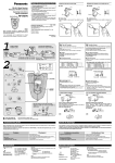
Video board
Model AW-
P
Before attempting to connect, operate or adjust this product, please
read these instructions completely.
Printed in Japan
VQT9563
F1101W @
P
CAUTION
RISK OF ELECTRIC SHOCK
DO NOT OPEN
CAUTION: TO REDUCE THE RISK OF ELECTRIC SHOCK,
DO NOT REMOVE COVER (OR BACK).
NO USER SERVICEABLE PARTS INSIDE.
REFER TO SERVICING TO QUALIFIED SERVICE PERSONNEL.
The lightning flash with arrowhead symbol, within an equilateral triangle,
is intended to alert the user to the presence of uninsulated “dangerous
voltage” within the product’s enclosure that may be of sufficient
magnitude to constitute a risk of electric shock to persons.
The exclamation point within an equilateral triangle is intended to alert the
user to the presence of important operating and maintenance (service)
instructions in the literature accompanying the appliance.
WARNING:
TO REDUCE THE RISK OF FIRE OR SHOCK HAZARD, DO NOT
EXPOSE THIS EQUIPMENT TO RAIN OR MOISTURE.
CAUTION:
TO REDUCE THE RISK OF FIRE OR SHOCK HAZARD AND ANNOYING
INTERFERENCE, USE THE RECOMMENDED ACCESSORIES ONLY.
FCC Note:
This device complies with Part 15 of the FCC Rules. To assure continued
compliance follow the attached installation instructions and do not make any
unauthorized modifications.
This equipment has been tested and found to comply with the limits for a class A
digital device, pursuant to Part 15 of the FCC Rules. These limits are designed to
provide reasonable protection against harmful interference when the equipment is
operated in a commercial environment. This equipment generates, uses, and can
radiate radio frequency energy and, if not installed and used in accordance with the
instruction manual, may cause harmful interference to radio communications.
Operation of this equipment in a residential area is likely to cause harmful
interference in which case the user will be required to correct the interference at his
own expense.
indicates safety information.
2
Contents
Introduction . . . . . . . . . . . . . . . . . . . . . . .3
Precautions for use . . . . . . . . . . . . . . . .3
Installing additional video boards . . . .4
Inserting an optional card . . . . . . . . . . .5
Specifications . . . . . . . . . . . . . . . . . . . . .6
Introduction
This is an additional video board which is designed exclusively for use with the AW-RP605
Multi-Function Controller.
Up to 4 of these video boards can be added to the AW-RP605 Multi-Function Controller,
thereby making it possible to connect 5 video boards in all.
Precautions for use
O Turn off the power before connecting or disconnecting the cable!
Before connecting or disconnecting the cable, ensure that the power is turned off.
O Handle the board carefully!
Do not drop the board or subject it to strong shock. Doing so may cause malfunctioning
or accidents.
O Use the board in temperatures of between 14°F (–10°C) and 113°F (+45°C)!
Avoid using the board at temperatures below 14°F (–10°C) or above 113°F (+45°C) as
the internal parts may be adversely affected.
Refer to the Operating Instructions of the AW-RP605 Multi-Function Controller for
further details on how to connect this board.
3
Installing additional video boards
(The installation work must be performed by your dealer without fail.)
The multi-function controller AW-RP605 comes with four slots for installing additional video
boards.
By adding the AW-PB605 video boards, up to five pan-tilt head systems can be controlled.
Before adding a board to the multi-function controller
O Set the power switches of all components to the OFF position, and disconnect the
power cords from the power outlets.
O Release the static carried in the body of the person to perform the installation.
Installation can be performed more safely if an anti-static wrist strap is worn.
Touching the board without first releasing this static may cause malfunctioning.
O Do not allow the metal part of the board come in contact with any other metal parts.
1. Remove the two screws and take off the blank panel.
2. Align the AW-PB605 video board with the guides, and insert it.
Push it in all the way.
3. Attach the board securely using the two screws.
Guides
Refer to the Operating Instructions of the AW-RP605 Multi-Function Controller for
further details on how to connect this board.
4
Inserting an optional card
(The installation work must be performed by your dealer without fail.)
The AW-PB605 video board comes with a slot into which an optional card (optional
accessory) for additional functions can be inserted.
ORGB card (AW-PB302)
OSDI card (AW-PB304)
OSVGA convert card (AW-PB307)
OWeb card (AW-PB309)
Before inserting an optional card
O Set the power switches of all components to the OFF position, and disconnect the
power cords from the power outlets.
O Release the static carried in the body of the person to perform the installation.
Installation can be performed more safely if an anti-static wrist strap is worn.
Touching the card without first releasing this static may cause malfunctioning.
O Do not allow the metal part of the card come in contact with any other metal parts.
1. Remove the two screws, followed by the blank panel.
2. Align the optional card with the guides and insert it. Push it in all the way.
3. Attach the card securely using the two screws.
To remove the optional card, insert a flat-head screwdriver or similar tool as shown in the
figure on the right, and pull out the card in the direction shown by the arrow.
5
Specifications
$ Output connectors
Power supply: DC 10.8 V to DC 16 V
Power consumption: 4.8 W
G/L OUT connector
BNC, 75Ω output
Connecting cable:
BELDEN 8281,
max. 3,280 feet (1,000 meters)
VIDEO/Y OUT, Pr OUT, Pb OUT
BNC a3, 75Ω output, 7.5% setup
Composite:
Y
= 100 IRE
Sync = 40 IRE
Burst = 40 IRE
Component:
Y
= 0.714 V
Sync = 0.286 V
Pr/Pb = 0.700 V
(Cable compensation must be
adjusted.)
indicates safety information.
Ambient operating temperature
14°F to 113°F (–10°C to +45°C)
Storage temperature
–4°F to +140°F (–20°C to +60°C)
Ambient operating humidity
30% to 90% (no condensation)
Weight
1.034 lb (0.47 kg)
Dimensions (WaHaD)
4 5/8˝a2 3/16˝a5 1/2˝
(117a55a139 mm)
$ Input connectors
VIDEO/Y IN, Pr IN, Pb IN
BNC a3, 75Ω termination, 7.5%
setup
Composite:
Y
= 100 IRE
Sync = 40 IRE
Burst = 40 IRE
Component:
Y
= 0.714 V
Sync = 0.286 V
Pr/Pb = 0.700 V
$ Other
OPTION card slot
Card supported:
AW-PB302, AW-PB304,
AW-PB307, AW-PB309
6
PANASONIC BROADCAST & TELEVISION SYSTEMS COMPANY
DIVISION OF MATSUSHITA ELECTRIC CORPORATION OF AMERICA
Executive Office:
3330 Cahuenga Blvd W., Los Angeles, CA 90068 (323) 436-3500
EASTERN ZONE:
One Panasonic Way 4E-7, Secaucus, NJ 07094 (201) 348-7621
Southeast Region:
1225 Northbrook Parkway, Ste 1-160, Suwanee, GA 30024 (770) 338-6835
Central Region:
1707 N Randall Road E1-C-1, Elgin, IL 60123 (847) 468-5200
WESTERN ZONE:
3330 Cahuenga Blvd W., Los Angeles, CA 90068 (323) 436-3500
Government Marketing Department:
52 West Gude Drive, Rockville, MD 20850 (301) 738-3840
Broadcast PARTS INFORMATION & ORDERING:
9:00 a.m. – 5:00 p.m. (EST) (800) 334-4881/24 Hr. Fax (800) 334-4880
Emergency after hour parts orders (800) 334-4881
TECHNICAL SUPPORT:
Emergency 24 Hour Service (800) 222-0741
Panasonic Canada Inc.
5770 Ambler Drive, Mississauga, Ontario L4W 2T3 (905) 624-5010
Panasonic de Mexico S.A. de C.V.
Av angel Urraza Num. 1209 Col. de Valle 03100 Mexico, D.F. (52) 1 951 2127
Panasonic Sales Company
Division of Matsushita Electric of Puerto Rico Inc.
San Gabriel Industrial Park, 65th Infantry Ave., Km. 9.5, Carolina, Puerto Rico 00630 (787) 750-4300
Plaque vidéo
Modèle AW-
Avant de raccorder, de faire fonctionner ou de régler l’appareil,
lire attentivement tout ce manuel.
P
ATTENTION
RISQUE DE CHOCS ÉLECTRIQUES
NE PAS OUVRIR
ATTENTION: AFIN DE PRÉVENIR LE RISQUE DE CHOCS ÉLECTRIQUES,
NE PAS RETIRER LES VIS.
TOUTE RÉPARATION DEVRAIT ÊTRE CONFIÉE À UN PERSONNEL COMPÉTENT.
Le symbole de l’éclair dans un triangle équilatéral indique la présence
d’une tension suffisamment élevée pour engendrer un risque de chocs
électriques.
Le point d’exclamation dans un triangle équilatéral indique que le manuel
d’instructions inclus avec l’appareil contient d’importantes
recommandations quant au fonctionnement et à l’entretien de ce dernier.
MISE EN GARDE:
AFIN DE PRÉVENIR TOUT RISQUE D’INCENDIE OU DE CHOCS
ÉLECTRIQUES, ÉVITER D’EXPOSER CET APPAREIL À LA PLUIE OU À
UNE HUMIDITÉ EXCESSIVE.
ATTENTION:
AFIN DE PRÉVENIR TOUT RISQUE D’INCENDIE, DE CHOCS
ÉLECTRIQUES OU D’INTERFÉRENCES, N’UTILISER QUE LES
ACCESSOIRES RECOMMANDÉS.
indique les consignes de sécurité.
–2–
Table des matières
Introduction . . . . . . . . . . . . . . . . . . . . . . .3
Précautions de fonctionnement . . . . . .3
Installation de plaques vidéo
additionnelles . . . . . . . . . . . . . . . . . . . . .4
Insertion d’une plaque vendue
séparément . . . . . . . . . . . . . . . . . . . . . . .5
Données techniques . . . . . . . . . . . . . . .6
Introduction
Cette plaque est une plaque vidéo additionnelle conçue exclusivement pour le
coordonnateur multi-fonctions AW-RP605.
Il est possible d’ajouter au maximum 4 de ces plaques vidéo dans le coordonnateur multifonctions AW-RP605, ce qui permet de raccorder 5 plaques vidéo au total.
Précautions de fonctionnement
O Couper le contact avant de raccorder ou de débrancher le câble!
Avant de raccorder ou de débrancher le câble, bien vérifier que le contact est coupé.
O Manipuler la plaque avec précaution!
Ne pas faire tomber la plaque ni la soumettre à un choc violent. Cela risquerait de
provoquer un mauvais fonctionnement ou des accidents.
O Utiliser la plaque à une température comprise entre –10°C et +45°C (14°F et
113°F)!
Ne pas utiliser la plaque à des températures inférieures à –10°C (14°F) et supérieures à
+45°C (113°F), car cela pourrait affecter les pièces internes.
Pour les détails sur le raccordement de la plaque, voir le manuel d’utilisation du
coordonnateur multi-fonctions AW-RP605.
–3–
Installation de plaques vidéo additionnelles
(L’installation doit être effectuée exclusivement par le détaillant.)
Le coordonnateur multi-fonctions AW-RP605 est équipé de quatre emplacements pour
l’installation de plaques vidéo additionnelles.
En ajoutant des plaques vidéo AW-PB605, il sera possible de piloter un maximum de cinq
systèmes de tête panoramique.
Avant d’ajouter une plaque dans le coordonnateur multi-fonctions
O Placer les interrupteurs de chacun des appareils à la position OFF, et débrancher
les fils d’alimentation des prises secteur.
O Avant de procéder à l’installation, libérer toute électricité statique qui aurait pu
s’accumuler dans le corps.
L’installation s’effectuera avec une plus grande sécurité en portant un bracelet antiélectricité statique.
Le fait de toucher la plaque sans s’être au préalable déchargé de toute électricité
statique risque de provoquer un mauvais fonctionnement.
O Veiller à ce qu’aucune pièce métallique de la plaque n’entre en contact avec une
autre pièce métallique.
1. Retirer les deux vis et retirer le panneau vide.
2. Aligner la plaque vidéo AW-PB605 sur les guides, puis l’insérer.
Insérer la plaque à fond.
3. Fixer solidement la plaque avec les deux vis.
Guides
Pour les détails sur le raccordement de la plaque, voir le manuel d’utilisation du
coordonnateur multi-fonctions AW-RP605.
–4–
Insertion d’une plaque vendue séparément
(L’installation doit être effectuée exclusivement par le détaillant.)
La plaque vidéo AW-PB605 est équipée d’un emplacement prévu pour l’insertion d’une
plaque vendue séparément (accessoire vendu séparément) afin de bénéficier de fonctions
additionnelles.
OPlaque RGB (AW-PB302)
OPlaque SDI (AW-PB304)
OPlaque de conversion SVGA (AW-PB307)
OPlaque Web (AW-PB309)
Avant d’insérer une plaque vendue séparément
O Placer les interrupteurs de chacun des appareils à la position OFF, et débrancher
les fils d’alimentation des prises secteur.
O Avant de procéder à l’installation, libérer toute électricité statique qui aurait pu
s’accumuler dans le corps.
L’installation s’effectuera avec une plus grande sécurité en portant un bracelet antiélectricité statique.
Le fait de toucher la plaque sans s’être au préalable déchargé de toute électricité
statique risque de provoquer un mauvais fonctionnement.
O Veiller à ce qu’aucune pièce métallique de la plaque n’entre en contact avec une
autre pièce métallique.
1. Retirer les deux vis, puis le panneau vide.
2. Aligner la plaque vendue séparément sur les guides, puis l’insérer. Insérer la plaque à
fond.
3. Fixer solidement la plaque avec les deux vis.
Pour retirer la plaque vendue séparément, insérer la lame d’un tournevis à tête plate ou
d’un outil similaire comme illustré à droite, et tirer sur la plaque dans la direction de la
flèche.
–5–
Données techniques
$ Connecteurs de sortie
Alimentation: 10,8 V c.c. à 16 V c.c.
Consommation: 4,8 W
Connecteur G/L OUT
BNC, sortie 75 Ω
Câble de raccordement:
BELDEN 8281,
1 000 mètres (3 280 pieds) max.
VIDEO/Y OUT, Pr OUT, Pb OUT
BNC a3,
BNC, sortie 75 Ω, établissement à
7,5%
Composites:
Y
= 100 IRE
Synchronisation = 40 IRE
Salve
= 40 IRE
Composantes:
Y
= 0,714 V
Synchronisation = 0,286 V
Pr/Pb
= 0,700 V
(Il faudra effectuer une
compensation de câble.)
indique les consignes de sécurité.
Température
de
fonctionnement
ambiante
–10°C à +45°C (14°F à 113°F)
Température de rangement
–20°C à +60°C (–4°F à +140°F)
Humidité de fonctionnement ambiante
30% à 90% max. (sans condensation)
Poids
0,47 kg (1,034 lb)
Dimensions (L x H x P)
117a55a139 mm
(4 5/8˝a2 3/16˝a5 1/2˝)
$ Connecteurs d’entrée
VIDEO/Y IN, Pr IN, Pb IN
BNC a3,
terminaison 75 Ω, établissement à
7,5%
Composites:
Y
= 100 IRE
Synchronisation = 40 IRE
Salve
= 40 IRE
Composantes:
Y
= 0,714 V
Synchronisation = 0,286 V
Pr/Pb
= 0,700 V
$ Divers
–6–
Emplacement pour plaque OPTION
Plaques supportées:
AW-PB302, AW-PB304,
AW-PB307, AW-PB309
Panasonic Canada Inc.
5770 Ambler Drive, Mississauga, Ontario L4W 2T3 (905) 624-5010