1
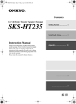
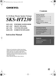
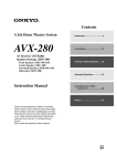
HTP-240.fm Page 1 Wednesday, December 3, 2003 9:30 AM
Contents
5.1 Ch Home Theater Speaker Package
HTP-240
Getting Started
Important Safeguards ..................... 2
Precautions ..................................... 3
Introduction ..................................... 4
Package Contents ........................... 4
Getting to know Your Speaker
Package ........................................ 5
6.1 Ch Home Theater Speaker Package
SKS-HT240
Installing & Using
Various Mounting Methods ............ 6
Connecting the Speakers ............... 8
About Home Theater ....................... 9
Adjustment .................................... 10
Instruction Manual
Appendix
Caring for Your Speakers.............. 10
Troubleshooting ............................ 11
Specifications................................ 12
Thank you for purchasing an Onkyo home theater
speaker package. Please read this manual thoroughly
before using your new speakers. Following the
instructions in this manual will enable you to obtain
optimum performance and listening enjoyment from
your speaker package.
Please retain this manual for future reference.
En
HTP-240.fm Page 2 Wednesday, December 3, 2003 9:30 AM
WARNING:
TO REDUCE THE RISK OF FIRE OR ELECTRIC
SHOCK, DO NOT EXPOSE THIS APPLIANCE TO
RAIN OR MOISTURE.
CAUTION:
TO REDUCE THE RISK OF ELECTRIC SHOCK, DO
NOT REMOVE COVER (OR BACK). NO USERSERVICEABLE PARTS INSIDE. REFER SERVICING
TO QUALIFIED SERVICE PERSONNEL.
WARNING
AVIS
RISK OF ELECTRIC SHOCK
DO NOT OPEN
RISQUE DE CHOC ELECTRIQUE
NE PAS OUVRIR
The lightning flash with arrowhead symbol, within an
equilateral triangle, is intended to alert the user to
the presence of uninsulated “dangerous voltage”
within the product’s enclosure that may be of
sufficient magnitude to constitute a risk of electric
shock to persons.
The exclamation point within an equilateral triangle is
intended to alert the user to the presence of important
operating and maintenance (servicing) instructions in
the literature accompanying the appliance.
Important Safeguards
1. Read Instructions – All the safety and operating
instructions should be read before the appliance is
operated.
2. Retain Instructions – The safety and operating
instructions should be retained for future reference.
3. Heed Warnings – All warnings on the appliance and
in the operating instructions should be adhered to.
4. Follow Instructions – All operating and use
instructions should be followed.
5. Cleaning – Unplug the appliance from the wall outlet before cleaning. The appliance should be cleaned
only as recommended by the manufacturer.
6. Attachments – Do not use attachments not recommended by the appliance manufacturer as they may
cause hazards.
7. Water and Moisture – Do not use the appliance near
water –for example, near a bath tub, wash bowl,
kitchen sink, or laundry tub; in a wet basement; or
near a swimming pool; and the like.
8. Accessories – Do not place the appliance on an
unstable cart, stand, tripod, bracket, or table. The
appliance may fall, causing serious injury to a child
or adult, and serious damage to the appliance. Use
only with a cart, stand, tripod, bracket, or table recommended by the manufacturer, or sold with the
appliance. Any mounting of the appliance should
follow the manufacturer’s instructions, and should
use a mounting accessory recommended by the
manufacturer.
PORTABLE CART WARNING
9. An appliance and cart combination should be moved
with care. Quick stops,
excessive force, and uneven
surfaces may cause the
appliance and cart combination to overturn.
S3125A
10. Ventilation – Slots and openings in the cabinet are
provided for ventilation and to ensure reliable operation of the appliance and to protect it from overheating, and these openings must not be blocked or
covered. The openings should never be blocked by
placing the appliance on a bed, sofa, rug, or other
similar surface. The appliance should not be placed
in a built-in installation such as a bookcase or rack
unless proper ventilation is provided. There should
be free space of at least 20 cm (8 in.) and an opening behind the appliance.
2
11. Power Sources – The appliance should be operated
only from the type of power source indicated on the
marking label. If you are not sure of the type of
power supply to your home, consult your appliance
dealer or local power company.
12. Grounding or Polarization – The appliance may
be equipped with a polarized alternating current line
plug (a plug having one blade wider than the other).
This plug will fit into the power outlet only one way.
This is a safety feature. If you are unable to insert
the plug fully into the outlet, try reversing the plug.
If the plug should still fail to fit, contact your electrician to replace your obsolete outlet. Do not defeat
the safety purpose of the polarized plug.
13. Power-Cord Protection – Power-supply cords
should be routed so that they are not likely to be
walked on or pinched by items placed upon or
against them, paying particular attention to cords at
plugs, convenience receptacles, and the point where
they exit from the appliance.
14. Lightning – For added protection for the appliance
during a lightning storm, or when it is left unattended and unused for long periods of time, unplug
it from the wall outlet and disconnect the antenna or
cable system. This will prevent damage to the appliance due to lightning and power-line surges.
15. Overloading – Do not overload wall outlets, extension cords, or integral convenience receptacles as
this can result in a risk of fire or electric shock.
16. Object and Liquid Entry – Never push objects of
any kind into the appliance through openings as
they may touch dangerous voltage points or shortout parts that could result in a fire or electric shock.
Never spill liquid of any kind on the appliance.
17. Servicing – Do not attempt to service the appliance
yourself as opening or removing covers may expose
you to dangerous voltage or other hazards. Refer all
servicing to qualified service personnel.
HTP-240.fm Page 3 Wednesday, December 3, 2003 9:30 AM
Important Safeguards—Continued
18. Damage Requiring Service – Unplug the appliance form the wall outlet and refer servicing to
qualified service personnel under the following conditions:
A. When the power-supply cord or plug is damaged,
B. If liquid has been spilled, or objects have fallen
into the appliance,
C. If the appliance has been exposed to rain or
water,
D. If the appliance does not operate normally by
following the operating instructions. Adjust only
those controls that are covered by the operating
instructions as an improper adjustment of other
controls may result in damage and will often
require extensive work by a qualified technician
to restore the appliance to its normal operation,
E. If the appliance has been dropped or damaged in
any way, and
F. When the appliance exhibits a distinct change in
performance – this indicates a need for service.
19. Replacement Parts – When replacement parts are
required, be sure the service technician has used
replacement parts specified by the manufacturer or
have the same characteristics as the original part.
Unauthorized substitutions may result in fire, electric shock, or other hazards.
20. Safety Check – Upon completion of any service or
repairs to the appliance, ask the service technician to
perform safety checks to determine that the appliance
is in proper operation condition.
21. Wall or Ceiling Mounting – The appliance should
be mounted to a wall or ceiling only as recommended by the manufacturer.
22. Heat – The appliance should be situated away from
heat sources such as radiators, heat registers, stoves,
or other appliances (including amplifiers) that produce heat.
23. Liquid Hazards – The appliance should not be
exposed to dripping or splashing and no objects
filled with liquids, such as vases should be placed
on the appliance.
Precautions
1. Mounting
Mount the speakers as explained in this manual. Don’t
use the front or surround speakers without their bases or
optional stands as damage or injury may result.
2. AC Fuse
The fuse is located inside the chassis and is not userserviceable. If power does not come on, contact your Onkyo
authorized service station.
3. Care
From time to time you should wipe off the front and rear
panels and the cabinet with a soft cloth. For heavier dirt,
dampen a soft cloth in a weak solution of mild detergent
and water, wring it out dry, and wipe off the dirt. Following this, dry immediately with a clean cloth. Do not use
rough material, thinners, alcohol or other chemical solvents or cloths since these may damage the finish or
remove the panel lettering.
Use a vacuum cleaner to remove dust from hard-to-reach
grilles.
4. Power
WARNING
BEFORE PLUGGING IN THE UNIT FOR THE
FIRST TIME, READ THE FOLLOWING SECTION
CAREFULLY.
The voltage of the available power supply differs
according to country or region. Be sure that the power
supply voltage of the area where this unit will be used
meets the required voltage (e.g., AC 120 V, 60 Hz) written on the rear panel.
For Canadian models
For models having a power cord with a polarized plug:
CAUTION: TO PREVENT ELECTRIC SHOCK,
MATCH WIDE BLADE OF PLUG TO WIDE SLOT,
FULLY INSERT.
Modèle pour les Canadien
Sur les modèles dont la fiche est polarisee:
ATTENTION: POUR ÉVITER LES CHOCS ÉLECTRIQUES, INTRODUIRE LA LAME LA PLUS
LARGE DE LA FICHE DANS LA BORNE CORRESPONDANTE DE LA PRISE ET POUSSER
JUSQU’AU FOND.
3
HTP-240.fm Page 4 Wednesday, December 3, 2003 9:30 AM
Introduction
The HTP-240’s and SKS-HT240’s stylish enclosures are made of aluminum and their slim design makes them ideal for
use with LCD and plasma TVs.
HTP-240
SKS-HT240
The SKS-HT240 is a 6.1-channel speaker package consisting of front left and right speakers, a center speaker,
surround left and right speakers, a surround back
speaker, and a powered subwoofer. Simply connect the
speakers to your AV amp or receiver for superb surround
sound playback.
Speaker terminals and speaker cables are color-coded for
easy identification. Simply connect each speaker cable to
the same-colored speaker terminals.
The HTP-240 is a 5.1-channel speaker package consisting of front left and right speakers, a center speaker, surround left and right speakers, and a powered subwoofer.
It has been optimized for use with the Onkyo DR-S2.2
DVD Receiver, with which it will deliver superb surround sound playback.
Speaker terminals and speaker cables are color-coded for
easy identification. Simply connect each speaker cable to
the same-colored speaker terminals.
Package Contents
Make sure your box contains all of the items below. If anything is missing, contact the nearest Onkyo dealer.
• Front speakers
(SKF-240F)
• Spacers for wall mounting [×20]
(HTP-240 only)
• Setup sheet
(HTP-240 only)
• Speaker cable for front speakers
15 ft. (4.5 m)
(Red)
(White)
• Front speaker base fixing screws [×8]
• Front speaker bases
• Center speaker
(SKC-240C)
• Center speaker base
• Speaker cable for center speaker
10 ft. (3 m)
(Green)
• Surround speakers
(SKM-240S)
• Speaker cables for surround
speakers 30 ft. (9 m)
(Blue)
• Subwoofer
(SKW-240)
• RCA cable for subwoofer
connection
(Gray)
Items Supplied with SKS-HT240 Only
• Surround back speaker (SKB-240)
• Speaker cable for surround
back speaker 30 ft. (9 m)
(Brown)
4
• Spacers for wall
mounting [×24]
HTP-240.fm Page 5 Wednesday, December 3, 2003 9:30 AM
Getting to know Your Speaker Package
Subwoofer (SKW-240)
Front, Center & Surround Speakers
(SKF-240F, SKC-240C, SKM-240S,
SKB-240)
■ Front
3
2
1
1
■ Rear
OUTPUT
LEVEL
LINE
INPUT
MAX
MIN
4
2
3
To AC outlet
A STANDBY/ON indicator
Red:
Subwoofer in standby mode
Green: Subwoofer on
With the Auto Standby function, the SKW-240
automatically turns on when an input signal is
detected in Standby mode. When there’s no input
signal for about 20 minutes, the SKW-240 automatically enters Standby mode.
B OUTPUT LEVEL control
This control is used to adjust the volume of the subwoofer.
C LINE INPUT
This RCA input should be connected to the subwoofer preout on your DR-S2.2 DVD Receiver,
amp, or other receiver with supplied RCA cable.
Note:
The Auto Standby function turns the subwoofer on when
the input signal exceeds a certain level. If the Auto
Standby function does not work reliably, try slightly
increasing or decreasing the subwoofer output level on
your receiver or amp.
1 Speaker terminals
These push terminals are for connecting the speaker
to your DR-S2.2 DVD Receiver, amp, or other
receiver with the supplied speaker cables. The supplied speaker cables are color-coded for easy identification. Simply connect each cable to the samecolored positive speaker terminal.
2 Keyhole slots
These keyhole slots can be used to wall-mount the
speaker either horizontally or vertically.
3 Speaker mount/bracket inserts
These threaded inserts can be used to attach the
speaker either horizontally or vertically to a speaker
mount or bracket.
Note:
Use commercially available 1/4-inch machine
screws to attach the speaker to a speaker mount or
bracket.
4 Base/stand inserts (other than center
speaker)
These threaded inserts can be used to mount the
speaker on the supplied base (screws included) or an
optional Onkyo speaker stand (AS-240).
5
HTP-240.fm Page 6 Wednesday, December 3, 2003 9:30 AM
Various Mounting Methods
Front Speaker Bases
Wall Mounting
If you intend to stand the front speakers on the floor or
on a TV stand or AV stand, you should attach the supplied front speaker bases. To do this, align the mounting
holes in the base with base/stand inserts on the front
speaker’s rear panel, and secure by using four of the supplied fixing screws.
The front speakers, center speaker, surround speakers,
and surround back speaker (SKS-HT240 only) can easily be wall mounted by using the keyhole slots. To prevent the speaker from vibrating against the wall, attach
four of the supplied spacers to the keyhole fins on the
rear of each speaker.
■ Mounting vertically
To mount the front speakers, surround speakers, or surround back speaker (SKS-HT240 only) vertically, use
the keyhole slot shown to hang each speaker on a screw
that’s securely screwed into the wall.
Front speaker
2-9/16"
2-9/16"
4-7/8"
Keyhole slot for
vertical wall
mounting
Base/stand inserts
Spacers
Mounting holes
Center Speaker Base
Spacers
The center speaker base is for mounting the center
speaker horizontally. If you put it on a TV stand or AV
stand, aim it toward the listening position. The center
speaker should sit securely on the base. If it’s loose, try
resetting it.
Note:
• If you put the center speaker on the floor, take it off the
base and position it so that it’s facing slightly up
toward the listener’s ears.
Bottom
Surround/Surround Back speaker
2-9/16"
2-9/16"
Keyhole slot for
vertical wall
mounting
1-13/16"
Spacers
Base for horizontal
mounting
Spacers
Bottom
6
HTP-240.fm Page 7 Wednesday, December 3, 2003 9:30 AM
Various Mounting Methods—Continued
■ Mounting horizontally
To mount the center speaker horizontally, use the two
keyhole slots shown to hang each speaker on two screws
that are securely screwed into the wall.
Center speaker
Spacers
Keyhole slots for horizontal
wall mounting
Using Speaker Mounts/Brackets
Threaded inserts for 1/4-inch machine screws are provided on the rear of each speaker for wall-mounting with
commercially available speaker mounts and brackets.
Refer to the manual supplied with your mounts or brackets for installation details.
Spacers
2-9/16"
Use this hole if mounting
vertically
2-9/16"
4-7/8"
7-9/16"
4-7/8"
Caution:
A mounting screw’s ability to support a speaker depends
on how well it’s anchored to the wall. If you have hollow
walls, screw each mounting screw into a stud. If there are
no studs, or the walls are solid, use suitable wall anchors.
Use screws with a head diameter of 3/8 inch or less and
a shank diameter of 1/8 inch (or 4 mm) or less (No. 8 or
smaller). With hollow walls, use a cable/pipe detector to
check for any power cables or water pipes before making
any holes.
(We recommend that you consult a home installation
professional.)
Use this hole if mounting
horizontally
Note:
The portion of the screw that goes into the speaker’s
threaded insert should be between 1/5 and 3/8 of an inch
long.
Mount or bracket
Using the Optional Speaker Stands
Optional Onkyo speaker stands (AS-240) are available
for the front left and right and surround left and right
speakers. To attach a speaker to a stand, align the mounting holes in the stand with those on the speaker’s rear
panel, and secure by using four of the supplied fixing
screws.
1/4"
1/5"–3/8"
7
HTP-240.fm Page 8 Wednesday, December 3, 2003 9:30 AM
Connecting the Speakers
Read the following before connecting your speakers:
• Turn off your amp before making any connections.
• The nominal impedance of these speakers is 8 Ω. Use
only an amp that supports this impedance.
• Pay close attention to speaker wiring polarity. Connect
positive (+) terminals to only positive (+) terminals,
and negative (–) terminals to only negative (–) terminals. If the speakers are wired incorrectly, the sound
will be out of phase and will sound unnatural.
• Be careful not to short the positive and negative wires. Doing so
may damage your amp.
HTP-240 & DR-S2.2 Receiver Hookup
Front right
speaker
Front left
speaker
Center
speaker
Green
Red
White
REMOTE
CONTROL
ANTENNA
MON
OUT
OUT
IN
IN
MON
OUT
OUT
IN
OUT
IN
IN
OUT
IN
IN
2 ––VIDEO –– 1
VIDEO 2
VIDEO 1
VIDEO 2
DIGITAL
OUTPUT
IN
COMPONENT VIDEO OUTPUT
PB
PR
Y
DIGITAL INPUT
VIDEO 1
OPT
OPT
COAX
VIDEO
S VIDEO
AM
SUB
WOOFER
PRE OUT
A
L
R
B
SURROUND CENTER
SPEAKERS SPEAKER
L
R
L
L
AUDIO
AUDIO
FM
75
FRONT SPEAKERS
R
R
VIDEO 1
VIDEO2
CDR/PC
TAPE
MD/HD
TV/LINE
Blue
Connecting the Speaker Cables
Gray
1
Use the cables to connect each speaker’s
input terminals to the corresponding
speaker output terminals on your amp.
To make a connection, while
pressing the terminal lever,
insert the wire into the hole, and
then release the lever.
Make sure that the terminals are
gripping the bare wires, not the insulation.
Tip:
• You can make cable identification easier by attaching
the color-coded speaker labels supplied with the
Onkyo DR-S2.2 DVD Receiver or other Onkyo amp
or receiver to the positive (+) side of each speaker
cable, in accordance with the following table.
Speaker terminal (+)
Color
Front left
White
Front right
Red
Center
Green
Surround left
Blue
LINE
INPUT
Surround
right speaker
Powered
subwoofer
SKS-HT240 & 6-channel AV Amp Hookup
Onkyo AV receiver used in this example.
Center
speaker
Front right
speaker
Red
ANTENNA
AM
CAUTION: SPEAKER IMPEDANCE
6 OHMS MIN. /SPEAKER
ZONE 2
SPEAKERS
OUTPUT
INPUT 1
Gray
Surround back (SKS-HT240 only)
Brown
ZONE 2
LINE OUT
IN
2
OPTICAL
1
IN
OPTICAL
L
R
R
AC OUTLETS
R
PR
OUT
CENTER
SPEAKER
SURROUND
SPEAKERS
FRONT
SPEAKERS
L
L
PB
DIGITAL
White
FM 75
COMPONENT VIDEO
INPUT 2
Front left
speaker
Green
Y
Surround right
Surround
left speaker
VIDEO 3
VIDEO 2
VIDEO 1
IN
OUT
IN
OUT
IN
OUT
IN
OUT
IN
REMOTE
CONTROL
DVD
IN
MONITOR
OUT
FRONT
SURR
COAXIAL
ZONE 2
V
12 V
TRIGGER
OUT
PRE OUT
S
IR IN
SURROUND BACK
SPEAKER
AC 120 V
60 Hz
SWITCHED
TOTAL 120W 1A MAX.
SUBWOOFER
AV RECEIVER
MODEL NO. TX-SR 601
TAPE
CD
IN
IN
OUT
IN
CENTER
L
L
R
R
CD
TAPE
VIDEO 3
VIDEO 2
VIDEO 1
DVD
SUB
WOOFER
Connecting the Subwoofer
1
Using the supplied RCA cable, connect
the subwoofer’s LINE INPUT to your amp’s
SUBWOOFER PREOUT.
Blue
Gray
Brown
LINE
INPUT
Surround
right speaker
8
Powered
subwoofer
Surround
left speaker
Surround
back speaker
HTP-240.fm Page 9 Wednesday, December 3, 2003 9:30 AM
About Home Theater
Enjoying Home Theater
The HTP-240/SKS-HT240’s great sound means that you can enjoy surround sound with a real sense of movement in
your own home—just like being in a movie theater or concert hall.
Center speaker
This speaker enhances the front left and right
speakers, making sound movements distinct and
providing a full sound image. In movies it’s used
mainly for dialog.
Position it close to your TV facing forward at
about ear level, or at the same height as the front
left and right speakers.
Front left and right speakers
These output the overall sound. Their role in a home theater
is to provide a solid anchor for the sound image. They should
be positioned facing the listener at about ear level, and equidistant from the TV. Angle them inward so as to create a
triangle, with the listener at the apex.
Right
Subwoofer
The subwoofer handles the bass
sounds of the LFE (Low-Frequency Effects) channel. The volume and quality of the bass output
from your subwoofer will depend
on its position, the shape of your
listening room, and your listening
position. In general, a good bass
sound can be obtained by installing the subwoofer in a front corner, or at one-third the width of the
wall, as shown.
Left
Surround left and right speakers
These speakers are used for precise
sound positioning and to add realistic
ambience. Position them at the sides
of the listener, or slightly behind,
about 2–3 feet (60–100 cm) above
ear level. Ideally they should be equidistant from the listener.
Corner
1/3 room
length
Surround back speaker (SKS-HT240 only)
This speaker further enhances the realism of surround
sound and improves sound localization behind the listener. The surround-back speaker should be installed
behind the listener also at 2–3 ft. (60–100 cm) above ear
level. Make sure that the listening position is within the
range of the speaker.
9
HTP-240.fm Page 10 Wednesday, December 3, 2003 9:30 AM
Caring for Your Speakers
Adjustment
Setting the Subwoofer Level
To set the level of the subwoofer, use the OUTPUT
LEVEL control. Set it so that bass sounds are evenly balanced with the treble sounds from the other speakers.
Because our ears are less sensitive to very low bass
sounds, there’s a temptation to set the level of the subwoofer too high. As a rule of thumb, set the subwoofer
level to what you think is the optimal level, and then back
it off slightly.
OUTPUT
LEVEL
MIN
MAX
• The speaker cabinets are made out of aluminum and
are therefore sensitive to extreme temperatures and
humidity, do not put them in locations subject to direct
sunlight or in humid places, such as near an air conditioner, humidifier, bathroom, or kitchen.
• Do not put water or other liquids close to the speakers.
If liquid is spilled over the speakers, the drive units
may be damaged.
• As explained in this manual, mount the speakers on a
wall, on the supplied bases, or on the optional stands,
otherwise, they may fall, causing personal injury or
damage to the speakers.
• Speakers with bases should only be placed on sturdy,
flat surfaces that are free from vibration. Putting them
on uneven or unstable surfaces, where they may fall
and cause damage, will affect the sound quality.
Using Close to a TV or Computer
Subwoofer Level Set OK
Overall response
Level
Placement
Repsonse of other speakers
Subwoofer response
Frequency
Subwoofer Level Set Incorrectly
Subwoofer level too high
Level
Subwoofer level too low
TVs and computer monitors are magnetically sensitive
devices and as such are likely to suffer discoloration or
picture distortion when conventional speakers are placed
nearby. To prevent this, the HTP-240/SKS-HT240 speakers feature internal magnetic shielding. In some situations, however, discoloration may still be an issue, in
which case you should turn off your TV or monitor, wait
15 to 30 minutes, and then turn it back on again. This normally activates the degaussing function, which neutralizes the magnetic field, thereby removing any
discoloration effects. If discoloration problems persist,
try moving the speakers away from your TV or monitor.
Note that discoloration can also be caused by a magnet or
demagnetizing tool that’s too close to your TV or monitor.
The HTP-240/SKS-HT240 speakers contain strong
magnets, so do not put magnetic or iron objects such as
screwdrivers close to them. If you do, the object may be
attracted to the magnets, causing personal injury or damage to a speaker cone.
Operating Precautions
Frequency
10
The HTP-240/SKS-HT240 speakers can handle the
specified input power when used for normal music
reproduction. If any of the following signals are fed to
them, even if the input power is within the specified rating, excessive current may flow in the speaker coils,
causing burning or wire breakage:
1. Interstation noise from an untuned FM radio.
2. Sound from fast-forwarding a cassette tape.
3. High-pitched sounds generated by an oscillator, electronic musical instrument, and so on.
4. Amplifier oscillation.
5. Special test tones from audio test CDs and so on.
6. Thumps and clicks caused by connecting or disconnecting audio cables (Always turn off your amplifier
before connecting or disconnecting cables.)
7. Microphone feedback.
HTP-240.fm Page 11 Wednesday, December 3, 2003 9:30 AM
Troubleshooting
Symptom
There’s no sound coming
from certain speakers?
The subwoofer does not
turn on?
The subwoofer produces
no sound?
The subwoofer produces
hardly any sound?
A humming sound can be
heard from the subwoofer?
Possible cause
Remedy
The speaker cables are not connected properly.
Check the speaker cables and correct as necessary.
HTP-240: The number of speaker channels is
not set to 5ch on the DR-S2.2.
Set the number of speaker channels to 5ch.
SKS-HT240: On the amp or receiver, the
Speaker Configuration settings for those
speakers are set to either None or No. Or, the
number of speaker channels is not set to 6ch.
Check the Speaker Configuration settings and
make sure that the speakers are set to something
other than None or No. Or set the number of
speaker channels to 6ch.
The power plug is not fully inserted into the
wall outlet.
Insert the power plug fully into the wall outlet.
The OUTPUT LEVEL control is set to minimum.
Turn up the OUTPUT LEVEL control.
The RCA cable is not properly connected to
the subwoofer’s LINE INPUT.
Make sure that the RCA cable is properly connected to the subwoofer’s LINE INPUT.
The level of the input signal was too low and
the subwoofer entered Standby mode.
Slightly increase the subwoofer preout output level
on your amp.
HTP-240: On the DR-S2.2 Receiver, the subwoofer mode is set to SW Off.
Set the subwoofer mode to something other than
SW Off.
SKS-HT240: On your amp or receiver, the
speaker setting is set to Subwoofer No, or the
subwoofer mode is set to Subwoofer Off.
Check the settings on your amp or receiver.
The source material contain little or no bass
content.
Choose source material with more bass content.
The RCA cable is not properly connected to
the subwoofer’s LINE INPUT.
Make sure that the RCA cable is properly connected to the subwoofer’s LINE INPUT.
External interference from a TV or other electronic device is being picked up.
Move the subwoofer and RCA cable away from the
interference source. Make sure your audio system
is grounded properly.
11
HTP-240.fm Page 12 Wednesday, December 3, 2003 9:30 AM
Specifications
■ Powered Subwoofer (SKW-240)
Type:
Bass reflex with built-in
power amplifier
Input sensitivity/impedance: 220 mV / 15 kΩ
Maximum output power:
150 W Dynamic
Frequency response:
27 Hz–150 Hz
SN ratio:
70 dB
Cabinet capacity:
38.5 L
Dimensions (W × H × D): 10-13/16" × 20-3/8" × 16-3/16"
(275 × 518 × 411 mm)
Weight:
30.9 lbs. (14 kg)
Drive unit:
8" cone woofer
Power supply:
AC 120 V, 60 Hz
Power consumption:
75 W
Other:
Auto Standby function
■ Center Speaker (SKC-240C)
Type:
2-way bass reflex center
speaker
Impedance:
8Ω
Maximum input power:
100 W
Output sound pressure level: 82 dB/W/m
Frequency response:
65 Hz–35 kHz
Crossover frequency:
5 kHz
Cabinet capacity:
2.6 L
Dimensions (W × H × D): 17-5/16" × 5-1/8" × 3-9/16"
(439 × 130 × 91 mm)
Weight:
5.1 lbs. (2.45 kg)
Speaker:
3-1/8" cone woofer × 2
1" balanced-dome
tweeter
Other:
Magnetic shielding
■ Front Speaker (SKF-240F)
Type:
2-way bass reflex front
speaker
Impedance:
8Ω
Maximum input power:
100 W
Output sound pressure level: 82 dB/W/m
Frequency response:
55 Hz–35 kHz
Crossover frequency:
5 kHz
Cabinet capacity:
3L
Dimensions (W × H × D): 5-1/8" × 19-11/16" × 3-9/16"
(130 × 500 × 91 mm)
Weight:
5.5 lbs. (2.5 kg)
Drive unit:
3-1/8" cone woofer × 2
1" balanced-dome
tweeter
Other:
Magnetic shielding
■ Surround Speaker (SKM-240S/SKB-240)
Type:
2-way bass reflex
surround/surround back
speaker
Impedance:
8Ω
Maximum input power:
100 W
Output sound pressure level: 80 dB/W/m
Frequency response:
65 Hz–35 kHz
Crossover frequency:
6.5 kHz
Cabinet capacity:
2L
Dimensions (W × H × D): 5-1/8" × 13-3/8" × 3-9/16"
(130 × 340 × 91 mm)
Weight:
3.5 lbs. (1.6 kg)
Speaker:
3-1/8" cone woofer
1" balanced-dome
tweeter
Other:
Magnetic shielding
Specifications and appearance are subject to change
without prior notice.
Sales & Product Planning Div. : 2-1, Nisshin-cho, Neyagawa-shi, OSAKA 572-8540, JAPAN
Tel: 072-831-8023 Fax: 072-831-8124
ONKYO U.S.A. CORPORATION
18 Park Way, Upper Saddle River, N.J. 07458, U.S.A.
Tel: 201-785-2600 Fax: 201-785-2650 http://www.onkyousa.com
ONKYO EUROPE ELECTRONICS GmbH
Liegnitzerstrasse 6, 82194 Groebenzell, GERMANY
Tel: +49-8142-4401-0 Fax: +49-8142-4401-555 http://www.onkyo.net
ONKYO CHINA LIMITED
Units 2102-2107, Metroplaza Tower I, 223 Hing Fong Road, Kwai Chung,
N.T., HONG KONG Tel: 852-2429-3118 Fax: 852-2428-9039
HOMEPAGE
http://www.onkyo.com/
SN 29343622
(C) Copyright 2003 ONKYO CORPORATION Japan. All rights reserved.
12
I0312-1