1
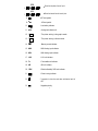
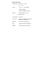
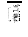
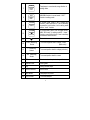
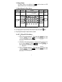
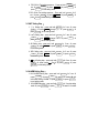
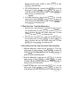
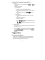
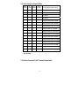
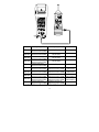
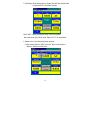
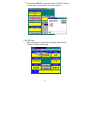
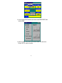
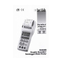
Title CONTENTS page 1. SAFETY INFORMATION ................................................................................................ 1 2. SPECIFICATION ............................................................................................................. 2 2-1 General Specification ........................................................................................... 2 2-2 Electrical Specification.......................................................................................... 5 3. PARTS & CONTROLS .................................................................................................... 6 3-1 The Name of Each Parts and Positions................................................................ 6 3-2 Power Status ........................................................................................................ 9 3-3 Quick Manual for Easy Set-up.............................................................................. 9 3-4 ACV、DCV and DCA Test Setting.......................................................................... 9 3-5 UNIT Setting Step .............................................................................................. 10 3-6 ALARM Setting Step........................................................................................... 10 3-7 Real Time Clock , Time/ Date Setting Step ........................................................ 11 3-8 Record/Print Start Time, Stop Time, Interval Time Setting Step......................... 11 3-9 Print Mode Setting Step...................................................................................... 12 3-10 Clear Record Step............................................................................................ 12 3-11 Disable Start、Stop、Intv and Setting Step.................................................... 12 3-12 Decimal Point Setting Step............................................................................... 12 3-13 Consecutive Record and Print Setting Step ..................................................... 12 3-14 Reset System Setting Step............................................................................... 12 3-15 Record / Print Start and Step Operation Method .............................................. 13 3-16 Memory Full Warning. ...................................................................................... 13 3-17 Alarm Print in Graphic Mode ............................................................................ 13 3-18 Scale Change in Graphic Mode........................................................................ 14 3-19 How to ConnectsTL-(A37) Analog Output Cable.............................................. 14 3-20 Setup Process Transducer (4-20mA) Mode ..................................................... 15 4. BATTERY & FUSE REPLACEMENT ........................................................................... 16 4-1 Battery Check & Replacement ........................................................................... 16 4-2 Fuse Replacement ............................................................................................. 16 4-3 Note.................................................................................................................... 16 5. DATALOGGING ............................................................................................................ 16 5-1 Software Installation ........................................................................................... 17 5-2 Default Settings .................................................................................................. 21 5-3 Meter Stand alone Operation ............................................................................. 36 5-4 Download Datalogger (Graphic Recorder èPC)............................................... 38 5-5 Data Conversion................................................................................................. 41 5-6 On-Line Operation with PC................................................................................. 45 1. SAFETY INFORMATION q Read the following safety information carefully before attempting to operate or service the meter. q The meter analog input protection voltage range is 24V ,current range is 250V/0.5A Fuse(MAX) , maybe damage forever if overload. Environment conditions: Altitude up to 2000 meters Indoor use Relatively humidity 10~80%RH Operation temperature 0 〜 40℃ (32~104℉) Maintenance & Clearing Repairs or servicing not covered in this manual should only be performed by qualified personnel. Periodically wipe the case with a dry cloth. Do not use abrasives or solvents on this instruments. Do not use abrasives or solvents on this instruments. Safety symbols: Meter is protected throughout by double insulation or reinforced insulation. Comply with EN-61010-1 1 2. SPECIFICATION 2-1 General Specification 1 Display : 3 LCD 2 LCD symbols: 1 16 8 3 4 2 24 26 5 6 7 18 15 12 13 21 11 17 10 23 14 9 25 27 22 (Fig-1) 1. SET : In setting mode symbol. 2. RS-232 : In RS-232 transmission mode symbol. DATE 3. – – TIME 4. : : START 5. : : : Show the date of real time clock. Show mode : month – day – year. : Show the time of real time clock. Show mode is hour : minute : second. Show the start time of record / print. : Show mode is hour : minute : second. 2 19 28 20 STOP 6. : : INTV 7. : : : Show the stop time of record / print. : Show the interval time of record / print. 8. :DC test symbol. 9. :AC test symbol. 10. :Low battery indicator. 11. mVA :Analog test indicate unit. 12. G :The printer working in the graphic mode. 13. T :The printer working in the text mode. 14. = :Memory record indicator. 15. MAX :MAX Analog input indicator. 16. MIN :MIN Analog input indicator. 17. LUX :LUX unit indicator. 18. Fc :Feet-candle unit indicator. 19. dB :dB unit indicator. 20. %RH :Relative Humidity %RH unit indicator. 21. :Printer in using indicator. 22. 23. . :7 segments to show the read value and decimal point of LCD. :Negative polarity. 3 24. HI ALARM :Hi alarm indicator. 25. LO ALARM :Lo alarm indicator. 26. HiHi ALARM :Hi Hi alarm indicator. 27. LoLo ALARM :Lo Lo alarm indicator. 28. ℃ ,℉ :Temperature unit indicator. or - 29. Over Load Indicator :Show 。 Other parts: Input Protection :Voltage range 24V ,current range 0.5A/250V Fuse(MAX) Operation Temperature:0℃〜40℃( 32℉〜104℉ ) & (10~ 80% RH) and Humidity Conserve Temperature:-10℃〜60℃(14℉〜140℉) & (10~70% RH) and Humidity Dimensions :About 250 (L) × 100 (W) × 45(H) mm Weight :About 500g with battery Printer :Interval print : 00 hour : 00 minute : 03 second〜23 hour : 59 minute : 59 sec Trigger print : Print three data (date / time / Reading) Accessories :Thermo carrying case, Test leads with alligator clip, 2 rolls of thermo paper, 110V/220V AC to 9V DC power adapter/power cord, RS-232 cable, P.C. software disk, 6pcs 1.5V AA batteries, TL-A37 analog output cable, RS-232 convert header, Operation manual. 4 2-2 Electrical Specification Analog test range :DCV/ACV:2V,200mV DCA: 20mA Accuracy :(at 23℃±5℃,below 80%RH) DCè(±1%rdg+3dgts) ACè(±1%rdg+5dgts) at (50~450Hz) Resolution :200mV/2V range is 0.1mV/1mV 20mA range is 0.01mA A / D Sample Rate :2.5 times/sec Power Source Battery Life :6 pcs 1.5V,# 3 battery or 9V, DC adaptor (inside negative, outside positive) :Approx. 100 hours (without printing) Printer :Thermal printer (EPL1902 of Panasonic) MEMORY :60000 records (up to 130000 records) 5 3. PARTS & CONTROLS 3-1 The Name of Each Parts and Positions: 200mV C ¢X F ¢X HiHi DATE 2V Fc Hi TIME Lux 1 2 3 0 200mV dB LoLo START 2V ¢XRH ¢X Lo STOP 4 5 6 7 8 9 20mA A A G T INTV , 3 SETTING RANGE UNIT SETUP FEED LINE MAX MIN CLOCK ALARM PRINT RECORD , , 1 TRIGGER 3 CONSECUTIVE mA COM 20mA MAX FUSED V 60V 24V MAX 600V (Fig-2) 6 200mV 1. C/ F HiHi DATA Toggle button for ( 200mV, ℃/℉, HiHi, DATA) and digit “ o ”. 0 2V 2. Lux/Fc Hi TIME Toggle button for ( 2V, Lux/ Fc, Hi, TIME) and digit “ 1/2/3 ”. 1/2/3 200mV 3. dB LoLo START Toggle button for ( and digit “ 4/5/6 ”. 200mV, dB, LoLo, START) Toggle button for ( digit “ 7/8/9 ”. 2V, %RH, Lo, STOP) and 4/5/6 4. 2V %RH Lo STOP 7/8/9 5. 20mA A/ G/T INTV 3'SETTING 6. SETUP Toggle button for ( 20mA, G / T, INTV ) button and “ function. A / A, ” right shift Press and hold this button for 3 sec will into setting mode, press again will end setting mode. 7 RANGE 7. FEED LINE UNIT 8. MAX MIN CLOCK 9. PRINT ALARM = 10. RECORD 11. Feed paper in normal mode, range function in setting mode. MAX/MIN function in normal mode “ UNIT ” function in setting mode. In normal mode, press 1 sec is trigger print function, press and hold for 3 sec is start/stop consecutive print function, but in setting mode will be “ clock ” function. In normal mode, press 1 sec is trigger record ( MAX 255 times), In setting mode is “ alarm ” function, press and hold over 3 sec is start/stop consecutive record function. Power button. 12 “ COM ” Measuring Socket 13 “ V ” Measuring Socket 14 “ mA ” Measuring Socket To connect negative lead of voltage, current. (black color) To connect positive lead for voltage.(red color) To connect positive lead for current. 15 LCD Show test value, unit symbol and range indicator. 16 Thermal Printer Printing data. 17 Acryl Putting thermal paper. 18 RS-232 Connector RS-232 used. 19 FEED Button Feed paper into printer 20 DC 9V Socket To connect adaptor. 8 3-2 Power Status : As battery power is not sufficient, the , will be shown on LCD replace with six new 1.5V batteries is required. 3-3 Quick Manual for Easy Set-up STEP1 Push this button 3 second. STEP2 STEP3 Choose one from specified function Bar. Select one. RANGE UNIT STEP4 200mV c 2V F LUX / FC 200mV dB 2V %RH RANGE 20mA A/ STEP5 Press to Reconfirm return input setting. normal. A UNIT SETUP SETUP CLOCK DATE ALARM HiHi TIME START STOP INTV CLOCK LoLo G/T ALARM Hi Lo a. You could only set up one of the functions at each time. b. To change position of point decimal, follow step1 & step2, then press button. c. To input digit, follow step1 & step3 to set the number. 3-4 ACV、DCV and DCA Test Setting : 1. ACV 2V Test setting sequence:Press and hold 2V à press à press RANGE à press 3'SETTING , to end setting mode. 3'SETTING RANGE for 3 sec à press 2. ACV 200mV Test setting sequence:Press and hold 3'SETTING for 3 200mV à press RANGE à sec à press RANGE à press 3'SETTING press , to end setting mode. 3. DCV 2V Test setting sequence:Press and hold 2V à press à press RANGE à press 3'SETTING , to end setting mode. 9 3'SETTING RANGE for 3 sec à press 4. DCV 200mV Test setting sequence:Press and hold 3'SETTING for 3 200mV à press RANGE à sec à press RANGE à press 3'SETTING , to end setting mode. press 5. DCA 20mA Test setting sequence:Press and hold 3'SETTING for 3 20mA à press RANGE à sec à press RANGE à press press 3'SETTING , to end setting mode. 3-5 UNIT Setting Step: 1. ℃/℉ Setting step:press and hold 3'SETTING for 3 sec à press UNIT à press C/ F change℃/℉ à press UNIT à press 3'SETTING , to end setting mode. 2. Lux/Fc Setting step:press and hold 3'SETTING for 3 sec à press UNIT à press Lux/Fc change Luc/Fc à press UNIT à 3'SETTING press , to end setting mode. 3. dB Setting step:press and hold 3'SETTING UNIT à press dB à press UNIT to end setting mode. 4. %RH Setting step:press and hold UNIT à press %RH à press to end setting mode. 5. 3'SETTING UNIT for 3 sec à press à press 3'SETTING , for 3 sec à press à press 3'SETTING , A Setting step:press and hold 3'SETTING for 3 sec à press UNIT à press change A/ A à press UNIT à press 3'SETTING , to end setting mode. / 3-6 ALARM Setting Step: 1. HIHI ALARM Setting step:press and hold 3'SETTING for 3 sec à HiHi à assort 0~9 number è right press ALARM à press shift button setting “ALARM" à press ALARM à press 3'SETTING , to end setting mode. 2. HI ALARM Setting step:press and hold 3'SETTING for 3 sec into setting Hi à assort 0~9 number mode à press ALARM à press 10 è right shift button setting “ALARM" à press 3'SETTING , to end setting mode. ALARM à press 3. LOLO ALARM Setting step:press and hold 3'SETTING for 3 sec into setting mode à press ALARM à press LoLo à assort 0~9 number è right shift button setting “ALARM" à press ALARM à press 3'SETTING , to end setting mode. 4. LO ALARM Setting step:press and hold 3'SETTING for 3 sec into Lo à assort 0~9 setting mode à press ALARM à press number è right shift button setting “ALARM" à press ALARM à press 3'SETTING , to end setting mode. 3-7 Real Time Clock , Time/ Date Setting Step: 1. Real time clock , date setting step:press and hold 3'SETTING for 3 sec into setting mode à press CLOCK à press DATE à assort 0~9number è right shift button setting date à press CLOCK à press 3'SETTING , to end setting mode. 2. Real time clock, time setting step:press and hold 3'SETTING for 3 sec into setting mode à press CLOCK à press TIME à assort 0~9number è right shift button setting time à press CLOCK à press 3'SETTING , to end setting mode. 3-8 Record/Print Start Time, Stop Time, Interval Time Setting Step: 1. Start time setting step:press and hold 3'SETTING for 3 sec into setting mode à press CLOCK à press START à assort 0~9 number è right shift button setting start time à press CLOCK à press 3'SETTING to end setting mode. 2. Stop time setting step:press and hold 3'SETTING for 3 sec into setting mode à press CLOCK à press STOP à assort 0~9number è right shift button setting stop time à press CLOCK à press 3'SETTING to end setting mode. 3. Interval time setting step:press and hold 3'SETTING for 3 sec into setting mode à press CLOCK à press INTV à assort 0~9 number è right shift button setting interval time à press CLOCK à 11 press 3'SETTING to end setting mode. 3-9 Print Mode Setting Step: Printer work mode setting sequence:press and hold 3'SETTING for 3 G/T change sec into setting mode à press ALARM à press G/T MODE à press 3'SETTING , to end setting mode. 3-10 Clear Record Step: Press = + RECORD Power ON in the same time The LCD should display “dEL” 3-11 Disable Start、Stop、Intv and Setting Step: 1. Disable START、STOP、INTV sequence:press and hold for 3 sec into setting mode à press START disable start, stop, intv à press 3'SETTING to end setting mode. 3'SETTING 2. Disable ALARM sequence:press and hold 3'SETTING for 3 sec into setting mode à press STOP disable alarm à press 3'SETTING to end setting mode. 3-12 Decimal Point Setting Step: Shift point setting sequence:press and hold 3'SETTING for 3 sec to INTV to change decimal point enter setting mode à press 3'SETTING to end setting mode. position à press 3-13 Consecutive Record and Print Setting Step: Setting sequence:press and hold 3'SETTING for 3 sec to enter setting mode à press TIME setting / = à press 3'SETTING , to end setting mode. ※ If already in setting MODE, press TIME button only. 3-14 Reset System Setting Step: Press 3'SETTING + Power ON 12 3-15 Record / Print Start and Step Operation Method: (1). Start way : = PRINT 1. Trigger Record / Print : in general mode press RECORD or one second. 2. Consecutive Record/Print : Automatic mode : a). Into setting mode, setting Start/Stop/Into/Time. b). Chose automate consecutive Record/Print (by 3-13 setting way) c). Back to general mode, on LCD = or should be repeat. Hand setting mode : a). Into setting mode, disable Start, Stop, Intv. (by 3-11 stop way) b). Into setting mode, setting Intv. c). Back to general mode. d). Press = or = PRINT button 3 second, the LCD will be show symbol, into consecutive Record / Print of hand RECORD setting mode. (2). End Record/Print : 1. Automatic mode : The function will be stopped automatically while the STOP time is up. 2. Hand setting mode :To stop consecutive Record/Print by user press and hold PRINT = RECORD or PRINT button for 3 seconds. The LCD = RECORD symbol will be disappear. 3-16 Memory Full Warning : The = symbol will be flash. 3-17 Alarm Print in Graphic Mode : When printing in G mode, if you have setting any alarm points (HiHi, Hi, LoLo, Lo) when the read value over the set points, the printer the will print alarm value on the paper. 13 or 3-18 Scale Change in Graphic Mode HiHi Hi Lo ALARM ALARM ALARM LoLo ALARM ü No change ü No change ü No change ü ü ü ü ü Change scale by HiHi Lo ALARM ü ü ü ü ü ü ü ü ü No change Change scale by HiHi Hi ALARM ü Change scale by HiHi LoLo ALARM Change scale by Hi Lo ALARM ü Change scale by Hi LoLo ALARM ü Change scale by Lo LoLo ALARM ü Change scale by HiHi Lo ALARM ü Change scale by HiHi LoLo ALARM ü ü Change scale by HiHi LoLo ALARM ü ü ü Change scale byHi LoLo ALARM ü ü ü Change scale by HiHi Lo ALARM ü ü Scale change by alarm setting No setting ALARM, no change ü : had setting 3-19 How to ConnectsTL-(A37) Analog Output Cable 14 200mV F ¢C X ¢X HiHi DATE 2V Fc Hi TIME Lux 0 1 2 3 200mV dB LoLo START 2V ¢XRH ¢Lo X STOP 4 5 6 7 8 9 20mA A A G T INTV , 3 SETTING RANGE UNIT SETUP FEED LINE MAX MIN CLOCK ALARM PRINT RECORD , , 1 TRIGGER 3 CONSECUTIVE mA CO M 20mA MAX FUSED V 60V 24V MAX 600V Model TES-1300 TES-1302 TES-1303 TES-1332 TES-1334 TES-1350 TES-1351 TES-1352 TES-1353 TES-1360 Connecting way (DC Input) Connecting way (AC Input) Red lead connect to (V), Black lead connect to (COM) Red lead connect to (V), Black lead connect to (COM) Red lead connect to (V), Black lead connect to (COM) Red lead connect to (V), Black lead connect to (COM) Red lead connect to (V), Black lead connect to (COM) Red lead connect to (V), Black lead connect to (COM) Red lead connect to (V), Black lead connect to (COM) White lead connect to (V), Black lead connect to (COM) White lead connect to (V), Black lead connect to (COM) Red lead connect to (V), Black lead connect to (COM) Remark No (AC input) No (AC input) No (AC input) No (AC input) No (AC input) White lead connect to (V), Black lead connect to (COM) White lead connect to (V), Black lead connect to (COM) White lead connect to (V), Black lead connect to (COM) White lead connect to (V), Black lead connect to (COM) White lead connect to (V), Black lead connect to (COM) 3-20 Setup Process Transducer (4-20mA) Mode : 15 AC,DC output terminal same AC,DC output terminal same AC,DC output terminal difference AC,DC output terminal difference Operation way : Press INTV + Power ON into Process Transducer (4 - 20 mA) mode. First of all, setting Ref1 “ MAX ” reference value (the “MAX” symbol will be flash), then press 0 1/2/3 4/5/6button to input “ MAX ” reference 7/8/9 = 0.001 ~ 9999, press RECORD button and wait for speaker sound. Then the process transducer (4 - 20mA) mode setting is success. Ref1- 0 ´ “ LCD ” display value: 16 (A/D Reading-4) = “ LCD ” display value ※ Available for (4mA ~ 20mA) transducer only. 4. BATTERY & FUSE REPLACEMENT 4-1 Battery Check & Replacement: 1. As battery power is not sufficient, the , will be shown on LCD replace with six new 1.5V batteries is required. 2. a). Disconnecting test leads. b).Turning off multimeter with screw-driver. c). Open battery cover. d). Replace the batteries e). Cover and secure the battery cover. 4-2 Fuse Replacement: a). Disconnecting test leads. b). Turn off multimeter. c). Open fuse cover with screw-driver. d). Remove old fuse and replace with new fuse. e). Cover and secure the fuse cover. ※ Only 5ψ×20mm fast blow type fuse is allowable. 4-3 Note: To prevent electrical hazard or shock, turn off multimeter and disconnect test leads before removing any cover. 5. DATALOGGING 16 5-1 Software Installation: 1. PC Hardware requirements: q HDD 20 MB space, 1.44MB floppy driver, serial ports, 486 PC or above, with COM1, COM2 comports. q EGA or higher display. q 4M bytes or more memory size. 2. Hardware installation : Switch off all power related to your PC. Connect the female socket of RS-232 cable to PC’s COM1 or COM2. 200mV F ¢X C ¢X HiHi DATE 2V Fc Hi TIME Lux 0 1 2 3 , 3 SETTING SETUP CLOCK 200mV dB LoLo S TART 2V ¢X RH ¢X Lo STOP 4 5 6 7 8 9 20mA A A G T INTV RANGE UNIT FEED LINE MAX MIN ALARM PRINT RECORD , , 1 TRIGGER 3 CONSECUTIVE mA COM 20mA MAX FUSED V 60V 24V MAX 600V Power on. Connect the male socket of RS-232 cable to Graphic Recorder. 3. Software setup: Before setting up software of Graphic Recorder start up windows 95/98 operating system. Close all application. Insert the installation diskette into drive A: or drive B:. Click “ Start ” from Start menu, move mouse pointer to “ Run ”, then click this button. 17 A “ Run ” window appears, then type A:\SETUP or B:\SETUP and press “ OK ”. Setup program will run automatically. 18 ê Click “NEXT” ê a). Click “ NEXT ” or b). If willing to set up on a different folder, click “ Browse ”. 19 Click “ NEXT ” 20 5-2 Default Settings : 1. Start up Run the Graphic Recorder software : Click “Start” from the “Start” menu, move mouse pointer to “Programs” and then move to “Omega” (Default Settings). Move mouse pointer to “GRAPHER” and then click this button. Move mouse pointer to available comport COM1, COM2 then click. 2. RS232 settings Baud rate : 9600 Parity Data bits : 8 : None Stop bit : 1 21 3. Time Setup : Move mouse pointer to “System Time Set” then click this button to input time of PC to the Graphic Recorder. When “WAIT” (center) disappeared, setup of time is completed. Also could be set up by “Setup” mode. Refer to P.31 for more details. 4. Memory size : If you have bought more memories : Move mouse pointer to “Option” then click. Move mouse pointer to “Memory” and then click this button. 22 In the window “MEMORY”, move mouse pointer to “UPDATE” and then click this button. Input the No.s of IC, and then press OK. 5. ID CODE Setup : Move mouse pointer to “Option” then click. Move mouse pointer to “Memory” and then click this button. 23 In the window of “MEMORY” , double click or drag the mouse to highlight the values of “ID Code”. Input the expected values of “ID Code” and then click the button “ID Code”. While “PLEASE WAIT” disappeared, setup of “ID Code” is completed. 24 6. Setup of sampling rate of the meter : Move mouse pointer to “Option” then click. Move mouse to “Setup” and then click this button. 25 In the window “SETUP”, select the option button named “CLOCK” under the title “MODE”. Drag mouse to highlight the values of “INTERVAL”. 26 Input the expected values with “HOUR” , “MINUTE” , “SECOND” of “INTERVAL” then click “SETUP”. While the message “Start/Stop REC/PRT with timing ? ” appears, press “Cancel” at this moment then escape Setup mode. 7. Setup of Input Voltage \ Current 27 Move mouse pointer to “Option” then click. Move mouse pointer to “Setup” and click this button. In the window “SETUP”, select the option button named “RANGE” under the title “MODE”. Under the “RANGE” title, select the expected input Voltage \ Current then escape “SETUP” mode. 8. Setup of Unit Move mouse pointer to “Option” then click. Move mouse pointer to “Setup” and click this button. 28 In the window “SETUP”, select the option button named “UNIT” under the title “MODE”. Under the “UNIT” title, select the expected input unit then escape “SETUP” mode. 9. Setup of Alarm : Move mouse pointer to “Option” then click. Move mouse pointer to “Setup” and click this button. 29 In the window “SETUP”, select the option button named “ALARM” under the title “MODE”. Under the “ALARM” title, drag mouse to highlight the values of HiHi, Hi, Lo, LoLo. Input the expected values then move mouse pointer to “UPDATE” and click. Escape the “SETUP” window to complete. 30 10. Setup of Record / Print / Time : (Open up “PANEL” window is required) Move mouse pointer to “Option” then click. Move mouse pointer to “Setup” and click this button. In the window “SETUP”, select the option button named “CLOCK” under 31 the title “MODE”. Under the “CLOCK” title. A. Setup time of the meter manually : a). Move mouse pointer to “TIME SET” then click. While the warning message appears, click “OK”. b). Drag mouse to highlight the values of YEAR / MONTH / DATE / HOUR / MINUTE / SECOND under the red title “DATE” or “TIME”. 32 c). Input the expected values and then click the right bottom button “SETUP”. d). While the “START/STOP REC/PRT with timing…….” appears, click “Cancel” and then escape the “SETUP” mode. B. Setup time of REC/PRT automatically a). Drag mouse to highlight the values of HOUR \ MINUTE \ SECOND under the title “START” then input the expected values. b). Drag mouse to highlight the values of HOUR \ MINUTE \ SECOND under the title “STOP” then input the expected values. c). Drag mouse to highlight the values of HOUR \ MINUTE \ SECOND under the title “INTERVAL” then input the expected values. d). Move mouse pointer to “SETUP” located at right bottom then click this button. 33 e). While the “START/STOP REC/PRT with timing…….” appears, click “OK”. f ). While the P / R signal appears (in the window of “PANEL”), move mouse pointer to this signal and then click to set up the Start / Stop time of record / print. 11. Setup the print mode of the meter : Move mouse pointer to “Option” then click. Move mouse pointer to “Setup” and click this button. 34 In the window “SETUP” select the option button named “PRINT MODE” under the title “MODE”. Under the “PRINT” title, select a print mode and then click that button. Escape “SETUP” mode to complete. 35 5-3 Meter Stand alone Operation : 1. How to clear “ Data Logger ” ðPress “ RECORD ” + “ POWER ON ”, the LCD will be show “dEL”. ðAfter “ POWER ON ”, release “ RECORD ”, button. 2. How to do trigger record ðPress “ RECORD ” button 1 second, the LCD = or will be display. ðRelease “ RECORD ” button the LCD = or symbol will be clear. 3. How to consecutive Record/Print (Ⅰ) ðPress and hold “ RECORD ” or “ PRINT ” button approximate 3 second, the = or symbol will be display. ðRelease “ RECORD ” or “ PRINT ” button, the LCD = or will be disappear. 36 symbol 4. How to set consecutive Record/Print (Ⅱ) ð Press “ SETUP ” button approximate 3 second, the LCD should show “ SET ” symbol. ðRepeat press 123 Button, choose Print/Record/Print, Record function, the LCD will show =/ / = ðPress “ SETUP ” button, back to general mode, the “ SET ” symbol will be clear and shows =/ / = by choice LCD. 5. How to stop consecutive Record/Print (Ⅰ) ðPress and hold “ RECORD ” or “ PRINT ” button for 3 seconds to stop function. ðStop consecutive Record/Print function the LCD = or clear. will be 6. How stop consecutive Record/Print (Ⅱ) ðIf the “ START ” and “ STOP ” function have been set, the printer will be stopped when “STOP” time is up. 37 5-4 Download Datalogger (Graphic Recorder èPC) Move mouse pointer to “Option” then click. Move mouse pointer to “Memory” and then click this button to read recorded data in memory. ò As above, the total memory size is 128K, 126.8K remained. 38 1. Move mouse pointer to “Numbers of Sets” then click this button to show how many sets have been recorded in the memory of Graphic Recorder (EEPROM). 2. Move mouse pointer to “Time of Sets” then click this button. There will be a list that shows the recording time of each set. 39 3. Move mouse pointer to the list and choose a set then click. The number of records for this set will be shown. 4. For more details of the chosen set, move mouse pointer to “Show Data” and then click. SAVE : To save data recorded in HD and to apply for other applications such as EXCEL, WORD. For example, P.42 a). Move mouse pointer to “SAVE” then click this button. b). There comes up a dialog box. Input the name of the file if willing to save as. c). Click “OK” 40 5-5 Data Conversion 1. Save data by RS-232 communication port in PC. Open Graphic Recorder software, check if Graphic Recorder connected and PC is well. If not the “ NO COM ” signal will be displayed, please be sure RS-232 cable is plugged and secured to COM1 or COM2. After a good connection, the COM1 or COM2 symbol will be showed on the screen. Move mouse pointer to “File”, then click. Move mouse pointer to “ SAVE AS ” then click this button. You can find the “ open file ” dialog box, please change to new file name : *.xls from original file *.dat then press enter. For example : test.xls ê 41 Move mouse pointer to “File”, then click. And move mouse pointer to “ START RECORDING ”, then click this button. The “RECORDING” signal and No.s of PC record will display from 1 up to end. 42 To end this record function, move mouse pointer to “File”, then click. Move mouse pointer to “ STOP RECORDING ”, click the button. The “ RECORDING ” signal will disappear. 2. Apply for Excel : Open Microsoft EXCEL, go to “open file ”, from the searching function. Find the EXCEL type. For example, test.xls. Select test.xls then click “open” button. 43 From the “ Files of type ”, click the pull down pointer, then choose “All Files ”, select sample.dat then click “open” button. The “ Text Import Wizard ” then appears, click finish button, the selected data will show in excel type. 44 5-6 On-Line Operation with PC 1. Switch off all power related to your PC. 2. Connect the socket (female) of RS-232 cable to PC’s COM1 or COM2. 3. Switch on all power. 4. Connect the male socket of RS-232 cable to Graphic Recorder. 5. Run the Grapher software Click “ Start ” from Start menu, move mouse pointer to “ Programs ”, then move pointer to “Omega” (default), move mouse pointer to “GRAPHER” then click. 6. Move mouse to available comport (COM1 , COM2) then click. 45 7. Main tableau Time Setup:Move mouse pointer to “ System Time Set ” then click to input the time of PC to the Graphic Recorder. When “ WAIT ” (in the center of the windows) disappeared, setup of time is completed. 46 RESET:Reset current maximum and minimum values. Move mouse pointer to “RESET” then click this button to complete. Save data in HDD: a). Move mouse pointer to “File” then click. And move mouse pointer to “ SAVE AS ” then click this button. There shows a dialog box to open file. Input a file name then press “ OK ”. ê 47 b). Move mouse pointer to “File” then click. And move mouse pointer to “Start Recording”, then click this button. The “Recording” meanwhile from 1 up to end also will show the Numbers of PC recording. c). If willing to end this recording, please move mouse pointer to “File” then click. And move mouse pointer to “Stop Recording”, then click this button. The “Recording” signal will disappear. 48 d). Move mouse point to “File” then click. And move mouse pointer to “OPEN FILE”, then click this button. There comes a dialog box to open file. Input the saved file name to read. To show reading values in “ GRAPH ” type, move mouse pointer to ”Display” then click. And move mouse pointer to “GRAPH” then click this button. ê 49 a). Print : to print graph. b). Limit : Move mouse pointer to “ Limit ”, then click this button. There comes a dialog box. Input the willing setting and then click “ OK ”. The graph page will show which records on each. 50 To show reading values in LIST type, move mouse pointer to “Display” then click. And move mouse pointer to “List” and then click this button to launch. ê 51 PC SAMPLING:(Default : 2 seconds). Change the sampling time of PC. Move mouse pointer to “Display” then click. And move mouse pointer to “Sample Rate” then click this button. There shows a dialog box “ Input Sampling Time ”. Input the willing seconds the click “ OK ” to complete this setting. 52 Operation of connecting with other meters : A. Tes meters : a). Move mouse pointer to “Option” then click. And move mouse pointer to “Setup” then click this button. b) In the window “SETUP”, move mouse pointer to “TES METER” which is under the title “MODE” then click this option button. c). Select an expected meter and then press “OK” to complete. B. Other meters not in the list : a). Move mouse pointer to “Option” then click. And move mouse pointer to “Setup” then click this button. b). Comply with the output voltage / current of which meters then refer to P.27 (7). c). Comply with the unit of which meters then refer to P.28 (8). 53 Process Transducer ( Od Mode ) a). Move mouse pointer to “ Option ” then click. Move mouse pointer to “ Od Mode ” and then click this button. There shows an “ Input HiHi Alarm ” dialog box. (as below) b). In this dialog box, input the willing values and then press “ OK ” to complete. 54 2