1
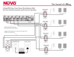
ENGLISH
IMPORTANT SAFETY INSTRUCTIONS
Danger
Exposure to extremely high noise levels may cause a permanent
hearing loss. Individuals vary considerably to noise induced hearing
loss but nearly everyone will lose some hearing if exposed to sufficiently
intense noise for a sufficient time. The U.S. Government's
Occupational Safety and Health Administration (OSHA) has specified
the following permissible noise level exposures:
DURATION PER DAY (HOURS) 8 6 4 3 2 1
SOUND LEVEL (dB)
90 93 95 97 100 103
According to OSHA, any exposure in the above permissible limits could
result in some hearing loss. Ear plugs or protectors in the ear canal or over
the ears must be worn when operating this amplification system in order to
prevent a permanent hearing loss. If exposure in excess of the limits as
put forth above, to insure against potentially harmful exposure to high
sound pressure levels, it is recommended that all persons exposed to
equipment capable of inducing high sound pressure levels, such as this
amplification system, be protected by hearing protectors while this unit is in
operation.
1.
2.
3.
4.
5.
6.
7.
8.
9.
10.
CAUTION
RISK OF ELECTRIC SHOCK
DO NOT OPEN
CAUTION: TO REDUCE THE RISK OF ELECTRIC SHOCK, DO
NOT REMOVE CHASSIS. NO USER-SERVICEABLE
PARTS INSIDE. REFER SERVICING TO QUALIFIED
SERVICE PERSONNEL.
11 .
12.
AVIS: RISQUE DE CHOC ELECTRIQUE-NE PAS OUVRIR.
13.
THIS SYMBOL IS INTENDED TO ALERT THE USER TO THE PRESENCE
OF NON-INSULATED "DANGEROUS VOLTAGE" WITHIN THE
PRODUCT'S ENCLOSURE THAT MAY BE OF SUFFICIENT MAGNITUDE
TO CONSTITUTE A RISK OF ELECTRIC SHOCK TO PERSONS.
14.
15.
THIS SYMBOL IS INTENDED TO ALERT THE USER TO THE PRESENCE
OF IMPORTANT OPERATING AND MAINTENANCE (SERVICING)
INSTRUCTIONS IN THE LITERATURE ACCOMPANYING THE UNIT.
APPARATUS SHALL NOT BE EXPOSED TO DRIPPING OR SPLASHING
16.
AND THAT NO OBJECTS FILLED WITH LIQUIDS, SUCH AS VASES,
SHALL BE PLACED ON THE APPARATUS.
Page 1
Read all safety and operating instructions before using this
product.
All safety and operating instructions should be kept for future
reference.
Read and understand all warnings listed on the operating
instructions.
Follow all operating instructions to operate this product.
This product should not be used near water, i.e. Bathtub,
sink,swimming pool, wet basement, etc.
Only use dry cloth to clean this product.
Do not block any ventilation openings, It should not be placed flat
against a wall or placed in a built-in enclosure that will impede the
flow of cooling air.
Do not install this product near any heat sources ;such
as,radiators, heat registers, stove or other apparatus (including
heat producing amplifiers) that produce heat.
Do not defeat the safety purpose of the polarized or groundingtype plug. A polarized plug has two blades with one wider than the
0ther.A grounding-type plug has two blades and a third grounding
prong. The wide blade or the third prong are provided for your
safety If the provided plug does not fit into your outlet, consult an
electrician for replacement of the obsolete outlet.
Protect the power cord being walked on or pinched, particularly at
Plugs, convenience receptacles and the point where they exit
from the apparatus. Do not break the ground pin of the power
supply cord.
Only use attachments specified by the manufacturer.
Use only with the cart, stand, tripod, bracket, or table specified by
the manufacturer or sold with the apparatus. When a cart is used,
use caution when moving cart/apparatus combination to avoid
injury from tip-over.
Unplug this apparatus during lightning storms or when unused for
long periods of time.
Care should be taken so that objects do not fall and liquids are
not spilled into the unit through the ventilation ports or any other
openings.
Refer all servicing to qualified service personnel. Servicing is
required when the apparatus has been damaged in any way;
such as, power-supply cord or plug is damaged, liquid has been
spilled or objects have fallen into the apparatus, the apparatus
has been exposed to rain or moisture, does not operate normally
or has been dropped.
WARNING: To reduce the risk of fire or electric shock, do not
expose this apparatus to rain or moisture.
ANTENNA
LEAD-IN
WIRE
GROUND
CLAMPS
ELECTRIC
SERVICE
ENTRANCE
NEC NATIONAL ELECTRICAL CODE
Page 3
ANTENNA
DISCHARGE UNIT
NEC SECTION
810-20
GROUNDING
CONDUCTORS
GROUND CLAMPS
POWER SERVICE
GROUPING ELECTRODE
SYSTEM NEC ART 250
PART H
NV-T2DF Wiring Diagram
DO NOT DISTURB
SYSTEM ON
2
3
4
5
6
7
8
9
1
SEEK
VOLUME
TUNE
CATEGORY
0
ENT
FM
AM
WX
XM
MENU
MENU
DND
MASTER
LOCK
DIM
HOTKEY
SOURCE
PLAY
AUX IN
USE ONLY NuVo
NV-T2PAS
POWERED ANTENNA SYSTEM
AUX IN
OUT
OUT
L
TRIGGER
ON=+12V
L
TRIGGER
ON=+12V
IR PASS-THRU
R
AUDIO
OUTPUT
R
AUDIO
OUTPUT
IR INPUT
Model NV-T2DF
Dual XM Tuner
NuVo Techonlogies LLC• Cincinnati Ohio USA
www.nuvotechnologies.com
NuVoNet
IN
+10
PRESET/DIRECT
SCAN
MUTE
POWER
OUT
RS 232
USB
TE RTEK
NT
I
IN
ER TEK
CM
IN
ANTENNA INPUT
VARIABLE
OUTPUT
TIP=L
RING=R
TUNER B
VARIABLE
OUTPUT
SPEAKER
40W/6 OHMS X 2
LEFT
RIGHT
TIP=L
RING=R
FIXED
OUTPUT
2
ZONE 2
3
L
4
3
SYSTEM
VARIABLE
OUTPUT
SPEAKER
40W/6 OHMS X 2
LEFT
RIGHT
TIP=L
RING=R
FIXED
OUTPUT
VARIABLE
OUTPUT
SPEAKER
40W/6 OHMS X 2
LEFT
RIGHT
3033118
VARIABLE
OUTPUT
SPEAKER
40W/6 OHMS X 2
LEFT
RIGHT
TIP=L
RING=R
FIXED
OUTPUT
ZONE 3
L
R
2
TIP=L
RING=R
TIP=L
RING=R
FIXED
OUTPUT
VAR.
OUT
SPEAKER
40W/6 OHMS X 2
LEFT
RIGHT
RS 232
FIXED
OUTPUT
FIX.
OUT
ZONE 6
ZONE 8
PROGRAM
CONNECT TO
NV-I8X
CONNECT TO
NV-I8EZP1
CONNECT TO
NV-I8X
USE NV-SLC1
CABLE
USE NV-NC1
CABLE
USE NV-SLC1
CABLE
NETWORK
DIGITAL LINK
ZONE 4
1
6
5
L
R
1
VARIABLE
OUTPUT
SPEAKER
40W/6 OHMS X 2
LEFT
RIGHT
FIXED
OUTPUT
ZONE 1
1
TUNER A
2
3
ZONE 5
1
2
3
4
1
2
ZONE 7
3
SUM1
USE CNLY WITH 250V FUSE
SYS ON
MODEL NV-I8M
SIX SOURCE EIGHT ZONE
AUDIO DISTRIBUTION SYSTEM
120V
60Hz 500W
FUSE:T5 A
NuVo Technologies Cincinnati Ohio USA
www.nuvotechnologies.com
R
4
SOURCE INPUTS
5
4
6
5
6
5
6
7
8
4
5
6
SUM2
EXT. MUTE
R
SOURCE STATUS
ZONE TRIGGER OUTPUTS
Diagram is shown with the NuVo Concerto System and NuVoNet.
Page 4
EMITTER OUTPUTS
SYSTEM
CONFORMS TO
UL STD.6500
CERTIFIED TO
CAN/CSA STD.E60065
US
C
SOURCE LINK
3033118
Tuner A
STANDBY
SELECT
3
4
5
MENU
PUSH TO
ENTER
6
7
PRE/DIR
14
SOURCE ON-OFF
15
Tuner B
AM 550
PRESET/DIRECT
1
2
3
4
5
6
7
8
9
0
SELECT
---–--––––
FM STEREO•AM•WEATHER
8
DISPLAY
MEMORY
MENU
PUSH TO
ENTER
PRE/DIR
SOURCE ON-OFF
PRESET/DIRECT
CATEGORY
<
2
MEMORY
CATEGORY
FM STEREO•AM•WEATHER
1
DISPLAY
13
<
FM 94.1 Stereo
Classic Rock
REMOTE
SENSOR
---–--––––
12
<
Model NV-T2DF
Dual FM/AM/WX Tuner
11
1
2
3
4
5
<
10
6
7
8
9
0
9
Front Panel
1. Stand-by LED: This LED (Light Emitting Diode) indicates that the T2 is plugged into an AC power source.
2. Remote Sensor: This IR (Infrared) receiver allows wireless remote control of the T2 functions. This IR input is active, even
when it is used in conjunction with the direct IR input on the back panel.
3. Frequency and Band Display: The display indicates the band AM, FM, or WX (Weatherband)and station frequency.
4. Preset/ RDS Display: This is a display of customized preset information, or RDS (Radio Data Service) information
transmitted with the station's broadcast. NuVoNet allows this to scroll automatically on the Concerto Display Pads (pg. 17 ).
5. Stereo: This indicates whether the signal reception is stereo. No display indicates mono. The T2 software allows a station
preset to be set in mono mode (pg. 21).
6. Signal Strength: This indicates the level of signal being received at the tuned frequency.
7. Select Knob: Turning the knob scrolls through the T2 menu options; pressing the knob selects the displayed menu option.
When not in menu mode, the Select knob tunes up and down. Pushing the knob selects the station.
8. Category Up and Down: This function requires the use of the T2 installation software. Categories allow station selection to
be set up according to specific listening genres.
9. Numeric Buttons: These buttons are programmable for direct station preset access. Customized alphanumeric strings can
be defined in the setup software (pg. 21). They can also be used for direct frequency tuning. These custom strings are
displayed on the Display Pads of an integrated Concerto system whenever a preset is accessed.
10. Display Button: This button toggles between RDS information on and off.
11. Memory Button: The memory button provides you with a personal “notepad” to store and recall artist and song information
originating from RDS data for future reference.
12. Menu: This button enters and exits the menu mode (pg. 11).
13. Pre/Dir: This toggles between numeric preset selection and direct station input.
14. Source: This button toggles between the available modes, AM, FM, WX (Weather Band), and Aux input if it has been
enabled through the advanced menu.
15. On/Off: Turns each individual tuner on and off.
Page 5
AUX IN
USE ONLY NuVo
NV-T2PAS
POWERED ANTENNA SYSTEM
OUT
AUX IN
TRIGGER
ON=+12V
L
Model NV-T2FX
FM/AM/WX-XM Tuner
NuVo Techonlogies LLC• Cincinnati Ohio USA
www.nuvotechnologies.com
OUT
TRIGGER
ON=+12V
L
IR PASS-THRU
NuVoNet
IN
OUT
USB
AUDIO
OUTPUT
R
IR INPUT
IN
TE RTEK
NT
I
AUDIO
OUTPUT
R
MADE IN CHINA
RS 232
ER TEK
CM
IN
ANTENNA INPUT
1
TUNER B
2
3
4
TUNER A
5
90~264V
SYSTEM
6
7
8
9
50~60Hz 15W
3033118
10
11
12
Back Panel
1. Antenna Input: Coax “F” connector brings in the signal input from the NuVo NV-T2PAS antenna (pg. 10).
2. Aux. Input: This stereo RCA connector is enabled through the advanced menu options (pg. 14), and allows an additional
audio source to be connected and accessed through the tuner source selection.
3. Audio Output: A Stereo RCA output allows the tuner audio signal to be connected to an amplifier source, such as the NuVo
Simplese, Essentia, and Concerto audio distribution systems.
4. Trigger ON: The voltage output provides a constant 12 volts when the Tuner is turned on.
5. Audio Output: This is a second stereo output designed to work with a tip, ring, sleeve 3.5mm stereo connection.
6. IR Pass-Thru: This 3.5mm connection is used to link IR control between two or more components used in the same
installation.
7. IR Input: The single IR Input accepts a mono 3.5mm patch cable for receiving IR information from an external IR receiver
without the use of an external IR emitter.
8. NuVoNet In: This RJ45 connection is used with one of the Peripheral Device inputs on the Concerto EZ Port (see pg. 17) to
enable direct one-to-one communication with the Concerto Display Pads.
9. NuVoNet Out: This RJ45 jack is used to link the NuVoNet communication between multiple NuVo Peripheral Devices such as
the T2 Tuners in a single installation.
10. USB: The USB port is used for downloading a configuration from your computer (see pg. 17).
11. RS232: This 9-pin DB9 connection allows serial communication with an external RS232 system. This may also be used for
downloading a configuration from your computer.
12. AC Power: This connects the T2 with an AC power source. When plugged into a live AC outlet the blue power LED (Light
Emitting Diode) on the T2's front panel will remain lighted. When neither tuner is on, the T2 is in standby mode and draws
less than 2 watts of power.
Page 6
8
1
PWR
A/B
TUNER
9
HOLD
ALL OFF
2
3
ENTER
4
SEEK
5
TUNE
6
CATEGORY
SCAN
7
10
1
2
3
4
5
6
7
8
9
PRE
0
ENT
DIR
FM
AM
WX
AUX
11
12
13
T2 Tuner
REMOTE CONTROL
NV-T2RC3 Remote Control
1. Power: The power button turns the selected tuner on and off.
2. Scroll Buttons: These buttons are the equivalent of turning the front panel Select knob. The top button is the equivalent of
turning the knob clockwise, and the bottom button is the equivalent of counterclockwise.
3. Enter: This button is the equivalent of pushing the Select knob on the front panel (see Front Panel #7).
4. Seek Up and Down: The seek buttons will tune to the next available station with the required signal strength. The signal
threshold can be adjusted higher or lower using the T2 Configurator software (see pg. 22), or through the advanced menu
options on the front panel (see pg. 12).
5. Tune Up and Down: The tune function steps through each station frequency regardless of the frequency signal strength.
6. Category Up and Down: The category buttons step through each of the defined genre categories. Categories must be defined
in the advanced settings of the T2 Configurator software (see pg. 24).
7. Pre/Dir: The T2 allows up to 10 preset stations in each of up to 10 preset banks. This button scrolls through each of the
defined banks and then to direct tuning. In direct tuning, you can use the numeric buttons to access a specific station
frequency. Presets are selected by a single push of numeric button 0-9.
8. Tuner A & B LED: This LED glows red when Tuner A is selected and green when Tuner B is selected. This LED glows only
momentarily when a button is pushed.
9. Tuner Selector: This button toggles between Tuner A and Tuner B operation.
10. Scan: The scan button tunes up to the next station with a signal strength above the programmed threshold and waits 5
seconds before automatically tuning to the next station. This uses the same signal level as the seek function.
11. Numeric Buttons: These buttons (0-9) are used to access a specific station frequency or choose a pre-defined station
preset.
12. Source Buttons: These four buttons select each of the four available audio sources within the T2.
Page 7
I. Installing the NV-T2DF Dual Tuner
Fig . 1
Stereo Audio Connections
AUX IN
AUX IN
OUT
USE ONLY NuVo
NV-T2PAS
POWERED ANTENNA SYSTEM
Each tuner has two audio output jacks. One is a stereo RCA
connection, and the other is a stereo 3.5mm mini. The RCA
output is an individual left and right channel connection made
with a standard RCA cable. The other end is connected to the
corresponding audio input on the back panel of the audio
amplifier. An example of this is one of the source inputs on the
back panel of a NuV0 audio distribution system, fig. 1.
L
R
L
AUDIO
OUTPUT
R
TRIGGER
ON=+12V
AUDIO
OUTPUT
IN
ANTENNA INPUT
VARIABLE
OUTPUT
TUNER B
VARIABLE
OUTPUT
SPEAKER
40W/6 OHMS X 2
LEFT
RIGHT
TIP=L
RING=R
TIP=L
RING=R
FIXED
OUTPUT
ZONE 1
1
TUNER A
VARIABLE
OUTPUT
SPEAKER
40W/6 OHMS X 2
LEFT
RIGHT
ZONE 2
2
3
4
TIP=L
RING=R
FIXED
OUTPUT
ZONE 3
ZONE 4
1
6
5
VARIABLE
OUTPUT
SPEAKER
40W/6 OHMS X 2
LEFT
RIGHT
TIP=L
RING=R
FIXED
OUTPUT
FIXED
OUTPUT
2
3
5
6
CONNECT TO
NV-I8X
L
L
R
1
L
R
2
USE NV-SLC1
CABLE
R
3
4
4
6
5
SOURCE STATUS
SOURCE LINK
SOURCE INPUTS
The 3.5mm stereo output labeled “AUDIO OUTPUT” is also
available for system connection. Compatible cables are
available with the male mini connection on each end, or with a
stereo RCA connection on one end, fig. 2.
OUT
TRIGGER
ON=+12V
Fig. 2
AUX IN
USE ONLY NuVo
NV-T2PAS
POWERED ANTENNA SYSTEM
AUX IN
OUT
OUT
L
TRIGGER
ON=+12V
L
R
AUDIO
OUTPUT
R
TRIGGER
ON=+12V
AUDIO
OUTPUT
IN
ANTENNA INPUT
VARIABLE
OUTPUT
TIP=L
RING=R
TUNER B
VARIABLE
OUTPUT
SPEAKER
40W/6 OHMS X 2
LEFT
RIGHT
TIP=L
RING=R
FIXED
OUTPUT
VARIABLE
OUTPUT
SPEAKER
40W/6 OHMS X 2
LEFT
RIGHT
TIP=L
RING=R
ZONE 2
2
3
4
TIP=L
RING=R
FIXED
OUTPUT
ZONE 3
ZONE 4
1
6
5
VARIABLE
OUTPUT
SPEAKER
40W/6 OHMS X 2
LEFT
RIGHT
FIXED
OUTPUT
FIXED
OUTPUT
ZONE 1
1
TUNER A
2
3
5
6
CONNECT TO
NV-I8X
L
L
R
1
L
R
2
3
USE NV-SLC1
CABLE
R
4
4
6
5
SOURCE STATUS
SOURCE LINK
SOURCE INPUTS
Direct IR Control
Fig. 3
Page 8
Model NV-T2DF
Dual XM Tuner
NuVo Techonlogies LLC• Cincinnati Ohio USA
www.nuvotechnologies.com
NuVoNet
IR PASS-THRU
IN
OUT
RS 232
USB
IR INPUT
IN
TE RTEK
NT
I
The T2 is designed for IR control via IR received by an audio
distribution system. In the NuVo Simplese or Essentia audio
distribution systems, the IR emitter outputs act as a repeater
to IR signals incident on the system keypads. The T2's wired IR
connector is a 3.5mm two-conductor (mono) jack labeled “IR
INPUT.” Using a mono mini-to-mini patch cable, connect the IR
emitter output of a Simplese or Essentia Main Unit to the IR
INPUT on the T2. The two tuners in the T2 respond to separate
IR codes, so the direct IR input replaces the need for external
IR emitters placed over the IR receiver windows on the front of
the unit, fig. 3. This connection is not used when using the
Concerto NuVoNet system. The NuVo Essentia and Simplese
systems are used for example, but the T2 is compatible with
any audio system that is capable of repeating IR.
ER TEK
CM
SYSTEM
VARIABLE
OUTPUT
SPEAKER
40W/6 OHMS X 2
LEFT
RIGHT
VARIABLE
OUTPUT
SPEAKER
40W/6 OHMS X 2
LEFT
RIGHT
TIP=L
RING=R
TIP=L
RING=R
FIXED
OUTPUT
5
2
6
3
7
VAR.
OUT
SPEAKER
40W/6 OHMS X 2
LEFT
RIGHT
RS 232
FIXED
OUTPUT
FIX.
OUT
ZONE 6
ZONE 5
1
3033118
4
8
1
4
2
5
ZONE 7
3
6
SUM1
SUM2
ZONE 8
PROGRAM
CONNECT TO
NV-I8EZP1
CONNECT TO
NV-I8X
USE NV-NC1
CABLE
USE NV-SLC1
CABLE
NETWORK
DIGITAL LINK
USE CNLY WITH 250V FUSE
SYS ON
MODEL NV-I8M
SIX SOURCE EIGHT ZONE
AUDIO DISTRIBUTION SYSTEM
120V
60Hz 500W
FUSE:T5 A
NuVo Technologies Cincinnati Ohio USA
www.nuvotechnologies.com
EXT. MUTE
EMITTER OUTPUTS
SYSTEM
CONFORMS TO
UL STD.6500
CERTIFIED TO
CAN/CSA STD.E60065
US
C
ZONE TRIGGER OUTPUTS
3033118
IR Pass-Thru
Fig . 4
The mini jack labeled “IR pass-thru" mini connection is
used for connecting forwarded IR signals to an audio
component connected to the auxiliary audio input.
Using the Aux. Input
Auxiliary
Audio Source
The T2 is equipped with an auxiliary audio input labeled
“AUX IN.” This will accept an audio signal from an external
component. This is most useful as an additional local
source, or an additional source in a multi-zone audio
system.
Audio
Out
AUX IN
L
R
OUT
TRIGGER
ON=+12V
L
AUDIO
OUTPUT
R
TRIGGER
ON=+12V
AUDIO
OUTPUT
IN
ANTENNA INPUT
TUNER B
TUNER A
Fig . 5
PWR
A/B
TUNER
HOLD
ALL OFF
Once the auxiliary input is enabled, it is selected from the
remote using the “AUX” button, fig. 5, or by pressing the
“Source” button for either Tuner A or Tuner B on the face
of the T2 and stepping through FM, AM, and WX (Weather
Band) to Aux., fig. 6.
ENTER
SEEK
TUNE
CATEGORY
SCAN
1
2
3
4
5
6
7
8
9
PRE
0
ENT
DIR
FM
AM
WX
AUX
T2 Tuner
REMOTE CONTROL
Fig . 6
Model NV-T2DF
Dual FM/AM/WX Tuner
STANDBY
REMOTE
SENSOR
Tuner A
DISPLAY MEMORY
MENU
PUSH TO
ENTER
PRE/DIR
SOURCE ON-OFF
PRESET/DIRECT
CATEGORY
<
FM STEREO•AM•WEATHER
Page 9
SELECT
Aux Input
1
2
3
4
5
<
The auxiliary input is a stereo RCA connection and
requires a standard RCA cable for the connection, fig. 4.
This must be enabled through the advanced menu, which
is accessed through the “Select Knob” on the face of the
T2 (see Menu Controls, AUX Input pg. 14) or in the T2
Configurator software (see Using the T2 Configurator
Software pg. 22). An additional advanced feature is the
ability to set the gain of the auxiliary signal to match the
output signal level of the T2.
AUX IN
OUT
USE ONLY NuVo
NV-T2PAS
POWERED ANTENNA SYSTEM
6
7
8
9
0
Antenna Input
Fig . 7
The T2 ships with a proprietary amplified AM/FM antenna. This
antenna is designed to work only with the NuVo T2 series
tuners. It can be located up to 200 feet from the tuner location,
and we recommend 75-ohm RG 6 coaxial cable with a standard
F style connector on each end. Simply attach the cable to the
connector at the bottom of the antenna, and into the “Antenna
Input” on the T2, fig. 7. Once connected, the T2 should
immediately receive broadcast signals and RDS (Radio Data
Service) when it is available.
We recommend placing the antenna inside in an attic or as
high as possible for the best possible AM and FM reception,
fig. 8. A 2 meter (6 foot) pre-terminated coaxial cable is
provided with the tuner package for testing the antenna
connection or if you choose to place the antenna close to the
tuner location.
AUX IN
USE ONLY NuVo
NV-T2PAS
POWERED ANTENNA SYSTEM
AUX IN
OUT
L
R
OUT
TRIGGER
ON=+12V
L
AUDIO
OUTPUT
R
TRIGGER
ON=+12V
AUDIO
OUTPUT
IN
ANTENNA INPUT
Fig . 8
USB and RS232 Communication
The T2 has two serial communication ports. These allow for
complete control of the T2 functions by RS232 control devices.
The necessary protocol for RS232 control is available through
the NuVo Website Prozone at
www.nuvotechnologies.com/prozone.
Page 10
TUNER B
TUNER A
Fig. 9: Menu Option Tree
(LOW to HIGH, 8 steps)
Operating Mode
Regional Setup
Fine Tuning
Seek Threshold
Audio Settings
Auto-ON
AUX Input
(previous menu)
Exit Menu: When you first enter the menu choices, the first
choice is to exit the menu, which takes you back to normal
turner operation.
Exit Menu
Force Mono
Brightness
Adv. Settings
Info
Brightness: This changes the intensity of each tuner's display.
The level choices range from 1- 8. The default level is the
brightest level 8, fig 10.
Menu
Force Mono: This is a useful feature when a stereo pair of
speakers is not available, or if the signal of a station is weak.
Forcing the signal to mono eliminates a weak station from
flipping in and out of stereo reception. If RDS display is OFF or
if there is no valid RDS data, the display will indicate “MONO.”
Version x.xx
Test Status (factory use only)
(previous menu)
Disabled
Enabled
Set AUX Gain
(previous menu)
Disabled
Enabled
(previous menu)
Bass
Treble
Balance
Output Level
(previous menu)
Disabled
Enabled
(previous menu)
FM Threshold
AM Threshold
Weather
(previous menu)
The T2 has many settings available in the menus. This allows
for many specialized set up options for basic tuner operation.
The menu is accessed from the front panel by pressing and
holding the “MENU” button. Once in menu mode, you can
scroll through the menu options by turning the “Select” knob
clockwise (CW) to move forward and counterclockwise (CCW)
to move backward. As the Select knob moves through the
menu, the choices appear on that tuner's display. The top line
contains the name of the current menu selection. The bottom
line shows the menu choices. When the desired menu option
appears on the display, pressing the Select knob enters the
menu choice. When the desired menu setting is made,
pressing the Select knob saves it (see menu option tree,
fig.9.) Pressing the MENU button once while you are in the
menu options moves you up one level. Pressing and holding
the MENU button exits the menu mode.
USA
Western Europe
Australia
New Zealand
Custom
(previous menu)
Concerto Src 1
Concerto Src 2
Concerto Src 3
Concerto Src 4
Concerto Src 5
Concerto Src 6
Stand-alone
(previous menu)
II. Front Panel Menu Controls
Info:
Version: This tells you what firmware version is
currently loaded on the T2.
Test Status: This is for factory diagnostic use only.
Fig. 10
Tuner A
SELECT
Brightness:
Low _____ High
FM STEREO•AM•WEATHER
Page 11
PUSH TO
ENTER
Advanced Settings
The following menu selections are not necessary for standard
tuner operation, but do provide a deeper level of control for
those who need it. When you scroll to “Advanced Settings” in
the menu, pressing the Select knob then accesses the
following menu options:
Operating Mode
Concerto Source 1-6: This must be set for the
appropriate NuVo Concerto source input, if the T2 is
going to be used with Concerto's NuVoNet control
network (see pg. 17 Using the T2 with Concerto and
NuVoNet).
Stand-alone: Stand-alone must be set when the T2 is
being used with any system other than the NuVo
Concerto audio distribution system.
Regional Setup
USA: This setting is optimized for the United States
and Canada.
European (Western): This setting is optimized for
Western Europe.
Australia: This setting is optimized for all of Australia.
New Zealand: This setting covers all of New Zealand.
These four settings cover most of the worldwide
tuning standards. For operation in countries outside
of these geographic regions, you may need to use the
advanced settings in the T2 Configurator software for
customizing the regional tuning standard (see pg. T2
Configuration Software, Advanced Settings).
Seek Threshold
This sets the effective station signal strength for seek and
scan tuning. With either of these modes, the tuner will
automatically tune up until it receives a good signal. You can
set the definition a good signal with the seek threshold
feature, fig. 11.
FM, AM, WX (Weather Band): All three available
bands are set the same way, but are adjusted
individually. Scroll with the Select knob to the
desired band and press the knob to select it. Once
selected, you can choose between five different
levels. High means the station needs to have a very
strong signal for the tuner to react. Low causes the
tuner to stop at any station with the slightest
measurable signal. The default is the middle setting.
This is an adjustment of the signal threshold. It sets
the minimum signal level necessary for tuning using
Seek or Scan.
Fig. 11
Fine-Tuning
The fine-tuning feature enables tuning with a smaller
frequency step to include more station frequency possibilities,
which may be used in areas allowing many low-power
broadcast stations.
FM: The standard tuning for North America and
Australia is .200 MHz steps, and the standard for
Europe and New Zealand is .100 MHz steps. Finetuning automatically drops the tuning steps to .05
MHz increments.
AM: The North America standard for AM tuning is in
10 kHz steps and Europe is 9 kHz. AM fine tuning goes
in 1 kHz steps.
Page 12
Tuner A
SELECT
Seek Threshold:
Low _____ High
FM STEREO•AM•WEATHER
PUSH TO
ENTER
Audio Settings
These selections are intended for some stand-alone
applications. They should be left at default settings for NuVo
audio systems. These systems allow identical audio control on
a per-zone basis.
Bass EQ: Bass output can be adjusted +12 dB or down
to 12 dB. The default setting is flat. This feature is
useful for stand-alone use with an amplifier that does
not have bass EQ control. If you are using the T2 with a
NuVo audio distribution system, or another system
that allows for EQ control, you should leave the T2 set
at 0 dB (flat), fig 12.
Treble EQ: Treble can be adjusted the same as bass.
The level ranges from 12 dB to +12 dB and defaults at 0
dB. As with the bass setting, this should not be used
unless there is no external EQ capability, fig. 13.
Balance: Left and Right channel output can be
adjusted if desired. As with the EQ adjustments, this
feature should not be used when the T2 is used with
an audio system that already has EQ and balance
adjustment capability, fig. 14.
Output Level: The signal level from the T2 can be
adjusted up or down to match the input gain
characteristics of other audio equipment in the
system. The default setting is 0 dB and the range is 6
dB to +12 dB, fig. 15.
Fig. 12
Tuner A
Bass EQ:
Bass EQ +4 dB
FM STEREO•AM•WEATHER
PUSH TO
ENTER
Fig. 13
Tuner A
SELECT
Treble EQ:
Treble EQ +6 dB
FM STEREO•AM•WEATHER
PUSH TO
ENTER
Fig. 14
Tuner A
Auto-ON
SELECT
Balance:
L------x------R
Enable/Disable: The T2 can be set to turn the tuner
displays on automatically when power is applied. This
is a good feature for stand-alone use. In the event of
a power outage or anytime AC power is lost and
restored, the T2 tuners will automatically turn back on
with the last-used settings without having to use the
ON/OFF button on the front panel.
This selection is not necessary when using the T2 with
the NuVo Concerto system, because the built-in power
management system between the T2 and Concerto will
automatically turn on the tuners when the Power
button is pressed on any of the Concerto's Display
Pads.
SELECT
FM STEREO•AM•WEATHER
PUSH TO
ENTER
Fig. 15
Tuner A
Output Level:
Output +3 dB
FM STEREO•AM•WEATHER
Page 13
SELECT
PUSH TO
ENTER
AUX Input
Disable/Enable: The T2 has an auxiliary audio input
that allows access through either of the tuners to an
additional audio source. To use this you must first
enable the input in the menu options.
AUX Gain: The audio input from an auxiliary source
can be adjusted to match the output of the T2's Tuner
A and Tuner B. AUX Gain is selected by using the Select
knob to scroll to that choice and press to enter. Once
AUX Gain is selected, amount of input up and down is
then controlled and set by using the Select knob to
adjust up or down, and then pressing the knob when
the desired gain setting has been reached, fig. 16.
Fig. 16
Noise Blanking
Disable/Enable: The T2 default setting is to have noise
blanking (partial to complete muting of weak noise
signals) Enabled. For areas of T2 operation having a
very low interference level, it may be desirable to
select this menu item and set Disabled in order to
listen to very distant, weak stations.
Page 14
Tuner A
SELECT
Aux Gain Set:
Output +5 dB
FM STEREO•AM•WEATHER
PUSH TO
ENTER
III. Stand-alone Front Panel Use of the T2
Tuning a Desired Station: Pressing the Select knob cycles
through the tuning modes.
Step Tune Mode: Each of the T2's tuners default to step tune
mode. When the Select knob is turned clockwise
(CW), the tuner will tune within the preset tuning
standard (see Advanced Menu Settings, Regional
Setup, pg. 12), and counter clockwise (CCW) to tune
down.
Fig. 17
STANDBY
Tuner A
DISPLAY
MEMORY
MENU
PUSH TO
ENTER
PRE/DIR
SOURCE ON-OFF
PRESET/DIRECT
CATEGORY
<
Scan Tune Mode: Scan tune works like Seek Tune, except the
tuner will only stay on a station for 5 seconds and then
continue to the next signal. To retain a selection, press
the Select knob before the tuner resumes scanning for
frequencies.
Tuning by Categories: A unique feature is the ability to
group station frequencies into specific genre
categories. The desired frequencies for each category
must be assigned in the T2 Configurator software (see
NV-T2DF Configurator software, Assigning
Categories). Once you have decided on the categories
you want to use and assigned specific station
frequencies, you will always have that template for
future use. To enter Category tuning, press the
“Category up or down keys.” This will scroll to the
next assigned category with each push. When a
category is selected, turning the Select knob will step
through all the frequencies within that category, fig.
17.
SELECT
104.7
Classic Rock
FM STEREO•AM•WEATHER
Seek Tune Mode: The seek tunes up when the Select knob is
turned CW and down when the Select knob is turned
CCW. In seek tune mode, the tuner will automatically
stop at the next available station signal. It will stay at
that selection until you tune to a new station.
Direct Numeric Tuning: The T2 allows for direct numeric entry.
To get to the Direct mode, press the PRE/DIR button
until “DIRECT TUNE” appears on the display. Then
pressing the numeric buttons in sequence for the
desired frequency and pressing the Select knob will
tune to that station.
REMOTE
SENSOR
1
2
3
4
5
<
Model NV-T2DF
Dual FM/AM/WX Tuner
6
7
8
9
0
Preset Tuning: The T2 is able to store 10 preset
stations in each of up to 10 banks of presets. This
allows a total of 100 presets. The factory default is
two banks of presets, but more banks can be added or
deleted in the T2 Configurator software. Saving a
preset is done simply by tuning to a desired station
and pressing and holding one of the numeric buttons
until the display reads “Preset Saved.” Once a preset
is saved, banks of presets are accessed by pressing
the PRE/DIR button, and then pressing the
appropriate number button accesses the desired
preset.
Radio Data Service (RDS) Information and Display Modes
The Radio Data Service is a format broadcasters can
use to send artist and song information with their
broadcast. Although this service is gaining in
popularity, all stations do not yet use it. If a station
is broadcasting RDS, the T2 will automatically scroll
what is being received. The Program Status Name
(PSN) data field (up to 8 characters) will appear in
the upper right of the display. This was intended by
RDS system architects to display a station name,
such as a call sign. The Radiotext field (up to 64
characters) will be displayed on the second line and
will scroll if it exceeds 16 characters. The Radiotext
message will be displayed on Display Pads in an
integrated Nuvo Concerto system. Radiotext was
intended for display of artist and title information.
Page 15
Signal Strength/Stereo Indicator
The signal strength indicator responds to the field
strength of the received carrier signal, fig. 18. This
indicator has seven discrete levels, with a single point
at the bottom of the character space indicating a
signal just detectable by the tuner, and a very strong
signal indicated by four lines of increasing length
above 3 dots. Stereo indication is also provided when
the tuner is successfully decoding FM Multiplex
stereo stations. The field will be blank if stereo
reception is not possible due to weak signal
conditions or if the station is broadcasting in
monaural (mono). The field will display MONO if
Force Mono is enabled from the MENU. This indicator
and Stereo lock information will be displayed upon
tuning to a new station. If RDS Receive is ON (see
previous section), then the indicator and Stereo lock
information will be displayed momentarily until valid
RDS PSN data has been received; then it will be
replaced by that data.
Source Switching
Pushing the “Source” button scrolls between AM, FM,
WX (Weather Band), and Auxiliary (Aux.) modes. The
auxiliary mode is optional and must be turned on
through the T2 Configuration software (see NV-T2DF
Configuration software, advanced settings, pg. ) or
through the advanced settings menu accessed at the
front panel (see Front Panel Menu Controls).
Fig. 18
Tuner A
102.7 Stereo
WXYZ
SELECT
---––-–
-––
FM STEREO•AM•WEATHER
PUSH TO
ENTER
Fig. 19
Page 16
Model NV-T2DF
Dual FM/AM/WX Tuner
STANDBY
REMOTE
SENSOR
Tuner A
SELECT
102.7 Rockin
Display Saved
FM STEREO•AM•WEATHER
DISPLAY
MEMORY
MENU
PUSH TO
ENTER
PRE/DIR
SOURCE ON-OFF
PRESET/DIRECT
CATEGORY
<
Using the Memory Feature
Memory is used to store a specific display for future
reference. This is useful for referencing specific RDS
information later. It can be used for viewing a song
title and artist that you might need to recall at a later
date. By pressing the “Memory” button with a single
tap, whatever information is scrolling on the display
at that time will automatically be saved in the first
memory position.
Pressing and holding the Memory button puts the T2
in memory recall mode. Turning the Select knob will
scroll up through the saved displays, starting with the
most recently saved. The T2 has the ability to save up
to 10 displays. When a new display is saved, it will
automatically place that information in the first slot,
and bump all previously saved displays down one.
Display number 10 will automatically drop off the list,
fig. 19.
1
2
3
4
5
<
Actual use of these data fields is not regulated, and
they may vary significantly in content between
stations. If you choose not to have RDS information
displayed, pressing the “Display” button will then
indicate “RDS receive OFF”. In this state, Stereo
indication and a signal strength indicator will replace
the PSN field on the top line, and only the station
frequency will be displayed on a connected zone's
Display Pad. Pressing the button again will restore
RDS and display “RDS receive ON.” Each press of the
“Display” button toggles between on and off.
6
7
8
9
0
IV. Using the T2 with the Concerto NuVoNet
Fig. 20
Setting Up the Tuner for NuVoNet
The T2 must be set for one of the Concerto source
inputs 1-6. This can be done at the front panel when
the tuner is first turned on, in the T2 Configurator
software, or through the front panel advanced menu.
The best way to utilize the T2 with NuVoNet is to set
up the T2 options in the included Configurator
software, and then download the configuration
through the rear-panel USB port, using the supplied
USB cable, fig. 20.
NuVoNet
IN
OUT
Model NV-T2DF
Dual XM Tuner
NuVo Techonlogies LLC• Cincinnati Ohio USA
www.nuvotechnologies.com
RS 232
USB
IR INPUT
TE RTEK
NT
I
IN
ER TEK
CM
SYSTEM
3033118
Fig. 21
When this is done, open the applicable configuration
from your configuration files or retrieve the
configuration from the Concerto main unit. Once the
appropriate configuration is opened, go to the Source
tab and place the T2 IR library in the appropriate
source locations 1-6. Once you have added the T2 as
two of the Concerto sources, you can then download
the configuration to the Concerto through the USB
port or the RS232 port on the back of the Concerto,
fig, 21. When the download is complete, your system
is ready for NuVoNet Communication.
Making the Connection
Prior to connecting to NuVoNet, the Concerto must
have the correct Configuration version downloaded
with the T2 representing two of the audio sources.
Making the NuVoNet connection is done simply by
connecting the “NuVoNet” output on the T2 to one of
the “Peripheral Device” inputs on the Concerto EZ
Port, fig., 22. This connection will then enable bidirectional NuVoNet communication with the Display
Page 17
Pads.
Fig. 22
DO NOT DISTURB
SYSTEM ON
1
2
3
SEEK
VOLUME
4
5
6
TUNE
7
8
9
CATEGORY
0
ENT
FM
AM
WX
XM
MENU
NU
ME
DND
MASTER
LOCK
DIM
HOTKEY
SOURCE
PLAY
POWER
IR PASS-THRU
NuVoNet
IN
OUT
Model NV-T2DF
Dual XM Tuner
NuVo Techonlogies LLC• Cincinnati Ohio USA
www.nuvotechnologies.com
USB
IR INPUT
RS 232
IN
TE RTEK
NT
ER TEK
CM
SYSTEM
3033118
Network Cable
+10
PRESET/DIRECT
SCAN
MUTE
I
Making Sure Your Concerto Is Ready for NuVoNet Use
Your Concerto System must be updated with at least
software version 1.40 for proper NuVoNet
communication with the T2. To check what
Configurator version you currently have, open the
Concerto Configurator software on your computer by
double-clicking on the Configurator icon on the
desktop. You will see a splash screen appear before
the software opens. This lists the current software
version. If you do not have version 1.40 or later, go to
www.nuvotechnologies.com/prozone. There you can
log onto the Download page and download the latest
version.
IR PASS-THRU
Operating the T2 with the Concerto Display Pad
By following the previous steps you should now be
able to operate the T2 from any of the Concerto
Display Pads. The Concerto Display Pads have
secondary tuner functions silk-screened on the bezel
below the associated keys. They appear under the
appropriate function buttons, fig. 23
Step Tune: Basic step tuning is done by pressing the
left or right arrows labeled Tune.
Seek Tune: Seek tuning automatically seeks to the
next frequency that meets the set signal strength
threshold (see T2 Configuration Software, Advanced
Settings, Tuning Parameters pg. 22). This is done by
pressing the left and right arrows labeled Seek (see
fig. 23).
Fig. 23
Radio Data Service: The Display Pad will scroll
received Radiotext data if the tuned station is
broadcasting it and if signal strength is sufficient.
When a defined preset is selected, the name of that
preset will appear on the display momentarily. If
Radiotext RDS data is being broadcast, it will then
automatically begin scrolling. This takes a few
moments while the information buffers.
Page 18
2
3
4
5
6
7
8
9
+10
0
ENT
TUNE
CATEGORY
SOURCE
PLAY
PRESET/DIRECT
SCAN
MUTE
Tuning by Categories: The provided genre categories
are defined in the T2 Configuration software (see NVT2DF Configuration Software, Advanced Settings,
Categories, pg. 24). You can use the stop and pause
buttons, also labeled “Categories,” to scroll up or
down through the defined categories. Once you have
chosen a category, the Seek up and Seek down
buttons will automatically tune through any
frequency within that category selection. Again, the
categories and the frequencies within each category
must be first assigned within the T2 Configuration
software.
1
SEEK
VOLUME
POWER
Scan Tune: Scan tuning automatically tunes to the
next available station frequency that meets the signal
threshold (as described above in the Seek Tune
Mode). Scan tune allows the T2 to settle on a
frequency for 5 seconds and then automatically go to
the next frequency. To select the station, push the
“ENT” button before the T2 resumes station scanning.
Scan tuning is initiated by pressing the “PLAY”
button, also labeled “Scan” (see fig. 23).
DO NOT DISTURB
SYSTEM ON
FM
AM
WX
XM
MENU
MENU
DND
MASTER
LOCK
DIM
HOTKEY
Direct Numeric Entry Tuning: Accessing direct tuning
is done by pressing the +10 button (see fig. 23). This
toggles between banks of presets (the T2
Configurator software allows for 10 banks each with
10 presets) and direct tune. When Direct Tune
appears on the display, a frequency can be
numerically entered using the numeric keypad on the
Display Pad. When you are entering a frequency
number, it is not necessary to enter the decimal, i.e.
102.7. The entered numbers will appear on the
display. When the ENT button is pressed, the T2 will
tune to that station.
Source Switching (radio band, aux input): The bottom
row of buttons on the Concerto Display Pad are
assigned FM, AM, WX (Weather Band), and Aux.
Changing the T2 source is done simply by pressing
one of those four buttons, (see fig. 23).
T2 Configuration Software
Basic setup and operation of the T2 is easily done from the
front panel, the included T2RC3 remote, or the Concerto
Display Pad. The T2 package includes the T2 Configurator setup
software designed to quickly move you through the Tuners'
setup options in a methodical fashion, and allow access to the
more advanced setup features. Configurations are saved as
files in the software's “Config” folder. Once complete,
configurations can be used as templates for future
installations.
2.0 Config
The Config tab is for the initial setup, which determines basic
tuner operation.
1.0 Start
The start tab allows you to load an existing configuration, or
create a new one. You can also retrieve a configuration from
the T2 and edit it.
1.0 Start
2.1 NuVoNet Operating Mode: This drop down menu allows you
to select between “Stand-alone” or as a Concerto source 1- 6.
If you are using the T2 as NuVoNet source for Concerto, you
must select a unique, dedicated source input for each Tuner (A
or B) being configured.
2.1 NuVoNet Operating Mode
1.1 After you have opened a configuration, the next step is the
Config Tab.
1.1 New Config
Page 19
2.2 Regional Setup: Depending on your geographic location,
the tuner needs to be set for the proper tuning standard. The
choices are USA and Canada, Western Europe, Australia, and
New Zealand. Countries outside these geographic locations
need the advanced custom setting (see Advanced Settings: 4.1
Custom Regional Setup).
2.4 Auto-On: In the event of loss of power, or if the T2 is
unplugged, the tuners can be set with this check box to
automatically turn on when power is returned.
2.4 Auto-On
2.2 Regional Setup
3.0 Presets
2.3 Brightness: This sets the intensity of the displays for each
tuner. The factory default is the maximum level 8.
2.3 Brightness
3.1 Preset Information: This section provides a display name,
band and tuning frequency for each preset. As the
Preset information fields are populated, the same information
will automatically fill the highlighted fields to the left.
Each bank of presets will hold 10 presets, and up to 10 banks
can be assigned. Three buttons at the bottom of the tab
are designated to assigning preset banks.
3.1 Preset Information
Page 20
3.4 Erase Bank
3.2 Add Bank: If you want to add a bank of 10 presets, the “Add
Bank “ button will bring up a window that allows you to name
the bank and automatically add it to the T2's presets.
3.2 Add Bank
Advanced Settings
3.3 Rename Bank: This button allows you to give a bank of
presets a customized name.
3.3 Rename Bank
The T2 software contains several specialized settings for more
advanced setup. Clicking on view and selecting “Advanced”
will expand the tabs as discussed in the next section to allow
access to this functionality.
4.0 Advanced Config
The T2 software allows for more advanced settings that if
necessary allow you to tweak the tuner's operation.
4.0 Advanced Config
3.4 Erase Bank: All preset banks, with the exception of the first
bank, can be erased one bank at a time. You cannot erase the
first bank of ten presets.
Page 21
4.1 Custom Regional Setup: Some countries operate at a tuning
standard outside the four preset regions. The Custom setting
allows specific parameters. One determining factor for tuning
is the “Pre-emphasis”. The two choices for this a are 50µS
(microseconds) and 75µS. The custom setting also allows for
specific setting of the minimum and maximum tuning
capability and the individual tuning steps for FM and AM.
4.1 Custom Regional Setup
4.2 Tuning Parameters: This section determines how the T2
tunes up and down. Seek/Scan Levels for each band, FM, AM,
and Weatherband sets the signal strength parameter for
searching stations. The lowest level 0 causes the tuner to stop
at any frequency with a very low signal. Level 4 (High), stops
only when a very strong signal is detected. The factory default
is Level 2 (Medium), which searches for a moderate signal.
This setting changes the necessary signal threshold, which is
the minimum signal level required for the T2 to recognize it
and lock on to the frequency.
4.2 Tuning Parameters
4.3 Fine Tuning: When checked, Fine Tuning changes the
tuning standard for FM from the default tuning to .05 MHz
step tuning, and AM will tune by single kHz increments, rather
than the default 10 kHz for USA and Canada, and 9 kHz for
Europe. The smaller tuning steps allow access to all station
frequencies.
4.3 Fine Tuning
4.4 Audio: Output Level increases or decreases the level of
signal from the audio output of each tuner. This setting and
balance, treble, and bass are best left at the default settings
for use with an audio distribution system such as NuVo
systems, that have built-in equalization capability. You may
want to make adjustments when the T2 is being used as a
stand-alone component with an amplifier.
4.4 Audio Output Level
Page 22
4.5 AUX Input: The T2 has an additional input that allows an
external device to be controlled through the T2's IR pass
through. When this input is enabled, the level of the signal
input can be adjusted up or down to match the tuners' signal
output level.
4.5 AUX Input
5.2 Level: This slider changes the signal level of the station.
This is especially useful for stations, such as many Public
Broadcasting System affiliates, that broadcast an
uncompressed signal with lower volume level than other
stations. This makes it possible for all stations to have the
same volume level as the user accesses presets.
5.1 Level
5.0 Advanced Presets
6.0 Categories
The preset tab in the advanced settings has additional
features for specific preset setup.
A unique feature of the T2 is the ability to set up categories of
listening. These are genre selections that automatically tune
through stations within that genre. Typical categories are
sports, talk, rock, classical. The T2 software has 38 preloaded
categories available. These are easily turned off if you do not
intend to use them, or new categories can be added to best fit
the user's needs.
5.1 High Cut: High-Cut is rarely used, but it can be a useful
function for a weaker AM signal that tends have highfrequency hiss. This drop down menu allows you to select a
frequency cut-off for high-frequency reception. Any audio
above the chosen frequency will be filtered with a gentle rolloff response.
5.1 High Cut
6.1 Categories Tab: By highlighting categories within the
categories tab, you can then click on the On/Off button to turn
that category off. This prevents unused categories from being
displayed when scrolling through the category selections. If
you know you will not use a category, you can delete it all
together, or add a specific category that is not listed. Any of
the categories can be given a customized name by clicking on
the rename button.
Page 23
6.1 Categories Tab
6.3 AM Freqs
6.2 FM Freqs: This tab lists all the available frequencies within
the FM band. When highlighted, the Frequency Information on
the right side of the tab allows you to name and categorize
each desired frequency in up to four different categories. The
Category drop down menus will only display the categories
you have turned on.
6.2 FM Freqs
When the desired frequencies have been categorized, the
Category tab will update to show the Categories you have
turned on and whether or not each category is used.
7.0 Update System
7.1 Download Configuration: The final step in the setup is to
download the configuration to the T2 via either its Rs232
serial port, or the USB port. At download the system gives
three options: Download configuration to both tuners, or to
either Tuner A or Tuner B. When you select an option, a window
Will appear with a download progress bar.
7.1 Download Configuration
6.3 AM Freqs: This tab is identical in function to the FM Freqs
tab, but categorizes the AM frequencies.
Page 24
7.2 Successful Download: When the download is complete a
final window will appear indicating that all the information
has downloaded successfully. Actual download time will vary
based on your computer's processing capabilities.
7.2 Successful Download
NV-T2DF Specifications
FM Section
Tuning Range
IF Frequency
Usable Sensitivity, 30 dB S/N
Auto Scan Sensitivity
Image Rejection
Limiting Sensitivity
AM Section
87.5 to 108 MHz
10.7 MHz
14 dB ?V
Adjustable
50 dB Min.
10 dB ?V
Tuning Range
IF Frequency
Usable Sensitivity
Auto Scan Sensitivity
Image Rejection
522 to 1720 kHz
450 kHz
25 dB S/N
Adjustable
50 dB Min.
Audio Section
Physical Specifications
Unit Size Millimeters
Unit Size Inches
Foot Height
Shipping Size Millimeters
Shipping Size Inches
Unit Weight Kilograms
Unit Weight Pounds
Shipping Weight Kilograms
Shipping Weight Pounds
Output level/Impedance
44 x 430 x 270
1.75 x 17 x 10.625
11mm / .433 in.
110 x 520 x 345
4.33 x 20.48 x 4.33
3.4
7.5
4.5
10
Adjustable/560 ohms
General
Input Voltage
Power Consumption, operating
Power Consumption, standby
Memory Backup
90-264V/ 50/60 Hz
10W Max
3W Max.
Indefinite
Infrared Section
Input Voltage
Input Carrier Frequency
Polarity
Page 25
3 - 15 V
38 kHz nominal
Active High