1
®
Professional Disc Jockey Products
PRO TT-1
PROFESSIONAL DIRECT DRIVE TURNTABLE
OWNER’S MANUAL
INDUSTRIES
11 Helmsman Avenue, North Kingstown, RI 02852
©1999
http://www.numark.com
PRO TT-1
Safety Information and Product Registration
7. Power Sources - This product should be
connected to a power supply only of the type
described in these operating instructions, or as
marked on the unit.
CAUTION
RISK OF ELECTRIC SHOCK
DO NOT OPEN
CAUTION: TO REDUCE THE RISK OF ELECTRIC SHOCK DO NOT
REMOVE ANY COVER. NO USER- SERVICEABLE PARTS INSIDE.
REFER SERVICING TO QUALIFIED SERVICE PERSONNEL ONLY.
The lightning flash with arrowhead symbol within the
equilateral triangle is intended to alert the user to the presence
of un-insulated “dangerous voltage” within the product’s
enclosure that may be of sufficient magnitude to constitute
a risk of electric shock to persons.
The exclamation point within the equilateral triangle is intended
to alert the user to the presence of important operating and
maintenance (servicing) instructions in the literature
accompanying this appliance.
CAUTION
FOR USA & CANADIAN MODELS ONLY
TO PREVENT ELECTRIC SHOCK DO NOT USE THIS (POLARIZED)
PLUG WITH AN EXTENSION CORD, RECEPTACLE OR OTHER
OUTLET UNLESS THE BLADES CAN BE FULLY INSERTED TO
PREVENT BLADE EXPOSURE.
SAFETY INSTRUCTIONS
8. Power Cord Protection - Power supply
cords should be routed so that they are not likely
to be walked upon or pinched by items placed on
or against them. When removing the cord from a
power outlet be sure to remove it by holding the
plug attachment and not by pulling on the cord.
9. Object and Liquid Entry - Take care that
objects do not fall into and that liquids are not
spilled into the inside of the turntable.
10. Damage Requiring Service - This product
should be serviced only by qualified personnel.
If you have any questions about service please
contact
at the number(s) shown on
the back cover of this manual.
11. Grounding or Polarization - Precautions
should be taken so that the grounding or
polarization means built into the turntable is not
defeated.
12. Internal/External Voltage Selectors Internal or external voltage selector switches, if
any, should only be reset and re-equipped with a
proper plug for alternative voltage by a qualified
service technician. Do not attempt to alter this
yourself.
1. Read Instructions - All the safety and operating
instructions should be read before this product is connected
and used.
2. Retain Instructions - The safety and operating
instructions should be kept for future reference.
3. Heed Warnings - All warnings on this product and in these
operating instructions should be followed.
4. Follow Instructions - All operating and other instructions
should be followed.
5. Water and Moisture - This product should be kept away
from direct contact with liquids.
NOTE: This apparatus does not exceed the
Class A/Class B (whichever is applicable) limits
for radio noise emissions from digital apparatus as
set out in the radio interference regulations of the
Canadian Department of Communications.
WARNING: To reduce the risk of fire or electric
shock, do not expose this appliance to moisture.
Electrical equipment should NEVER be kept or
stored in damp environments.
6. H e a t - Avoid placing this product too close to any high heat
sources such as radiators.
Please record the serial number of your unit as shown on the back of the chassis as well as the name of the
dealer from whom you purchased the unit. Retain this information for your records. Please return the warranty
card enclosed to register your product with us.
MODEL: PRO TT-1
PURCHASED FROM:_________________________
SERIAL NUMBER:__________________ DATE OF PURCHASE:________________________
- The Leader in DJ Technology
©1999
Industries
2
http://www.numark.com
PRO TT-1
PRO TT-1 Professional Turntable
INDEX
Safety Information
Product Registration
Page 2
System Precautions
Page 4
Introduction
Page 5
Features and Assembly Instructions
Page 6
Operating Instructions
Routine Maintenance
Page 10
Specifications
Page 11
Warranty and Service
Page 12
Contents of this package
Please check outer packing material for
hidden parts
1. Main Unit
2. Turntable platter
3. Rubber mat
4. Slip mat
5. Dust cover
6. 45-rpm adaptor
7. Counterweight
8. Headshell
8. Operating instructions
9. Registration Card
1
1
1
1
1
1
1
1
1
1
- The Leader in DJ Technology
©1999
Industries
3
http://www.numark.com
PRO TT-1
IMPORTANT INFORMATION...
Please read this entire manual before
connecting the PRO TT-1 to your system.
For optimum performance:
GENERAL SYSTEM PRECAUTIONS
• Always make sure that AC power is OFF while
making any connections.
• Use appropriate cables throughout your system:
Quality shielded audio cables and terminated shielded
video cables, low-capacitance preferred. Speaker
cables must be 14-gauge minimum; 12- or 10-gauge is
better.
• Do not force the platter to stop moving
while the motor is engaged. Quality
slipmats should be used to hold records in
position. Forcing the motor to stop can
damage the motor assembly.
• Never use spray cleaners or oils on the slide
control. Residues cause excessive dirt build-up
and this will void your warranty. In normal use
slide controls can last for many years. If they
malfunction (usually because of a dirty or dusty
environment)
• Never attempt to make any adjustments or repairs
other than those described in this manual. Take the
PRO TT-1 to your dealer or to an authorized
Service Center.
• Do not place the unit in a location where it will be
exposed to direct sun light or near a heating
appliance.
• Do not place the unit in a location where there is high
humidity or a lot of dust.
• Cartridge may pick up slight sound pressure or
vibrations of the speakers coming along the floor or
through the air resulting in howling. Find a location
which is very stable and free of vibration.
• The legs have functions for adjusting the height of
the unit itself. Adjust the legs to stabilize the main
body horizontally.
• Be sure plugs and jacks are tightly mated. Loose
connections can cause hum, noise or intermittents that
could easily damage your speakers.
• Reliability will be enhanced through the use of
banana connectors on the speaker wires. Observe
correct speaker wire polarity. If in doubt, consult your
dealer or a qualified technician.
• Take care to connect only one cable at a time. Pay
attention to the color-coded, labelled Input and Output
jacks.
• ALWAYS remember: “TURN AMPS O N LAST
AND OFF FIRST”. Begin with master faders or
volume controls on minimum and the amplifier
gain/input control(s) down. Wait 8 to 10 seconds
before turning up the volume. This prevents
transients which may cause severe speaker damage.
• Use restraint when operating controls. Try to move
them slowly. Rapid adjustments could damage
speakers due to amplifier clipping.
• Avoid amplifier “clipping” at all costs: this
occurs when the red LEDs (usually on the front panel
of most professional power amplifiers) start flashing.
“Clipping” is when the power amplifier is distorting
and working beyond it’s limits. Amplifier distortion is
THE major cause of speaker failure.
• To prevent fire or shock hazard, do not expose the
unit to rain or moisture. Never place cans of beer,
soda, glasses of water or anything wet on top of
the turntable!
A NOTE ON CABLES:
Quality cable makes a big difference in
audio fidelity and punch. See your
dealer or an electronics or
audio specialist store if you are not
sure which cables to get.
- The Leader in DJ Technology
©1999
Industries
4
http://www.numark.com
PRO TT-1
CONGRATULATIONS!
You are now the owner a
PRO TT-1 Professional Turntable, the
ultimate tool for todays skilled turntablist. This unit has been designed by DJs for
DJs. With it’s super high-torque platter and large back lit display the
PRO TT-1 gives the professional absolute total control. Enjoy this turntable and
remember:
BE CREATIVE!
Thank you for buying Numark DJ products!
FEATURES:
•± 10% pitch adjustment
• High Torque Platter Motor
• Start/Stop Button
• High Torque Braking
• 33/45/78 RPM speeds
• Forward and Reverse Platter Direction
• Unique Top Plate LCD Display indicating:
• Play/Pause Mode
• Pitch Change Percentage
• Platter Speed
• Quartz Lock Mode
• Rotating 12 segment circular display indicating the
spinning actions of the platter at all times
• S Shaped Tone arm assembly with:
• Counterweight
• Height Adjustment
• Skating Adjustment
• Height Lock
• Lever lift with height adjustment
• Tone arm holder with locking mechanism
• Pop-up Stylus Target Light
• Quartz Lock of 0% speed position
• 45RPM adapter and holder
• Extra Stylus Holder
• Output for:
• Audio {Left Right & Ground}
• Platter Speed - to be used with external process devices
• External START/STOP control
• Adjustable Feet for Leveling
• Easily removable smoked plastic lid
- The Leader in DJ Technology
©1999
Industries
5
http://www.numark.com
PRO TT-1
FEATURES,OPERATING, & ASSEMBLY INSTRUCTIONS...
9
11
10
8
12
7
6
14
5
13
4
17
1
15
2
16
3
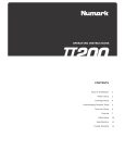
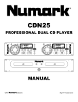
To fully appreciate the features of the
P R O T T - 1, please read this entire manual before you begin
operation. The PRO TT-1 should be placed on a level sturdy surface. Keep in mind that there are a few features you may
never have seen before on a turntable of this type that you will need to read about to use properly.
Start by removing all parts from the package and place on a
level surface. Carefully check all packing material for
hidden parts. Use the contents guide for reference.
Do not discard any packing materials!
1. Power Dial
On - Rotate Right
Off - Rotate Left
2. START/STOP - Pressing once engages high torque
motor pressing again engages brake.
3. Platter Revolution Speed Buttons
33rpm - Press 33
45rpm - Press 45
78rpm - Press 33 and 45
4. Strobe Light - This Pulses a beam of light at the Strobe
Dots (5). By doing so the large dots will seem not to move
in Quartz Lock mode.
5. Strobe Dots - Four rows of dots that indicate various
stages in pitch adjust.
-3.3% - outer row
0% - large dots
+3.3% - next row
+6% - inner row
6. Platter - Place this on the Center Spindle (7) and
carefully position with the Alignment Pins (17)
7. Center Spindle - Keeps platter and records centered.
Place the supplied slipmat on the Center Spindle now.
- The Leader in DJ Technology
©1999
Industries
6
http://www.numark.com
PRO TT-1
8. 45 Adapter - Place on Center Spindle (7) for playing 7”
records with large center holes.
9. Forward/Reverse Buttons - These determine the
direction the platter will spin.
14. Quartz Lock
On - will hold the revolution speed at exactly the
specified speed (3)
Off - will allow use of the Pitch Adjust (13)
15. LCD Display - Explained in Display Section
10. Lid Hinge Holder - Place the bottom tabs of your lid
hinges in here after you finish assembly.
16. Target Light - Press the button to the right and a light
will pop up directed at the stylus position.
11. Extra Stylus Holder - Place extra headshells here.
12. Tone Arm Assemble - Explained in tonearm section
17. Voltage Selector - with unit unplugged set the desired
voltage for your location using a screw driver.
115V
13. Pitch Adjust - use this the change the speed of the
platter when quartz lock is inactive. You can adjust the
revolutions by ±10%.
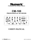
TONE ARM ASSEMBLY
30
29
28
230V
20. Headshell - Attach the cartridge here.
When installing a cartridge, refer to the installation
instructions supplied by the manufacturer of that cartridge.
During installation, attach the stylus protector to guard the
stylus tip from damage.
Attach wires as follows:
White (L+)Left channel+
Blue (L-)Left channel
Red (R+)Right channel+
Green (R-)Right channel
27
21. Headshell Locking Nut - Attach headshell by inserting
into the front end of the tonearm, then turn the locking
nut clockwise with the head shell firmly held horizontally.
25
24
26
23
22. S-Shaped Tone Arm
22
23. Tone Arm Clamp and Rest - Use this rest the tone arm
and clamp it in position during transportation.
24. Tone Arm Lift - This elevates the tone arm above the
record surface
21
20
25. Tone Arm Lift Adjust Screw - Controls the amount of lift
26. Tone Arm Lever - Controls the up and down action of
the Tone Arm Lift
- The Leader in DJ Technology
©1999
Industries
7
http://www.numark.com
PRO TT-1
27. Anti-Skate Control - This applies inward force to the
tonearm so it doesn’t skip outward across the record due to
the centrifugal force of the record spinning. Cartridge
manufacturers usually specify the proper setting of this.
(3) Release the arm clamp and lift the tonearm from the
arm rest so it moves freely.
(4) Rotate the counterweight until the tonearm is
approximately balanced horizontally (floats freely).
28. Tone Arm Height Adjust - This allows the tone arm to
be properly align with the platter surface.
29. Height Lock - Prevents accidental adjustment if the
height.
30. Counterweight - Adjustment creates the proper
downward pressure of the stylus to the record. Attach
now by sliding the counterweight onto the rear of the
tonearm. Twist it lightly and it will screw onto the rear shaft
of the tonearm.
(5) Refasten the tonearm with the arm clamp.
(6) Hold the counterweight stationary
with one hand and rotate only the
stylus-pressure ring to bring the
number "O" of the ring into alignment
with the center line on the tonearm
rear shaft.
Counterweight
Tonearm
(7) Rotate the counterweight with
scale ring clockwise to the correct
stylus pressure following the
manufacture's recommendation.
The following explains proper counterweight and
anti-skating set up. Cartridge manufacturers usually specify
the proper settings.
Note: Failure to follow recommended stylus pressure
can damage both the stylus and record. This can also
seriously degrade performance.
(1) Remove the stylus protector, do not touch the
stylus tip during the adjustment.
(8) Set the anti-skating control knob (27) to the same
value as the stylus pressure, unless your manufacturer
specifies otherwise.
(2) Set the cueing lever to the lower position so it does
not effect tone arm height.
LCD DISPLAY
34
33
35
31. Speed Indication
33 - 33 rpm
45 - 45 rpm
33 + 45 - 78 rpm
32. Speed Adjust Indication - This will display up to ± 10%
adjustment in speed.
33. Play/Pause - Indicates current state of the platter
34. Pitch/Quartz I indicates current mode of operation
31
32
35. Platter Wheel - simulates all actions of speed and
direction of the platter.
- The Leader in DJ Technology
©1999
Industries
8
http://www.numark.com
PRO TT-1
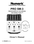
REAR PANEL DIAGRAM...
42
41
43
40
45
47
44
46
40. Removable Lid - Protects the turntable from dirt and
dust.
41. Hinge Assembly - Holds the lid and turntable together.
Attach now by sliding the bottom tabs of the Hinge
Assembly into the Hinge Holders (10).
42. Platter Speed Output - This output is to be used with
external devices the require platter speed information.
43. Remote Start/Stop - This is used with external control
devices.
Tech note: This circuit is a normally open, use a
momentary switch and a 1/4” mono plug to change
play states of the unit.
44. Adjustable Feet - Turn feet to level the platter surface.
45. Phono Output - Plug these into your mixer or
preamplifiers’ turntable input.
46. Ground Cable - Attach to the ground screw on your
mixer or preamplifier to prevent turntable hum.
47. Power Cord - Plug this into an appropriate power outlet
after checking your power setting switch (18) under the
platter.
Note: Please refer to CAUTION on page 2 concern
proper use of power
Your assembly should now be complete. Place your turntable on a
vibration free level surface and attach to your mixer or preamplifier. If you
are using the turntable for slip cueing or mixing music you will want to use
the slipmat and not the rubber mat.
- The Leader in DJ Technology
©1999
Industries
9
http://www.numark.com
PRO TT-1
GENERAL OPERATING INSTRUCTIONS...
1. Turn the power dial to turn on, the speed indicator and the strobe-illuminator will light up.
2. Turn on and raise the target light for illuminating the stylus tip by pushing the target light button.
3. Place a record on the turntable mat, when playing a 45rpm record with a large center hole, place the
45-rpm adaptor on the center spindle.
4. Set the rotation speed (33/45/78) to match the record.
5. Release the arm clamp.
6. Set the cueing lever to the up position.
7. Press the Start/Stop button, the turntable platter will start to rotate.
8. Move the tonearm over the desired groove.
9. Set the cueing lever to the down position, the tonearm will descend slowly onto the record and play
begins.
10. Adjust the pitch to a desirable speed. The pitch control is variable in a range of +/- 10%. During
play, observe the strobe dots, if the strobe dots appear to the right, the pitch is slower than the rated
speed, if flow to the left, the pitch is faster than the rated speed, if the strobe dots appear stationary,
which means the platter is in normal turntable speed. Move the pitch control slider up or down to
adjust the speed.
11. To suspend play, lift tone arm with cueing lever.
12. When play is finished,raise the cueing lever, move the tonearm to the arm rest, secure the tonearm
with the arm clamp.
13. Turn off the target light off by pushing the light back down.
14. Press the Start/Stop button to stop the platter rotating, turn the power dial to turn off the power.
Maintenance..
Routine maintenance should be performed by cleaning the stylus periodically with a soft brush to
prevent the accumulation of dust. When the sound becomes distorted or noisy, check the stylus. If
it is worn out, replace with a new one. From time to time, the dust cover and turntable cabinet should
be wiped with a soft, dry cloth. Use of any volatile materials as alcohol,thinner, benzine, etc.,may
remove the paint or damage the luster and should not be used.
- The Leader in DJ Technology
©1999
Industries
10
http://www.numark.com
PRO TT-1
SPECIFICATIONS...
TURNTABLE SECTION
Type
Driving method
Motor
Turntable platter
Turntable speed
Pitch Variance
Starting Torque
Braking
3-speed, full manual
Direct drive
12 Pole, 3 Phase, Brushless DC Motor
Aluminum diecast 330mm dia.
33-l/3 , 45, and 78 rpm
±10%
more than 2.2kgf.cm
Electronic
OUTPUT
Wow and flutter
S/N ratio
Output Difference
Output Level
Channel Separation
Pitch
0.13%
50dB (DIN-B)
2.3dB
1.7 - 3.5 mV
16dB
675±1Hz with 33 1/3 rpm
1170±1Hz with 78 rpm
TONEARM SECTION
Type
Effective length
Overhang
Tracking Force
Anti-Skate
Cartridge Weight
Static Balanced S-shaped with detachable headshell
234mm
20mm
0-4g
0-7g
6-10g
GENERAL
Power supply
AC110-127V / 220-240V, 50/60Hz
Power consumption
15 Watts
Dimension (W x D x H) 450 x 352 x 148.5 mm
17 3/4” x 13 3/4” x 5 7/8”
Weight
10.8Kgs 24 lbs
Specifications and design may be changed without notice due to continual product improvement.
- The Leader in DJ Technology
©1999
Industries
11
http://www.numark.com
®
LIMITED PRODUCT WARRANTY
1. What is covered and for how long? NUMARK INDUSTRIES LCC ("NUMARK") warrants to the original purchaser that NUMARK'S DJ mixers
and amplifiers are free from defects in material and workmanship under normal use and service for the period commencing upon the date of
purchase from an authorized NUMARK dealer and continuing for the following period of time after that date for (2) Years. The warranty is
extended to (3) Years with the completion of the warranty card provided that the warranty card is completed and returned within (30) days from
the date of purchase.
All other NUMARK products are warranteed for (1) Year including but not limited to CD players, turntables, preamplifiers, beatkeepers, equalizers,
microphones, headphones, and all other accesories.
2. What is not covered? This Limited Warranty is conditioned upon proper use of the product by the purchaser.
This Limited Warranty does not cover: (a) defects or damage resulting from accident, misuse, abuse, neglect, unusual physical or electrical stress,
modification of any part of the product, or cosmetic damage; (b) equipment that has the serial number removed or made illegible; (c) all plastic
surfaces and other externally exposed parts that are scratched or damaged due to normal use; (d) defects or damage from improper testing,
operation, maintenance, installation, adjustment, or service of the mixers; (e) crossfaders.
3. What are NUMARK'S obligations? During the applicable warranty period, NUMARK will repair or replace, at NUMARK'S sole discretion,
without charge to the purchaser, any defective component part of the mixer. To obtain service under this Limited Warranty, purchaser must first
contact NUMARK and obtain a return authorization number ("RA#"). Purchaser must then return the mixer to NUMARK in an adequate container
for shipping, accompanied by purchaser's sales receipt or comparable proof of sale showing the date of purchase, the serial number of the product,
and the seller's name and address. To obtain an RA# and assistance on where to return the mixer, contact NUMARK customer service at 401-2959000. Upon receipt, NUMARK will repair or replace the defective products. NUMARK may, at NUMARK'S sole discretion, use rebuilt,
reconditioned, or new parts or components when repairing any product or replace a product with a rebuilt, reconditioned or new product.
Repaired mixers will be warranted for a period equal to the remainder of the original Limited Warranty on the original mixer or for (90) days,
whichever is longer. All replaced parts, components, boards and equipment become the property of NUMARK. If NUMARK determines that any
mixer is not covered by this Limited Warranty, purchaser must pay all parts, shipping, and labor charges for the repair or return of such mixer.
4. What are the limits on NUMARK'S liabilities? THE WARRANTIES GIVEN IN THIS LIMITED WARRANTY, TOGETHER WITH ANY IMPLIED
WARRANTIES COVERING NUMARK MIXERS, INCLUDING WITHOUT LIMITATION ANY WARRANTIES OF MERCHANTABILITY OR FITNESS
FOR A PARTICULAR PURPOSE, ARE LIMITED TO THE DURATION OF THIS LIMITED WARRANTY. EXCEPT TO THE EXTENT PROHIBITED BY
APPLICABLE LAW, NUMARK SHALL NOT BE LIABLE FOR ANY SPECIAL, INCIDENTAL, CONSEQUENTIAL, INDIRECT OR SIMILAR
DAMAGES, LOSS OF PROFITS, DAMAGES TO PURCHASER'S PROPERTY, OR INJURY TO PURCHASER OR OTHERS ARISING OUT OF THE
USE, MISUSE OR INABILITY TO USE ANY NUMARK MIXER, BREACH OF WARRANTY, OR NEGLIGENCE, INCLUDING BUT NOT LIMITED TO
NUMARK'S OWN NEGLIGENCE, EVEN IF NUMARK OR ITS AGENT HAS BEEN ADVISED OF SUCH DAMAGES, OR FOR ANY CLAIM
BROUGHT AGAINST PURCHASER BY ANY OTHER PARTY. THIS LIMITED WARRANTY IS THE COMPLETE WARRANTY FOR NUMARK'S
MIXERS, AND IS GIVEN IN LIEU OF ALL OTHER EXPRESS WARRANTIES. THIS LIMITED WARRANTY SHALL NOT EXTEND TO ANYONE
OTHER THAN THE ORIGINAL PURCHASER OF THIS PRODUCT AND STATES PURCHASER'S EXCLUSIVE REMEDY. IF ANY PORTION OF THIS
LIMITED WARRANTY IS ILLEGAL OR UNENFORCEABLE BY REASON OF ANY LAW, SUCH PARTIAL ILLEGALITY OR UNENFORCEABILTY
SHALL NOT AFFECT THE ENFORCEABILITY OF THE REMAINDER OF THIS LIMITED WARRANTY WHICH PURCHASER ACKNOWLEDGES IS
AND WILL ALWAYS BE CONSTRUED TO BE LIMITED BY ITS TERMS OR AS LIMITED AS THE LAW PERMITS.
This Limited Warranty allocates risk of product failure between purchaser and NUMARK, and NUMARK'S product pricing reflects this allocation of
risk and the limitations of liability contained in this Limited Warranty. The agents, employees, distributors, and dealers of NUMARK are not
authorized to make modifications to this Limited Warranty, or make additional warranties binding on NUMARK. Accordingly, additional statements
such as dealer advertising or presentation, whether oral or written, do not constitute warranties by NUMARK and should not be relied upon.
5. How does state law apply to this warranty? SOME STATES DO NOT ALLOW THE EXCLUSION OR LIMITATIONS OF INCIDENTAL OR
CONSEQUENTIAL DAMAGES OR HOW LONG AN IMPLIED WARRANTY LASTS, SO THE ABOVE LIMITATIONS OR EXCLUSIONS MAY NOT
APPLY TO PURCHASER.
This Limited Warranty gives you specific legal rights. You may also have other rights, which vary from one jurisdiction to another.
RETURN INFORMATION
1. A Return Authorization number must be obtained from Numark through the address or phone numbers below.
2. A copy of the original sales receipt must also be included for the equipment to be repaired under warranty.
3. The faulty equipment must be packed in its original packaging.
4. One additional outer layer of packaging must be included to ensure product safety. Failure to do so may inadequately protect the
equipment in transit and, therefore, jeopardize the customer’s warranty.
5. Numark will not accept COD shipments and no call tags will be issued for merchandise return.
6. Numark will not return repaired merchandise to customers by priority service, unless by written request at the customer’s cost.
Requests must be submited in writing with merchandise returned.
7. The defective Numark equipment should be sent, FREIGHT PREPAID with Return Authorization number clearly printed on the outer
packaging and original sales receipt enclosed to:
INDUSTRIES
Attention: Service Department
11 Helmsman Avenue
North Kingstown, RI 02852 USA
Phone:
Fax:
E-mail:
+1 (401) 295-9000
+1 (401) 295-5200
[email protected]