1
®
Professional Disc Jockey Products
PRO SM-1
PROFESSIONAL SCRATCH MIXER
OWNER’S MANUAL
INDUSTRIES
11 Helmsman Avenue, North Kingstown, RI 02852
©1999
http://www.numark.com
PRO SM-1
7. Power Sources - This product should be
connected to a power supply only of the type
described in these operating instructions, or as
marked on the unit.
CAUTION
RISK OF ELECTRIC SHOCK
DO NOT OPEN
CAUTION: TO REDUCE THE RISK OF ELECTRIC SHOCK DO NOT
REMOVE ANY COVER. NO USER- SERVICEABLE PARTS INSIDE.
REFER SERVICING TO QUALIFIED SERVICE PERSONNEL ONLY.
The lightning flash with arrowhead symbol within the
equilateral triangle is intended to alert the user to the presence
of un-insulated “dangerous voltage” within the product’s
enclosure that may be of sufficient magnitude to constitute
a risk of electric shock to persons.
The exclamation point within the equilateral triangle is intended
to alert the user to the presence of important operating and
maintenance (servicing) instructions in the literature
accompanying this appliance.
CAUTION
FOR USA & CANADIAN MODELS ONLY
TO PREVENT ELECTRIC SHOCK DO NOT USE THIS (POLARIZED)
PLUG WITH AN EXTENSION CORD, RECEPTACLE OR OTHER
OUTLET UNLESS THE BLADES CAN BE FULLY INSERTED TO
PREVENT BLADE EXPOSURE.
SAFETY INSTRUCTIONS
8. Power Cord Protection - Power supply
cords should be routed so that they are not likely
to be walked upon or pinched by items placed on
or against them. When removing the cord from a
power outlet be sure to remove it by holding the
plug attachment and not by pulling on the cord.
9. Object and Liquid Entry - Take care that
objects do not fall and that liquids are not spilled
into the mixer.
10. Damage Requiring Service - This product
should be serviced only by qualified personnel.
If you have any questions about service please
contact
at the number(s) shown on
the back cover of this manual.
11. Grounding or Polarization - Precautions
should be taken so that the grounding or
polarization means built into the mixer are not
defeated.
12. Internal/External Voltage Selectors Internal or external voltage selector switches
should only be reset and re-equipped with a
proper plug for alternative voltage by a qualified
service technician. Do not attempt to alter this
yourself.
1. Read Instructions - All the safety and operating
instructions should be read before this product is
connected and used.
2. Retain Instructions - The safety and operating
instructions should be kept for future reference.
NOTE: This apparatus does not exceed the
Class A/Class B (whichever is applicable) limits
for radio noise emissions from digital apparatus as
set out in the radio interference regulations of the
Canadian Department of Communications.
3. Heed Warnings - All warnings on this product and in
these operating instructions should be followed.
4. Follow Instructions - All operating and other
instructions should be followed.
WARNING: To reduce the risk of fire or electric
shock, do not expose this appliance to rain or
moisture. Electrical equipment should NEVER be
kept or stored in damp environments.
5. Water and Moisture - This product should be kept
away from direct contact with liquids.
6. Heat - Avoid placing this product too close to any high
heat sources, (ie. radiators).
Please record the serial number of your unit as shown on the back of the chassis as well as the name of the
dealer from whom you purchased the unit. Retain this information for your records. Please return the warranty
card enclosed to register your mixer with us.
MODEL: PRO SM-1
SERIAL NUMBER:__________________
PURCHASED FROM:_________________________
DATE OF PURCHASE:________________________
- The Leader in DJ Technology
©1999
Industries
2
http://www.numark.com
PRO SM-1
PRO SM-1 Professional Scratch Mixer
INDEX
Safety Information
Product Registration
Page 2
Precautions
Page 4
Introduction
Page 5
Front Panel Diagram
Page 6
Operating Instructions
Page 7
Rear Panel Diagram
Page 9
Connection Diagram
Page 10
Specifications
Page 10
Block Diagram
Page 11
Warranty and Service
Page 12
- The Leader in DJ Technology
©1999
Industries
3
http://www.numark.com
PRO SM-1
IMPORTANT INFORMATION...
Please read this entire manual before connecting the PRO SM-1 to your system.
For optimum performance:
SYSTEM PRECAUTIONS
• Always make sure that AC power is OFF while
making any connections.
• Use appropriate cables throughout your system:
Quality shielded audio cables and terminated shielded
video cables, low-capacitance preferred. Speaker
cables must be at least 14-gauge; 12 or 10-gauge is
preferable.
• Do not use excessively long cables (i.e. over
50ft/14m). Be sure plugs and jacks are tightly mated.
Loose connections can cause hum, noise or
intermittents that could easily damage your speakers.
• Never use spray cleaners or oils on
the slide controls. Residues will
cause excessive dirt build-up and this
will void your warranty. In normal
use slide controls can last for many
years. If they malfunction (usually
because of a dirty or dusty
environment), consult a professional
technician.
• Never attempt to make any adjustments or repairs
other than those described in this manual. Take the
PRO SM-1 to your dealer or to an authorized
Service Center.
A NOTE ON CABLES:
Quality cable makes a big difference in audio
fidelity and punch. See your
dealer or an electronics or audio specialist
store if you are unsure which cables to use.
• Reliability will be enhanced through the use of
banana connectors on the speaker wires. Observe
correct speaker wire polarity. If in doubt, consult your
dealer or a qualified technician.
• Connect only one cable at a time, paying close
attention to the color-coded, labelled Input and Output
jacks.
• ALWAYS REMEMBER
“TURN AMPS O N LAST AND OFF FIRST”.
Begin with master faders or volume controls on
minimum and the amplifier gain/input control(s) down.
Wait 8 to 10 seconds before turning up the volume.
This prevents transients which may cause severe
speaker damage.
• Use restraint when operating controls by moving
them slowly. Rapid adjustments may damage
speakers due to amplifier clipping.
• Avoid amplifier “clipping” at all costs: this
occurs when the red LEDs (usually on the front panel
of most professional power amplifiers) start flashing.
“Clipping” is when the power amplifier is distorting
and working beyond it’s limits. Amplifier distortion is
the major cause of speaker failure.
• To prevent fire or shock hazard, do not expose the
unit to rain or moisture. Never place any beverage
or anything wet on top of the mixer!
- The Leader in DJ Technology
©1999
Industries
4
http://www.numark.com
PRO SM-1
CONGRATULATIONS!
You are now the owner of a
PRO SM-1 Professional Scratch Mixer, the
ultimate tool for today’s skilled turntablist. The PRO SM-1 has been designed with the finest
components to give you better reliability than ever before. The PRO SM-1 features ultrasmooth active optical faders that are designed to deliver reliable, long-life. They utilize super
quiet photo couplers to deliver the cleanest possible sound. The
PRO SM-1 has
been designed by DJs for DJs. It is the professionals’ dream machine with absolute total mix
and effect control.
FEATURES...
•
•
•
•
•
•
•
•
•
•
•
•
•
•
•
•
•
•
•
•
•
•
•
•
•
Highly Reliable, Long-Life, Active Optical Crossfader with super quiet photo coupler
Crossfader Reverse (Hamster) Toggle
Crossfader Slope Control
8 Position Rotatable Input Selector Toggles
Active Channel Faders with 3-Position Contour Adjustment Switch
4 Phono Inputs with low-noise RIAA preamps
2 Optional Line Inputs
Bass, Middle & Treble controls on each channel with -30dB “Cut” & +12dB “Boost”
Individual PFL Gain Controls on each Channel
High-Resolution Linear Fader Style Balance Control on each channel
4 Bar 12-Segment Display graph on both Stereo Master output
and PFL (Pre-Fader Listen) for each input channel
Combination XLR-1/4” Neutrik™ Microphone input with Treble and Bass EQ
Slider Cueing with PFL (pre-fader listen) and Program Blend
Gold Plated Headphone Jacks for Both 1/4” and 1/8” Headphones Plugs
Balanced 1/4” TRS and Unbalanced RCA connection Master Outputs
Monitor/Zone Level Control with Mono/Stereo Switch
Smooth Screwless Faceplate
Hard Rubberized Knobs for Quick Non-Slip Gripping.
Extra Wide Rubber Feet for Maximum Stability
Same Height as
PRO TT-1 turntable
All Gold Plated Connectors
User Replaceable Faders
High Quality, Double Sided, Glass Epoxy Circuit Boards with Extra Thick Copper
Ground Planes for Exceptionally Quiet Operation
Carbon Composite Resistors for more Natural Warm Sounds (perfect for vinyl)
Dual Gold Plated Grounding Screws
Thank you for buying Numark DJ products!
- The Leader in DJ Technology
©1999
Industries
5
http://www.numark.com
PRO SM-1
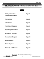
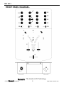
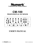
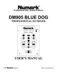
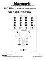
FRONT PANEL DIAGRAM...
3
12
18
19
13
4
16
9
15
5
10
1
14
21
7
20
6
2
8
11
17
- The Leader in DJ Technology
©1999
Industries
6
http://www.numark.com
PRO SM-1
FEATURES AND OPERATING INSTRUCTIONS...
Please read this entire manual before begining operation of the
P R O S M - 1 as there are new features you
will need to read about to use properly. This mixer can be 10” rack-mounted or used as a free-standing unit.
INSTALLATION AND OPERATION
Study the Connections Diagram on page 13. First, connect all stereo input sources. Next connect your microphone(s)
and monitor headphones. Make sure all faders are at "zero" and the unit is off. Connect the stereo outputs to the power
amplifier(s) and/or audio sources. Using the AC adpater plug the power source for the P R O S M - 1 into the unit. Now you
are ready to switch it on.
CHANNEL CONTROL FEATURES
1. Rotatable Input Toggle Switches select which
source will be active to that channel based on what you
have connected to the rear panel input section.
To rotate or replace the toggle
a. Turn off all power!
b. Remove 3 lower panel fader knobs
c. Unscrew 4 lower front panel screws found on
mixers sides and remove panel
d. Remove toggle switch retaining screws
e. To rotate, lift toggle and place in it’s new position.
If you are replacing the toggle switch, unplug the
old unit and plug in the new one.
f. Screw toggle back into place.
2. PFL Meters are 12-segment individual displays for the
input level of the corresponding channe. This allows the
DJ to accurately match channel levels with the Pre-Fader
gain controls before mixing them together. The idea is to
properly match PFL inputs, not the input with the stereo
output meter!
3. PFL Gain Controls are for accurately matching input
levels of the channels.
5. Balance Controls are for adjusting the stereo signals
intensity from right to left. Moving the slider to the left will
allow only the left side to be heard, moving the slider to the
right will allow only the right side to be heard, leaving it in
the middle creates an even stereo balance. The highresolution linear faders are great for creating quick effects.
6. The Active Channel Faders are highly reliable, longlife, Alps™ optical faders. These control individual source
levels in the mix after processing by the input gain and
channel EQ.
N o t e : The input faders are user replaceable in the
unlikely case of failure. Simply unscrew the four lower
faceplate screws and remove the faceplate. Then
unscrew the 2 screws which hold the fader in place, lift
it out and disconnect it’s cable. Re-attach the new
fader and screw the face plate back onto the unit.
You’re back in business!
7. The Channel Contour Control slide switch allows
the DJ to customize the way the Channel fader affects the
channel signal as it is used.
3 0 d B creates an even increase in volume as the
fader is moved upward
2 0 d B creates a more gradual volume increase
6dB
creates a very slow change at first and then very
rapid at the top of the fader
4. Treble, Middle, and Bass Controls are for setting
appropriate equalized levels for the music you are playing.
When turned all the way left they “CUT” the signal of the
associated frequency range by -30dB for special effects
mixing.
- The Leader in DJ Technology
©1999
Industries
7
http://www.numark.com
PRO SM-1
CROSSFADER SECTION
8. The Active Crossfader achieves clean segues
between the two input channels. "Hard left" selects
Channel 1. "Hard right" selects Channel 2. With the
crossfader centered, both channels are live and equal.
Use the crossfader for fast and seamless segues from one
selected channel to the other.
N o t e : The crossfader is user replaceable in case of
failure. Simply unscrew the four lower faceplate screws
and remove the faceplate. Then unscrew the 2 screws
which hold it in place, lift it out and disconnect it’s
cable. Re-attach the new crossfader and screw the
face plate back onto the unit.
9. The Crossfader Slope Adjust changes the rate at
which the two channels are blended together. Rotating to
the left creates an even blend of the two channels as the
crossfader is moved. Rotating all the way to the right
creates a very quick activation of the opposing channel’s
signal by the crossfader. This “QUICK CUT” is ideal for
creating transform effects with the crossfader.
10. The Crossfader Direction (Hamster) Toggle
allows the DJ to reverse direction of the crossfader. By
reversing direction, Channel 2 will be on the left and
Channel 1 will be on the right. This toggle may also be
used for various tricks.
MIC CONTROL SECTION
11. The Microphone Connector is located on the front
panel of the unit. It is a combination XLR-1/4” Neutrik™ jack
for flexible connection options.
12. The Microphone Gain Control adjusts the input
level of the microphone.
13. The Microphone Treble and Bass Controls are for
EQing your voice through the sound system. The controls
are detented for setting tone "flat". For best results, use a
dynamic cardioid microphone.
HEADPHONE/CUE SECTION
14. The Channel Cue Slider allows the DJ to preview
the pre-fader channels material through headphones.
Sliding this to the left plays the left channel and sliding to
the right plays the right channel. You can blend them in
the headphones by moving the slider to the middle.
15. The Program Mix (PGM) Control allows the DJ to
blend the cue slider material with the final output mix
including the microphone. When the knob is rotated left all
you will hear is the channel slider cue source, when the
knob is all the way right you will hear what is playing through
the master output. By blending, beats can be matched
exactly and segues can be smooth when a song is cued.
16. The Headphone Volume control adjusts the level
of the music heard in the headphones
17. The Headphone Connectors are located on the
front of the unit. Connect headphones with a standard 1/4"
stereo plug or 1/8” mini headphone plug.
MASTER/BOOTH OUTPUT SECTION
18. The Stereo Master Fader controls the overall
output level. This signal is sent to both the balanced and
unbalanced master output on the rear panel.
19. The Zone Level controls speaker volume for a
remote zone or booth monitors. If you do not use booth
monitors the output can feed a tape deck, another
amplifier, another mixer or a satellite speaker system. The
Zone output can be switched from stereo to mono by use
of a special rear panel switch. This enables the use of just
one speaker to hear the total output.
Note: This can also be used to supply line level audio to a
lighting controller or to lights that are sound activated.
20. Stereo Output Level Indicator. This inner dual
12-segment stereo meter tracks the output level.
It is OK to be “in the red” occasionally, as long as +5dB or
+8dB are not constantly lit. Set the crossover, equalizer
and power amp inputs to avoid distortion at each step in
the audio chain. Proper attention to the meter results in the
best possible sound without any audible distortion.
21. Power-On LED indicates power is supplied to the
mixer and the rear panel power switch is set to the on
position.
- The Leader in DJ Technology
©1999
Industries
8
http://www.numark.com
PRO SM-1
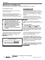
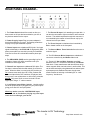
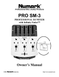
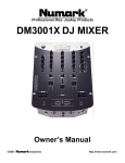
REAR PANEL DIAGRAM...
1
9
6
4
6
4
2
11 10 8 7
1. The Power Switch should be turned on after you
have turned on all input devices and before you turn on
any devices attached to the output.
2. Power Supply Input Plug your power adapter in
here before switching on power. See safety precautions
on page 3 for proper treatment of power.
3. Phono Inputs use unbalanced RCA jacks. Your input
signal is fed directly to the P R O S M - 1's high-quality RIAA
phono pre-amplifiers so use this input only for turntables.
Line level sources will overload the sensitive phono preamps.
4. The GROUNDS (GND) are the grounding lugs for all
turntables. Always use these connections with your
turntables to avoid signal hum.
5. Phono/Line Inputs are unbalanced RCA jacks. The
line input is selected with the slider switch (6) on the rear
panel. When the slider is moved to the line position you
can connect stereo audio from HiFi VCRs, cassette and
reel-to-reel tape decks, DAT machines, CD players, laser
discs, tuners, even synthesizers or other mixing consoles.
N O T E : Plug mono audio sources into both Left and
Right inputs using a “Y” cable connector.
5 3
5
3
7. The Record Output is for attaching your tape deck. It
can also be connected to light controllers or other external
devices. The audio that passes through this connector is
not controlled by the master so levels are set only by the
channel and mic input faders.
8. The Zone Output is unbalanced and controlled by
Zone Level control on the face panel.
9. The Stereo/Mono Zone Switch allows the user to
make the signal.
10. The RCA Stereo Main Outputs are unbalanced
connectors controlled by the Master fader knob.
11. These 1/4” Stereo Main Outputs are reliable
Balanced TRS 1/4” connectors controlled by the Master
fader knob. Power transformers and other devices which
cause magnetic fields can induce hum in audio cables. This
can be best resolved by using balanced lines where inputs
and outputs permit. Balanced lines are also the most
effective means of reducing or eliminating RF or “radio
frequency” interference.
6. Line/Phono Input Slider Switch. Use this to allow
line level equipment to be plugged into your phono inputs
giving you a total of 5 line input options.
Warning: make sure the LINE/PHONO input
switch is set to line before playing any line input
level devices through your mixer
- The Leader in DJ Technology
©1999
Industries
9
http://www.numark.com
PRO SM-1
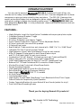
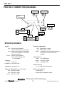
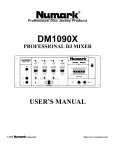
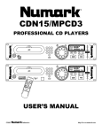
PRO SM-1 CONNECTION DIAGRAM...
Turntable 1
Turntable 3
Power
Transformer
Turntable 2
CD Player
Main
Sound System
w/ Amplifier
Tape Deck
Booth
Sound System
w/ Amplifier
SPECIFICATIONS...
Inputs:
Line: 10K ohm input impedance
75mV rms sensitivity for 1.22V output
Mic: 10Kohm input impedance unbalanced
2.5mV rms sensitivity for 1.22V output
50mV rms max input
Phono: 47Kohm imput impedance
1.2mV rms sensitivity @ 1KHz
for 1.22V output
Outputs:
Line: 9V rms max
Headphone: 0.5W into 47ohm
Frequency
Line:
Mic:
Phono:
Response:
20Hz-22KHz +/-0.5dB
20Hz-20KHz +/-0.5dB
+/-1dB except for controlled attenuation of
-3dB @ 20Hz to reduce rumble and
feedback
Channel EQ:
Bass: +12/-30dB @60Hz
Middle: +12/30 @ 1.36KHx
Treble: +12/30 @ 15KHz
Channel Curve:
-6, -20, -30dB at 50% fader position
Distortion: less than 0.01%
Signal to Noise Ratio: (maximum output)
Line: Better theb 90dB
Mic: Better then 78 dB
Phono: Better then 76dB
Power Consumption:
17 Watt typical
28 Watt with full headphone output
- The Leader in DJ Technology
©1999
Industries
10
http://www.numark.com
PRO SM-1
BLOCK DIAGRAM...
- The Leader in DJ Technology
©1999
Industries
11
http://www.numark.com
®
LIMITED PRODUCT WARRANTY
1. What is covered and for how long? NUMARK INDUSTRIES LCC ("NUMARK") warrants to the original purchaser that NUMARK'S DJ mixers
and amplifiers are free from defects in material and workmanship under normal use and service for the period commencing upon the date of
purchase from an authorized NUMARK dealer and continuing for the following period of time after that date for (2) Years. The warranty is
extended to (3) Years with the completion of the warranty card provided that the warranty card is completed and returned within (30) days from
the date of purchase.
All other NUMARK products are warranteed for (1) Year including but not limited to CD players, turntables, preamplifiers, beatkeepers, equalizers,
microphones, headphones, and all other accesories.
2. What is not covered? This Limited Warranty is conditioned upon proper use of the product by the purchaser.
This Limited Warranty does not cover: (a) defects or damage resulting from accident, misuse, abuse, neglect, unusual physical or electrical stress,
modification of any part of the product, or cosmetic damage; (b) equipment that has the serial number removed or made illegible; (c) all plastic
surfaces and other externally exposed parts that are scratched or damaged due to normal use; (d) defects or damage from improper testing,
operation, maintenance, installation, adjustment, or service of the mixers; (e) crossfaders.
3. What are NUMARK'S obligations? During the applicable warranty period, NUMARK will repair or replace, at NUMARK'S sole discretion,
without charge to the purchaser, any defective component part of the mixer. To obtain service under this Limited Warranty, purchaser must first
contact NUMARK and obtain a return authorization number ("RA#"). Purchaser must then return the mixer to NUMARK in an adequate container
for shipping, accompanied by purchaser's sales receipt or comparable proof of sale showing the date of purchase, the serial number of the product,
and the seller's name and address. To obtain an RA# and assistance on where to return the mixer, contact NUMARK customer service at 401-2959000. Upon receipt, NUMARK will repair or replace the defective products. NUMARK may, at NUMARK'S sole discretion, use rebuilt,
reconditioned, or new parts or components when repairing any product or replace a product with a rebuilt, reconditioned or new product.
Repaired mixers will be warranted for a period equal to the remainder of the original Limited Warranty on the original mixer or for (90) days,
whichever is longer. All replaced parts, components, boards and equipment become the property of NUMARK. If NUMARK determines that any
mixer is not covered by this Limited Warranty, purchaser must pay all parts, shipping, and labor charges for the repair or return of such mixer.
4. What are the limits on NUMARK'S liabilities? THE WARRANTIES GIVEN IN THIS LIMITED WARRANTY, TOGETHER WITH ANY IMPLIED
WARRANTIES COVERING NUMARK MIXERS, INCLUDING WITHOUT LIMITATION ANY WARRANTIES OF MERCHANTABILITY OR FITNESS
FOR A PARTICULAR PURPOSE, ARE LIMITED TO THE DURATION OF THIS LIMITED WARRANTY. EXCEPT TO THE EXTENT PROHIBITED BY
APPLICABLE LAW, NUMARK SHALL NOT BE LIABLE FOR ANY SPECIAL, INCIDENTAL, CONSEQUENTIAL, INDIRECT OR SIMILAR
DAMAGES, LOSS OF PROFITS, DAMAGES TO PURCHASER'S PROPERTY, OR INJURY TO PURCHASER OR OTHERS ARISING OUT OF THE
USE, MISUSE OR INABILITY TO USE ANY NUMARK MIXER, BREACH OF WARRANTY, OR NEGLIGENCE, INCLUDING BUT NOT LIMITED TO
NUMARK'S OWN NEGLIGENCE, EVEN IF NUMARK OR ITS AGENT HAS BEEN ADVISED OF SUCH DAMAGES, OR FOR ANY CLAIM
BROUGHT AGAINST PURCHASER BY ANY OTHER PARTY. THIS LIMITED WARRANTY IS THE COMPLETE WARRANTY FOR NUMARK'S
MIXERS, AND IS GIVEN IN LIEU OF ALL OTHER EXPRESS WARRANTIES. THIS LIMITED WARRANTY SHALL NOT EXTEND TO ANYONE
OTHER THAN THE ORIGINAL PURCHASER OF THIS PRODUCT AND STATES PURCHASER'S EXCLUSIVE REMEDY. IF ANY PORTION OF THIS
LIMITED WARRANTY IS ILLEGAL OR UNENFORCEABLE BY REASON OF ANY LAW, SUCH PARTIAL ILLEGALITY OR UNENFORCEABILTY
SHALL NOT AFFECT THE ENFORCEABILITY OF THE REMAINDER OF THIS LIMITED WARRANTY WHICH PURCHASER ACKNOWLEDGES IS
AND WILL ALWAYS BE CONSTRUED TO BE LIMITED BY ITS TERMS OR AS LIMITED AS THE LAW PERMITS.
This Limited Warranty allocates risk of product failure between purchaser and NUMARK, and NUMARK'S product pricing reflects this allocation of
risk and the limitations of liability contained in this Limited Warranty. The agents, employees, distributors, and dealers of NUMARK are not
authorized to make modifications to this Limited Warranty, or make additional warranties binding on NUMARK. Accordingly, additional statements
such as dealer advertising or presentation, whether oral or written, do not constitute warranties by NUMARK and should not be relied upon.
5. How does state law apply to this warranty? SOME STATES DO NOT ALLOW THE EXCLUSION OR LIMITATIONS OF INCIDENTAL OR
CONSEQUENTIAL DAMAGES OR HOW LONG AN IMPLIED WARRANTY LASTS, SO THE ABOVE LIMITATIONS OR EXCLUSIONS MAY NOT
APPLY TO PURCHASER.
This Limited Warranty gives you specific legal rights. You may also have other rights, which vary from one jurisdiction to another.
RETURN INFORMATION
1. A Return Authorization number must be obtained from Numark through the address or phone numbers below.
2. A copy of the original sales receipt must also be included for the equipment to be repaired under warranty.
3. The faulty equipment must be packed in its original packaging.
4. One additional outer layer of packaging must be included to ensure product safety. Failure to do so may inadequately protect the
equipment in transit and, therefore, jeopardize the customer’s warranty.
5. Numark will not accept COD shipments and no call tags will be issued for merchandise return.
6. Numark will not return repaired merchandise to customers by priority service, unless by written request at the customer’s cost.
Requests must be submited in writing with merchandise returned.
7. The defective Numark equipment should be sent, FREIGHT PREPAID with Return Authorization number clearly printed on the outer
packaging and original sales receipt enclosed to:
INDUSTRIES
Attention: Service Department
11 Helmsman Avenue
North Kingstown, RI 02852 USA
Phone:
Fax:
E-mail:
+1 (401) 295-9000
+1 (401) 295-5200
[email protected]