1
Version 7.05.300
NN46110-313 02.01
314961-G Rev 01
November 2007
Standard
600 Technology Park Drive
Billerica, MA 01821-4130
Nortel VPN Router Installation
— VPN Router 1010/1050/1100
2
Copyright © 2007 Nortel Networks. All rights reserved.
The information in this document is subject to change without notice. The statements, configurations, technical data, and
recommendations in this document are believed to be accurate and reliable, but are presented without express or implied
warranty. Users must take full responsibility for their applications of any products specified in this document. The
information in this document is proprietary to Nortel Networks Inc.
Trademarks
Nortel, the Nortel logo, the Globemark, and Contivity are trademarks of Nortel Networks.
Adobe and Acrobat Reader are trademarks of Adobe Systems Incorporated.
Celeron and Intel are trademarks of Intel Corporation.
All other trademarks are the property of their respective owners.
Statement of conditions
In the interest of improving internal design, operational function, and/or reliability, Nortel Networks Inc. reserves the
right to make changes to the products described in this document without notice.
Nortel Networks Inc. does not assume any liability that may occur due to the use or application of the product(s) or
circuit layout(s) described herein.
USA requirements only
Federal Communications Commission (FCC) Compliance Notice: Radio Frequency Notice
This device complies with Part 15 of the FCC Rules. Operation is subject to the following two conditions:
•
•
This device may not cause harmful interference.
This device must accept any interference received, including interference that may cause undesired operation.
Note: This equipment has been tested and found to comply with the limits for a Class B digital device, pursuant to
Part 15 of the FCC Rules. These limits are designed to provide reasonable protection against harmful interference in a
residential installation. This equipment generates, uses and can radiate radio frequency energy and, if not installed and
used in accordance with the instructions, may cause harmful interference to radio communications. However, there is no
guarantee that interference will not occur in a particular installation. If this equipment does cause harmful interference to
radio or television reception, which can be determined by turning the equipment off and on, the user is encouraged to try
to correct the interference by one or more of the following measures:
•
•
•
•
Reorient or relocate the receiving antenna.
Increase the separation between the equipment and receiver.
Connect the equipment into an outlet on a circuit different from that to which the receiver is connected.
Consult the dealer or an experienced radio/TV technician for help.
European requirements only
EN 55 022 statement
This is to certify that the Nortel Networks VPN Router 1010/1050/1100 is shielded against the generation of radio
interference in accordance with the application of Council Directive 89/336/EEC, Article 4a. Conformity is declared by
the application of EN 55 022 Class B (CISPR 22).
NN46110-313 02.01
3
EC Declaration of Conformity
This product conforms (or these products conform) to the provisions of the R&TTE Directive 1999/5/EC.
Japan/Nippon requirements only
Denan statement
Voluntary Control Council for Interference (VCCI) statement (Class B)
Canada requirements only
Canadian Department of Communications Radio Interference Regulations
This digital apparatus (VPN Router 1010/1050/1100) does not exceed the Class B limits for radio-noise emissions from
digital apparatus as set out in the Radio Interference Regulations of the Canadian Department of Communications.
Règlement sur le brouillage radioélectrique du ministère des Communications
Cet appareil numérique (VPN Router 1010/1050/1100) respecte les limites de bruits radioélectriques visant les appareils
numériques de classe B prescrites dans le Règlement sur le brouillage radioélectrique du ministère des Communications
du Canada.
Nortel Networks Inc. software license agreement
This Software License Agreement (“License Agreement”) is between you, the end-user (“Customer”) and Nortel
Networks Corporation and its subsidiaries and affiliates (“Nortel Networks”). PLEASE READ THE FOLLOWING
CAREFULLY. YOU MUST ACCEPT THESE LICENSE TERMS IN ORDER TO DOWNLOAD AND/OR USE THE
SOFTWARE. USE OF THE SOFTWARE CONSTITUTES YOUR ACCEPTANCE OF THIS LICENSE
AGREEMENT. If you do not accept these terms and conditions, return the Software, unused and in the original shipping
container, within 30 days of purchase to obtain a credit for the full purchase price.
Nortel VPN Router Installation — VPN Router 1010/1050/1100
4
“Software” is owned or licensed by Nortel Networks, its parent or one of its subsidiaries or affiliates, and is copyrighted
and licensed, not sold. Software consists of machine-readable instructions, its components, data, audio-visual content
(such as images, text, recordings or pictures) and related licensed materials including all whole or partial copies. Nortel
Networks grants you a license to use the Software only in the country where you acquired the Software. You obtain no
rights other than those granted to you under this License Agreement. You are responsible for the selection of the
Software and for the installation of, use of, and results obtained from the Software.
1. Licensed Use of Software. Nortel Networks grants Customer a nonexclusive license to use a copy of the Software
on only one machine at any one time or to the extent of the activation or authorized usage level, whichever is applicable.
To the extent Software is furnished for use with designated hardware or Customer furnished equipment (“CFE”),
Customer is granted a nonexclusive license to use Software only on such hardware or CFE, as applicable. Software
contains trade secrets and Customer agrees to treat Software as confidential information using the same care and
discretion Customer uses with its own similar information that it does not wish to disclose, publish or disseminate.
Customer will ensure that anyone who uses the Software does so only in compliance with the terms of this Agreement.
Customer shall not a) use, copy, modify, transfer or distribute the Software except as expressly authorized; b) reverse
assemble, reverse compile, reverse engineer or otherwise translate the Software; c) create derivative works or
modifications unless expressly authorized; or d) sublicense, rent or lease the Software. Licensors of intellectual property
to Nortel Networks are beneficiaries of this provision. Upon termination or breach of the license by Customer or in the
event designated hardware or CFE is no longer in use, Customer will promptly return the Software to Nortel Networks or
certify its destruction. Nortel Networks may audit by remote polling or other reasonable means to determine Customer’s
Software activation or usage levels. If suppliers of third party software included in Software require Nortel Networks to
include additional or different terms, Customer agrees to abide by such terms provided by Nortel Networks with respect
to such third party software.
2. Warranty. Except as may be otherwise expressly agreed to in writing between Nortel Networks and Customer,
Software is provided “AS IS” without any warranties (conditions) of any kind. NORTEL NETWORKS DISCLAIMS
ALL WARRANTIES (CONDITIONS) FOR THE SOFTWARE, EITHER EXPRESS OR IMPLIED, INCLUDING,
BUT NOT LIMITED TO THE IMPLIED WARRANTIES OF MERCHANTABILITY AND FITNESS FOR A
PARTICULAR PURPOSE AND ANY WARRANTY OF NON-INFRINGEMENT. Nortel Networks is not obligated to
provide support of any kind for the Software. Some jurisdictions do not allow exclusion of implied warranties, and, in
such event, the above exclusions may not apply.
3. Limitation of Remedies. IN NO EVENT SHALL NORTEL NETWORKS OR ITS AGENTS OR SUPPLIERS BE
LIABLE FOR ANY OF THE FOLLOWING: a) DAMAGES BASED ON ANY THIRD PARTY CLAIM; b) LOSS OF,
OR DAMAGE TO, CUSTOMER’S RECORDS, FILES OR DATA; OR c) DIRECT, INDIRECT, SPECIAL,
INCIDENTAL, PUNITIVE, OR CONSEQUENTIAL DAMAGES (INCLUDING LOST PROFITS OR SAVINGS),
WHETHER IN CONTRACT, TORT OR OTHERWISE (INCLUDING NEGLIGENCE) ARISING OUT OF YOUR
USE OF THE SOFTWARE, EVEN IF NORTEL NETWORKS, ITS AGENTS OR SUPPLIERS HAVE BEEN
ADVISED OF THEIR POSSIBILITY. The forgoing limitations of remedies also apply to any developer and/or supplier
of the Software. Such developer and/or supplier is an intended beneficiary of this Section. Some jurisdictions do not
allow these limitations or exclusions and, in such event, they may not apply.
4.
General
a.
If Customer is the United States Government, the following paragraph shall apply: All Nortel Networks
Software available under this License Agreement is commercial computer software and commercial computer
software documentation and, in the event Software is licensed for or on behalf of the United States
Government, the respective rights to the software and software documentation are governed by Nortel
Networks standard commercial license in accordance with U.S. Federal Regulations at 48 C.F.R. Sections
12.212 (for non-DoD entities) and 48 C.F.R. 227.7202 (for DoD entities).
b.
Customer may terminate the license at any time. Nortel Networks may terminate the license if Customer fails
to comply with the terms and conditions of this license. In either event, upon termination, Customer must
either return the Software to Nortel Networks or certify its destruction.
NN46110-313 02.01
5
c.
Customer is responsible for payment of any taxes, including personal property taxes, resulting from
Customer’s use of the Software. Customer agrees to comply with all applicable laws including all applicable
export and import laws and regulations.
d.
Neither party may bring an action, regardless of form, more than two years after the cause of the action arose.
e.
The terms and conditions of this License Agreement form the complete and exclusive agreement between
Customer and Nortel Networks.
f.
This License Agreement is governed by the laws of the country in which Customer acquires the Software. If
the Software is acquired in the United States, then this License Agreement is governed by the laws of the state
of New York.
Nortel VPN Router Installation — VPN Router 1010/1050/1100
6
NN46110-313 02.01
7
Contents
New in this release. . . . . . . . . . . . . . . . . . . . . . . . . . . . . . . . . . . . . . . . . . . . . 13
Features . . . . . . . . . . . . . . . . . . . . . . . . . . . . . . . . . . . . . . . . . . . . . . . . . . . . . . . . . . . . 13
1000BASE-T (1000 GT) Ethernet card . . . . . . . . . . . . . . . . . . . . . . . . . . . . . . . . . 13
How to get help . . . . . . . . . . . . . . . . . . . . . . . . . . . . . . . . . . . . . . . . . . . . . . . 15
Finding the latest updates on the Nortel Web site . . . . . . . . . . . . . . . . . . . . . . . . . . . . 15
Getting help from the Nortel Web site . . . . . . . . . . . . . . . . . . . . . . . . . . . . . . . . . . . . . 15
Getting help over the phone from a Nortel Solutions Center . . . . . . . . . . . . . . . . . . . . 16
Getting help from a specialist by using an Express Routing Code . . . . . . . . . . . . . . . 16
Getting help through a Nortel distributor or reseller . . . . . . . . . . . . . . . . . . . . . . . . . . . 16
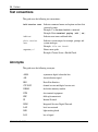
Preface . . . . . . . . . . . . . . . . . . . . . . . . . . . . . . . . . . . . . . . . . . . . . . . . . . . . . . 17
Before you begin . . . . . . . . . . . . . . . . . . . . . . . . . . . . . . . . . . . . . . . . . . . . . . . . . . . . . 17
Text conventions . . . . . . . . . . . . . . . . . . . . . . . . . . . . . . . . . . . . . . . . . . . . . . . . . . . . . 18
Acronyms . . . . . . . . . . . . . . . . . . . . . . . . . . . . . . . . . . . . . . . . . . . . . . . . . . . . . . . . . . . 18
Related publications . . . . . . . . . . . . . . . . . . . . . . . . . . . . . . . . . . . . . . . . . . . . . . . . . . . 19
Printed technical manuals . . . . . . . . . . . . . . . . . . . . . . . . . . . . . . . . . . . . . . . . . . . . . . 20
Chapter 1
Hardware overview . . . . . . . . . . . . . . . . . . . . . . . . . . . . . . . . . . . . . . . . . . . . 21
Internal LAN connections (LAN 0 and LAN 1) . . . . . . . . . . . . . . . . . . . . . . . . . . . . . . . 23
Rear view of the gateway . . . . . . . . . . . . . . . . . . . . . . . . . . . . . . . . . . . . . . . . . . . . . . . 25
Connecting the power cord . . . . . . . . . . . . . . . . . . . . . . . . . . . . . . . . . . . . . . . . . . . . . 26
Understanding the LEDs . . . . . . . . . . . . . . . . . . . . . . . . . . . . . . . . . . . . . . . . . . . . . . . 27
Front panel LEDs . . . . . . . . . . . . . . . . . . . . . . . . . . . . . . . . . . . . . . . . . . . . . . . . . . 27
Ethernet port LEDs . . . . . . . . . . . . . . . . . . . . . . . . . . . . . . . . . . . . . . . . . . . . . . . . 28
10/100BASE-TX Ethernet interface card LEDs . . . . . . . . . . . . . . . . . . . . . . . . . . . 29
Nortel VPN Router Installation — VPN Router 1010/1050/1100
8
Contents
1000BASE-T (1000 GT) Ethernet interface card LEDs . . . . . . . . . . . . . . . . . . . . . 30
56/64K CSU/DSU WAN interface card LEDs . . . . . . . . . . . . . . . . . . . . . . . . . . . . 31
ADSL WAN interface card LEDs . . . . . . . . . . . . . . . . . . . . . . . . . . . . . . . . . . . . . . 31
T1/E1 CSU/DSU WAN interface card LEDs . . . . . . . . . . . . . . . . . . . . . . . . . . . . . 32
Single V.35/X.21 WAN interface card LEDs . . . . . . . . . . . . . . . . . . . . . . . . . . . . . 33
Chapter 2
Installing option cards in the Nortel VPN Router 600 1100 . . . . . . . . . . . . 35
Appendix A
Technical specifications . . . . . . . . . . . . . . . . . . . . . . . . . . . . . . . . . . . . . . . . 41
Chassis specifications . . . . . . . . . . . . . . . . . . . . . . . . . . . . . . . . . . . . . . . . . . . . . . . . . 41
System ports . . . . . . . . . . . . . . . . . . . . . . . . . . . . . . . . . . . . . . . . . . . . . . . . . . . . . . . . 42
10/100BASE-TX Ethernet LAN ports . . . . . . . . . . . . . . . . . . . . . . . . . . . . . . . . . . . 42
Serial port . . . . . . . . . . . . . . . . . . . . . . . . . . . . . . . . . . . . . . . . . . . . . . . . . . . . . . . 43
External modem adapter . . . . . . . . . . . . . . . . . . . . . . . . . . . . . . . . . . . . . . . . . . . . 45
Hardware option cards . . . . . . . . . . . . . . . . . . . . . . . . . . . . . . . . . . . . . . . . . . . . . . . . . 46
10/100BASE-TX Ethernet interface card . . . . . . . . . . . . . . . . . . . . . . . . . . . . . . . . 47
1000BASE-T (1000 GT) Ethernet interface card . . . . . . . . . . . . . . . . . . . . . . . . . . 47
56/64K CSU/DSU WAN interface card . . . . . . . . . . . . . . . . . . . . . . . . . . . . . . . . . 49
ADSL WAN interface card . . . . . . . . . . . . . . . . . . . . . . . . . . . . . . . . . . . . . . . . . . . 51
ISDN BRI interface card . . . . . . . . . . . . . . . . . . . . . . . . . . . . . . . . . . . . . . . . . . . . 52
T1/E1 CSU/DSU WAN interface card . . . . . . . . . . . . . . . . . . . . . . . . . . . . . . . . . . 54
V.90 modem interface card . . . . . . . . . . . . . . . . . . . . . . . . . . . . . . . . . . . . . . . . . . 56
Single V.35/X.21 WAN interface card . . . . . . . . . . . . . . . . . . . . . . . . . . . . . . . . . . 57
Index . . . . . . . . . . . . . . . . . . . . . . . . . . . . . . . . . . . . . . . . . . . . . . . . . . . . . . . . 61
NN46110-313 02.01
9
Figures
Figure 1
VPN Router 600 1010/1050/1100 series . . . . . . . . . . . . . . . . . . . . . . . . . 21
Figure 2
VPN Router 600 1010 front view . . . . . . . . . . . . . . . . . . . . . . . . . . . . . . . 23
Figure 3
VPN Router 600 1050 front view . . . . . . . . . . . . . . . . . . . . . . . . . . . . . . . 24
Figure 4
VPN Router 600 1100 front view . . . . . . . . . . . . . . . . . . . . . . . . . . . . . . . 24
Figure 5
Rear view of the VPN Router 600 1010/1050/1100 . . . . . . . . . . . . . . . . . 25
Figure 6
Front panel of the VPN Router 600 1010 . . . . . . . . . . . . . . . . . . . . . . . . . 28
Figure 7
LEDs on the 10/100BASE-TX Ethernet interface card . . . . . . . . . . . . . . . 29
Figure 8
LEDs on the full-height 1000BASE-T (1000 GT) Ethernet interface card . 30
Figure 9
LEDs on the half-height 1000BASE-T (1000 GT) Ethernet card . . . . . . . 30
Figure 10
LEDs on the 56/64K CSU/DSU WAN interface card . . . . . . . . . . . . . . . . 31
Figure 11
LEDs on the ADSL WAN interface card . . . . . . . . . . . . . . . . . . . . . . . . . . 31
Figure 12
LEDs on the T1/E1 CSU/DSU WAN interface card . . . . . . . . . . . . . . . . . 32
Figure 13
LEDs on the single V.35/X.21 WAN interface card . . . . . . . . . . . . . . . . . . 33
Figure 14
VPN Router 600 1100 system board . . . . . . . . . . . . . . . . . . . . . . . . . . . . 37
Figure 15
Serial cable (RJ-45-to-DB9) . . . . . . . . . . . . . . . . . . . . . . . . . . . . . . . . . . . 44
Figure 16
Serial cable adapter for connection to modem (DB9-to-DB25) . . . . . . . . 45
Figure 17
10/100BASE-TX Ethernet interface card . . . . . . . . . . . . . . . . . . . . . . . . . 47
Figure 18
VPN Router 1100 full-height 1000BASE-T (1000 GT) . . . . . . . . . . . . . . . 48
Figure 19
VPN Router 1100 half-height 1000BASE-T (1000 GT) . . . . . . . . . . . . . . . 48
Figure 20
56/64K CSU/DSU WAN interface card . . . . . . . . . . . . . . . . . . . . . . . . . . . 49
Figure 21
ADSL WAN interface card . . . . . . . . . . . . . . . . . . . . . . . . . . . . . . . . . . . . 51
Figure 22
ISDN BRI S/T interface card . . . . . . . . . . . . . . . . . . . . . . . . . . . . . . . . . . . 52
Figure 23
ISDN BRI U interface card . . . . . . . . . . . . . . . . . . . . . . . . . . . . . . . . . . . . 52
Figure 24
T1/E1 CSU/DSU WAN interface card . . . . . . . . . . . . . . . . . . . . . . . . . . . . 54
Figure 25
V.90 modem interface card . . . . . . . . . . . . . . . . . . . . . . . . . . . . . . . . . . . . 56
Figure 26
Single V.35/X.21 WAN interface card . . . . . . . . . . . . . . . . . . . . . . . . . . . . 57
Nortel VPN Router Installation — VPN Router 1010/1050/1100
10
Figures
NN46110-313 02.01
11
Tables
Table 1
Items shipped with the VPN Router 600 1010, 1050, and 1100 . . . . . . . . 22
Table 2
Power cord requirements . . . . . . . . . . . . . . . . . . . . . . . . . . . . . . . . . . . . . 26
Table 3
Front panel LED indicators . . . . . . . . . . . . . . . . . . . . . . . . . . . . . . . . . . . . 28
Table 4
Ethernet port LED indicators . . . . . . . . . . . . . . . . . . . . . . . . . . . . . . . . . . 29
Table 5
LED indicators on the 10/100BASE-TX Ethernet interface card . . . . . . . . 29
Table 6
LED indicators on the 1000BASE-T (1000 GT) Ethernet interface card . . 30
Table 7
LED indicators on the 56/64K CSU/DSU WAN interface card . . . . . . . . . 31
Table 8
LED indicators on the ADSL WAN interface card . . . . . . . . . . . . . . . . . . . 32
Table 9
LED indicators on the T1/E1 CSU/DSU WAN interface card . . . . . . . . . . 33
Table 10
LED indicators on the single V.35/X.21 WAN interface card . . . . . . . . . . 33
Table 11
Supported option cards for the Nortel VPN Router 600 1100 . . . . . . . . . . 35
Table 12
Physical specifications . . . . . . . . . . . . . . . . . . . . . . . . . . . . . . . . . . . . . . . 41
Table 13
Electrical and environmental specifications . . . . . . . . . . . . . . . . . . . . . . . 41
Table 14
10/100BASE-TX Ethernet port pinouts . . . . . . . . . . . . . . . . . . . . . . . . . . . 43
Table 15
RJ-45 to DB9 pinouts . . . . . . . . . . . . . . . . . . . . . . . . . . . . . . . . . . . . . . . . 44
Table 16
Null modem adapter cable pinouts . . . . . . . . . . . . . . . . . . . . . . . . . . . . . . 45
Table 17
1000BASE-T (1000 GT) Ethernet pinouts . . . . . . . . . . . . . . . . . . . . . . . . 49
Table 18
56/64K CSU/DSU cable pinouts for crossover connection . . . . . . . . . . . . 50
Table 19
56/64K CSU/DSU cable pinouts for straight-through connection . . . . . . . 51
Table 20
ADSL cable pinouts . . . . . . . . . . . . . . . . . . . . . . . . . . . . . . . . . . . . . . . . . 52
Table 21
ISDN BRI S/T cable pinouts . . . . . . . . . . . . . . . . . . . . . . . . . . . . . . . . . . . 53
Table 22
ISDN BRI U cable pinouts . . . . . . . . . . . . . . . . . . . . . . . . . . . . . . . . . . . . 53
Table 23
T1/E1 CSU/DSU cable pinouts for crossover connection . . . . . . . . . . . . . 55
Table 24
T1/E1 CSU/DSU cable pinouts for straight-through connection . . . . . . . . 55
Table 25
V.90 modem cable pinouts . . . . . . . . . . . . . . . . . . . . . . . . . . . . . . . . . . . . 56
Table 26
V.35 cable pinouts . . . . . . . . . . . . . . . . . . . . . . . . . . . . . . . . . . . . . . . . . . 57
Table 27
X.21 cable pinouts . . . . . . . . . . . . . . . . . . . . . . . . . . . . . . . . . . . . . . . . . . 59
Nortel VPN Router Installation — VPN Router 1010/1050/1100
12
Tables
NN46110-313 02.01
13
New in this release
The following section details what’s new in Nortel VPN Router Installation—
VPN Router 1010/1050/1100 (NN46110-313) for Release 7.05.300:
Features
See the following section for information about feature changes:
1000BASE-T (1000 GT) Ethernet card
The 1000BASE-T (1000 GT) Ethernet card replaces the 10/100BASE-TX
Ethernet card. See “1000BASE-T (1000 GT) Ethernet interface card LEDs” on
page 30 and “1000BASE-T (1000 GT) Ethernet interface card” on page 47.
Nortel VPN Router Installation — VPN Router 1010/1050/1100
14
New in this release
NN46110-313 02.01
15
How to get help
This chapter explains how to get help for Nortel products and services.
Finding the latest updates on the Nortel Web site
The content of this documentation was current at the time the product was
released. To check for updates to the latest documentation and software for VPN
Router, go to:
www.nortel.com/support
Select Security & VPN and then, in the section called Virtual Private Networking
(VPN), IPSEC, and SSL, click the appropriate VPN Router product.
Getting help from the Nortel Web site
The best way to get technical support for Nortel products is from the Nortel
Technical Support Web site:
www.nortel.com/support
This site provides quick access to software, documentation, bulletins, and tools to
address issues with Nortel products. From this site you can:
•
•
•
•
download software, documentation, and product bulletins
search the Technical Support site and the Nortel Knowledge Base for answers
to technical issues
sign up for automatic notification of new software and documentation for
Nortel equipment
open and manage technical support cases
Nortel VPN Router Installation — VPN Router 1010/1050/1100
16
How to get help
Getting help over the phone from a Nortel Solutions
Center
If you do not find the information you require on the Nortel Technical Support
Web site, and you have a Nortel support contract, you can also get help over the
phone from a Nortel Solutions Center.
In North America, call 1-800-4NORTEL (1-800-466-7835).
Outside North America, go to the following Web site to obtain the phone number
for your region:
www.nortel.com/callus
Getting help from a specialist by using an Express
Routing Code
To access some Nortel Technical Solutions Centers, you can use an Express
Routing Code (ERC) to quickly route your call to a specialist in your Nortel
product or service. To locate the ERC for your product or service, go to:
www.nortel.com/erc
Getting help through a Nortel distributor or reseller
If you purchased a service contract for your Nortel product from a distributor or
authorized reseller, contact the technical support staff for that distributor or
reseller.
NN46110-313 02.01
17
Preface
The VPN Router 1010, 1050, and 1100 are part of the Nortel VPN Router system.
Nortel VPN Routers support secure, reliable IP VPNs in a single, integrated
hardware device. Throughout this guide, the VPN Router 1010, 1050, and 1100
are also referred to collectively as the gateway.
This guide provides instructions about how to install the VPN Router 1010, 1050,
and 1100 and about how to install and replace option cards in the VPN Router
1100. This guide also includes technical specifications.
For complete information about configuring and monitoring the VPN Router
1010, 1050, and 1100, see the documentation on the software CD. (For
information about VPN Router documentation, see “Related publications” on
page 19.)
Before you begin
This guide is intended for qualified service personnel who are installing the VPN
Router 1010, 1050, or 1100 for the first time or who need to install or replace an
option card in the VPN Router 1100.
Note: Before you install the VPN Router 1010, 1050, or 1100, use
standard cable system practices to install all network wiring on the
premises.
Nortel VPN Router Installation — VPN Router 1010/1050/1100
18
Preface
Text conventions
This guide uses the following text conventions:
bold Courier text
Indicates command names and options and text that
you need to enter.
Example: Use the show health command.
Example: Enter terminal paging {off | on}.
italic text
Indicates new terms and book titles.
plain Courier
text
Indicates system output, for example, prompts and
system messages.
Example: File not found.
separator ( > )
Shows menu paths.
Example: Choose Status > Health Check.
Acronyms
This guide uses the following acronyms:
ADSL
asymmetric digital subscriber line
AIS
alarm indication signal
BRI
Basic Rate Interface
CSU/DSU
channel service unit/digital service unit
DIMM
dual inline memory module
DTE
data terminal equipment
FRU
field replacement unit
IP
Internet Protocol
ISDN
Integrated Services Digital Network
LAN
local area network
LED
light emitting diode
LOS
loss of signal
NN46110-313 02.01
Preface
MAC
media access control
MDI-X
medium dependent interface crossover
OOF
out of frame
PCI
peripheral component interconnect
URL
uniform resource locator
VPN
virtual private network
WAN
wide area network
19
Related publications
For more information about using the VPN Router 1010, 1050, and 1100
(formerly known as the Contivity Secure IP Services Gateway 1010, 1050, and
1100), refer to the following publications (included on the VPN Router software
CD):
•
•
•
•
•
•
Release notes provide the latest information, including brief descriptions of
the new features, problems fixed in this release, and known problems and
workarounds.
Read Me First: Connecting for VPN Access (314962-C) describes how to set
up the VPN Router 1010/1050/1100 for basic Internet and VPN access.
Nortel VPN Router Configuration — Basic Features (NN46110-500)
introduces the product and provides information about initial configuration.
Nortel VPN Router Security — Servers, Authentication, and Certificates
(NN46110-600) provides instructions for configuring authentication servers
and services, as well as digital certificates.
Nortel VPN Router Security — Firewalls, Filters, NAT, and QoS
(NN46110-601) provides instructions for configuring the VPN Router
Stateful Firewall, NAT, and VPN Router interface and tunnel filters.
Nortel VPN Router Configuration — Tunneling Protocols (NN46110-503)
provides instructions for configuring the tunneling protocols IPsec, L2TP,
PPTP, and L2F.
Nortel VPN Router Installation — VPN Router 1010/1050/1100
20
Preface
•
•
•
•
•
•
Nortel VPN Router Configuration — Advanced Features (NN46110-502)
provides instructions for configuring 802.1Q VLANs, circuitless IP, advanced
WAN settings, PPP, PPPoE, frame relay, ADSL and ATM, T1/E1 CSU/DSU
interfaces, dial services and BIS, DLSw, IPX, and Hardware Accelerator
cards.
Nortel VPN Router Configuration — Routing (NN46110-504) provides
instructions for configuring RIP, OSPF, and VRRP, as well as instructions for
configuring ECMP, routing policy services, and client address redistribution.
Nortel VPN Router Configuration — SSL VPN Services (NN46110-501)
provides instructions for configuring services on the SSL VPN Module 1000,
including authentication, networks, user groups, and portal links.
Nortel VPN Router Using the Command Line Interface (NN46110-507)
provides syntax, descriptions, and examples for the commands that you can
use to configure, manage, and monitor the gateway.
Nortel VPN Router Troubleshooting (NN46110-602) provides information
about backup and recovery, file management, upgrading software, and
troubleshooting. This guide also provides instructions for monitoring gateway
status and performance.
Nortel VPN Router Configuration — TunnelGuard (NN46110-307) provides
information about configuring and using the TunnelGuard feature.
Printed technical manuals
You can print selected technical manuals and release notes free, directly from the
Internet. Go to www.nortel.com/documentation, find the product for which you
need documentation, then locate the specific category and model or version for
your hardware or software product. Use Adobe Reader to open the manuals and
release notes, search for the sections you need, and print them on most standard
printers. Go to Adobe Systems at www.adobe.com to download a free copy of the
Adobe Reader.
NN46110-313 02.01
21
Chapter 1
Hardware overview
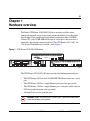
The Nortel VPN Router 1010/1050/1100 series provides scalable, secure,
manageable extranet access for up to five concurrent tunnels across the public
data network. These models are based on Intel architecture with a 300 MHz
Celeron CPU and 128 MB SDRAM. Instead of a hard drive, this series uses a
removable, upgradeable compact flash card. The VPN Router 1010, 1050, and
1100 fit on a bookshelf or on a shelf in a rack (Figure 1).
Figure 1 VPN Router 1010/1050/1100 series
LAN 0
LAN 1
Console
VPN Router 1010
VPN Router 1050
A
B
C
D
LAN 1
VPN Router 1100
LAN 0
Console
A
B
C
D
LAN 1
Console
LAN 0
10674EA
The VPN Router 1010/1050/1100 series provides the following network ports:
•
•
•
•
The VPN Router 1010 has dual 10/100BASE-TX Ethernet ports and a serial
port.
The VPN Router 1050 has a single Ethernet port and a four-port switch.
The VPN Router 1100 has a single Ethernet port, a four-port switch, and two
PCI slots (purchase option cards separately).
All models have a serial (console) port.
Caution: Route all cabling for all WAN, LAN, and serial connections
inside the building environment.
Nortel VPN Router Installation — VPN Router 1010/1050/1100
22 Chapter 1 Hardware overview
Table 1 lists the hardware accessories and other items shipped with the VPN
Router 1010, 1050, and 1100.
Note: Nortel does not ship a power cord with the VPN Router unless
you order one.
Table 1 Items shipped with the VPN Router 1010, 1050, and 1100
Description
Quantity
VPN Router 1010/1050/1100
1
Molded serial cable RJ-45 to DB91
1
AC to DC external power supply
1
VPN Router CD (contains documentation)
1
Ethernet crossover cable (VPN Router 1010 only)
1
Power cord (if ordered separately)
1
1 To connect the gateway to a modem, you can order a null modem adapter.
Inspect all items for shipping damage. If you detect any damage, do not install the
VPN Router 1010/1050/1100. Call the Nortel Technical Solutions Center in your
area (“How to get help” on page 15).
NN46110-313 02.01
Chapter 1 Hardware overview 23
Internal LAN connections (LAN 0 and LAN 1)
The VPN Router 1010, 1050, and 1100 have two internal LANs built in:
•
•
LAN 0 is the private LAN and also the LAN to use for Web management.
LAN 1 defaults to a public LAN. The software refers to the LAN 1 port as
slot 1, interface 1.
The VPN Router 1010 has a single autonegotiating 10/100 Ethernet port on LAN
0. The VPN Router 1050 and the VPN Router 1100 have an internal four-port
autonegotiating 10/100 Ethernet switch for LAN 0.
Note: The LAN 0 statistics for the VPN Router 1050 and 1100 provide
accurate information for reports and troubleshooting, but the LAN 0
interface always reports a 100 Mb/s full-duplex connection regardless of
the actual connection speed. For example, if one of the LAN 0 ports on a
VPN Router 1050 is connected to a hub, the connection runs at half
duplex, but the LAN 0 statistics page reports a full-duplex connection.
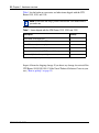
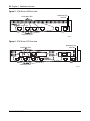
Figure 2, Figure 3 on page 24, and Figure 4 on page 24 show the front views of
the VPN Router 1010, the VPN Router 1050, and the VPN Router 1100,
respectively. For a description of the LEDs, see “Understanding the LEDs” on
page 27.
Figure 2 VPN Router 1010 front view
Boot/Ready LED
10/100 Mb/s LEDs
LAN 0
Alert LED
LAN 1
Console
VPN Router 1010
Link/Activity LEDs
10675EA
Nortel VPN Router Installation — VPN Router 1010/1050/1100
24 Chapter 1 Hardware overview
Figure 3 VPN Router 1050 front view
Boot/Ready LED
10/100 Mb/s LEDs
Alert LED
VPN Router 1050
A
B
C
D
LAN 1
Console
LAN 0
Link/Activity LEDs
10676EA
Figure 4 VPN Router 1100 front view
Boot/Ready LED
10/100 Mb/s LEDs
A
B
Alert LED
C
LAN 0
D
LAN 1
Console
VPN Router 1100
Link/Activity LEDs
10677EA
NN46110-313 02.01
Chapter 1 Hardware overview 25
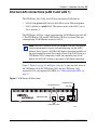
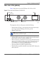
Rear view of the gateway
Figure 5 shows the rear view of the VPN Router 1010, 1050, and 1100.
Figure 5 Rear view of the VPN Router 1010/1050/1100
DC power supply
Label
On/Off switch
LAN0 Private MAC Address
LAN1 Public MAC Address
DC Input
19V/3.16 A
60W max.
1
Power
RC
0
Power LED
Recovery switch
Ground screw
10679EA
The components on the rear of the gateway include the following:
•
•
The port labeled “DC Input” is the receptacle for the external power supply
that is shipped with the VPN Router 1010, 1050, and 1100.
Mechanical on/off switch.
Note: Nortel recommends that you wait 5 seconds after you turn off the
gateway before you turn it on again.
•
•
•
•
The Power LED is green when power is supplied to the unit and the internal
power converters are not in a protective shutdown state.
The recessed recovery switch boots the recovery image. To boot the recovery
image, press the switch by inserting a paper clip into it during the power-on
self-test memory test. For more information about system recovery, see
Nortel VPN Router Troubleshooting (NN46110-602).
You use the ground screw (GND) to ground the chassis.
The label on the rear panel lists the media access control (MAC) addresses for
LAN 0 and LAN 1.
Nortel VPN Router Installation — VPN Router 1010/1050/1100
26 Chapter 1 Hardware overview
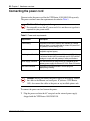
Connecting the power cord
You must order the power cord for the VPN Router 1010/1050/1100 separately.
The power cord must meet the requirements described in Table 2.
Caution: Risk of equipment damage
Do not modify or use the AC power cord if it is not the exact type that is
required for your power outlet.
Table 2 Power cord requirements
Requirement
Description
Current rating
The power cord must be rated for the available AC voltage
and must have a current rating that is at least 125 percent of
the gateway’s current rating (1.5 A).
Certification
The power cord must have certification marks from an
acceptable regional agency.
Cord length and flexibility The power cord must be less than 4.5 meters (14.7 feet) long.
It must be a flexible HAR (harmonized) cord or VDE-certified
cordage to comply with the gateway’s safety certifications.
Power supply connector
The connector that you plug into the AC receptacle on the
gateway power supply must be an IEC 320, Sheet C5 female.
Wall outlet connector
The power cord must terminate in a male plug with
appropriate grounding.
Caution: Before you connect the power supply to the gateway, connect
the cables to the Ethernet and serial ports. If you have a VPN Router
1100, also connect the cables to the ports on any installed option cards.
To connect the power cord and turn on the power:
1
NN46110-313 02.01
Plug the power cord into the AC receptacle on the external power supply
shipped with the VPN Router 1010/1050/1100.
Chapter 1 Hardware overview 27
2
Plug the power cord into the AC power outlet.
Caution: Risk of equipment damage
Protect the VPN Router 1010/1050/1100 by plugging it into a surge
suppressor.
3
Plug the external power supply into the port labeled “DC Input” on the back
of the gateway (Figure 5 on page 25).
4
Press the power switch to the “on” position and wait for the gateway to boot.
5
Verify a successful installation by checking the LEDs on the front panel (see
“Front panel LEDs” on page 27).
Note: For information about connecting the VPN Router 1010/1050/
1100 to the network, see Read Me First: Connecting for VPN Access
(314962-C).
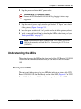
Understanding the LEDs
This section describes the LEDs on the front panel of the VPN Router 1010/1050/
1100 and on the communication cards that you can install in the VPN Router
1100.
Front panel LEDs
The front panel of the gateway has two LEDs that indicate the status of the VPN
Router 1010/1050/1100: the Boot/Ready and the Alert LEDs (Figure 6). The VPN
Router 1100 also has an audible alarm that corresponds to the Alert LED.
Nortel VPN Router Installation — VPN Router 1010/1050/1100
28 Chapter 1 Hardware overview
Figure 6 Front panel of the VPN Router 1010
Boot/Ready LED
10/100 Mb/s LEDs
LAN 0
Alert LED
LAN 1
Console
VPN Router 1010
Link/Activity LEDs
10675EA
Table 3 describes the LEDs on the VPN Router 1010/1050/1100 front panel.
Table 3 Front panel LED indicators
LED
Indicator
Description
Boot/Ready
Yellow
The gateway is booting and is in a non-ready state.
Green
The boot process is complete and the gateway is in a
state of readiness.
Yellow (on)
An alarm condition exists. The alarm may indicate a
serious condition, such as a hardware defect, or a
software attention condition. The alarm condition is
described in the health check display.
Off
No alarm condition exists.
Alert
For complete information about the health check, see Nortel VPN Router
Troubleshooting (NN46110-602).
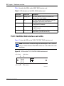
Ethernet port LEDs
To confirm that you cabled the Ethernet LAN interface properly, examine the port
LEDs on the front of the gateway. (Figure 6 on page 28 shows the LAN 0 and
LAN 1 port LEDs on the front of the VPN Router 1010.)
NN46110-313 02.01
Chapter 1 Hardware overview 29
Table 4 describes the Ethernet port LEDs on the VPN Router 1010/1050/1100.
Table 4 Ethernet port LED indicators
LED
Indicator
Description
10/100 Mb/s
(Amber)
On
The LAN port is operating at 100 Mb/s.
Off
The LAN port is operating at 10 Mb/s.
Link/Act
(Green)
On
The cable connections between the LAN port and the
hub are good.
Off
The cable connections between the LAN port and the
hub are faulty.
Flashing
The LAN port is sending or receiving network data.
The frequency of the flashes increases with
increased traffic.
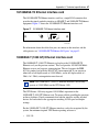
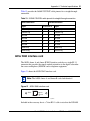
10/100BASE-TX Ethernet interface card LEDs
Figure 7 shows the LEDs on the 10/100BASE-TX Ethernet interface card.
100TX
Activity/Link
10/100Mbs
DATA
ACT/LINK
Figure 7 LEDs on the 10/100BASE-TX Ethernet interface card
CS260009B
Table 5 describes the LEDs on the 10/100BASE-TX Ethernet interface card.
Table 5 LED indicators on the 10/100BASE-TX Ethernet interface card
LED
Indicator
Description
ACT/LINK
Steady green or
Flashing green
The card is sending or receiving network data. The
frequency of the flashes increases with increased
traffic.
Off
The card is not sending or receiving data.
Green
The port is operating at 100 Mb/s.
Off
The port is operating at 10 Mb/s.
10/100TX
Nortel VPN Router Installation — VPN Router 1010/1050/1100
30 Chapter 1 Hardware overview
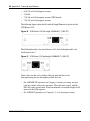
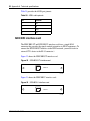
1000BASE-T (1000 GT) Ethernet interface card LEDs
The following figures show the LEDs on the 1000BASE-T (1000 GT) Ethernet
interface card. Although the card supports 10/100/1000 Mbit/s operation, the VPN
Router 1100 only supports 10/100 Mbit/s operation.
Figure 8 LEDs on the full-height 1000BASE-T (1000 GT) Ethernet interface card
Figure 9 LEDs on the half-height 1000BASE-T (1000 GT) Ethernet card
The following table describes the LEDs on the 1000BASE-T (1000 GT) Ethernet
interface card.
Table 6 LED indicators on the 1000BASE-T (1000 GT) Ethernet interface card
LED
Indicator
Description
ACT/LINK
Steady green
The port is connected to a valid link partner.
Flashing green
The card is sending or receiving network data. The
frequency of the flashes increases with increased
traffic.
Off
The card is not sending or receiving data.
Green
The port is operating at 100 Mb/s.
Off
The port is operating at 10 Mb/s.
10/100TX
NN46110-313 02.01
Chapter 1 Hardware overview 31
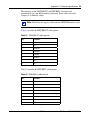
56/64K CSU/DSU WAN interface card LEDs
Figure 10 shows the LEDs on the 56/64K CSU/DSU WAN interface card.
Figure 10 LEDs on the 56/64K CSU/DSU WAN interface card
Blue LED
Red LED
56/64K
DDS
Green LED
Yellow LED
Table 7 describes the LEDs on the 56/64K CSU/DSU WAN interface card.
Table 7 LED indicators on the 56/64K CSU/DSU WAN interface card
LED
Description
Blue
The blue alarm LED is lit when receiving an upstream failure
denoted by an alarm indication signal (AIS).
Red
The red alarm LED is lit when a loss-of-signal (LOS) or
out-of-frame (OOF) condition is detected on the receive signal.
Yellow
The yellow alarm LED is lit when the far-end equipment is in the
red alarm condition.
Green
The green LED is lit when the condition is normal operation.
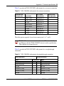
ADSL WAN interface card LEDs
Figure 11 shows the LEDs on the ADSL WAN interface card.
Figure 11 LEDs on the ADSL WAN interface card
RX/TX LED
RX/TX
ADSL
CONN
CONN LED
Nortel VPN Router Installation — VPN Router 1010/1050/1100
32 Chapter 1 Hardware overview
Table 8 describes the LEDs on the ADSL WAN interface card.
Table 8 LED indicators on the ADSL WAN interface card
CONN LED
Tx/Rx LED
Description
Steady green
Steady green
The ADSL interface card is not initialized; the
software driver is not installed.
Off
Off
The ADSL interface card is initialized, but has not
established a link with the ADSL network.
Flashing green
Off
The ADSL interface card is attempting to establish a
link with the ADSL network.
Steady green
Off
The ADSL interface card has established a link with
the ADSL network.
Steady green
Flashing green
The ADSL interface card is sending or receiving
network data. (The LED can be dim.)
T1/E1 CSU/DSU WAN interface card LEDs
Figure 12 shows the LEDs on the T1/E1 CSU/DSU WAN interface card.
Note: The brackets of the full-height and half-height T1/E1 CSU/DSU
cards are almost identical. The LEDs on the two cards indicate the same
conditions.
Figure 12 LEDs on the T1/E1 CSU/DSU WAN interface card
LED 1, Red
LED 2, Blue
LED 4, Green
LED 3, Yellow
CS160012A
NN46110-313 02.01
Chapter 1 Hardware overview 33
Table 9 describes the LEDs on the T1/E1 CSU/DSU WAN interface card.
Table 9 LED indicators on the T1/E1 CSU/DSU WAN interface card
LED
Indicator
Description
LED 1
Red
The red alarm LED is lit when a loss-of-signal (LOS) or
out-of-frame (OOF) condition is detected on the receive
signal.
LED 2
Blue
The blue alarm LED is lit when receiving an upstream
failure denoted by an alarm indication signal (AIS).
LED 3
Yellow
The yellow alarm LED is lit when the far-end equipment
is in the red alarm condition.
LED 4
Green
The green LED is lit when the condition is normal
operation.
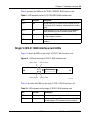
Single V.35/X.21 WAN interface card LEDs
Figure 13 shows the LEDs on the single V.35/X.21 WAN interface card.
Figure 13 LEDs on the single V.35/X.21 WAN interface card
LED 1, Red
LED 2, Green
LED 4, Green
LED 3, Green
CS160011A
Table 10 describes the LEDs on the single V.35/X.21 WAN interface card.
Table 10 LED indicators on the single V.35/X.21 WAN interface card
LED
Indicator
Description
LED 1
Red
No external transmit clock source is available.
LED 2
Green
The signals CDC and DSR are on between the DSU
and the adapter. LED 2 detects receive link status.
Nortel VPN Router Installation — VPN Router 1010/1050/1100
34 Chapter 1 Hardware overview
Table 10 LED indicators on the single V.35/X.21 WAN interface card
LED 3
Green
Power to the adapter is on and the onboard
microcode is loaded.
LED 4
Green
Cable is detected.
NN46110-313 02.01
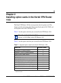
35
Chapter 2
Installing option cards in the Nortel VPN Router
1100
The Nortel VPN Router 1100 has two expansion slots for option cards. This
chapter provides instructions about how to install and replace LAN, WAN, and
serial option cards in the VPN Router 1100.
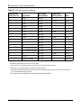
Table 11 lists the option cards that you can install in the VPN Router 1100..
Note: The 1000BASE-T (1000 GT) Ethernet interface card only
operates at 10/100 Mbit/s on the VPN Router 1100.
Table 11 lists the option cards that you can install in the VPN Router 1100.
Table 11 Supported option cards for the Nortel VPN Router 1100
Option card
Maximum number1
10/100BASE-TX Ethernet interface
2
1000BASE-T (1000 GT) Ethernet interface2
2
56/64K CSU/DSU WAN interface3
2
ADSL WAN interface
2
ISDN BRI S/T or U interface5
1
T1/E1 CSU/DSU WAN interface (half-height)
2
T1 CSU/DSU WAN interface (full-height)
1
Single V.35/X.21 WAN interface (half-height)6
2
Single V.35/X.21 WAN interface (full-height)
1
V.90 modem interface
1
4
7
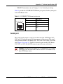
1 When only one card of a type is supported, you must install that card in the larger
slot, that is, slot 2.
Nortel VPN Router Installation — VPN Router 1010/1050/1100
36 Chapter 2 Installing option cards in the Nortel VPN Router 1100
2 The VPN Router 1100 must be running Version 5.05.330, 6.05.140 and later,
7.00.062, 7.05.100 and later, or 7.05.300 and later. The VPN Router 1100 supports
10/100 Mbps operation only.
3 The VPN Router 1100 must be running Version 5.0 or later.
4 The VPN Router 1100 must be running Version 4.90 or later.
5 The VPN Router 1100 must be running Version 4.80 or later.
6 The VPN Router 1100 must be running Version 4.80 or later.
7 The VPN Router 1100 must be running Version 4.80 or later.
To install a new LAN, WAN, or serial option card:
1
Use the Web GUI or the command line interface to shut down the gateway.
•
•
Web GUI: Choose Admin > Shutdown. Select the option to power off the
gateway after shutdown.
Command line interface: Use the reload command to shut down the
system. For example, enter reload power-off disable-logins
“Upgrade hardware” (for the complete syntax of the reload
command, see Nortel VPN Router Using the Command Line Interface.
2
Wait for the system to shut down.
3
Turn off the VPN Router 1100 power.
The power switch and power outlet are on the rear of the VPN Router 1100.
4
Disconnect the power cord from the power outlet and then disconnect the cord
from the VPN Router 1100.
Warning: Risk of electric shock
Make sure to turn off the VPN Router 1100 and unplug it before you
attempt to remove or install an option card.
5
Remove the cables attached to the ports of the VPN Router 1100.
6
If there are option cards currently installed, unscrew the two screws on each
bracket and remove the bracket.
Caution: Risk of equipment damage
Unscrew the option card brackets before you remove the cover from the
VPN Router 1100, or you will damage the option cards.
NN46110-313 02.01
Chapter 2 Installing option cards in the Nortel VPN Router 1100 37
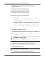
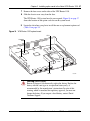
7
Remove the four screws on the sides of the VPN Router 1100.
8
Slide the chassis cover away from the base.
The VPN Router 1100 system board is now exposed. Figure 14 on page 37
shows the location of the option card slots on the system board.
9
Locate the slot where you plan to install the new or replacement option card
(Table 11 on page 35).
Figure 14 VPN Router 1100 system board
CPU
Compact
flash
DIMM
Option card
slots
Slot 3
Slot 2
10678FA
Warning: Risk of injury
Beware of danger if you incorrectly replace the battery. Replace the
battery with the same type or an equivalent battery only, as
recommended by the manufacturer’s instructions. In spite of this
warning, which is mandated for regulatory approval, you must not
change the battery. If you suspect a dead battery, contact Nortel
Customer Support.
Nortel VPN Router Installation — VPN Router 1010/1050/1100
38 Chapter 2 Installing option cards in the Nortel VPN Router 1100
10 Attach an antistatic wrist strap (not included with the VPN Router 1100
shipment).
Caution: Risk of equipment damage
Electrostatic discharge can damage VPN Router 1100 components.
11 Remove the blank card bracket (or the option card that you are replacing)
from the slot.
Caution: Risk of equipment damage
If you must remove an ADSL option card from slot 3 (Figure 14 on
page 37), lift the free end of the card so that the card is at a slight angle,
and then carefully pull it up and out of the slot so that the card clears the
connector of the adjacent slot 2. If you damage components on the
underside of the ADSL interface card, the card does not work.
12 Install the new option card.
Caution: Risk of equipment damage
To prevent stress damage to components on the underside of the ADSL
option card when you install that card in slot 3 (Figure 14 on page 37),
hold the card at a slight angle and insert it into the connector so that the
card clears the connector of the adjacent slot 2. If you damage
components on the underside of the ADSL interface card, the card does
not work.
Press the card all the way into the PCI connector on the motherboard.
13 Carefully slide the chassis cover onto the base, and secure it with the four
screws.
14 Attach the bracket of the new option card to the front panel with two screws.
15 Connect the cables to the system ports and to the option card ports.
16 Plug the power cord into the AC power outlet.
17 Plug the external power supply into the port labeled DC Input on the back of
the VPN Router 1100.
NN46110-313 02.01
Chapter 2 Installing option cards in the Nortel VPN Router 1100 39
18 Press the power switch to the on position and wait for the gateway to boot.
Caution: The boot process can take as long as 3 minutes. Do not turn
the power off and on again; recycling the power quickly can cause
problems. Always wait at least 5 seconds, after you turn off the power,
before you turn it on again.
Nortel VPN Router Installation — VPN Router 1010/1050/1100
40 Chapter 2 Installing option cards in the Nortel VPN Router 1100
NN46110-313 02.01
41
Appendix A
Technical specifications
This appendix provides technical specifications for the VPN Router 1010, 1050,
and 1100 chassis and for their interfaces.
Chassis specifications
Table 12 lists the physical specifications for the VPN Router 1010, 1050, and
1100 chassis.
Table 12 Physical specifications
Chassis
Height
Width
Depth
Weight
VPN Router 1010
1.75 in. (4.44 cm)
8.25 in. (21 cm)
7.5 in. (19 cm)
2.65 lb (1.2 kg)
VPN Router 1050
1.75 in. (4.44 cm)
8.25 in. (21 cm)
7.5 in. (19 cm)
2.75 lb (1.25 kg)
VPN Router 1100
1.75 in. (4.44 cm)
8.25 in. (21 cm)
10.75 in. (27.3 cm)
3.8 lb (1.7 kg)
Table 13 lists the electrical and environmental specifications for the chassis.
Table 13 Electrical and environmental specifications
Specification
Description
Electrical
Voltage
100–240 VAC
Current
1.5 A
Frequency
50–60 Hz
Operating environment
Temperature
32–104oF (0–40oC)
Relative humidity
10–90% noncondensing
Nortel VPN Router Installation — VPN Router 1010/1050/1100
42 Appendix A Technical specifications
System ports
The VPN Router 1010/1050/1100 system board provides the following interfaces:
•
•
10/100BASE-TX Ethernet LAN ports
Serial port
This section provides information about the 10/100BASE-TX Ethernet LAN ports
and the serial port on the system board.
10/100BASE-TX Ethernet LAN ports
The VPN Router 1010, 1050, and 1100 have two internal LANs built in:
•
•
LAN 0 is the private LAN and also the LAN to use for Web management.
— The LAN 0 connector on the front of the VPN Router 1010 is an Ethernet
MDI configuration and requires a crossover cable (included with your
shipment).
— The LAN 0 connectors on the front of the VPN Router 1050 and 1100 are
an Ethernet medium dependent interface crossover (MDI-X)
configuration. These ports support the Auto-MDI-X feature, so either
straight-through or crossover cables can be used.
LAN 1 defaults to a public LAN. The software refers to the LAN 1 port as slot
1, interface 1.
The LAN 1 connector on the front of the VPN Router 1010, 1050, and 1100 is an
Ethernet MDI configuration and requires an RJ-45 straight-through cable.
Depending on whether you use the interface for 10BASE-T or 100BASE-TX
operation, select cables for the interfaces as follows:
•
100BASE-TX connections require Category 5 twisted-pair wire. The
100BASE-TX specification supports 100 Mb/s transmission over two pairs of
Category 5 twisted-pair Ethernet wiring: one pair each for transmit and
receive operations.
Nortel recommends a maximum length of 100 meters for the cable segment
between a 100BASE-TX repeater and a workstation (due to signal timing
requirements). This wiring scheme complies with the EIA 568 wiring
standard.
NN46110-313 02.01
Appendix A Technical specifications 43
•
10BASE-T connections can use Category 3, 4, or 5 twisted-pair wiring.
Table 14 provides the 10/100BASE-TX Ethernet port pinouts for the system ports
on the VPN Router 1100.
Table 14 10/100BASE-TX Ethernet port pinouts
TX+ TX- RX+ RX12345678
Pin
Description
1
TX +
2
TX -
3
RX +
6
RX -
CS260010A
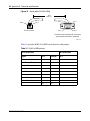
Serial port
The system board provides a serial port on the front of the VPN Router 1010,
1050, and 1100 to enable out-of-band management of the gateway. The serial
cable provided with the VPN Router 1010, 1050, and 1100 is an RJ-45-to-DB9
cable (Figure 15 on page 44). The RJ-45 connector goes into the VPN Router
1010, 1050, or 1100, and the DB9 connector goes into your workstation.
Caution: Use this cable to connect a PC or modem to the VPN Router
1010/1050/1100. Do not use this cable to attach a PC or modem to any
other VPN Router device.
Nortel VPN Router Installation — VPN Router 1010/1050/1100
44 Appendix A Technical specifications
Figure 15 Serial cable (RJ-45-to-DB9)
10 ft
(3.05 m)
Pin 8
Pin 1
RJ-45 connector
Pin 5
Pin 1
Pin 9
Pin 6
9-position D-sub receptacle with screw locks
(ground shield connected to backshell)
CAB0110A
Table 15 provides the RJ-45-to-DB9 serial interface cable pinouts.
Table 15 RJ-45 to DB9 pinouts
RJ-45 termination
DB-9 termination
Signal
Pin #
Direction
Pin #
Request to Send
1
8
Data Terminal Ready
2
Receive Data
3
Not Connected
4
Send Data
5
Gnd
6
Data Set Ready
7
Clear to Send
8
--->
--->
<--<--->
--->
<--->
<--<---
N/A
N/C
9
NN46110-313 02.01
6
3
1
2
5
4
7
Appendix A Technical specifications 45
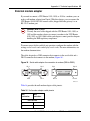
External modem adapter
If you need to connect a VPN Router 1010, 1050, or 1100 to a modem, you can
order a null modem adapter from Nortel. With this adapter, you can connect the
VPN Router 1010/1050/1100 console cable (shipped with the gateway) to an
RS-232-C modem port.
Caution: Risk of EMI
Use only the serial cable shipped with the VPN Router 1010, 1050, or
1100 and this modem adapter to connect a modem to the VPN Router
1010, 1050, or 1100. Other cables and adapters cannot provide adequate
shielding for EMI regulatory compliance.
To ensure correct dial-in and dial-out operation, configure the modem with the
settings verbal result codes and display result codes. For more information, see
the modem documentation.
The cable adapter has a DB9 connector that connects to the serial cable and a
DB-25 connector that connects to the modem (Figure 16).
Figure 16 Serial cable adapter for connection to modem (DB9-to-DB25)
Pin 1
Pin 5
Pin 6
Pin 9
Pin 1
Pin 14
Pin 13
Pin 25
CAB0113A
Table 16 provides the null modem adapter cable pinouts.
Table 16 Null modem adapter cable pinouts
DB9
termination
DB25
termination
Pin # to Pin #
2
2
3
3
Nortel VPN Router Installation — VPN Router 1010/1050/1100
46 Appendix A Technical specifications
Table 16 Null modem adapter cable pinouts (continued)
DB9
termination
DB25
termination
Pin # to Pin #
4
6
5
7
6
20
7
5
8
4
Hardware option cards
The VPN Router 1100 has two expansion slots that support a combination of the
following network interface cards:
•
•
•
•
•
•
•
•
•
10/100BASE-TX Ethernet
10/100/1000BASE-X Ethernet
56/64K CSU/DSU WAN
ADSL WAN
ISDN BRI
T1/E1 CSU/DSU WAN (half-height card)
T1 CSU/DSU WAN (full-height card)
V.90 modem
Single V.35/X.21 WAN
This section provides information about the connectors and cable pinouts for each
supported interface card. For instructions about installing an option card, see
Chapter 2, “Installing option cards in the Nortel VPN Router 600 1100,” on page
35.
NN46110-313 02.01
Appendix A Technical specifications 47
10/100BASE-TX Ethernet interface card
The 10/100BASE-TX Ethernet interface card has a single RJ-45 connector that
provides the signals needed to interface to 10BASE-T and 100BASE-TX Ethernet
equipment. Figure 17 shows the 10/100BASE-TX Ethernet interface card.
100TX
ACT/LINK
DATA
Figure 17 10/100BASE-TX Ethernet interface card
CS260009B
For information about the cables that you can connect to this interface and the
cable pinouts, see “10/100BASE-TX Ethernet LAN ports” on page 42.
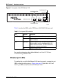
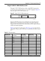
1000BASE-T (1000 GT) Ethernet interface card
The 1000BASE-T (1000 GT) Ethernet card replaces the 10/100BASE-TX
Ethernet card (see the previous section). This card provides 10/100/1000 Mbit/s
Ethernet services and supports autonegotiation. The card supports the IEEE
802.3ab standard and provides RJ-45/CAT 5 interconnection. It can operate in
either full or half duplex mode at 10/100 Mbit/s, and in full duplex mode at 1
Gbit/s. At 1 Gbit/s, autonegotiation must be used.
Note: The 1000BASE-T (1000 GT) Ethernet interface card can only
operate at 10/100 Mbit/s on the VPN Router 1100.
The VPN Router 1100 only supports 10/100 Mbit/s operation for the
1000BASE-T (1000 GT) Ethernet card. To ensure reliable speed/duplex operation
on these platforms, Nortel recommends that both the interface and the attached
devices are hard-coded to the appropriate matching 10/100 speed and duplex
settings.
For the 1000BASE-T (1000 GT) Ethernet interface card to be recognized by the
system, the minimum required VPN Router operating software is:
•
5.05.330
Nortel VPN Router Installation — VPN Router 1010/1050/1100
48 Appendix A Technical specifications
•
•
•
•
6.05.140 and all subsequent versions
7.00.062
7.05.100 and all subsequent versions (FIPS branch)
7.05.300 and all subsequent versions
The following figures show the full and half-height Ethernet faceplates for the
VPN Router 1100.
Figure 18 VPN Router 1100 full-height 1000BASE-T (1000 GT)
The full-height model is for installation in slot 2; the half-height model is for
installation in slot 3.
Figure 19 VPN Router 1100 half-height 1000BASE-T (1000 GT)
Select cables for this card as follows. Keep in mind that this card is
auto-negotiating and uses the highest possible data rate:
•
•
NN46110-313 02.01
For 100BASE-TX operation, use Category 5 twisted-pair wiring: one pair
each for transmit and receive operations. The cable must comply with the
EIA 568 wiring specification. Nortel recommends a maximum length of 100
meters for the cable segment.
For 10BASE-T operation, use Category 3, 4, or 5 twisted-pair wiring.
Appendix A Technical specifications 49
The following table provides the pinouts for the 1000BASE-T (1000 GT) Ethernet
interface card..
Table 17 1000BASE-T (1000 GT) Ethernet pinouts
12345678
CS260010A
Pin
Description
1
TP0+
2
TP0-
3
TP1+
4
TP2+
5
TP2-
6
TP1-
7
TP3+
8
TP3-
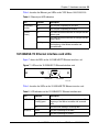
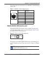
56/64K CSU/DSU WAN interface card
The 56/64K CSU/DSU WAN interface card has a single RJ-48 connector that
provides the signals needed to interface to network equipment. Figure 20 shows
the 56/64K CSU/DSU WAN interface card.
Figure 20 56/64K CSU/DSU WAN interface card
56/64K
DDS
10972EA
The connector on the 56/64K CSU/DSU WAN interface card accommodates an
8-pin RJ-48 modular patch cord. These cables are sold as Category 5, or Ethernet,
cables.
Note: Nortel does not supply an interface cable with the
56/64K CSU/DSU WAN interface card.
Nortel VPN Router Installation — VPN Router 1010/1050/1100
50 Appendix A Technical specifications
Use cable that is wired in accordance with EIA-568-A wiring style. This wiring
style ensures that a twisted pair inside the patch cord carries the transmit signal
(pins 1 and 2) and the receive signal (pins 7 and 8). Nortel strongly recommends
that you use factory-made patch cords.
You connect the 56/64K CSU/DSU WAN interface card to the service provider
network using a straight-through cable or a crossover cable, depending on how the
service provider wired its jack.
•
•
For a straight-through connection, you can use a standard Category 5
(Ethernet) straight-through cable.
For a crossover connection, you cannot use a standard Category 5 crossover
cable. Do not interchange the 56/64K CSU/DSU crossover cable and the
Ethernet crossover cable.
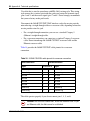
Table 18 provides the 56/64K CSU/DSU cable pinouts for a crossover
connection.
Table 18 56/64K CSU/DSU cable pinouts for crossover connection
Nortel termination
Remote termination
Signal
Pin # to Pin #
Signal
Transmit tip
1
7
Receive tip
Transmit ring
2
8
Receive ring
not used
3
3
not used
not used
4
4
not used
not used
5
5
not used
not used
6
6
not used
Receive tip
7
1
Transmit tip
Receive ring
8
2
Transmit ring
The cable operates properly if you do not connect pins 3, 4, 5, and 6.
Caution: For crossover connections, do not use Ethernet cable. If you
use Ethernet cable, the link cannot be established.
NN46110-313 02.01
Appendix A Technical specifications 51
Table 19 provides the 56/64K CSU/DSU cable pinouts for a straight-through
connection.
Table 19 56/64K CSU/DSU cable pinouts for straight-through connection
Nortel termination
Remote termination
Signal
Pin # to Pin #
Signal
Transmit tip
1
1
Transmit tip
Transmit ring
2
2
Transmit ring
not used
3
3
not used
not used
4
4
not used
not used
5
5
not used
not used
6
6
not used
Receive tip
7
7
Receive tip
Receive ring
8
8
Receive ring
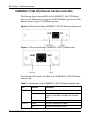
ADSL WAN interface card
The ADSL Annex A and Annex B WAN interface cards have a single RJ-11
connector that provides the signals needed to interface to the digital subscriber
line access multiplexer (DSLAM) and to telephone equipment.
Figure 21 shows the ADSL WAN interface card.
Note: The ADSL Annex A and Annex B cards look identical.
Figure 21 ADSL WAN interface card
ADSL
Tx/Rx
CONN
10972EA
Included in the accessory box is a 7-foot RJ-11 cable to attach to the DSLAM.
Nortel VPN Router Installation — VPN Router 1010/1050/1100
52 Appendix A Technical specifications
Table 20 provides the ADSL port pinouts.
Table 20 ADSL cable pinouts
Pin
Function
1
N/C
2
Tip
3
Ring
4
N/C
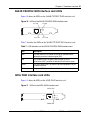
ISDN BRI interface card
The ISDN BRI S/T and ISDN BRI U interface cards have a single RJ-45
connector that provides the signals needed to interface to ISDN equipment. (To
connect the ISDN BRI S/T interface to the ISDN network, you must attach an
external NT-1 device to the RJ-45 connector.)
Figure 22 shows the ISDN BRI S/T interface card.
Figure 22 ISDN BRI S/T interface card
ISDN-ST
10972EA
Figure 23 shows the ISDN BRI U interface card.
Figure 23 ISDN BRI U interface card
ISDN-U
10972EB
NN46110-313 02.01
Appendix A Technical specifications 53
The connector on the ISDN BRI S/T and ISDN BRI U interface cards
accommodates an 8-pin RJ-45 modular patch cord. These cables are sold as
Category 5, or Ethernet, cables.
Note: Nortel does not supply a cable with the ISDN BRI interface cards.
Table 21 provides the ISDN BRI S/T cable pinouts.
Table 21 ISDN BRI S/T cable pinouts
Pin
Function
1
N/C
2
N/C
3
Receive +
4
Transmit +
5
Transmit -
6
Receive -
7
N/C
8
N/C
Table 22 provides the ISDN BRI U cable pinouts.
Table 22 ISDN BRI U cable pinouts
Pin
Function
1
N/C
2
N/C
3
N/C
4
U interface network connection (tip)
5
U interface network connection (ring)
6
N/C
7
N/C
8
N/C
Nortel VPN Router Installation — VPN Router 1010/1050/1100
54 Appendix A Technical specifications
T1/E1 CSU/DSU WAN interface card
The T1/E1 CSU/DSU WAN interface card has a single connector that provides
the signals needed to interface to T1 or E1 equipment. Figure 24 shows the T1/E1
CSU/DSU WAN interface card. This interface card ships as a half-height card and
as a full-height card.
Figure 24 T1/E1 CSU/DSU WAN interface card
CS160012A
Note: The brackets of the half-height and full-height cards are almost
identical. For E1 service, you must install the half-height version of the
T1/E1 CSU/DSU WAN interface card.
The connector on the T1/E1 CSU/DSU WAN interface card accommodates an
8-pin RJ-48 modular patch cord. These cables are sold as Category 5, or Ethernet,
cables. Nortel does not supply an interface cable with the T1/E1 CSU/DSU WAN
interface card.
Use cable that is wired in accordance with EIA-568-A wiring style. This wiring
style ensures that a twisted pair inside the patch cord carries the transmit signal
(pins 4 and 5) and the receive signal (pins 1 and 2). Nortel strongly recommends
that you use factory-made patch cords.
You connect the T1/E1 CSU/DSU WAN interface card to the service provider
network using a straight-through cable or a crossover cable, depending on how the
service provider wired its jack.
•
•
NN46110-313 02.01
For a straight-through connection, you can use a standard Category 5
(Ethernet) straight-through cable.
For a crossover connection, you cannot use a standard Category 5 crossover
cable. Do not interchange the T1/E1 CSU/DSU crossover cable and the
Ethernet crossover cable.
Appendix A Technical specifications 55
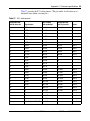
Table 23 provides the T1/E1 CSU/DSU cable pinouts for a crossover connection.
Table 23 T1/E1 CSU/DSU cable pinouts for crossover connection
Standard-wired
end 8-pin male
Signal name
Pair number
and conductor
Special-wired
end 8-pin male
1
RXDA<-TXDA
wht/org pair 2A
5
2
RXDB<-TXDB
orange pair 2B
4
3
not used
wht/grn pair 3A
3
4
TXDB->RXDB
blue pair 1B
2
5
TXDA->RXDA
wht/blu pair 1A
1
6
not used
green pair 3B
6
7
not used
wht/brn pair 4A
7
8
not used
brown pair 4B
8
The cable operates properly if you do not connect pins 3, 6, 7, and 8.
Caution: For crossover connections, do not use Ethernet cable. If you
use Ethernet cable the T1/E1 CSU/DSU does not work to specifications.
This condition can corrupt the data.
Table 24 provides the T1/E1 CSU/DSU cable pinouts for a straight-through
connection.
Table 24 T1/E1 CSU/DSU cable pinouts for straight-through connection
Nortel termination
Remote termination
Signal
Pin # to Pin #
Signal
Receive A (RXDA)
1
1
Receive A (RXDA)
Receive B (RXDB)
2
2
Receive B (RXDB)
not used
3
3
not used
Transmit B (TXDB)
4
4
Transmit B (TXDB)
Transmit A (TXDA)
5
5
Transmit A (TXDA)
not used
6
6
not used
Nortel VPN Router Installation — VPN Router 1010/1050/1100
56 Appendix A Technical specifications
Table 24 T1/E1 CSU/DSU cable pinouts for straight-through connection
Nortel termination
Remote termination
not used
7
7
not used
not used
8
8
not used
V.90 modem interface card
The V.90 modem interface card has two RJ-11 connectors that provide the signals
needed to interface to an incoming telephone line and to telephone equipment.
Figure 25 shows the V.90 modem interface card.
LINE
PHONE
Figure 25 V.90 modem interface card
10973EA
Included in the accessory box is a 7-foot RJ-11 cable to attach to a telephone jack.
Table 25 provides the V.90 modem port cable pinouts.
Table 25 V.90 modem cable pinouts
Pin
Function
1
N/C
2
Tip
3
Ring
4
N/C
NN46110-313 02.01
Appendix A Technical specifications 57
Single V.35/X.21 WAN interface card
The single V.35/X.21 WAN interface card has a single DB28S connector that
provides the signals needed to interface to V.35 and X.21 equipment. Figure 26
shows the single V.35/X.21 WAN interface card.
Figure 26 Single V.35/X.21 WAN interface card
CS160011A
You need a DSU/CSU (digital service unit/channel service unit) between the
WAN connection and the gateway. You can order a V.35 or X.21 cable from
Nortel to attach to the connector. This cable enables the WAN adapter to function
as DTE (data terminal equipment).
Table 26 provides the V.35 cable pinouts. Table 27 on page 59 provides the X.21
cable pinouts. (The pair suffix A or B refers to an individual wire within a twisted
pair.)
Table 26 V.35 cable pinouts
Standard-wired
end 28-pin male
Signal name
Pair number
and conductor
Special-wired
end 34-pin male
2
TXDA
pair 1A
P
14
TXDB
pair 1B
S
3
RXDA
pair 2A
R
16
RXDB
pair 2B
T
15
TXCA
pair 3A
Y
12
TXCB
pair 3B
AA
17
RXCA
pair 4A
V
9
RXCB
pair 4B
X
24
SCTEA
pair 5A
U
11
SCTEB
pair 5B
W
4
RTSA
pair 6A
C
19
RTSB
pair 6B
no conn
Notes
Note 1
Nortel VPN Router Installation — VPN Router 1010/1050/1100
58 Appendix A Technical specifications
Table 26 V.35 cable pinouts (continued)
Standard-wired
end 28-pin male
Signal name
Pair number
and conductor
Special-wired
end 34-pin male
5
CTSA
pair 7A
D
13
CTSB
pair 7B
no conn
6
DSRA
pair 8A
E
22
DSRB
pair 8B
J
20
DTRA
pair 9A
H
23
DTRB
pair 9B
no conn
8
DCDA
pair 10A
F
10
DCDB
pair 10B
no conn
18
LL
pair 11A
L
21
RL
pair 11B
N
25
TM
pair 12A
NN
26
M0<-SIGNAL GROUND
pair 12B
B
Note 2
27
M1<-SIGNAL GROUND
pair 13A
B
Note 2
28
M2
pair 13B
no conn
Note 1
1
SHIELD
pair 14A
A
Notes 3,4
7
SIGNAL GROUND
pair 14B
B
Notes 2,4
Notes
Note 1
Note 1
Note 1
The following notes apply to the single V.35 DTE cable:
1. The term “no conn” means the wire is not connected to a pin in the 34-pin connector.
2. Wires 12B, 13A, and 14B connect to pin B in the 34-pin connector.
3. At each end, the cable shield and connector shell must connect respectively to pin A of the 34-pin connector and
pin 1 of the standard 28-pin connector.
4. Do not connect Shield to Signal Ground because these are separate signals.
NN46110-313 02.01
Appendix A Technical specifications 59
Table 27 provides the X.21 cable pinouts. (The pair suffix A or B refers to an
individual wire within a twisted pair.)
Table 27 X.21 cable pinouts
Standard-wired
end 28-pin male
Signal name
Pair number
and conductor
Standard-wired
end 15-pin male
2
TXDA
pair 1A
2
14
TXDB
pair 1B
9
3
RXDA
pair 2A
4
16
RXDB
pair 2B
11
15
TXCA
pair 3A
6
12
TXCB
pair 3B
13
17
RXCA
pair 4A
pair 5A
Note 1
9
RXCB
pair 4B
pair 5B
Note 1
24
SCTEA
pair 5A
pair 4A
Note 1
11
SCTEB
pair 5B
pair 4B
Note 1
4
RTSA
pair 6A
3
19
RTSB
pair 6B
10
5
CTSA
pair 7A
5
13
CTSB
pair 7B
12
6
DSRA
pair 8A
no conn
Note 2
22
DSRB
pair 8B
no conn
Note 2
20
DTRA
pair 9A
no conn
Note 2
23
DTRB
pair 9B
no conn
Note 2
8
DCDA
pair 10A
no conn
Note 2
10
DCDB
pair 10B
no conn
Note 2
18
LL
pair 11A
no conn
Note 2
21
RL
pair 11B
no conn
Note 2
25
TM
pair 12A
no conn
Note 2
26
M0
pair 12B
no conn
Note 2
27
M1
pair 13A
no conn
Note 2
28
M2<-SIGNAL GROUND
pair 13B
8
Note 3
Notes
Nortel VPN Router Installation — VPN Router 1010/1050/1100
60 Appendix A Technical specifications
Table 27 X.21 cable pinouts (continued)
Standard-wired
end 28-pin male
Signal name
Pair number
and conductor
Standard-wired
end 15-pin male
Notes
1
SHIELD
pair 14A
1
Note 4,5
7
SIGNAL GROUND
pair 14B
8
Note 3,5
The following notes apply to the single X.21 cable:
1. Wires of pair 4 connect to wires of pair 5, but not to any pins in the DA-15.
2. The term “no conn” means the wire is not connected to a pin in the 15-pin connector.
3. Wires 13B and 14B connect to pin 8 in the 15-pin connector.
4. At each end, the cable shield and connector shell must connect to pin 1 of the connector.
5. Do not interconnect Shield to Signal Ground because these are separate signals.
NN46110-313 02.01
61
Index
Numerics
C
10/100BASE-TX Ethernet interface card
cable specifications 42
described 47
installing 35
LEDs 29
port pinouts 43
cable adapter for modem 45
10/100BASE-TX system LAN ports
cable specifications 43
connector 43
LEDs 28
1000BASE-T (1000 GT) Ethernet interface card 47
LEDs 30
56/64K CSU/DSU WAN interface card
cable pinouts 50
connector 49
described 49
installing 35
LEDs 31
A
AC power cord
connecting 26
ordering 22
requirements 26
acronyms 18
adapter, for connecting serial cable to a modem 45
ADSL WAN interface card
cable pinouts 52
connector 51
described 51
installing 35
LEDs 31
cables
connecting 26
power. See AC power cord
technical specifications
100BASE-TX connector 43
10BASE-T connector 43
56/64K CSU/DSU WAN interface 49
ADSL WAN interface 51
ISDN BRI interface 53
serial interface 43
single V.35/X.21 WAN interface 57
T1/E1 CSU/DSU WAN interface 54
V.90 modem interface 56
Category 5 wiring requirements 43
chassis specifications 41
connecting
cables 26
power cord 26
connectors
10/100BASE-TX Ethernet interface card 47
10/100BASE-TX system LAN ports 43
56/64K CSU/DSU WAN interface 49
ADSL WAN interface 51
ISDN BRI S/T interface 52
ISDN BRI U interface 52
single V.35/X.21 WAN interface card 57
T1/E1 CSU/DSU WAN interface card 54
V.90 modem interface 56
conventions, text 18
Nortel VPN Router Installation — VPN Router 1010/1050/1100
62 Index
D
L
DC input port 25
LAN interface card
connector 47
installing 35
LEDs 29
specifications 47
E
electrical specifications 41
environmental specifications 41
Ethernet MDI configuration 42
F
front panel LEDs 27
H
LAN interface cards
LEDs
1000BASE-T (1000 GT) Ethernet 30
LAN ports, system
cable specifications 43
connector 43
described 23
LEDs 28
help, How to get 15
LEDs
10/100BASE-TX Ethernet interface card 29
1000BASE-T (1000 GT) Ethernet interface card
30
56/64K CSU/DSU WAN interface card 31
ADSL WAN interface card 31
front panel 27
Power 25
single V.35/X.21 WAN interface card 33
system LAN port 28
T1/E1 CSU/DSU WAN interface card 32
I
M
installing option cards 35
interfaces, option card, technical specifications 46
MAC addresses, for VPN Router 1010/1050/1100
25
interfaces, system, technical specifications 42
modem, cable adapter for 45
hardware option cards
installing in VPN Router 1100 35
specifications 46
help
by Express Routing Code 16
by Nortel distributor 16
by phone 16
latest update on Web 15
Nortel Web site 15
ISDN BRI S/T interface card
cable pinouts 53
connector 52
installing 35
ISDN BRI U interface card
cable pinouts 53
connector 52
installing 35
NN46110-313 02.01
N
NT-1 device, required for ISDN BRI S/T 52
null modem adapter 45
O
option cards
installing in VPN Router 1100 35
specifications 46
Index 63
P
described 43
shipment contents 22
physical specifications 41
pinouts
10/100BASE-TX Ethernet interface 43
56/64K CSU/DSU WAN interface 50
ADSL WAN interface 52
ISDN BRI S/T interface 53
ISDN BRI U interface 53
null modem adapter 45
serial interface cable 44
single V.35 WAN interface 57
single X.21 WAN interface 59
T1/E1 CSU/DSU WAN interface 55
V.90 modem interface 56
plug, AC power, specifications 26
shutting down the VPN Router 1100 36
single V.35/X.21 WAN interface card
connector 57
installing in VPN Router 1100 35
LEDs 33
V.35 pinouts 57
X.21 pinouts 59
specifications
chassis 41
option cards 46
serial port 43
system ports 42
system LAN ports
cable specifications 43
connector 43
LEDs 28
power cord
connecting 26
ordering 22
requirements 26
system ports, specifications 42
Power LED 25
powering down the VPN Router 1100 36
T
publications
hard copy 20
related 19
T1/E1 CSU/DSU WAN interface card
cable pinouts 55
connector 54
installing in VPN Router 1100 35
LEDs 32
R
recovery switch, for VPN Router 1010/1050/1100
25
technical publications 20
technical specifications 41
text conventions 18
S
turning off the VPN Router 1100 36
serial cable adapter
cable pinouts 45
connectors 45
V
serial interface cards
installing in VPN Router 1100 35
specifications
ISDN BRI 52
V.90 modem 56
serial port
cable pinouts 44
V.90 modem interface card
cable pinouts 56
connectors 56
installing in VPN Router 1100 35
VPN Router 1010/1050/1100
built-in LANs 23
connecting power cord 26
DC Input port 25
Nortel VPN Router Installation — VPN Router 1010/1050/1100
64 Index
description 21
MAC addresses 25
Power LED 25
recovery switch 25
shipment contents 22
technical specifications 41
VPN Router 1100
installing option cards 35
removing cover from base 37
shutting down 36
technical specifications 41
W
WAN interface cards
installing in VPN Router 1100 35
LEDs
56/64K CSU/DSU 31
ADSL 31
single V.35/X.21 33
T1/E1 CSU/DSU 32
specifications
56/64K CSU/DSU 49
ADSL 51
single V.35/X.21 57
T1/E1 CSU/DSU 54
wiring requirements, Category 5 43
NN46110-313 02.01