1
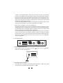
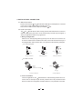
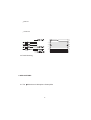
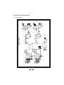
User's Manual
MICtube
STEREO TUBE PREAMP
www.altoproaudio.com
Version 2.3 September 2005
English
result in damage to the product and
possibly the user.
Unplug the product before electrical storms
occur and when unused for long periods of
time to reduce the risk of electric shock or
fire.
SAFETY RELATED SYMBOLS
CAUTION
RISK OF ELECTRIC SHOCK
DO NOT OPEN
This symbol, wherever used, alerts
you to the presence of un-insulated
and dangerous voltages within the
product enclosure. These are voltages
that may be sufficient to constitute the
risk of electric shock or death.
External Connection
Always use proper ready-made insulated
mains cabling (power cord). Failure to do
so could result in shock/death or fire. If
in doubt, seek advice, from a registered
electrician.
This symbol, wherever used, alerts
you to important operating and maintenance instructions. Please read.
Protective Ground Terminal
AC mains (Alternating Current)
Hazardous Live Terminal
Do not Remove any Covers
Within the product are areas where high
voltages may present. To reduce the risk
of electric shock do not remove any
covers unless the AC mains power cord
is removed.
Covers should be removed by qualified
service personnel only.
No user serviceable parts inside.
ON: Denotes the product is turned on.
OFF: Denotes the product is turned off.
WARNING
Describes precautions that should be
observed to prevent the possibility of
death or injury to the user.
Fuse
To prevent fire and damage to the
product, use only the recommended
fuse type as indicated in this manual.
Do not short-circuit the fuse holder.
Before replacing the fuse, make sure
that the product is OFF and disconnected
from the AC outlet.
CAUTION
Describes precautions that should be
observed to prevent damage to the
product.
Disposing of this product should
not be placed in municipal waste
and should be separate collection.
Protective Ground
Before turning the product ON, make sure
that it is connected to Ground. This is to
prevent the risk of electric shock.
Never cut internal or external Ground wires.
Likewise, never remove Ground wiring
from the Protective Ground Terminal.
WARNING
Power Supply
Ensure that the mains source voltage
(AC outlet) matches the voltage rating
of the product. Failure to do so could
1
Operating Conditions
Servicing
Always install in accordance with the
manufacturer's instructions.
To avoid the risk of electric shock and
damage, do not subject this product to
any liquid/rain or moisture. Do not use this
product when in close proximity to water.
Refer all servicing to qualified service
personnel only.
Do not perform any servicing other than
those instructions contained within the
User's Manual.
Do not install this product near any direct
heat source.
Do not block areas of ventilation. Failure
to do so could result in fire.
Keep product away from naked flames.
IMPORTANT SAFETY INSTRUCTIONS
Read these instructions
Follow all instructions
Keep these instructions. Do not discard.
Heed all warnings.
Only use attachments/accessories
specified by the manufacturer.
Power Cord and Plug
Do not tamper with the power cord or plug.
These are designed for your safety.
Do not remove Ground connections!
If the plug does not fit your AC outlet seek
advice from a qualified electrician.
Protect the power cord and plug from any
physical stress to avoid risk of electric shock.
Do not place heavy objects on the power
cord. This could cause electric shock or fire.
Cleaning
When required, either blow off dust from
the product or use a dry cloth.
Do not use any solvents such as Benzol
or Alcohol.
For safety, keep product clean and free
from dust.
2
Preface
Dear Customer,
Thanks for choosing LTO Stereo Tube Preamplifier and thanks for choosing one of
the results of
LTO AUDIO TEAM job and researches.
For our LTO AUDIO TEAM, music and sound are more than a job...are first of all
passion and let us say...our obsession!
We have been designing professional audio products for a long time in cooperation with
some of the major brands in the world in the audio field.
The LTO line presents unparalleled analogue and digital products made by Musicians
for Musicians in our R&D centers in Italy, Netherlands, United Kingdom and Taiwan.
The core of our digital audio products is a sophisticated DSP (Digital Sound Processor)
.and a large range of state of the art algorithms which have been developed by our
Software Team for the last 7 years
Because we are convinced you are the most important member of LTO AUDIO TEAM
and the one confirming the quality of our job, we would like to share with you our work
and our dreams, pay attention to your suggestions and your comments. Following this
idea we create our products and we will create the new ones! From our side, we guarantee you and we will guarantee you also in future the best quality, and the best fruits
of our continuous researches and the best prices.
Our MICtube Stereo Preamplifier is the result of many hours of listening and tests
involving common people, area experts, musicians and technicians. The result of this
effort is a half rack space unit, the heart of which is an extremely low-noise microphone
pre-amp circuit that uses discrete components to produce a highly transparent sound.
Nothing else to add, but that we would like to thank all the people that made the LTO
MICtube Stereo Preamplifier a reality available to our customers, thank our designers
and all the LTO staff, there to make possible the realization of products containing
our idea of music and sound and there to support you, our customers, in the best way,
conscious that you are our best richness.
Thank you very much.
LTO AUDIO TEAM
3
TABLE OF CONTENT
1. INTRODUCTION ............................................................................................5
2. FEATURE LIST ..............................................................................................5
3. CONTROL ELEMENTS .................................................................................5
3.1 The Front Panel
a. Guidepost of The Front Panel
b. Supplementary Descriptions
3.2 The Rear Panel
a. Power Supply Connection
b. Analogue Inputs/Outputs
4. INSTALLATION & CONNECTION..................................................................8
4.1 Mains Connection
4.2 Audio Connection
a. Wiring Configuration
b. In Line Connection
4.3. Rack Mounting
5. APPLICATIONS..............................................................................................9
5.1 The
MICtube as A Microphone Preamplifier
5.2 The
MICtube as A Direct-Injection Box (DI Box)
5.3 The
MICtube as A Level Translator
6. TECHNICAL SPECIFICATIONS .................................................................11
6.1 Block Diagram
6.2 Specifications
7.WARRANTY ..................................................................................................13
4
1. INTRODUCTION
Thank you very much for expressing your confidence in LTO products by purchasing
our MICtube Stereo Tube Preamplifier. With the MICtube you have acquired an
extremely musical and flexible Stereo Microphone Preamplifier which is based on many
years of experience and findings in amplifier technology and is used through the world
in renowned studios, sound reinforcement systems as well as in broadcast and television studios. The LTO MICtube meets highest and no-compromise requirements
in terms of operation, sound, specifications and workmanship.
The LTO MICtube is a half rack space unit, the heart of the MICtube is an extremely low-noise microphone pre-amp circuit that uses discrete components just like 12A
X7WA Tubes and TL074CD J-FET Quad Operational Amplifier IC to produce a highly
transparent sound! The switchable +48V Phantom Power supply allows you to operate
your condenser microphone more conveniently.
2. FEATURE LIST :
Half rack space
Robust and Compact design
Dual Servo Microphone Preamplifier
20dB pad
+48V phantom power
Phase Reverse
8-Digit Output Level meter
12AX7WA Low Noise Tubes
Output section includes XLR and 1/4" connectors for driving two separate signal
paths
1/4", high Z input on the front panel for instrument preamplification
High quality and fidelity components
SMD Technology for top performance
Manufactured under QS9000, VDA6.1 certified management system
3. CONTROL ELEMENTS
3.1 The Front Panel:
(1)
R
LTO
MICtube
TM
(2)
STEREO TUBE PREAMP
PWR
(5)
(3)
-24 -18 -12 -6
0
(6)
OUTPUT / CHANNEL2
OUTPUT / CHANNEL1
-24 -18 -12 -6
+6 +12 +18
0
+6 +12 +18
PHASE
PHANTOM
+48V
0
MIC INPUT1
(9)
MIC INPUT2
(10)
+30
INPUT GAIN
(4)
PHASE
PAD
(11)
5
0
+40
DRIVE
(12)
PAD
0
(7)
+30
0
+40
INPUT GAIN
DRIVE
(13)
(14)
(8)
a. Guidepost of the front panel
(1)
Power LED
(2)
CHANNEL 1 Output Level Display LED
(3)
CHANNEL 2 Output Level Display LED
(4)
Phantom Power Switch
(5)(6) Phase Reverse Switch
(7)(8) 20dB PAD
(9)(10) Combination Microphone (XLR) and Instrument (1/4 inch) input
(11)(13) Input Gain Control (0 to 30 dB)
(12)(14) Drive Control (0 to 40 dB)
b. Supplementary Descriptions
-Phantom Power Switch (4):
This switch activates the +48 volts phantom power to supply condenser mics and
any other devices requiring continuous power by means of the XLR cable. The +48V
is applied both to the positive (pin2) and negative inputs (pin3) of the XLR connector:
Phantom
Power Supply
XLR Connector
PIN1 ( Ground )
PIN2 ( Positive )
PIN3 ( Negative )
GND
+48V
+48V
Caution: Please make sure that you are using an appropriate microphone before
you activate this switch to supply the +48V phantom power. Read the operating
instructions accompanying the microphone. Some condenser mics might need
another type of power supply, old dynamic microphones could be damaged by the
+48V voltage, and unbalanced microphones should never be operated in combination
with a +48V power supply.
-Phase Reverse Switch (5 for CHANNEL 1 and 6 for CHANNEL 2):
This Phase Reverse Switch reverses the audio signal's phase by 180 , Normally,
you won't need this switch, however, in some cases, it might be necessary, for example: the inversion of the pins of the XLR connector may be necessary to alter
the audio phase of two link microphones to compensate for phase cancellation. It
may be required that the wiring of a cable's XLR connector be switch to successfully
utilize Phantom power.
- 20dB Pad (7 for CHANNEL 1 and 8 for CHANNEL 2):
A 20dB Pad is available on each channel to attenuate the incoming signal level to
provide increased "headroom" for the operator.
-Input Gain (11 for CHANNEL 1 and 13 for CHANNEL 2):
This control sets the amount of boost to the signal being processed by this preamplifier. Use this control to adapt the MICtube to either home recording level
6
-10dBV ) or professional level (+4dbu). When the gain is too low, the tube effect
becomes less audible and the S/N (Signal to Noise) ratio deteriorates. Generally,
Dynamic mics and instruments without preamps will require more gain than condenser mics and instruments that have a built-in preamp. If you should require more
signal out of the preamp for a hotter recording level, cranking up the gain should
provide all the signal that you'll need.
To obtain the best possible S/N (Signal to Noise) ratio and subsequently the best
transparent sound, keep an eye on the 8 Digit Output Level Meter .
-Drive (12 for CHANNEL 1 and 14for CHANNEL 2):
The effect achieved by this control can be subtle to extreme, depending on the
settings being used. A "warming up" of the sound can be noticed at lower settings.
This desirable effect is especially good for microphones and on an electric bass
and the resulting sound is infinitely richer and sweeter.
An over-driven signal can be achieved by significantly raising the level of the Drive
control. This over-driven tube effect is extremely useful in providing cool guitar
sounds and way cool for use with harmonicas for that authentic "Blues harp" vibe.
The limits on the possibilities of the Drive control are up to you, your application
and your imagination.
3.2 The Rear Panel
CHANNEL2 OUTPUT
A103
18VAC~
POWER
CHANNEL1 OUTPUT
MODEL
SERIAL
BALANCED
UNBALANCED
BALANCED
UNBALANCED
a. Power Supply Connection
Please use the 18VAC AC/AC Adaptor provided by
Detail your can follow the illustration.
LTO to connect your
MICtube.
A103
18VAC~
POWER
MODEL
SERIAL
IN
18VAC
b. Analogue Inputs / Outputs
The Output XLR Connector is servo balanced and operates at +4dBu. The Output
1/4" Phone jack is unbalanced and operates at -10dBv.
7
4. INSTALLATION & CONNECTION:
4.1 Mains Connection
- Please ensure that the LTO MICtube Stereo Microphone Preamplifier is connected
to the correct supply voltage before operating this unit.
- Only use the 18VAC AC/AC Adaptor provided by LTO.
4.2 Audio Connection
The LTO MICtube Stereo Tube Preamp presents with balanced XLR connectors
and 1/4" TRS phone jack and it can be interfaced by several ways to support a
variety of applications without any signal loss.
a. Wiring Configuration
Either the 1/4" TRS (Tip-Ring-Sleeve) phone jack or the XLR servo connector can
be wired in balanced and unbalanced modes, which will be determined by the
actual application status, Please wire your systems as the following examples:
For 1/4" Phone jack
+
-
+
Tip
Ring
Tip
+
Tip
Ring
Sleeve
Sleeve
TS Type Unbalanced
Sleeve
TRS Type Balanced
TRS Type Unbalanced
For XLR connector
Pin2 (+)
Pin3 (-)
(Linked to Pin1 manually,
Pin1 ( )
Pin2 (+)
Pin3 (-)
)
Pin1 ( )
XLR Type Unbalanced
XLR Type Balanced
b. In Line Connection
For these applications, the MICtube Stereo Tube Preamp provides XLR connectors and 1/4" TRS phone jack to easily interface with most professional audio
devices. Follow the configuration examples below for your particular connection.
8
Balanced
Unbalanced
1
2
3
Tip
Sleeve
TIP SLEEVE
Tip
Ring
TIP RING SLEEVE
Cent r e
Screen
Tip
Sleeve
Tip
Ring
Sleeve
Sleeve
Tip
Cent r e
Sleeve
Screen
Tip
Ring
Centre
Sleeve
Screen
TIP SLEEVE
TIP RING SLEEVE
1
1
2
3
2
3
4.3 Rack Mounting
5. APPLICATIONS
5.1 The
MICtube as A Microphone Preamplifier
9
1
2
3
On the output side, which may damage subsequent devices, so you should turn
down all the level controls beforehand, or you can press the 20dB Pad (7/8) to
attenuate the incoming signal level about 20dB, then hook up a microphone to the
XLR and 1/4" Combination Input (9/10), use either the jack or XLR output connectors
to connect the audio system.
Now, power up the entire equipment, if you wish to use a condenser mic requiring
+48V phantom power, please press the Phantom Power Switch (4) (to avoid electric
damage, please read Control Elements "Phantom Power Switch" carefully). After
that, please adjust your Input Gain Control and Drive Control to get the best result.
5.2 The
MICtube as A Direct-Injection Box (DI Box)
When audio signals produced by instruments such as guitars, keyboards, etc. are
transported over long unbalanced lines, the transmission quality may be affected by
Hum or other interference signals included in the cable. So called DI Box are used to
solve this issue: the DI Box converts the unbalanced signal coming from the instrument
into a balanced signal that is sent over the line. Interference included in balanced
cables is then eliminated by a subsequent balanced input stage.
Using the LTO MICtube as a Stereo Microphone Preamplifier for this application
is very easy. Simply connect the line output of your instrument to the XLR and 1/4"
TRS combination Input on the front panel of MICtube, then use the MICtube's
balanced output to send the signal to the next stage.
5.3 The
MICtube as A Level Translator
Semi-professional appliances in home recording system are normally operated with a
nominal level of 10dBV, while the level used in studios and other professional application
is 0dBu or +4dBu. So, when you connect devices of both types to each other, you
should consider some kind of level translators of course.
The LTO MICtube as a Stereo Microphone Preamplifier is pretty suited for this
application. The Input Gain control allows you to raise or lower your input signal level
by as much as 30dB. The functions Phase Inversion is also enabled in this mode.
10
11
A
B
C
D
X3
X2
1
2
3
4
5
6
X1
1
CH1 MICROPHONE INPUT
X3
X2
1
2
3
4
5
6
X1
CH1 MICROPHONE INPUT
1
+ PAD(20dB)
U2(INA163)
+ PAD(20dB)
U1(INA163)
-15VDC
+15VDC
+12VDC
+48VDC
2
2
POWER SUPPLY
VOLTAGE REGULATORUPPLY
PHANTOM
TUBE-12AX7
Block Diagram
3
AC18V
3
3
1
3
1
PHASE
PHASE
2
2
4
2
22
33
3
11
1
1
3
2
4
2
22
33
3
11
1
1
3
2
4
4
CH2 OUTPUT
CH1 OUTPUT
A
B
C
D
6. TECHNICAL SPECIFICATIONS
6.1 Block Diagram
6.2 Specifications
Input
XLR Impedance
1/4" High Z
Connectors
5K Ohm
1M Ohm
NeutrikTM Combo
XLR Balanced
1/4" Unbalanced
100 Ohms
100 Ohms
Tube Drive
Gain
Phase Reverse
0dB to +40dB
0dB to +30dB
Output
Panel Controls
20dB Pad
+48V Phantom Power
Performance
THD + Noise
Signal To Noise
Power Supply Rejection
Amplifier Type
<0.5%
>90dB
>98dB
Dual Servo
8-Digit LED
-24dBu to +18dBu
Weight
Dimensions
Chassis
Panel
1.05Kg
199(W)
Type
Input
Servo controlled,stabilized
Meter
Physical
153(D)
45(H)mm
Steel
Brushed Aluminum (
Power Supply
18VAC
14 Watts
External Wall Mount
Power
Transformer
12
R
LTO Style)
7. WARRANTY
1. WARRANTY REGISTRATION CARD
To obtain Warranty Service, the buyer should first fill out and return the enclosed Warranty
Registration Card within 10 days of the Purchase Date.
All the information presented in this Warranty Registration Card gives the manufacturer a
better understanding of the sales status, so as to purport a more effective and efficient
after-sales warranty service.
Please fill out all the information carefully and genuinely, miswriting or absence of this
card will void any of your warranty service.
2. RETURN NOTICE
2.1 In case of return for any warranty service, please make sure that the product is well
packed in its original shipping carton, and it can protect your unit from any other extra
damage.
2.2 Please provide a copy of your sales receipt or other proof of purchase with the returned
machine, and give detail information about your return address and contact telephone
number.
2.3 A brief description of the defect will be appreciated.
2.4 Please prepay all the costs involved in the return shipping, handling and insurance.
3. TERMS AND CONDITIONS
3.1
LTO warrants that this product will be free from any defects in materials and/or workmanship for a period of 1 year from the purchase date if you have completed the Warranty
Registration Card in time.
3.2 The warranty service is only available to the original consumer, who purchased this
product directly from the retail dealer, and it can not be transferred.
3.3 During the warranty service, LTO may repair or replace this product at its own option
at no charge to you for parts or for labor in accordance with the right side of this limited
warranty.
3.4 This warranty does not apply to the damages to this product that occurred as the following
conditions:
Instead of operating in accordance with the user's manual thoroughly, any abuse or misuse
of this product.
Normal tear and wear
The product has been altered or modified in any way .
Damage which may have been caused either directly or indirectly by another product/
force/etc.
Abnormal service or repairing by anyone other than the qualified personnel or technician.
And in such cases, all the expenses will be charged to the buyer.
13
3.5 In no event shall LTO be liable for any incidental or consequential damages. Some
states do not allow the exclusion or limitation of incidental or consequential damages,
so the above exclusion or limitation may not apply to you.
3.6 This warranty gives you the specific rights, and these rights are compatible with the state
laws, you may also have other statutory rights that may vary from state to state.
14
SEIKAKU TECHNICAL GROUP LIMITED
No. 1, Lane 17, Sec. 2, Han Shi West Road, Taichung 40151 Taiwan
http://www.altoproaudio.com Tel: 886-4-22313737
email: [email protected] Fax: 886-4-22346757
All rights reserved to ALTO. All features and content might be changed
without prior notice. Any photocopy, translation, or reproduction of part of this
manual without written permission is forbidden. Copyright c 2005 SEIKAKU GROUP
NF00870-2.3


![Alesis F: [401] 658.3640 Specification Sheet](http://vs1.manualzilla.com/store/data/007079733_1-05dc2d0b66a4219f5954efc679680955-150x150.png)