1
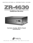
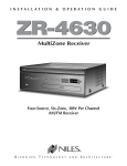
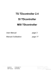
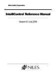
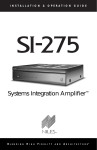
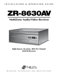
INSTALLATION
&
OPERATION
GUIDE
Systems Integration Amplifier
®
®
B
L E N D I N G
H
I G H
F
I D E L I T Y
A N D
A
R C H I T E C T U R E®
CONGRATULATIONS!
Thank you for purchasing the Niles SI-1260 Systems Integration Amplifier, one of the
most versatile and powerful multi-channel amplifiers ever offered. Like all Niles
products, the SI-1260 is built to the highest standards of quality and reliability. With
proper installation and operation, you'll enjoy years of trouble-free use.
Niles manufactures the industry's most complete line of custom installation components and accessories for audio/video systems. For a free full-line catalog write:
Niles, Catalog Request, P.O. Box 160818, Miami, Florida 33116-0818 or visit
www.nilesaudio.com.
TABLE OF CONTENTS
1
INTRODUCTION
2
FEATURES AND BENEFITS
3
SYSTEM DESIGN BASICS
5
SYSTEM DESIGN CONSIDERATIONS
6
APPLICATIONS
8
CONFIGURING YOUR SYSTEM
13
INSTALLATION CONSIDERATIONS
14
INSTALLATION
16
FRONT & REAR PANEL DETAILS
17
OPERATION
23
TROUBLESHOOTING GUIDE
27
CONFIGURATION WORKSHEET
29
SPECIFICATIONS
30
Designed for use in high-end/high-powered distributed audio systems, the SI-1260
Systems Integration Amplifier provides a level of performance, flexibility, and ease of
installation previously unavailable to custom installers. The SI-1260's unique design
enables each of its channels to be independently configured to reproduce stereo or
mono in any combination, as well as to compensate for differing volume levels in
rooms of different sizes. Additionally, the amplifier's Dual Bus Matrix™ feature and
multiple inputs enable it to be used in several different applications simultaneously
if desired (i.e. mono background music in some rooms and stereo in others).
INTRODUCTION
INTRODUCTION
As you read this manual and become more familiar with the SI-1260's capabilities,
you will understand why our multi-channel amplifier design has won many prestigious industry awards. The first multi-channel amplifier introduced by Niles, the SI1200, was selected Best New Product in 1994 by both Sound & Video Contractor
Magazine and the Custom Electronic Design and Installation Association (CEDIA). In
addition, the SI-1200 also won the Consumer Electronics Show's Innovations '95
Design and Engineering Award.
SI-1260
Systems Integration Amplifier
Figure 1
2
FEATURES AND BENEFITS
FEATURES AND BENEFITS
Microcontroller Based Real World Power
The SI-1260 12 channel amplifier incorporates microcontroller technology which
maximizes the amplifier's operational efficiency and enables it to deliver a solid 60
watts per channel into 8 ohms, 20Hz to 20kHz, 0.04% THD. Its power increases to
80 watts per channel into 4 ohms, 20Hz to 20kHz, at 0.06% THD. The massive
Multi-Tap Toroid power transformer features 6 independent secondary windings, one
for each of the six amplifier modules. This extraordinary power supply design provides the power necessary to deliver solid, deep, controlled bass response to a house
full of speakers.
Transparent Sound
The audio circuitry of the SI-1260 is constructed with the finest parts available
including the latest in discrete output transistor design, featuring 1% metal film
resistors, high quality capacitors and oversized heat sinks. All this attention to
technical detail results in a sound that is clear and uncolored.
Microcontroller Based Operation and Protection Modes
The SI-1260 utilizes advanced microcontroller based operation circuitry that monitors all facets of the amplifier's operation and protection modes: over/under line
voltage, main power fuse status, channel pair on/off status, thermal protection, short
circuit/low impedance protection and DC output protection. Additionally, easy to
see front panel LED indicators display the operation or protection mode for each
channel pair (CH1/2, CH3/4, CH5/6, CH7/8, CH9/10 and CH11/12) as well as for
the amplifier's main power supply, providing fast and easy troubleshooting. In the
unlikely event that a problem occurs on one channel pair, the other channels will
continue to play. When conditions return to normal, regular operation will resume.
Dual Input BusMatrix™ Selector
Nile’s unique Dual Input BusMatrix™ selector gives you the flexibility to individually
assign each amplifier channel to a BusMatrix™ input signal, either Left1, Right1,
Left1+Right1, Left2, Right2, Left2+Right2, or to a dedicated signal input. With the
BusMatrix™, routing surround sound to the master bedroom, stereo to the den, and
mono to a bathroom is as simple as flicking a switch. The Dual Input BusMatrix™
makes the SI-1260 an ideal multi-room or multi-zone amplifier, offering the professional installer exciting new features and sound system design possibilities.
3
Each of the SI-1260's six adjacent output pairs are bridgeable. You can create up to
six 120-watt channels by setting the bridging switch to the "BRIDGED" position.
These switches are located at the top of the rear panel (see Page 21 Figure 16).
Bridging enables you to double the power to specific speaker locations, including
large rooms and outdoor applications.
Freedom From Noise and Cross-Talk
The unique design of the SI-1260's Dual Input BusMatrix™ PC board ensures
extremely high channel-to-channel isolation. Signal-to-noise ratio and cross-talk
specifications are comparable to those of mixing consoles used in professional
recording studios. With the SI-1260, the music playing in the living room will not
interfere with the music playing in the den.
FEATURES AND BENEFITS
Twelve to Six Channel Configurable Power
Independent Level Controls
Each channel has its own independent volume level control, enabling you to
individually adjust the setting for up to twelve different speaker locations for optimum audio performance, providing uniform sound in every room.
Turn-On Modes
The SI-1260 features three selectable turn-on modes: (1) manual turn-on via the front
panel switch, (2) microcontroller enhanced audio sensing which activates only the
appropriate amplifier channels while leaving unused channel pairs off to eliminate
cross talk and (3) a 3-30 volt AC/DC voltage trigger input which enables voltage activation. Audio Sense and External Voltage trigger modes enable you to configure the
SI-1260 to turn on automatically in any kind of system configuration.
DB25 Audio & Voltage Trigger inputs
The SI-1260 incorporates a DB25 input connector to reduce wiring and installation time when using Niles Systems Integration Electronics. Niles multi-zone preamplifiers are equipped with a mating DB25 output connector. This output connector provides 6 zones of line-level audio signal output and a 12V Trigger
Voltage for reliable amplifier activation.
Designed in the USA
The Niles SI-1260 was designed in the USA by Niles engineers and includes a
two year parts and labor warranty.
4
SYSTEM DESIGN BASICS
SYSTEM DESIGN BASICS
As shown in Figure 2, a distributed audio/video system is
defined by the number of listening zones it has. Within a listening zone you can listen to
only one (1) source (e.g. CD,
Radio, Tape, etc.) at any one
time. A listening zone can consist of a single room or a group
of rooms. To achieve different
volumes and greater convenience in different rooms within a zone, individual volume
controls can be used. Niles
makes volume controls in various styles and colors. When
designing your system, take
into account who will use the
system and when they will use
it. Consult your local Niles
dealer for more information.
A multi-zone system as shown
in Figure 3, offers the household more flexibility. For
instance, a family might have
their family room wired for surround sound and their living
room wired for background
music. In a two zone system,
the children can watch TV in
surround sound while Mom
and Dad are reading the paper
and enjoying background
music in the living room.
TAPE PLAYER
CD PLAYER
VCR
TV
A Single-Zone System allows
only one source to be heard
throughout the house at a
given time.
RECEIVER
FAMILY ROOM
LIVING ROOM
LISTENING ZONE 1
Figure 2 - Single Zone System
TAPE PLAYER
CD PLAYER
VCR
TV
RECEIVER
RECEIVER
LIVING ROOM
FAMILY ROOM
LISTENING ZONE 1
LISTENING ZONE 2
Figure 3 - Multi-Zone System
5
Speaker Compatibility
A single channel (not bridged) of the SI-1260 is capable of driving a low impedance speaker load. As many as three eight ohm speakers can be safely connected to a single channel, presenting the amplifier a 2.66 ohm load. Proper ventilation of the SI-1260 is critical when driving low impedance loads. If the SI-1260
is not properly ventilated, the protection circuits may activate and shut off the
channel at higher volume levels (for more information on proper amplifier placement, see Installation Considerations on page 14).
A channel pair that has been BRIDGED is capable of driving an impedance load
of 4 ohms. Proper ventilation of the SI-1260 is critical when driving a 4 ohm load
with bridged channels. If the SI-1260 is not properly ventilated, the protection circuits may activate and shut off the channel at higher volume levels (for more
information on proper amplifier placement, see Installation Considerations on
page 14).
SYSTEM DESIGN CONSIDERATIONS
SYSTEM DESIGN CONSIDERATIONS
When designing your system, try to specify 6-8 ohm speakers (Niles offers a complete line of in-wall, in-ceiling, outdoor and home theater loudspeakers with all
models rated from 6-8 ohms).
Cable and Wire
Because the SI-1260 has many connections on the rear panel (see Figure 13), it is
important that you correctly label all of the input cables and speaker wires. Label the
cables and wires with their destination or source, rather than the SI-1260 terminal to
which they are connected. This will make it easier to reconfigure your system in the
future.
The SI-1260 connects to your sources via shielded line level audio cables with RCA connectors. Use high quality cables with your Niles amplifier for the lowest possible noise
and best overall performance. Your Niles dealer can recommend the proper cable.
A DB25 Multi-Zone Input Connector is provided for use with Niles Multi-Zone
Products which include a mating DB25 output connector. All 12 dedicated inputs
are included within the single connector, along with the SI-1260's Voltage Trigger
Input.
The SI-1260 connects to your speakers using two conductor speaker wire. For most
applications, we recommend you use 16 or 18 gauge wire. For wiring runs longer
than 80 feet, we recommend 14 gauge wire. The SI-1260's high-quality, gold-plated
5-way binding posts will accommodate up to 12-gauge wire. Attaching banana
plugs to the wire will enable the connection of larger wire sizes.
6
SYSTEM DESIGN CONSIDERATIONS
Using Mono For Smoother Coverage
In large or irregularly shaped rooms, you may find that the main listening area may be
closer to one of the speakers. If the speakers in the room are connected to a stereo
amplifier you will only hear half the music. The SI-1260's BusMatrix™ enables you to
create mono sound from one speaker without impacting the stereo quality in the rest
of the system. You can configure each room to either stereo or mono as needed with
no ill effects. Some of the most popular areas where mono will greatly enhance the
sound quality would be:
• Large rooms with many seating areas and/or many pairs of speakers.
• Irregularly shaped rooms.
• Bathrooms with one speaker over the tub and one speaker over the sink(s).
• Hallways or passageways (including those with multiple speakers).
• Small rooms, such as walk-in closets where more than a single speaker is not
required.
Bridging Channels for Areas that Require More
Volume and Power
There are several situations where bridging is an excellent way to improve the
sound. There are also applications where bridging would seem to be appropriate but
is not recommended. Bridging channels increases the power to 120 watts per channel with an 8 ohm impedance.
These are some of the most common Do's and Don'ts:
1. Outdoors (DO) - Sound dissipates faster outside than it does in a room where the
walls enclose the sound and reflect it back to the listener. A pair of speakers playing into a large patio or yard will greatly benefit from bridging four channels into
two 120 watt channels.
2. Surround Sound Systems (DO) - The dynamic demands for the center channel
are much greater than the left, right or surround channels. This is an excellent
application for two channels to be bridged into one 120 watt channel.
3. More than one pair of 8-ohm speakers (DON'T) - In a large room or a long hallway, often the best way to get good background music is to install multiple pairs of
speakers. You will actually deliver more power to two pairs of 8 ohm speakers by
using two unbridged amplifier channels than you would if you bridged four amplifier channels into two and connected the two pairs of speakers in parallel.
7
Advantages of Using The SI-1260 in a Single Zone System
By connecting a Niles SI-1260 to a stereo receiver's preamplifier outputs, you dedicate
a robust 60 watts to each speaker in your multi-room system. Each channel has its own
level control, enabling you to compensate for architectural differences which may
cause one speaker to seem louder than another. In addition, you can fine tune the system so that when all of the room volume controls are set to the loudest level, the large
rooms and the small rooms play at the same volume.
DSS
VCR
APPLICATIONS
APPLICATIONS
CD
Preamplifier or
AM/FM receiver
SI-1260
Niles VCS-2D
Volume Control
Room 1
Room 2
Room 3
Room 4
Room 5
Room 6
Single Zone
Figure 4 - Single Zone
8
APPLICATIONS & SYSTEM DESIGN CONSIDERATIONS
Creating a Low-Cost Second Zone
Using A Dedicated Source
The main problem in a single zone system is that when a source is being listened to
in one room, you cannot listen to another source in another room simultaneously.
However, for a listener who only listens to CDs, a low-cost second zone may be created to allow simultaneous CD listening while the main system is playing another
source. This is possible only if the CD player you are using has dual audio outputs,
one with remote controllable volume and the other a fixed volume. As shown in
Figure 5, you connect the CD player's variable output to the SI-1260's dedicated
channel inputs for the particular room where you will listen only to CDs. The fixed
output is connected to the main preamp or receiver so you can also listen to CDs in
the rest of the house. The finishing touch is to install a Niles infrared repeater system
(IRR-4D, IRP-2+ and IRC-2) so you may adjust the CD player's volume via remote
control from your CD listening room.
DSS
VCR
CD
(Fixed)
Preamplifier or
AM/FM receiver
IRC-2
(Variable)
BusMatrix™ Input 1
BusMatrix™ Input 2
I
SI-1260
FLASHERS
Niles VCS-2D
Volume Control
IRP-2+
Niles IRR-4D+
IR Sensor
ZONE 1
Figure 5 - Low Cost Second Zone for CDs
9
ZONE 2
Most of today's Dolby Digital surround sound receivers include a second zone preamplifier output used to create a second listening zone. Using this output with one
of the SI-1260's BusMatrix™ inputs provides amplification for multiple rooms within
a second listening zone as shown in Figure 6.
DVD/CD
CHANGER
VCR
DSS
APPLICATIONS
Using A Dual-Zone Receiver for Two Listening Zones
Second Zone Output
Dual Zone Surround
Sound Receiver
ZONE 1
(Home Theater)
Front Speakers
Center Speaker
Rear Speakers
BusMatrix Input 1
™
Niles VCS-2D
Volume Control
Living Room
Niles VCS-2D HP
Volume Control
(HP = High Power)
SI-1260
Kitchen
Exercise Room
(Unbridged Channels1-8)
Hallway
Patio
(Bridged Channels
9-10, 11-12)
Figure 6 - Using a Dual Zone Receiver
10
Adding Preamps To Create More Listening Zones
APPLICATIONS & SYSTEM DESIGN CONSIDERATIONS
In the ultimate multi-zone system, you would connect six stereo preamplifiers (or a
single component multi-zone/multi-source preamplifier) to one SI-1260, creating six
completely independent listening zones. Multi-zone systems enable listeners located in six separate zones to simultaneously listen to different source components as
shown in Figure 7.
AM/FM
TUNER
DSS
DVD/CD
CHANGER
Niles A4.6Ci
Zone Outputs
Dedicated Inputs
SI-1260
ZONE 1
ZONE 2
ZONE 3
ZONE 4
ZONE 5
Figure 7 - Creating More Listening Zones
11
ZONE 6
Utilizing the Dual BusMatrix™ Input
DVD/CD
CHANGER
AM/FM
TUNER
DSS
Zones 3-6
ZONE 3
SI-1260
Niles A4.6Ci
Zones 1-2
BusMatrix™ Input 1
BusMatrix™ Input 2
ZONE 4
SI-1260
Niles VCS-2D
Volume Control
ZONE 5
ROOM 1
ROOM 2
ZONE 1
ROOM 3
ROOM 4
ROOM 5
ZONE 2
APPLICATIONS & SYSTEM DESIGN CONSIDERATIONS
Many multi-zone systems incorporate multiple rooms within a single zone. The
SI-1260’s Dual BusMatrix™ Input simplifies the connections required for this system
design. As shown in Figure 8, a Niles A4.6Ci Multi-zone Controller has its first and
second zone outputs connected to the SI-1260’s Dual BusMatrix™ #1 and #2 inputs
respectively. Bus Input #1 is then routed to amplifier channels one through six via
dip switch settings. Bus Input #2 is routed to amplifier channels seven through twelve
in the same manner. Six rooms can now be connected to the
SI-1260 placing three rooms in Zone #1 and three rooms in Zone #2. The remaining zone outputs on the A4.6Ci can be connected to another SI-1260 for more zones.
ROOM 6
ZONE 6
Figure 8 - Dual BusMatrix™ Input
12
CONFIGURING YOUR SYSTEM
CONFIGURING YOUR SYSTEM
The SI-1260 offers many configuration possibilities. Therefore, carefully plan the
installation before starting. Start by drawing a block diagram of your system and use
the Configuration Worksheet on page 29 to document how you plan to connect
your SI-1260. Figure 9, shown below, is an example of a Configuration Worksheet
filled out according to the block diagram (figure 6) on page 10.
Figure 9
Sample Configuration Worksheet
BUS INPUTS & OUTPUTS
Second Zone Left Output
Right Bus Input # 1
Second Zone Right Output
Left Bus Input # 2
N/S
Right Bus Input # 2
N/S
Cascade Output Bus # 1 Right
N/S
Cascade Output Bus # 1 Left
N/S
Cascade Output Bus # 2 Right
N/S
Cascade Output Bus # 2 Left
N/S
CH #
BRIDGED
1
2
3
4
5
6
7
8
9
10
11
✓
✓
12
MODE SETTINGS
Constant
Audio Sense
Voltage Trigger
Control Output
13
CONNECTED TO. . .
Left Bus Input # 1
DIP
L1
R1
L1
R1
L1
R1
L1+R1
L1+R1
Off
L1
Off
R1
IN USE
✓
INPUT SOURCE
SPEAKER
Bus #1
Bus #1
Bus #1
Bus #1
Bus #1
Bus #1
Bus #1
Bus #1
N/S
Bus #1
N/S
Bus #1
Left Living Room
Right Living Room
Left Kitchen
Right Kitchen
Left Exercise Room
Right Exercise Room
Hallway #1
Hallway #2
N/S
Left Patio
N/S
Right Patio
SPECIAL CONNECTIONS OR NOTES
Automating the turn-on of your SI-1260 is one of the easiest steps when installing it
in a distributed system. However, do not plug the main power cord into the switched
AC outlet of your preamplifier or receiver. The high power design of the SI-1260
requires large amounts of current from its AC power source. Additionally, it is always
recommended to activate the system preamplifier/receiver before turning on your
SI-1260 in order to prevent system “turn-on thumps”. In order to address these
important needs, the SI-1260 has three special turn-on modes that let you turn the
amplifier on only when it is needed. These three options are accessed by the TurnOn Mode selector switch (see Figure 10).
Important! The Front Panel Power Switch must be in the ON (switch in) position for
any of the three turn-on options to function (refer to page 23 for more information
concerning the Front Panel Power Switch).
Turn-On Modes
INSTALLATION CONSIDERATIONS
INSTALLATION CONSIDERATIONS
Constant: The auto turn-on circuitry is "OFF".
The front panel master power switch operates
the amplifier. When the switch is in, the amp
is "ON", when it is out, the amp is "OFF".
Audio Sense: The amplifier is "OFF" when
there is no audio signal present at any of the
16 inputs, but the sensing circuitry is active.
The turn-on sensing circuitry looks for a tiny
amount of audio signal present at any of the
audio inputs. If it detects a signal, the adjacent
Figure 10 - Turn-On Mode.
pair of amplifier channels (i.e. channel 1/2,
3/4, 5/6, etc.) assigned to receive the input signals will switch "ON". Once the audio
signal stops, the sensing circuit waits approximately 2-minutes, then switches all
amplifier channels "OFF".
3-30V AC/DC Trigger Input: The amplifier is "OFF" when a 3 to 30-Volt AC or DC
signal is not applied to the voltage trigger input. Once the sensing circuitry detects
such a voltage, all adjacent pairs of amplifier channels that are receiving an audio
signal switch "ON". Once the voltage is removed, the Voltage Trigger circuit instantly switches the amplifier "OFF". Voltage triggers may be supplied by Niles automated switchers, some video projectors, some surround sound processors, or a 12 Volt
DC wall adapter (Niles FG00665) plugged into the switched outlet of your stereo
receiver.
If you are using a wall adapter or external power supply to provide the trigger, it
doesn't have to be very large (a minimum current capability of 2.5-milliamps for a 3
Volt trigger increasing up to a minimum of 38 milliamps for a 30-Volt trigger).
14
INSTALLATION CONSIDERATIONS
Placement
CAUTION! Placing the SI-1260’s weight on the rear or front panels will cause damage to the amplifier’s connectors or controls.
Place the SI-1260 on a flat, level surface like a table or shelf. The SI-1260 must be
placed with its weight equally distributed on the unit's four feet. This amplifier, like
any high-fidelity component, will last much longer if it is given adequate ventilation
for proper cooling. When installing the SI-1260 in a cabinet, be sure that the cabinet's rear is open to fresh air (see Figure 11). Additionally, place the SI-1260 so that
there are at least 6 inches of free air space above the amplifier and 1 inch on each
side. If the amplifier is located on a carpeted surface, place a board under the amplifier's feet. If the cabinet's design will not accommodate an open rear, install two small
"boxer fans" to provide continuous air flow into and out of the cabinet (see Figure 12).
CAUTION! When using low impedance speaker loads (less than 4 ohms Normal
Mode, less than 8 ohms Bridged Mode), refer to figure 12 for proper placement.
CAUTION! DO NOT block the ventilation holes on the top and bottom of the SI1260.
The SI-1260 is equipped with a massive toroidal power transformer. This transformer
generates a powerful magnetic field that could induce a hum in a turntable (particularly a turntable equipped with a moving coil cartridge). DO NOT place a turntable
directly above or directly adjacent to the SI-1260.
CAUTION! Before placing the SI-1260 on a shelf, verify that the weight bearing
capacity of the shelf is 70 lbs or greater.
Figure 11
Figure 12
Boxer Fan (105 CFM)
directly centered 6”
on top of the SI-1260.
Boxer Fan (105 CFM)
directly centered 2”
behind the SI-1260.
Make sure that there is a minimum
of 6” of free air space above the
amplifier and 1” on each side for
proper ventilation.
Allow a minimum of 2” of depth
behind the unit to accommodate
cables and connectors .
15
If the cabinet rear is not open to fresh
air or if your using low impedance
loads, install two “boxer fans” to provide continuous air flow into and out
of the cabinet.
Line Level Audio Inputs
Caution! The amplifier must be off whenever you make changes to the input connections.
STEP
DESCRIPTION
1. Correctly label the interconnecting
cables coming from each source.
Use audio patch cables terminated with
RCA connectors.
2. Connect the sources by inserting the
RCA connectors into a BusMatrix™
input or dedicated input jack on the
SI-1260's rear panel.
Connect outputs from your source components to the input jacks on the amplifier.
NEVER connect a preamplifier or source
input (e.g., record inputs) to the SI-1260
inputs.
INSTALLATION
INSTALLATION
NOTE: When you are using two amplifier channels in the "bridged" mode,
assign the audio signal to be amplified to the EVEN numbered amplifier
channel using the BusMatrix™ Dip
Switches.
Cascade Audio Outputs
The "Cascade Audio Outputs" enable you to connect additional amplifiers to your
preamplifier's output. Connection is accomplished with standard RCA interconnect
cables. The outputs are not buffered; to daisy chain more than five Niles amplifiers
you will need a Niles AVDA-3 buffered distribution amplifier. A single AVDA-3
enables you to daisy chain five amplifiers from each of three outputs. This allows 15
SI-1260 power amplifiers to be fed from the same master preamplifier. If your preamplifier has a vacuum tube output stage, you must use a Niles AVDA-3 to drive
more than one SI-1260.
AC Power Plug
STEP
DESCRIPTION
1. Plug the SI-1260’s attached 2 prong
power cord into a correctly grounded
120 Volt, 60-Hz wall outlet.
If you use a grounded power strip, surge
protector, or extension cord, verify that the
proper ground is maintained
CAUTION! DO NOT PLUG THE SI-1260'S
POWER CORD INTO A PREAMPLIFIER'S CONVENIENCE OUTLET.
1. The SI-1260 draws a maximum of about
890 watts from an AC wall outlet. This is
much more than the typical accessory
outlet on a component's rear panel can
provide.
2. Use the SI-1260's auto turn-on circuitry
to switch "ON" the SI-1260 when the
preamplifier is "ON".
16
Figure 13
FRONT AND REAR PANEL DETAILS
Red “Power” LED confirms the amplifier is connected to a live AC
outlet and that the front panel switch is on. Additionally, it indicates
any AC line voltage problems and main power fuse status.
Front panel “Master Power”
switch turns off the entire
amplifier, including the auto
turn on circuitry.
Cascade outputs of the
bus input enable you to daisy
chain multiple amplifiers.
BusMatrix™ controls for each
channel.
Gold Plated Dual Bus
Inputs, selectable by the
BusMatrix™, provide
enhanced input flexibility.
“Turn-On” Mode Switch.
3.5 mm Jack for
3-30V AC/DC trigger input.
3.5 mm Jack for
12v DC Control Output.
(150 mA max)
17
Level controls for each
channel.
Bridging switch for each channel pair.
Attractive extruded
aluminum front panel.
FRONT AND REAR PANEL DETAILS
Multi-color “Channel Pair” LED indicators
display channel pair on/off status,
and protection modes.
DB-25 input connector for simplified dedicated
audio and voltage trigger connection using
Niles Multi-Zone Products.
Gold-plated RCA jacks for the
dedicated inputs.
Serial Number.
Removable Two-prong
IEC compatible
AC power cord.
Gold plated, dual banana plug
spaced, five-way speaker
binding posts.
18
Speaker Wire Connections
INSTALLATION
CAUTION! All speaker wire connections must be made with the amplifier OFF.
Figure 14 - Binding Posts
STEP
DESCRIPTION
1. Label all wires.
If all wires connecting to the SI-1260 are
labeled with their destination rather than
their specific connection to the SI-1260, it
will be easier to reconfigure the system in
the future.
2. Connect one stripped wire end or
banana plug to the black terminal
and one to the red terminal.
A. Split the speaker wire insulation at least
2 inches.
CAUTION! NOT EVEN A SINGLE
STRAND OF WIRE CAN BE ALLOWED
TO TOUCH THE AMPLIFIER CHASSIS
OR ANOTHER CONNECTOR.
19
Banana Plugs
There are many types of
banana plugs available.
Some are crimped onto
the speaker wire and
some are soldered. Niles
offers banana plugs that
have a quick-connect
binding system for the
speaker wire included
within the banana plug
itself. After the wire is
attached, the banana
plug is simply inserted
into the hole at the end
of the amplifier's speaker binding post. Dual
spaced banana plugs
will fit the SI-1260 binding posts.
Bare Wire
Unscrew the red or
black plastic knobs and
insert the bare wire
through the hole in the
post. Tighten the knob
until the wire is securely clamped.
B. Strip 1/2 inch of insulation from each
speaker wire conductor.
C. Attach banana plugs or twist the wire
strands of each conductor and insert them
into the appropriate SI-1260 binding post.
BusMatrix™ Input DIP Switch Settings
DIP Switch Settings
1L is for the assignment of the Left Bus Input #1
1R is for the assignment of Right Bus Input #1
1L+1R is for the assignment of a summed mono signal of the Left and Right Bus Input#1
2L is for the Left Bus Input #2
2R is for the Right Bus Input #2
2L+2R is for a summed mono signal of the Left and Right Bus Input #2
The seventh switch assigns the dedicated input to its respective channel
Again, only one of the seven DIP switches
should be configured to the "ON" position
(switched to the right).
INSTALLATION
Each channel has a dedicated BusMatrix™ DIP switch bank that assigns that channel's source input signal (see Figure 15). To assign the BusMatrix™ source input signal for a particular channel, set only one of the seven switches to the right.
“OFF” Position “ON” Position
Figure 15 - BusMatrix™ DIP Switches
STEP
DESCRIPTION
1. Move only one (1) DIP switch to the
"ON" position for each channel.
CAUTION! EACH DIP SWITCH ALLOWS
YOU TO MOVE ALL SEVEN SLIDE
SWITCHES TO THE "ON" POSITION. IF
YOU SET MORE THAN ONE SLIDE
SWITCH TO "ON" YOU MAY CREATE
AN UNDESIRABLE MIX OF INPUTS ON
THE ENTIRE BUS.
20
Bridging Two Channels into One
INSTALLATION
The SI-1260's bridging switches allow you to create a more powerful amplifier channel by combining or "bridging" two adjacent amplifier channels together into one.
Figure 16
Channel Bridging Switch and DIP Switches
Slide the bridgWhen two channels are bridged
ing switch in the together, connect speakers to the
direction of the
two terminals labeled “Bridged”.
arrow to bridge
two adjacent
amplifier channels. Set the
controls of the
newly bridged
pair by using the
EVEN numbered
channel.
STEP
DESCRIPTION
1. Choose which of the six pairs you
wish to bridge and move the bridging
switch for that pair to the "Bridged"
position (toward arrow).
The 12 channels are grouped into 6 pairs
(e.g. 1 & 2). Only the two channels within a
pair can be bridged. Thus, only channels 1
and 2, or channels 3 and 4 could be
bridged. Channel 2 and 3 are not a pair and
cannot be bridged.
CAUTION! DO NOT CONNECT A
SPEAKER LOAD OF LESS THAN 4
OHMS TO A BRIDGED CHANNEL.
Each bridged channel is designed for a 4
ohm minimum load. Connecting multiple
speakers to a single channel, creating a
nominal impedance of less than 4 ohms
may cause the SI-1260 to go into protection
mode or be damaged.
2. Connect the speaker wires to the
two bridged speaker terminals
(BRIDGED+, BRIDGED-). Carefully
observe the polarity markings.
Connect the speaker wires to the two adjacent amplifier channel's RED terminals only.
NOTE: If one of the speaker wires touches a
BLACK terminal, you will short-circuit the
amplifier.
CAUTION! DO NOT CONNECT A
HEADPHONE JUNCTION BOX TO THE
OUTPUT OF A BRIDGED CHANNEL
PAIR.
3. Use the EVEN NUMBERED BusMatrix™
switch bank and level control for the
adjustments and configuration of a
bridged channel.
21
Figure 17
Bridged Channel Connections
These connections to a bridged channel
pair will cause either thermal shutdown
or poor quality sound.
When two channels are bridged into one,
ensure that the odd numbered DIP
switches are all in the "OFF" position.
Setting the Turn-On Mode Switch
Figure 18
Slide the switch with either your fingernail
or a 1/8” slotted screwdriver blade.
The Control Output
INSTALLATION
The SI-1260 has three (3) turn-on modes. Select the desired mode by sliding the
mode switch to the proper position. See Installation Considerations on page 14 and
Figure 10 for more information about each of the turn-on modes.
Figure 19
As shown in Figure 19, a 3.5 mm female miniplug output jack on the rear panel of the SI-1260
provides a 12V DC trigger signal. It is suitable for
triggering Niles automated switchers, some
motorized screens and electric curtain controls
and other devices that require a constant 12V
DC control voltage for activation.
Using the
3.5 mm jack.
This voltage is provided only when any of the
amplifier channels are active or "ON". When all
amplifier channels are "OFF", the 12V signal is
"OFF".
STEP
DESCRIPTION
1. Check the requirements of the
device you want to control.
The control output provides 150 mA of
current maximum.
2. Connect the 3.5mm jack to the
control output maintaining proper
polarity (tip = +)
Niles makes an accessory cable
plug FG00724.
22
OPERATION
OPERATION
Front Panel Power Switch
The SI-1260's master power switch is located on the front panel. Pressing the switch
toggles between the ON (switch in) and the OFF (switch out) position. It must be in the
ON position to enable the amplifier to activate regardless of the turn-on mode selected
(see page 14). If you are going on vacation and/or would like to reduce power consumption while you are away, set the master power switch to the OFF position. When
you would like to return to normal operation, set the switch back to the ON position.
Power LED Indicator
The SI-1260 features a bi-colored POWER LED indicating the power status of the
amplifier:
POWER LED
STATUS
OFF
Amplifier is not plugged in to a live AC outlet.
Solid Yellow
The amplifier is plugged into a live AC outlet and the main
power switch is OFF (out position).
Solid Red
The amplifier is plugged into a live AC outlet and the main power
switch is ON (in position).
Fast Red Blinking
The AC line voltage is above or below the normal 120VAC.
This will cause the amplifier to turn off.
(Three Times Per Second)
Normal operation resumes once the AC line voltage returns
to 120VAC.
Slow Red Blinking
(Once Every Three Seconds)
23
Internal defect. The amplifier should be returned to Niles
for service.
The SI-1260 incorporates individual multi-colored LEDs for each channel-pair
that indicate the following:
CHANNEL PAIR LED
STATUS
OFF
The channel pair is OFF.
Solid Green
The channel pair is active and operating normally.
Fast Red Blinking
Indicates a possible short circuit or low impedance condition.
Speaker wire strands that are touching at the speaker or the amplifier's speaker terminals and/or a damaged speaker wire can cause
a short circuit. More than three pairs of 8 ohm speakers attached
to the same amplifier channel present the amplifier channel with a
low impedance. Both of these conditions will cause the LED indicator to blink red very quickly. Eliminating the short circuit or connecting a proper speaker impedance load will enable the channel
pair to resume normal operation.
(Three Times Per Second)
Slow Red Blinking
(Once Every Three Seconds)
Solid Red
OPERATION
Channel Pair LED Indicators
Indicates the channel pair is overheating due to inadequate
ventilation. Providing proper airflow to the amplifier will
eliminate this problem (refer to page 15, figures 11 and 12 for
amplifier placement details).
There is a damaged internal component in this channel pair
module. The amplifier should be returned to Niles for service.
24
OPERATION
Using Level Controls as Limiters
Using the individual level controls, the SI-1260 enables you to set a specific volume
level for each of the different rooms connected. Individual room volume levels can
be calibrated so that all rooms have similar volume control characteristics regardless of size and acoustics and to establish a maximum volume level. This is especially useful if your system is remote controlled, or if some of the users like to play
the stereo too loudly.
Calibrate your system's volume levels using the steps outlined below:
1. Adjust all of the SI-1260's level controls to the minimum volume position. If there
are any other amplifiers in the system, adjust their level controls to the minimum.
(All of the amplifiers in your system must have level controls).
2. Adjust all individual in-wall volume controls to the loudest setting (fully clockwise).
3. Play a loud radio station.
4. Increase the preamplifier or receiver's volume up slowly. If you hear any sound,
lower the preamplifier's volume again and recheck all amplifier levels, they must
be at minimum. If no sound is heard when the preamplifier is turned all the way
up, proceed to step five.
5. Have someone step into each room and listen as you adjust each level control on
the SI-1260 to the desired maximum level for that room.
6. Adjust the volume for each channel to achieve a good balance from the most used listening position in each room.
25
An output of 60 watts is adequate power to completely drown out conversation in
a normal sized room. Even at those levels, the SI-1260 will sound clear and clean.
Obviously, it requires more power to achieve a reasonable volume of sound in a
large room than it does in a small room. Even if you are normally very careful, it is
possible to turn the volume so high that the amplifier runs out of power. This creates "clipping" distortion.
OPERATION
Listening at Higher Volumes
Clipping distortion makes treble sound very harsh and unmusical. If you hear harsh
sounding treble from any speakers, immediately turn down the level controls for
the channel pairs connected to those speakers. These harsh sounds include powerful high frequency sound spikes that will quickly damage the tweeter of any loudspeaker.
If you continue to operate the amplifier at "clipping" power levels the protection
circuits will operate. The protection circuits will reset when output signal conditions have returned to normal. Perpetually over-driving your speakers and amplifier
is abuse and will void the manufacturer's warranty on all affected products.
Cleaning and Maintenance
The internal parts of the SI-1260 are electronic and require no maintenance.
Once a year it is appropriate to twist each input RCA connector to remove any
oxidation and improve conductivity.
You can clean the amplifier with soft cloth or a paper towel dampened with water.
DO NOT use any spray-type or abrasive cleaners on the amplifier.
26
TROUBLESHOOTING GUIDE
TROUBLESHOOTING GUIDE
When a problem occurs, consult this guide first. If the problem persists, or you
have additional questions, call your local Niles dealer or call Niles Technical
Support at 1-800-289-4434. The most common problems are related to hook-up.
Have your configuration worksheet handy when you call.
SYMPTOM
POSSIBLE CAUSES AND TEST PROCEDURE
Very low or no sound on
one channel.
1. BusMatrix™ DIP switch is not in the correct position.
Check your configuration worksheet and verify all
settings.
2. Audio cable to the input is bad. Connect the nonworking channel to a cable known to be good.
3. Bridging Switch is in wrong position. Check your configuration worksheet for the correct setting and verify.
No sound on one channel
pair and channel pair LED is
quickly blinking red.
1. Check that connections are secure and that there are
no loose strands of wires crossing from the positive
to the negative terminal at the back of the amplifier
and/or the speaker.
2. Disconnect the speaker wire at both ends; separate
the 2 conductors at both ends and test with a meter
for a short circuit. If there is no short, connect the
two conductors at one end and test for continuity.
3. Verify that the impedance load of the connected
speakers is not less than 2.66 ohms with an unbridged
channel and 4 ohms with a bridged channel.
No sound on one channel
pair and channel pair LED is
slowly blinking red.
The amplifier module has overheated due to inadequate
ventilation or prolonged operation at clipping levels.
1. Turn the amplifier off and allow the internal circuits
to cool.
2. Check to ensure that there is sufficient ventilation for
the amplifier. After a reasonable time has passed,
turn the amplifier back on and check the LED again.
3. Lower the level controls for that channel pair.
No sound on one channel
pair and channel pair LED is
solid red.
27
The amplifier module requires service.
Contact your Niles dealer for service information.
POSSIBLE CAUSES AND TEST PROCEDURE
Very low or no sound on
some or all channels.
1. Bridging Switch is in wrong position. Check your configuration worksheet for the correct setting and verify.
2. Audio cable to the input is bad. Connect a cable
known to be good to the non-working channel.
Hum from all of the speakers.
Hum can be caused due to a ground potential difference between connected components (especially those
connected to antenna or cable TV feeds).
1. Check for faulty cables; faulty source signals; an
ungrounded phono system, cable feed, and/or a
defective component.
2. Reverse the AC plug of components with non-polarized plugs.
TROUBLESHOOTING GUIDE
SYMPTOM
3. Test the AC receptacle using a Ground Tester.
Sound is distorted on one or
more channels at normal
volume.
No sound on any channels
and power LED is slowly
blinking.
Bass is weak and stereo
sound is "phasey".
1. DIP switch(es) are not in the correct position(s).
Check the worksheet and verify all settings.
2. If the channel pair LED is Yellow, then the channel is
being overdriven (volume set too high on the preamplifier). The channel volume level should be re-calibrated to avoid this condition (refer to page 25 for information on Using Level Controls as Limiters).
Amplifier has an internal defect requiring service.
Contact your Niles dealer for service information.
1. Check that the Bridging Switch is "OFF". If two adjacent channels are connected normally but the bridging switch is set to the "BRIDGED" position, the two
speakers will be out of phase.
2. The speakers are wired out of phase. Recheck polarity and reverse the connections on the back of one
speaker if necessary.
A speaker connected to a
bridged pair of amplifier
channels sounds weak.
Check that the Bridging Switch is "ON".
28
CONFIGURATION WORKSHEET
CONFIGURATION WORKSHEET
BUS INPUTS & OUTPUTS
CONNECTED TO. . .
Left Bus Input # 1
Right Bus Input # 1
Left Bus Input # 2
Right Bus Input # 2
Cascade Output Bus # 1 Right
Cascade Output Bus # 1 Left
Cascade Output Bus # 2 Right
Cascade Output Bus # 2 Left
CH #
BRIDGED
DIP
INPUT SOURCE
SPEAKER
1
2
3
4
5
6
7
8
9
10
11
12
MODE SETTINGS
Constant
Audio Sense
Voltage Trigger
Control Output
29
IN USE
SPECIAL CONNECTIONS OR NOTES
Design Principle
Linear voltage/current amplification.
Continuous Power Output (FTC Rated)
(Unbridged, all channels driven) 60 watts per channel at 8 ohms, 80 watts per
channel at 4 ohms.
SPECIFICATIONS
SPECIFICATIONS
Bridged Power Output
(Adjacent channels bridged, all channels driven) 120 watts per channel at
8 ohms.
Input Impedance
47,000 ohms
Input Sensitivity
100mv for 1 watt out; 850mv for full output, (60 watts) level controls set at maximum.
Overall Voltage Gain
29 dB
Frequency Response
Bandwidth from 5 Hz to 50 kHz
Distortion
(Normal mode)
0.06% THD 20Hz to 20kHz all channels driven (8 ohms)
0.06% THD rated 20Hz to 20kHz all channels driven (4 ohms)
(Bridged mode)
0.06% THD 20Hz to 20kHz all channels driven (8 ohms)
Overall Dimensions
17 inches wide by 7.375 inches high (including feet) by 15 inches deep.
Weight
70 pounds
30
Niles Audio
Corporation
12331 S.W. 130 Street
Miami, Florida 33186
Tel: (305) 238-4373
Fax: (305) 238-0185
www.nilesaudio.com
© 2000 Niles Audio Corporation. All rights reserved. Niles, the Niles logo, Blending High Fidelity
and Architecture, and Systems Integration Amplifier are registered trademarks of Niles Audio
Corporation. BusMatrix is a trademark of Niles Audio Corporation. All other trademarks are the
property of their respective owners. Because we constantly strive to improve our products, Niles
reserves the right to change product specifications without notice. The technical and other information contained herein is not intended to set forth all technical and other specifications of Niles
products. Additional information can be obtained on-line at www.nilesaudio.com or by calling
Niles at 1-800-289-4434. Printed in Taiwan. 06/00 DS00257A