1
INSTALLATION
&
OPERATION
GUIDE
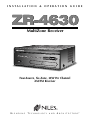
ZR-4630
MultiZone Receiver
Four-Source, Six-Zone, 30W Per Channel
AM/FM Receiver
B
L E N D I N G
T
E C H N O L O G Y
A N D
A
R C H I T E C T U R E™
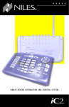
Congratulations!
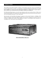
Thank you for purchasing the Niles ZR-4630 MultiZone Receiver, one of the most flexible and convenient audio
components ever offered. The ZR-4630, like all Niles products, is built to the highest standards of quality and
reliability. With proper installation and operation, you'll enjoy years of trouble-free use.
Niles manufactures the industry’s most complete line of custom installation components and accessories for
audio/video systems. To see the complete Niles product assortment, visit us on the Internet at:
www.nilesaudio.com
TABLE OF CONTENTS
INTRODUCTION . . . . . . . . . . . . . . . . . . . . . . . . . . . . . . . . . . . . . . . . . . . . . . . . . . . . . . . . . . . . . . . . . . . . . . . . . . . . . . .6
FEATURES AND BENEFITS . . . . . . . . . . . . . . . . . . . . . . . . . . . . . . . . . . . . . . . . . . . . . . . . . . . . . . . . . . . . . . . . . . . . . .7–8
PARTS GUIDE . . . . . . . . . . . . . . . . . . . . . . . . . . . . . . . . . . . . . . . . . . . . . . . . . . . . . . . . . . . . . . . . . . . . . . . . . . . . . . .9–10
R-4 REMOTE . . . . . . . . . . . . . . . . . . . . . . . . . . . . . . . . . . . . . . . . . . . . . . . . . . . . . . . . . . . . . . . . . . . . . . . . . . . . . . . . . .11
SOLO™ MASTER KEYPAD MODULE AND THE NUMERIC™ ACCESSORY KEYPAD MODULE . . . . . . . . . . . . . . . . . .12
SYSTEM CONFIGURATIONS . . . . . . . . . . . . . . . . . . . . . . . . . . . . . . . . . . . . . . . . . . . . . . . . . . . . . . . . . . . . . . . . . . . . .13
CONFIGURATION 1 - SIX ZONES . . . . . . . . . . . . . . . . . . . . . . . . . . . . . . . . . . . . . . . . . . . . . . . . . . . . . . . . . . . . . .13-14
CONFIGURATION 2 - ADDING ZONES USING MULTIPLE ZR-4630’S . . . . . . . . . . . . . . . . . . . . . . . . . . . . . . . . . . .15
CONFIGURATION 3 - DISTRIBUTING SOURCE-COMPONENT AUDIO SIGNALS . . . . . . . . . . . . . . . . . . . . . . . .16-17
CONFIGURATION 4 - INTEGRATING AN IR-CONTROLLED HOME THEATER . . . . . . . . . . . . . . . . . . . . . . . . . . . . .18
CONFIGURATION 5 - INTEGRATING A HOME THEATER USING AN INTELLICONTROL . . . . . . . . . . . . . . . . . . . .19
CONFIGURATION 6 - MULTIPLE SOLO™ MASTER KEYPAD MODULES IN A ZONE . . . . . . . . . . . . . . . . . . . . . . . . .20
CONFIGURATION 7 - MULTIPLE LISTENING AREAS IN A ZONE . . . . . . . . . . . . . . . . . . . . . . . . . . . . . . . . . . . . . . . .21
CONFIGURATION 8 - EXTERNAL AMPLIFIER IN A ZONE FOR MORE POWER . . . . . . . . . . . . . . . . . . . . . . . . . . . .22
CONFIGURATION 9 - EXTERNAL AMPLIFIER IN A ZONE FOR MULTIPLE LISTENING AREAS . . . . . . . . . . . . . . . . .23
CONFIGURATION 10 - EXTERNAL AMPLIFIER IN A ZONE FOR MULTIPLE ROOMS . . . . . . . . . . . . . . . . . . . . . . . .24
CONFIGURATION 11 - SYSTEM PAGING WITH AN EXTERNAL TELEPHONE SYSTEM . . . . . . . . . . . . . . . . . . . . . . .25
CONFIGURATION 12 - IR REPEATING FOR CONTROL OF LOCAL COMPONENTS . . . . . . . . . . . . . . . . . . . . . . . .26
COMPONENT COMPATIBILITY . . . . . . . . . . . . . . . . . . . . . . . . . . . . . . . . . . . . . . . . . . . . . . . . . . . . . . . . . . . . . . . . . .27
Infrared Command Compatibility . . . . . . . . . . . . . . . . . . . . . . . . . . . . . . . . . . . . . . . . . . . . . . . . . . . . . . . . . . . . . . .27
Testing for a Possible IR Command Conflict . . . . . . . . . . . . . . . . . . . . . . . . . . . . . . . . . . . . . . . . . . . . . . . . . . . . . . .27
Solving the IR Command Conflict if Present . . . . . . . . . . . . . . . . . . . . . . . . . . . . . . . . . . . . . . . . . . . . . . . . . . . . . . .27
2
TABLE OF CONTENTS
SOURCE POWER SYNCHRONIZATION . . . . . . . . . . . . . . . . . . . . . . . . . . . . . . . . . . . . . . . . . . . . . . . . . . . . . . . . . . . .28
CHOOSING A SYNCHRONIZATION METHOD . . . . . . . . . . . . . . . . . . . . . . . . . . . . . . . . . . . . . . . . . . . . . . . . . . .29
Video Sync . . . . . . . . . . . . . . . . . . . . . . . . . . . . . . . . . . . . . . . . . . . . . . . . . . . . . . . . . . . . . . . . . . . . . . . . . . . . . .29
Voltage Sync . . . . . . . . . . . . . . . . . . . . . . . . . . . . . . . . . . . . . . . . . . . . . . . . . . . . . . . . . . . . . . . . . . . . . . . . . . . . .30
Current Sensing . . . . . . . . . . . . . . . . . . . . . . . . . . . . . . . . . . . . . . . . . . . . . . . . . . . . . . . . . . . . . . . . . . . . . . . . . .30
Light Sensing . . . . . . . . . . . . . . . . . . . . . . . . . . . . . . . . . . . . . . . . . . . . . . . . . . . . . . . . . . . . . . . . . . . . . . . . . . . . .31
SOURCE AND HOME THEATER SYNC STATUS . . . . . . . . . . . . . . . . . . . . . . . . . . . . . . . . . . . . . . . . . . . . . . . . . . . .31
OPERATIONAL OVERVIEW . . . . . . . . . . . . . . . . . . . . . . . . . . . . . . . . . . . . . . . . . . . . . . . . . . . . . . . . . . . . . . . . . . . . . .32
MASTER KEYS/SOURCE BUTTONS . . . . . . . . . . . . . . . . . . . . . . . . . . . . . . . . . . . . . . . . . . . . . . . . . . . . . . . . . . . . .32
Master Key/Source Button Events . . . . . . . . . . . . . . . . . . . . . . . . . . . . . . . . . . . . . . . . . . . . . . . . . . . . . . . . . . . . . . . .33
Master Key/Source Button Operation . . . . . . . . . . . . . . . . . . . . . . . . . . . . . . . . . . . . . . . . . . . . . . . . . . . . . . . . . . . . .34
Single Zone Operation . . . . . . . . . . . . . . . . . . . . . . . . . . . . . . . . . . . . . . . . . . . . . . . . . . . . . . . . . . . . . . . . . . . . .34
System Wide Operation . . . . . . . . . . . . . . . . . . . . . . . . . . . . . . . . . . . . . . . . . . . . . . . . . . . . . . . . . . . . . . . . . . . .34
Zone Linked Operation . . . . . . . . . . . . . . . . . . . . . . . . . . . . . . . . . . . . . . . . . . . . . . . . . . . . . . . . . . . . . . . . . . . .34
OFF KEY/OFF BUTTON . . . . . . . . . . . . . . . . . . . . . . . . . . . . . . . . . . . . . . . . . . . . . . . . . . . . . . . . . . . . . . . . . . . . . .34
OFF Key Events . . . . . . . . . . . . . . . . . . . . . . . . . . . . . . . . . . . . . . . . . . . . . . . . . . . . . . . . . . . . . . . . . . . . . . . . . .35
OFF Key/Button Operation . . . . . . . . . . . . . . . . . . . . . . . . . . . . . . . . . . . . . . . . . . . . . . . . . . . . . . . . . . . . . . . . . .35
Single Zone OFF . . . . . . . . . . . . . . . . . . . . . . . . . . . . . . . . . . . . . . . . . . . . . . . . . . . . . . . . . . . . . . . . . . . . . . .35
System Wide OFF . . . . . . . . . . . . . . . . . . . . . . . . . . . . . . . . . . . . . . . . . . . . . . . . . . . . . . . . . . . . . . . . . . . . . .35
Zone Linked OFF . . . . . . . . . . . . . . . . . . . . . . . . . . . . . . . . . . . . . . . . . . . . . . . . . . . . . . . . . . . . . . . . . . . . . .35
VOLUME KEYS/VOLUME BUTTONS . . . . . . . . . . . . . . . . . . . . . . . . . . . . . . . . . . . . . . . . . . . . . . . . . . . . . . . . . . . .36
Volume Keys/Volume Buttons Operation . . . . . . . . . . . . . . . . . . . . . . . . . . . . . . . . . . . . . . . . . . . . . . . . . . . . . . .36
MUTE KEY/MUTE BUTTON . . . . . . . . . . . . . . . . . . . . . . . . . . . . . . . . . . . . . . . . . . . . . . . . . . . . . . . . . . . . . . . . . . .37
Mute Key/Mute Button Operation . . . . . . . . . . . . . . . . . . . . . . . . . . . . . . . . . . . . . . . . . . . . . . . . . . . . . . . . . . . .37
FUNCTION KEYS/BUTTONS . . . . . . . . . . . . . . . . . . . . . . . . . . . . . . . . . . . . . . . . . . . . . . . . . . . . . . . . . . . . . . . . . .38
Function Key/Button Operation for Connected Source Components . . . . . . . . . . . . . . . . . . . . . . . . . . . . . . . . . .38
Function Key/Button Operation for the Built-in Tuner . . . . . . . . . . . . . . . . . . . . . . . . . . . . . . . . . . . . . . . . . . . . .39
FRONT-PANEL TUNER OPERATION . . . . . . . . . . . . . . . . . . . . . . . . . . . . . . . . . . . . . . . . . . . . . . . . . . . . . . . . . . . .40
IDENTICAL SOURCE COMPONENTS . . . . . . . . . . . . . . . . . . . . . . . . . . . . . . . . . . . . . . . . . . . . . . . . . . . . . . . . . . .41
SHARED SOURCE COMPONENTS . . . . . . . . . . . . . . . . . . . . . . . . . . . . . . . . . . . . . . . . . . . . . . . . . . . . . . . . . . . . .41
3
TABLE OF CONTENTS
OPERATING A SYSTEM WITH MULTIPLE ZR-4630’s . . . . . . . . . . . . . . . . . . . . . . . . . . . . . . . . . . . . . . . . . . . . . . . .41
OPERATION A SYSTEM INTEGRATED WITH A HOME THEATER . . . . . . . . . . . . . . . . . . . . . . . . . . . . . . . . . . . . . .42
OPERATION FROM THE HOME THEATER ZONE . . . . . . . . . . . . . . . . . . . . . . . . . . . . . . . . . . . . . . . . . . . . . . . . . .42
1. Integrated Home Theater using 12V Home Theater Sync and IR Repeating . . . . . . . . . . . . . . . . . . . . . . . .42
2. Integrated Home Theater using 12V Home Theater Sync and Niles R-4 Commands . . . . . . . . . . . . . . . .42
3. Integrated Home Theater without Home Theater Sync and using Niles R-4 Commands . . . . . . . . . . . . . .43
SYSTEM-BUSY INDICATION . . . . . . . . . . . . . . . . . . . . . . . . . . . . . . . . . . . . . . . . . . . . . . . . . . . . . . . . . . . . . . . . . . .43
PAGING INDICATION . . . . . . . . . . . . . . . . . . . . . . . . . . . . . . . . . . . . . . . . . . . . . . . . . . . . . . . . . . . . . . . . . . . . . . .43
INSTALLATION . . . . . . . . . . . . . . . . . . . . . . . . . . . . . . . . . . . . . . . . . . . . . . . . . . . . . . . . . . . . . . . . . . . . . . . . . . . . . . . .44
PLACEMENT . . . . . . . . . . . . . . . . . . . . . . . . . . . . . . . . . . . . . . . . . . . . . . . . . . . . . . . . . . . . . . . . . . . . . . . . . . . . . . .44
CONNECTIONS . . . . . . . . . . . . . . . . . . . . . . . . . . . . . . . . . . . . . . . . . . . . . . . . . . . . . . . . . . . . . . . . . . . . . . . . . . . . . . .44
Connecting Speaker Wire . . . . . . . . . . . . . . . . . . . . . . . . . . . . . . . . . . . . . . . . . . . . . . . . . . . . . . . . . . . . . . . . . . . . .44
Terminating Four-Pair Twisted Cable . . . . . . . . . . . . . . . . . . . . . . . . . . . . . . . . . . . . . . . . . . . . . . . . . . . . . . . . . . . . . .45
Connecting the Solo™ Master Keypads to the Home Run of Four-pair Twisted Cable . . . . . . . . . . . . . . . . . . . . . . .45
Connecting Numeric™ Keypads . . . . . . . . . . . . . . . . . . . . . . . . . . . . . . . . . . . . . . . . . . . . . . . . . . . . . . . . . . . . . . . .45
Connecting IR Sensors . . . . . . . . . . . . . . . . . . . . . . . . . . . . . . . . . . . . . . . . . . . . . . . . . . . . . . . . . . . . . . . . . . . . . . . .46
Source-Component Power and Home Theater Synchronization Signals . . . . . . . . . . . . . . . . . . . . . . . . . . . . . . . . . .47
Keypad Modules . . . . . . . . . . . . . . . . . . . . . . . . . . . . . . . . . . . . . . . . . . . . . . . . . . . . . . . . . . . . . . . . . . . . . . . . . . . .47
System Expansion . . . . . . . . . . . . . . . . . . . . . . . . . . . . . . . . . . . . . . . . . . . . . . . . . . . . . . . . . . . . . . . . . . . . . . . . . . .48
IR Flashers . . . . . . . . . . . . . . . . . . . . . . . . . . . . . . . . . . . . . . . . . . . . . . . . . . . . . . . . . . . . . . . . . . . . . . . . . . . . . . . . .48
Home Theater Control System . . . . . . . . . . . . . . . . . . . . . . . . . . . . . . . . . . . . . . . . . . . . . . . . . . . . . . . . . . . . . . . . .48
12V Control Signals . . . . . . . . . . . . . . . . . . . . . . . . . . . . . . . . . . . . . . . . . . . . . . . . . . . . . . . . . . . . . . . . . . . . . . . . .48
AM/FM Antennas . . . . . . . . . . . . . . . . . . . . . . . . . . . . . . . . . . . . . . . . . . . . . . . . . . . . . . . . . . . . . . . . . . . . . . . . . . . .48
Source-Component Audio Signals . . . . . . . . . . . . . . . . . . . . . . . . . . . . . . . . . . . . . . . . . . . . . . . . . . . . . . . . . . . . . .48
Telephone Paging . . . . . . . . . . . . . . . . . . . . . . . . . . . . . . . . . . . . . . . . . . . . . . . . . . . . . . . . . . . . . . . . . . . . . . . . . . . .48
Preamplifier Zone Outputs . . . . . . . . . . . . . . . . . . . . . . . . . . . . . . . . . . . . . . . . . . . . . . . . . . . . . . . . . . . . . . . . . . . .48
Speakers . . . . . . . . . . . . . . . . . . . . . . . . . . . . . . . . . . . . . . . . . . . . . . . . . . . . . . . . . . . . . . . . . . . . . . . . . . . . . . . . . . .48
AC Power . . . . . . . . . . . . . . . . . . . . . . . . . . . . . . . . . . . . . . . . . . . . . . . . . . . . . . . . . . . . . . . . . . . . . . . . . . . . . . . . . .48
Connecting an IR Sensor for Local System Control . . . . . . . . . . . . . . . . . . . . . . . . . . . . . . . . . . . . . . . . . . . . . . . . . .49
Connecting an A/B Amplifier Switch for Local System Selection . . . . . . . . . . . . . . . . . . . . . . . . . . . . . . . . . . . . . . .50
4
TABLE OF CONTENTS
PROGRAMMING OVERVIEW . . . . . . . . . . . . . . . . . . . . . . . . . . . . . . . . . . . . . . . . . . . . . . . . . . . . . . . . . . . . . . . . . . . .51
Installer Programming Panel . . . . . . . . . . . . . . . . . . . . . . . . . . . . . . . . . . . . . . . . . . . . . . . . . . . . . . . . . . . . . . . . . . .51
Programming Documentation . . . . . . . . . . . . . . . . . . . . . . . . . . . . . . . . . . . . . . . . . . . . . . . . . . . . . . . . . . . . . . . . . .51
ZR-4630 Programming Worksheet
. . . . . . . . . . . . . . . . . . . . . . . . . . . . . . . . . . . . . . . . . . . . . . . . . . . . . . . . . . . . .52
ZR-4630 Source-Component Programming Worksheet . . . . . . . . . . . . . . . . . . . . . . . . . . . . . . . . . . . . . . . . . . . . . . .53
Function Keys/Buttons Programming . . . . . . . . . . . . . . . . . . . . . . . . . . . . . . . . . . . . . . . . . . . . . . . . . . . . . . . . . . . . .54
Sequence Programming . . . . . . . . . . . . . . . . . . . . . . . . . . . . . . . . . . . . . . . . . . . . . . . . . . . . . . . . . . . . . . . . . . . . . . .54
Programming a Learning Remote for Zone Operation. . . . . . . . . . . . . . . . . . . . . . . . . . . . . . . . . . . . . . . . . . . . . . . .55
Programming a Home Theater Remote Control to Operate Source Components Shared with a ZR-4630 . . . . . . . .55
Method 1–Controlling Shared-Source Compnts. w/IR Repeating & 12V Home Theater Status . . . . . . . . . . . . . .56
Method 2–Controlling Shared-Source Compnts. w/Niles R-4 Commands & 12V Home Theater Status . . . . . . . . .56
Method 3–Controlling Shared-Source Compnts. w/Niles R-4 Commands & w/out 12V Home Theater Status . . . . . . .57
INSTALLATION SETTINGS . . . . . . . . . . . . . . . . . . . . . . . . . . . . . . . . . . . . . . . . . . . . . . . . . . . . . . . . . . . . . . . . . . . . . . .58
All ON/PAGE Dip Switch Settings . . . . . . . . . . . . . . . . . . . . . . . . . . . . . . . . . . . . . . . . . . . . . . . . . . . . . . . . . . . . . . .58
Fixed/Variable Preamplifier Switch . . . . . . . . . . . . . . . . . . . . . . . . . . . . . . . . . . . . . . . . . . . . . . . . . . . . . . . . . . . . . .58
Programming Master/Slave Mode . . . . . . . . . . . . . . . . . . . . . . . . . . . . . . . . . . . . . . . . . . . . . . . . . . . . . . . . . . . . . . .58
Installing Zone Labels . . . . . . . . . . . . . . . . . . . . . . . . . . . . . . . . . . . . . . . . . . . . . . . . . . . . . . . . . . . . . . . . . . . . . . . .58
Programming Zone Linking . . . . . . . . . . . . . . . . . . . . . . . . . . . . . . . . . . . . . . . . . . . . . . . . . . . . . . . . . . . . . . . . . . . .59
Volume Settings . . . . . . . . . . . . . . . . . . . . . . . . . . . . . . . . . . . . . . . . . . . . . . . . . . . . . . . . . . . . . . . . . . . . . . . . . . . . .60
Changing Volume Settings . . . . . . . . . . . . . . . . . . . . . . . . . . . . . . . . . . . . . . . . . . . . . . . . . . . . . . . . . . . . . . . . . .60
SYSTEM PROGRAMMING STEPS . . . . . . . . . . . . . . . . . . . . . . . . . . . . . . . . . . . . . . . . . . . . . . . . . . . . . . . . . . . . . . .61-66
PROGRAM EDITING STEPS . . . . . . . . . . . . . . . . . . . . . . . . . . . . . . . . . . . . . . . . . . . . . . . . . . . . . . . . . . . . . . . . . . . . . .67
Source-Power Editing . . . . . . . . . . . . . . . . . . . . . . . . . . . . . . . . . . . . . . . . . . . . . . . . . . . . . . . . . . . . . . . . . . . . . . . . .67
IR-Command Editing . . . . . . . . . . . . . . . . . . . . . . . . . . . . . . . . . . . . . . . . . . . . . . . . . . . . . . . . . . . . . . . . . . . . . . . . .67
Sequence Editing . . . . . . . . . . . . . . . . . . . . . . . . . . . . . . . . . . . . . . . . . . . . . . . . . . . . . . . . . . . . . . . . . . . . . . . . . . . .68
Storing Tuner Presets . . . . . . . . . . . . . . . . . . . . . . . . . . . . . . . . . . . . . . . . . . . . . . . . . . . . . . . . . . . . . . . . . . . . . . . . .68
Program Erasing . . . . . . . . . . . . . . . . . . . . . . . . . . . . . . . . . . . . . . . . . . . . . . . . . . . . . . . . . . . . . . . . . . . . . . . . . . . . .68
ACCESSORIES . . . . . . . . . . . . . . . . . . . . . . . . . . . . . . . . . . . . . . . . . . . . . . . . . . . . . . . . . . . . . . . . . . . . . . . . . . . . . . . . .69
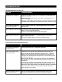
TROUBLESHOOTING . . . . . . . . . . . . . . . . . . . . . . . . . . . . . . . . . . . . . . . . . . . . . . . . . . . . . . . . . . . . . . . . . . . . . . . . . .71
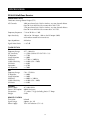
SPECIFICATIONS . . . . . . . . . . . . . . . . . . . . . . . . . . . . . . . . . . . . . . . . . . . . . . . . . . . . . . . . . . . . . . . . . . . . . . . . . . . . . .72
5
INTRODUCTION
Niles Audio has recognized the need for a simple to use, cost-effective multi-zone system that can provide years
of listening pleasure to music-lovers. Our engineering and product development departments have joined
forces to produce an innovative multi-zone receiver that incorporates six separate zones of amplifier power, a
built-in AM/FM tuner, and connections for three additional audio-source components.
The ZR-4630 MultiZone Receiver is the multi-zone solution for which you have been asking. It allows you to
combine keypad modules with infrared sensors and hand-held remotes for total control of your home entertainment system, providing "one-touch" system-wide control.
Now everyone in the household can be happy: One person can listen to the CD player in a bedroom, while
another simultaneously listens to the radio by the pool. At the same time a third person can listen to DSS music
in the den. In addition, the ZR-4630's source-component IR control is custom-programmable to provide intuitive operation for a wide range of source components.
ZR-4630 MultiZone Receiver
6
FEATURES AND BENEFITS
Multi-zone/Multi-source
The ZR-4630 MultiZone Receiver incorporates matrix preamplifier technology to provide as many as three
source components and the built-in tuner to six listening zones simultaneously. Finally, Dad can relax to the
sound of his favorite music in the den while the kids are listening to their favorite music by the pool.
12-Channel 30W Amplifier for Six Zones of Stereo Sound
The ZR-4630 MultiZone Receiver is an integrated solution for multi-zone applications. Six built-in 30W stereo
amplifiers provide clear and dynamic sound for six zoned areas.
Built-in AM/FM Tuner
The ZR-4630 includes a built-in AM/FM tuner that is available to all zones as one of four source-component selections. This high-quality tuner is programmable with 10 preset AM and 10 preset FM stations, and includes direct
station access.
Central Intelligence
The design approach of the ZR-4630 MultiZone Receiver is a radical departure from that of traditional programmable keypad-controlled multi-zone systems. Instead of redundantly programming each of the individual keypads with IR commands, all IR commands are programmed and stored in the ZR-4630. The Solo™ Master
Keypad Module, Numeric™ Accessory Keypad Module, and Niles IR Sensors connect to the receiver for complete system control.
Total system cost is now dramatically reduced due to shorter programming time and the low cost of the modular
keypads located in each zone.
Quick and Easy Programming with PC Archiving
Manual programming is made fast and easy via push buttons and LED visual prompts that lead you step-by-step
through the programming process. Additionally, all system programming can be archived on your PC for back-up
and for use with pre-designed systems with Niles ZR-4630 Archiving software.
One-Touch Operation with Source Component Power Synchronization
One touch of a Master Key or Source Button initiates the ZR-4630 MultiZone Receiver to perform a sequence
of IR commands for complete automation of your distributed A/V system.
Sync Inputs provided by the ZR-4630 sense if the connected source components are ON or OFF. Power commands for these source components are issued only if the source components are actually OFF, turning them
on correctly, every time. The proper input for the source component is then selected and a programmed
sequence of IR commands are issued (i.e., play or favorite station).
A complex mix of various brand audio/video components can be operated with ease and simplicity when using
the ZR-4630.
Elegant and Intuitive User Interfaces
The Solo™ Master Keypad Module - The Solo™ Master Keypad Module is an elegant, single gang, complete control solution for the ZR-4630. Custom labeled Master Keys provide complete system activation and source selection, while a complete set of cursor keys provides basic source transport and menu control.
The Numeric™ Accessory Keypad Module - The Numeric™ Accessory Keypad Module can be included along
with the Solo™ Master Keypad Module in any or all zones. This combination provides direct access to discs,
tracks, stations, and channels when operating DSS receivers, CD/DVD changers, and the built-in AM/FM tuner.
7
FEATURES AND BENEFITS
The R-4 Remote - The R-4 Remote provides system control via an ergonomic hand-held IR remote control.
Zones that have been installed with Niles IR Sensors can take advantage of the R-4 Remote, providing system
control from anywhere in the room.
System-Wide Operation
The ZR-4630 MultiZone Receiver incorporates system-wide control to activate all zones to a particular source
component. An ALL OFF command is also included for complete system shutdown from any zone in the system.
Zone Linking
The ZR-4630 MultiZone Receiver incorporates Zone-Linking to allow a grouping of zones to be controlled as
a single zone. Turn-On, Source selection, Paging and Turn-Off all work in unison, yet each zone has independent Volume adjustment and Muting.
Paging Input for Telephone Systems
A paging input is provided for telephone systems equipped with a paging output. Audio sensing is utilized to
detect the paging signal. Source components currently playing in the various zones are interrupted, enabling
the paging signal to play through. If a zone is off during a page, it turns on, enabling the paging signal to play
through. Front-panel switches are provided to disable this paging feature in any zones where it is not required.
12V Control Output
A control output connector provides a constant 12V DC trigger signal the moment any zone is activated. This
signal can be interfaced to Voltage Triggered AC Power Strips (i.e., Niles AC-3) for the automation of source
components that can only be activated via switched AC outlets.
Expandable for Larger MultiZone Systems
Up to three ZR-4630’s can be combined in a single system, providing 18 zones. Source components are connected to all receivers, splitting their audio signals utilizing RCA Y-adapters or Niles AVDA-3 Distribution Amplifiers.
Program Memory Protection
The ZR-4630 MultiZone Receiver utilizes non-volatile memory for storage of its programming. This safeguards
against accidental loss of the programming for the entire life of the product.
8
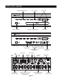
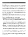
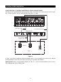
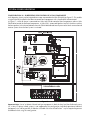
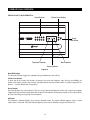
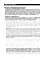
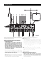
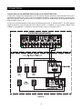
PARTS GUIDE (ZR-4630)
LED Zone ON/OFF Indicator
Main Power Switch
Zone Label Slots
Tuner Controls
Removable Programming Cover
Sensor for Capturing
IR Commands
Tuner Display
Zone All On/Page
Enable Switches
Programming Controls
and Indicators
Sync
Inputs
Audio
Inputs
Keypad Inputs
Paging
Input
Individual Zone
Preamplifier Output
DB-9 Computer
Interface
Flasher Outputs
System
Expansion
IR
Input
Gold plated, dual banana plug
spaced, five-way speaker
binding posts
12V Control
Output
Fixed/Variable Preamplifier
Adjustment Switch
Figure 1
9
Tuner Antenna
Inputs
Removable
Power Cord Socket
PARTS GUIDE (ZR-4630)
LED Zone ON/OFF Indicators
Provides individual ON/OFF indication for each zone.
Keypad Inputs
Six female RJ-45 jacks for the connection of the
IntelliPad Ci® Master Keypad Modules.
Zone Label Slots
Coined slot for placing included zone labels for easy
identification.
System Expansion
Two female RJ-45 jacks for connecting multiple
receivers together in larger multi-zone systems.
Tuner Controls
Radio station up/down, radio station preset, and AM/FM
band shift buttons for tuner control.
Flasher Outputs
Three 3.5mm jacks provide an output connection for
IRC-2P MicroFlashers™, one for each connected source
component. A fourth is designed for the IRC-1P
FloodFlasher™.
Tuner Display
Displays the currently selected radio station and
reception mode (stereo vs. mono).
IR Input
A single 3.5mm jack provides an input connection for
IR commands sent from a Home Theater. These IR
commands are used for control of source components
shared with a ZR-4630.
Removable Programming Cover
Conceals installer only programming controls during
normal operation.
Main Power Switch
Turns the main power to the receiver ON and OFF.
Note: Equipment is not completely disconnected from
the main power source when power switch is in the
OFF position.
12V Control Output
A single 3.5mm jack provides a 12V DC trigger signal
for use with voltage-triggered AC power strips (i.e.,
Niles AC-3) to control source components requiring
activation via a switched AC outlet.
Sensor for IR Capture
IR sensor for capturing IR commands for control of the
connected source components.
Tuner Antenna Inputs
A female coaxial F-connector and two spring-loaded
bare-wire jacks provide connection to the included
FM and AM antennas.
Programming Controls and Indicators
Push buttons and LED prompts for system and IR programming.
Audio Inputs
Three pairs of stereo RCA jacks provide input connections for source components.
Zone ALL ON/PAGE Enable Switches
Individual DIP switches enable or disable System
Wide All ON commands and the paging feature.
Individual Zone Preamplifier Outputs
Six pairs of stereo RCA jacks provide output connections
for external amplifiers used instead of, or in conjunction
with, the ZR-4630 built-in amplifiers.
DB-9 Computer Interface
Laptop connection enabling program configuration
backup/downloading using ZR-4630 archiving software.
Fixed/Variable Preamplifier Output
Adjustment Switch
Two-position switches, included for zones 4, 5, and 6,
provide the ability to change the individual preamplifier outputs to either a variable or a fixed signal.
Sync Inputs
Video and voltage sensing RCA Sync Inputs 2, 3, and 4
are for detecting when a source component is on/off for
reliable system activation. The HT mini plug Sync Input
senses voltage for determining the on/off status of a Home
Theater sharing source components with the ZR-4630.
Speaker Connector
Gold plated, dual banana plug spaced, five-way
speaker binding posts provide connection to speakers
in the listening zones.
Paging Input
A mono RCA input for a paging signal from a telephone system.
10
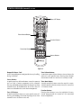
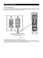
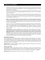
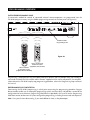
PARTS GUIDE (R-4 REMOTE) INCLUDED
Zone OFF Button
Zone Volume Buttons
Function Buttons
Zone Mute Button
Source Buttons
Figure 2
Removable Power Cord
An IEC removable power cord provides for easy handling
during installation.
Zone Volume Buttons
A continuous press of these buttons raises or lowers the
volume in your specific zone. Pressing these buttons
also restores sound in a zone that is currently muted.
Source Buttons
A quick tap of any of these buttons causes the zone to
turn on and a source component to be selected.
Pressing and holding these buttons for longer than three
seconds causes all enabled zones to turn on. Also, all
zones are selected to the same source component.
Zone Mute Button
A quick tap of this button mutes the sound in a zone.
A quick tap of this button restores sound in a zone that
is currently muted.
Function Buttons
Pressing these buttons issues the individual IR commands programmed for control of the connected
source components.
Zone OFF Button
A quick tap of this button turns your specific zone off.
Pressing and holding this button for longer than three
seconds causes all zones to turn off.
11
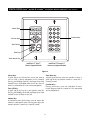
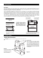
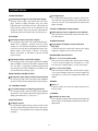
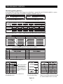
PARTS GUIDE (SOLO™ MASTER & NUMERIC™ ACCESSORY KEYPAD MODULES) SOLD SEPARATELY
Master Keys
Function Keys
Function Keys
Zone Off Key
Mute Key
Zone Volume Key
IntelliPad Ci® Solo™
Master Keypad Module
IntelliPad Ci® Numeric™
Accessory Keypad Module
Figure 3
Master Keys
A quick tap of any of these keys causes the zone to
turn on and a source component to be selected.
Pressing and holding these keys for longer than three
seconds causes all enabled zones to turn on. Also, all
zones are selected to the same source-component.
Zone Mute Key
A quick tap of this key mutes the sound in a zone. A
quick tap of this key restores sound in a zone that is
currently muted.
Function Keys
Pressing these keys issues the individual IR commands programmed for control of the connected
source components.
Zone OFF Key
A quick tap of this key turns your specific zone off.
Pressing and holding this button for longer than three
seconds causes all zones to turn off.
Volume Keys
A continuous press of these keys raises or lowers the
volume in your specific zone. Pressing these keys also
restores sound in a zone that is currently muted.
12
DS00287CMY-1_ZR-4630.qxp
9/13/05
5:22 PM
Page 13
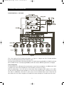
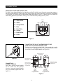
SYSTEM CONFIGURATIONS
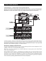
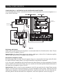
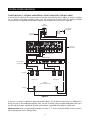
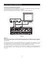
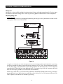
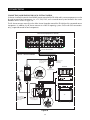
CONFIGURATION 1 - SIX ZONES
Figure 4
This is the simplest of the ZR-4630 configurations (see Figure 4). It depicts one Niles ZR-4630 MultiZone
Receiver installed to provide sound to six listening zones.
Each zone consists of one room with one pair of speakers. One Solo™ Master Keypad Module is included in each zone
for user control. Numeric™ Accessory Keypad Modules and an IR Sensor are added to specific zones as an option.
Source Components
The ZR-4630 has RCA audio inputs for connecting three external source components. In addition to the builtin AM/FM Tuner, three source components can be selected by each of the six zones.
With this configuration, a user in one zone can listen to one source component while another user in a different zone listens to a different source component (i.e. the CD can be selected in Zone 1 while the tuner is selected in Zone 2). Additionally, each of the six zones can be set to an individual volume level. If more than one
zone chooses the same source component, IR control of that source component is shared between the zones.
13
SYSTEM CONFIGURATIONS
Keypads and IR Sensors
Keypads and IR sensors enable the user to control the Niles ZR-4630 MultiZone Receiver and its connected source
components. Source component IR commands are programmed into the Niles ZR-4630 MultiZone Receiver. These
commands are then triggered when the user presses a keypad button or issues a Niles IR command to an IR sensor.
Each zone on the ZR-4630 has a corresponding RJ-45 keypad connector that is used to connect one Solo™ Master
Keypad Module. Each Solo™ Master Keypad Module can be mated with one optional Numeric™ Accessory Keypad
Module using an included jumper cable (see Connections, Figure 33). The Solo™ Master Keypad Module connects
to the ZR-4630 with a “home run” of four-pair twisted cable, terminated with RJ-45 connectors.
An IR Sensor can be included in any zone and connects directly to the Solo™ Master Keypad Module (see the
Installation section of this manual for more details). A three-wire to RJ-45 adapter is available from Niles (see
Accessories) for IR Sensors installed with two-conductor shielded cable rather than four-pair twisted cable.
Adding an IR Sensor enables the Niles R-4 Remote to control the ZR-4630 and the connected source components. In addition, a source component’s actual IR commands (i.e., provided by the component’s original
remote control or a learning remote control programmed with these IR commands) can be used with the IR
sensor to control the source components.
Important Note: The ZR-4630 does not provide individual operation of identical source components when
using a source component’s factory remote through an IR Sensor (see Identical Source Components on page 41
for more details).
Source-Component Automation
There are two methods of controlling the power ON/OFF of the source components.
1. Synchronized IR - In Figure 4, the DSS receiver’s power ON/OFF is synchronized via a video signal connected to the ZR-4630. When the Master Key/Source Button for the DSS is pressed, the ZR-4630 checks for a
video signal at the Sync Input corresponding to the DSS. The ZR-4630 issues the power command to turn
the DSS ON only when there is no video signal present and the DSS is OFF.
When the Off Key/Button is pressed in a zone, the ZR-4630 checks to see if any other zones are ON (including the Home Theater Zone sharing sources). The power command for turning the DSS OFF is issued only if
that zone is the last zone turning OFF in entire system and there is a video signal present at the Sync Input
corresponding to the DSS.
Important Note: RCA Sync Inputs also can detect 12V for use with Niles external sensing devices, (i.e. the LS-1
Light Sensor and the APC-2 Current Sensing Device). See Connections on page 44 for more information.
2. Latching Power - In Figure 4, AC power to the DVD and CD changer is turned on and off via the switched
AC outlets of a Niles AC-3. The AC-3 is activated by the 12V Control Output from the ZR-4630 when any
one of the six zones is ON (including the Home Theater Zone sharing sources). The built-in AM/FM tuner is
also turned ON when one of the six zones is ON.
Each Master Key on the Solo™ Master Keypad Module and its respective source component are programmable
with a sequence of IR commands. Commands included in the sequence are typically the Play or Channel commands to start a source playing or to select a particular music or radio station after the source has been selected.
Flasher Outputs
Niles MF1 MicroFlashers™ connect to the numbered flasher outputs on the rear panel of the Niles ZR-4630
MultiZone Receiver. Flashers send IR commands to the individual source components for control. A IRB-1 HighOutput IR Flasher can be connected to the Flasher output labeled ALL to control more than one source component.
Speakers
Each zone has “home run” speaker cables from the location of the speakers for connection to the built-in zone amplifier.
Connections are made to the ZR-4630’s speaker output terminals utilizing gold plated, dual banana plug spaced, fiveway speaker binding posts.
14
SYSTEM CONFIGURATIONS
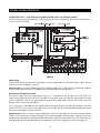
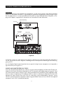
CONFIGURATION 2 – ADDING ZONES USING MULTIPLE ZR-4630’S
More than one ZR-4630 can be used if the system requires more than six zones. A maximum of three ZR-4630’s,
providing up to 18 zones, can be combined to create a larger multi-zone/multi-source system. One ZR-4630 is
designated as the Master and the others as Slaves (see Installation Settings on page 58 for more details).
Designated
as the Master
Designated
as Slave #1
Figure 5
As shown in Figure 5, a four-pair twisted cable connecting the expansion ports of the two ZR-4630’s facilitates
communication between them. This communication enables all zones provided by both ZR-4630’s to obtain
control of the shared-source components (which are always connected to the Master). Also, system-wide
commands can be issued from any zone (i.e. All Zones ON/OFF).
Sharing Source Components with Two ZR-4630’s
The Niles ZR-4630 MultiZone Receivers (Figure 5) share the audio signal from the source components via RCA
Y-adapters. Audio signals are connected to both ZR-4630’s.
Note: When sharing source components with a third ZR-4630 (for an 18-zone system) or with a Home Theater
system, refer to Configuration 3.
Source-component control (Figure 6) is accomplished via the programming in the master ZR-4630. All Slave
ZR-4630’s in the system must be left unprogrammed except for tuner preset stations. All Flasher and Sync Input
connections for the shared source components are made to the Master ZR-4630. Keypad/Source Button
commands and zone On/Off status are communicated to the Master ZR-4630 using the System Expansion
In/Out connections, providing coordinated control of all source-components.
15
SYSTEM CONFIGURATIONS
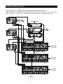
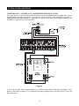
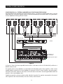
CONFIGURATION 3 – DISTRIBUTING SOURCE-COMPONENT AUDIO SIGNALS
When sharing source components with three ZR-4630’s (see Figure 6) or two ZR-4630’s and a Home Theater
system (see Figure 7), a Niles AVDA-3 Audio/Video Distribution Amplifier is required for each source.
Designated
as the Master
Designated
as Slave #1
Designated
as Slave #2
Figure 6
16
SYSTEM CONFIGURATIONS
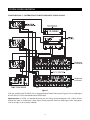
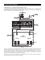
CONFIGURATION 3 – DISTRIBUTING SOURCE-COMPONENT AUDIO SIGNALS
Designated
as the Master
Designated
as Slave #1
Figure 7
If you are installing three ZR-4630’s with an integrated Home Theater Zone (refer to Figure 8), the cascade output
on each AVDA-3 may be connected to the third ZR-4630.
Important Note: An AVDA-3 is required whenever you are sharing source components with a Home Theater
receiver that shorts its audio inputs. (Some Home Theater receivers short their audio inputs when their power
is off or the input is not currently selected.)
17
SYSTEM CONFIGURATIONS
CONFIGURATION 4 – INTEGRATING AN IR-CONTROLLED HOME THEATER
An IR-controlled Home Theater surround-sound receiver can be integrated to share source components in a
system with the ZR-4630.
Niles MF1
MicroFlashers
Niles MF1
MicroFlasher
MSU250
WS100
Figure 8
Distributing Audio Signals
Audio signals for the shared source components are connected to both the ZR-4630 and the Home Theater
receiver using RCA Y-adapters (Figure 8).
Important Note: If the Home Theater Receiver has shorting audio inputs, a Niles AVDA-3 Distribution Amplifier
must be used in place of the RCA Y-adapters (refer to Figure 7).
Shared Source Component Control
The Flasher output from the Home Theater IR repeater (Figure 8) is connected to the IR Input of the ZR-4630.
The Home Theater IR remote control is now able to control the shared source components.
A 12V Sync signal is provided from the Home Theater to the Home Theater Sync Input to provide the ZR-4630
with the On/Off status of the Home Theater. This status enables the ZR-4630 to provide coordinated control of
the shared source component's power ON/OFF.
Important Note: When issuing the source component’s actual IR commands from the Home Theater remote
control, all IR commands are passed through to all source-component flasher outputs. Identical brand and
model source components cannot be operated individually using these commands. (For more information on
controlling identical brand and model source components, refer to the Operation Overview on page 32.)
18
SYSTEM CONFIGURATIONS
CONFIGURATION 5 – INTEGRATING A HOME THEATER USING AN INTELLICONTROL
A Home Theater system controlled by a Niles IntelliControl can be integrated to share source components in
a system with the ZR-4630.
Figure 9
Audio Signals
Audio signals for the shared source components are connected to both the ZR-4630 and the Home Theater
receiver using RCA Y-adapters (Figure 9).
Important Note: If the Home Theater receiver has shorting audio inputs, a Niles AVDA-3 Distribution Amplifier
must be used in place of the RCA Y-adapters (for more information see configuration 3).
Shared Source-Component Control
The Flasher output from the IntelliControl® (Figure 9) is connected to the IR Input of the ZR-4630. The
IntelliControl, programmed with Niles R-4 Remote IR commands, now can automate and control the shared
source-components. Niles R-4 IR commands are taught to the IntelliControl using the R-4 Remote itself (see
Programming Overview for more details).
A 12V Sync signal is provided from the IntelliControl to the Home Theater Sync Input to provide the ZR-4630
with the ON/OFF status of the Home Theater. This status enables the ZR-4630 to provide coordinated control
of the source component's power ON/OFF.
Important Note: When issuing the source component’s actual IR commands from the Home Theater Remote
Control, all IR commands are passed through to all source-component flasher outputs. Identical brand and
model source components cannot be operated individually using these commands. (For more information on
controlling identical brand and model source components, refer to the Operation Overview on page 32.)
19
SYSTEM CONFIGURATIONS
CONFIGURATION 6 – MULTIPLE SOLO™ MASTER KEYPAD MODULES IN A ZONE
The single zone of a Niles ZR-4630 MultiZone Receiver can be expanded to contain multiple Solo™ Master
Keypad Modules providing control from many locations within the zone. A Niles IntelliPad® Ci Expander™ is
required to connect multiple keypads in a single zone. A maximum of five Solo™ Master Keypad Modules can be
included in a single zone using two Expanders.
Figure 10
In Figure 10, two Solo™ Master Keypad Modules are installed on either side of a bed. When connected, all keypads in a zone work in tandem (i.e., all control the same zone and display the same Zone ON/OFF, Mute, and
Input Select Status.)
20
SYSTEM CONFIGURATIONS
CONFIGURATION 7 – MULTIPLE LISTENING AREAS IN A ZONE
A single zone of the ZR-4630 can be set up to contain more than one listening area (i.e., an adjacent living
room and dining room). This configuration is chosen when the speakers in the zone are not required to be
played at separate volume levels or to be on/off separately.
Figure 11
In Figure 11, speaker cable is connected to the speaker outputs of Zone 3 and then parallel connected to the
speakers in both the living room and the dining room. A Solo™ Master Keypad Module is located in each area.
A Niles IntelliPad® Ci Expander™ is required to connect the two Solo™ Master Keypad Modules in a single zone.
When connected, all keypads in a zone work in tandem with one another (i.e., all control the same zone and
display the same Zone ON/OFF, Mute, and Input Select Status).
A maximum of two pairs of 8 ohm speakers can be added to a zone in this manner. An external amplifier is
required for zones with more than two pairs of speakers.
21
SYSTEM CONFIGURATIONS
CONFIGURATION 8 – EXTERNAL AMPLIFIER IN A ZONE FOR MORE POWER
Each zone of the ZR-4630 provides RCA preamplifier output connections for the connection of external amplifiers. External amplifiers can be used to provide more power in a zone.
RCA Audio Cables
Four-Pair Twisted Cable
Niles SI-245
C KO
IN FR
U
E D S EN
AR
NO
T
K
T
NO
R
SO
E D S EN
AR
K
R
SO
IN FR
Two-Conductor
Speaker Cable
CK O
U
Speakers
Keypad
ZONE 3
Figure 12
In Figure 12, an external amplifier has been connected to zone 3. Using an amplifier with more than the 30W per
13 in large rooms and outdoors.
channel provides the zone with more volume Fig.
for listening
Important Note: When using preamplifier outputs for zones 4, 5, and 6, the fixed/variable switch must be in
the variable position for this configuration.
22
SYSTEM CONFIGURATIONS
CONFIGURATION 9 – EXTERNAL AMPLIFIER IN A ZONE FOR MULTIPLE LISTENING AREAS
A zone of the ZR-4630 can be set up to contain more than one listening area by adding an external amplifier
(i.e., an adjacent living room and dining room area). This configuration is chosen when the speakers included
in the zone are not required to be played at separate volume levels or to be ON/OFF separately.
Niles
Ci Expander
Unswitched
AC Outlet
Power
Supply
Four-Pair
Twisted Cable
Four-Pair
Twisted Cable
RCA Audio Cables
Niles SI-245
RE D S EN
Living Room
OCK O U
IN F R
A
KN
OCK O U
A
R E D S EN
KN
T
IN F R
IN F R
RE D S EN
T
T
A
KN
R
SO
O CK O U
T
RE D S EN
R
SO
A
KN
R
SO
Speakers
R
SO
IN F R
Two-Conductor
Speaker Cable
O CK O U
Dining Room
ZONE 3
(Living / Dining Room)
Keypads
Figure 13
Fig. 14
In Figure 13, an external amplifier has been connected to Zone 3. This enables the zone to have an additional listening area with its own dedicated amplifier. Now, with the ZR-4630’s internal amplifier dedicated to one listening area and the external amplifier to the other, greater power is provided to the speakers in both areas.
Important Note: When using preamplifier outputs for zones 4, 5, and 6, the fixed/variable switch must be in
the variable position for this configuration.
23
SYSTEM CONFIGURATIONS
CONFIGURATION 10 – EXTERNAL AMPLIFIER IN A ZONE FOR MULTIPLE ROOMS
The preamplifier output connectors on the ZR-4630 for zones 4, 5 and 6 have a fixed/variable setting. Using the
fixed setting with an external amplifier enables a zone to be divided up into individual rooms using conventional Niles Impedance Matching Volume Controls.
CK O
CK O
C KO
U
NO
C KO
U
K
E D S EN
AR
NO
INF R
ED SEN
AR
K
CK O
K
U
Speaker Cable
ED S EN
AR
NO
T
NO
INF R
ED SEN
AR
K
U
T
NO
INF R
E D S EN
AR
INF R
INF R
K
T
U
T
NO
T
INF R
INF R
E D S EN
AR
T
T
T
K
U
R
SO
C KO
R
SO
NO
Terrace
R
SO
ED SEN
AR
K
R
SO
U
Walk-In Closet
R
SO
C KO
R
SO
NO
Master Bathroom
R
SO
ED S EN
AR
K
R
SO
INF R
Master Bedroom
CK O
U
Wired in
Parallel
Niles SI-245
ZONE 6
RCA Audio Cables
Keypad Connections
Preamplifier set
to Fixed Mode
Variable Speaker Output
Figure 14
In Figure 14, Zone 6 has been expanded into four rooms. Each room can be On/Off individually and be set at
different volume levels.
The speakers for the master bedroom are connectedFig.
to the15
ZR-4630’s internal zone amplifier. A Solo™ Master
Keypad Module is placed in the master bedroom for control of ON/OFF, source selection, and source operation for the entire zone. However, the volume and mute buttons on the Solo™ Master Keypad Module affect the
speakers in the master bedroom only.
Impedance-magnifying volume controls enable individual control of the speakers connected to the external
zone amplifier in the master bathroom, the walk-in closet, and the terrace.
24
SYSTEM CONFIGURATIONS
CONFIGURATION 11 – SYSTEM PAGING AND EXTERNAL TELEPHONE SYSTEM
A Paging Input connection on the rear panel of the ZR-4630 provides a connection for the paging output signal of popular telephone systems for voice paging through the speakers in the listening zones (see Figure 15). Paging volume level
can be adjusted by the ZR-4630 (see Installation Settings on page 59 for more information).
System
Telephones
Telephone
Control Unit
PAGE OUTPUT
Figure 15
A Niles AVDA-3 (see Figure 16) is required when connecting a telephone system to more than one ZR-4630
in larger systems.
Fig. 16
System
Telephones
Telephone
Control Unit
PAGE OUTPUT
Niles AVDA-3
Distribution Amplifier
Figure 16
25
SYSTEM CONFIGURATIONS
CONFIGURATION 12 – IR REPEATING FOR CONTROL OF LOCAL COMPONENTS
An IR Repeating System can be integrated into a room connected to the Niles ZR-4630 (see Figure 17). This enables
a single IR Sensor (installed in that room) to control local components with a hand-held IR remote control.
In Figure 17, a Niles IR Sensor is connected to a Niles MSU250 for control of local components and to a Niles
ZR-4630 for control of distributed components. A Niles SPK-1 Automated Speaker Level A-B Switcher switches
the front speakers in the Master Bedroom from the ZR-4630 distributed sound system to the local surround-sound
receiver system when the local system is activated.
1 = STATUS
2 = DATA
3 = GROUND
4 = 12V DC
3-30V
AC/DC
STATUS
IN
MSU-250
Figure 17
Important Note: Use of an identical brand and type component in both the local and the distributed system
(i.e., a Sony CD player in both systems) is not supported by this configuration. Individual operation of identical
components may not be possible. IR blockers included with Niles MicroFlashers™ may be required to prevent
IR feedback when using this configuration.
26
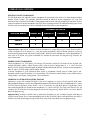
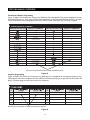
COMPONENT COMPATIBILITY
Infrared Command Compatibility
IR control testing was conducted on many equipment brands to determine their compatibility with the ZR-4630.
Typical A/V source components (i.e., CD, DVD, DSS, Cable Boxes, etc.) from each brand were chosen for the
test. All brands listed below passed the test.
Adcom
APEX
B&K
Denon
Echo Star
Escient
Go Video
Harman Kardon
Hitachi
Hughes
JVC
Kenwood
Krell
Lexicon
Lightolier
Magnavox
Marantz
McIntosh
Meridian
Mitsubishi
Motorola
NAD Electronics
Nakamichi
Niles
Onkyo
Panasonic
Parasound
Philips
Pioneer
RCA
Rotel
Samsung
Scientific Atlanta
Sharp
Sherwood
Sony
Technics
Toshiba
Yamaha
Zenith
Important Note: Use this list only as a starting point. All the components for every brand listed were not available at the time of testing. To avoid unforeseen incompatibilities, Niles recommends always testing components
you have not yet used with a ZR-4630 prior to specifying them in your installation.
Testing for a Possible IR Command Conflict
When using a Niles IRB-1 High Output Flasher, there are rare instances when the same IR command will operate more than one source component. This prevents the proper operation of another IR-controlled component
when the two are installed in the same system because the press of a single remote button causes both components to respond. Rare as this situation is, when working with unfamiliar equipment or two products that you
have never combined in the same system, it is advisable to first test how these components interact with each
other.
To test for this type of conflict, take all the remotes in the system (following the example above with six components, you would need to test all six remotes) and issue every command you will be programming in the keypads.
Expose all components to each command, and make sure that only the appropriate component responds.
Solving the IR Command Conflict if Present
Remember that conflicts of this nature are rare. However, if you find yourself in this situation, contact the manufacturer to ask if they are aware of the problem and if they have a solution. Perhaps they now have a different remote, or there may be a chip upgrade for the product.
If the manufacturers do not have a solution, the problem may be resolved by using a Niles MicroFlasher™
instead of IRB-1 High Output Flasher. In cases where neither solution works, advise the client of the situation
and explain that it is necessary to substitute the component.
27
SOURCE POWER SYNCHRONIZATION
WHAT IS SOURCE-POWER SYNCHRONIZATION?
The ZR-4630 has been designed to keep track of the ON/OFF condition of the three source components connected
to the system. This enables source components that utilize the same IR command for ON and OFF to be automated.
For this feature to function as designed, you need “synchronization (sync)” between the ZR-4630 and source
components that utilize the same IR command for ON and OFF. This assures the users of the system that the
ZR-4630 will always issue Power commands correctly when they press a Master Key or the Off Key.
Source Power Sync makes it possible for the user to always have a source component turn ON when they need
it on and to always have all the components turn OFF when they turn the System off.
Source Components that require Power Synchronization
Source components that utilize the same IR command for ON and OFF need to be synchronized. The power
button for these source components sends the same IR command to turn the source components ON if they are
OFF, and to turn them OFF if they are ON. It is necessary to “synchronize” these source components with the
ZR-4630 so it knows not to send an ON command if the source components are already ON (if it did, the source
components would turn OFF, which is not the desired result). Conversely, synchronization keeps the ZR-4630
from issuing a “power” command when the OFF Key is pressed, if the source components are already OFF.
The ZR-4630 has three Sync Inputs for each of the source components. It allows synchronization via voltage and video
signals. (see Choosing a Synchronization Method on page 29 for more information on how to synchronize components).
Source Components that do not require Synchronization
Two types of components do not require synchronization: those with separate ON and OFF IR commands, and
those with “latching power.”
Source Components with separate ON/OFF IR commands
There are source components that are included with and respond to separate ON and OFF IR commands.
Synchronization is not required for them. When power commands are programmed as separate ON and OFF,
the ZR-4630 will issue ON commands only if Sync is not present. Separate OFF commands for source components are always issued when the last zone turns OFF regardless of sync status.
Source Components with “Latching Power”
Some source components, like CD players and tape decks, are usually plugged into the switched AC outlet of
the preamplifier/receiver that they are installed with. These components simply turn ON when the system’s
receiver/preamplifier turns ON, meaning that they “latch” into an ON or OFF state and do not need an IR command to turn ON or OFF.
Because they turn ON as soon as there is power on their AC cord, once the preamplifier/receiver is turned on,
these components will be turned on as well. They do not need individual synchronization.
Since the ZR-4630 does not provide a switched AC outlet, the 12V Control Output connected to a Voltage
Triggered AC Power Strip (i.e., Niles AC-3) provides perfect control of latching source components (see C
onfiguration 1 in the Systems Configurations section of this manual for more information).
28
SOURCE POWER SYNCHRONIZATION
CHOOSING A SYNCHRONIZATION METHOD
Once you establish that all source components in the system have compatible IR commands, the next step is
to choose the appropriate Sync Method for each component.
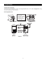
There are two ways to detect when a component is ON or OFF: Video or Voltage Sync.
TV
DSS
DIGITAL
AUDIO VIDEO
L R
PHONE
Video Input
RCA Y-Adapter
Splitting Video Output
Figure 18
Video Sync
Video Sync is the easiest and most reliable method
synchronization. Most video sources have a video outFig.of19
put active only when the device is ON. This type of video output provides an excellent method for component
synchronization.
The ZR-4630 has three source-synchronization connections that can accept either 12V or video input. In Figure
18, the video output of a DSS is connected to both a TV and the corresponding Sync Input for the DSS using an
RCA Y-adapter. Picture quality will be unaffected due to the high impedance of the Sync Input.
If the source component has two video outputs, the need for an RCA Y-adapter is eliminated. Simply connect
the first video output to its normal system destination, and the second video output will be dedicated for the
Sync Input.
29
SOURCE POWER SYNCHRONIZATION
Voltage Sync
Voltage Sync is also a reliable method of synchronization if chosen and implemented correctly. The Sync Inputs
can detect the control out voltage from a Niles Signal Sensing product interfaced to the source component.
Obtaining Voltage Sync
Current Sensing
Current Sensing synchronizes a component by detecting the changes in the AC power draw that occurs with
a component when it turns ON and OFF.
AUDIO
L
DIGITAL
CD CHANGER
R
Back
Niles APC-2
Front
Figure 19
In Figure 19, a Niles APC-2 Current Sensing Switch senses the change in power consumption of a CD changFig.it 20
er when it is turned ON. When it senses that change,
outputs a 12V DC signal. The synchronized CD changer’s AC power plug is connected to the current sensing outlet on the APC-2. The APC-2’s 12V DC output is
connected to the ZR-4630’s Sync Input dedicated to the CD changer using a Niles 10’ accessory cable with
bare wire to mini-plug (FG00724, see Accessories for more details).
When using a Niles APC-2, a minimum change of 30W is required for reliable current sensing. If the component does not have a 30W change in current draw when turning ON (i.e., DSS receivers and most VCRs
and CD players), consider the last method, Light Sensing.
30
SOURCE POWER SYNCHRONIZATION
Light Sensing
Using a light sensor (LS-1) to synchronize your components is usually your last choice, simply because the other
choices are more reliable. The Niles LS-1 Light Sensor can synchronize a component by sensing changes in light.
The 12V output of the LS-1 is then connected to the ZR-4630’s Sync Input dedicated for that component, a miniplug to RCA adapter is required for this connection (see Connections for more information).
Audio Out
Light Sensing Probe
placed over an LED
DSS
Unswitched
AC Outlet
Niles LS-1
Power Supply
Figure 20
Fig.changes
21
In Figure 20, a Niles LS-1 Light Sensor senses
in brightness of a DSS’s front panel LED and outputs a
12V DC signal when the LED is brightest. A blocking cover is used to prevent ambient light from falsely triggering the LS-1.
An unused optical digital output located on the rear panel of a digital source component can also provide a
light source for Sync using the LS-1.
SOURCE AND HOME THEATER SYNC STATUS
Sync status (the presence or absence of a valid sync signal) of source components and the Home Theater associated with the Master ZR-4630 are displayed on the LEDs located in the hidden programming panel. These
LEDs illuminate only while a valid sync signal is being received by the ZR-4630 during normal operation mode.
Source 2, Source 3, and Source 4 LEDs represent Source 2, Source 3, and Source 4 respectively. The Tuner LED
represents the Home Theater. These status LEDs are used during system troubleshooting. Manually turning
ON/OFF synchronized source components and the integrated Home Theater will turn ON/OFF the respective
component’s status LED if synchronized correctly.
31
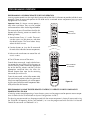
OPERATIONAL OVERVIEW
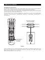
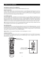
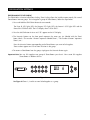
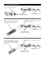
MASTER KEYS/SOURCE BUTTONS
The Master Keys available on the Solo™ Master Keypad Module and the Source Buttons on the hand-held R-4
Remote (Figure 21) provide “one-touch activation” of the ZR-4630 and source components.
The Master Keys on the Solo™ Master Keypad Module are equipped with back lighting LEDs for indicating Zone
ON/OFF, Zone Mute, and Zone Input Selection status.
The Source Buttons on the R-4 Remote correspond to the Master Keys on the Solo™ Master Keypad Module
(Master Key 1 = Tuner, Master Key 2 = Source Button 2, Master Key 3 = Source Button 3, and Master Key 4 =
Source Button 4).
Master Keys on the Solo™
Master Keypad Module
Master Key #1
Master Key #2
Master Key #3
Master Key #4
Source Buttons on
the hand-held
R-4 Remote
Figure 21
The four available Master Keys and their corresponding Source Buttons are individually programmable. Once
programmed, they operate the system identically in each zone. Master Keys on the Solo™ Master Keypad
Module should be labeled the same in each zone.
32
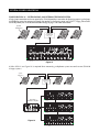
OPERATIONAL OVERVIEW
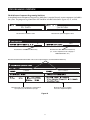
Master Key/Source Button Events
When you press a Master Key on a Solo™ Master Keypad Module or a Source Button on the hand held R-4
Remote, as many as four events occur.
The first event is factory programmed and activates the zone which you are located. The second event is factory programmed and selects the proper source input corresponding to the Master Key or Source Button pressed
(1 = Tuner, 2 = Input 2, 3 = Input 3, 4 = Input 4).
There are two installer programmable events available for Master Keys and Source Buttons 2, 3, and 4: Event 3
- the Source ON Event, and Event 4 - the Sequence Event.
Because there is no power command required for the ZR-4630’s internal tuner, Master Key 1 and the Tuner
Source Button are programmable only with the Sequence Event.
Master Key/
Source Button
Event 1
(Zone ON)
Event 2
(Input)
Event 3
(Source ON)
Event 4
(Sequence)
Master Key 1 or
Tuner Source Button
Turns Zone On
(Factory
Programmed)
Selects Tuner
(Factory
Programmed)
Not Available
Installer
Programmed
Master Key 2 or
Source Button 2
Turns Zone On
(Factory
Programmed)
Selects Input 2
(Factory
Programmed)
Installer
Programmed
Installer
Programmed
Master Key 3 or
Source Button 3
Turns Zone On
(Factory
Programmed)
Selects Input 3
(Factory
Programmed)
Installer
Programmed
Installer
Programmed
Master Key 4 or
Source Button 4
Turns Zone On
(Factory
Programmed)
Selects Input 4
(Factory
Programmed)
Installer
Programmed
Installer
Programmed
Event 1
Event 3
This event turns a ZONE ON when a Master Key or a
Source Button is pressed. Pressing and holding a Master
Key/Source Button turns all zones on to that source (the
zone must be enabled via a DIP switch, see Installation
Settings for more details). When a zone is on, the selected Master Key on the Solo™ illuminates green.
This event turns ON IR-activated source components (i.e.,
DSS, VCR) when a Master Key/Source Button is pressed.
The Source ON event occurs only for Master Keys/Source
Buttons 2, 3, and 4. Power commands for each Master
Key/Source Button are programmed individually and
occur conditionally, synchronized via the corresponding Sync Inputs.
Event 2
This event selects the proper input for the Master
Key/Source Button pressed. The source selected for
Master Key 1 on the Solo™ Master Keypad Module, and
the Tuner Source Button on the R-4 Remote, is the internal Tuner. Master Keys/ Source Buttons 2, 3, and 4 are for
the external audio inputs respectively. These inputs are
selected every time a Master Key or a Source Button is
pressed or pressed and held.
Event 4
This event issues IR commands and programmed time
delays. It is executed last and occurs every time a
Master Key/Source Button is pressed. Play, group, file, or
channel commands for an associated source component
typically are included in the sequence. The sequence for
Master Keys/Source Buttons 2, 3, and 4 can be programmed with the IR commands taught to their respective
function keys along with programmed time delays. The
sequence for the Tuner Source Key can be programmed
with the tuner’s direct access or preset access commands.
33
OPERATIONAL OVERVIEW
MASTER KEY/SOURCE BUTTON OPERATION
The Master Key/Source Buttons have three methods for operating the system.
Single Zone Operation
The first method, a quick tap of a Master Key/Source Button in a zone (holding the Key/Button for less than three
seconds), causes only that zone to turn ON. The Master Key quickly tapped illuminates GREEN after the zone
turns ON. A zone turns ON to its last volume setting. A maximum turn ON volume can be programmed into
the ZR-4630 (see Installation Settings for more information).
System Wide Operation
The second method, a press and hold of a Master Key/Source Button in any zone (holding the Key/Button for more
than three seconds), turns all zones ON that are set to ALL ON/Page enabled (this setting is made via front panel
programming DIP switches, set individually for each zone). All zones enabled for ALL ON/PAGE, select the source
associated with the Master Key/Source Button pressed and held, and that same Master Key LED illuminates
GREEN. The ALL ON volume can be adjusted with the ZR-4630 (see Installation Settings for more information).
Note: When the Tuner Master Key (master #1) is pressed and held, the radio station currently selected in that zone
will be selected by all zones when using multiple ZR-4630's in a system.
Zone linked Operation
The third Method, a press of a Master Key/Source Button that is part of a Zone-Linked group of zones, causes the
linked Zones/Rooms to turn ON to the selected Source. Each Zone/Room turns ON to its individual programmed
Turn On Volume level. Each Zone/Rom has independent Volume control. Changing a Source in any of the linked
Zones/Rooms changes the Source in all the linked Zone/Rooms.
Inportant Note: Only one group of Zones/Rooms can be linked together in a chassis.
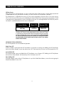
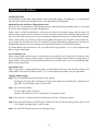
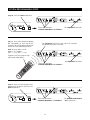
OFF KEY/OFF BUTTON
The OFF Key/Button included on both the Solo™ Master Keypad Module and the hand-held R-4 Remote provide “one-touch” system deactivation. When you are finished listening in a zone, a single press of the OFF Key/
Button deactivates the zone.
Off Button on the
hand-held R-4 Remote
Off Key on the Solo™
Master Keypad Module
Figure 22
34
OPERATIONAL OVERVIEW
OFF Key Events
When you press the OFF Key/Button, as many as two events occur. The first event is factory programmed and
is responsible for turning the zone or all zones OFF every time the OFF Key/Button is pressed.
The second event is responsible for turning OFF the source components and only occurs if the zone turning
OFF was the last zone ON in the system (including the Home Theater Zone sharing source components). There
is no programming required for this event. The programming that was accomplished for the Master Key Source
ON events is reversed to deactivate the source components.
Master Key/
Source Button
Event 1
(Zone OFF)
Event 2
(Source OFF)
OFF Key
Factory
Programmed
Programmed
Automatically
The Zone OFF Event is factory programmed and the Source OFF Event
is automatically programmed to reverse the programming of the Master
Key/Source Buttons that turn the source components ON. IR commands
are issued conditionally based on System and Component power
synchronization and the on/off status of other zones in the system
and the Home Theater.
OFF KEY/BUTTON OPERATION
The OFF Key/Button has two methods of operation.
Single Zone OFF
The first method, a quick tap of the OFF Key/Button in a zone that is currently ON (holding the OFF Key/Button
for less than three seconds), causes the zone to turn OFF. The Master Key LED that was illuminated turns OFF.
System Wide OFF
The second method, a press and hold of the OFF Key/Button, turns all zones OFF (holding the OFF Key/Button
for more than three seconds). All Master Key LEDs in all zones turn OFF.
Zone Linking OFF
The third method, a press of the OFF Key/Button in any of the linked Zones/Rooms, causes the entire group of
linked Zones/Rooms to turn OFF.
35
OPERATIONAL OVERVIEW
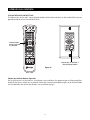
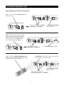
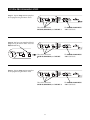
VOLUME KEYS/VOLUME BUTTONS
The Volume Keys on the Solo™ Master Keypad Module and the Volume Buttons on the hand-held R-4 Remote
provide control of volume for individual zones.
Volume Buttons
on the hand-held
R-4 Remote
Volume Keys on the Solo™
Master Keypad Module
Figure 23
Volume Keys/Volume Buttons Operation
Pressing the Volume + or the Volume - Keys/Buttons raises and lowers the speaker output and the preamplifier
output for the zone in which you are located. (Zones that have their preamplifier outputs set to the fixed mode
are not affected by the volume keys/buttons, see Installation Settings.)
36
OPERATIONAL OVERVIEW
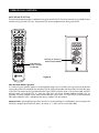
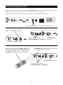
MUTE KEY/MUTE BUTTON
The Mute Key/Button provides a method of turning the sound ON/OFF for a brief moment in an individual zone
without turning the zone OFF (this also prevents the source component from being turned OFF).
Mute Key on the Solo™
Master Keypad Module
Mute Button on
on the hand-held
R-4 Remote
Figure 24
Mute Key/Mute Button Operation
In a zone using the speaker output or the preamplifier output set to variable, pressing the Mute Key/Button
mutes and unmutes the sound for that zone only. The ZR-4630 still considers the zone to be ON while the zone
is MUTED. The Master Key for the selected source lights GREEN while the zone is ON and unmuted, and RED
while the zone ON and MUTED. If a zone has more than one Master Keypad Module installed using an
Expander, all Master Keypads in that zone indicate identical system status (i.e., Zone ON/OFF, Zone Mute and
Zone Input Selection status), and operate the zone in tandem with one another.
Important Note: A preamplifier output for a zone that is set to fixed output is unaffected by the mute command
and always outputs sound while the zone is on (zones 4, 5, and 6 can be set to fixed mode).
37
OPERATIONAL OVERVIEW
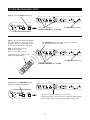
FUNCTION KEYS/BUTTONS
The Solo™ Master Keypad Module, the Numeric™ Accessory Keypad Module, and the hand-held R-4 Remote
include various function keys for control of the built-in tuner and the connected source components. Figure 26
illustrates the available function keys for all of the control devices.
Function Keys on the Solo™ Master Keypad
Module, the Numeric™ Accessory Module and
the hand-held R-4 Remote
Figure 25
Function Key/Button Operation for Connected Source Components
After the Master Key/Source Button for a source component has been pressed, the ZR-4630 activates a zone
and selects that source component. The individual function keys/buttons in that zone will now issue the IR commands that have been programmed for the source component you selected.
38
OPERATIONAL OVERVIEW
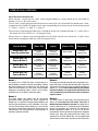
Function Key/Button Operation for the Built-in Tuner
The commands for operation of the built-in tuner from the function keys/Buttons are pre-programmed. Figure
27 depicts the available commands for the tuner, their function key/button location, and a description of their
action on the tuner.
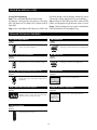
Pre-Programmed Tuner Commands
Key
*
Arrow Up
Arrow Down
Arrow Right
Arrow Left
Surf +
Surf AM
FM
1
2
3
4
5
6
7
8
9
0
+
Fav
Figure 26
Command
AM/FM
Next Preset
Last Preset
Seek Up
Seek Down
Next Preset
Last Preset
AM
FM
1
2
3
4
5
6
7
8
9
0
Last Preset
Next Preset
Preset Call
Shifts tuning band between AM and FM
Scrolls the 20 preset stations, 10 AM and 10 FM
Next tunable station is selected in the currently
chosen tuning band, AM or FM
Scrolls the 20 preset stations, 10 AM and 10 FM
Direct access to AM and FM
Number commands for accessing stations directly
or by preset number
Scrolls the 20 preset stations, 10 AM and 10 FM
Enables number commands to call preset stations
After the Tuner Master Key/Source button has been selected in a zone, the pre-programmed tuner commands
become available from their designated function keys/buttons. Radio stations can be accessed from preset
memory, or directly.
39
OPERATIONAL OVERVIEW
FRONT PANEL TUNER OPERATION
Preset Buttons
Station Scan Buttons
Band
Shift Button
Frequency Indicator
Band Indicator
Stereo Indicator
Figure 27
Band-Shift Button
The Band Shift Button toggles the selected tuning band between AM and FM.
Station Scan Buttons
A quick tap of the Station Scan Buttons increments the tuner one frequency step. Pressing and holding the
Station Scan Buttons searches the currently selected band for the next tunable station (+ searches upward in frequency, – searches downward in frequency).
Preset Buttons
The Preset Buttons have two functions. The first is to call up memorized preset stations with a quick tap (supports
10 presets for the AM band and for 10 for the FM band). The second is to store preset stations in the memory. Refer
to Tuner Preset Programming Steps for more details.
Indicators
The Frequency Indicator displays the currently selected station. The Stereo Indicator appears when a stereo
radio station is received. The Band Indicator displays the currently selected tuning band (AM or FM).
40
OPERATIONAL OVERVIEW
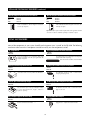
IDENTICAL SOURCE COMPONENTS
The ZR-4630 routes the individual source component IR commands with which it has been programmed to
specific Flasher Outputs. This provides individual control of identical source components (i.e., two DSS
receivers of the same brand and model). These programmed IR commands are routed to the individual Flasher
Outputs based on the source components for which they were programmed. The table below designates where
IR commands are routed when a zone is selected to one of the three source components.
FLASHER OUTPUTS
Selected Source
Flasher ALL
Flasher 2
Source 2
X
X
Source 3
X
Source 4
X
Flasher 3
Flasher 4
X
X
Important Note: Operation of an identical source component is not possible using its actual IR commands in
a zone installed with an IR Sensor. (i.e., using the source component’s original remote control or a learning
remote control programmed with these IR commands). Identical source components can be operated from a
zone with an IR Sensor using Niles hand-held R-4 Remote IR commands (see Programming Overview for
more information).
SHARED SOURCE COMPONENTS
Source components (i.e., DVD player, CD changer, DSS receiver) used with a ZR-4630, can be “Shared” with
multiple ZR-4630’s and/or a Home Theater system (refer to System Configurations 2, 3, 4, and 5 for more
details). The ZR-4630 has been designed to provide coordinated control of these “shared” source components
from all zones, of all ZR-4630’s and the Home Theater.
A Source Component in a ZR-4630 Multi-Zone System is considered “shared” when its audio signal is connected to more than one ZR-4630 or if it is connected to a ZR-4630 and a Home Theater system (refer to System
Configuration 2 and System Configuration 3 for more details).
OPERATING A SYSTEM WITH MULTIPLE ZR-4630’S
Operating a system with multiple ZR-4630’s is the same as operating a system with only one ZR-4630. Solo™
Master Keypad Modules in each zone independently operate the zone to which they are dedicated to (i.e., zone
ON/OFF, Volume Up/Down, Mute). When a user in a zone from any ZR-4630, presses a key/button, the IR
commands required for the shared source components (i.e., Power ON/OFF, Play, Stop, and Channel Up), are
issued by the ZR-4630 that has been programmed. See the Programming Section of this manual for specific
details on programming.
Important Note: The built-in AM/FM tuners in each of the ZR-4630’s, are not “sharable” between each other or
with the Home Theater. The six zones provided by each of the ZR-4630’s listen to and control their own built-in
AM/FM tuner (refer to the Programming section of this manual for more details on tuner programming).
41
OPERATIONAL OVERVIEW
OPERATING A SYSTEM INTEGRATED WITH A HOME THEATER
Operation from the Stereo Zones Provided by the ZR-4630
User operation from the zones provided by ZR-4630’s, are not affected when integrating a Home Theater to
share source components (see System Configurations 4 & 5). Solo™ Master Keypad Modules in each zone
independently operate the zone to which they are dedicated (i.e., Zone ON/OFF, Volume Up/Down, Mute).
When a user in a zone from any ZR-4630, presses a Key/Button, the IR commands required for the shared
source components (i.e., power ON/OFF, Play, Stop, and Channel Up), are issued by the ZR-4630 that has
been programmed. See the Programming Section of this manual for specific details on programming.
Operation from the Home Theater Zone
A Home Theater can be integrated to share source components with a ZR-4630 using one of three methods. How the Home Theater will operate depends on which method is chosen. The three methods of integration are listed below, along with a description of the Home Theater operation they provide.
Method 1. Integrated Home Theater using 12V Home Theater Sync and IR Repeating
The Home Theater IR Remote (programmed with the actual IR commands of the shared source components) sends IR commands to the shared source components via the IR Input located on the rear panel
of the ZR-4630. This enables control of the shared source components for users in the Home Theater. All
IR commands for shared source components are passed through to all four of the Flasher Outputs on the
rear panel of the ZR-4630. Only discrete power ON and transport commands for the shared source components should be issued.
Important Note: Because all of the actual IR commands for shared components are passed through to
all the Flashers Outputs simultaneously, identical source components cannot be operated individually
with this method. Also, when using this method, reliable activation of Shared Source Components that
use a single IR command for power ON/OFF is not possible. (Refer to Method 2 for operating identical
shared source components and Components with a single IR command for power ON/OFF.)
When the Home Theater turns ON, it provides a 12V Status signal that is connected to the Home Theater Sync
Input on the rear panel of the ZR-4630. This provides the ON/OFF status of the Home Theater to the ZR-4630.
The moment a valid Home Theater Sync signal is present at the ZR-4630, the ZR-4630’s 12V Control
Output sends a turn-on trigger for a Voltage-Triggered AC Power Strip (i.e., Niles AC-3), activating latching source components.
When the Home Theater is turned OFF, the ZR-4630 checks itself and any other ZR-4630’s in the system to see if any zones are still ON. If all zones are OFF, the 12V Control Output shuts OFF, turning OFF
the latching source components. Power OFF IR commands for turning OFF the IR controlled shared
source components are also issued.
Method 2. Integrated Home Theater using 12V Home Theater Sync and Niles R-4 Commands
The Home Theater IR Remote (programmed with the Niles R-4 IR commands) sends IR commands to the
ZR-4630 via the IR Input located on the rear panel. This enables control of the shared source components
for users in the Home Theater.
All the actual IR commands for shared source components are programmed into the ZR-4630. When a Niles
IR command is received, the corresponding programmed-source IR commands are sent to the Flasher
Output dedicated to the shared source component that is selected (i.e., Source 2 = Flasher 2, Source 3 =
Flasher 3, Source 4 = Flasher 4). Identical source components can be individually operated with this method.
Important Note: shared source components that are unique in the system can have their actual IR commands programmed into the Home Theater remote and issued for simple IR repeating with this method.
42
OPERATIONAL OVERVIEW
When the Home Theater turns ON, it provides a 12V Status signal that is connected to the Home Theater
Sync Input on the rear panel of the ZR-4630. This 12V Status signal provides the ON/OFF status of the
Home Theater to the ZR-4630.
The moment a valid Home Theater Sync signal is present at the ZR-4630, the ZR-4630’s 12V Control
Output sends a turn-on trigger for a Voltage-Triggered AC Power Strip (i.e., Niles AC-3), activating latching source components.
When the Home Theater is turned OFF, the ZR-4630 checks itself and any other ZR-4630’s in the system to see if any zones are still ON. If all zones are OFF the 12V Control Output shuts OFF, turning OFF
the latching source components. Power OFF IR commands for turning OFF the IR controlled shared
source components are also issued.
Method 3. Integrated Home Theater without 12V Home Theater Sync and using Niles R-4 Commands
The Home Theater IR Remote (programmed with the Niles R-4 IR commands) sends IR commands to the
ZR-4630 via the IR Input located on the rear panel. This enables control of the shared source components
for users in the Home Theater.
All the actual IR commands for shared source components are programmed into the ZR-4630. When a
Niles IR command is received, the corresponding programmed source IR commands are sent to the
Flasher Output dedicated to the shared source component that is selected (i.e., Source 2 = Flasher 2,
Source 3 = Flasher 3, Source 4 = Flasher 4). Identical source components can be individually operated
with this method.
Important Note: shared source components that are unique in the system may have their actual IR commands programmed into the Home Theater remote and issued for simple IR repeating using this method.
When the Home Theater is turned OFF, the Home Theater Remote sends a Niles OFF command to the
ZR-4630. The ZR-4630 then checks all zones, for all ZR-4630’s in the system. If all zones are OFF, the
12V Control Output shuts OFF, turning OFF the latching source components. Power OFF IR commands
for the IR controlled shared source components, programmed into the ZR-4630 are also issued conditionally, based on the Source Sync status of the shared source components.
SYSTEM BUSY INDICATION
The ZR-4630 has a built-in System Busy Indication mode that is displayed on the Master Key LEDs of the Solo™
Master Keypad Module. If the ZR-4630 receives simultaneous commands from two different users and each
user is located in a separate zone, the user who does not get the expected response will be alerted by the Master
Key. That Master Key LED will quickly blink RED three times. The user who received the RED flashing Master
Key simply issues their command again.
Important Note: IR commands and delays included in the sequence for Master Keys also cause the system to indicate busy while they are being executed.
PAGING INDICATION
The ZR-4630 has a built-in Paging Indication mode that is displayed on a Master Key LED of the Solo™ Master
Keypad Module. If the ZR-4630 sends a page to a zone, the user is alerted by the Master Key. That Master Key LED
will blink slowly GREEN. The Master Key LED resumes its last state (ON or OFF) when the page is completed.
Important Note: Paging takes priority over all system functions until the page has ended.
43
INSTALLATION
PLACEMENT
Place the ZR-4630 on a flat, level surface such as a table or shelf, with its weight equally distributed on each of
its four feet. Placing the weight of the amplifier on the rear or front panel for even an instant will result in
damage to the amplifier's connectors and controls.
Like any high-fidelity component, the ZR-4630 will last much longer if it is given adequate ventilation for proper
cooling. When installing the ZR-4630 in a cabinet, be sure that the cabinet’s rear is open to receive fresh air in order
to provide proper cooling (see Figure 28). If the cabinet’s design does not accommodate an open rear, install two
small “boxer fans” to provide continuous airflow into and out of the cabinet (see Figure 29). Place the ZR-4630 so
it has at least seven inches of free air space above it. If the amplifier is located on a carpeted surface, place a board
under the amplifier’s feet. Do not block the ventilation holes on the top and bottom of the ZR-4630.
Boxer Fan (55 CFM)
directly centered 7” on
top of the ZR-4630.
Boxer Fan (55 CFM)
directly centered 2”
behind the ZR-4630.
Figure 28
Make sure that there is a minimum
of 7” of free air space above the
amplifier and 3” on each side for
proper ventilation.
CAUTION! When using lowimpedance speaker loads (less
than 8 ohms Nominal) refer to
Figure 29 for proper placement.
Figure 29
If the cabinet rear is not open to fresh air or if you’re using
low-impedance loads, install two “boxer fans” to provide
continuous air flow into and out of the cabinet.
Allow a minimum of 2” of depth
behind unit to accommodate cables
and connectors.
CONNECTIONS
Speaker Wire Connections
CAUTION! All speaker wire connections must be made with the amplifier OFF.
Banana Plugs
There are many types of banana plugs available.
Some are crimped onto the speaker wire and
some are soldered. Niles offers banana plugs that
have a quick-connect binding system for the
speaker wire included within the banana plug itself.
After the wire is attached, the banana plug is simply inserted into the hole at the end of the amplifier's speaker binding post. Dual banana plugs will fit
the binding posts.
Bare Wire
Unscrew the red or black plastic knobs and insert the bare
wire through the hole in the
post. Tighten the knob until the
wire is securely clamped.
Figure 30
44
CONNECTIONS
TERMINATING FOUR-PAIR TWISTED CABLE
The Solo™ Master Keypad Modules, the Expander, and the ZR-4630’s System Expansion connections require a
four-pair twisted cable with a one-to-one wiring configuration. To maintain consistency throughout all Intellipad
Ci installations, we recommend the color-coding pattern described in Figure 31. However, you may follow the
color-coding pattern of your choice, as long as it is used consistently throughout the system.
Pair 2
1 = Green/White
2 = Green
Pair 3
Pair 1
Pair 4
3 = Orange/White
4 = Blue
5 = Blue/White
1 2 3 4 5 6 7 8
6 = Orange
7 = Brown/White
8 = Brown
T568A
Figure 31
CONNECTING THE SOLO™ MASTER KEYPADS TO THE
HOME RUN OF FOUR-PAIR TWISTED CABLE
The home run of four-pair twisted cable is terminated with a male
RJ-45 connector and plugged into the rear panel jack labeled SYSTEM
on the Solo™ Master Keypad Module (see Figure 32).
RJ-45 Connector for
connection to
the ZR-4630
Figure 32
RJ-45 Connector
for connection to
IR Sensors
INPUT
IR SENSOR
CONNECTING
NUMERIC™ KEYPADS
Each Solo™ Master Keypad Module
can be mated with one optional
Numeric™ Accessory Keypad Module
using an included jumper cable (see
Figure 33).
RJ-45 Connector
for connection to
Numeric Accessory
Keypad Module
SYSTEM
ACCESSORY
KEYPADS
OUTPUT
Included
Jumper Cable
Solo™
Master
Keypad Module
Numeric™
Accessory
Keypad Module
Figure 33
45
RJ-45 Connector for
connection to Master
Keypad Module
CONNECTIONS
CONNECTING IR SENSORS
An IR sensor can be connected to a Solo™ Master Keypad Module with a CAT 5 cable. See Figure 34 for wiring
instructions employing T568A architecture.
Connecting IR Receivers
1 = Blue/White - 12V
2 = Green - DATA
3 = Orange/White - GROUND
4 = Green/White - EMPTY
5 = Blue/White - STATUS
6 = Orange - EMPTY
7 = Brown/White - EMPTY
8 = Brown - EMPTY
T568A
CAT 5 Cable
IR SENSOR
SYSTEM
KEYPAD
ACCESORY
WS-100
Solo Master
Figure 34
46
CONNECTIONS
10
11
1
2
3
4
5
6
7
8
9
12
10
Figure 37
10
13
14
1
15
SOURCE-COMPONENT POWER AND HOME THEATER
SYNCHRONIZATION SIGNALS
17
2.
Sync from
a Source
Component
2 Voltage
3
4
5
6
7
8 to
9 a
ZR-4630 Sync Input 11
When obtaining a 12V sync signal from a source component (refer to the Source Power Synchronization section10of
this manual for more information), a Niles Accessory Cable
(FG00724) connected to a Radio Shack 274-326 mini-plug
to male RCA adapter provides proper connection to any of
the three Source Sync Inputs.
1 Video Synchronization from a Source Component
1.
to a ZR-4630 Sync Input
2
3
4
5
6
7
8
9
An RCA Y-adapter is used to split the video output of a
source component for connection to one of the three
Source Sync Inputs of the ZR-4630 (2, 3, or 4). One side
of the RCA Y-adapter connects to the appropriate
1 Source
Sync Input and the other side connects to the intended
2
destination for the video signal (i.e., the video input of a
TV, receiver or RF modulator).
10
3 12V Home
4
7
8 Theater
9
Theater5 Sync6to Home
Sync Input
3.
The 12V Home Theater sync signal connects with a miniplug to the Home Theater Sync Input.
12
The need for an RCA Y-adapter can be avoided if your
video source has two video outputs.1 One video output
connects to a Source Sync Input and the other to the
2
3
intended destination of the video signal.
11
KEYPAD MODULES
4 Keypads5to Keypad
6
7 Inputs
8
9 for Zones 1-6
4.
Four-pair twisted cable, terminated with male RJ-45
plugs, connects the keypads to the zoned Keypad Inputs
(for more information on Terminating Four-Pair Twisted
Cable, refer to page 44).
Important Note: Source Sync Inputs are designed with
high-input impedances so as not to affect the quality of
the video signal when using an RCA Y-adapter.
12
16
47
13
14
15
16
17
1
10
1
CONNECTIONS
2
10
2
3
4
5
11
6
7
8
10
4
3
5
6
7
8
9
11
SYSTEM EXPANSION
4
3
4
1
11
1.
5 System
6
7Expansion
8
9 1 Input to System Expansion Output
5.
5
6
7
8cable,
9
Four-pair
twisted
terminated
with
male 5RJ-456 7
2
3
4
12
plugs, connects multiple ZR-4630's using the System
Expansion Input and Output
terminals. Connections are
10
made from the Input of one of the ZR-4630's to the
SOURCE-COMPONENT AUDIO SIGNALS
Output of another, and so on (for more information on
12
Terminating Four-Pair Twisted Cable, refer to page 44).
1. Audio Output of Source
11 Components to the ZR-4630
11
Male-to-male RCA Audio Cables connect the three exterIR FLASHERS 12
nal audio sources.
10
2
3
4
5
6
7
8
9
6 Low-Output
7
8
9
6.
Flasher to the Flasher Outputs
The mini-plug end of a Niles Low Output MicroFlasher™,
Model MF-1 (FG01019), connects into the Flasher
10
Outputs 2-4. The Micro-Flasher
portion is placed direct12
ly over the IR sensor of the corresponding source com3
4 (Source 52 for 6Flasher
7
8 2, 9Source 3 for Flasher,
ponent
Source 4 for Flasher 4) and adheres with the included
11
peel-back tape.
5
2
TELEPHONE PAGING
13
1.
6
14
13
7 High-Output
8
9
7.
Flasher to the Flasher Outputs
The mini-plug end of a Niles High Output Flasher, Model
IRB-1 (FG01023), connects
to the Flasher Output labeled
10
15 IRB-1 is strategically
16 positioned
17 to provide IR
ALL. The
transmission
to15all source components
with
14
16 and adheres
17
13
14
its included Velcro mounting system.
13
17
Zones 1-615(4-6 set to Variable 16
Mode)
Male-to-male RCA Audio Cables connect Zone Outputs
1-6 to an external amplifier for more power in a zone
(refer to System Configurations 8 & 9 for more details).
15
1.
16
Zones 4-6 Set to Fixed
Mode 17
Male-to-male RCA Audio Cables connect Zone Outputs
4-6 (set to fixed output mode) to an external amplifier for
more rooms in a zone (refer to Configuration 10 for more
details).
HOME THEATER CONTROL SYSTEM
10
6
7
8 IR9 Output of a Home Theater Control System to the IR In
8.
The mini-plug end of a Niles Accessory Cable (FG00724)
connects a Home Theater Control System to the IR Input.
11
13
16
12V15CONTROL SIGNALS
14
6
7
8
14
15
17
9 12V Control Output to a Voltage Triggered Device
9.
The mini-plug end of a Niles Accessory Cable (FG00724)
connects the 12V Control Output to the Trigger Input of a
voltage-activated
device (i.e.,
Niles AC-3).
13
14
15
16
SPEAKERS
16
1.
1.
10
15
15
17
1.
FM Dipole Antenna
The included FM Dipole
Antenna
16
17 connects to the female
75-Ohm coaxial connector labeled FM on the chassis.
The antenna is then positioned and mounted for proper
11
reception.
16
17
Zones 1-617
Connects speaker wires from the speakers placed in the
listening zones.
AC POWER
AM/FM ANTENNAS
14
14
14
1.
11
5
14
15 System to ZR-463016
Paging Output
of Telephone
11
Page Input
A male-to-male RCA Audio Cable connects the paging
output of a telephone system to the ZR-4630.
PREAMPLIFIER ZONE OUTPUTS
13
5
AM Loop Antenna
11
The included AM Loop Antenna connects with its barewire ends to the spring-loaded terminals labeled AM and
8
9 The antenna is then positioned and mounted for
GND.
proper
reception.
10
48
Removable AC Power Cord
The removable AC power cord (included with the ZR-4630)
connects to the removable power-cord socket and to an AC
power outlet.
17
15
9
CONNECTIONS
CONNECTING AN IR SENSOR FOR LOCAL SYSTEM CONTROL
IR Sensors installed in zones for hand-held IR remote control of the ZR-4630 and its source components can also
be used to control local components (i.e., a TV, DSS, DVD, and a surround-sound system located in the master
bedroom zone as shown in figure 38).
The IR Sensor connects normally to the Solo™ Master Keypad to control the ZR-4630 and its connected source
components. In addition, the IR Sensor connects to a local IR repeating system (DATA and GND connections
only), to provide control of local components.
Distributed Equipment Location
Four Pair Twisted Cable
Zone 6 – Master Bedroom
RJ-45 Connector
for connection to
IR Sensors
1 = STATUS
2 = DATA
Niles
WS100R
IR SENSOR
SYSTEM
ACCESSORY
KEYPADS
Solo™
Master
Keypad Module
3 = GROUND
4 = 12V DC
RJ-45 Connector for
connection to
the ZR-4630
RECEIVER
DIGITAL
AUDIO VIDEO
L R
1
DVD
2
FRONT
L
R
CD
CENTER
L
Video 2
R
Video 1
DVD
DIGITAL
AUDIO VIDEO
L R
DSS
DIGITAL
AUDIO VIDEO
L R
3-30V
AC/DC
STATUS
IN
TV
Two Conductor
Shielded Cable
(connect DATA and
GND only)
Niles MSU250
(provided for IR control
of local equipment)
Figure 38
49
Fig. 38
REAR
L
R
Video 3
PHONE
CONNECTIONS
CONNECTING AN A/B AMPLIFIER SWITCH FOR LOCAL SYSTEM SELECTION
A Niles SPK-1 Voltage Activated Speaker Level A/B Switcher connects to both the ZR-4630 and a local system
to provide sound from each system to the same speakers located in a single zone. The local system only connects to the speakers when the local system is turned on. The Niles ZR-4630 connects to the speakers by default
when the local system is off.
In Figure 39, the Zoned Speaker Output of the ZR-4630 connects to the "A" side of the SPK-1. The Main Speaker
Output of the local system connects to the "B" side of the SPK-1. In addition, a 12V DC power adapter (Niles
FG00665) is plugged into a switched AC outlet of the local system to activate the SPK-1.
Figure 39
50
PROGRAMMING OVERVIEW
INSTALLER PROGRAMMING PANEL
IR commands needed for control of connected external source-components are programmed into the
ZR-4630’s program memory using the hidden programming controls on the front panel (see figure 42).
Hidden Installer
Programming Panel
Figure 42
Source Components
IR Remote Control
(supplied by manufacturer)
Niles hand-held
R-4 Remote Control
(supplied with the ZR-4630)
Programming is accomplished using the hidden panels push buttons and LED prompts along with sending IR
commands with both the Niles remote and the remotes supplied with the source components. For complete
information on the ZR-4630’s step-by-step programming procedure, refer to the Programming Steps section of
this manual.
PROGRAMMING DOCUMENTATION
Documenting the ZR-4630’s programming is critical prior to executing the programming procedure. Program
documentation enables you to accomplish programming quickly and accurately, and provides a record of the
configuration for future reference. Programming Worksheets are provided in this manual (see the Programming
Worksheet section) to document all system configuration programming, including IR commands and sequences.
Note: Use a pencil when documenting. If you need additional sheets, make photocopies.
51
PROGRAMMING OVERVIEW
ZR-4630 Programming Worksheet
A completed Tuner and Zone Label Programming Worksheet is required for each ZR-4630 installed in a system.
The programming information that should be included is detailed in figure 43.
Mr. Smith
Joe Installer
Document the customer’s name.
Document the system designer’s name.
7
Kitchen
Patio
Jacuzzi
Exercise
Bedroom
Terrace
Document the Master, Slave 1, or Slave 2 setting. Document the Labels used for the Zone Label slots.
620
830
910
1010
1050
1070
1090
1110
1140
1160
93.9
94.9
96.5
100.7
102.3
103.5
104.7
105.1
106.5
107.9
Document the AM and FM Presets stored in the Tuner Memory.
FM
Fav
1
Document the Tuner Sequence.
There are DIP switches
on the front panel to
determine which zones
will be enabled to the
ALL-ON and PAGE features.
Check the ones that have been enabled to the
ALL-ON/PAGE feature.
Document the numeric value
for each volume setting.
Figure 43
52
Document the amplifier to which the preamp
outputs are connected, and the mode selected
(i.e., fixed or variable for zones 4, 5, and 6).
PROGRAMMING OVERVIEW
ZR-4630 Source-Component Programming Worksheet
A completed source-component Programming Worksheet is required for each source-component included in
the system. The programming information that should be included is detailed in figures 44, 45, and 46.
Mr. Smith
Joe Installer
Document the customer’s name.
Document the system designer’s name.
2
DVD
Document the number of the Master Key
5
Document the label used for the Master Key
(i.e., source component, music category, or
DSS/Radio Station, etc.)
PROGRAM FUNCTION KEY IR COMMANDS
Document the brand and model number of the source component that is associated with the Master Key
FUNCTION KEY/BUTTON
5
SOURCE IR COMMAND
SOURCE IR COMMAND
FUNCTION KEY/BUTTON
SOURCE IR COMMAND
PROGRAM FUNCTION KEY IR COMMANDS
FUNCTION KEY/BUTTON
SOURCE IR COMMAND
Denon
7
5
FUNCTION KEY/BUTTON
DVD-2800
7
7
PROGRAM FUNCTION KEY IR COMMANDS
FUNCTION KEY/BUTTON
SOURCE IR COMMAND
Document if the source-component is connected to a
sync input. If yes, document the sync type
FUNCTION KEY/BUTTON
SOURCE IR COMMAND
Document the type of activation
the source component requires
Figure 44
53
PROGRAMMING OVERVIEW
Function Keys/Buttons Programming
Figure 45 depicts the section of the Programming Worksheet that corresponds to the source-component function
key/button programming. Each programmed source component has one worksheet filled out specifying what particular IR commands have been programmed and to which function key/button they have been assigned.
5
PROGRAM FUNCTION KEY IR COMMANDS
FUNCTION KEY/BUTTON
5
SOURCE IR COMMAND
Play
Stop
Pause
Rewind
Fast Forward
Pause
FUNCTION KEY/BUTTON
PROGRAM FUNCTION KEY IR COMMANDS
FUNCTION KEY/BUTTON
NextIRChapter
SOURCE
COMMAND
Last Chapter
FUNCTION KEY/BUTTON
SOURCE IR COMMAND
1
2
3
4
5
6
7
SOURCE IR8COMMAND
9
0
Random
Next Chapter
Last Chapter
Document the IR commands in their function key/button locations
Figure 45
Sequence Programming
Figure 46 depicts the section of the Programming Worksheet that corresponds to the Sequence programming.
Each programmed source component has one worksheet filled out specifying what particular IR commands and
delays have been programmed to the Master Keys Sequence.
Play
Play
Document the IR Commands and Delays included in the Sequence
Figure 46
54
PROGRAMMING OVERVIEW
PROGRAMMING A LEARNING REMOTE FOR ZONE OPERATION
Learning remote controls can be taught the IR commands of the Niles R-4 Remote to provide individual zone
operation. These IR commands operate the ZR-4630 and its associated source components from any zone
equipped with an IR Sensor.
Important Note: IR Sensors cannot operate a
zone when used alone. They must be installed
and connected to a Solo™ Master Keypad Module.
The commands you will teach from the Niles R-4
Remote to the learning remote are stored in the
following buttons:
Learning
Remote Control
1. Source buttons Tuner, 2, 3, and 4. These activate the system, turn the zones on, and select
the desired source. The Tuner button always
selects the built-in tuner.
2. Function buttons to issue the IR commands
for each of the individual source components.
3. Volume and mute buttons to control the volume in a zone.
4. The Off button to turn off the zones.
To teach these commands, simply take the learning remote that you will be using in the zone, set
it to the learning mode, choose the appropriate
key on the learning remote, and then issue the
appropriate command from the Niles R-4
Remote. Repeat these steps for the remaining
commands you wish to use.
Niles hand-held
R-4 Remote
To test the commands, set the Niles remote aside,
take your learning remote, and try the commands.
If they were captured correctly, you will be operating the system and all the source components identically to the Niles R-4 Remote.
Figure 47
PROGRAMMING A HOME THEATER REMOTE CONTROL TO OPERATE SOURCE COMPONENTS
SHARED WITH A ZR-4630
A learning remote control operating a home theater system can be programmed to operate source components shared with the ZR-4630 (refer to System Configurations 4 and 5).
The learning remote control may be programmed with the source component's factory IR commands using
the ZR-4630's IR Repeating feature (see Method 1), or it can be programmed with the Niles R-4 Remote
Control IR commands (see Methods 2 & 3).
55
PROGRAMMING OVERVIEW
teach the Niles R-4 Remote Control IR commands to
the Home Theater learning remote, rather than the IR
commands from the remote controls included with
the shared source components.
Method #1– Controlling Shared Source Components
with IR Repeating and 12V Home Theater Status
When using IR Repeating, IR programming for the
source components can be accomplished by programming the actual IR commands from the source
component’s included remote control into the Home
Theater learning remote control. An IR output of the IR
repeating or control system for the Home Theater is
connected to the IR Input of the Master ZR-4630. All the
IR commands sent from the Home Theater are then
passed through to all IR Flashers connected to the ZR4630 for control of source components.
You teach the Home Theater learning remote control
the R-4 IR commands issued from Source Buttons 2, 3,
4, and all other commands (excluding Tuner, Volume
+, Volume –, Mute, and OFF). Sending a Niles Source
Button IR command from the Home Theater tells the
ZR-4630 receiver the Home Theater is turning on and
which source it is selecting. Synchronized source
components corresponding to the source button
pressed are then turned ON, if not already ON.
Finally, the ZR-4630 issues the sequence that is programmed for that source component.
Important Note: If you have source components that
require an IR command to be turned on and they are
not provided with a separate ON and a separate OFF
IR command from their included remote controls, or if
you have two or more shared source components that
are an identical brand and model, refer to Method #2.
After the Master ZR-4630 receives a Source Button IR
command and it knows which source is selected, it
will then issue the programmed IR commands for that
source component when function-key IR commands
are received from the Home Theater.
All the IR command programming of the Home Theater
learning remote control is done in the standard way
using the actual remote controls for the shared source
components, with one exception. The OFF IR command
for the shared source components is not taught to the
learning remote operating the home theater. Only the
ON IR commands are taught for the shared source components turned ON and OFF via IR commands. The OFF
IR commands for the shared source components are
programmed into the ZR-4630, which is responsible for
turning these components OFF when all ZR-4630 zones
and the home theater are OFF.
Identical shared source components are operated
individually using this method via the IR routing feature of the ZR-4630 (refer to Identical Source
Components in the Operational Overview Section).
Method #2 requires a 12V DC system status signal
provided from the Home Theater system to the Home
Theater Sync Input of the Master ZR-4630. This allows
the ZR-4630 to “know” whether the home theater is
actually ON or OFF and provide the source components’ OFF commands at the appropriate time.
Method #1 requires a 12V DC system status signal
provided from the Home Theater system to the Home
Theater Sync Input of the Master ZR-4630. This allows
the ZR-4630 to “know” whether the Home Theater is
actually ON or OFF and provide the source components’ OFF commands at the appropriate time.
The IR programming for the actual Home Theater
receiver/processor is not affected when sharing source
components with this method and is done in conjunction with the programming described.
Important Note: There is no need to teach the Niles
OFF command to the Home Theater learning remote
control when using Method #2. As in Method #1, when
the Home Theater turns off, the 12V signal is removed
from the ZR-4630 Receiver and it now “knows” that the
Home Theater turned off. It will then check if there are
any other zones on the ZR-4630 active before it turns
off the shared source components.
The IR programming for the actual Home Theater
receiver/processor is not affected when sharing source
components using this method and is done in conjunction with programming described.
Method #2 – Controlling Shared Source Components
with Niles R-4 Commands and 12V Home Theater Status
A second method of programming a Home Theater
remote control is available when the shared source
components are identical and/or they have a single
power ON/OFF IR command. With this method, you
56
PROGRAMMING OVERVIEW
Method #3 – Controlling Shared Source Components
with Niles R-4 Commands and without 12V Home
Theater Status
A third method of programming is available in situations
where a 12V DC status signal is not available from the
Home Theater. With this method, you must teach some
of the Niles R-4 Remote Control IR commands to the
Home Theater learning remote.
The minimum requirement is to program the learning
remote with Niles commands from Source Buttons 2, 3,
or 4, and the OFF Button IR commands. Whenever the
Master ZR-4630 receives a source-button IR command
from the Home Theater, it will turn on the source component, if needed, and it will also know that the Home
Theater Zone is turning on and what source component
is selected. Whenever the Master ZR-4630 receives an
OFF Button IR command from the Home Theater, it will
know that the Home Theater is turning OFF.
To operate the Shared Source Components follow the
criteria specified in Method #1 and Method #2, to
select the most appropriate way to operate for your
system. You can program the Home Theater's learning
remote with either the components' IR commands or
with Niles function button commands when using this
method.
Important Note: You must teach the Niles OFF IR
command to the Home Theater learning remote control and issue it every time you turn the Home Theater
off when using Method #3. When the OFF IR command is received by the ZR-4630 Receiver, it “knows”
that the Home Theater turned off. It will then check for
any active zones on the ZR-4630 before it turns off the
shared source components.
57
PROGRAMMING WORKSHEET
1
JOB TITLE
2
3
UNIT MODE AND ZONE LABELS (CHOOSE ONLY ONE:
o (A) MASTER
SYSTEM DESIGNER
A, B OR C)
1
2
3
4
5
6
7
8
9
10
11
12
13
14
15
16
17
18
o (B) SLAVE 1
o (C) SLAVE 2
4
TUNER PRESETS
AM
5
1 _______________
6 _______________
1 _______________
6 _______________
2 _______________
7 _______________
2 _______________
7 _______________
3 _______________
8 _______________
3 _______________
8 _______________
4 _______________
9 _______________
4 _______________
9 _______________
5 _______________
10 _______________
5 _______________
10 _______________
TUNER SEQUENCE
STEP
6
FM
TUNER COMMAND
STEP
1
6
2
7
3
8
4
9
5
10
7
ALL ON/PAGE
ZONE
1
2
3
4
5
6
ALL ON / PAGE
o
o
o
o
o
o
VOLUME SETTINGS
ON VOLUME ________
MAX VOLUME ________
TUNER COMMAND
8
PREAMP OUTPUTS
*Zones 1-3 are variable only.
AMP
FIXED/VARIABLE
1
*
*
*
2
3
PAGE VOLUME ________
4
Note: Volume Settings affect
all Zones.
5
6
o
o
o
/
/
/
o
o
o
PROGRAMMING WORKSHEET
1
JOB TITLE
2
3
UNIT MODE AND ZONE LABELS (CHOOSE ONLY ONE:
o (A) MASTER
SYSTEM DESIGNER
A, B OR C)
1
2
3
4
5
6
7
8
9
10
11
12
13
14
15
16
17
18
o (B) SLAVE 1
o (C) SLAVE 2
4
TUNER PRESETS
AM
5
1 _______________
6 _______________
1 _______________
6 _______________
2 _______________
7 _______________
2 _______________
7 _______________
3 _______________
8 _______________
3 _______________
8 _______________
4 _______________
9 _______________
4 _______________
9 _______________
5 _______________
10 _______________
5 _______________
10 _______________
TUNER SEQUENCE
STEP
6
FM
TUNER COMMAND
1
6
2
7
3
8
4
9
5
10
7
ALL ON/PAGE
ZONE
1
2
3
4
5
6
ALL ON / PAGE
o
o
o
o
o
o
TUNER COMMAND
STEP
VOLUME SETTINGS
ON VOLUME ________
MAX VOLUME ________
8
PREAMP OUTPUTS
*Zones 1-3 are variable only.
AMP
FIXED/VARIABLE
1_________________
*
*
*
2_________________
3_________________
PAGE VOLUME ________
4_________________
Note: Volume Settings affect
all Zones.
5_________________
6_________________
o
o
o
/
/
/
o
o
o
SOURCE COMPONENT
PROGRAMMING WORKSHEET
1
JOB TITLE
2
3
CHOOSE MASTER KEY
MASTER KEY LABEL: ____________________
MASTER KEY NUMBER (2, 3, 4): ___________
4
SYSTEM DESIGNER
PROGRAM SOURCE COMPONENT POWER
COMPONENT
BRAND: __________________________________
COMPONENT SYNC
o Yes
5
o No
POWER PROGRAMMING
If Yes, SYNC TYPE:
o Video o 12V
o Single “Power” IR Command
o Two Separate ON and OFF IR Commands
o Latching Power
PROGRAM FUNCTION KEY IR COMMANDS
FUNCTION KEY/BUTTON
Play
Stop
Pause
Rewind <<
FF>>
*
Arrow Up
Arrow Down
Arrow Right
Arrow Left
M
G
E
P
Surf +
Surf –
AM
6
MODEL: ____________________________
SOURCE IR COMMAND
FUNCTION KEY/BUTTON
FM
1
2
3
4
5
6
7
8
9
0
–
+
Random
Group
Disc
Fav
SOURCE IR COMMAND
PROGRAM SEQUENCE
STEP
SOURCE IR COMMAND
or DELAY
FUNCTION KEY/BUTTON or STEP
DELAY TIME
1
6
2
7
3
8
4
9
5
10
SOURCE IR COMMAND
or DELAY
FUNCTION KEY/BUTTON or
DELAY TIME
SOURCE COMPONENT
PROGRAMMING WORKSHEET
1
JOB TITLE
2
3
CHOOSE MASTER KEY
MASTER KEY NUMBER (2, 3, 4): ___________
4
SYSTEM DESIGNER
MASTER KEY LABEL: ____________________
PROGRAM SOURCE COMPONENT POWER
COMPONENT
BRAND: __________________________________
COMPONENT SYNC
o Yes
5
o No
POWER PROGRAMMING
If Yes, SYNC TYPE:
o Video o 12V
o Single “Power” IR Command
o Two Separate ON and OFF IR Commands
o Latching Power
PROGRAM FUNCTION KEY IR COMMANDS
FUNCTION KEY/BUTTON
Play
Stop
Pause
Rewind <<
FF>>
*
Arrow Up
Arrow Down
Arrow Right
Arrow Left
M
G
E
P
Surf +
Surf –
AM
6
MODEL: ___________________________
SOURCE IR COMMAND
FUNCTION KEY/BUTTON
FM
1
2
3
4
5
6
7
8
9
0
–
+
Random
Group
Disc
Fav
SOURCE IR COMMAND
PROGRAM SEQUENCE
STEP
SOURCE IR COMMAND
or DELAY
FUNCTION KEY/BUTTON or STEP
DELAY TIME
1
6
2
7
3
8
4
9
5
10
SOURCE IR COMMAND
or DELAY
FUNCTION KEY/BUTTON or
DELAY TIME
SOURCE COMPONENT
PROGRAMMING WORKSHEET
1
JOB TITLE
2
3
CHOOSE MASTER KEY
MASTER KEY LABEL:
____________________
MASTER KEY NUMBER (2, 3, 4): ___________
4
SYSTEM DESIGNER
PROGRAM SOURCE COMPONENT POWER
COMPONENT
BRAND: __________________________________
COMPONENT SYNC
o Yes
5
o No
POWER PROGRAMMING
If Yes, SYNC TYPE:
o Video o 12V
o Single “Power” IR Command
o Two Separate ON and OFF IR Commands
o Latching Power
PROGRAM FUNCTION KEY IR COMMANDS
FUNCTION KEY/BUTTON
Play
Stop
Pause
Rewind <<
FF>>
*
Arrow Up
Arrow Down
Arrow Right
Arrow Left
M
G
E
P
Surf +
Surf –
AM
6
MODEL: __________________________
SOURCE IR COMMAND
FUNCTION KEY/BUTTON
FM
1
2
3
4
5
6
7
8
9
0
–
+
Random
Group
Disc
Fav
SOURCE IR COMMAND
PROGRAM SEQUENCE
STEP
SOURCE IR COMMAND
or DELAY
FUNCTION KEY/BUTTON or STEP
DELAY TIME
1
6
2
7
3
8
4
9
5
10
SOURCE IR COMMAND
or DELAY
FUNCTION KEY/BUTTON or
DELAY TIME
INSTALLATION SETTINGS
ALL ON/PAGE DIP SWITCH SETTINGS
There are six All ON/PAGE switches located on the hidden
programming panel of the ZR-4630. Each of the ZR-4630's
zones has a corresponding numbered switch (see Figure 40).
The switches enable (Up) or disable (Down) the individual
zones from responding to ALL ON commands and incoming audio pages.
1 2 3 4 5 6
Up
Down
Note: A page will not play through a Zone that has been disabled if the zone is OFF. A page will play through any Zone
that is turned ON, even if the Dip Switch is set to the disabled position.
Figure 41
FIXED/VARIABLE PREAMPLIFIER SWITCH
Zones 4, 5, and 6 include a Fixed/Variable preamplifier switch (see Figure 41) located on the rear panel of the
ZR-4630. The switch for these zones is set to either Variable or Fixed depending on the configuration of the
speakers in the zone (see Configurations 8, 9, and 10 for more details).
PROGRAMMING MASTER/SLAVE MODE
The factory default mode of the ZR-4630 MultiZone Receiver is "Master," but it can also be programmed to
function as "Slave 1" or "Slave 2" in expanded systems (refer to System Configuration 2). To change the mode
of any unit, follow the steps below:
1. Turn the ZR-4630 OFF.
2. Depress the PROGRAM button.
3. Turn the ZR-4630 ON and keep the PROGRAM button depressed.
4. The ZR-4630 then displays a message on the LCD Display Panel for 2 seconds, identifying its version ("Ver X.XX").
5. The ZR-4630 then displays a new mode, either "Master," Slave 1," or Slave 2.” Which mode is selected
depends on the last setting (i.e., if the last mode was of "Master," it will display "Slave 1.” If last the mode was
"Slave 1,” it will display "Slave 2.” And if the last mode was "Slave 2," it will display "Master").
6. Release the PROGRAM button. Unit is now set to a new mode.
7. Repeat Steps 1 through 6 until the ZR-4630 is in the desired mode.
INSTALLING ZONE LABELS
Each ZR-4630 is included with pre-printed Zone/Room
Labels that are designed to be placed in the Zone Label Slots
(see Figure 42) to identify the names of each of six zones.
To install these labels follow the steps below:
BEDROOM
1. Remove the label chosen for Zone 1 from the included
Room/Zone Labels.
2. Affix the label in Zone Label Slot #1.
3. Repeat steps 1 and 2 for Zones 2 through 6.
Figure 42
58
INSTALLATION SETTINGS
PROGRAMMING ZONE LINKING
The ZR-4630 has a feature called Zone Linking. Zone Linking allows the Installer to permanently link several
Zones/Rooms into one group. To Link together a group of Zones/Rooms, follow the steps below:
1. Press and Hold the PROGRAM button for two seconds.
The Enter IR LED lights RED, the Program LED lights RED, the Source 2 LED lights RED and the
Power/ON LED blinks RED. The LCD display shows “PGM SRC2”.
2. Press the AM/FM button 6 times until “ZL” appears on the LCD display.
3. The Numeric Buttons on the front panel represent the zones you just labeled with the Zone/
Room Labels. “The number 1 button” represents labeled Zone 1; “The number 2 button” represents
Zone 2, etc…
Press the Numeric Buttons corresponding to the Zones/Rooms you want to link together.
Zone numbers appear on LCD to show inclusion in the group.
4. To remove a Zone/Room from the group, simply press the Numeric Button again.
Important Note: You can link together one group of Zones/Rooms per chassis. You cannot link together
Zones/Rooms in different chassis.
ZL12 6
KITCHEN
Figure 43
See Figure 43 Zone 1, 2 and 6 are now linked together as a group.
59
INSTALLATION SETTINGS
VOLUME SETTINGS
The ZR-4630 has three useful volume features with customizable settings. The following is a list of the three
volume features along with their default values and a description of their purpose.
Maximum Turn ON and Source Change Volume Level
Maximum Turn ON and Source Change Volume prevents a zone from playing too loudly when it is first turned
on or if the zone changes the currently selected source.
When a zone is turned ON individually, it will always turn ON to its last volume setting unless the zone's last
volume setting is greater than the Maximum Turn ON and Source Change Volume Setting. When greater, the
zone will turn ON to the Maximum Turn ON and Source Change Volume level set in the ZR-4630's memory.
When a zone selects a new source, the volume setting does not change unless the zone’s current volume setting is greater than the Maximum Turn ON and Source Change Volume Setting. When greater, the zone will
change to the Maximum Turn ON and Source Change Volume level set in the ZR-4630's memory.
The factory default level for Maximum Turn ON and Source Change Volume is 45. It can be adjusted up or
down using the steps below.
ALL ON Volume Level
When a System Wide ON command is issued, zones that are turned OFF turn ON to the ALL ON Volume Level
set in the ZR-4630's memory (volume levels in zones that are already turned ON do not change during a
System Wide On command). The factory default level for ALL ON Volume level is 22. It can be adjusted up or
down using the steps below.
Page Volume Level
When a Page occurs, all zones produce the page at the Page Volume Level set in the ZR-4630's memory. The
factory default value for PAGE Volume Level is 35. It can be adjusted up or down using the steps below.
Changing Volume Settings
Step 1. Press and Hold the PROGRAM button for two seconds.
The Program LED lights RED, the Source 2 LED lights RED, Power/On LED Blinks RED, and the Enter IR
lights RED. The LCD display shows "PGM MODE"
Step 2. Press the AM/FM button.
The LCD display shows "MxVol 45"
"MxVol" is the Maximum Turn ON and Source Change Volume Level.
Step 3. Press the Tune + button to increase MxVol or press the Tune - to decrease MxVol.
Step 4. Press the AM/FM button or NEXT button to advance to the next volume-setting feature (shown in the
LCD Display) and repeat steps 3 and 4 for each.
Step 5. Press the PROGRAM button twice to exit programming.
60
SYSTEM PROGRAMMING STEPS
PROGRAMMING THE SOURCE COMPONENTS
Step 1 - Press and hold the PROGRAM button
for two seconds.
Three LEDs illuminate: ENTER IR,
PROGRAM, and SOURCE 2.
The POWER OR DISCRETE
“ON” LED blinks.
Step 2 - If Source Two is turned ON/OFF
with IR commands, go directly to Step 3.
If Source Two is not turned ON/OFF via
IR Commands, press the NEXT button
twice and move ahead to Step 8.
Two LEDs illuminate:
PROGRAM and SOURCE 2.
The IR COMMANDS LED blinks.
The ENTER IR LED blinks once after the IR command
is received and remains illuminated.
Step 3 - Teach the POWER OR DISCRETE “ON”
IR command from Source Two’s factory remote
control into the IR Sensor Window.
The POWER OR DISCRETE
“ON” LED blinks.
Three LEDs are illuminated:
ENTER IR, PROGRAM, and SOURCE 2.
61
SYSTEM PROGRAMMING STEPS
Step 4 - You can test the IR command by pressing the TEST IR button. The source will operate if the command has
been taught correctly. If it does not, reteach the IR command until the source operates.
Repositioning the remote control while reteaching can help to capture the command accurately.
Pressing the TEST IR button issues the last IR command taught.
Step 5 - Press the NEXT button once.
Three LEDs are illuminated:
ENTER IR, PROGRAM, and SOURCE 2.
The DISCRETE OFF
LED blinks.
The ENTER IR LED blinks once after the IR command
is received and remains illuminated.
Step 6 - If provided, teach the DISCRETE “OFF” IR command from Source Two’s factory remote control and test
it as described in Step 4. If Source Two does not have a
DISCRETE “OFF” IR command, go directly to Step 7.
The DISCRETE OFF LED blinks.
Three LEDs are illuminated:
ENTER IR, PROGRAM, and SOURCE 2.
62
SYSTEM PROGRAMMING STEPS
Step 7 - Press the NEXT button once.
Two LEDs illuminate:
PROGRAM and SOURCE 2.
The IR COMMANDS LED blinks.
The ENTER IR LED illuminates after the Niles Function
Key/Button command is received.
Step 8 - Issue a Niles Function Key/Button IR
command that will correspond to a Source
IR command into the IR Sensor Window.
The IR COMMANDS LED blinks.
Two LEDs are illuminated:
PROGRAM and SOURCE 2.
Step 9 - Teach the corresponding IR command
from Source Two’s factory remote control and
test it as described in Step 4. Repeat Steps 8 &
9 until all IR commands for Source Two have
been taught.
The ENTER IR LED turns off after the command is received.
The IR COMMANDS LED blinks.
Two LEDs are illuminated:
PROGRAM and SOURCE 2.
63
SYSTEM PROGRAMMING STEPS
Step 10 - Press the NEXT button once.
Three LEDs illuminate:
ENTER IR, PROGRAM and SOURCE 2.
Step 11 - Press each Function Key/Button
that corresponds to each step of the
Sequence you wish to program for Source
Two in the same order they will occur.
The SEQUENCE LED blinks.
The ENTER IR LED blinks once when the Function
Key/Button command is received.
Note: To insert delays, use the
Volume – or + buttons.
(Vol – = .5 sec., Vol + = 1 sec.)
Sequences can have up to 64 steps
(commands and/or delays).
Three LEDs illuminate:
ENTER IR, PROGRAM and SOURCE 2.
The SEQUENCE LED blinks.
Step 12 - You have now completed the
programming for Source Two. Press the
NEXT button once.
Three LEDs illuminate:
ENTER IR, PROGRAM, and SOURCE 3.
64
The POWER OR DISCRETE
“ON” LED blinks.
SYSTEM PROGRAMMING STEPS
Step 13 - Repeat Steps 2-11 to complete
the IR programming for Source Three.
Three LEDs illuminate:
ENTER IR, PROGRAM, and SOURCE 3.
The POWER OR DISCRETE
“ON” LED blinks.
Three LEDs illuminate:
ENTER IR, PROGRAM, and SOURCE
4.
The POWER OR DISCRETE
“ON” LED blinks.
Three LEDs illuminate:
ENTER IR, PROGRAM, and SOURCE 4.
The POWER OR DISCRETE
“ON” LED blinks.
Step 14 - You have now completed the IR
programming for Source Three. Press the
NEXT button once.
Step 15 - Repeat Steps 2-11 to complete
the IR programming for Source Four.
65
SYSTEM PROGRAMMING STEPS
Step 16 - Press the NEXT button once.
Three LEDs illuminate:
ENTER IR, PROGRAM, and TUNER.
Step 17 - Press each Function Key/Button
that corresponds to each step of the
Sequence you wish to program for the
Tuner in the same order they will occur.
The SEQUENCE LED blinks.
The ENTER IR LED blinks once when the Function
Key/Button command is received.
Note: To insert delays, use the
Volume – or + buttons.
(Vol – = .5 sec., Vol + = 1 sec.)
Sequences can have up to 64 steps
(commands and/or delays).
Three LEDs illuminate:
ENTER IR, PROGRAM, and TUNER.
The SEQUENCE LED blinks.
Step 18 - Press the PROGRAM button
once to exit programming mode.
All LEDs illuminate and then they all turn off.
(Some source lights may remain on if a source component or the
Home Theater are on after exiting the programming mode).
66
PROGRAM EDITING STEPS
The Enter IR light blinks.
SOURCE-POWER EDITING
These are the steps for editing the power ON/OFF
commands for the source components.
Step 1. Press and Hold the Program button.
Step 3. To test the command, press the TEST button. If
it does not operate the component as expected, teach
and test the command again until it does.
The Program LED lights RED, the Source 2 LED lights
RED, Power/On LED Blinks RED, and the Enter IR
lights RED.
Note: Repositioning the remote control when teaching the command can assist in capturing commands
accurately.
Edit Power for Source 2: Continue editing from Step 2.
Step 4. Tap the NEXT Button. The Power/ON LED
turns OFF and the OFF LED Blinks RED.
Edit Power for Source 3: Tap the NEXT button until
the Source 3 LED lights RED, the Power/On LED
Blinks RED, and the Enter IR lights RED. Continue editing from Step 2.
Step 5. If the component has a single power command
for both ON and OFF, press the NEXT button again and
continue your programming of the system.
or
If the component has a discrete ON and OFF command,
teach the discrete OFF command.
Edit Power for Source 4: Tap the NEXT button until
the Source 4 LED lights RED, the Power/On LED
Blinks RED, and the Enter IR lights RED. Continue programming from Step 2.
The Enter IR light blinks.
Step 2. If the component has a single power IR command
for both ON and OFF, teach the power IR command by
pressing the power button on the component's factory
remote.
or
If the component has a discrete ON and OFF command, teach the discrete ON command by pressing the
ON button on the source component's remote control.
Step 6. To test the command, tap the TEST button. If it
does not operate the component as expected, teach
and test the command again until it does.
Note: Repositioning the remote control when teaching the
command can assist in capturing commands accurately.
Step 7. Tap the program button to exit programming.
IR COMMAND EDITING
These are the steps for editing the individual IR commands for control of the source components.
Step 2. Press a function button on the Niles hand held
remote control that corresponds to the source-component IR command you wish to teach.
Step 1. Press and Hold the PROGRAM button.
The Enter IR lights RED.
The Program LED lights RED, the Source 2 LED lights
RED, the Power/On LED Blinks RED, and the Enter IR
lights RED.
Step 3. Using the source component's factory remote,
teach the IR command.
The Enter IR LED turns OFF.
Edit IR Commands for Source 2: Tap the NEXT button
until the Source 2 LED lights RED, and the IR Commands
LED Blinks RED. Continue editing from Step 2.
Step 4. To test the command, press the TEST button. If
it does not operate the component as expected, repeat
steps 2, 3 and 4 until it does.
Edit IR Commands for Source 3: Tap the NEXT button
until the Source 3 LED lights RED, and the IR Commands
LED Blinks RED. Continue editing from Step 2.
Note: Repositioning the remote control when teaching the
command can assist in capturing commands accurately.
Step 5. Repeat all steps until all the source-component
IR commands have been taught.
Edit IR Commands for Source 4: Tap the NEXT button
until the Source 4 LED lights RED, and the IR Commands
LED Blinks RED. Continue editing from Step 2.
Step 6. Tap the PROGRAM button to exit programming.
67
PROGRAM EDITING STEPS
SEQUENCE EDITING
These are the steps for programming the Sequences for
control of the source components.
Edit a Sequence for Source 4: Tap the NEXT button
until the Source 4 LED lights RED, and the Sequence
LED Blinks RED. Continue editing from Step 2.
Step 1. Press and Hold the PROGRAM button.
Step 2. Press the keys on the Niles hand-held remote
that correspond to the commands you wish to include
in the sequence.
The Program LED lights RED, the Source 2 LED lights
RED, the Power/On LED Blinks RED, and the Enter IR
lights RED.
Note: Enter commands and delays in the order you
wish them to occur, using the Volume – or + keys to
include delays (Vol – = .5 sec, Vol + = 1 sec). As many
as 64 commands and/or delays may be included. The
Enter IR LED blinks when it receives a command.
Edit a Sequence for Source 2: Tap the NEXT button
until the Source 2 LED lights RED, and the Sequence
LED Blinks RED. Continue editing from Step 2.
Edit a Sequence for Source 3: Tap the NEXT button
until the Source 3 LED lights RED, and the Sequence
LED Blinks RED. Continue editing from Step 2.
Step 3. Press the PROGRAM button to exit programming.
STORING TUNER PRESETS
Step 1. Select the desired AM or FM band with the
Band Shift Button.
Step 3. Press and hold the Preset Button (for more than
three seconds) where you wish to store the currently
tuned station.
Step 2. Locate the desired station for preset, using the
Station Scan Buttons.
The station display blinks when the station is stored to
the Preset Button.
PROGRAM ERASING
Erasing Individual IR Commands
Step 1. Follow the same steps you would for the programming of the IR command you wish to erase.
Erasing all IR Commands and Sequence Programming
for Only One Source
Step 1. Press and Hold the PROGRAM button.
The Program LED lights RED, the Source 2 LED lights
RED, the Power/On LED Blinks RED, and the Enter IR
lights RED.
Step 2. When the Enter IR LED lights (prompting you to
teach an IR command), tap the ERASE button instead
of teaching a new IR command. The command that
was previously stored is now erased.
Erase all IR command and sequence programming for
Source 2: Continue programming from Step 2.
Erase all IR command and sequence programming for
Source 3: Quickly tap the NEXT button until the
Source 3 LED lights RED, and the Power/On LED
Blinks RED. Continue programming from Step 2.
Step 3. Continue erasing or press the PROGRAM button to exit programming.
Erasing Individual Sequences
Step 1. Follow the same steps you would for the programming of the sequence you wish to erase.
Erase all IR command and sequence programming for
Source 4: Quickly tap the NEXT button until the
Source 4 LED lights RED, and the Power/On LED
Blinks RED. Continue programming from Step 2.
Step 2. When the Enter IR LED lights (prompting you
to enter the IR commands and/or delays for the
sequence), press the ERASE button instead of building
a new sequence. The sequence that was previously
stored is now erased.
Step 2. While the source you wish to erase is lit (2, 3,
4, or TUNER), press and hold the PROGRAM and
ERASE buttons until the Power/ON, the IR Commands,
and the Sequence LEDs are all blinking.
Step 3. Continue programming or press the PROGRAM
button to exit programming.
Step 3. Release the PROGRAM and ERASE buttons,
and all programming for the selected source is erased.
Step 4. Continue programming, or press the PROGRAM
button to exit programming.
68
PROGRAM EDITING STEPS
Erasing All Programming
Step 1. Press and Hold the PROGRAM button.
the ERASE buttons until the Program, Power/ON, the IR
Commands, and the Sequence LEDs are all blinking.
The Program LED lights RED, the Source 2 LED lights
RED, the Power/On LED Blinks RED, and the Enter IR
lights RED.
Step 3. Release the PROGRAM, the NEXT, and the ERASE
buttons, and all programming for the entire system is erased.
Step 4. Continue programming, or press and hold the
PROGRAM button to exit programming.
Step 2. Press and hold the PROGRAM, the NEXT, and
ZR-4630 SYSTEM ACCESSORIES
IRB1 FloodFlasher™
Solo™ Master Keypad Module
STOCK #
STOCK #
FG00807
FG01023
Provides system activation, source selection, source
control, and volume adjustment.
IR FloodFlasher™. Connects with a 3.5mm mono
mini-plug; 10’ cable. Includes Velcro mounting system.
Numeric™ Accessory Keypad Module
MF1 MicroFlasher™
STOCK #
STOCK #
FG00809
FG01019
Provides direct channel access for DSS receivers and
direct track/disc access for CD and DVD changers.
IR MicroFlasher™. Connects with a 3.5mm mono
mini-plug; 10’ cable. Includes light blocker.
Expander™ Master Keypad Connection Accessory
Zone/Room Labels
STOCK #
STOCK #
LA01021A
FG00853
Zone/Room identification labels to place in the label
slots for each zone of the ZR-4630.
Increases the number of Solo Master Keypad
Modules that can be connected to a single zone of
the ZR-4630.
™
OUTPUT
1
INPUTS
2
3
POWER
IntelliPad® Ci Master Keypad Labels
AVDA-3 Audio/Video Distribution Amplifier
STOCK #
STOCK #
FG00814
LA00978A
Additional Master Keypad identification labels to
customize a Solo™ Master Keypad Module.
Source-level audio and base-band video distribution
amplifier. Includes a stereo audio and video input,
distributed to three audio/video outputs.
R-4 Accessory Remote
STOCK #
FG00895
Additional remote control for operation from zones
installed with Niles IR Sensors.
69
ZR-4630 SYSTEM ACCESSORIES continued
NET-2D Computer Network Convenience Outlets
ColorStock#
Almond
Bone
White
NET-2S Computer Network Convenience Outlets
ColorStock#
Almond
Bone
White
FG00858
FG00840
FG00842
Two eight-wire (RJ-45) modular jacks for computer network or IntelliPad Ci Master Keypad connections.
Decora-style faceplate.
FG00859
FG00843
FG00844
Two eight-wire (RJ-45) modular jacks for computer network or IntelliPad Ci Master Keypad connections. standard-style faceplate.
Special Note: RJ-45 jacks and the faceplates that make up with the network
convenience outlets are available separately in our Jobsite® System.
SYNC ACCESSORIES
Many of the components in your system should have their power status “synced” to the ZR-4630. The following
accessories either sense that a component is on/off or actually turn the component(s) on/off.
IPC-6 Programmable AC Power Controller
LS-1 Light Sensor
STOCK #
STOCK #
FG00728
FG00272
LS-1 Light Sensor
P
O
W
E
R
®
+12V DC
MIN
SENSOR
12V CONTROL
OUTPUT
MAX
Six-outlet microprocessor-controlled power-management
System with on/off sequencing.
Senses the brightness of a component’s front panel
display and outputs a 12V DC sync signal when the
display is brightest.
*Rack Mount Panel available. Stock# FG00669
SENSITIVITY
ADJUST
APC-2 Current-Sensing Outlet Switcher
10’ Bare-Wire to Mini-Plug Accessory Cable
STOCK #
STOCK #
FG00254
FG00724
Current-sensing outlet. Provides 12V DC sync
connection via an accessory cable to the ZR-4630.
Used to send sync signals to the 12V sync inputs of
the ZR-4630. Connects with a 3.5mm mono
mini-plug and flying leads.
OTI-512 Opto-Isolated Voltage Trigger
10’ Mini-plug to Mini-Plug Accessory Cable
STOCK #
STOCK #
FG00319
FG00933
Used to send sync signals to the 12V sync inputs of
the ZR-4630. Connects with a 3.5mm mono miniplug on each end.
Converts any voltage between 3V and 30V (AC or
DC) to 12V DC sync. Useful in combination with an
accessory cable with Proceed™, Fosgate™, Citation™ &
Synthesis™ preamps.
AC-3 Voltage-Triggered AC Power Strip
12V DC/200mA Wall Adapter
STOCK #
STOCK #
FG00242
FG00665
Provides a 12V DC sync signal to the ZR-4630 when
plugged into a component’s switched outlet.
AC power strip with two voltage-triggered AC outlets
and one unswitched AC Outlet.
70
TROUBLESHOOTING
TROUBLESHOOTING THE ZR-4630
Problem
Troubleshooting
The receiver has no lights on.
Inspect the AC power cord. Be sure it is inserted firmly into the power-cord
socket of the receiver.
Check the AC power outlet. Verify that the outlet is providing power (i.e., a
switched AC outlet).
Ensure that the ZR-4630 is always plugged into an unswitched AC outlet. If you've
checked the cord and the outlet, and you still have no lights, call Niles for service.
The LCD Display shows error
E1, E2, E3, E4, E5, E6.
Errors E1 through E6 mean that an internal problem exists and the ZR-4630
requires service.
The LCD Display shows error E7. Error E7 means one or more of the front-panel control or programming
buttons is stuck in the depressed position.
Check each of the buttons by pressing and releasing them.
The LCD Display shows error
E8.
One or more of the ZR-4630’s in an expanded system are not set to the
proper Master/Slave mode.
Refer to the Installation Settings of this manual for proper setup.
SYSTEM INSTALLATION TROUBLESHOOTING
Problem
Troubleshooting
The keypad is connected, but
no lights come on.
Test the keypad cable with an appropriate cable tester.
There is no IR control of the
source components.
The Sensors may be receiving some interference. Check the status LED.
When using the Niles IRR-4D+ Wall Mount or the Niles TIR-1+ Tabletop IR
Sensors, the Status LED should be illuminating green when the zone is on.
The Status LED should be off when the zone is off, and it should be red when
it is receiving a command.
When using the Niles MS-1, MS-2 IR Sensors, the Status LED should be off
when the zone is ON. It should only illuminate green when receiving an actual
IR command.
If the LEDs stay constantly red (or green when using MS-1 or MS-2), that is a
sign of interference. Identify the source of interference and remove it, or move
the sensor to a place where it doesn't have interference. Sources of interference
may include dimmer switches, fan motor switches, televisions (especially
plasma televisions), and sunlight.
Some IR commands work for a
source and some don't.
You may have captured some IR commands incorrectly. Testing all IR
commands as you capture them with the IR test feature will avoid this.
71
SPECIFICATIONS
ZR-4630 MultiZone Receiver
AMPLIFIER SECTION
Continuous Average Power Output (FTC)
All Channels:
30W per channel min. RMS at 8 ohms, any two channels driven
from 20 Hz to 20 kHz with no more than .08% THD.
37W per channel min. RMS at 4 ohms, any two channels driven
from 20 Hz to 20 kHz with no more than .8% THD.
Frequency Response:
5 Hz to 50 KHz +/- 3dB
Input Sensitivity:
160 mv for 1W output , 890 mv for full output (30W)
with volume control set to maximum.
Input Impedance:
20 k ohms
Signal Noise Ratio:
>= 85 dB
TUNER SECTION
FM
Frequency Range:
IHF Sensitivity:
IF Rejection:
Image Rejection:
Selectivity:
Usable Sensitivity:
S/N Ratio:
Separation:
AM Rejection:
87.5 – 108 mHz
<= 15dBu (19KHz LPF ON THD = 3%)
>= 55dB
>= 30dB
>= 55dB (+/- 400kHz)
<= 24dBu (S/N = 50dB)
>= 62dB
>= 25dB
>= 50dB
AM
Frequency Range:
IF Rejection:
Image Rejection:
Selectivity:
Usable Sensitivity:
S/N Ratio:
530 – 1710 kHz
>= 40dB
>= 30dB
>= 20dB (+/- 20kHz)
<= 63dBu (S/N = 20dB)
>= 42dB
GENERAL
Power Supply:
Power Consumption:
Dimensions:
Weight:
AC 120V, 60 Hz
600W Maximum
17" wide x 5" high (including feet) x 15" deep
28 lbs
REMOTE CONTROL
Transmitter:
Signal Range:
Power Supply:
Infrared
Approx. 9m, 30’
Two "AA" batteries (1.5V x 2)
72
NOTES
73
Niles Audio Corporation
12331 S.W. 130 Street, Miami, FL 33186
Mailing Address: P.O. Box 160818 Miami, FL 33116
Customer Service: 1-800-BUY-HIFI (1-800-289-4434)
Phone: 305-238-4373 • Fax: 305-238-0185
Visit us on the web at www.nilesaudio.com
© 2005 Niles Audio Corporation. All rights reserved. Niles, the Niles logo, Blending Technology and Architecture, IntelliControl, IntelliPad, Jobsite, and Systems Integration
Amplifier are registered trademarks of Niles Audio Corporation. Expander, FloodFlasher, MicroFlasher, MicroSensor, Numeric, Select, and Solo are trademarks of Niles
Audio Corporation. Decora is a registered trademark of Leviton Manufacturing. All other trademarks are the property of their respective owners. Some of Niles products (or
components thereof) are manufactured under one or more U.S. Patents, foreign equivalents and/or pending patents (see product for details). Because we constantly strive
to improve our products, Niles reserves the right to change product specifications, descriptions, and prices without notice. The technical and other specifications of information contained herein is not intended to set forth all technical and other specifications of Niles products. Additional information can be obtained at
www.nilesaudio.com or by calling Niles at 1-800-289-4434. Printed in Malaysia. DS00287CMY