1
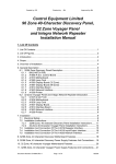
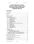
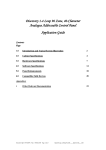
Nexus 1-8 Loop (A1557)
Analogue Addressable Control Panel
Installation and Commissioning Manual
Contents
Page
1.0
Introduction and Guided Tour
1
2.0
Cabinet Installation
7
3.0
Engineer’s Functions
9
4.0
Panel Check
10
5.0
Panel Configuration
10
6.0
Commissioning
20
Appendices
i.
Technical Specifications
24
ii.
Other Relevant Documentation
25
iii.
Compatible Loop Devices and Panel Responses
27
1.0
Introduction
Thank you for purchasing this Nexus 1-8 loop analogue addressable control panel. This range
of panels is designed to comply with to the requirements of BS5839 part 4 1988. The Nexus 18 loop panel will provide the user with many years of reliable service.
IMPORTANT NOTE: Read the instructions carefully before commencing installation and
commissioning.
1.1
Guided Tour
Document Ref: Nex8inst.doc/Rev0 09.07.00
Page 1 of 30
Originator MC Checked by AC___Approved by JBJ__
1.1.1
Exploded View and Mechanical Data/Text Identification
Motherboard
Expansion Motherboard
Display board assembly
mounted on removable door
Loop Cards
Loop Cards
Expansion Cards
Network Card A1535 8 way relay
A1536 8 way alarm
Power Supply Board
Space for Internal
12AH Battery Set
Printer
1.1.2
User Controls & Indications
Document Ref: Nex8inst.doc/Rev0 09.07.00
Page 2 of 30
Originator MC Checked by AC__
System disabled
illuminated when
detectors or inputs
are isolated
LCD display
4 x 20 character line
to display 2 events
Press to reveal
more messages on
the LCD display
Silence alarms
control. Press
Press to test the
to silence the
alarm sounders.
alarms.
Release to clear.
General fault
illuminates when
a general system
fault has occurred
Illuminates when the
the mains supply
is healthy.
LED flashes when
a fire is triggered. It
then goes steady when
the SILENCE ALARMS
is pressed.
Flashing LED in FIRE.
Prompts the user to
operate the SILENCE
ALARMS control in
accordance with the fire
proceedures in operation.
The LED then goes steady.
SUPPLY
HEALTHY
GENERAL
FAULT
FIRE
DISABLED
ACCEPT
SILENCE
ALARMS
RESET
SYSTEM
7
2
SCROLL
MESSAGES
CLEAR
DISPLAY
8
3
TEST
ALARMS
TEST
DISPLAY
9
4
ACCESS
MENU
SILENCE
BUZZER
0
5
OVERRIDE
DELAY
ESCAPE
#
6
EVACUATE
ENTER
*
DELAY
ON
SYSTEM
FAULT
ALERT
MORE
MESSAGES
Silence buzzer control.
Press to silence the fault
or alert buzzer.
Press to escape from
the engineer programme
function.
Press to enter
engineer's data
Press to access
engineers menu
via access code.
Press to override
the output delay.
Illuminates when
the panel is in
engineers test mode.
Evacuate control operates
the alarm circuits and the
fire relays. Press to operate
and press SILENCE ALARMS
to silence.
Illuminates when
there is a system fault.
Access Controls Keyswitch.
Position "0" inhibits all the controls.
Position "1" enables all the controls
Display Printed Circuit Boards as Viewed from Inside Cabinet
PROC RESET
EPROM WITH
SOFTWARE
REFERENCE
NODE ADDRESS
DIL SWITCH
DISPLAY
PROC FAILED
COMMS FAILED
PRINTER
INTERFACE
1.1.5
Test display to
test all LEDs and
panel buzzer.
ACCESS
CONTROLS
Flashes when there are
more events to be viewed
on the LCD display.
Pressing the SCROLL MESSAGES
will reveal the data until the
LED goes steady.
1.1.3
Press to clear the
LCD display after
a fault has been
cleared.
TEST
Illuminates when
the alarms and panel
outputs would be
delayed in the event
of a fire condition.
Illuminates when
a device is in
an alert condition.
1
System Reset
control. Press to
reset the system
after the Silence Alarms
has been pressed.
ZONE BOARD DISABLE
MONITORING LINK
B/+
A/SCN
B/+
A/SCN
FLT
24V
0V
CONNECT TO
MOTHERBOARD
FOR REPEATER
USE ONLY
24V AND 0V
SUPPLY
ZONE BOARD
INTERFACE
A1557 Motherboard Showing Essential Engineering Components
Document Ref: Nex8inst.doc/Rev0 09.07.00
Page 3 of 30
Originator MC Checked by AC__
Field terminals
J14
keyboard
port
Aux Flt
Aux Fire
n n p n n p p n
n
0 c 1 o c 2
o c
2 2
1 1
Aux I/O
Repeater
r r
m m r r
2
0
x x o 0 i i
4
v
++ - + v
Alarm Alarm Network
Loop1
n n n n l l l l
1
2
o o i i o o i i
+ - + - +
- + - + - + -
Remote inputs
s r e s c f
a s v b o l
l t c z v t
Loop 2
l l l l
o o i i
+- + -
A1549 zone
board interface
Fuse8
24V 1A
D0+
DO24v
0v
J5 - PC port
Fuse 7
24V 1A
Display
terminals
!
B1 - Lithium
clock battery
U2 EPROM
J4 A1558 expansion
board interface
J12 remove if
zone board
monitoring
required
Fuse 9 24V 3A
0
v
2
4
v
8
v
f
l
t
Processor, display
power and common
fault from PSU
AB CN
J3
[jumper
not fitted]
LBAR2
[See alarm list]
LBAR1
[See alarm list]
on
off
Fuse 10
24v 3A
0v
5v
Proc
failed
24v
2
4
v
Silence
Silence
Test
SW 1
alarms
buzr
alarms
Configuration
Local
Reset
Test
switches
evac
system
lamps
J9 Buzzer
enable
8
v
0
v
Loop power
from PSU
J6 - Network
card slot
LBAR 1 Alarm List.
LBAR2 Alarm List.
Comm failed.
Fire.
Alert.
Fault.
Isolated.
Supply fault.
Alarm fault.
Sil alarms.
Sil buzzer.
Sys reset.
Net enable.
LP1 enable.
LP2 enable.
LP3 enable.
LP4 enable.
LP5 enable.
LP6 enable.
LP7 enable.
LP8 enable.
J8- Loop 2
card slot
J7- Loop 1
card slot
!
Lithium Battery
Caution - danger of explosion if battery is incorrectly replaced. Replace only with same or
equivalent type recommended by the manufacturer. Dispose of used batteries according to
the manufacturers instructions. This battery should be replaced by trained service personnel
only.
Document Ref: Nex8inst.doc/Rev0 09.07.00
Page 4 of 30
Originator MC Checked by AC__
Power for
loop
expansion
board
A1557 Field Terminal List [Listed along the top edge of the PCB from left to right]
Terminal Ident.
Function
Terminal Ident.
Function
Aux Fire
NO 1
NC1
P1
NO 2
NC2
P2
P
NO
NC
24V
0V
MX+
MXRO +
RO RI +
RO SAL
Fire relay normally open 1
Fire relay normally closed 1
Fire relay pole 1
Fire relay normally open 2
Fire relay normally closed 2
Fire relay pole 2
Fault relay pole
Fault relay normally open
Fault relay normally closed
Aux DC supply [24V]
Aux DC supply [0V]
Local I/O expansion port +
Local I/O expansion port Repeater out +
Repeater out Repeater in +
Repeater in Silence alarms
Alarm 1
Sounder circuit 1 + [Active polarity]
Sounder circuit 1 - [Active polarity]
Sounder circuit 2 + [Active polarity]
Sounder circuit 2 - [Active polarity]
Panel network out +
Panel network out Panel network in +
Panel network in Loop 1 out +
Loop 1 out Loop 1 in +
Loop 1 in Loop 2 out +
Loop 2 out Loop 2 in +
Loop 2 in -
RST
EVC
SBZ
COV
FLT
Reset
Evacuate
Silence buzzer
Class change alarm
Fault
Aux Flt
Aux
I/O
Repeater
Remote
Inputs
1.1.6
Alarm 2
Network
Loop 1
Loop 2
+
+
NO +
NONI +
NI LO+
LOLI+
LILO+
LOLI+
LI-
Power Supply Illustration
+
+
12V
Document Ref: Nex8inst.doc/Rev0 09.07.00
Page 5 of 30
12V
Originator MC Checked by AC__
Loop Card Expansion Motherboard
l
o
-
l
i
+
Loop 3
Loop 4
l
i
-
l
o
+
l
o
-
l
i
+
l
i
-
l
o
+
Loop 5
l
o
-
l
i
+
Loop6
l
i
-
l
o
+
l
o
-
l
i
+
Loop 7
l
i
-
l
o
+
l
o
-
l
i
+
l
i
-
Loop 8
Loop 8 card slot
l
o
+
Loop 7 card slot
l
i
-
Loop 6 card slot
l
i
+
Loop 5 card slot
l
o
-
Loop 4 card slot
A1557 motherboard
connector
l
o
+
Loop 3 card slot
1.1.7
0V
5V
24V
1.1.8
Programmable Expansion Boards
Up to 31 A1535 (relay) and A1536 (alarm) programmable expansion boards may be connected
to the Nexus 1-8 loop (A1557) panel. Two boards may be housed internally, the remainder
require other enclosures. Refer to the A1535/A1536 Installation & Commissioning Manuals
for further details.
(i)
A1535 8 Way Programmable Input/Output Relay Board
The A1535 board provides 8 programmable inputs and 8 programmable relay circuit outputs.
(ii)
A1536 8 Way Programmable Input/Output Alarm Board
The A1536 board provides 8 programmable inputs (0V switched) and 8 programmable alarm
circuit outputs.
Document Ref: Nex8inst.doc/Rev0 09.07.00
Page 6 of 30
Originator MC Checked by AC__
2.0
Cabinet Installation
WARNING: Please read this section completely before commencing installation.
Prior to commencing installation of the control panel, ensure that adequate precautions are
taken against static damage to the sensitive electronic components on the control board. You
should discharge any static electricity you may have accumulated by touching a convenient
earthed object, e.g. an unpainted copper radiator pipe. You should repeat the process at
regular intervals during the installation process, especially if you are required to walk over
carpets.
The panel must be powered down before removing or replacing any card or module. Failure
to observe this may cause damage to the loop cards and the motherboard.
When changing any plug-in cards, observe anti-static precautions. Ensure that all power is
removed from the system. Failure to do so may result in damage to the cards or panel.
The panel must be located in a clean, dry position which is not subject to shock or vibration
and at least 2 metres away from pager systems or any other radio transmitting equipment.
The maximum temperature range is 0ºC - 40ºC; maximum humidity is 95%.
This equipment contains dangerous voltages. To prevent electric shock to unqualified
personnel ensure that the door is locked at all times when the panel is left unattended. Do
not leave the key to open the panel door with unqualified personnel. There are no userserviceable parts inside.
IMPORTANT NOTES ON BATTERIES:
DANGER: Batteries are electrically live at all times, take great care never to short circuit the
battery terminals.
DANGER: A lithium “coin cell” is fitted to the motherboard PCB. There is a danger of
explosion if this battery is incorrectly replaced. Replace only with same or equivalent type
recommended by the manufacturer. Dispose of used batteries according to the
manufacturer’s instructions. The replacement of this battery must be carried out by trained
service personnel only.
WARNING: Batteries are often heavy, take great care when lifting and transporting
batteries. For weights above 24 kilos, lifting aids should be used.
WARNING: Do not attempt to remove battery lid or tamper with the battery internal
workings. Electrolyte is a highly corrosive substance, and presents significant danger to
yourself and to anything else it touches. In case of accidental skin or eye contact, flush the
affected area with plenty of clean, fresh water and seek immediate medical attention.
VRLA batteries are “low maintenance” requiring no electrolyte top-up or measurement of
specific gravity.
WARNING: If required, clean the case with a cloth that has been soaked or dampened with
distilled water. Do not use organic solvents (such as petrol, paint thinner, benzene or mineral
spirits) and other materials can substantially weaken the case.
WARNING: Avoid operating temperatures outside the range of -15°C/5°F to +50°C/122°F
for float/standby applications.
Document Ref: Nex8inst.doc/Rev0 09.07.00
Page 7 of 30
Originator MC Checked by AC__
DANGER: Do not incinerate batteries. If placed in a fire, the batteries may rupture, with the
potential to release hazardous gases and electrolyte. VRLA batteries contain substances
harmful to the environment. Exhausted batteries must be recycled. Return them to the battery
manufacturer or take them to your Council tip for appropriate disposal.
We recommend that isolators are installed at both ends of each loop, immediately the loop
leaves the panel.
The volt-free relay contacts provided within the panel must not be used directly to switch any
voltage which exceeds 50VAC or 75VDC. (Please also refer to relay rating data).
This equipment requires a 230V AC supply. All installation work should be carried out in
accordance with the recommendations of BS5839 Part 1 and the current edition of the IEE
regulations by suitably qualified and trained personnel.
The panel must be earthed.
Locate the panel keys and the Installation Kit containing installation spares as follows:
2 off resistors 3K9
5 off 20mm glass fuses (assorted)
1 set of battery leads (positive, negative and a jumper lead)
Open the display door with the key provided. Carefully remove the control panel interior by
releasing the cables to the display (carefully noting the connections), the top two chassis
screws (located top left and right through the motherboard) and removing the lower two screws
(located bottom left and right) on the chassis plate. Open the right hand door and remove
chassis in similar manner.
Note: The chassis screws are bright chrome finnish
Fix the empty enclosure to the wall using the fixing hole(s) in the upper section of the
enclosure. Complete the fixing operation using the remaining fixing holes in the enclosure.
Gland installation wiring into the enclosure using the cable entry points provided. Leave plugs
in any unused cable entry holes.
Replace and fix the control panel chassis. Reconnect any internal earth wires.
Document Ref: Nex8inst.doc/Rev0 09.07.00
Page 8 of 30
Originator MC Checked by AC__
3.0
Engineer’s Functions
A number of engineering functions are provided by the control unit in order to allow the system
to be configured specifically to accommodate site requirements. Further functions are provided
to assist in commissioning and servicing the finished fire detection system.
There are three separate codes for access to the three engineer function levels. When the codes
have been entered, the user is guided through the sequence of operations, for the chosen
function, by text displayed on the LCD.
Prior to entering the engineers function menus, it is necessary to check that the panel is
configured to the correct quantity of loops, open the display door and locate the 4 position DIL
switch marked SW1. The switch settings are tabulated below:
SW1-3
OFF
OFF
OFF
OFF
ON
ON
ON
ON
SW1-2
OFF
OFF
ON
ON
OFF
OFF
ON
ON
SW1-1
OFF
ON
OFF
ON
OFF
ON
OFF
ON
NUMBER LOOPS
1 LOOP
2 LOOP
3 LOOP
4 LOOP
5 LOOP
6 LOOP
7 LOOP
8 LOOP
SW1-4 should be in the OFF position if the panel is to operate as a standard system. If the panel
is to operate as part of a network system then SW1-4 should be in the ON position.
Notes: The time/date function is now backed up by an internal lithium “coin cell”. This
battery is non rechargeable but at 70 mAh, will support the clock in conditions of total power
failure, for 10 years. The replacement of this battery is intended to be carried out by service
engineers only. The part number is CR1620.
The download lead is a standard “null-modem” RS232 lead with 9 pin D type connectors. This
can be supplied by CEL or obtained direct from Maplins - catalogue ref VD76H. New lead
connections below:
Panel end
Pin
Link
2
3
7
8
5
1
6
4
9
PC end
Pin
Link
3
2
8
7
5
4
1
6
9
The “Cherry” keyboard in current use can be connected directly to the motherboard via J14 5
pin Din socket without use of the converter lead.
Document Ref: Nex8inst.doc/Rev0 09.07.00
Page 9 of 30
Originator MC Checked by AC__
4.0
Panel Check
Ensure that the mains supply has been inspected and tested in accordance with BS5839 Part 1
and the current IEE regulations and that the system is correctly earthed.
4.1
Leave all test resistors in place and connect the 230V mains supply.
4.2
Switch on. The control panel should react as follows:
(i) The internal buzzer will sound
(ii) The “System on” LED will illuminate
(iii) The LCD will display a time [which needs to be checked)
5.0
Panel Configuration – Engineer’s Operating Instructions
NOTE: Please read the panel configuration options before proceeding to commissioning.
5.1
Introduction
The functions are intended to allow a complete system to be set up at site level. Three levels of
engineer functions are provided. The access system is arranged such that level 1 access only is
possible with code 1, levels 1 & 2 with code 2 and all levels with code 3. Level 1 functions are
intended for the end user. When the engineer functions are selected, the control panel in most
cases still fully operational i.e. an alarm condition will fully activate the panel. The only
options which cause the panel not to be fully operational are described later under “Status disabled” and “Sensor test”.
All engineering menu functions are available after operating the ACCESS CONTROLS key
switch and then pressing ENGINEER on the display, followed by input of the appropriate fourdigit access code.
If system is left in the engineers mode without controls being pressed, the panel will “time out”
to normal operation. Time-out periods vary, depending upon option selected, from 1 to 15
minutes.
5.2
Overview of Engineer’s Menu Options
5.2.1
Access level 1
1278
1:SET TIME/DATE
2:ISOLATE DEVICES
3:EDIT DEV/LOGO TEXT
Single device, range, de-isolate all, read.
Via PC or special QWERTY keyboard.
5.2.2
7218
Access level 2
4:CONFIGURE LOOP
Document Ref: Nex8inst.doc/Rev0 09.07.00
The panel will identify and report the type and quantity of sensors
Page 10 of 30
Originator MC Checked by AC__
used on the loop (i.e. ionisation smoke, optical smoke, or heat
sensor)
The analogue value can be identified & the detector self-tested, the
detector LED and the Remote LED can be turned on either in the
enabled mode or the disabled mode.
Panel reports loop content on the display.
255 zones (of which 64 are visible indication zones), programmable
across 8 loops and/or panel inputs.
Sounders operate for 1 second every 10 seconds.
Illuminates the device LED. Pulses the fire LED on the panel and
sounds the internal buzzer. No sounder operation, System
automatically resets after 25 seconds ready for the next device test.
Provides access to extended menu as detailed below:
5:DEVICE STATUS
6:LOOP CONTENTS
7:ZONE ALLOCATION
8:ALARM TEST
9:DEVICE TEST
0:EXTENDED MENU
1:ALERT TRIP LEVELS
2:FIRE TRIP LEVELS
3:PANEL DELAY
4:READ MEMORY
5:CLEAR PRINT QUEUE
6:NUMBER OF DISPLAYS
7:PRINT MEMORY
8:PRINT C/E DATA
5.2.3
Access level 3
8812
9:EDIT C/E DATA
0:NETWORK
5.3
Analogue values 35 - 50 in increments of 5.
Analogue values 55 - 70 in increments of 5.
Overridden by Delay Override, BGU or Evacuate.
Set enable period day/night, delay time 1-10 minutes
Enable/disable.
64 events - most recent first.
Clears events in printer queue.
Sets number of panel displays/repeaters.
64 events - most recent first.
Single output, loop address or full listing.
Panel and loop (See Cause/effect programming guide).
Configures panels in a network.
Accessing Engineer’s Menu
Note: You must operate the ACCESS CONTROLS keyswitch for all engineer’s and user
functions.
4
Step 1 - Press
0 9
P a n
- - - - - - - ENT ER CO
:
e
D
ACCESS MENU to reveal the following:
0 4 : 2 6
l
N a m e
- - - - - - - - - - E ,
P RE S S
*
Step 2 - Press appropriate Engineer’s code as section 4.2 above
eg
7
1
2
8
S E L ECT L EV
1 : S E T T I ME
2: : I S O L A T E
* NEXT P AG
Step 3 - Press
*
*
to reveal the following:
E L 2 O P T I ON
/ DAT E
DEV I CE S
E
# QU I T
to scroll through the Engineer’s Menu.
NOTE: No facility is accessible unless it is shown on-screen.
Document Ref: Nex8inst.doc/Rev0 09.07.00
Page 11 of 30
Originator MC Checked by AC__
Step 4 - Select the number of the engineer’s facility required by pressing the corresponding
number button.
5.4
Setting Time & Date
At Step 4 within the Engineer’s Menu (see Section 5.3 above), select 1:SET TIME/DATE.
S E L ECT L EVE L 2
ENT E R T I ME
h h
#
BACKS P ACE
O P T I ON
mm s s
*
ENT ER
Time is entered as two digits for each of the hours, minutes and seconds; eg 8am is 08:00:00.
The clock starts, at the time set, when the
*
ENTER key is pressed.
The date may then be entered as two digits for each of the day, month and year for example, the
3rd of August 1997 is 03:08:97. It is not necessary to press the ENTER key after entering the
date, the system automatically returns to normal operation.
5.5
Isolate
At Step 4 within the Engineer’s Menu (see Section 5.3 above), select 2:ISOLATE DEVICES.
Within this sub-menu, the following four options are available. Use the * to view these
options (if not currently displayed). Select the required option by pressing the corresponding
number button and then follow the on-screen instructions for each option.
I S
1 .
2 .
* N
O
S
P
X
LAT I O
ENS OR
ANE L
T P AG
N F AC I L I TY
S
I N P UT S
E
# QU I T
Enables the engineer to isolate/de-isolate loop devices
Enables engineer to isolate/de-isolate programmable panel inputs
To select next page (printer isolate)
Selecting Option 1. SENSORS reveals the following screen:
S ENSOR
I S O / DE
1 . S I NGL E
2 . R
3 . R EAD
4 . D
#
= QU I
- I SO
ANGE
E I S AL L
T
Enables the engineer to isolate/de-isolate a range of devices
Enables the engineer to de-isolate all the devices
Enables the engineer to view the devices isolated
Enables the engineer to isolate/de-isolate a single device
Within options 1 and 2 above of the Sensor Iso/Deiso screen, follow the on-screen instructions
to enter loop and sensor number(s). Press
following will appear:
I DENT I F Y
DEV I CE
Document Ref: Nex8inst.doc/Rev0 09.07.00
*
ENTER at each stage. A screen similar to the
Current Status
Page 12 of 30
Originator MC Checked by AC__
0 1 : 0 0 1
1 . I SO
DE - I S OLAT ED
2 . DE - I SO
#
= QU I T
Loop & device number
Press 2 to de-isolate
Press 1 to isolate
Selecting Option 2 . PANEL INPUTS on the ISOLATION FACILITY screen reveals the
following where the user is prompted to enter the input number followed by
I DENT I F Y
I N
I NPUT
0 0 1 D
1 . I SO
2 .
#
= Q
P
E
D
U
U
I
E
I
T
S OLAT ED
- I SO
T
*
ENTER.
Current Status
Press 2 to de-isolate
Press 1 to isolate
Input number
When any device is isolated, the DISABLED LED indicator on the panel will illuminate.
5.6
Edit
This option is used to enter device location messages and to enter the company name of the
installation. Text editing must be done using either the PC download facility or special
keyboard.
WARNING: We strongly recommend that no text editing should be attempted without the
use of the PC down-load facility due to the extensive range of options available. However, if
direct panel programming is unavoidable, a separate document entitled “Programming the
Nexus 1-8 Loop Analogue Addressable Control Panel Without a PC” is available.
5.7
Configure Loop
At Step 4 within the Engineer’s Menu (see Section 5.3 above), select 4:CONFIGURE LOOP.
Then follow on-screen instructions.
All devices on a loop must be configured using this option in order for the panel to respond to
these devices.
The control panel is automatically searching the detection loop circuit and noting the type of
devices at the various addresses. The process takes approximately 16 seconds to complete and
provides the following report:
P R I
SMO
HEA
OUT
5.8
OR I T
KE D
T DE
S TAT
I
E
T
I
E
T
E
O
S
EC TOR S
CTOR S
NS
0
0
0
0
0
0
0
0
0
0
0
0
Device Status
At Step 4 within the Engineer’s Menu (see Section 5.3 above), select 5:DEVICE STATUS.
Selection of this option provides interrogation and control of individual loop devices. Within
this sub-menu, the following three options are available:
Document Ref: Nex8inst.doc/Rev0 09.07.00
Page 13 of 30
Originator MC Checked by AC__
Selecting this option provides all the interrogation and control
functions. All output functions are disabled and only the
chosen device is being polled. This allows sensor devices to be
put into the test mode without alarms, etc. being raised and
allows observation of the rising analogue value.
1
2
3
DEV
D I S P
D I S P
P R I N
I C E
S TATUS
LAY
( D I S ABL ED )
LAY
( ENABL ED )
T DEV / S
S TATUS
Selection of this option causes the control panel to
output status information for all connected devices
to its printer (if fitted).
Selecting this option enables specified
devices to be interrogated and for commands to be sent to the devices. When the self test
mode is entered in this condition, the device under test should eventually enter an alarm
condition. When this occurs the control panel will react as if a genuine alarm condition
had been detected. The system will exit the engineer’s test mode and will need to be
silenced and reset in the normal manner.
5.8.1
Status Disabled/Enabled
Selecting Status options 1 or 2 will allow the engineer to enter the loop and device numbers.
The display then shows the following:
ADR VAL TYPE STS CMD
100 23 ION 000 000
ZONE 12 CMD BITS=123
4)PREV 5)NEXT #)END
The typical display example shown above is interpreted as follows:
The device address (ADR) is 100
The analogue value (VAL) is 23
The device type (TYPE) is ionisation smoke (ION)
The input status (STS) is 000
The control panel command status (CMD) is 000
The allocated zone for the device is 12
Key 4 allows the user to move to the previous device. The above example will be decreased to
address 99.
Key 5 allows the user to advance the address of the device being interrogated. The above
example will be advanced to address 101.
Key # to escape.
The device TYPES which may be indicated are as follows:
SOU Sounder circuit controller
- Device type code reference no. 1
O/S
Input/Output device
- Device type code reference no. 2
ION
Ionisation smoke sensor
- Device type code reference no. 3
MON Monitor (zone monitor, control monitor) - Device type code reference no. 4
OPT Optical smoke sensor
- Device type code reference no. 5
HEAT Heat sensor
- Device type code reference no. 6
BGU Call point or call point monitor
- Device type code reference no. 7
Document Ref: Nex8inst.doc/Rev0 09.07.00
Page 14 of 30
Originator MC Checked by AC__
The keypad keys 1, 2 & 3 become control switches for the 3 control panel command bits.
(Indicated by the numbers 123 under the CMD indicators).
Pressing key 1 causes command bit 1 to toggle between 0 and 1, key 2 for bit 2 and key 3 for
bit 3.
The 3 command bits have different purposes depending upon the device type. In the case of
smoke (ion and opt) and heat sensors, the command bit allocation is as follows:
1
2
3
Turn on Remote LED
Enter self test mode
Turn on Sensor LED
Break glass units respond to bits 2 & 3 only.
For command functions of other devices, refer to relevant literature.
Typical control example:
When a command bit is sent to a device, after a short delay, the status confirmation - returned
from the device - will be shown on the LCD. With the display as shown above, pressing key 3
turns on the sensor LED at device number 100. Pressing key 3 again turns it off.
WARNING: In the enabled condition the response of devices to the command codes will be
relatively slow due to the fact that the control panel is polling all connected devices and
command bits are required to be sent to the device twice.
When an ionisation sensor is tested, the display may briefly show an “ALERT” condition as
the sensor output rises. Other sensors react more quickly and appear to reach FIRE
condition immediately.
WARNING: If tests are carried out in the disabled mode, it is essential that the command
bits for each device be returned to 000 before moving on to another device. Failure to
observe this requirement will mean that, if a device has been left in the test mode, upon
returning to normal operation a fire alarm condition will be raised.
The control panel does clear the command bits upon return to normal operating condition
but the sensor devices respond too slowly and the control panel reads this as a fire alarm
condition.
To exit from the status option, press the # key. This returns the control panel to normal
operation.
5.8.2
Status To Printer
The format of the printed status report is shown in the short example below:
06/09/97 11:13:05
LOOP STATUS REPORT
ADR VAL TYPE ZONE
001 25 ION
1
Document Ref: Nex8inst.doc/Rev0 09.07.00
Page 15 of 30
Originator MC Checked by AC__
025 16
123 21
BGU
2
HEAT 4
END OF LOOP REPORT
5.9
Loop Contents
At Step 4 within the Engineer’s Menu (see Section 5.3 above), select 6:LOOP CONTENTS.
Selecting option 6 causes the display to show a list of the devices currently configured without
actually re-configuring the system. The format of the report is as shown under the
CONFIGURE Loop option previously explained (see section 4.7 above).
5.10
Zones
WARNING: We strongly recommend that no zone editing should be attempted without the
use of the pc down-load facility due to the extensive range of options available. However, if
direct panel programming is unavoidable, a separate document entitled “Programming the
Nexus 1-8 Loop Analogue Addressable Control Panel Without a PC” is available.
5.11
Alarm Test
The purpose of the Alarm Test facility is for audibility testing.
At Step 4 within the Engineer’s Menu (see Section 5.3 above), select 8:ALARM TEST and
follow on-screen instructions.
In this condition the control panel will automatically sound the panel and loop alarms and the
internal panel buzzer for 10 seconds every 15 seconds. This will continue until key 2 is pressed
or for a maximum of 15 minutes whichever occurs first.
All auxiliary outputs are disabled.
5.12
Device Test (Also known as the One Man Test Mode)
At Step 4 within the Engineer’s Menu (see Section 5.3 above), select 9:DEVICE TEST.
In this condition sensors may be triggered manually. Device operation illuminates the device
and LED pulses the fire LED on the panel and sounds the internal buzzer. No sounder
operation, System automatically resets after 25 seconds ready for the next device test. All other
outputs are disabled in this mode.
5.13
Extended Menu
At Step 4 within the Engineer’s Menu (see Section 5.3 above), select 0:EXTENDED MENU.
For options available within this extended menu, see section 5.2.1 above. Use
through options.
5.14
*
to scroll
Alert Trip Level
Document Ref: Nex8inst.doc/Rev0 09.07.00
Page 16 of 30
Originator MC Checked by AC__
This gives the option of adjusting the alert trip level of individual devices to suit particular
installation conditions. To adjust the trip level follow the procedure below:
At Step 4 within the Engineer’s Menu (see Section 5.3 above), select 0:EXTENDED MENU.
S E L
1 :
2 :
* N
E
A
F
E
C
L
I
X
T L EVE L 2 OP T I
E R T TR I P L EVE
RE T R I P
L EVE L
T P AGE
# QU I
ON
L S
S
T
Select 1: ALERT TRIP LEVELS & follow on-screen instructions, selecting loop & device no.
By repeatedly pressing the button designated TOGGLE, the engineer may view the various prealarm levels available.
The required level may be selected by pressing
5.15
*
OK, then
# to quit.
Fire Trip Level
This gives the option of adjusting the fire trip level of individual devices to suit particular
installation conditions. To adjust the trip level follow the procedure below:
At Step 4 within the Engineer’s Menu (see Section 5.3 above), select 0:EXTENDED MENU.
Select 2: FIRE TRIP LEVELS.
By repeatedly pressing the button designated TOGGLE, the engineer may view the various fire
trip levels available.
The required level may be selected by pressing
5.16
*
OK, then
# to quit.
Panel Delay
This gives the option to have a delayed response of panel and loop alarms & auxiliary relays to
a fire condition. This facility is programmed to be active during a specified period of the
day/night. The engineer must firstly set the time on/off period; this is the time of day/night
during which - if an alarm event were to occur - a delay would be effective. Secondly he must
select the period of the delay (1 - 10 minutes). Thirdly he must enable the delay for it to be
effective.
Document Ref: Nex8inst.doc/Rev0 09.07.00
Page 17 of 30
Originator MC Checked by AC__
At Step 4 within the Engineer’s Menu (see Section 5.3 above), select 0:EXTENDED MENU.
Select 3:PANEL DELAY. This will reveal the following:
Setting the time period of day or night during which, if a fire condition
occurred, the outputs would be delayed.
* * S
1 :
2 :
* N
E
T
D
X
T P ANE L DE LAY S * *
I ME ON / O F F
E LAY P ER I OD
T P AGE
# QU I T
Setting the output delay time. Press # to set 1 to 10 minutes.
Selecting 1: TIME ON/OFF will reveal the following two sub-menu options:
* * S E T P ANE L DE LAY S * *
1 :
T I ME ENAB L E
2 :
T I ME D I S AB L E
#
= QU I T
Selecting
following:
*
NXT
5.17
Setting the end of the time period
NXT PAGE in the SET PANEL DELAYS main menu, will reveal the
* * S E T P ANE L DE LAY S * *
3 :
EN / D I S DE LAY
*
Setting the beginning of the time period
P AGE
#
Enabling or disabling the panel delay function.
QU I T
Read Memory
At Step 4 within the Engineer’s Menu (see Section 5.3 above), select 0:EXTENDED MENU.
Selecting option 4 will cause the display to show the last 64 events held in the panel’s memory.
Press * to scroll through the events. Press # to exit to the main menu. The events are
displayed in reverse order i.e. most recent event first.
5.18
Clear Print Queue
At Step 4 within the Engineer’s Menu (see Section 5.3 above), select 0:EXTENDED MENU.
Select option 5 to clear all outstanding reports from the printer queue.
5.19
Programming the Number of Displays ( Repeaters )
Select Option 6: NUMBER OF DISPLAYS
This function is used to view/configure the number of displays connected to the control panel.
Display 01 is the panel’s own display. Displays 02 to 15 must be used for repeater panels.
NOTE: This function tells the main panel how many displays to look for. It must be used in
conjunction with the Nexus repeater panel manual where repeaters are used. Each display
Document Ref: Nex8inst.doc/Rev0 09.07.00
Page 18 of 30
Originator MC Checked by AC__
has its own DIL switch address setting. These addresses must be set in accordance with the
repeater panel manual. The panel’s own display DIL switch setting must not be changed.
* N UMB E R
D I S P LAY
OF D I S P LAYS *
0 1_
* = ENT E R ,
# = DE L E T E
Displays current status
To change number of displays
To accept number of displays
5.20
Print Memory Contents
At Step 4 within the Engineer’s Menu (see Section 5.3 above), select 0:EXTENDED MENU.
Select 7: PRINTER MEMORY.
The format of the printer memory report is shown in the short example below:
PANEL NAME
1:063 Z01 BGU FIRE
00:02:35
01/01/98
ALARMS SILENCED
00:02:42
01/01/98
SYSTEM RESET
00:02:45
01/01/98
5.21
Print Cause and Effect Data
At Step 4 within the Engineer’s Menu (see Section 5.3 above), select 0:EXTENDED MENU.
Selecting 8: PRINTER C/E DATA will print all local cause & effect information.
5.22
Options Available at Access Level 3
At Step 4 within the Engineer’s Menu (see Section 5.3 above), select 0:EXTENDED MENU.
Three options are available:
1) Edit Local Cause/Effect
2) Edit Network Cause/Effect
3) Print Network Cause/Effect
Select 9: EDIT C/E DATA.
Document Ref: Nex8inst.doc/Rev0 09.07.00
Page 19 of 30
Originator MC Checked by AC__
WARNING: We strongly recommend that no local cause/effect editing should be attempted
without the use of the pc down-load facility due to the extensive range of options available.
However, if direct panel programming is unavoidable, a separate document entitled
“Programming the Nexus 1-8 Loop Analogue Addressable Control Panel Without a PC” is
available.
Select 0: NETWORK
WARNING: We strongly recommend that no network cause/effect editing should be
attempted without the use of the pc down-load facility due to the extensive range of options
available. However, if direct panel programming is unavoidable, a separate document
entitled “Programming the Nexus 1-8 Loop Analogue Addressable Control Panel Without a
PC” is available.
6.0
Commissioning
6.1
Introduction
The following equipment should be available where possible to minimise commissioning time:
(i) VHF/UHF Portable Radio (for two engineers)
(ii) Multi-meter or equivalent
6.1.1
Checklist
Before commissioning, the engineer should check the following:
(i) All field wiring has been inspected and tested in accordance with CEL wiring
recommendations, BS5839 part 1 and current IEE wiring regulations.
(ii) All field cables are glanded into the control panel cabinet.
(iii) Detector bases are terminated but detector heads are not fitted. Any devices with
electronic components are not fitted. Terminations to devices with electronic
components should be linked through to maintain cable continuity.
(iv) Call points are not connected but cable is linked through to maintain continuity.
(v) No end-of-line devices (eg alarm circuit EOL resistor) are fitted.
6.1.2
The following information should be available to the commissioning team:
(i) Detection layout drawings and address information
(ii) Wiring schematic diagram
(iii) Panel Planning Sheet and Cause/Effect Sheet (where applicable)
(iv) PC or QWERTY keyboard for programming
(v) Control Panel installation manuals
(vi) Installation manuals for all equipment connected to the system
6.1.3
Experience has shown that tracing wiring faults on long circuits which are routed
through risers etc. can be difficult without knowledge of the wiring route.
Document Ref: Nex8inst.doc/Rev0 09.07.00
Page 20 of 30
Originator MC Checked by AC__
It is recommended that the electrical installer is made available until basic wiring continuity is
proven. A minimum of two persons (e.g. engineer and mate) is recommended for efficient
commissioning.
6.2
An Overview of the Commissioning Procedure
The approach to be used when commissioning a fire alarm system is to check each circuit and
function in turn to ensure correct operation of the entire system. In this way any faults may be
located quickly and accurately. The general procedures are as follows:
Alarm circuits should be checked first. The correct operation of each sounder should be
checked for correct audibility as specified in BS5839 part 1, using the “Test Alarms” facility.
Detection loops should be commissioned next. The purpose is to establish the correct
functioning of each device and checking for correct indication at the control panel. Any
auxiliary circuits may then be tested.
WARNING: Before testing, the engineer must be aware both of the operation of all devices
fitted to the auxiliary circuits and of the consequences of their operation.
6.3
Pre-Commissioning Wiring Check
NOTE: This pre-commissioning wiring check procedure should be followed to test all wiring
prior to specific commissioning of any detection, alarm and auxiliary circuits.
6.3.1
6.3.2
6.3.3
The following assumes that the control panel has been installed in accordance with the
installation procedure and is powered with only the “Power On” LED illuminated. Do
not connect field wiring at this stage.
Ensure that there are no devices connected to the loop and alarm circuits but the cables
are linked through at the device locations to achieve a continuous circuit.
Ensure that resistance of all cables to earth and between cores is more than 1MΩ.
Check the following:
(i) Positive to earth resistance is greater than 1MΩ
(ii) Negative to earth resistance is greater than 1MΩ
(iii) Positive to negative resistance is greater than 1MΩ
(iv) Place a short circuit across the ends of the loop and alarm circuits. Measure the
resistance across the positive and negative cables of each of the circuits and ensure
that the value does not exceed the value calculated on the Loop Calculator
Spreadsheet. Remember to remove the short circuits after the tests.
Correct polarity throughout all circuits must be maintained. Rectify any faults.
6.3.4
Power down panel. All bells, detector heads and call points should now be connected
and alarm circuit end-of-line resistors fitted. Use the spare end-of-line resistors
supplied and leave the EOL resistors in the panel terminals at this stage. Be very
careful to maintain correct polarity at each device.
6.4
Commissioning Procedure
6.4.1
Alarm Circuits
After completion of the pre-commissioning wiring check, this procedure should be followed:
Document Ref: Nex8inst.doc/Rev0 09.07.00
Page 21 of 30
Originator MC Checked by AC__
(i)
Remove the resistor from the first alarm circuit terminal and connect the first alarm
circuit wiring to the terminals, observing correct polarity. Check that any alarm fault
indications clear after a few seconds.
(ii)
Press the “Evacuate” switch. Check that all sounders connected to the alarm circuit
operate.
(iii)
Press “Silence Alarms” and “Reset”.
(iv)
Repeat steps (5.4.1) to (5.4.3) for the second and any subsequent alarm circuits.
6.4.2
Commissioning Loops
NOTE: The pc down-load facility may be used at any stage up to Section (v).
(i)
Insulate and physically protect the positive and negative ends of one end of the
detection loop wiring. Connect the other end of the wiring to the panel terminals LO+
and LO- for loop 1.
(ii)
Enter the engineers test mode at level 2 and select option 4 (Configure). After the
configuration period, the panel will report the numbers of the different types of sensors.
If the numbers and types of sensor agree with the physical check already carried out,
proceed to the next stage (iv).
(iii)
If double addressing of detectors is found on the loop, the LCD display will show a
report of the device numbers affected. The engineer may also notice a device missing
from the expected total quantity of loop devices.
(iv)
When all required sensors have been configured, select engineer’s Option 5: STATUS
and using the STATUS DISABLED option, interrogate the devices on an individual
basis. To view correct electronic operation, press button for command bit 2 (self test
mode). Press again to return detector to quiescent state. To turn a device LED on (to
identify its correct location), press button for command bit 3. Press again to return
detector to quiescent state. To turn a remote device LED on (to identify its correct
location), press button for command bit 1. Press again to return detector to quiescent
state.
(v)
Repeat sections (i) to (iv) for each loop.
(vi)
Sensor installation is now complete and the return end of the detection loop may now
be connected to the LI+ and LI- terminals.
WARNING: Before connecting, ensure that the returning polarity is correct.
The final phase of the sensor commissioning involves replacing all the short circuit isolators.
The supply polarity to isolators is important and must be checked and corrected if necessary
before fitting the isolator.
WARNING: If the isolator polarity is found to be incorrect, it is absolutely essential that the
polarity is corrected at each termination point throughout the wiring. Failure to observe this
will result in the polarity of the return end of the cable becoming incorrect with the
possibility of damage to the control panel.
6.5
A1535 (Programmable Relay Expansion Boards) and A1536
(Programmable Alarm Expansion Boards)
Document Ref: Nex8inst.doc/Rev0 09.07.00
Page 22 of 30
Originator MC Checked by AC__
Refer to the Installation & Commissioning Manuals for these boards.
6.6
Auxiliary Circuits
Any auxiliary circuits or equipment which is not supplied as a standard part of the fire alarm
panel is the responsibility of the installer and must be tested for safe and correct operation by
the commissioning engineer. If special output facilities are provided as extra equipment, refer to
separate drawings and manuals for commissioning information.
6.7
Cause & Effect Editing
The Nexus panel may now be programmed with the text, zone and cause & effect information.
WARNING: We strongly recommend that no cause & effect programming should be
attempted without the use of the pc down-load facility due to the extensive range of options
available. However, if direct panel programming is unavoidable, a separate document
entitled “Programming the Nexus 1-8 Loop Analogue Addressable Control Panel Without a
PC” is available.
6.7.1
Cause & Effect Testing
Testing of the panel’s fire and fault relays and all cause & effect outputs must be done with the
system fully functional. There are two options:
(i) Operate field devices and physically check programmed output devices for correct
operation.
(ii) Select engineer’s option 5: STATUS and operate devices with the System Enabled
option as described in the Nexus 1-8 Loop Installation Manual. This will cause
selected devices to go into fire and operate the panel’s cause & effect programming.
Physically check programmed output devices for correct operation.
6.8
Final Commissioning
6.8.1
Select engineer’s Option 9: DEVICE TEST and carry out tests on all sensor devices.
6.8.2
Testing of the panel’s fire and fault relays and all cause & effect outputs must be done
with the system fully functional.
There are two options for testing the panels cause & effect:
(i) Operate devices as required
(ii) Use engineer’s Option 5: STATUS, selection 1 SYSTEM ENABLED to operate
devices
Document Ref: Nex8inst.doc/Rev0 09.07.00
Page 23 of 30
Originator MC Checked by AC__
Appendices
i
Technical Specifications
NOTE: Due to the wide scope of panel options, we strongly recommend the use of our
battery calculation chart which is available on PC disk or as hard copy. The information
below should not be used to calculate standby battery size.
Power Supplies
Mains input voltage:
System operating voltage:
Quiescent current at 24V DC:
Quiescent loop card current
Loop card max. current
Power supply max:
Alarm power output max:
Auxiliary output max:
Battery charger output:
Battery type:
230V AC -6% + 10%
24V DC
375mA (A1557. A1508, A1575 – no loop cards)
65mA + 1.3 x loop current
200mA
5 Amps @ 24V DC
1 Amp per circuit @ 24V DC (Note 3)
0.5 Amp @ 24V DC (Note 4)
1.5 Amps (Note 5)
24V sealed lead acid
Output Circuits
Alarm circuits:
Alarm circuit monitoring:
Repeater output:
Printer output:
Multiplex inputs/outputs:
Panel Network:
Alarm fuse rating:
Battery fuse rating:
Auxiliary fuse rating:
Mains fuse rating:
2
Open/short circuit (Note 6)
Serial data RS485 (Note 7)
Parallel
248 (via A1535/A1536 boards)
Connection of 15 panels via Network data link
1 Amp thermal resetable fuse
6.3 Amp (20mm glass)
0.5 Amp (20mm glass)
3 Amp (20mm glass)
Input Circuits
Detection loops:
Detection loop fuse rating:
No. of sensors on loop:
Cable 1.5mm (max. length - 2km)
250mA thermal resetable
126 maximum (Note 9)
Relay Outputs
2 independent relays are provided which operate as follows:
Fire relay:
1 double pole changeover, operates on any fire alarm
Fault relay:
1 single pole changeover operates on any fault signal
All relay contacts are rated at 24V DC 1 Amp.
Cable Terminations
Mains terminals:
Alarm and loop terminals:
All other terminals:
Shrouded, marked & fused, accept max 2.5mm2 cables
Screw terminals, accept max. 2.5mm2 cables
Screw terminals, accept max. 2.5mm2 cables
All terminal functions are identified by screen printing on the circuit boards.
Document Ref: Nex8inst.doc/Rev0 09.07.00
Page 24 of 30
Originator MC Checked by AC__
NOTES:
1.
We strongly recommend the use of the Battery and Loop calculator for assessing the
correct size of the standby batteries and correct loop function in all conditions.
2.
Quiescent current is stated assuming mains failure conditions, therefore the general
fault LED will be illuminated and the fault buzzer will sound.
3.
The total current drawn by both alarm circuits operating must not exceed 2 Amps.
4.
The total DC auxiliary current drawn must not the values stated in the Technical
Specification. The power supply current limiting will operate if ratings are exceeded.
5.
The battery charger employed is the constant voltage type and the current will be
dependent upon the state of charge of the battery.
6.
Alarm line monitoring operates using polarity reversal. All alarm sounders and/or
visual alarms must be made polarity sensitive for line monitoring to operate correctly.
7.
Repeater data output is available at terminals in the control panel. Two cores are
required for the connection of repeater panels. The maximum cable length between the
control unit and any repeater unit is 2000 metres. The cable must be suitable for RS485
data such as Belden 8132 or equivalent. If power is provided from the control unit, 2
additional cores are required.
8.
The control panel provides an RS485 multiplex data link for driving additional output
devices such as zonal relays, alarms, mimic indicators etc. The output functions are
programmable at site level.
9.
The number of sensor devices may need to be reduced due to the power requirements
of the devices themselves. Fire sensors, heat smoke, call points etc. may be fitted in any
combination up to the maximum (126) addressing capability of the protocol. Zone
monitors in particular require a higher operating voltage and also draw significantly
more current from the control unit; reference to the system design manual is necessary
if zone monitors are to be used on the loop.
10.
If any devices which contain an inductive coil (relays etc.) are connected to the panel,
these should be suppressed by connecting a diode across the positive and negative
connections of the coil.
ii
Other Relevant Documentation
Sales Literature
Nexus 1-8 Loop Application Guide
Nexus 1-8 Loop User Instructions
Nexus Repeater Documentation
A1535 8 Way Relay Board Documentation
A1536 8 Way Alarm Board Documentation
PC-Based Software Programming Guide
Wiring Recommendations
Battery and loop Calculation Software
Document Ref: Nex8inst.doc/Rev0 09.07.00
Page 25 of 30
Originator MC Checked by AC__
iii
Compatible Loop Devices and Panel Responses
The following table shows all devices compatible with the panel. It shows the panel’s response to events from each device type, and indicates the change in
analogue value and input bits that will be displayed in the status mode. Note that some device types automatically receive cause effect outputs by default. Any such
programming is indicated in the default cause and effect column.
Device type
CEL sounder
controller
Type
Code
1
CEL Loop
powered sounder
1
Series 90
sounder/ sounder
controller
XP95 sounder/
sounder
controller
CEL I/O unit
1
Series 90 3-way
I/O unit
1
2
2
Condition
Panel response
Analogue Value
Quiescent
Input 1 operated
Input 2 operated
Input 3 operated
Circuit fault
Quiescent
Fault
None
Mode 1
Mode 2
Remote fault
Remote fault
None
Remote fault
AV = 16
AV = 64
AV = 48
AV = 4
AV = 4
AV = 16
AV = 4
Status bits
(210)
000
000
000
000
000
Echo
output bits
Quiescent
Circuit fault or fault
input operated
Quiescent
Circuit fault
None
Remote fault
AV = 16
AV = 4
Echo
output bits
None
Remote fault
AV = 16
AV = 4
Echo
output bits
Quiescent
Input 1 operated
Input 2 operated
Input 3 operated or
power supply failed
Quiescent
Input 1 operated
Input 2 operated
Input 3 operated
None
Fire
Input
Remote fault
AV = 16
AV = 64
AV = 48
AV = 4
000
000
000
000
None
Fire
Input
Remote fault
AV = 16
AV = 16
AV = 16
AV = 16
000
1XX
01X
001
Document Ref: Nex8inst.doc/Rev0 09.07.00
Page 26 of 30
Originator MC Checked by AC___Approved by JBJ__
Output bits
0 = evacuate
1 = alert
2 = relay
0 = evacuate
1 = alert
2 = not used
0 = evacuate
1 = alert
2 = not used
0 = evacuate
1 = alert
2 = not used
0 = relay 1
1 = relay 2
2 = relay 3
0 = relay 1
1 = relay 2
2 = relay 3
Default cause
and effect
Bit 0 set on
evacuate
Comments
Bit 0 set on
evacuate
Bit 0 set on
evacuate
Bit 0 set on
evacuate
X means status
does not affect
panel status
Device type
Series 90 3-way
I/O analogue unit
Type
Code
2
Condition
Panel response
Analogue Value
Quiescent
Input 1 operated
Input 2 operated
Input 3 operated
Quiescent
Input operated
None
Fire
Input
Remote fault
None
Fire
AV = 8 to 44
AV = 55 to 127
AV = 45 to 54
AV = 0 to 7
AV = 16
AV = 16
Status bits
(210)
000
1XX
01X
001
000
001
Series 90 1-way
I/O unit
2
Series 90 switch
monitor unit
2
Quiescent
Input operated
None
Fire
AV = 16
AV = 16
000
100
XP95 I/O unit
2
XP95 output unit
Series 90
ionisation smoke
2
3
3
CEL zone
monitor
4
None
Fire
Input
Remote fault
None
None
Fire
Alert
Data fault
None
Fire
Alert
Data fault
None
Fire
Alert
Remote fault
AV = 16
AV = 16
AV = 16
AV = 4
AV = 16
AV = 8 to 44
AV = 55 to 127
AV = 45 to 54
AV = 0 to 7
AV = 8 to 44
AV = 55 to 127
AV = 45 to 54
AV = 0 to 7
AV = 16
AV = 64
AV = 48
AV = 4
000
1X0
010
000
000
Echo
output bits
XP95 ionisation
smoke
Quiescent
Input operated
Opto input active
Input fault
Quiescent
Quiescent
Fire
Alert
Fault
Quiescent
Fire
Alert
Fault
Quiescent
Input 1 operated
Input 2 operated
Input 3 operated
Document Ref: Nex8inst.doc/Rev0 09.07.00
Page 27 of 30
Output bits
Default cause
and effect
Comments
X means status
does not affect
panel status.
See note 2.
0 = relay 1
1 = relay 2
2 = relay 3
0 = relay
1 = not used
2 = not used
0 = remote
indicator
1 = not used
2 = not used
0 = remote
indicator
1 = not used
2 = not used
0 = relay
0 = remote LED
1 = self test
2 = LED
Bit 0 and bit 2
set when device
is in fire
See note 1.
Echo
output bits
0 = remote LED
1 = self test
2 = LED
Bit 0 and bit 2
set when device
is in fire
See note 1.
000
000
000
000
0 = relay 1
1 = relay 2
2 = relay 3
Bit 0 set on
reset or clear
faults
Originator MC Checked by AC__
Fire overrides
input which in
turn overrides
remote fault
Device type
Series 90 zone
monitor
Type
Code
4
Series 90 control
unit monitor
4
XP95 Miniswitch monitor
4
XP95 Switch
monitor
4
XP95 Switch
monitor plus
4
XP95 Zone
Monitor
4
XP95 control unit
monitor
4
XP95 Radio
Interface
4
Condition
Panel response
Analogue Value
Quiescent
Fire
Circuit fault
Quiescent
Alarm
Circuit fault
Quiescent
Alarm
Alert
Circuit fault
Quiescent
Alarm
Alert
Circuit fault
Quiescent
Alarm
Alert
Circuit fault
Quiescent
Alarm
Circuit fault
Quiescent
Alarm
Circuit fault
Quiescent
Alarm
Circuit fault
None
Fire
Remote fault
None
Fire
Remote fault
None
Fire
Alert
Remote fault
None
Fire
Alert
Remote fault
None
Fire
Alert
Remote fault
None
Fire
Remote fault
None
Fire
Remote fault
None
Fire
Remote fault
AV = 16
AV = 64
AV = 4
AV = 16
AV = 64
AV = 4
AV = 16
AV = 64
AV = 45 - 51
AV = 4
AV = 16
AV = 64
AV = 45 - 51
AV = 4
AV = 16
AV = 64
AV = 45 - 51
AV = 4
AV = 16
AV = 64
AV = 4
AV = 16
AV = 64
AV = 4
AV = 16
AV = 64
AV = 4
Document Ref: Nex8inst.doc/Rev0 09.07.00
Page 28 of 30
Status bits
(210)
Echo
output bits
0 = reset
1 = test
2 = LED
0 = fault test
1 = alarm test
2 = remote LED
0 = fault test
1 = alarm test
2 = LED
Default cause
and effect
Bit 0 set on
reset or clear
faults
Bit 0 set on
reset or clear
faults
Bit 0 set on
reset or clear
faults
Program LED
bit in cause
effect if required
Program LED
bit in cause
effect if required
Program LED
bit in cause
effect if required
Echo
output bits
0 = not used
1 = alarm test
2 = LED
Bit 0 set on
reset or clear
faults
Program LED
bit in cause
effect if required
Echo
output bits
0 = opto-reset
1 = alarm test
2 = LED
Bit 0 set on
reset or clear
faults
Program LED
bit in cause
effect if required
Echo
output bits
0 = reset
1 = alarm test
2 = LED
0 = reset
1 = alarm test
2 = LED
0 = reset
1 = alarm test
2 = LED
Bit 0 set on
reset or clear
faults
Bit 0 set on
reset or clear
faults
Bit 0 set on
reset or clear
faults
Program LED
bit in cause
effect if required
Program LED
bit in cause
effect if required
Echo
output bits
Echo
output bits
Echo
output bits
Echo
output bits
Originator MC Checked by AC__
Output bits
Comments
Device type
Series 90 optical
smoke
Type
Code
5
XP95 optical
smoke
5
XP95 beam
Detector
5
XP95 flame
detector
5
XP95 multisensor opt/heat
detector
5
Series 90 heat
detector
6
XP95 heat
detector standard
6
Condition
Panel response
Analogue Value
Quiescent
Fire
Alert
Fault
Quiescent
Fire
Alert
Fault
Quiescent
Fire
Alert
Fault
Quiescent
Fire
Alert
Fault
Quiescent
Fire
Alert
Fault
Quiescent
Fire
Alert
Fault
Quiescent
Fire
Alert
Fault
None
Fire
Alert
Data fault
None
Fire
Alert
Data fault
None
Fire
Alert
Data fault
None
Fire
Alert
Data fault
None
Fire
Alert
Data fault
None
Fire
Alert
Data fault
None
Fire
Alert
Data fault
AV = 8 to 44
AV = 55 to 127
AV = 45 to 54
AV = 0 to 7
AV = 8 to 44
AV = 55 to 127
AV = 45 to 54
AV = 0 to 7
AV = 8 to 44
AV = 55 to 127
AV = 45 to 54
AV = 0 to 7
AV = 8 to 44
AV = 55 to 127
AV = 45 to 54
AV = 0 to 7
AV = 8 to 44
AV = 55 to 127
AV = 45 to 54
AV = 0 to 7
AV = 8 to 44
AV = 55 to 127
AV = 45 to 54
AV = 0 to 7
AV = 8 to 44
AV = 55 to 127
AV = 45 to 54
AV = 0 to 7
Document Ref: Nex8inst.doc/Rev0 09.07.00
Page 29 of 30
Status bits
(210)
Echo
output bits
0 = remote LED
1 = self test
2 = LED
Default cause
and effect
Bit 0 and bit 2
set when device
is in fire
Echo
output bits
0 = remote LED
1 = self test
2 = LED
Bit 0 and bit 2
set when device
is in fire
See note 1.
Echo
output bits
0 = remote LED
1 = self test
2 = LED
Bit 0 and bit 2
set when device
is in fire
See note 1.
Echo
output bits
0 = remote LED
1 = self test
2 = LED
Bit 0 and bit 2
set when device
is in fire
See note 1.
Echo
output bits
0 = remote LED
1 = self test
2 = LED
Bit 0 and bit 2
set when device
is in fire
See note 1.
Echo
output bits
0 = remote LED
1 = self test
2 = LED
Bit 0 and bit 2
set when device
is in fire
See note 1.
Echo
output bits
0 = remote LED
1 = self test
2 = LED
Bit 0 and bit 2
set when device
is in fire
See note 1.
Originator MC Checked by AC__
Output bits
Comments
See note 1.
Device type
XP95 heat
detector high
Type
Code
6
Series 90
callpoint/
callpoint monitor
7
XP95 callpoint
7
XP95 Mini
switch monitor
with interrupt
XP95 USA mini
priority switch
monitor
7
7
Condition
Panel response
Analogue Value
Quiescent
Fire
Alert
Fault
Quiescent
Alarm
Fault
None
Fire
Alert
Data fault
None
Fire
Fault
AV = 8 to 44
AV = 55 to 127
AV = 45 to 54
AV = 0 to 7
AV = 16
AV = 64
AV = 4
Quiescent
Alarm
Fault
Quiescent
Alarm
Fault
Quiescent
Alarm
Fault
None
Fire
Fault
None
Fire
Fault
None
Fire
Fault
AV = 16
AV = 64
AV = 4
AV = 16
AV = 64
AV = 4
AV = 16
AV = 64
AV = 4
Status bits
(210)
Echo
output bits
Output bits
0 = remote LED
1 = self test
2 = LED
Default cause
and effect
Bit 0 and bit 2
set when device
is in fire
L10
L01
L10
0 = remote LED
1 = self test
2 = LED
Bit 2 set when
in fire
L10
L01
L10
L10
L01
L10
L10
L01
L10
0 = remote LED
1 = self test
2 = LED
0 = remote LED
1 = self test
2 = LED
0 = remote LED
1 = self test
2 = LED
Bit 2 set when
in fire
Bit 2 set when
in fire
Bit 2 set when
in fire
Comments
See note 1.
Input bit 2
confirms LED
operation and is
represented by L
Input bit 2
confirms LED
operation
Input bit 2
confirms LED
operation
Input bit 2
confirms LED
operation
Notes:
The analogue thresholds for analogue detectors can be changed for both fire and alert. See the installation and commissioning manual for details.
On the S90 3-way analogue unit, either the analogue value or logic inputs can raise alarms. The analogue thresholds can also be changed for fire and
alert on this device. See the installation and commissioning manual for details.
The number of devices with LEDs operated is limited to eight per loop.
If a device has more than one condition active then only the highest level event will be reported although lower level alarms may be present on the
display. For example, if a smoke detector enters an alert condition this will be indicated on the panel. If the device subsequently enters a fire
condition the alert will clear but the alert LED will become steady to indicate the event occurred.
Document Ref: Nex8inst.doc/Rev0 09.07.00
Page 30 of 30
Originator MC Checked by AC__