1
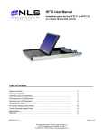
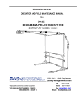
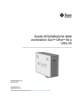
17 inch LCD/Keyboard Rack Kit
Installation guide for the RFT-17 Line
into a 4-post 19-inch EIA cabinet
Table of Contents
Hardware Installation… ……………………………………………………………………
Connecting your LCD/Keyboard…………………………………………………………
Operating your LCD/Keyboard..………………………………………………………….
Navigating the Menu.……………………………………………………………………….
On-Screen Display (OSD) Menus…………………………………………………………
Trouble Shooting Bad Image Quality……………………………………………………
Specifications……………………………………………………………………………….
Warranty………………………………………………………………………………………
Neuro Logic Systems, Inc.
02/01/05
2
5
6
8
9
10
12
13
Page 1 of 14
17 inch LCD/Keyboard Rack Kit Installation Guide
Page 2 of 14
17 inch LCD/Keyboard Rack Kit Installation Guide
Hardware Installation
Step
Detail
1. Determine the vertical location for the LCD/keyboard
in the rack. Mark the location with tape or a pencil.
This product requires one rack unit (1 ¾”) of vertical
space. Mount the LCD/keyboard at a convenient
height for an average user. (Approx 44” from floor)
Ensure the bottom of the kit is properly positioned in a
rack unit
2. Measure the distance from the front rack mounting
rail to the rear rack mounting rail. (This distance will
be needed during installation of the Rear slide
mounting brackets in step 4)
Distance= _____________
Page 3 of 14
17 inch LCD/Keyboard Rack Kit Installation Guide
Step
3. Remove the slides from the tray assembly. The
slides come shipped attached to the tray assembly,
the outer slide members must be removed to be
properly installed into the rack. To remove the outer
slide members, fully extend both slides to the open
position. Once extended unlock the outer slide
members by lifting up on the left side latch and
pressing down on the right slide latch. The outer
slide member can now be removed from the tray
assembly. The inner slides are left attached to the
tray assembly.
Detail
Lift Up
Push Down
4. Adjust the rear slide mounting brackets to the proper
depth. The rear slide mounting brackets are preassembled, but may need to be adjusted to the
proper distance measured in step 2. There is
multiple screw holes in the rear slide mounting
brackets and slide rails. You can use any of these
holes. Do not tighten screws until after you install the
slides in the rack, as you may need to make small
adjustments.
5. Insert nut clips into the rack mounting rails as
required. If your rack has square or round untapped
holes, you will need to use 10-32 nut clips.
Page 4 of 14
17 inch LCD/Keyboard Rack Kit Installation Guide
Step
Detail
6. Attach the left slide rail assembly to the rack
mounting rail by using (6) #10-32 x ½” screws for the
front and rear slide mounting brackets. Repeat for
the right slide rail assembly.
7. Tighten the screws that attach the rear slide mount
bracket to the outer slide member. (From step 4)
(4X)
8. Extend the slides from the rack.
9. Install the LCD/keyboard assembly into the rack. Lift
the tray assembly and approach the rack with the
rear of the tray facing the rack enclosure. Align the
tray assembly with the slide rails in the rack.
Carefully assemble the two slide members together.
Push the tray assembly in until the slides latch
together. Release the lock mechanisms as shown in
step 3 in order to slide the tray assembly completely
closed.
Page 5 of 14
17 inch LCD/Keyboard Rack Kit Installation Guide
Connecting your LCD/Keyboard
Step
Detail
! Note: Before connecting the LCD monitor/keyboard to a
KVM or Sun System, all systems should be turned off.
1. The keyboard and trackball’s design allows its use with
most Sun systems. The LCD-17-8P com es with an 8pin Din keyboard connector, while the LCD-17-USB
comes with a USB style connector.
2. The monitor uses a standard HD-15 male video
connector. If your Sun system uses a DB13W3
connection, you can use a Sun adapter to interface
between the LCD connector and the Sun system. (PN:
X3872A)
3. Connect the monitor to a power source. The LCD
Monitor’s power supply is auto ranging, and will operate
on AC voltages ranging from 90-264 and 50-60 Hz. The
monitor uses an IEC 320-C14 connector. An adapter will
be required to interface with other connector types.
4. Secure the cables to ensure they will not bind when
operating the LCD/keyboard slide mechanism. Cycle the
tray in and out of the cabinet to ensure there is enough
of a service loop in the cables.
Page 6 of 14
17 inch LCD/Keyboard Rack Kit Installation Guide
Operating your LCD/Keyboard
NOTE: It is important to ensure that the monitor is connected and powered on prior to powering up the connected
Sun system. By powering up the Sun System last it will allow the frame buffer within the Sun system to
communicate with the LCD monitor and self configure to the correct settings.
After the unit has been installed and all cables connected, power on the LCD monitor by lifting the head unit.
(There is a power button at the rear of the LCD which is actuated by lifting the head of the LCD monitor.) The LED
situated on the top of the LCD panel will alert you to its status. It will illuminate green when everything is working
properly. If the LED is orange, the monitor is powered up but not receiving a valid video signal.
(On some models the menu panel may be located on the back of the LCD)
NOTE: If the monitor does not power up automatically when raised, the power button at the rear of the monitor
may need to be cycled. There is also a Power button on the top of the LCD which may also need to be cycled.
Once the LCD monitor is powered on, power on the connected Sun system and log in (or otherwise ensure that a
full screen image is displayed). Now press the monitor AUTO/SEL button. This will Auto-adjust the display to
optimum performance.
NOTE: It is important to ensure that a full screen image is being displayed at the time the monitor is in the AutoAdjust function. The display may be miss-positioned if an image with a black border (such as a CDE login Screen)
or partial screen is used.
NOTE: The display resolution should self configure to 1280x1024 resolution at 60Hz. With some older Creator
and Creator3D frame buffers, the monitor will self configure to 1152x900 resolution at 66Hz. This is normal since
these old frame buffers do no support 1280x1024x60Hz resolution. To check the current resolution of the monitor,
Page 7 of 14
17 inch LCD/Keyboard Rack Kit Installation Guide
press the Menu button at the rear of the LCD panel twice, which will select the Display Mode menu. Note that
deviations of a fraction of a hertz in the displayed refresh rate are not significant.
NOTE: If the monitor self configures to any other resolution, it is likely that the frame buffer has been explicitly
configured to display that particular resolution. If running Solaris 8 or above, use the “fbconfig –defaults”
command to reset the resolution to the default, and then reboot the system. With earlier versions of Solaris, use
the appropriate command for your particular frame buffer (E.g. “ffbconfig – defaults” for the Creator[3D] frame
buffer).
Page 8 of 14
17 inch LCD/Keyboard Rack Kit Installation Guide
Navigating the Menu
(on some models the menu panel may be located on the back of the LCD)
The LCD monitor will auto-adjust at start-up. Although not required, you can make numerous adjustments to your
monitor using the on-screen menu. To access the OSD (On-Screen Display) menu Press the MENU button
located at the top of the LCD monitor.
The table below describes various function controls of the LCD Monitor. The control buttons can be accessed
from the top of the LCD monitor once it has been raised in to the operating position. The OSD menu will
disappear after a pre-set time of no use.
Function when not
displaying menu
Function when displaying
menu
Menu button
Displays the On-Screen
Display (OSD)
Selects the next page of the
menu
<
Brightness/minus
Decrease display brightness
Decreases or changes value
of the adjustment item
>
Brightness/plus
Increase display brightness
Increases or changes value of
the adjustment item
AUTO/SEL
Auto/Select
Activates the Auto Adjust
function to obtain an optimum
image
Selects a menu item
Power switch
Turn power on and off
manually
Turn power on and off
manually
Label
Control
MENU
Page 9 of 14
17 inch LCD/Keyboard Rack Kit Installation Guide
On-Screen Display (OSD) Menus
The menu pages can be displayed by pressing the Menu button. Not all menu functions can be adjusted. (Menu
items or layout may change without notice)
Menu Page 1
Auto-Adjustment
Contrast
Horizontal Position *
Vertical Position *
Frequency *
Tracking *
This function is used to obtain an optimum image
Adjusts the contrast of the display
Changes the horizontal position of the image
Changes the vertical position of the image
Changes the display data frequency
Synchronizes the signal timing
Menu Page 2
Display Mode
Displays the current resolution and frequency
OSD Off Time
Adjusts the time that the OSD takes to disappear
Language
Selects the OSD language
Text-Graphic Mode
Not available for change
Sharpness
Not available for change
Reset
Resets the monitor to factory default settings
Menu Page 3
Volume
Sound not implemented
Mute
Sound not implemented
Menu Page 4
Color Setting
Adjusts the color temperature
Color Adjust - Red
Adjusts the amount of red in the image
Color Adjust - Grn
Adjusts the amount of green in the image
Color Adjust - Blue
Adjusts the amount of blue in the image
* Auto-Adjustment will reset all parameters to the factory default.
Page 10 of 14
17 inch LCD/Keyboard Rack Kit Installation Guide
Trouble Shooting Bad Image Quality
Image quality problems (blurry characters, distorted images, etc) are usually caused by one of the
following:
The frame buffer is running at the wrong resolution for the LCD monitor:
The monitor optimally runs at a resolution of 1280x1024x60Hz unless the frame buffer cannot
provide this resolution. To display the monitor resolution, press the Menu Button at the top of the
LCD twice. The on-screen display will display the current resolution and frequency. If this is not
what was expected (variances of a fraction of a hertz in the displayed refresh rate are not
significant), it is possible that the frame buffer has been manually configured. To reset the frame
buffer on a system running Solaris 8 or above, use the command “fbconfig –defaults” followed by
rebooting the system. With earlier versions of Solaris the reset command is specific to the frame
buffer. Use the appropriate command to the reset your frame buffer (E.g. “ffbconfig – defaults” for
the Creator[3D] frame buffer).
Some older frame buffers such as the Creator or Creator3D frame buffer are not capable of
running at 1280x1024x60Hz resolution. In this case the optimal resolution will be
1152x900x66Hz. To check supported frame buffer resolutions on systems running Solaris 8 and
above, use the command “fbconfig –prconf” . With earlier versions of Solaris, use the appropriate
command for your particular frame buffer (E.g. “ffbconfig – prconf” for the Creator[3D] frame
buffer).
The monitor has not been adjusted for the particular frame buffer driving it:
Perform an "Auto Adjustment" after logging in (ensuring a full screen image is being displayed
prior to running the Auto Adjustment). In some cases it may be necessary to power cycle the
monitor prior to running the Auto Adjust function (e.g. like when the resolution is altered during
the system boot sequence).
Improperly matched timing:
If the Sun system did not read the monitor timing data properly when it was initialized, the timing
may be improperly matched. For the timing data to be read properly, ensure that the LCD monitor
is powered on prior to booting the Sun system.
A KVM (Keyboard Video Mouse) switch is being used in conjunction with the LCD monitor:
In some cases, the KVM may not allow the Sun system to communicate with the LCD monitor at
boot-up. When this occurs the frame buffer may not configure correctly, resulting in a less than
optimal resolution setting in combination with the LCD monitor. If this occurs, it may be necessary
to manually configure your frame buffer to the optimal resolution. The optimal resolution for the
LCD monitor is 1280x1024x60Hz. If your frame buffer will not support 1280x1024x60Hz set the
resolution to 1152x900x66Hz. To find resolutions supported on your frame buffer and you are
running Solaris 8 or above, use the command “fbconfig –prconf”. To configure the frame buffer
use the command “fbconfig –res 1280x1024x60”. If 1280x1024x60 is not available, use “fbconfig
–res 1152x900x66”. If a previous version of Solaris if being used, the commands used will be
dependent on the type of frame buffer. Use the appropriate command for your frame buffer.
NOTE: When the frame buffer is configured manually, the system will initialize using 1152x900
resolution, and only switch to 1280x1024 once CDE starts.
Refresh set rate is too high.
For LCD monitors it is recommended the refresh rate be set to 60 Hz. The monitor is capable of
running at higher refresh rates, but optimally runs at 60Hz. The LCD Monitor uses advanced
Page 11 of 14
17 inch LCD/Keyboard Rack Kit Installation Guide
technology that has no flicker in normal operation, and it is never influenced by the refresh rate.
When the monitor is run at refresh rates higher than 60Hz there is processing overhead, which
can cause a number of performance issues, included degraded image quality and greater
tendency for interference. The first and foremost recommended vertical refresh rate for the LCD
Monitor is 60Hz (1280x1024@60Hz). Use other rates only if the connected system’s frame buffer
cannot accommodate 1280x1024x60Hz.
Page 12 of 14
17 inch LCD/Keyboard Rack Kit Installation Guide
Specifications
Frame Buffer Compatibility
PGX, PGX32, PGX64, XVR
Expert3D-Lite, Expert3D
Creator/Creator3D (Series 2 and 3)
Creator/Creator3D (Series 1)
1280x1024 resolution at 60Hz
1280x1024 resolution at 60Hz
1280x1024 resolution at 60Hz
1152x900 resolution at 66Hz
General Compatibility
Keyboard
Rack
Systems
Sun Serial Interface or Sun USB Interface
4 Post EIA
All systems with a qualified frame buffer and a Sun serial or USB
keyboard.
LCD Panel Specifications
LCD Native (Pixel) Resolution
Supported Resolutions / Refresh Rates
Screen Size
Display Area
Pixel Pitch
Color palette
Brightness
Contrast
Viewing Angle
Response Time
Protective Covering
1280x1024
1280x1024 @ 60Hz
1152x900 @ 66Hz
1024x768 @ 60Hz, 70Hz, 75Hz
640x480 @ 60Hz, 72Hz, 75Hz
17.0" visible diagonal
337.9mm x 270.3mm
0.26mm
Up to 24 bit (16.7m color)
250 nits
350:1
80°
25mS
2mm strengthened glass
Keyboard Specifications
Type
Layout
Pointing Device
Sun serial or USB interface custom keyboard
UK layout or US, includes stop, copy, cut and paste Sun keys
Three button integrated trackball
General Specifications
Form Factor
Size
Weight (unpackaged)
Storage/Operating Temperature Range
Operating Humidity
Approvals
Power Supply
Power Consumption
Warranty
1U rack mounting on slide-out rails
1.75 x 19.0 x 26.3in (45x483x668mm HxWxD) (without ears)
34 lbs (15.4 Kg)
-25°C to +60°C / 0°C to +50°C
5 to 95% RH (non-condensing)
EMC: EN55022 Class A, FCCA
Safety: CSA 22.2.950, NRTL/C, IEC 950, EN60950, CE Approval
Internal auto-ranging 90-264VAC 50/60Hz
25W (<5W in standby)
24 months
Page 13 of 14
17 inch LCD/Keyboard Rack Kit Installation Guide
Warranty
NLS warrants to the original retail purchaser that this product is and will be free from defects in materials
and workmanship for a period of 24 months from the date of purchase. During the warranty period, purchaser
must promptly call NLS (805-389-5435) to log any such defects in materials and workmanship.
The warranty is void under the following conditions:
1. If non-NLS approved cabling is attached to the product. Poorly constructed and/or miswired cabling
can diminish video quality and damage equipment. NLS available cabling is built to high quality
standards utilizing overall braided shield to comply with FCC emission standards, and each cable is
individually tested under load.
2. If abuse, mishandling, unauthorized repair, or use other than intended has caused the product to be
defective or malfunction.
3. If unauthorized modifications were made to product.
4. If unreported damages occurred in any shipment of the product.
5. If damages were due to/caused by equipment or software not provided by NLS.
6. If the product is used with non-grounded or incorrectly polarized AC power.
EXCEPT AS SPECIFICALLY PROVIDED ABOVE, NLS MAKES NO WARRANTIES EITHER
EXPRESS OR IMPLIED AS TO ANY MATTER WHATSOEVER, INCLUDING, WITHOUT LIMITATION, THE
CONDITION OF THE PRODUCT, ITS MERCHANTABILITY, OR ITS FITNESS FOR ANY PARTICULAR
PURPOSE. EXCEPT AS EXPRESSLY PROVIDED ABOVE, NLS SHALL NOT BE LIABLE FOR LOSS
OF PROFIT, LOSS OF BUSINESS, SPECIAL OR CONSEQUENTIAL DAMAGES, OR OTHER FINANCIAL
LOSS WHICH MAY BE CAUSED BY, DIRECTLY OR INDIRECTLY, THE INADEQUACY OF THE PRODUCT
FOR ANY PURPOSE OR USE THEREOF OR BY ANY DEFECT OR DEFICIENCY THEREIN EVEN IF NLS
OR AN AUTHORIZED NLS DEALER HAS BEEN ADVISED OF THE POSSIBILITY OF SUCH DAMAGES
OR LOSSES.
Page 14 of 14