1
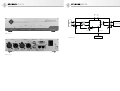
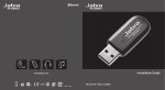
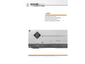
DMI-2
Bedienungsanleitung
digitales Mikrophon-Interface
Operating Instructions
Digital Microphone Interface
georg neumann gmbh · ollenhauerstr. 98 · 13403 berlin · germany
fon +49 (0)30 / 41 77 24-0 · fax -50 · [email protected] · www.neumann.com
2
10
1.
Reparatur- und Servicearbeiten dürfen nur
von erfahrenem und autorisiertem Fachpersonal durchgeführt werden. Wenn Sie die
Geräte eigenmächtig öffnen oder umbauen,
erlischt die Gewährleistung.
Einleitung
In dieser Anleitung finden Sie alle wichtigen Informationen für den Betrieb und die Pflege des
von Ihnen erworbenen Produktes. Lesen Sie diese
Anleitung bitte sorgfältig und vollständig, bevor
Sie das Gerät benutzen. Bewahren Sie die Anleitung bitte so auf, dass sie für alle momentanen
und späteren Nutzer jederzeit zugänglich ist.
• Lassen Sie das Gerät auf Umgebungstemperatur akklimatisieren, bevor Sie es einschalten.
• Nehmen Sie das Gerät nicht in Betrieb, wenn es
beschädigt ist.
• Verlegen Sie Kabel stets so, dass niemand darüber stolpern kann.
• Halten Sie Flüssigkeiten und elektrisch leitfähige Gegenstände, die nicht betriebsbedingt
notwendig sind, von den Geräten und deren
Anschlüssen fern.
• Verwenden Sie zum Reinigen keine Lösungsmittel oder aggressiven Reinigungsmittel.
• Entsorgen Sie die Geräte nach den Bestimmungen Ihres Landes.
Allgemeiner Hinweis: Alle zu Mikrophonen gemachten Angaben beziehen sich auf digitale Mikrophone der Solution-D-Serie von Neumann.
Weitergehende Informationen, insbesondere
auch zu den verfügbaren Zubehörteilen und den
Neumann-Servicepartnern, finden Sie auf unserer
Website www.neumann.com. Die Servicepartner
können Sie auch telefonisch unter +49 (0) 30 /
41 77 24 – 0 erfragen.
Auf unserer Website www.neumann.com finden
Sie in der Rubrik Downloads ergänzend folgende
PDF-Dateien:
• Bedienungsanleitung KM D – digitale Kleinmikrophone
• Bedienungsanleitung D-01 – digitales Großmembran-Mikrophon
• Kurzbeschreibung des AES 42-Standards
Weitergehende Informationen zur Schnittstelle
digitaler Mikrophone finden Sie bei www.aes.org/
standards unter „AES standard for acoustics – Digital interface for microphones“.
Haftungsausschluss:
Die Georg Neumann GmbH übernimmt keinerlei
Haftung für einen Gebrauch des Produkts, der
von den in der Bedienungsanleitung genannten
technischen Voraussetzungen abweicht (z.B. Bedienungsfehler, falsche Spannung, Abweichung
von empfohlenen Korrespondenzgeräten). Dies
gilt auch dann, wenn auf mögliche Schäden bei
abweichendem Gebrauch hingewiesen wurde.
Jegliche Geltendmachung von Schäden und Folgeschäden, die dem Benutzer aufgrund eines solchen abweichenden Gebrauchs entstehen sollten,
wird ausgeschlossen. Ausgenommen von diesem
Haftungsausschluss sind Ansprüche aufgrund des
Produkthaftungsgesetzes.
Zum weltweiten Erfahrungsaustausch unter
Neumann-Anwendern bieten wir das Neumann
Online-Forum an, das sich durch die integrierte
Archivfunktion zu einem umfangreichen KnowHow-Pool entwickelt hat.
2.
Sicherheitshinweise
Der bestimmungsgemäße Gebrauch des Digitalen
Mikrophon-Interfaces DMI-2 ist die Speisung und
Fernsteuerung digitaler Mikrophone nach dem
internationalen Standard AES 42 und die Bereitstellung des Audiodatenstroms vom Mikrophon
für die Aufzeichnung oder Weiterverarbeitung im
AES/EBU-Format.
• Schließen Sie an die Eingänge nur Mikrophone
an, die dem Standard AES 42 entsprechen.
• Verbinden Sie die Ausgänge nur mit AES/EBUEingängen.
Die RJ-45-Buchsen des DMI-2 tragen Gleichspannung und dürfen nicht an ein Ethernet
angeschlossen werden.
D
2
3.
Beschreibung
Das DMI-2 ist ein Speise- und Steuergerät für digitale Mikrophone, die nach dem Standard AES 42
arbeiten (www.aes.org).
Die angeschlossenen Mikrophone werden mit
Strom versorgt und die empfangenen Audiosignale im AES/EBU-Datenformat (AES 3) ausgegeben.
Das DMI-2 stellt die Kommunikation zwischen digitalen Mikrophonen und einem PC/Mac mit der
Neumann-Fernsteuerungssoftware RCS her und
generiert die dazu notwendigen Steuerdaten. Außerdem wird die Synchronisation der Mikrophone
mit einem externen oder dem intern erzeugten
Word Clock durchgeführt.
Sync Locked
Anzeige der Synchronisation des Mikrophons mit
einem Master Word Clock. Die Anzeige blinkt,
während das Mikrophon synchronisiert wird. Sie
leuchtet durchgehend, wenn das Mikrophon erfolgreich synchronisiert ist.
Ext Word Clk
Die wichtigsten Funktionsmerkmale des DMI-2
sind:
• Speisung von zwei digitalen Mikrophonen
(Standard AES 42).
• Empfang des Audiodatenstroms vom Mikrophon und Ausgabe als AES/EBU-Signal.
• Synchronisation der Mikrophone mit einem externen oder dem intern erzeugten Word Clock
(automatische Erkennung).
• Unterstützung aller üblichen Abtastraten:
44,1 / 48 / 88,2 / 96 / 176,4 / 192 kHz.
• Unterstützung des asynchronen Betriebs. Dabei wird der Audiodatenstrom mit der aus dem
Mikrophonsignal rückgewonnenen Abtastrate
am AES/EBU-Ausgang ausgegeben.
• Computerschnittstelle zur Durchleitung und
Verarbeitung bidirektionaler Steuerdaten.
Neumann stellt für diesen Zweck eine Steuersoftware zur Verfügung, die auf PC und Mac
lauffähig ist (Remote Control Software – RCS).
• User Port zur direkten Steuerung (Schaltkontakt bzw. Aktiv-Low-Signal) ausgewählter
Funktionen (Mute, LED1, LED2)
• Mehrere Geräte können kaskadiert werden.
• Interner Speicher: Alle Einstellungen bleiben
nach dem Ausschalten des DMI-2 erhalten.
Nach dem Wiedereinschalten werden diese
Einstellungen wirksam, auch ohne dass eine
Verbindung zum Computer besteht (Standalone-Betrieb).
Anzeigen (Abb. 1)
Power
Anzeige der Betriebsbereitschaft. Während des
Startvorgangs leuchtet die Anzeige mit reduzierter Helligkeit.
Data Valid
Anzeige eines gültigen AES 42-Datenstroms vom
Mikrophon zum DMI-2.
Anzeige eines externen Word Clocks. Die Anzeige ist aus, wenn kein externes Word Clock-Signal
erkannt wird. Die Anzeige blinkt, wenn ein Signal
am externen Word Clock-Eingang anliegt, aber
(noch) keine Synchronisation erreicht ist. Die
Anzeige leuchtet durchgehend, wenn das DMI-2
erfolgreich mit dem externen Word Clock synchronisiert ist. Ein dauerhaftes Blinken der Anzeige bedeutet, dass zwar ein Signal am Word ClockEingang anliegt, welches aber nicht als gültiges
Signal interpretiert wird. Ursache: keine gültige
Word Clock-Frequenz (+/–50 ppm) oder sehr hohe
Jitter-Werte.
Anschlüsse (Abb. 2)
Master Clock In/Out
In digitalen Studioeinrichtungen wird üblicherweise ein zentraler Master Word Clock zur
Synchronisation der angeschlossenen Geräte
verwendet. Das DMI-2 synchronisiert sich auf
diesen externen Word Clock automatisch, sobald
ein solches Signal am Word Clock-Eingang (BNC
– 75 Ohm) erkannt wird.
Liegt kein gültiger Word Clock am Eingang an,
aktiviert das DMI-2 automatisch einen internen
Word Clock-Generator. Die Word Clock-Frequenz
entspricht der Abtastrate der synchron betriebenen Mikrophone (s. Kapitel „Synchronisation“).
Am Anschluss Master Clock (Word Clock) Out
steht daher der empfangene externe bzw. der intern generierte Word Clock für andere Geräte zur
Verfügung.
Auch im stromlosen Zustand des DMI-2 wird
ein externer Word Clock direkt zum Word Clock
Out-Anschluss durchverbunden. Steckt auf der
Ausgangsbuchse des externen Word Clocks kein
Kabel, wird eine automatische Terminierung
(75 Ohm) des Word Clock-Eingangs wirksam.
Ab Hardware-Version 03:
• Als externes Word Clock-Signal kann auch ein
AES 11-Signal verwendet werden.
3
D
• Auch bei externer Synchronisation bleibt der
interne Clock Generator (VCXO) wirksam und
wird mittels einer PLL auf den externen Word
Clock synchronisiert. Hierdurch wird eine sehr
effektive Jitter-Unterdrückung erreicht.
AES 42 In
3-poliger XLR-Eingang zum Anschluss eines digitalen Mikrophons.
AES/EBU Out
3-poliger XLR-Ausgang für das AES/EBU-Ausgangssignal. Zulässige maximale Kabellänge in
Abhängigkeit von der gewählten Abtastrate s. Kapitel „XLR-Kabel“.
Das AES/EBU-Signal enthält standardmäßig 2 Audiokanäle (Stereo links und rechts).
Bei synchronem Betrieb zweier Mono-Mikrophone (s. Kapitel „Synchronisation“) werden die
Audiodaten folgendermaßen auf die Audiokanäle
des AES/EBU-Ausgangssignals verteilt:
• Channel 1 AES/EBU Out
links: Mikrophon 1
rechts: Mikrophon 2
• Channel 2 AES/EBU Out
links: Mikrophon 2
rechts: kein Signal
In allen anderen Fällen gilt folgende Beschaltung:
• Channel 1 AES/EBU Out
links: Mikrophon 1
rechts kein Signal
• Channel 2 AES/EBU Out
links: Mikrophon 2
rechts kein Signal
4
4.
Zur Funktionsweise und Zuordnung der Geräteadressen s. Bedienungsanleitung der Steuerungssoftware RCS.
Achtung: Auf der Gerätefrontseite befindet sich
eine mit „ID“ gekennzeichnete Öffnung. Dahinter
befindet sich ein Drucktaster für diverse künftige
Funktionen. Diese werden u.a. auch eine komfortable Geräteadressierung beinhalten. Zur Zeit ist
dieser Taster noch ohne Funktion.
User Port
Direkte Steuerung von Mikrophonfunktionen
durch externe Schaltkontakte oder Logik-Signale.
Pin 1 Kanal 1 „Light 2“ aus (rote LED, z.Zt. nur im
Solution-D-Mikrophon D-01)
Pin 2 Kanal 1 „Light 1“ aus (blaue LED in Solution-D-Mikrophonen)
Pin 3 Kanal 1 Mute eingeschaltet
Pin 4 reserved
Pin 5 Ground
Pin 6 Kanal 2 „Light 2“ aus (rote LED, z.Zt. nur im
Solution-D-Mikrophon D-01)
Pin 7 Kanal 2 „Light 1“ aus (blaue LED in
Solution-D-Mikrophonen)
Pin 8 Kanal 2 Mute eingeschaltet
Pin 9 reserved
Lieferumfang
•
•
•
•
•
•
•
Achtung: Die Änderung der Geräteadresse soll im
stromlosen Zustand des DMI durchgeführt werden, da die neue Adresse nur beim Einschalten
des Geräts übernommen wird.
RJ-45-Buchsen zum Anschluss eines Steuergeräts, im allgemeinen eines Computers (PC/Mac).
Als Anschlusskabel werden übliche Ethernet(Patch-)Kabel verwendet (Shielded Twisted Pair
– STP oder Unshielded Twisted Pair – UTP).
Die beiden RJ-45-Buchsen sind parallel verbunden, um mehrere DMI-Geräte kaskadieren und
von einem Rechner bedienen zu können.
D
Kodierschalter auf der Geräterückseite zur Einstellung der Geräteadresse. Werden mehrere
DMI-Geräte kaskadiert und gemeinsam gesteuert,
müssen diese unterschiedliche Geräteadressen
(ID) aufweisen. Welche Adressen benutzt werden
dürfen, ist von der verwendeten RCS-Steuerungssoftware abhängig. Zur Zeit sind nur die Adressen
0 … 3 erlaubt. Siehe auch Abschnitt 5, Inbetriebnahme.
Die 9 Pins sind wie folgt belegt (low-aktiv):
Achtung: Die RJ-45-Buchsen des DMI-2 dürfen
nicht an ein Ethernet angeschlossen werden.
Achtung: Die jeweilige Schaltfunktion ist nur
dann aktiviert, wenn in der Steuerungssoftware
(RCS) der User Port für die Kontrolle der jeweiligen Funktion ausgewählt wurde.
ID [Geräteadresse]
Control Bus
Die Datenübertragung entspricht einer RS 485Schnittstelle mit zusätzlichem Power-Anschluss
zur optionalen Versorgung eines externen Steuergeräts.
Die Pins können wahlweise durch Verbinden nach
Ground oder durch Logik-Ausgänge angesteuert
werden (TTL-Logik-Pegel). Zum Beispiel können
für eine Stummschaltung mit einem einzigen Kontakt Mute aktiviert und die rote LED ausgeschaltet
werden (z.B. für „On Air“-Funktion).
Der Anschluss an einen PC oder Mac wird über
deren USB-Port realisiert. Hierzu ist ein USB/RS
485-Converter im Lieferumfang enthalten. Auf
diese Weise wird die Plug&Play-Fähigkeit vorhandener USB-Anschlüsse mit der weitaus größeren möglichen Kabellänge (mind. 100 m) einer
RS 485-Verbindung genutzt.
5.
Digitales Mikrophon Interface DMI-2
USB 485-Konverter
USB-Kabel
RJ-45-Kabel
Netzkabel
Bedienungsanleitung
CD mit RCS-Software und USB-Treibern
Inbetriebnahme
Die folgenden Schritte erläutern die erstmalige
Installation eines digitalen Mikrophonsystems,
bestehend aus Mikrophon, Digitalem MikrophonInterface DMI-2 und Steuerungssoftware RCS.
Installieren Sie zuerst die Steuersoftware RCS
und die zugehörigen Treiber auf Ihrem Computer.
Für den Betrieb der Steuersoftware RCS bestehen an den Computer folgende Mindestanforderungen:
• Computer mit Windows 98 SE, ME, 2000, XP
oder Mac OS mit PPC (ab Version 8.6 und CarbonLib ab Version 1.6),
• ein freier USB-Anschluss,
• 10 MB freier Festplattenspeicher,
• Grafikauflösung 1024 x 768 oder mehr,
• HiColor oder TrueColor,
• CD-ROM-Laufwerk,
• Maus und Tastatur,
• Adobe Acrobat Reader (nur für Online Manual)
Starten Sie die SETUP-Routine auf der beigefügten CD-ROM (Windows: „Setup“, Mac OS: „Install RCS“) und folgen Sie den Anweisungen auf
dem Bildschirm.
Achtung:
• Für die Installation unter Windows 2000/XP
bzw. Mac OS X sind Administratorrechte erforderlich.
• Der Konverter USB 485 darf erst mit einem
USB-Port des Computers verbunden werden,
nachdem die RCS installiert wurde.
USB-Treiberinstallation
Nachdem die RCS installiert wurde, muss der
Schnittstellenkonverter USB 485 mit einem USBAnschluss des Computers verbunden werden.
Auf diese Weise ist sichergestellt, dass der mitgelieferte USB-Treiber, der für den Betrieb des
Konverters erforderlich ist, geladen wird. Falls
unter Windows nach dem Speicherort der Treiberdateien gefragt wird, ist das CD-ROM-Laufwerk
auszuwählen. Vor dem Bestätigen muss sichergestellt sein, dass sich die Installations-CD-ROM im
Laufwerk befindet.
Weitere Verbindungen
Verbinden Sie den USB 485-Konverter über PatchKabel mit einer der RJ-45-Buchsen (Control Bus)
des DMI-2.
Wählen Sie die Geräteadresse (ID) am DMI-2
(Kodierschalter an der Rückseite des DMI). Die
Adressvergabe sollte bei „0“ beginnen. Es werden
zur Zeit die Adressen 0 ... 3 von der RCS unterstützt.
Achtung: Erkennung der ID nur während des
Einschaltvorgangs des DMI-2; daher nach Änderung der ID Stromversorgung kurz unterbrechen.
(s. Abschnitt „ID“, Seite 4)
Stellen Sie die Verbindung zwischen Mikrophon,
DMI-2 und dem nachfolgenden Gerät (z.B. Mischpult) über XLR-Kabel (s. „Kabel“) her.
Soll das DMI und die angeschlossenen Mikrophone mit einem externen Master Word Clock
synchronisiert werden, so verbinden Sie diesen
über ein BNC-Kabel mit dem Word Clock Eingang
des DMI-2.
Bei Verwendung mehrerer DMIs können diese
über den Steuerbus kaskadiert werden. Dazu wird
ein RJ-45-Patchkabel in die zweite RJ-45-Buchse
des DMI gesteckt und mit einer der RJ-45-Buchsen
des zweiten DMI verbunden usw. Gegebenenfalls
leiten Sie auch den Word Clock über die BNC-Ausgangsbuchse an weitere DMIs weiter.
Schließen Sie das DMI-2 an das Stromnetz an.
5
D
Starten Sie die RCS – gegebenenfalls erneut, falls
das Programm noch geöffnet war.
Achtung: Das DMI-2 muss immer eingeschaltet
sein, bevor die RCS gestartet wird, damit das
DMI-2 vom PC/Mac erkannt wird. Solange die RCS
arbeitet, darf das Verbindungskabel zwischen
Computer und USB 485-Konverter nicht abgezogen werden, um ein unkontrolliertes Verhalten
des Computers zu vermeiden. Dies ergibt sich aus
der Spezifikation der USB-Schnittstelle.
Lange Modulationskabel und mehrfache Steckverbindungen führen zu einem Spannungsabfall
der Mikrophonspeisespannung und zu einer Verschlechterung des Jitter-Verhaltens insbesondere
bei hohen Abstastraten. Verwenden Sie daher
möglichst durchgehende Kabelverbindungen
zwischen Mikrophon und DMI-2 bzw. DMI-2 und
dem Folgegerät und bei größeren Distanzen ausschließlich AES/EBU-Kabel (Wellenwiderstand
110 Ohm).
Achten Sie darauf, dass das Mikrophon und alle
Geräte der digitalen Signalkette synchronisiert
sind. Am Digitalen Mikrophon-Interface von Neumann angeschlossene Mikrophone sollten immer
im Synchronmodus betrieben werden, unabhängig davon, ob in der nachfolgenden Signalkette
Sample-Rate-Converter im Einsatz sind. Auf diese
Weise wird im DMI eine sehr effektive Jitter-Unterdrückung wirksam (ab Hardware-Version 03).
Auch ist die Ausgabe zweier Mikrophonsignale in
einem AES 3-Stereosignal nur möglich, wenn die
Mikrophone untereinander synchron laufen.
Achten Sie beim Anschließen von Kabeln auf die
korrekte Verriegelung der Steckverbinder.
Verlegen Sie die Kabel so, dass sie keine Stolpergefahr darstellen.
Software-Update
Die Software im DMI-2 und in Neumann-Mikrophonen ist update-fähig. Zukünftige Updates
können ohne Öffnen des Geräts über die Steuerungssoftware RCS durchgeführt werden (s. Bedienungsanleitung RCS).
6.
Außerbetriebnahme
Verringern Sie vor dem Abschalten von Mikrophonen und Abziehen von Kabeln den Lautstärkepegel Ihres weiterverarbeitenden Gerätes.
Ziehen Sie beim Lösen von Kabeln stets nur an
den Steckverbindern und nicht am Kabel.
7.
1)
Zulässige klimatische Verhältnisse:
Betriebstemperaturbereich...............0 °C … +45 °C
Lagerungstemperaturbereich ...... –20 °C … +70 °C
Feuchtebereich ....................... max. 90 % rel. hum.
bei +20 °C
Eingänge ...........................2x XLR 3 F nach AES 42,
Audiodaten entsprechend
AES/EBU- (AES 3-) Datenformat,
Phantomspeisung (DPP),
Fernsteuerdaten
Phantomspeisung
(DPP) ..................... +10 V, max. 250 mA pro Kanal,
kurzschlussfest
Fernsteuerdaten ........................... Pulse (+2 V), der
Phantomspeisung
überlagert, ca. 750 Bit/s
Ausgänge ............... 2x XLR 3 M, AES/EBU- (AES 3-)
Datenformat
Unterstützte Abtastraten .......................44,1 / 48 /
88,2 / 96 kHz /
176,4 kHz*/ 192 kHz*
Synchronisation ........................... AES 42 – Mode 1
und Mode 2
Mode 1 .................................. Asynchroner Mode,
Mikrophon-Clock freilaufend
auf gewählter Word Clock-Frequenz –
bedingt Sample-Rate-Converter
(SRC) auf Empfängerseite
Mode 2 ................................... Synchroner Mode,
Taktnachregelung durch PLL.
Bei fehlendem externen Word Clock
wird automatisch der interne
Word Clock-Generator aktiviert.
Word Clock Input ..............................................BNC
Vin .......................................>250 mV an 75 Ohm
Word Clock Output ............................................BNC
Vout ......................................... ca. 2 V an 75 Ohm
Interner Word ClockGenerator ....................... 44,1 / 48 / 88,2 / 96 kHz
176,4*/ 192 kHz 2)
Genauigkeit ................................................ ±25 ppm
Anzeigen......................................................... Power
Data Valid (Mikrophon),
Sync Locked,
Ext Word Clock
1)
2)
D
6
Control Bus ................................2x RJ-45-Buchsen,
Verbindung zum USB-Port
des Computers über
Neumann-Schnittstellenkonverter USB 485,
für Kaskadierungszwecke
parallel verbunden.
Datenformat:...................RS 485 mit zusätzlichem
Power-Out-Pin (ca. +11,3 V)
Geräteadresse (ID) ...................................... 0 ... 15,
einstellbar mit
Kodierschalter
an der Geräterückseite.
User Port ............................................. 9-pol Sub-D,
3 Schaltfunktionen pro Kanal
Stromversorgung ............... 90 ... 240 V, 50/60 Hz
Leistungsaufnahme .....................................< 30 VA
Abmessungen .......... (B x H x T) 218 x 56 x 163 mm
Gewicht .....................................................ca. 1,4 kg
Technische Daten
8.
Zusatzerläuterungen
8.1 AES 42
Der Standard basiert auf der Verwendung 2-adriger symmetrischer Kabel (AES/EBU-Kabel – bei
kurzen Verbindungen auch herkömmliche Analogkabel). Die Stromversorgung digitaler Mikrophone ist als Digital Phantom Power (DPP) von
+10 V, max. 250 mA definiert. Durch Modulation
der Phantomspannung wird ein Fernsteuerdatenstrom in Richtung Mikrophon erzeugt (+2 V-Pulse).
Das Datenformat des vom Mikrophon gesendeten
digitalen Audiosignals entspricht dem Standard
AES/EBU (AES 3). Die in diesem Standard defi nierten Userbits sind zur Übertragung diverser
Informationen vorgesehen. Im Standard AES 42
sind diese Userbits in ihrer Bedeutung für digitale Mikrophone definiert. Im DMI-2 werden diese
Daten vom Audiosignal getrennt und zum Control
Bus (Schnittstelle für Computer oder Steuergerät)
geleitet.
Abb. 3 zeigt ein einfaches Funktionsdiagramm
eines Mikrophon-Interfaces mit AES 42-Eingang
und AES/EBU-Ausgang.
8.2 XLR-Kabel
Die realisierbare Leitungslänge von einem digitalen Neumann-Mikrophon zum DMI-2 hängt von
dem verwendeten Kabeltyp und von der gewähl-
ten Sampling-Rate (Word Clock-Frequenz) ab. Bei
Längen bis zu 100 m bei 44,1/48 kHz-Abtastrate
können hochwertige „analoge“ XLR 3-Kabel (z.B.
IC 3 von Neumann) verwendet werden. Für größere Leitungslängen wird die Verwendung von AES/
EBU-Kabeln (110 Ohm) erforderlich. Typischerweise können in diesem Fall Längen bis 300 m
(Abtastrate 44,1/48 kHz) bzw. 200 m (Abtastrate
88,2/96 kHz) bzw. 100 m (Abtastrate 176,4/192
kHz) realisiert werden.
Achtung: Bei längeren Verbindungen zwischen
Mikrophon und DMI-2 muss bei der Auswahl der
Kabel darauf geachtet werden, dass der DC-Widerstand einen maximalen Wert nicht überschreitet.
Dies ist nötig, um unzulässigen Spannungsabfall
der Phantomspeisung zu vermeiden. Es gilt folgendes:
Ra/2 + Rs < 18 Ohm
Ra = DC-Widerstand der einzelnen Ader,
Rs = DC-Widerstand des Schirms bzw. der
GND-Rückleitung.
Die realisierbare Leitungslänge vom DMI-2 zum
nachfolgenden Gerät (z.B. digitales Mischpult)
hängt maßgeblich von den technischen Eigenschaften des nachfolgenden Geräts ab. Hierzu
können keine spezifi schen Aussagen gemacht
werden. Im Zweifel ist die Verwendung von AES/
EBU-Kabeln (110 Ohm) empfehlenswert.
8.3 Betrieb ohne Steuerungssoftware RCS
Sämtliche Einstellungen, die beim Ausschalten
des DMI-2 wirksam sind, werden intern gespeichert und nach dem Wiedereinschalten automatisch in das Mikrophon geladen. Die letzten Mikrophoneinstellungen werden wiederhergestellt,
ohne dass hierfür eine Verbindung zum Steuergerät (PC/Mac) nötig ist.
Dies geschieht auch, wenn ein Mikrophon erst
später an das schon eingeschaltete DMI-2 angeschlossen wird.
Beim Starten der Steuerungssoftware RCS wird
die dort gespeicherte Konfiguration aller Mikrophonkanäle mit den im DMI-2 gespeicherten
Einstellungen verglichen. Werden Unterschiede
erkannt, wird in einem Auswahl-Menü abgefragt,
welche Konfiguration übernommen werden soll
(s. Bedienungsanleitung RCS).
Alle Werte für nicht-kondensierende Feuchtigkeit.
nur DMI-2 ab Hardware-Version 03
7
D
8.4 Synchronisation
Der Standard AES 42 beschreibt zwei Arten der
Synchronisation des Mikrophons mit dem Empfänger (z.B. Mischpult oder Digitales MikrophonInterface – DMI-2):
Mode 1: Das Mikrophon arbeitet unsynchronisiert
mit der Abtastrate seines internen Quarzoszillators und benötigt auf der Empfängerseite einen
Abtastratenwandler (Sample-Rate-Converter).
Achtung: Dieser Modus sollte nur benutzt werden, wenn Synchronisation nach Mode 2 nicht
möglich ist, da übliche Sample-Rate-Converter
die Signalqualität verschlechtern (Dynamikumfang, Latenzzeit).
9.
D
8
Mode 2: Das Mikrophon arbeitet synchron zu
einem Master Word Clock. Dies kann ein externer oder der interne Word Clock des DMI-2 sein.
Hierbei wird im AES 42-Empfänger (DMI-2) ein
Frequenz/Phasenvergleich mit dem Master Word
Clock durchgeführt. Es wird ein Steuersignal erzeugt, das über den Fernsteuerdatenstrom zum
Mikrophon übertragen wird und dort die Frequenz
des internen Quarzoszillators steuert.
Fehler
▶ Mögliche Ursachen
▶ Abhilfe
LED „DATA VALID“ leuchtet nicht,
obwohl ein Mikrophon angeschlossen und eingeschaltet ist (RCS-Anzeige „AES42 PWR“ leuchtet).
Kein gültiger Datenstrom - Ursache:
Kabelverbindung auf Unterbrechung prüfen.
Kabelverbindung zum Mikrophon
mangelhaft oder zu lang
Die für die gewählte Word Clk
Frequenz geltenden Grenzen
hinsichtlich max. Kabellängen
und erforderlicher Kabelqualität
beachten. Unnötige Übergangsstellen (Steckverbindungen) vermeiden. Siehe Kapitel 8.2, Kabel.
Der interne Word Clock-Generator kann über die
BNC-Ausgangsbuchse zur Synchronisation weiterer DMIs und der weiterverarbeitenden Geräte
(z.B. Mischpult) verwendet werden.
Fehlercheckliste
Fehler
▶ Mögliche Ursachen
Ein am DMI angeschlossenes
und eingeschaltetes Mikrophon
wird an der RCS nicht angezeigt,
obwohl LED “DATA VALID“ am DMI
leuchtet.
DMI wird von der RCS Software
nicht erkannt – Ursache:
▶ Abhilfe
Das DMI war beim Starten der RCS
noch nicht eingeschaltet.
RCS erst starten, nachdem das
DMI eingeschaltet wurde oder
Befehl Options/DMI ausführen und
Fenster wieder schliessen.
Eine derzeit von der RCS nicht
unterstützte ID oder Verwendung derselben ID bei mehreren
Geräten.
Derzeitig wird nur eine ID im
Bereich 0 … 3 unterstützt. Einstellung durch Kodierschalter auf der
Geräte-Rückseite, für jedes Gerät
eine andere ID !
ID bei laufendem Betrieb geändert.
DMI muss nach einer ID -Änderung
neu eingeschaltet werden, danach
RCS neu starten oder Befehl Options/DMI ausführen und Fenster
wieder schliessen.
Falsche Einstellung für Schnittstelle (USB, COM1, COM2).
Richtige Schnittstelle in RCS über
Options/Communication wählen.
LED „Ext. Word Clk“ leuchtet
nicht, obwohl ein Ext. Word Clk
angeschlossen ist.
Es wird kein Word Clk – Signal
erkannt.
Word Clock Quelle und Kabelverbindung überprüfen.
LED „Ext. Word Clk“ blinkt dauerhaft (kurzzeitiges Blinken nach
Aktivierung eines Ext. Word Clk ist
normal und zeigt den Synchronisationsprozess an).
Word Clock Signal liegt an, wird
aber nicht als gültiges Signal interpretiert. Word Clock Frequenz
weicht z.B. mehr als ± 50 ppm vom
Sollwert ab.
Word Clock Frequenz überprüfen,
andere Quelle für Word Clock
wählen. Alternativ Ext. Word
Clk entfernen und DMI als Word
Clk Master für die Signalkette
verwenden.
Mikrophon defekt.
Anderes Mikrophon verwenden.
LED „SYNC LOCKED“ blinkt dauerhaft (kurzzeitiges Blinken während
des Sychronisationsvorgangs ist
normal).
Mikrophon wird nicht synchronisiert, weil die Word Clk - Frequenz
nicht unterstützt wird.
Eine Word Clk Frequenz auswählen, die von allen angeschlossenen
Mikrophonen unterstützt wird.
LED „SYNC LOCKED“ leuchtet nicht.
Mikrophon arbeitet im asynchronen Modus (ist im Word Clk-Fenster der RCS durch den Buchstaben
‚a‘ vor der Frequenzanzeige zu
erkennen).
Samplerate für Synchronmodus
bzw. „Sync to Ext. Word Clk“
einstellen.
Mikrophon unterstützt nur „Mode
1“ nach AES 42-Standard, d.h. es
ist nicht synchronisierbar.
Synchronisierbares Mikrophon
verwenden (alle Neumann-Mikrophone der Solution-D-Serie).
Steuerung von Funktionen über User User Port-Steuerung nicht freigePort funktioniert nicht.
geben.
Im Systemmenü der RCS Software
muss „Function controlled by
Userport“ für die gewünschte
Funktion aktiviert sein.
9
D
1.
Repairs and servicing are to be carried
out only by experienced, authorized service personnel. Unauthorized opening or
modification of the equipment shall void
the warranty.
Introduction
This manual contains essential information for the
operation and care of the product you have purchased. Please read the instructions carefully and
completely before using the equipment. Please
keep this manual where it will be accessible at all
times to all current and future users.
• Allow the equipment to adjust to the ambient
temperature before switching it on.
• Do not operate the equipment in a damaged
condition.
• Always run cables in such a way that there is no
risk of tripping over them.
• Ensure that liquids and electrically conductive
objects unless required for operation are kept
at a safe distance from the equipment and its
connections.
• Do not use solvents or aggressive cleansers for
cleaning purposes.
• Dispose of the equipment in accordance with
the regulations applicable to the respective
country.
Please note: All information relating to the microphones refers to digital microphones of the Neumann Solution-D series.
Additional information, in particular concerning available accessories and Neumann service
partners, can be found on our website: www.neumann.com. Information about service partners
can also be obtained by telephone: +49 (0) 30 /
41 77 24 - 0.
The following related files are available in PDF
format in the Downloads section of our website
www.neumann.com:
• KM D Operating Manual – Digital Miniature Microphones
• D-01 Operating Manual – Digital Large-Diaphragm Microphone
• Brief Description of the AES 42 Standard
Additional information concerning the digital microphone interface can be found at http://www.
aes.org/publications/standards/ under the title
“AES standard for acoustics – Digital interface for
microphones”.
Disclaimer:
The product is sold “as-is” and the customer is assuming the entire risk as to the product’s suitability for his needs, its quality and its performance.
In no event will Neumann be liable for direct,
indirect, special, incidental or consequential damages resulting from any defect in the product or
from its use in conjunction with any microphones/
products from other manufacturers, even if advised of the possibility of such damages.
The Neumann online forum enables Neumann
users worldwide to share their experiences.
Through its integrated archive function, the forum
has developed into an extensive knowledge pool.
2.
Safety instructions
The DMI-2 Digital Microphone Interface has the
intended purpose of providing power and remote
control for digital microphones in accordance
with the international standard AES 42, and of
making the audio data stream from the microphone available in AES/EBU format for recording
or further processing.
• Connect to the inputs only microphones that
comply with the AES 42 standard.
• Connect the outputs only to AES/EBU inputs.
The RJ-45 ports of the DMI-2 have a DC
voltage, and must not be connected to an
Ethernet.
US
GB
10
The most important functional features of the
DMI-2 are as follows.
• Power is supplied to two digital microphones
(in accordance with the AES 42 standard).
• The audio data stream is received from the microphone and is output as an AES/EBU signal.
• The microphone is synchronized with an external or internally generated word clock (using
automatic detection).
• All standard sampling rates are supported:
44.1 kHz, 48 kHz, 88.2 kHz, 96 kHz, 176.4 kHz,
and 192 kHz.
• Asynchronous operation is supported. In this
case the audio data stream is made available
at the AES/EBU output with the sampling rate
recovered from the microphone signal.
• A computer interface is provided for transmitting and processing bidirectional control data.
For this purpose, Neumann supplies control
software that can be operated on a PC or Mac
(the RCS Remote Control Software).
• The user port provides for direct control (via a
switch contact or low-active signal) of selected
functions (Mute, LED 1 and LED 2).
• Multiple devices can be cascaded.
• Internal memory: All settings are retained after the DMI-2 has been switched off. After it is
switched on again, these settings remain in effect even in the absence of a connection to the
computer [stand-alone operation].
Indicators (Fig. 1)
Power
3.
Description
The DMI-2 provides power and remote control for
digital microphones that operate in accordance
with the AES 42 standard (see www.aes.org).
Connected microphones are supplied with power,
and the audio signals received are output in the
AES/EBU data format (AES 3).
The DMI-2 provides for communication between
digital microphones and a PC/Mac with the Neumann RCS remote control software, and generates
the required control data. In addition, synchronization of the microphones is carried out via an
external or internally generated word clock.
Indicates that the equipment is ready for operation. During the startup process, the indicator
shines less brightly.
Data Valid
Indicates a valid AES 42 data stream from the microphone to the DMI-2.
Sync Locked
Indicates synchronization of the microphone with
a master word clock. The indicator blinks while
the microphone is being synchronized. It shines
continuously when the microphone has been successfully synchronized.
Ext Word Clk
Indicates an external word clock. The indicator
does not light up if no external word clock signal
is detected. The indicator blinks if a signal is present at the external work clock input but synchronization has not (yet) been achieved. The indicator shines continuously when the DMI-2 has been
successfully synchronized with the external word
clock. Prolonged blinking of the indicator means
that although a signal is present at the word clock
input, it has not been interpreted as a valid signal;
the cause may be an invalid word clock frequency
(+/-50 ppm) or very high jitter values.
Ports (Fig. 2)
Master Clock In/Out
In digital studio setups, a central master word
clock is usually used for synchronizing the connected equipment. The DMI-2 automatically synchronizes itself with this external word clock as
soon as such a signal is detected at the word clock
input (BNC, 75 ohms).
If there is no valid word clock signal at the input,
the DMI-2 automatically activates an internal
word clock generator. The word clock frequency
corresponds to the sampling rate of the synchronously operated microphones (see “Synchronization” section). The signal provided for other
equipment at the Master Clock Out word clock
port is therefore the external word clock signal
that has been received or the internally generated
word clock signal.
Even in the absence of power, an external word
clock signal will be transferred by the DMI-2 directly to the Master Clock Out port. If no cable has
been attached to the output of the external word
clock, an automatic termination (75 ohms) is effective at the word clock input.
For hardware version 03 or above:
• An AES 11 signal can also be used as an external word clock signal.
• Even in the case of external synchronization,
the internal (VCXO) clock generator remains
active and is synchronized with the external
word clock by means of a phase-locked loop
(PLL). This provides very effective jitter suppression.
11
US
GB
AES 42 In
This is a 3-pin XLR input for connecting a digital
microphone.
purpose. This permits use of the plug-and-play capability of available USB ports together with the
much longer cable lengths (at least 100 m) that
are possible with an RS 485 connection.
The pins can be controlled via contact with
ground, or alternatively by means of logic outputs
(TTL logic level). For example, in the case of muting, the mute can be activated and the red LED
switched off via a single contact (e.g. for the “On
Air” function).
AES/EBU Out
This is a 3-pin XLR output for the AES/EBU output
signal. See the “XLR cables” section for permissible maximum cable lengths depending upon the
selected sampling rate.
The AES/EBU signal includes 2 standard audio
channels (stereo left and right).
In the case of synchronous operation with two
mono microphones (see “Synchronization” section), the audio data are distributed as follows between the audio channels of the AES/EBU output
signal:
• Channel 1 AES/EBU Out
Left: Microphone 1
Right: Microphone 2
• Channel 2 AES/EBU Out
Left: Microphone 2
Right: No signal
In all other cases, the following assignment applies:
• Channel 1 AES/EBU Out
Left: Microphone 1
Right: No signal
• Channel 2 AES/EBU Out
Left: Microphone 2
Right: No signal
Control Bus
RJ-45 ports are provided for connecting a control
device, which is generally a computer (PC or Mac).
Standard Ethernet (patch) cables are used as connecting cables: Shielded Twisted Pair (STP) or Unshielded Twisted Pair (UTP).
Data transfer is effected via an RS 485 interface
with an additional power-out pin, for the optional
supply of an external control device.
Attention: The RJ-45 ports of the DMI-2 must not
be connected to an Ethernet.
The two RJ-45 ports are connected in parallel, in
order to permit cascading and computer operation with multiple DMI devices.
The DMI-2 is connected to the USB port of a PC or
Mac. A USB/RS 485 converter is supplied for this
US
GB
12
ID [device address]
The device address is set by means of a coding
switch on the back of the device. If multiple DMI
devices are cascaded and controlled together,
they must have different device addresses (IDs).
The addresses that can be used are dependent
upon the RCS control software employed. Currently, only the addresses 0, 1, 2 and 3 are permitted (see also Section 5, “Setup”).
Attention: The respective switch function is activated only when “User Port” has been selected
in the RCS control software for the control of the
relevant function.
4.
•
•
•
•
•
•
•
Attention: The device address should be changed
when the DMI is not supplied with power, since
the new address will not take effect until the next
time the device is switched on.
Please see the RCS control software operating
manual for information concerning the mode of
operation and assignment of device addresses.
Attention: On the front of the device is an opening labelled “ID”. Here there is a push-button for
various future functions, which will include a
convenient means of setting the device address.
However, at present this button is not yet operational.
Equipment supplied
5.
DMI-2 Digital Microphone Interface
USB 485 converter
USB cable
RJ-45 cable
Power cable
Operating manual
CD with RCS software and USB driver
Setup
The following steps are to be carried out for the
initial installation of a digital microphone system
consisting of the microphone, the DMI-2 Digital
Microphone Interface, and the RCS control software.
User Port
First install the RCS control software and the associated drivers on your computer.
This permits direct control of microphone functions by means of external switch contacts or
logic signals.
The minimum requirements for operation of the
RCS control software on the computer are:
The assignments of the 9 pins are as follows (lowactive):
Pin 1 Channel 1 “Light 2” off (red LED, currently
only for the D-01 Solution-D microphone)
Pin 2 Channel 1 “Light 1” off (blue LED of Solution-D microphones)
Pin 3 Channel 1 mute switched on
Pin 4 Reserved
Pin 5 Ground
Pin 6 Channel 2 “Light 2” off (red LED, currently
only for the D-01 Solution-D microphone)
Pin 7 Channel 2 “Light 1” off (blue LED of Solution-D microphones)
Pin 8 Channel 2 mute switched on
Pin 9 Reserved
• Computer with Windows 98 SE, ME, 2000 or
XP operating system, or Mac OS with PPC (version 8.6 or higher, and CarbonLib version 1.6
or higher)
• A free USB port
• 10 MB of free hard disk space
• Graphics resolution of 1024 x 768 or more
• HiColor or TrueColor
• CD-ROM drive
• Mouse and keyboard
• Adobe Acrobat Reader (only for the online
manual)
Start the setup program on the accompanying
CD-ROM (Windows: “Setup”; Mac OS: “Install
RCS”) and follow the instructions displayed on
the screen.
Attention:
• Administrator rights are required for installation with Windows 2000/XP or Mac OS X.
• The USB 485 converter must not be attached to
a computer USB port until after the RCS software has been installed.
USB driver installation
After the RCS has been installed, the USB 485
interface converter must be connected to a computer USB port. This ensures loading of the supplied USB driver, which is required for operation
of the converter. In the Windows operating system, if there is a query regarding the storage location of the driver files, the CD-ROM drive should
be selected. Before confirmation, ensure that the
installation CD-ROM has been inserted into the
drive.
Other connections
Using a patch cable, connect the USB 485 converter to one of the RJ-45 ports (control bus) of
the DMI-2.
Set the device address (ID) of the DMI-2 (using
the coding switch on the back of the DMI). Addresses should be assigned beginning with “0”.
The addresses 0 to 3 are currently supported by
the RCS.
Attention: The ID is detected only during startup
of the DMI-2. Therefore, switch the power supply
off and then back on again after changing the ID,
so that the change will be detected. (Refer to the
“ID” section, page 11)
Connect the microphone, the DMI-2 and the subsequent device (e.g. mixing console) by means of
XLR cables (see “XLR cables” section).
If the DMI and the connected microphones are
to be synchronized with an external master word
clock, use a BNC cable to connect the master word
clock port to the Word Clock input of the DMI-2.
If multiple DMIs are used, they can be cascaded
via the control bus. For this purpose, use an RJ45 patch cable to connect the second RJ-45 port
of the initial DMI to one of the RJ-45 ports of the
second DMI, etc.
If necessary, also transfer the word clock signal to
additional DMIs, via the BNC output. Connect the
DMI-2 to the power supply network.
13
US
GB
Start the RCS program, or if necessary restart it, if
the program was already on.
Attention: The DMI-2 must always be switched on
before the RCS is started, so that the DMI-2 will be
detected by the PC or Mac. While the RCS is operating, the cable connecting the computer to the
USB 485 converter must not be disconnected, so
as to prevent uncontrolled behavior of the computer. This requirement is due to the specifications of the USB interface.
Long modulation cables and multiple connections
lead to a drop in the microphone supply voltage
and to a deterioration of jitter behavior, particularly in the case of high sampling rates. Therefore,
if possible, use continuous cable between the microphone and the DMI-2, and between the DMI-2
and subsequent equipment. For longer distances
use AES/EBU cable exclusively (with an impedance level of 110 ohms).
Ensure that the microphone and all devices in
the digital signal chain are synchronized. Microphones connected to the Neumann Digital Microphone Interface should always be operated in synchronous mode, whether or not sample rate converters are used in the subsequent signal chain.
This permits very effective jitter suppression in
the DMI (for hardware version 03 or above). In
addition, the output of two microphone signals as
an AES 3 stereo signal is possible only if the microphones are synchronized with one another.
When connecting cables, ensure that the connectors are locked correctly.
Run the cables in such a way that there is no risk
of tripping over them.
Software updating
The software in the DMI-2 and in Neumann microphones is updatable. Future updates can be carried out without opening the device, via the RCS
control software (see RCS Operating Manual).
6.
Shutdown
Before switching off the microphones or disconnecting the cables, reduce the volume of connected equipment.
When disconnecting a cable, always pull only on
the connector and not on the cable itself.
7.
1)
Permissible atmospheric conditions
Operating temperature .....................0 °C to +45 °C
Storage temperature .....................–20 °C to +70 °C
Relative humidity ................... max. 90 % at +20 °C
Inputs: ............2 x XLR 3 F complying with AES 42,
Audio data in accordance with
AES/EBU (AES 3) data format,
Phantom power (DPP),
Remote control data
Phantom power
(DPP): .................+10 V, max. 250 mA per channel,
short-circuit protected
Remote control data: ......................... Pulses (+2 V),
superimposed on the
phantom power,
approx. 750 bits/s
Outputs: ............................... 2 x XLR 3 M, AES/EBU
(AES 3) data format
Sampling rates supported: ........ 44.1 kHz, 48 kHz,
88.2 kHz, 96 kHz,
176.4 kHz*, 192 kHz*
Synchronization: .......................... AES 42 – Mode 1
and Mode 2
Mode 1:.............................. Asynchronous mode,
microphone clock free-running
at selected word clock frequency;
a sample rate converter (SRC)
is required at the receiver
Mode 2: ............................... Synchronous mode,
clock control effected via PLL.
If there is no external word clock,
the internal word clock generator
is automatically activated.
Word clock input ...............................................BNC
Vin ....................................... >250 mV at 75 ohms
Word clock output .............................................BNC
Vout .................................approx. 2 V at 75 ohms
Internal word clock
generator:.................................... 44.1 kHz, 48 kHz,
88.2 kHz, 96 kHz,
176.4 kHz*, 192 kHz 2)
Accuracy:.................................................... ±25 ppm
Indicators:...................................................... Power
Data Valid (microphone),
Sync Locked,
Ext Word Clock
1)
US
GB
2)
14
Control bus: ....................................2 x RJ-45 ports;
connection to computer USB port
via the Neumann USB 485
interface converter;
connected in parallel
for the purpose of cascading
Data format: .......................RS 485 with additional
power-out pin (approx. +11.3 V)
Device address (ID): ........... 0 to 15, adjustable via
coding switch on the back
of the device
User port: .............................................9-pin sub-D,
3 switch functions per channel
Power supply: .................90 V to 240 V; 50/60 Hz
Power consumption: .................................... <30 VA
Dimensions: .............. (W x H x D) 218 mm x 56 mm
x 163 mm
Weight: ..............................................approx. 1.4 kg
Technical data
All values are for non-condensing moisture.
only for DMI-2, hardware version 03 or above
(word clock frequency) selected. For cable lengths
of up to 100 m with a sampling rate of 44.1 kHz or
48 kHz, high-quality “analog” XLR 3 cable (e.g.
the IC 3 cable supplied by Neumann) can be used.
For greater cable lengths, the use of AES/EBU cables [110 ohms] is required. If AES/EBU cables are
employed, the following cable lengths can typically be used: Up to 300 m with a sampling rate of
44.1 kHz or 48 kHz; 200 m with a sampling rate of
88.2 kHz or 96 kHz; 100 m with a sampling rate of
176.4 kHz or 192 kHz.
Attention: If long cables are used to connect the
microphone with the DMI-2, the DC resistance of
the cables must not exceed a certain maximum
value, since an excessive DC resistance would result in an impermissible voltage drop in the phantom power. The following formula applies:
Rc/2 + Rs < 18 ohms
8.
Additional information
8.1 AES 42
This standard is based upon the use of a 2-line
balanced cable (AES/EBU cable; for short connections conventional analog cable can also be
used). The power supply for digital microphones
is defined as Digital Phantom Power (DPP) with
+10 V and max. 250 mA. Modulation of the phantom voltage generates a remote control data
stream which is transmitted to the microphone
(as +2 V pulses).
The data format of the digital audio signal transmitted from the microphone complies with the
AES/EBU (AES 3) standard. The user bits defined
in this standard are intended for the transmission
of various types of information. The AES 42 standard defines the significance of these user bits
with regard to digital microphones. In the DMI-2,
these data are separated from the audio signal
and are transferred to the control bus, which
serves as an interface for a computer or control
device.
Fig. 3 shows a simple functional diagram of a microphone interface with an AES 42 input and an
AES/EBU output.
8.2 XLR cables
The length of cable that can be used from a digital
Neumann microphone to the DMI-2 is dependent
upon the type of cable and upon the sampling rate
Rc = DC resistance of the individual cable
core,
Rs = DC resistance of the shield or the GND
return line.
The length of cable that can be used from the DMI-2
to subsequent equipment (e.g. a digital mixing
console) is substantially dependent upon the
technical features of the subsequent equipment.
Thus no specific statements can be made concerning the cable length. In case of doubt, the use of
AES/EBU cables [110 ohms] is recommended.
8.3 Operation without the RCS control software
All of the settings which are in effect when the
DMI-2 is switched off are stored internally, and
are automatically sent to the microphone when
the equipment is switched on again. The most
recent microphone settings are restored, without
requiring a connection to the control device (PC
or Mac).
The same procedure is followed if a microphone is
connected to the DMI-2 later, after the DMI-2 has
already been switched on.
When the RCS control software is started, the configurations stored there for all of the microphone
channels are compared with the settings stored in
the DMI-2. If differences are detected, a menu is
displayed that asks which configuration is to be
used (see RCS Operating Manual).
15
US
GB
8.4 Synchronization
The AES42 standard describes the following two
modes for synchronizing the microphone with the
receiver (e.g. a mixing console or the DMI-2 Digital Microphone Interface).
Mode 1: The microphone operates asynchronously, using the sampling rate of its internal quartz
oscillator. In this case, a sample rate converter is
required at the receiver.
Attention: This mode should be used only when
it is not possible to use mode 2 synchronization, since signal quality can be expected to be
impaired by standard sample rate converters (in
terms of dynamic range and latency time).
9.
US
GB
Mode 2: The microphone operates synchronously
with a master word clock. This can be an external word clock, or the internal word clock of the
DMI-2. In this case, a frequency/phase comparison with the master word clock is carried out in
the AES 42 receiver. A control signal is generated
which is transmitted via the remote control data
stream to the microphone, where it controls the
frequency of the internal quartz oscillator.
▶ Possible causes
▶ Solution
No valid data stream – Cause:
Check to ensure a continuous
cable connection.
Via the BNC output, the internal word clock generator can be used to synchronize additional
DMIs and connected equipment, such as a mixing
console.
Troubleshooting
Problem
▶ Possible causes
The RCS does not indicate that a
microphone is switched on and
connected to the DMI, even though
the “DATA VALID” LED on the DMI
is lit up.
The DMI is not recognized by the
RCS software. – Cause:
▶ Solution
The DMI was not switched on
at the time when the RCS was
started.
Do not start the RCS until the DMI
has been switched on; or execute
the command Options/DMI and
then close the window again.
An ID has been used that is not
currently supported by the RCS,
or the same ID has been used for
more than one DMI.
Currently only the IDs 0, 1, 2 and
3 are supported. Set the ID by
means of the coding switch on the
back of the DMI; each DMI must
have a different ID!
The ID has been changed while the
DMI was in operation.
After an ID is changed, the DMI
must be restarted. Then restart
the RCS; or execute the command
Options/DMI and then close the
window again.
Incorrect interface setting (USB,
COM1 or COM2).
Select the correct interface in the
RCS via the command Options/
Communication.
The “Ext. Word Clk” LED is not lit
up, even though an external word
clock has been connected.
No word clock signal has been
detected.
Check the source of the word clock
signal and the cable connection.
The “Ext. Word Clk” LED blinks
continuously. (Blinking for a short
period following activation of an
external word clock is normal, and
indicates that the synchronization
process is being carried out).
A word clock signal is present,
but has not been interpreted as a
valid signal. This can occur, for example, if the word clock frequency
deviates by more than ±50 ppm
from the nominal value.
Check the word clock frequency or
select another source for the word
clock signal. Alternatively, remove
the external word clock and use
the DMI internal word clock as the
master word clock for the signal
chain.
16
Problem
The “DATA VALID” LED is not lit up,
even though a microphone is connected and switched on. (The RCS
“AES 42 PWR” display is lit up).
The microphone cable connection
is faulty or too long.
Comply with the recommended
maximum cable length and
required cable quality, as applicable for the selected word clock
frequency. Avoid unnecessary
transition points (connectors). See
Section 8.2, Cables.
The microphone is defective.
Use a microphone that is in good
working order.
The “SYNC LOCKED” LED blinks
continuously. (Blinking for a short
period during the synchronization
process is normal).
The microphone has not been
synchronized because the selected word clock frequency is not
supported.
Select a word clock frequency that
it is supported by all of the connected microphones.
The “SYNC LOCKED” LED is not lit
up.
The microphone is operating in
asynchronous mode. (This is indicated by the letter “a” preceding
the frequency display in the RCS
word clock window).
Set a sampling rate for synchronous mode or set “Sync to Ext.
Word Clk”.
The microphone supports only
“mode 1” in accordance with the
AES 42 standard, i.e. it cannot be
synchronized.
Use a microphone that can be
synchronized (e.g. any Neumann
Solution-D series microphone).
Control via the user port has not
been activated.
In the RCS system menu, “Function controlled by user port”
must be activated for the relevant
functions.
Functions cannot be controlled via
the user port.
17
US
GB
Word Clock
IN
Digital
Mic.
OUT
Receiver
AES42
AES/EBU
Control Data + DPP
Control Data
DPP(+10V)
Control Bus
Abb. 1 / Fig. 1
Abb. 3 / Fig. 3
Abb. 2 / Fig. 2
Control Device
(Computer)
(e.g. Mix. Console)
®
Konformitätserklärung
Declaration of Conformity
Die Georg Neumann GmbH erklärt, dass dieses Gerät
die anwendbaren CE-Normen und -Vorschriften erfüllt.
Neumann ist in zahlreichen Ländern eine eingetragene
Marke der Georg Neumann GmbH.
Georg Neumann GmbH hereby declares that this device
conforms to the applicable CE standards and regulations.
Neumann is a registered trademark of the
Georg Neumann GmbH in certain countries.
®
Further product names used here are trademarks or registered trademarks of the respective manufacturers and herewith will be accepted.
Irrtümer und technische Änderungen vorbehalten • Errors excepted, subject to changes
Printed in Germany • Publ. 09/06 514791/A01