1
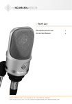
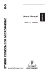
TLM 103 D
Bedienungsanleitung
2
Operating Manual
7
Registrieren Sie bitte Ihr
System auf der Website
www.my-Solution-D.com,
um über Updates informiert
zu werden!
Please register your system
on the website
www.my-Solution-D.com,
to be informed whenever updates
are available!
georg neumann gmbh · ollenhauerstr. 98 · 13403 berlin · germany
fon +49 (0)30 / 41 77 24-0 · fax -50 · [email protected] · www.neumann.com
1.
angeschlossen wird. Das TLM 103 D ist gegen
Überspannung geschützt und verträgt kurzzeitig
bis +55 V.
Einleitung
In dieser Anleitung finden Sie alle wichtigen Informationen für den Betrieb und die Pflege des von
Ihnen erworbenen Mikrophons. Lesen Sie diese
Anleitung bitte sorgfältig und vollständig, bevor
Sie es benutzen. Bewahren Sie die Anleitung bitte
so auf, dass sie für alle momentanen und späteren
Nutzer jederzeit zugänglich ist.
• Reparatur- und Servicearbeiten dürfen nur von
erfahrenem und autorisiertem Fachpersonal
durchgeführt werden. Wenn Sie das Mikrophon
eigenmächtig öffnen oder umbauen, erlischt
die Gewährleistung.
• Verwenden Sie das Mikrophon nur in dem in
den Technischen Daten angegebenen Leistungsbereich.
• Lassen Sie das Mikrophon auf Umgebungstemperatur akklimatisieren, bevor Sie es einschalten.
• Nehmen Sie das Mikrophon nicht in Betrieb,
wenn es beschädigt ist.
• Verlegen Sie Kabel stets so, dass niemand darüber stolpern kann.
• Halten Sie Flüssigkeiten vom Mikrophon und
dessen Anschlüssen fern.
• Verwenden Sie zum Reinigen keine Lösungsmittel oder aggressiven Reinigungsmittel.
• Entsorgen Sie das Mikrophon nach den Bestimmungen Ihres Landes.
Weitergehende Informationen, insbesondere
auch zu den verfügbaren Zubehörteilen und den
Neumann-Servicepartnern, finden Sie auf unserer
Website www.neumann.com. Die Servicepartner
können Sie auch telefonisch unter +49 (0) 30 /
41 77 24 – 0 erfragen.
Auf unserer Website www.neumann.com finden
Sie in der Rubrik Downloads ergänzend folgende
PDF-Dateien:
• Hinweise zur Pflege des Mikrophons
• Bedienungsanleitung DMI-2 (Digitales Mikrophon-Interface)
• Bedienungsanleitung RCS (Remote Control
Software)
• Bedienungsanleitung Connection Kit
• Kurzbeschreibung des Standards AES 42
In der Rubrik Downloads steht auch die aktuelle
Version der Mikrophon- und DMI-Software sowie
der RCS zur Verfügung.
Weitergehende Informationen zur Schnittstelle
digitaler Mikrophone finden Sie bei www.aes.org/
standards unter „AES standards for acoustics, Digital interface for microphones“.
Zum weltweiten Erfahrungsaustausch unter
Neumann-Anwendern bieten wir das Neumann
Online-Forum an, das sich durch die integrierte
Archivfunktion zu einem umfangreichen KnowHow-Pool entwickelt hat.
2.
Sicherheitshinweise
Der bestimmungsgemäße Gebrauch dieses Mikrophons ist die Wandlung akustischer in digitale
elektrische Signale.
Schließen Sie das Mikrophon nur an Mikrophoneingänge und Speisegeräte an, die eine
Phantomspeisung nach AES 42 liefern.
Das Mikrophon wird jedoch nicht beschädigt, falls
es versehentlich kurzzeitig an einen analogen
Mikrophoneingang mit 48 V-Phantomspeisung
D
2
3.
Beschreibung
Das TLM 103 D ist ein Studio-Kondensatormikrophon mit Nieren-Charakteristik und digitalem
Ausgang gemäß dem Standard AES 42. Dieser basiert auf dem in Studiogeräten üblichen Standard
AES 3 (AES/EBU) für digitale Audiosignale, erweitert um die Phantomspeisung für das Mikrophon,
um Fernsteuer- und Synchronisationsdaten sowie
um User-Bits zur Übertragung von Mikrophoninformationen.
Das TLM 103 D ist mit einer Großmembrankapsel
ausgerüstet. Diese hat einen bis ca. 5 kHz ebenen
Frequenzgang, darüber eine breite, fl ache Präsenzanhebung.
Das Mikrophon zeichnet sich aus durch besonders saubere und verfärbungsfreie Klangübertragung bei sehr niedrigem Eigengeräuschpegel
und gleichzeitig höchster Aussteuerbarkeit. Es
verwendet zur Digitalisierung ein von Neumann
entwickeltes und patentiertes A/D-Wandlungsverfahren. Dadurch ist sichergestellt, dass der
gesamte Dynamikumfang des Kapselsignals in
die digitale Ebene überführt wird. Mit der integrierten digitalen Signalverarbeitung bietet das
Mikrophon außerdem Funktionen, die bisher nur
im Mischpult oder zusätzlichen Geräten realisiert
werden konnten. Diese Funktionen werden im Kapitel Technische Daten beschrieben.
Steht zum Anschluss des Mikrophons kein AES 42Eingang (z. B. am Mischpult) zur Verfügung, bietet
Neumann zwei Anschlussmöglichkeiten an: Connection Kits zur reinen Stromversorgung sowie
das zweikanalige Digitale Mikrophon-Interface
(DMI-2) mit der dazugehörigen Steuersoftware
RCS zur Fernsteuerung aller Mikrophoneigenschaften (siehe auch Kapitel Technische Daten).
Die Leistungsaufnahme des Mikrophons führt zu
einer Eigenerwärmung, die mit kleineren Kabellängen und höheren Abtastraten zunimmt.
4.
Für die Verbindung des DMI-2 und des Connection
Kits mit ihrem Audiogerät lesen Sie bitte die entsprechende Bedienungsanleitung.
Eine blaue LED im Mikrophon zeigt bei korrekter
Speisung die Betriebsbereitschaft an. Sie leuchtet beim Einschalten zunächst schwach und nach
kurzer Zeit mit der voreingestellten Helligkeit.
Diese kann bei Verwendung des Digitalen Mikrophon-Interfaces DMI-2 mit der Remote Control
Software in vier Stufen variiert und ausgeschaltet
werden.
Achten Sie beim Anschließen von Kabeln auf die
korrekte Verriegelung der Steckverbinder.
Besprechen Sie das Mikrophon von der Seite aus,
auf der sich das Neumann-Logo befindet.
Inbetriebnahme
Erhöhen Sie an den weiterverarbeitenden Geräten
schrittweise den Lautstärkepegel.
Mikrophon einrichten
Befestigen Sie das Mikrophon auf einem ausreichend stabilen und standfesten Stativ. Verwenden
Sie ggf. eine elastische Aufhängung, um die Übertragung von Körperschallgeräuschen mechanisch
zu unterdrücken. Setzen Sie dafür das Mikrophon
von oben in den Innenkorb ein und schrauben
Sie es mit der Rändelmutter am Innenkorb fest.
Zur Dämpfung von Wind- oder Popgeräuschen
verwenden Sie bei Bedarf einen Wind- oder Popschutz aus unserem Zubehörprogramm.
Lange Kabel und mehrfache Steckverbindungen
führen zu einer Verschlechterung des Jitter-Verhaltens insbesondere bei hohen Abstastraten.
Verwenden Sie daher möglichst durchgehende Kabelverbindungen zwischen Mikrophon und Folgegerät und bei größeren Distanzen ausschließlich
AES/EBU-Kabel (Wellenwiderstand 110 Ohm).
Mikrophon anschließen
Vorsicht: Eine falsche Versorgungsspannung
kann das Mikrophon beschädigen!
Schließen Sie das Mikrophon nur an Mikrophoneingänge und Speisegeräte an, die eine Phantomspeisung nach AES 42 liefern. Siehe auch Kapitel
„Sicherheitshinweise“.
Vorsicht: Sehr hohe Signalpegel können Ihr
Gehör und Ihre Laut sprecher schädigen!
Reduzieren Sie an den angeschlossenen Wiedergabegeräten die Lautstärke, bevor Sie das Mikrophon anschließen, auch wegen der Gefahr der
akustischen Rückkopplung.
Verbinden Sie das Mikrophon über ein XLR-Kabel
mit dem AES 42-Mikrophoneingang Ihres Digitalen Mikrophon-Interface DMI-2, des Neumann
Connection Kits oder eines anderweitigen Audiogerätes nach AES 42.
Achten Sie darauf, dass das Mikrophon und alle
Geräte der digitalen Signalkette synchronisiert
sind. Wird das Digitale Mikrophon-Interface von
Neumann verwendet, sollten die angeschlossenen
Mikrophone immer im Synchronmode betrieben
werden, unabhängig davon, ob in der nachfolgenden Signalkette Sample Rate Converter im
Einsatz sind. Auf diese Weise wird im DMI eine
sehr effektive Jitterunterdrückung wirksam (ab
Hardwarerevision 3). Auch ist die Ausgabe zweier
Mikrophonsignale in einem AES 3-Stereosignal
nur möglich, wenn die Mikrophone untereinander
synchronisiert sind.
Tontest
Sprechen Sie das Mikrophon einfach nur an. Anpusten oder „Anploppen“ führt zu gefährlichen
Schalldruckpegeln.
Parameter, die über die AES 42-Schnittstelle
ferngesteuert werden können
Low Cut: Der Low Cut bietet gemäß AES42-Standard die vier Einstellungen: off, 40 Hz, 80 Hz und
160 Hz.
3
D
Vordämpfung: Die Vordämpfung wird durch
Reduktion der Kapselspannung realisiert. Bei
Aktivierung wird der Dynamikbereich um den
entsprechenden Wert zu höheren Schalldrücken
verschoben.
Gain: Die Verstärkung erfolgt ausschließlich auf
der digitalen Ebene und führt damit nicht zu der
aus der analogen Welt bekannten Rauschaddition
und zu möglichen Klangbeeinflussungen.
Peak-Limiter: Der sehr schnelle Peak-Limiter hat
eine einstellbare Ansprechschwelle und verhindert Übersteuerungen bzw. Clippen des Audiosignals im Signalweg.
Kompressor/Limiter: Weiterhin ist ein vollständig
parametrisierbarer Kompressor/Limiter implementiert. Dieser kann breitbandig oder als Hochtonkompressor/Limiter (De-Esser) in einem von
drei wählbaren Frequenzbereichen arbeiten. Alle
wichtigen Parameter sind einstellbar.
Außerdem lassen sich die Abtastrate, der Synchronisationsmodus, Testsignale, Mute, die Polarität
des Ausgangssignals und die LED fernsteuern.
Die Software im Mikrophon kann über das Neumann DMI-2 aktualisiert werden, so dass zukünftige Erweiterungen der Software auch bestehenden Kunden zur Verfügung stehen werden. Zu
Details des Updatevorganges lesen Sie bitte die
RCS-Anleitung.
Störschallunterdrückung
Der Übertragungsbereich des TLM 103 D reicht
bis unter 20 Hz. Entsprechend empfindlich ist
das Mikrophon natürlich auch für tieffrequente
Störungen wie Körperschall oder Wind- und Popgeräusche. Daher empfiehlt sich ggf. die Verwendung einer elastischen Aufhängung, eines Windschutzes und/oder eines Popschirmes.
5.
Außerbetriebnahme und Aufbewahrung
Verringern Sie vor der Außerbetriebnahme und
dem Abziehen von Kabeln den Lautstärkepegel
Ihres weiterverarbeitenden Gerätes.
Ziehen Sie beim Lösen von Kabeln stets nur an
den Steckverbindern und nicht am Kabel.
Mikrophone, die längere Zeit nicht verwendet
werden, sollten bei normalem Umgebungsklima
staubgeschützt aufbewahrt werden. Verwenden
Sie hierfür einen nicht fusselnden, luftdurchlässigen Staubschutzbeutel oder die Originalverpackung des Mikrophons.
D
4
6.
Technische Daten
1)
Zulässige klimatische Verhältnisse:
Betriebstemperaturbereich.............. 0 °C … +40 °C
Lagerungstemperaturbereich ...... –20 °C … +70 °C
Feuchtebereich ......................0 % … 99 % rel. hum.
bei +20 °C
0 % … 95 % rel. hum.
bei +60 °C
Akust. Arbeitsweise ................... Druckgradientenempfänger
Richtcharakteristik .........................................Niere
Übertragungsbereich ......................20 Hz...20 kHz
Feldübertragungsfaktor2) ........................–39 dBFS
Ersatzgeräuschpegel,
CCIR4) ............................................................ 17,5 dB
Ersatzgeräuschpegel,
A-bewertet4) .................................................. 7 dB-A
Geräuschpegelabstand3),
CCIR4) ........................................................... 76,5 dB
Geräuschpegelabstand3),
A-bewertet4) ................................................... 87 dB
Grenzschalldruckpegel
bei 0 dBFS ............................................. 134 dBSPL
Dynamikumfang4) ......................................... 127 dB
A/D-Wandlung ........................Neumann-Verfahren
(patentiert), 28 Bit
interne Wortbreite
Digitale Signalverarbeitung ......Fixpoint, variable
interne Wortbreite,
28...60 Bit
Ausgangsdatenformat ...........24 Bit nach AES/EBU
(AES 3)
Abtastraten .......44,1/48/88,2/96/176,4/192 kHz
Latenzzeit:
44,1/48 kHz .......................................... 52 Samples
88,2/96 kHz.......................................... 61 Samples
176,4/192 kHz.........................121 Samples (AES 3)
Synchronisation:
freilaufend (nicht synchronisiert),
Frequenz-Grundgenauigkeit.................... ± 25 ppm
Bei 0 dB Vordämpfung und 0 dB Gain.
1)
Alle Werte für nicht-kondensierende Feuchtigkeit.
2)
bei 1 kHz und 94 dB SPL
3)
bezogen auf 94 dB SPL
4)
nach IEC 60268-1;
CCIR-Bewertung nach CCIR 468-3, Quasi-Spitzenwert;
A-Bewertung nach IEC 61672-1, Effektivwert
synchroner Betrieb,
Ziehbereich .................................... min. ± 100 ppm
Stromversorgung
(Phantomspeisung gemäß AES 42)
Arbeitsspannungsbereich ................... +7...+10,5 V
Stromaufnahme ..................................max. 150 mA
Steckverbinder ............................................ XLR 3 M
Abmessungen ..................................Ø 60 x 132 mm
Gewicht ...........................................................460 g
Fernsteuerbare Funktionen
7.
Zubehör* (Fotos im Anhang)
Connection Kits & Interface
Connection Kit AES/EBU............ Best.-Nr. 008584
Connection Kit S/PDIF ............... Best.-Nr. 008585
Interface DMI-2 (EU) .................. Best.-Nr. 008561
Interface DMI-2 (UK) .................. Best.-Nr. 008587
Interface DMI-2 (US) .................. Best.-Nr. 008588
Elastische Aufhängungen
EA 1 ..........................ni ................ Best.-Nr. 008449
EA 1 mt .....................sw ............... Best.-Nr. 008450
Vordämpfung ..............................0/–6/–12/–18 dB
Hochpassfilter ...........................Off/40/80/160 Hz
Digitale Signalverstärkung ...............0...10...63 dB
in 1 dB-Schritten, knackfrei
Testsignal ............................Off, 1 kHz (–48 dBFS),
rosa Rauschen (–35 dBFS),
weißes Rauschen (–43 dBFS)
Mikrophonneigevorrichtung
MNV 87 ....................ni ................ Best.-Nr. 006804
MNV 87 mt ...............sw ............... Best.-Nr. 006806
Kompressor/Limiter ..................................... On/Off
Untere Grenzfrequenz
des Arbeitsbereichs ........... flat/1 kHz/2 kHz/4 kHz
Max. Dämpfung (gain reduction):
flat mode ....................................................... > 63 dB
1 kHz/2 kHz/4 kHz ........................................ > 20 dB
Ratio ...............................................1,2:1/1,5:1/2:1/
3:1/4:1/6:1/8:1/>100:1
Threshold ........................–63 dBFS..–10...0 dBFS,
in 1 dB Stufen
Attack time ............. 0/0,1/0,3/1/3/10/30/100 ms
Release time ..................0,05/0,1/0,2/0,5/1/2/5 s
Tisch- und Fußbodenständer
MF 3 .........................sw ............... Best.-Nr. 007321
MF 4 .........................sw ............... Best.-Nr. 007337
MF 5 .........................gr ................ Best.-Nr. 008489
(bezogen auf eine Pegeländerung von ca. 10 dB )
Peak-Limiter.................................................. On/Off
Threshold ........................................Off: 0 dBFS fest
On: –15 dBFS...0 dBFS,
in 1 dB-Stufen
Attack time ...................................–160 µs (negativ)
Release time ............................. ca. 50 ms...150 ms
(signalabhängig)
Mute............................................................... On/Off
Phase (Polarität) .........................................0, 180°
Anzeige ................................................... LED (blau),
Helligkeit einstellbar
Abtastraten ....................................... 44,1/48/8,.2/
96/176,4/192 kHz
Stativgelenke, weitere mechanische Adapter
DS 120 .....................sw ............... Best.-Nr. 007343
SG 1 ..........................sw ............... Best.-Nr. 008445
Schaumstoff windschutz
WS 87 .......................sw ............... Best.-Nr. 006753
Popschutz
PS 15 .......................sw ............... Best.-Nr. 008472
PS 20 a ...................sw ............... Best.-Nr. 008488
Anschlusskabel
IC 3 mt .....................sw ............... Best.-Nr. 006543
IC 4 ..........................ni ................ Best.-Nr. 006547
IC 4 mt .....................sw ............... Best.-Nr. 006557
Bedeutung der Farbcodierungen:
ni = nickel, sw = schwarz, gr = grau
* Ausführliche Beschreibungen und weitere Artikel finden Sie
in unserem Zubehörkatalog oder unter www.neumann.com
(Werkseinstellung je nach Variante)
Werkseinstellungen sind fett gekennzeichnet. Diese können
bei Verwendung des DMI mit der Remote Control Software
jederzeit geändert werden.
5
D
8.
Lieferumfang
1.
Mikrophon
Starter-Set
Mikrophon TLM 103 D (mt)
Mikrophon TLM 103 D
Stativgelenk SG 1
Elastische Aufhängung EA 1
Bedienungsanleitung
Connection Kit
Holzetui
Bedienungsanleitung
9.
▶ Mögliche Ursachen
▶ Abhilfe
Keine
Funktion /
Keine Signalübertragung
Speisespannung fehlt
Überprüfen Sie das Speisegerät und ggf. die
zugehörigen Software-Einstellungen
(RCS -> System -> MicPWR).
Das Mikrophon ist nicht mit
einem AES 42-Eingang verbunden
Verwenden Sie einen AES 42–Eingang.
Das Mikrophon ist nicht mit dem
richtigen Kanal verbunden
Überprüfen Sie den Signalweg.
The following related files are available in PDF
format in the Downloads section of our website
www.neumann.com:
• Some Remarks on Microphone Maintenance
• DMI-2 Digital Microphone Interface Operating
Manual
• RCS Remote Control Software Operating Manual
• Connection Kit Operating Manual
• Short description of the AES 42 standard
Additional information concerning the digital
microphone interface can be found in standard
AES 42 on the website: www.aes.org/standards
“AES standards for acoustics, Digital interface for
microphones”.
Aktivieren Sie ggf. den entsprechenden Eingang auf
dem zugeordneten Kanalzug des Mischpults.
Deaktivieren Sie in der AES 42-Fernsteuerung Mute.
Zu hohe Schalldrücke im
aufzunehmenden Tonsignal
Vergrößern Sie den Aufnahmeabstand oder aktivieren
Sie die Vordämpfung in Ihrer AES 42-Fernsteuerung.
Übersteuerung durch tieffrequente Störgeräusche
(Trittschall, Wind)
Benutzen Sie einen geeigneten Windschutz (Zubehör).
Aktivieren Sie die Vordämpfung in Ihrer AES 42-Fernsteuerung.
Übersteuerung durch Explosivlaute
Benutzen Sie einen geeigneten Popschutz (Zubehör).
Aktivieren Sie die Vordämpfung in Ihrer AES 42-Fernsteuerung.
Ton klingt
dumpf, räumlich
Richtcharakteristik nicht
beachtet
Prüfen Sie, ob das Mikrophon von der richtigen Seite
angesprochen wird.
Orientieren Sie sich am Neumann-Logo.
Keine
Synchronisation
Asynchroner Betrieb ist
eingestellt
Wählen Sie den Synchronmode (Mode 2, RCS).
The microphone has the intended purpose of
converting acoustic signals into digital electrical
signals.
Sample Rate von Mikrophon und
Folgegerät stimmen nicht überein
Synchronisieren Sie den digitalen Eingang mit der
Quelle.
Connect the microphone only to microphone
inputs and to equipment which supplies phantom power in accordance with AES 42.
Verwenden Sie einen Sample-Rate-Converter.
Externer Word Clock wird
erkannt, aber liegt außerhalb der
Spezifikation
6
Additional information, in particular concerning available accessories and Neumann service
partners, can be found on our website: www.neumann.com. Information about service partners
can also be obtained by telephone: +49 (0) 30 /
41 77 24 - 0.
Der Kanal ist gemutet
Ton verzerrt /
schlechte
Signalqualität
D
This manual contains essential information for the
operation and care of the microphone you have
purchased. Please read the instructions carefully
and completely before using the product. Please
keep this manual where it will be accessible at all
times to all current and future users.
Fehlercheckliste
Fehler
Überprüfen Sie den externen Wordclock auf Genauigkeit und Signalqualität (Jitter? Sehr lange Kabel?).
Alternative Abhilfe: Verwenden Sie den internen
DMI-Wordclock als Master Word Clock für die gesamte
Signalkette.
• Repairs and servicing are to be carried out only
by experienced, authorized service personnel.
Unauthorized opening or modification of the
microphone shall void the warranty.
• Use the microphone only under the conditions
described in the Technical Data.
• Allow the microphone to adapt to the ambient
temperature before switching it on.
• Do not operate the microphone in a damaged
condition.
• Always run cables in such a way that there is no
risk of tripping over them.
• Ensure that liquids are kept at a safe distance
from the microphone and its connections.
• Do not use solvents or aggressive cleansers for
cleaning purposes.
• Dispose of the microphone in accordance with
the regulations applicable to the respective
country.
Introduction
Our Neumann online forum enables Neumann
users worldwide to share their experiences.
Through its integrated archive function, the forum
has developed into an extensive knowledge pool.
2.
Safety instructions
But the microphone will not be damaged if it is
accidentally connected to an analog microphone
input with a phantom power of 48 V for a short
period. The TLM 103 D has overvoltage protection
and can handle a voltage of up to +55 V for a short
period.
3.
Description
The TLM 103 D is a condenser studio microphone
with a cardioid directional characteristic and a
digital output that complies with the standard
AES 42. Based upon the usual AES 3 (AES/EBU)
standard for digital audio signals in studio equipment, this standard has been extended to include
phantom power for the microphone, remote control and synchronization data, and user bits for
the transmission of microphone information.
The microphone houses a large diaphragm capsule. It has a linear frequency response up to approximately 5 kHz, above which there is a broad,
flat presence boost.
The microphone features exceptionally clean
sound transmission which is free of coloration,
with very low self-noise and an extensive dynamic
range. Digitization is performed by an A/D conversion process developed and patented by Neumann. This ensures that the full dynamic range
of the capsule signal is transferred to the digital
realm. The integrated digital signal processing
also permits functions to be provided which were
previously available only via the mixing console
or additional studio equipment. These functions
are described in the “Technical data” section.
If there is no microphone input according to
AES 42 standard available Neumann provides
Connection Kits for the simple supply of power, as
7
EN
well as the two-channel Digital Microphone Interface (DMI-2) with the accompanying RCS control
software for remote controlling all microphone
characteristics (see also the “Technical data” section).
The consumption of power results in slight warming of the microphone, which increases with
shorter cable lengths and higher sampling rates.
4.
Setup
Mounting the microphone
Attach the microphone to a stable, sturdy stand.
Use an elastic suspension, if necessary, for the
mechanical suppression of structure-borne noise.
For this purpose set the microphone into the inner
cage from above, and secure it to the inner cage
with the threaded nut. If required, use a windscreen or popscreen from our range of accessories in order to suppress wind or pop noise.
Connecting the microphone
Caution: An incorrect supply voltage can damage the microphone!
Connect the microphone to microphone inputs
and to equipment which supplies phantom power in accordance with AES 42. See also chapter
“Safety Instructions”.
Caution: Very high signal levels can damage
loudspeakers and your hearing!
Reduce the volume of connected playback equipment before connecting the microphone. This is
also advisable in order to avoid acoustic feedback.
Connect the microphone by means of an XLR cable
to the AES 42 microphone input of the DMI-2 Digital Microphone Interface, to the Neumann connection kit or to other audio equipment along to
AES 42 standard.
Concerning the connection of DMI-2 and Connection Kits with your audio device please consult
the respective operating manuals.
With a correct power supply, a blue LED on the microphone indicates that the microphone is ready
to operate. When the microphone is switched
on, the LED at first glows dimly, and after a short
time shines with the preset brightness. When the
DMI-2 Digital Microphone Interface is used, the
LED can be set to four different brightness levels
EN
8
and switched off by means of the Remote Control
Software.
When connecting the cables, ensure that the connectors are locked correctly.
Address the microphone from the side on which
the Neumann logo is located.
Gradually increase the volume of the connected
equipment.
Long cables and multiple connectors lead to deterioration in jitter behavior, particularly in the case
of high sampling rates. Therefore, to the greatest
extent possible, use continuous cable between
the microphone and subsequent equipment, and
for longer distances use AES/EBU cable exclusively (with an impedance level of 110 ohms).
Ensure that the microphone and all equipment in
the digital signal chain are synchronized. If the
Neumann Digital Microphone Interface is used,
the connected microphones should always be
operated in synchronous mode, whether or not
sample rate converters are used in the subsequent signal chain. This will ensure very effective
jitter suppression in the DMI (as of hardware version 3). The output of two microphone signals in
an AES 3 stereo signal is also possible only if the
microphones are synchronized with one another.
Sound test
Simply speak into the microphone. Do not blow
into the microphone or subject it to pop noise,
since this can easily result in hazardous sound
pressure levels.
Parameters which can be remote controlled
via the AES 42 interface
Low Cut: Acccording to AES42 there are four settings for the low cut: off, 40 Hz, 80 Hz and 160 Hz.
Pre-attenuation: Pre-attenuation is achieved by
reducing the capsule voltage. If pre-attenuation is
activated, the dynamic range is shifted by the corresponding value to higher sound pressure levels.
Gain: Gain is carried out exclusively in the digital
domain, thus avoiding the additional noise and
possible effects on the sound which can occur in
analog processing.
Peak limiter: The very fast peak limiter has an adjustable threshold, and prevents overloading or
clipping of the audio signal in the signal path.
Compressor/Limiter: A compressor/limiter with
completely adjustable parameters is provided.
It can function in broad band mode, or as a highfrequency compressor/limiter (de-esser) in one of
three selectable frequency ranges. All important
parameters are adjustable.
In addition, the sampling rate, the synchronization mode, test signals, mute, the polarity of the
output signal and the LED can be controlled remotely.
The software in the microphone can be updated
via the Neumann DMI-2. Therefore future software enhancements will also be available to existing customers. Please refer to the RCS manual
for details concerning the update process.
Suppressing noise interference
The frequency response of the TLM 103 D extends
below 20 Hz. The microphone is of course correspondingly sensitive to low-frequency interference such as structure-borne noise and wind or
pop noise. Depending upon the situation, the use
of an elastic suspension, a windscreen and/or a
popscreen is therefore recommended.
5.
Shutdown and Storage
Before switching off the microphone or disconnecting the cables, reduce the volume of connected equipment.
When disconnecting a cable, always pull only on
the connector and not on the cable itself.
Microphones which are unused for prolonged
periods should be stored under normal ambient
atmospheric conditions, and should be protected
from dust. For this purpose, use a lint-free, airpermeable dust cover or the original packaging of
the microphone.
6.
Technical data
Permissible atmospheric conditions1)
Operating temperature range.......... 0 °C to +40 °C
Storage temperature range ...........–20 °C to +70 °C
Humidity range .....................0 % to 99 % at +20 °C
0 % … 95 % at +60 °C
Acoustical op. principle .............Pressure gradient
transducer
Directional
pattern........................................................ Cardioid
Frequency range ............................ 20 Hz to 20 kHz
Sensitivity2) ..............................................–39 dBFS
Equivalent noise level,
CCIR4) ............................................................ 17.5 dB
Equivalent noise level,
A-weighted4) .................................................. 7 dB-A
Signal-to-noise ratio3),
CCIR4) ........................................................... 76.5 dB
Signal-to-noise ratio3),
A-weighted4) ................................................... 87 dB
Maximum SPL
at 0 dBFS3) ............................................. 134 dBSPL
Dynamic range
including capsule4) ....................................... 127 dB
A/D conversion ...........................Neumann process
(patented), 28-bit
internal word length
Digital signal processing ..... Fixed-point, variable
internal word length
28 bits to 60 bits
Sampling rates .................................44.1/48/88.2/
96/176.4/192 kHz
Output data format ............................ 24 bits as per
AES/EBU (AES 3)
Sampling rates .................................44.1/48/88.2/
96/176.4/192 kHz
Latency:
44.1/48 kHz ...........................................52 samples
88.2/96 kHz ...........................................61 samples
176.4/192 kHz...................................... 121 samples
At 0 dB pre-attenuation and 0 dB gain.
1)
All values are for non-condensing moisture.
2)
at 1 kHz, and 94 db SPL
3)
re 94 dB SPL
4)
according to IEC 60268-1;
CCIR-weighting acccording to CCIR 468-3, quasi peak;
A-weighting according to IEC 61672-1, RMS
9
EN
Synchronization
Free-running (non-synchronous operation),
frequency stability ................................... ± 25 ppm
Synchronous operation,
pulling range .................................. min. ± 100 ppm
Power supply
(phantom power complying with AES 42)
Supply voltage range .......................+7 V to +10.5 V
Current consumption .........................max. 150 mA
Connector..................................................... XLR 3 M
Dimensions ......................................Ø 60 x 132 mm
Weight .............................................................460 g
Remote controlled functions
Pre-attenuation ..........................0/–6/–12/–18 dB
High-pass filter ..........................Off/40/80/160 Hz
Digital gain.........................................0...10...63 dB
in steps of 1 dB, clickless
Test signals ..........................Off, 1 kHz (–48 dBFS),
Pink noise (–35 dBFS),
White noise (–43 dBFS)
Compressor/Limiter ..................................... On/Off
Lower cut-off frequency
of the working range ..........Flat/1 kHz/2 kHz/4 kHz
Max. gain reduction:
Flat mode ...................................................... > 63 dB
1 kHz/2 kHz/4 kHz ........................................ > 20 dB
Compression ratio ......................... 1.2:1/1.5:1/2:1/
3:1/4:1/6:1/8:1/>100:1
Threshold .......................–63 dBFS...–10...0 dBFS,
in steps of 1 dB
Attack time ............. 0/0.1/0.3/1/3/10/30/100 ms
Release time ..................0.05/0.1/0.2/0.5/1/2/5 s
(for a level change of approx. 10 dB )
Peak limiter ................................................... On/Off
Threshold ......................................Off: 0 dBFS fixed
On: –15 dBFS to 0 dBFS,
in steps of 1 dB
Attack time .................................–160 µs (negative)
Release time .................. Approx. 50 ms to 150 ms
(signal-dependent)
7.
Accessories* (see photos in appendix)
Connection Kits & Interface
Connection Kit AES/EBU..............Cat. No. 008584
Connection Kit S/PDIF .................Cat. No. 008585
Interface, DMI-2 (230 V, EU) .......Cat. No. 008561
Interface, DMI-2 (230 V, UK) .......Cat. No. 008587
Interface, DMI-2 (170 V, US) .......Cat. No. 008588
Auditorium Hanger
MNV 87 ....................ni ..................Cat. No. 006804
MNV 87 mt ...............blk ................Cat. No. 006806
Stand Mounts, Misc. Mechanical Adapters
DS 120 .....................blk ................Cat. No. 007343
SG 1 ..........................blk ................Cat. No. 008445
Table and Floor Stands
MF 3..........................blk ................Cat. No. 007321
MF 4 .........................blk ................Cat. No. 007337
MF 5 .........................gry ................Cat. No. 008489
10
Microphone
Starter Set
TLM 103 D (mt) microphone
TLM 103 D microphone
SG 1 stand mount
EA 1 elastic suspension
Operating manual
Connection Kit
Wooden case
Operating manual
9.
Troubleshooting
Problem
▶ Possible causes
▶ Solution
Microphone not
operating /
No signal
transmission
Supply voltage not activated
Check the power supply device and if necessary
the associated software settings (RCS -> System ->
MicPWR).
The microphone is not connected
to an AES 42 input
Use an AES 42 input.
The microphone is not connected
to the right channel
Check the signal path.
The channel is muted
Deactivate the mute in the AES 42 remote control.
Excessive sound pressure of the
signal to be recorded
Take a more distant microphone position or activate
the pre-attenuation in the AES 42 remote control.
Overload due to low-frequency
interference (e.g. impact sound
or wind)
Use an appropriate windscreen (accessory). Activate
the pre-attenuation in the AES 42 remote control.
Overloading due to Plosives
Use an appropriate popscreen (accessory). Activate
the pre-attenuation in the AES 42 remote control.
Sound is muffled
and reverberant
Incorrect directional
characteristics
Check to ensure that the microphone is being
addressed from the correct side, as designated by the
Neumann logo
No
synchronization
Operation is set to asynchronous
mode
Activate the synchronization of the AES 42 input
(mode 2, RCS).
The sample rates of the microphone and the subsequent equipment do not correspond with one
another
Synchronize the digital input with the source.
An external word clock is
detected but does not conform to
specifications
Check the external word clock for precision and signal
quality (e.g. check for jitter or very long cables).
Foam Windscreens
WS 87 .......................blk ................Cat. No. 006753
Popscreen
PS 15 .......................blk ................Cat. No. 008472
PS 20 a ...................blk ................Cat. No. 008488
Connecting Cables
IC 3 mt ....................blk ................Cat. No. 006543
IC 4 ...........................ni ..................Cat. No. 006547
IC 4 mt .....................blk ................Cat. No. 006557
Meaning of color codes:
ni = nickel, blk = black, gry = grey
(Factory setting depending on version supplied.)
EN
Scope of delivery
Elastic Suspensions
EA 1 ..........................ni ..................Cat. No. 008449
EA 1 mt .....................blk ................Cat. No. 008450
Mute............................................................... On/Off
Phase (polarity) ......................................... 0°, 180°
Signal light ............................................. LED (blue),
brightness adjustable
Sampling rates .................................44.1/48/88.2/
96/176.4/192 kHz
Factory settings are indicated in bold. If the DMI is used, they
can be changed at any time via the Remote Control Software.
8.
*
Detailed descriptions and additional articles can be found
in our accessories catalog or at: www.neumann.com
Distorted
sound /
bad signal
quality
If necessary, activate the appropriate input on the
corresponding channel of the mixing console.
Use a sample rate converter.
Alternative solution: Use the internal DMI word clock
as the master word clock for the entire signal chain.
11
EN
12
Connection Kit AES/EBU
Connection Kit S/PDIF
Interface DMI-2
IC 3 mt
IC 4 (mt)
EA 1 (mt)
DS 120
SG 1
MNV 87
MF 3
MF 4
MF 5
PS 15
PS 20 a
WS 87
13
10. Frequenz- und Polardiagramme
10. Frequency responses and polar patterns
gemessen im freien Schallfeld nach IEC 60268-4
measured in free-fi eld conditions (IEC 60268-4)
14
15
®
Konformitätserklärung
Declaration of Conformity
Die Georg Neumann GmbH erklärt, dass dieses Gerät
die anwendbaren CE-Normen und -Vorschriften erfüllt.
Neumann ist in zahlreichen Ländern eine eingetragene
Marke der Georg Neumann GmbH.
Georg Neumann GmbH hereby declares that this device
conforms to the applicable CE standards and regulations.
Neumann is a registered trademark of the
Georg Neumann GmbH in certain countries.
®
Irrtümer und technische Änderungen vorbehalten • Errors excepted, subject to changes
Printed in Germany • Publ. 03/08 525961