1
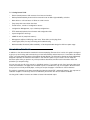
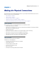
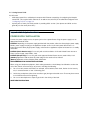
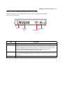
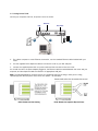
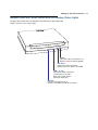
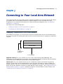
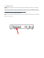
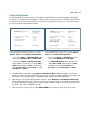
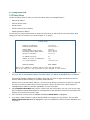
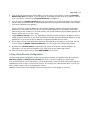
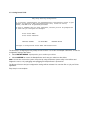
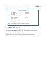
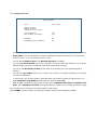
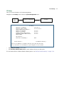
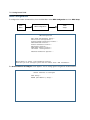
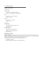
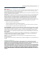
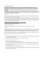
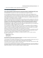
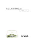
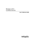
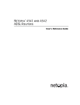
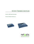
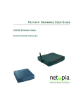
®
Netopia 3366C-ENT
ADSL Router with V.92 Backup
Getting Started Guide
Copyright
©2004 Netopia, Inc., v.032504
Netopia and the Netopia logo are registered trademarks belonging to Netopia, Inc.,
registered U.S. Patent and Trademark Office. Broadband Without Boundaries is a trademark
belonging to Netopia, Inc. All other trademarks are the property of their respective owners.
All rights reserved.
Netopia, Inc.
6001 Shellmound Street, 4th Floor
Emeryville, CA 94608
U.S.A.
Part Number
Netopia part number 6161181-00-01
Contents
Contents
3
Chapter 1 — Introduction..........................................................1-1
Overview ....................................................................... 1-1
Features and Capabilities ............................................... 1-1
How to Use this Guide.................................................... 1-2
Chapter 2 — Making the Physical Connections..........................2-1
Find a Location .............................................................. 2-1
What You Need .............................................................. 2-1
Important Safety Instructions ......................................... 2-2
POWER SUPPLY INSTALLATION .............................. 2-2
Identify the Connectors and Attach the Cables ................. 2-3
Netopia 3366C-ENT ADSL Router with V.92 Backup Status
Lights ........................................................................... 2-5
Chapter 3 — Connecting to Your Local Area Network .................3-1
Readying Computers on Your Local Network..................... 3-1
Connecting to an Ethernet Network ................................. 3-2
Chapter 4 — Configuring TCP/IP...............................................4-1
Configuring TCP/IP on Windows-based Computers............ 4-1
Microsoft Windows......................................................... 4-1
Configuring TCP/IP on Macintosh Computers ................... 4-3
Macintosh MacOS 8 or higher or Mac OS X...................... 4-3
Chapter 5 — Console-Based Management .................................5-1
Connecting through a Telnet Session............................... 5-2
Configuring Telnet software ................................... 5-2
Connecting a console cable to your router ....................... 5-3
Navigating through the Console Screens.......................... 5-4
Chapter 6 — Easy Setup ...........................................................6-1
Easy Setup Console Screens .......................................... 6-1
Accessing the Easy Setup Console screens ........... 6-1
Quick Easy Setup Connection Path.................................. 6-2
1. ADSL Line Configuration ................................... 6-4
2. Easy Setup Profile ............................................ 6-5
G
4
Getting Started Guide
3. IP Easy Setup .................................................. 6-6
4. Easy Setup Security Configuration ..................... 6-7
Chapter 7 — Line Backup .........................................................7-1
Configuring Backup ........................................................ 7-1
Connection Profiles ........................................................ 7-2
IP Setup .............................................................. 7-7
WAN Configuration ......................................................... 7-8
Backup Configuration screen............................... 7-10
Using Scheduled Connections with Backup .................... 7-12
Backup Default Gateway............................................... 7-14
Chapter 8 — Technical Specifications and Safety Information.....8-1
Description.................................................................... 8-1
Power requirements ............................................. 8-1
Environment ........................................................ 8-1
Software and protocols......................................... 8-1
Agency approvals........................................................... 8-2
Regulatory notices ............................................... 8-2
Manufacturer’s Declaration of Conformance .................... 8-3
Important Safety Instructions ......................................... 8-4
FCC Part 68 Information................................................. 8-5
Electrical Safety Advisory ............................................... 8-6
Introduction 1-1
Chapter 1
Introduction
Overview
The Netopia 3366C-ENT ADSL Router with V.92 Backup is a full-featured ADSL router for connecting diverse
local area networks (LANs) to the Internet and other remote networks. The Netopia 3366C-ENT ADSL Router
with V.92 Backup connects easily to your DSL line to provide your whole network with a high-speed connection
to the outside world. In addition, the V.92 modem backup provides high-availability by automatically switching to
a dial-up mode in the event of a DSL line failure.
This section covers the following topics:
•
“Features and Capabilities” on page 1-1
•
“How to Use this Guide” on page 1-2
Features and Capabilities
The Netopia 3366C-ENT ADSL Router with V.92 Backup provides the following features:
•
LAN interface: four port 10/100BaseTX RJ-45 Ethernet switch with Auto-crossover support.
•
Point-to-Point Protocol (PAP/CHAP authentication)
•
PPP over Ethernet Gateway
•
PPP over Ethernet pass-through
•
Transparent bridging option
•
Support for IP routing for Internet connectivity
•
Numbered or unnumbered WAN interface
•
Support for Ethernet LANs with up to eight Ethernet IP subnets
•
NAT/NAPT, Multi-NAT, and DHCP (client, server, and relay) for security and convenience
•
DNS proxy
•
IP Multicast Forwarding, IGMP V1, V2
•
RIP1 and RIP2, static routes
•
IP QoS: TOS bit prioritization
•
VPN Pass-through for PPTP and IPSec
•
Built-in VPN gateway features offer support for up to 15 PPTP or IPSec VPN tunnels
•
IPSec implementation supports DES or 3DES encryption, MD5 or SHA1 encapsulation, and manual or IKE
keying
1-2 Getting Started Guide
•
Built-in firewall protects LAN resources from Internet intruders
•
Backup Default Gateway feature with an external router enables high-availability solutions
•
Menu-driven or CLI interfaces via Telnet or serial Console
•
Easy Setup with menu-driven interface
•
Tiered Access, 2 levels of configuration access
•
Configuration Management, up to 3 backup configurations
•
TFTP download/upload of new firmware and configuration files
•
System diagnostics and logs
•
SNMP V1 and V2 (read/write access)
•
Management utilities: ICMP ping, trace route, Telnet client, and Syslog client
•
Status lights (LEDs) for easy monitoring and troubleshooting
•
Wall-mountable, Bookshelf (Side-stackable), or Desktop-stackable design for efficient space usage
How to Use this Guide
In addition to the documentation contained in the accompanying Firmware User’s Guide, this guide is designed
to get you up and running and connected to your local area network and the Internet. It is intended to be viewed
on-line, using the powerful features of the Adobe Acrobat Reader. The information display has been deliberately
designed to present the maximum information in the minimum space on your screen. You can keep this
document open while you perform any of the procedures described, and find useful information about the
procedure you are performing.
You can also print out all of the manual, or individual sections, if you prefer to work from hard copy rather than
on-line documentation. The pages are formatted to print on standard 8 1/2 by 11 inch paper. We recommend
that you print on 3-hole punched paper, so that you can put the pages in a binder for future reference.
This guide is organized into chapters describing the Netopia 3366C-ENT’s advanced features. You may want to
read each chapter’s introductory section to familiarize yourself with the various features available.
Use the guide’s table of contents and index to locate informational topics.
Making the Physical Connections 2-1
Chapter 2
Making the Physical Connections
This section tells you how to make the physical connections to your Netopia 3366C-ENT ADSL Router with V.92
Backup. This section covers the following topics:
•
“Find a Location” on page 2-1
•
“What You Need” on page 2-1
•
“Important Safety Instructions” on page 2-2
•
“Identify the Connectors and Attach the Cables” on page 2-3
•
“Netopia 3366C-ENT ADSL Router with V.92 Backup Status Lights” on page 2-5
Find a Location
When choosing a location for the Netopia ADSL Router with V.92 Backup, consider:
•
Available space and ease of installation
•
Physical layout of the building and how to best use the physical space available for connecting your Netopia
ADSL Router with V.92 Backup to the LAN
•
Available wiring and jacks
•
Distance from the point of installation to the next device (length of cable or wall wiring)
•
Ease of access to the front of the unit for configuration and monitoring
•
Ease of access to the back of the unit for checking and changing cables
•
Cable length and network size limitations when expanding networks
What You Need
Locate all items that you need for the installation.
Included in your router package are:
•
The Netopia 3366C-ENT ADSL Router with V.92 Backup
•
A power adapter and cord
•
One yellow Category 5 Ethernet cable
•
One lavender RJ-11 telephone cable
•
A DB-9 console cable
•
The Netopia CD containing software and documentation
2-2 Getting Started Guide
You will need:
•
A Windows–based PC or a Macintosh computer with Ethernet connectivity for configuring the Netopia
3366C-ENT. This may be built-in Ethernet or an add-on card, with TCP/IP installed and configured. See
“Configuring TCP/IP” on page 4-1.
•
A phone jack to which your ADSL provider is providing ADSL service. (Your phones and ADSL service
generally use the same phone line.)
Important Safety Instructions
POWER SUPPLY INSTALLATION
Connect the power supply cord to the power jack on the Cayman Router. Plug the power supply into an
appropriate electrical outlet.
CAUTION: Depending on the power supply provided with the product, either the direct plug-in power supply
blades, power supply cord plug or the appliance coupler serves as the main power disconnect. It is
important that the direct plug-in power supply, socket-outlet or appliance coupler be located so it is readily
accessible.
CAUTION (North America Only): For use only with a CSA Certified or UL Listed Limited Power Source or
Class 2 power supply, rated 12Vdc, 1.0A.
CAUTION (Europe Only): For use only with a GS approved Limited Power Source, rated 12Vdc, 1.0A.
(Sweden) Apparaten skall anslutas till jordat uttag när den ansluts till ett nätverk
(Norway) Apparatet må kun tilkoples jordet stikkontakt.
TELECOMMUNICATION INSTALLATION CAUTIONS
When using your telephone equipment, basic safety precautions should always be followed to reduce the
risk of fire, electric shock and injury to persons, including the following:
1.
Do not use this product near water, for example, near a bathtub, wash bowl, kitchen sink or laundry
tub, in a wet basement or near a swimming pool.
2.
Avoid using a telephone (other than a cordless type) during an electrical storm. There may be a remote
risk of electrical shock from lightning.
3.
Do not use the telephone to report a gas leak in the vicinity of the leak.
SAVE THESE INSTRUCTIONS
Making the Physical Connections 2-3
Identify the Connectors and Attach the Cables
Identify the connectors on the back panel and attach the necessary Netopia Router cables.
Netopia 3366C-ENT back panel
DSL
4
3
LAN
2
DSL port
Ethernet
ports
1
Console
Power
Off / On
Power port
Console port
.
Port
Description
DSL port
Ethernet ports
An RJ-11 jack labeled DSL to connect to your ADSL wall jack.
Four RJ-45 10/100Base-T Ethernet jacks. You can use one of these to configure the
Netopia 3366C-ENT. You can either connect your computer directly to an Ethernet port
using the supplied Category 5 Ethernet cable, or connect both your computer and the
Netopia 3366C-ENT to an existing LAN environment. The Ethernet ports are
auto-sensing, eliminating the need for a crossover cable.
Console port
A DB-9 console port for a direct serial connection to the console screens. You can use
this if you are an experienced user. See “Connecting a console cable to your router” on
page 5-3.
A DC power adapter cable connection.
Power port
2-4 Getting Started Guide
Connect your computer, DSL line, and power source as shown.
Ethernet
DSL
DC Power
DSL
4
2
3
LAN
2
1
Console
1
Power
Off / On
3
1.
For a direct computer to router Ethernet connection, use the standard Ethernet cable included with your
router.
2.
Use the supplied RJ-11 telephone cable to connect the router to your DSL wall jack.
3.
Connect the supplied power brick to a power outlet and the connector end to the router.
You should now have: the power adapter plugged in; the Ethernet cable connected between the router and your
computer; and the telephone cable connected to its appropriate wall jack.
Note: The following diagrams show the pinouts for configuring when line sharing or when you are using
separate physical lines (requires line1, line2, line splitter – not included).
RJ-11 Pinouts for Line Sharing
RJ-11 Pinouts for Separate Physical Lines
Making the Physical Connections 2-5
Netopia 3366C-ENT ADSL Router with V.92 Backup Status Lights
The figure below represents the Netopia 3366C-ENT status light (LED) panel.
2
nc
Sy
L
DS
LA
3
N
LA
4
N
LA
p
N
lU
LA
Dia
N
1
Netopia 3366C-ENT status indicator lights
Power:
Solid green when the power is on
Flashes red for firmware upgrade
DSL Sync Solid green when connected
Flashes green for traffic on the WAN
LAN 1, 2, 3, 4 Solid green when connected
to each port on the LAN.
Flash green when there is
activity on each port.
Dial Up Flashes green when there is
activity on the WAN via dial up connection.
2-6 Getting Started Guide
Connecting to Your Local Area Network 3-1
Chapter 3
Connecting to Your Local Area Network
This chapter describes how to physically connect the Netopia 3366-ENT to your local area network (LAN). Before
you proceed, make sure the Netopia 3366-ENT is properly configured. You can customize the router’s
configuration for your particular LAN requirements using console-based management (see “Console-Based
Management” on page 5-1).
This section covers the following topics:
•
“Readying Computers on Your Local Network” on page 3-1
•
“Connecting to an Ethernet Network” on page 3-2
Readying Computers on Your Local Network
PC and Macintosh computers must have certain components installed before they can communicate through
the Netopia 3366-ENT. The following illustration shows the minimal requirements for a typical PC or Macintosh
computer.
Application software
TCP/IP stack
Ethernet Driver
Your PC
or Macintosh
computer
To the Netopia
Application software: This is the software you use to send e-mail, browse the World Wide Web, read
newsgroups, etc. These applications may require some configuration. Examples include the Eudora e-mail client
and the Web browsers Microsoft Internet Explorer and Netscape Navigator.
TCP/IP stack: This is the software that lets your PC or Macintosh computer communicate using Internet
protocols. TCP/IP stacks must be configured with some of the same information you used to configure the
Netopia 3366-ENT. There are a number of TCP/IP stacks available for PC computers. Windows 95 includes a
built-in TCP/IP stack. Macintosh computers use either MacTCP or Open Transport. See “Configuring TCP/IP on
Windows-based Computers” on page 4-1. Macintosh computers use either MacTCP or Open Transport. See
“Configuring TCP/IP on Macintosh Computers” on page 4-3.
3-2 Getting Started Guide
Ethernet: Ethernet hardware and software drivers enable your PC or Macintosh computer to communicate on
the LAN.
Once the Netopia 3366-ENT is properly configured and connected to your LAN, PC and Macintosh computers
that have their required components in place will be able to connect to the Internet or other remote IP networks.
Connecting to an Ethernet Network
You can connect a standard 10/100Base-T Ethernet network to the Netopia 3366-ENT using any of its Ethernet
ports.
Netopia 3366-ENT back panel
DSL
4
3
LAN
2
1
Console
Power
Off / On
Connecting to Your Local Area Network 3-3
If you add devices connected through a hub or switch, connect the hub or switch to an Ethernet port on the
Netopia 3366-ENT.
The Netopia 3366-ENT in a 10/100Base-T network
To connect your 10/100Base-T
network to the Netopia 3366-ENT
through an Ethernet port, use
standard Category 5 Ethernet
cables with RJ-45 connectors.
DSL
4
You can attach additional devices
using standard Category 5
Ethernet cables (not provided).
The ports on the router will auto
detect 10- or 100Base-T.
Crossover cables are not
required.
3
LAN
2
1
Console
Power
Off / On
Macintosh
PC
PC
PC
Macintosh
PC
Ethernet
Switch
3-4 Getting Started Guide
Configuring TCP/IP 4-1
Chapter 4
Configuring TCP/IP
Once you have set up your physical local area network, you will need to configure Internet Protocol (TCP/IP) on
each client workstation connected to your Netopia 3366C-ENT. This chapter describes how to configure TCP/IP
for both Windows-based and Macintosh computers.
This chapter explains the following topics:
•
“Configuring TCP/IP on Windows-based Computers” on page 4-1
•
“Configuring TCP/IP on Macintosh Computers” on page 4-3
Configuring TCP/IP on Windows-based Computers
Configuring TCP/IP on a Windows computer requires the following:
•
An Ethernet card (also known as a network adapter)
•
The TCP/IP protocol must be “bound” to the adapter or card
Microsoft Windows
Step 1. Navigate to the TCP/IP Properties Control Panel.
a. Some Windows
versions follow a path
like this:
Start menu -> Settings -> Control Panel ->
Network (or Network and Dial-up Connections
-> Local Area Connection -> Properties) ->
TCP/IP [your_network_card] or Internet
Protocol [TCP/IP] -> Properties
4-2 Getting Started Guide
b. Some Windows
versions follow a path
like this:
Start menu -> Control Panel -> Network
and Internet Connections -> Network
Connections -> Local Area Connection ->
Properties -> Internet Protocol [TCP/IP]
-> Properties
Then go to Step 2.
Step 2. Select Obtain an IP address automatically.
Step 3. Select Obtain DNS server address automatically, if available.
Step 4. Remove any previously configured Gateways, if available.
Step 5. OK the settings. Restart if prompted.
NOTE: You can also use these instructions to configure other computers on your network to accept IP
addresses served by the Netopia 3366C-ENT.
Configuring TCP/IP 4-3
Configuring TCP/IP on Macintosh Computers
The following is a quick guide to configuring TCP/IP for MacOS computers. Configuring TCP/IP in a Macintosh
computer requires the following:
•
You must have Open Transport installed, standard in MacOS 8 and higher and optional in earlier system
versions.
•
You must have built-in Ethernet or a third-party Ethernet card and its associated drivers installed in your
Macintosh.
Macintosh MacOS 8 or higher or Mac OS X
Step 1. Access the TCP/IP Control Panel or Network Preference Pane.
a. MacOS follows a
path like this:
Apple Menu -> Control Panels ->
TCP/IP Control Panel
b. Mac OS X follows a
path like this:
Apple Menu -> System
Preferences -> Network
Then go to Step 2.
Step 2. Select Built-in Ethernet
4-4 Getting Started Guide
Step 3. Select Configure Using DHCP
Step 4. Close and Save, if prompted.
NOTE: You can use these instructions to configure other computers on your network to accept IP addresses
served by the Netopia 3366C-ENT.
Console-Based Management 5-1
Chapter 5
Console-Based Management
Console-based management is a menu-driven interface for the capabilities built into the Netopia 3366C-ENT.
Console-based management provides access to a wide variety of features that the router supports. You can
customize these features for your individual setup. This chapter describes how to access the Console-based
management screens.
This section covers the following topics:
•
“Connecting through a Telnet Session” on page 5-2
•
“Connecting a console cable to your router” on page 5-3
•
“Navigating through the Console Screens” on page 5-4
Console-based management screens contain seven entry points to the Netopia 3366C-ENT configuration and
monitoring features. The entry points are displayed in the Main Menu shown below:
Netopia 3366C-ENT
Easy Setup...
WAN Configuration...
System Configuration...
Utilities & Diagnostics...
Statistics & Logs...
Quick Menus...
Quick View...
Return/Enter goes to Easy Setup -- minimal configuration.
You always start from this main screen.
•
The Easy Setup menus display and permit changing the values contained in the default connection profile.
You can use Easy Setup to initially configure the router directly through a Console session.
Easy Setup menus contain up to five descendant screens for viewing or altering these values. The number
of screens depends on whether you have optional features installed.
This manual describes the Easy Setup menus to get you up and running quickly. For more advanced
features offered in the menus listed below, see the Firmware User’s Guide.
•
The WAN Configuration menu displays and permits changing your wireless network settings, connection
profile(s) and default profile, creating or deleting additional connection profiles, and configuring or
5-2 Getting Started Guide
reconfiguring the manner in which you may be using the router to connect to more than one service
provider or remote site.
•
The System Configuration menus display and permit changing:
•
IP Setup
•
Filter Sets
•
IP Address Serving
•
Network Address Translation (NAT)
•
Date and Time
•
SNMP (Simple Network Management Protocol)
•
Security
•
Upgrade Feature Set
•
Change Device to a Bridge
•
Logging
•
The Utilities & Diagnostics menus provide a selection of seven tools for monitoring and diagnosing the
router's behavior, as well as for updating the firmware and rebooting the system.
•
The Statistics & Logs menus display nine sets of tables and device logs that show information about your
router, your network, and their history.
•
The Quick Menus screen is a shortcut entry point to 22 of the most commonly used configuration menus
that are accessed through the other menu entry points.
•
The Quick View menu displays at a glance current real-time operating information about your router.
Connecting through a Telnet Session
Features of the Netopia 3366C-ENT can be configured through the Console screens.
Before you can access the Console screens, you must have:
•
A network connection locally to the router or IP access to the router.
•
Telnet software installed on the computer you will use to configure the router
Configuring Telnet software
If you are configuring your router using a Telnet session, your computer must be running a Telnet software
program.
Console-Based Management 5-3
•
If you connect a PC with Microsoft Windows, you can use a Windows Telnet application or simply run Telnet
from the Start menu.
•
If you connect a Macintosh computer running Classic Mac OS, you can use the NCSA Telnet program
supplied on the Netopia CD. You install NCSA Telnet by dragging the application from the CD to your hard
disk. Mac OS X users can use the Terminal application that comes with Mac OS X in the Utilities folder.
Connecting a console cable to your router
You can perform all of the system configuration activities for your Netopia 3366C-ENT through a local serial
console connection using terminal emulation software, such as HyperTerminal provided with Windows on the
PC, or ZTerm, included on the Netopia CD, for Macintosh computers.
The Netopia 3366C-ENT back panel has a connector labeled “Console” for attaching the Router to either a PC
or Macintosh computer via the serial port on the computer. (On a Macintosh computer, the serial port is called
the Modem port or Printer port.) This connection lets you use the computer to configure and monitor the
Netopia 3366C-ENT via the console screens.
DSL
4
3
LAN
2
1
Console
Power
Off / On
Console connection port
DB-9 (male)
To connect the Netopia 3366C-ENT to your computer for serial console communication, use the supplied
console cable.
If you connect a PC with Microsoft Windows 95 or NT, you can use the HyperTerminal application bundled with
the operating system.
If you connect a Macintosh computer, you can use the ZTerm terminal emulation program on the supplied
Netopia CD.
5-4 Getting Started Guide
Launch your terminal emulation software and configure the communications software for the values shown in
the table below. These are the default communication parameters that the Netopia 3366C-ENT uses.
Parameter
Suggested Value
Terminal type
PC: ANSI-BBS
Mac: ANSI, VT-100, or VT-200
Data bits
8
Parity
None
Stop bits
1
Speed
Options are: 9600, 19200, or 38400 bits per second
Flow Control
None
Note: The router firmware contains an autobaud detection feature. If you are at any screen on the
serial console, you can change your baud rate and press Return (HyperTerminal for the PC requires a
disconnect). The new baud rate is displayed at the bottom of the screen.
Navigating through the Console Screens
Use your keyboard to navigate the Netopia 3366C-ENT’s configuration screens, enter and edit information, and
make choices. The following table lists the keys to use to navigate through the Console screens.
To...
Use These Keys...
Move through selectable items in a screen or pop-up menu
Up, Down, Left, and Right Arrow
Set a change to a selected item or open a pop-up menu of
options for a selected item like entering an upgrade key
Return or Enter
Change a toggle value (Yes/No, On/Off)
Tab
Restore an entry or toggle value to its previous value
Esc
Move one item up
Up arrow or Control + K
Move one item down
Down arrow or Control + O
Display a dump of the device event log
Control + E
Display a dump of the WAN event log
Control + F
Refresh the screen
Control + L
Easy Setup 6-1
Chapter 6
Easy Setup
This chapter describes how to use the Easy Setup Console screens on your Netopia 3366C-ENT. After
completing the Easy Setup Console screens, your router will be ready to connect to the Internet or another
remote site.
Easy Setup Console Screens
Using four Easy Setup Console screens, you can:
•
Modify a connection profile for your router for the connection to your ISP or remote location
•
Set up IP addresses and IP address serving
•
Password–protect configuration access to your Netopia 3366C-ENT
Accessing the Easy Setup Console screens
To access the Console screens, Telnet to the Netopia Router over your Ethernet network or run your terminal
emulator application. See “Connecting through a Telnet Session” on page 5-2 or “Connecting a console cable
to your router” on page 5-3.
Note: Before continuing, make sure you have the information that your ISP or network administrator has given
you for configuring the Netopia Router.
The Netopia Router’s first Console screen, Main Menu, appears in the terminal window of the attached PC or
Macintosh computer when:
•
The Netopia Router is turned on
•
The computer is connected to the Netopia Router
•
Telnet software is running and configured correctly
6-2 Getting Started Guide
Quick Easy Setup Connection Path
This section may be all you need to do to configure your Netopia 3366C-ENT ADSL Router with V.92 Backup.
Your service provider will supply you with several parameter values. Below is a handy checklist:
ADSL Line Configuration Screen
Trellis Coding Enabled
Fast Retrain Enabled
Wiring Type
Data Link Encapsulation
Data Circuit VPI
Data Circuit VPI
❑ On (default) or
❑ Off
❑ On (default) or
❑ Off
❑ AutoSense (default) or
❑ Tip/Ring (Inner Pair)
❑ A/A1 (Outer Pair)
❑ RFC1483 (default) or
❑ PPP
0-255 (8 is default)
0-65535 (35 is default)
_______________________
_______________________
Easy Setup Profile Screen
Underlying Encapsulation
(for PPP DLEs only)
PPP Authentication:
Address Translation
Enabled:
IP Addressing:
❑ None (default) or
❑ PPPoE
❑ None (default),
❑ PAP or
❑ CHAP
❑ Yes (default) or
❑ No
❑ Numbered (default) or
❑ Unnumbered
RFC1483 Mode:
PPP Mode:
❑ Bridged 1483 (default) or
❑ Routed 1483
❑ VC Multiplexed (default) or
❑ LLC SNAP
(for PAP or CHAP)
User Name (or Host Name):
_______________________
(for PAP or CHAP)
Password (or Secret):
_______________________
(for Numbered IP Addressing)
Local WAN IP Address:
_______________________
Local WAN IP Mask:
_______________________
(for Unnumbered IP Addressing)
Remote IP Address:
_______________________
Remote IP Mask:
_______________________
IP Easy Setup Screen
Ethernet IP Address:
_______________________
Ethernet Subnet Mask:
_______________________
Domain Name:
_______________________
Primary Domain Name
Server:
_______________________
Secondary Domain Name
Server:
_______________________
Default IP Gateway:
_______________________
(192.168.1.1
255.255.255.0
are defaults)
Easy Setup Security Configuration Screen
Write Access Name:
_______________________
Write Access Password:
_______________________
Easy Setup 6-3
The following steps will get you up and running quickly:
1.
Open a Telnet session to 192.168.1.1 to bring up the Main Menu.
If you don't know how to do this, see “Connecting through a Telnet Session” on page 5-2.
The Main Menu appears.
Netopia 3366C-ENT
Easy Setup...
WAN Configuration...
System Configuration...
Utilities & Diagnostics...
Statistics & Logs...
Quick Menus...
Quick View...
If you do not see the Main Menu, verify that:
•
The computer used to view the Console screen has an Ethernet connection to the Netopia 3366C-ENT’s
Ethernet port. See “Connecting through a Telnet Session” on page 5-2.
•
Telnet is configured for the recommended values.
•
You have entered the correct password, if necessary. Your Netopia 3366C-ENT’s Telnet access may be
password protected from a previous configuration. See your system administrator to obtain the password.
See the Firmware User’s Guide chapter on “Troubleshooting” for more suggestions.
2.
Select the first item on the Main Menu list, Easy Setup. Press Return to bring up the ADSL Line
Configuration menu screen.
6-4 Getting Started Guide
1. ADSL Line Configuration
ADSL Line Configuration
Trellis Coding Enabled:
On
Fast Retrain Enabled:
On
Wiring Type...
Data Link Encapsulation...
AutoSense
RFC1483
Data Circuit VPI (0-255):
Data Circuit VCI (32-65535):
8
35
PREVIOUS SCREEN
NEXT SCREEN
Return/Enter brings you to next screen.
1.
Select Trellis Coding Enabled. Toggle it to On (the default) or Off. Unless otherwise specified by your
provider, you can accept this default.
2.
Select Fast Retrain Enabled. Toggle it to On (the default) or Off. Unless otherwise specified by your
provider, you can accept this default.
3.
The Wiring Type pop-up menu allows you to choose the type of copper pair wiring in use at your location.
The Router is preset to AutoSense, so that it will try both common types automatically, without any
adapters required. You can choose your own type, if you know it. Tip/Ring (Inner Pair) is the most common
type. If you know that you have the reversed inner/outer pair type of wiring, choose A/A1 (Outer Pair) from
the pop-up menu.
4.
Select Data Link Encapsulation and from the pop-up menu choose either RFC1483 (the default) or PPP.
5.
The next two fields, Data Circuit VPI and Data Circuit VCI are editable. Enter the Virtual Path Identifier and
Virtual Channel Identifier values that your provider specifies. VPI 8/VCI 35 are the most common. Your
provider must specify these values.
6.
Press the Down arrow key until you reach NEXT SCREEN. Press Return to bring up the next screen.
Easy Setup 6-5
2. Easy Setup Profile
The Easy Setup Profile screen is where you configure the parameters that control the Netopia 3366C-ENT’s
connection to a specific remote destination, usually your ISP or a corporate site. On a Netopia 3366C-ENT you
can add up to 15 more connection profiles, for a total of 16, although you can only use one at a time, unless
you are using Virtual Private Networks (VPNs).
Connection Profile 1: Easy Setup Profile
Underlying Encapsulation...
RFC1483 Mode...
Connection Profile 1: Easy Setup Profile
+--------------+
+--------------+
| Bridged 1483 |
| Routed 1483 |
+--------------+
Underlying Encapsulation...
PPP Mode...
PPP Authentication...
None
VC Multiplexed
None
Address Translation Enabled:
IP Addressing...
Yes
Numbered
Address Translation Enabled:
IP Addressing...
Yes
Numbered
Local WAN IP Address:
Local WAN IP Mask:
0.0.0.0
0.0.0.0
Local WAN
Local WAN
Remote IP
Remote IP
0.0.0.0
0.0.0.0
127.0.0.2
255.255.255.255
PREVIOUS SCREEN
NEXT SCREEN
PREVIOUS SCREEN
IP Address:
IP Mask:
Address:
Mask:
NEXT SCREEN
Enter basic information about your WAN connection with this screen.
If you selected RFC1483 in the previous screen, the
Easy Setup Profile screen allows you to choose
PPPoE or None as the Underlying Encapsulation.
If you selected PPP in the previous screen, the Easy
Setup Profile screen allows you to choose PPPoE or
None as the Underlying Encapsulation.
•
If you choose None, the RFC1483 Mode offers
the choice of Bridged 1483 or Routed 1483.
•
If you choose None, the PPP Mode offers the
choice of VC Multiplexed or LLC SNAP.
•
If you choose PPPoE, a PPP Authentication
option appears, to permit you to select PAP or
CHAP authentication (or None), and fields to
enter PAP User Name and Password, or CHAP
Host Name and Secret.
•
The PPP Authentication option permits you to
select PAP or CHAP authentication (or None),
and fields to enter PAP User Name and
Password, or CHAP Host Name and Secret.
1.
To enable address translation, toggle Address Translation Enabled to Yes (the default). You need not
change this unless you have a specific reason. For more information on Network Address Translation, see
the Firmware User’s Guide chapter on “Multiple Network Address Translation (MultiNAT)“.
2.
Depending on your Data Link Encapsulation selections, either Numbered or Unnumbered IP Addressing
may be enabled by default. (You may choose either from the pop-up menu, if specifically instructed to do
so.) Unless otherwise specified by your service provider, accept the defaults, and do not change the next
two values. They will be supplied by your ISP.
3.
Press the Down arrow key until you reach NEXT SCREEN. Press Return to bring up the next screen.
6-6 Getting Started Guide
3. IP Easy Setup
The IP Easy Setup screen is where you enter information about your Netopia Router’s:
•
Ethernet IP address
•
Ethernet Subnet mask
•
Domain Name
•
Domain Name Server IP address
•
Default gateway IP address
Consult with your network administrator to obtain the information you will need. For more information about
setting up IP, see the Firmware User’s Guide chapter on “IP Setup”.
IP Easy Setup
Ethernet IP Address:
Ethernet Subnet Mask:
192.168.1.1
255.255.255.0
Domain Name:
Primary Domain Name Server:
Secondary Domain Name Server:
isp.net
209.3.224.21
209.3.224.20
Default IP Gateway:
127.0.0.2
IP Address Serving:
On
Number of Client IP Addresses:
1st Client Address:
100
192.168.1.100
PREVIOUS SCREEN
NEXT SCREEN
Enter an IP address in decimal and dot form (xxx.xxx.xxx.xxx).
Set up the basic IP & IPX attributes of your Netopia in this screen.
1.
Select Ethernet IP Address and enter the first IP address from the IP address range your ISP has given you
only if you are not using Network Address Translation (NAT). This will be the Netopia Router’s IP address.
The Ethernet IP Address defaults to an address (192.168.1.1) within a range reserved by the Internet
address administration authority for use within private networks.
Because this is a private network address, it should never be directly connected to the Internet. Using NAT
for all your connection profiles will ensure this restriction. See the Firmware User’s Guide chapter on
“Multiple Network Address Translation (MultiNAT)” for more information.
2.
Select Ethernet Subnet Mask and enter the subnet mask your ISP has given you only if you are not using
NAT. The Ethernet Subnet Mask defaults to a standard class mask derived from the class of the Ethernet IP
address you entered in the previous step.
3.
Press the Down arrow key until the editable field labeled Domain Name is highlighted.
4.
If you have a static IP Address, type the Domain Name your ISP gave you. Press Return. The next field
Primary Domain Name Server will be highlighted. If you are using DHCP or PPPoE, leave this field blank and
skip Step 5.
Easy Setup 6-7
5.
Type the Primary Domain Name Server address your ISP gave you. Press Return. A new field Secondary
Domain Name Server will appear. If your ISP gave you a secondary domain name server address, enter it
here. Press Return until the next field Default IP Gateway is highlighted.
6.
If you do not enter a Default IP Gateway value, the router defaults to the remote IP address you entered in
the Easy Setup connection profile. If the Netopia Router does not recognize the destination of any IP traffic,
it forwards that traffic to this gateway.
Do not confuse the remote IP address and the Default IP Gateway’s address with the block of local IP
addresses you may receive from your ISP. You use the local IP addresses for the Netopia 3366C-ENT’s
Ethernet port and for IP clients on your local network. The remote IP address and the default gateway’s IP
address should point to your ISP’s router.
7.
Toggle IP Address Serving to On or Off, depending on whether you want the device’s IP address server to
supply dynamic IP addresses to your client workstations. Normally, you would accept the default On so that
workstations on your LAN can have IP addresses assigned dynamically from the router.
8.
The IP address server will provide 100 IP addresses automatically to workstations on your LAN. You only
need to change the Number of Client IP Addresses if you have some other IP addressing scheme.
9.
By default, the 1st Client Address is 192.168.1.100, based on the device’s default IP address of
192.168.1.1. You only need to change this if you have some other IP addressing scheme.
10. Press the Down arrow key until you reach NEXT SCREEN. Press Return.
4. Easy Setup Security Configuration
The Easy Setup Security Configuration screen lets you password-protect your Netopia 3366C-ENT. Input your
Write Access Name and Write Access Password with names or numbers totaling up to eleven digits.
If you password protect the Console screens, you will be prompted to enter the name and password you have
specified every time you log in to the Console screens. Do not forget your name and password. If you do, you
will be unable to access any of the configuration screens.
Additional security features are available. See the Firmware User’s Guide chapter on “Security”.
6-8 Getting Started Guide
Easy Setup Security Configuration
It is strongly suggested that you password-protect configuration access to your
Netopia. By entering a Name and Password pair here, access via serial,
Telnet, and SNMP will be password-protected.
Be sure to remember what you have typed here, because you will be prompted for
it each time you configure this Netopia.
Write Access Name:
Write Access Password:
PREVIOUS SCREEN
TO MAIN MENU
RESTART DEVICE
Configure a Configuration Access Name and Password here.
The final step in configuring the Easy Setup Console screens is to restart the Netopia 3366C-ENT, so that the
configuration settings take effect.
1.
Select RESTART DEVICE. A prompt asks you to confirm your choice.
2.
Select CONTINUE to restart the Netopia Router and have your selections take effect.
Note: You can also restart the system at any time by using the Restart System utility in the Utilities and
Diagnostics menu, or by unplugging and replugging the Netopia Router’s power brick.
The Router will restart and your configuration settings will be activated. You can then Exit or Quit your Telnet
application.
Easy Setup is now complete.
Line Backup 7-1
Chapter 7
Line Backup
The Netopia 3366C-ENT offers line backup functionality in the event of a line failure on the DSL primary WAN
link:
•
to its internal V.92 modem or
•
to a backup default gateway.
This chapter covers the following topics:
•
“Configuring Backup” on page 7-1
•
“Connection Profiles” on page 7-2
•
“WAN Configuration” on page 7-8
•
“Using Scheduled Connections with Backup” on page 7-12
•
“Backup Default Gateway” on page 7-14
The purpose of line backup is to provide a recovery mechanism in the event that the primary connection fails. A
failure can be either line loss, for example by central site switch failure or physical cable breakage, or loss of
end-to-end connectivity. Detection of one of these failures causes the router to switch from using the primary
DSL WAN connection to using the built-in V.92 modem. Alternatively, you can choose backup to an alternate
gateway on the Ethernet LAN. In the event of a loss of primary connectivity you have the option of switching
back to the primary port automatically once it has recovered its connection.
Configuring Backup
The following menus support dial backup configuration:
•
the Add Connection Profile menus under the WAN Configuration menus
Here you choose Encapsulation Type = PPP, fill out the correct IP Profile Parameters information, select
Backup as the Interface Group, and fill out the Telco Options. See “Connection Profiles” on page 7-2.
•
the MODEM (Wan Module 2) Setup menu under the WAN Configuration, WAN (Wide Area Network)
Setup menus
Here you configure the Internal Modem Setup that governs a number of general behavior settings for the
internal V.92 modem. See “WAN Configuration” on page 7-8.
•
the Backup Configuration menu under WAN Configuration, Advanced Connection Options
Here you can select Backup is = Automatic, and Recovery is Automatic. See “Backup Configuration
screen” on page 7-10.
•
the Backup IP Gateway menu item in the IP Setup screen under the System Configuration menu
Here you enter a Backup Gateway IP address. See “IP Setup” on page 7-7. Alternatively, you can choose a
different backup gateway device; see “Backup Default Gateway” on page 7-14.
7-2 Getting Started Guide
Detailed descriptions follow.
Connection Profiles
The dial backup feature allows you to configure a complete Connection Profile for the modem backup, just as
you do for your primary WAN connection. In this way profiles are associated with a particular interface. It should
have switched characteristics for modem backup.
Navigate to the Add Connection Profile screen.
Main
Menu
WAN
Configuration
Add Connection
Profile
Add Connection Profile
Profile Name:
Profile Enabled:
Profile 1
Yes
Encapsulation Type...
RFC1483
RFC1483 Mode...
Bridged 1483
IP Profile Parameters...
COMMIT
CANCEL
Return accepts * ESC cancels * Left/Right moves insertion point * Del deletes.
Configure a new Conn. Profile. Finished? COMMIT or CANCEL to exit.
If you used Easy Setup to configure your DSL connection, you have already created one Connection Profile. For
the backup modem, you create a second Connection Profile, and associate it with the backup modem interface.
•
Profile Name: Give the profile a descriptive name, for example “Modem Backup”.
•
Profile Enabled: Ordinarily this is toggled to Yes. You can toggle it to No, if you want to disable it later.
•
Encapsulation Type: From the pull-down menu select the encapsulation type. Usually, for modem dial-up
connections, this will be PPP, but you can also select ATMP, PPTP, or IPsec for VPN connections. These
are the options needed for dial-up.
Line Backup 7-3
Add Connection Profile
Profile Name:
Profile Enabled:
Encapsulation Type...
Encapsulation Options...
IP Profile Parameters...
COMMIT
Profile 1
+-------------+
+-------------+
| PPP
|
| RFC1483
|
| ATMP
|
| PPTP
|
| IPsec
|
| L2TP
|
+-------------+
CANCEL
Assuming you selected PPP, new fields appear.
Add Connection Profile
Profile Name:
Profile Enabled:
Modem Backup
Yes
Encapsulation Type...
PPP
Encapsulation Options...
IP Profile Parameters...
Interface Group...
Telco Options...
COMMIT
+--------------+
+--------------+
| Primary
|
| Backup
|
+--------------+
CANCEL
Underlying Encapsulation and PPP Mode do not usually need to be changed for a PPP connection.
•
From the Interface Group pull-down menu, select Backup.
•
Select Encapsulation Options.
7-4 Getting Started Guide
The Datalink (PPP/MP) Options screen appears.
Datalink (PPP/MP) Options
Data Compression...
+------+rd LZS
+------+
| None |
| PAP |
| CHAP |
+------+
Send Authentication...
Send User Name:
Send Password:
Receive User Name:
Receive Password:
Dial on Demand:
PAP--
Yes
Password protection is used.
Passwords are exchanged in clear text.
•
Data Compression should remain set to Standard LZS.
•
Usually, you use PAP Authentication, with a dial-up connection, but you can also use CHAP, or None.
For PAP Authentication, you enter your User Name and Password, and a User Name and Password for
authorization of dial-in connections (if so configured). For CHAP Authentication, you enter a Host Name and
Secret.
Unless otherwise instructed, you can leave the other defaults unchanged.
Press Escape.
Add Connection Profile
Profile Name:
Profile Enabled:
Modem Backup
Yes
Encapsulation Type...
PPP
Encapsulation Options...
IP Profile Parameters...
Interface Group...
Telco Options...
Backup
COMMIT
CANCEL
Configure a new Conn. Profile. Finished?
COMMIT or CANCEL to exit.
Line Backup 7-5
•
Select IP Profile Parameters. The IP Profile Parameters screen appears.
IP Profile Parameters
Address Translation Enabled:
IP Addressing...
NAT Map List...
NAT Server List...
NAT Options...
Stateful Inspection Enabled:
Yes
Unnumbered
Easy-PAT List
Easy-Servers
Local WAN IP Address:
0.0.0.0
Remote
Remote
Filter
Remove
0.0.0.0
0.0.0.0
IP Address:
IP Mask:
Set...
Filter Set
No
RIP Profile Options...
Toggle to Yes if this is a single IP address ISP account.
Configure IP requirements for a remote network connection here.
•
Unless otherwise instructed, accept the defaults, except the following:
•
Set Remote IP Address to 127.0.0.2.
•
Set Remote IP Mask to 255.255.255.0.
These allow your ISP to supply your IP address and subnet mask when you connect via dial-up.
Press Escape to return to the Add Connection Profile screen.
•
When you chose Backup for the Interface Group, Telco Options became visible. Select Telco Options.
The Telco Options screen allows you to set the parameters for the modem connection.
7-6 Getting Started Guide
Telco Options
Dial...
Dial In/Out
Dialing Prefix:
Number to Dial:
Alternate Site to Dial:
Dial on Demand:
Idle Timeout (seconds):
Yes
300
Callback:
No
CompuServe Login Enabled:
No
•
From the Dial pop-up menu, you can choose whether to Dial Out Only, Dial In Only, or Dial In/Out (default).
•
Dialing Prefix: If you are connected to a Centrex or PBX phone system that requires you to dial a prefix
number (such as “9” for an outside line), enter it here.
•
You can add the Number to Dial and an Alternate Site to Dial, if available.
•
You can toggle Dial on Demand to Yes or No. This allows the router to determine whether or not to dial the
backup number when there is traffic that needs to be transmitted or received.
•
You can set the Idle Timeout (seconds) to tear down the connection after some specified period of
inactivity.
•
You can also toggle Callback to No or Yes. In most cases, since this is a backup connection, you can leave
this set to the default No.
•
In some cases, your service provider or corporate office may use the CompuServe Login protocol. If so,
toggle CompuServe Login Enabled to Yes. Otherwise, leave the default No.
When enabled, CompuServe Login requires that you enter a CompuServe Host Name, a CompuServe User
Name, and a CompuServe Password. These options become visible only if you enable CompuServe Login.
Press Escape. You are returned to the Add Connection Profile screen.
Select COMMIT, and press Return. Your backup Connection Profile will be created and enabled.
Line Backup 7-7
IP Setup
Here, you set the IP address of the alternate gateway.
Navigate to the IP Setup screen under the System Configuration menu.
Main
Menu
IP Setup
System Configuration
IP Setup
Ethernet IP Address:
Ethernet Subnet Mask:
Define Additional Subnets...
192.168.1.1
255.255.255.0
Default IP Gateway:
Backup IP Gateway:
Primary Domain Name Server:
Secondary Domain Name Server:
Domain Name:
0.0.0.0
0.0.0.0
0.0.0.0
0.0.0.0
Rip Options...
Multicast Forwarding...
Static Routes...
None
IP Address Serving...
Enter an IP address in decimal and dot form (xxx.xxx.xxx.xxx).
Set up the basic IP attributes of your Netopia in this screen.
•
Set Backup IP Gateway to 127.0.0.2.
•
Set Secondary Domain Name Server to the IP Address DNS of your dial-up ISP.
For information about the Backup Default Gateway option, see “Backup Default Gateway” on page 7-14.
7-8 Getting Started Guide
WAN Configuration
To configure the modem characteristics, from the Main Menu select WAN Configuration and then WAN Setup.
Main
Menu
WAN Configuration
WAN
Setup
WAN Configuration
WAN (Wide Area Network) Setup...
ATM Circuits Configuration...
Display/Change Connection Profile...
Add Connection Profile...
Delete Connection Profile...
WAN Default Profile...
ATMP/PPTP Default Profile...
IKE Phase 1 Configuration...
Advanced Connection Options...
Return/Enter to create a new Connection Profile.
From here you will configure yours and the remote sites' WAN information.
The Choose Interface to Configure screen appears. These settings govern the general modem behavior.
Choose Interface to Configure
ADSL Setup...
MODEM (Wan Module 2) Setup...
Line Backup 7-9
Choose the interface to configure for backup, MODEM (Wan Module 2) Setup.
The Internal Modem Setup screen appears.
Internal Modem Setup
Modem Dialing Prefix:
PBX Dialing Prefix:
Line Directory Number:
Speaker On...
Speaker Volume...
Answer Incoming calls...
Country...
ATDT
Until Carrier
2-Medium
Always
United States
Enter the dialing prefix to be sent to all modems.
•
Modem Dialing Prefix: ATDT is the standard Hayes-compatible code for alerting the modem itself. You
probably don’t need to change this, unless you have a good reason and are familiar with the Hayes modem
command set.
•
PBX Dialing Prefix: If you are connected to a Centrex or PBX phone system that requires you to dial a prefix
number (such as “9” for an outside line), enter it here.
•
Line Directory Number: Enter the telephone number for the line you are connected to.
•
Speaker On: You can set how you want to hear dialing and connection tones generated by the modem, or
you can turn them off, from the pull-down menu. Options are: Never, Until Carrier, During Answer, Always.
•
Speaker Volume: You can set how loud the modem tones will be from the pull-down menu: 1-Softest,
2-Medium, 3-Loudest.
•
Answer Incoming calls: You can determine whether or not the modem will respond to incoming calls on
this line, from the pull-down menu: Always or Never.
•
Country: Select your country from the pull-down menu.
When you are finished, press Escape.
7-10 Getting Started Guide
Backup Configuration screen
Navigate to the Backup Configuration screen.
Main
Menu
WAN
Configuration
Advanced Connection
Options
Backup
Configuration
This screen is used to configure the conditions under which backup will occur, if it will recover, and how the
modem is configured.
For the internal V.92 modem, the Backup Configuration screen appears as follows, when all options are enabled
(default screen shows fewer menu items until some are enabled):
Backup Configuration
Backup Parameters
Backup is...
Requires Failure of (minutes):
Ping Host Name or IP Address:
Automatic
1
Recovery to ADSL...
Requires Recovery of (minutes):
Clear Backup Call only if idle:
Requires idle time of (seconds):
Automatic
1
Yes
300
Data Link Encapsulation is
Async PPP
Enter override Failure timer on loss of Layer 2. 0 is default Failure timer.
Enter Information supplied to you by your telephone company.
•
Select Backup is and from the pop-up menu, select Automatic (default), Manual, or Disabled. You enable
line backup by selecting either Manual or Automatic. For fail-over purposes, choose Automatic.
•
Select Requires Failure of (minutes) and enter the number of minutes that the system should wait before
it assumes that a connection failure has occurred. After that period, the system would switch to backup
mode and connect via the modem.
Note: Backup and Recovery have resolutions of five seconds. This is how often the router evaluates the state
of the connections and makes decisions.
•
Select Ping Host Name or IP Address and enter an IP address or resolvable DNS name that the router will
ping. This is an optional item that is particularly useful for testing if the remote end of a VPN connection
has gone down. Should this address become unreachable the router will treat this as a loss of connectivity
and begin the backup timer. This loss is a Layer 2 loss.
Set the Ping Host Name or IP Address to the router's Default Gateway, or other reliable IP address
elsewhere on the backbone – for example, a DNS server. This will ensure that the router will initiate backup
connection on loss of Layer 3.
Line Backup 7-11
Note: If you want the router to initiate the backup connection on loss of Layer 1 or 2 only (Physical or Data link
Layer), leave Ping Host Name or IP Address blank. Do not use 0.0.0.0 in this field. Hit the space bar or Delete
key to CLEAR the field totally. Leaving 0.0.0.0 in this field tells the router to ping an address that does not exist.
•
Select Recovery to ADSL and press Return. Choose either Manual or Automatic to determine how the
system will return to the primary WAN link when it becomes available again. If you choose Automatic, the
next two menu items become visible.
Note: Automatic recovery only works upon loss of primary WAN connectivity.
•
•
If you chose Automatic Recovery, select Requires Recovery of (minutes) and enter the number of minutes that the system should wait before it assumes that a connection has been re-established. This
allows you to be sure that the primary WAN connection is well re-established before the router
switches back to it from the backup mode. If the router's primary connection fails at layer 1, the
Requires Recovery of (minutes) parameter determines the amount of time the primary layer 1 connection must be up (recovered) before the router will tear down the backup connection and revert to the
primary interface.
Select Clear Backup Call only if idle. The default Yes will prevent the backup call from being torn down if
there is activity on the backup connection when the primary connection comes back up. You can toggle this
to No if you wish.
The Clear Backup Call only if Idle timer is a separate timer from the Requires Recovery of (minutes)
timer. The router will first reach the Requires Recovery of (minutes) counter and count down to zero. Then
the router will consult the Clear Backup Call only if Idle timer to learn if the backup connection has been
idle for the specified seconds. If the connection has been idle for the specified seconds, then the teardown
process of the backup connection will begin.
•
Requires idle time of (seconds) specifies how long the device should wait before permitting the call to be
torn down after a period of inactivity.
•
Data Link Encapsulation is set to Async PPP. This field is not editable.
When you are finished, press Escape.
7-12 Getting Started Guide
Using Scheduled Connections with Backup
The backup link is a PPP dial-up connection and only connects to the Internet service provider when traffic is
initiated from the LAN. If you want to use the backup link to provide redundancy for services, such as a Web
service that you provide to the outside world, you must force the connection to stay up. You do this by creating
a scheduled connection entry that will be a permanent “forced up” connection for the backup modem. The
backup modem will be activated upon primary WAN link failure and remain active until primary WAN link
recovery.
To configure a Scheduled Connection, from the Main Menu select WAN Configuration and then Scheduled
Connections.
Main
Menu
WAN
Configuration
Advanced Connection
Options
Scheduled
Connections
The Scheduled Connections screen appears.
Scheduled Connections
Display/Change Scheduled Connection...
Add Scheduled Connection...
Delete Scheduled Connection...
Return/Enter to add a Scheduled Connection.
Navigate from here to add/modify/change/delete Scheduled Connections.
•
Select Add Scheduled Connection and press Return. The Add Scheduled Connection screen appears.
Line Backup 7-13
Add Scheduled Connection
Scheduled Connection Enable:
On
How Often...
Weekly
Schedule Type...
Forced Up
Set Weekly Schedule...
Use Connection Profile...
ADD SCHEDULED CONNECTION
CANCEL
Return/Enter accepts * Tab toggles * ESC cancels.
Scheduled Connections dial remote Networks on a Weekly or Once-Only basis.
•
Toggle Scheduled Connection Enable to On.
•
From the How Often pop-up menu, select Weekly and press Return.
•
From the Schedule Type pop-up menu, accept the default Forced Up and press Return.
•
Select Set Weekly Schedule, and press Return. The Set Weekly Schedule screen appears.
Set Weekly Schedule
Monday:
Tuesday:
Wednesday:
Thursday:
Friday:
Saturday:
Sunday:
Yes
Yes
Yes
Yes
Yes
Yes
Yes
Scheduled Window Start Time:
AM or PM:
11:27
AM
Scheduled Window Duration Per Day: 24:00
Return/Enter accepts * Tab toggles * ESC cancels.
•
Toggle all the days of the week to Yes, and set the Scheduled Window Duration Per Day to 24:00. This
guarantees a 24X7 connection. Press Escape to return to the Add Scheduled Connection screen.
7-14 Getting Started Guide
•
Select Use Connection Profile, and press Return. A screen displays all of your Connection Profiles. Select
the one you want to apply this scheduled connection to and press Return. Your selection becomes
effective.
Now, if your primary WAN link fails, the backup link will become active and remain active until the primary link
recovers.
For more information about Scheduled Connections, see the Firmware User’s Guide.
Backup Default Gateway
If you do not want to use the internal modem for backup, the Netopia 3366C-ENT offers backup functionality to
an alternate gateway typically connected to a LAN port.
A typical application would be to have a LAN connection from your router to another router that has, for
example, an ISDN or other broadband connection to the Internet, and designating the second router as the
backup gateway. Should the primary WAN connection fail, traffic would be automatically redirected through your
alternate gateway device to maintain Internet connectivity.
Two menus control the backup gateway feature:
•
the Backup Configuration screen in the Advanced Configuration Options of the WAN Configuration menu
Here, you enable the backup feature and set some parameters, just as you did for modem backup.
Backup Configuration
Backup Parameters
Backup is...
Requires Failure of (minutes):
Ping Host Name or IP Address:
Automatic
1
Recovery to ADSL...
Requires Recovery of (minutes):
Auto-Recovery on loss of Layer 2:
Automatic
1
No
Clear Backup Call only if idle:
No
Data Link Encapsulation is
Async PPP
Enter Information supplied to you by your telephone company.
Line Backup 7-15
•
the IP Setup screen in the System Configuration menu
Here, you set the IP address of the alternate gateway device.
IP Setup
Ethernet IP Address:
Ethernet Subnet Mask:
Define Additional Subnets...
192.168.1.1
255.255.255.0
Default IP Gateway:
Backup IP Gateway:
Primary Domain Name Server:
Secondary Domain Name Server:
Domain Name:
0.0.0.0
0.0.0.0
0.0.0.0
0.0.0.0
Rip Options...
Multicast Forwarding...
Static Routes...
None
IP Address Serving...
Enter an IP address in decimal and dot form (xxx.xxx.xxx.xxx).
Set up the basic IP attributes of your Netopia in this screen.
For information about the Backup Default Gateway option, see the Firmware User’s Guide.
7-16 Getting Started Guide
Technical Specifications and Safety Information 8-1
Chapter 8
Technical Specifications and Safety
Information
Description
Dimensions: 7.5” (19.5 cm) (w) x 6.75” (17 cm) (d) x 1.5" (3.5 cm) (h)
Communications interfaces: The Netopia 3366C-ENT ADSL Router with V.92 Backup has an RJ-11 jack for WAN
line connections, a 4–port 10/100Base-T Ethernet switch for your LAN connections, and a DB-9 Console port
for alternative access to the configuration menus.
Power requirements
•
12 VDC input
•
1.0 amps
Environment
Operating temperature: 0° to +40° C
Storage temperature: 0° to +70° C
Relative storage humidity: 20 to 80% noncondensing
Software and protocols
Software media: Software preloaded on internal flash memory; field upgrades done via download to internal
flash memory via TFTP.
Routing: TCP/IP Internet Protocol Suite, RIP
WAN support: PPPoE, DHCP, static IP address
Security: PAP, UI password security
Management/configuration methods: Telnet, SNMP V1 and V2
Diagnostics: Ping, event logging, routing table displays, statistics counters
8-2 Getting Started Guide
Agency approvals
North America
Safety Approvals:
•
United States – UL 60950 Third Edition
•
Canada – CSA: CAN/CSA-C22.2 No. 60950-00
EMC:
•
United States – FCC Part 15 Class B
•
Canada – ICES-003
Telecom:
•
United States – FCC Part 68
•
Canada – CS-03
International
Safety Approvals:
•
Low Voltage (European directive) 73/23
•
EN60950 (Europe)
EMI Compatibility:
•
89/336/EEC (European directive)
•
EN55022:1994
•
EN300 386 V1.2.1
CISPR22 Class B
Regulatory notices
European Community. This Netopia product conforms to the European Community CE Mark standard for the
design and manufacturing of information technology equipment. This standard covers a broad area of product
design, including RF emissions and immunity from electrical disturbances.
The Netopia 3366C-ENT complies with the following EU directives:
•
Low Voltage, 73/23/EEC
•
EMC Compatibility, 89/336/EEC, conforming to EN 55 022
Technical Specifications and Safety Information 8-3
Manufacturer’s Declaration of Conformance
Note: Warnings:
This is a Class B product. In a domestic environment this product may cause radio interference, in which case
the user may be required to take adequate measures. Adequate measures include increasing the physical
distance between this product and other electrical devices.
Changes or modifications to this unit not expressly approved by the party responsible for compliance could void
the user’s authority to operate the equipment.
United States. This equipment has been tested and found to comply with the limits for a Class B digital device,
pursuant to Part 15 of the FCC Rules. These limits are designed to provide reasonable protection against
harmful interference in a residential installation. This equipment generates, uses, and can radiate radio
frequency energy and, if not installed and used in accordance with the instructions, may cause harmful
interference to radio communications. However, there is no guarantee that interference will not occur in a
particular installation. If this equipment does cause harmful interference to radio or television reception, which
can be determined by turning the equipment off and on, the user is encouraged to try to correct the
interference by one or more of the following measures:
•
Reorient or relocate the receiving antenna.
•
Increase the separation between the equipment and receiver.
•
Connect the equipment into an outlet on a circuit different from that to which the receiver is connected.
•
Consult the dealer or an experienced radio TV technician for help.
Service requirements. In the event of equipment malfunction, all repairs should be performed by our Company
or an authorized agent. Under FCC rules, no customer is authorized to repair this equipment. This restriction
applies regardless of whether the equipment is in or our of warranty. It is the responsibility of users requiring
service to report the need for service to our Company or to one of our authorized agents. Service can be
obtained at Netopia, Inc., 6001 Shellmound Street, Emeryville, California, 94608. Telephone: 510-597-5400.
Note: Important
This product was tested for FCC compliance under conditions that included the use of shielded cables and
connectors between system components. Changes or modifications to this product not authorized by the
manufacturer could void your authority to operate the equipment.
Canada. This Class B digital apparatus meets all requirements of the Canadian Interference -Causing
Equipment Regulations.
Cet appareil numérique de la classe B respecte toutes les exigences du Réglement sur le matériel brouilleur du
Canada.
Declaration for Canadian users
The Canadian Industry Canada label identifies certified equipment. This certification means that the
equipment meets certain telecommunications network protective, operation, and safety requirements. The
Department does not guarantee the equipment will operate to the user’s satisfaction.
Before installing this equipment, users should ensure that it is permissible to be connected to the facilities
of the local telecommunications company. The equipment must also be installed using an acceptable method
of connection. In some cases, the company’s inside wiring associated with a single line individual service
may be extended by means of a certified connector assembly (telephone extension cord). The customer
should be aware that compliance with the above conditions may not prevent degradation of service in some
situations.
8-4 Getting Started Guide
Repairs to the certified equipment should be made by an authorized Canadian maintenance facility
designated by the supplier. Any repairs or alterations made by the user to this equipment, or equipment
malfunctions, may give the telecommunications company cause to request the user to disconnect the
equipment.
Users should ensure for their own protection that the electrical ground connections of the power utility,
telephone lines, and internal metallic water pipe system, if present, are connected together. This precaution
may be particularly important in rural areas.
Caution
Users should not attempt to make such connections themselves, but should contact the appropriate electric
inspection authority, or electrician, as appropriate.
The Ringer Equivalence Number (REN) assigned to each terminal device provides an indication of the maximum
number of terminals allowed to be connected to a telephone interface. The termination on an interface may
consist of any combination of devices subject only to the requirement that the sum of the Ringer Equivalence
Numbers of all the devices does not exceed 5.
Important Safety Instructions
Australian Safety Information
The following safety information is provided in conformance with Australian safety requirements:
Caution
DO NOT USE BEFORE READING THE INSTRUCTIONS: Do not connect the Ethernet ports to a carrier or carriage
service provider’s telecommunications network or facility unless: a) you have the written consent of the network
or facility manager, or b) the connection is in accordance with a connection permit or connection rules.
Connection of the Ethernet ports may cause a hazard or damage to the telecommunication network or facility,
or persons, with consequential liability for substantial compensation.
Caution
•
The direct plug-in power supply serves as the main power disconnect; locate the direct plug-in power supply
near the product for easy access.
•
For use only with CSA Certified Class 2 power supply, rated 12VDC, 1.0A.
Telecommunication installation cautions
•
Never install telephone wiring during a lightning storm.
•
Never install telephone jacks in wet locations unless the jack is specifically designed for wet locations.
•
Never touch uninsulated telephone wires or terminals unless the telephone line has been disconnected at
the network interface.
•
Use caution when installing or modifying telephone lines.
•
Avoid using a telephone (other than a cordless type) during an electrical storm. There may be a remote risk
of electric shock from lightning.
Technical Specifications and Safety Information 8-5
•
Do not use the telephone to report a gas leak in the vicinity of the leak.
FCC Part 68 Information
a) This equipment complies with Part 68 of the FCC rules and the requirements adopted by the ACTA. On the
bottom of this equipment is a label that contains, among other information, a product identifier in the format
US:AAAEQ##TXXXX. If requested, this number must be provided to the telephone company.
b) List all applicable certification jack Universal Service Order Codes (“USOC”) for the equipment: RJ11.
c) A plug and jack used to connect this equipment to the premises wiring and telephone network must comply
with the applicable FCC Part 68 rules and requirements adopted by the ACTA. A compliant telephone cord and
modular plug is provided with this product. It is designed to be connected to a compatible modular jack that is
also compliant. See installation instructions for details.
d) The REN is used to determine the number of devices that may be connected to a telephone line. Excessive
RENs on a telephone line may result in the devices not ringing in response to an incoming call. In most but not
all areas, the sum of RENs should not exceed five (5.0). To be certain of the number of devices that may be
connected to a line, as determined by the total RENs, contact the local telephone company. For products
approved after July 23, 2002, the REN for this product is part of the product identifier that has the format
US:AAAEQ##TXXXX. The digits represented by ## are the REN without a decimal point (e.g., 03 is a REN of 0.3).
For earlier products, the REN is separately shown on the label.
e) If this equipment, the Netopia 3300 Series router, causes harm to the telephone network, the telephone
company will notify you in advance that temporary discontinuance of service may be required. But if advance
notice isn’t practical, the telephone company will notify the customer as soon as possible. Also, you will be
advised of your right to file a complaint with the FCC if you believe it is necessary.
f) The telephone company may make changes in its facilities, equipment, operations or procedures that could
affect the operation of the equipment. If this happens the telephone company will provide advance notice in
order for you to make necessary modifications to maintain uninterrupted service.
g) If trouble is experienced with this equipment, the Netopia 3300 Series router, for repair or warranty
information, please contact:
Netopia Technical Support
510-597-5400
www.netopia.com.
If the equipment is causing harm to the telephone network, the telephone company may request that you
disconnect the equipment until the problem is resolved.
h) This equipment not intended to be repaired by the end user. In case of any problems, please refer to the troubleshooting section of the Product User Manual before calling Netopia Technical Support.
i) Connection to party line service is subject to state tariffs. Contact the state public utility commission, public
service commission or corporation commission for information.
j) If your home has specially wired alarm equipment connected to the telephone line, ensure the installation of
this Netopia 3300 Series router does not disable your alarm equipment. If you have questions about what will
disable alarm equipment, consult your telephone company or qualified installer.
8-6 Getting Started Guide
RF Exposure Statement:
Note: NOTE: Installation of the wireless models must maintain at least 20 cm between the wireless router
and any body part of the user to be in compliance with FCC RF exposure guidelines.
Electrical Safety Advisory
Telephone companies report that electrical surges, typically lightning transients, are very destructive to
customer terminal equipment connected to AC power sources. This has been identified as a major nationwide
problem. Therefore it is advised that this equipment be connected to AC power through the use of a surge
arrestor or similar protection device.