1
™
Netopia 4541 and 4542
ADSL Routers
User’s Reference Guide
Copyright
©2001 Netopia, Inc., v.080102
All rights reserved. Printed in the U.S.A.
This manual and any associated artwork, software, and product designs are copyrighted with
all rights reserved. Under the copyright laws such materials may not be copied, in whole or
part, without the prior written consent of Netopia, Inc. Under the law, copying includes
translation to another language or format.
Netopia, Inc.
2470 Mariner Square Loop
Alameda, CA 94501-1010
U.S.A.
Part Number
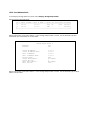
For additional copies of this electronic manual, order Netopia part number 6161090-PF-02.
Printed Copies
For printed copies of this manual, order Netopia part number TER/Doc
(P/N 6161090-00-02).
Contents
Contents
1
Chapter 1 — Introduction..........................................................1-1
Overview ....................................................................... 1-1
Features and capabilities ............................................... 1-1
How to use this guide .................................................... 1-2
Chapter 2 — Making the Physical Connections..........................2-1
Find a location............................................................... 2-1
What you need .............................................................. 2-1
Identify the connectors and attach the cables .................. 2-2
Netopia 4541/4542 ADSL Router status lights................ 2-3
Chapter 3 — Sharing the Connection.........................................3-1
Configuring TCP/IP on Windows-based Computers............ 3-1
Dynamic configuration (recommended)................... 3-2
Static configuration (optional)................................ 3-3
Configuring TCP/IP on Macintosh Computers ................... 3-5
Dynamic configuration (recommended)................... 3-5
Static configuration (optional)................................ 3-6
Chapter 4 — Connecting to Your Local Area Network .................4-1
Readying computers on your local network....................... 4-1
Connecting to an Ethernet network.................................. 4-2
Chapter 5 — Console-Based Management .................................5-1
Connecting through a Telnet session ............................... 5-2
Configuring Telnet software ................................... 5-3
Connecting a console cable to your router ....................... 5-3
Navigating through the console screens .......................... 5-4
Chapter 6 — Easy Setup ...........................................................6-1
Easy Setup console screens........................................... 6-1
Accessing the Easy Setup console screens ............ 6-1
Quick Easy Setup connection path .................................. 6-2
DSL Line Configuration ......................................... 6-3
Easy Setup Profile ................................................ 6-4
G
2
User’s Reference Guide
IP Easy Setup ...................................................... 6-5
Easy Setup Security Configuration ......................... 6-7
Chapter 7 — WAN and System Configuration .............................7-1
WAN configuration.......................................................... 7-1
Creating a new Connection Profile ................................... 7-4
The default profile.......................................................... 7-7
IP parameters (default profile) screen .................... 7-8
Scheduled connections .................................................. 7-8
Viewing scheduled connections ............................. 7-9
Adding a scheduled connection ........................... 7-10
Set Weekly Schedule .......................................... 7-11
Set Once-Only Schedule...................................... 7-12
Modifying a scheduled connection ....................... 7-13
Deleting a scheduled connection ......................... 7-13
System configuration screens ...................................... 7-13
Navigating through the system configuration screens...... 7-14
System configuration features ............................. 7-15
IP setup............................................................. 7-16
Filter sets (firewalls) ........................................... 7-16
IP address serving ............................................. 7-16
Date and time.................................................... 7-16
Console configuration ......................................... 7-17
SNMP (Simple Network Management Protocol) ..... 7-17
Security ............................................................. 7-18
Upgrade feature set ........................................... 7-18
Logging ............................................................. 7-18
Installing the Syslog client .................................. 7-19
Chapter 8 — IP Setup ...............................................................8-1
IP Setup........................................................................ 8-2
IP subnets ........................................................... 8-4
Static routes........................................................ 8-6
IP Address Serving ...................................................... 8-10
Contents
IP Address Pools ................................................
DHCP NetBIOS Options.......................................
More Address Serving Options......................................
Configuring the IP Address Server options............
DHCP Relay Agent........................................................
Connection Profiles ......................................................
3
8-13
8-15
8-17
8-18
8-23
8-25
Chapter 9 — Multiple Network Address Translation ...................9-1
Overview ....................................................................... 9-1
Features.............................................................. 9-1
Supported traffic.................................................. 9-5
MultiNAT Configuration ................................................... 9-5
Easy Setup Profile configuration ............................ 9-6
Server Lists and Dynamic NAT configuration ........... 9-6
IP setup............................................................... 9-7
Modifying map lists ............................................ 9-12
Adding Server Lists...................................................... 9-14
Modifying server lists ......................................... 9-17
Deleting a server ............................................... 9-19
Binding Map Lists and Server Lists ............................... 9-20
IP profile parameters .......................................... 9-20
IP Parameters (WAN Default Profile)..................... 9-22
NAT Associations ......................................................... 9-24
MultiNAT Configuration Example .................................... 9-26
Chapter 10 — Virtual Private Networks (VPNs)........................10-1
Overview ..................................................................... 10-1
About PPTP Tunnels ..................................................... 10-3
PPTP configuration.............................................. 10-4
About IPsec Tunnels..................................................... 10-7
Configuration ..................................................... 10-7
IP Profile Parameters ........................................ 10-10
Advanced IP Profile Options............................... 10-11
Interoperation with other features...................... 10-12
G
4
User’s Reference Guide
About ATMP Tunnels...................................................
ATMP configuration...........................................
Encryption Support ....................................................
MS-CHAP V2 and 128-bit strong encryption........
ATMP/PPTP Default Profile..........................................
VPN QuickView ..........................................................
Dial-Up Networking for VPN .........................................
Installing Dial-Up Networking .............................
Creating a new Dial-Up Networking profile ..........
Configuring a Dial-Up Networking profile .............
Installing the VPN Client .............................................
Windows 95 VPN installation.............................
Windows 98 VPN installation.............................
Connecting using Dial-Up Networking .................
Allowing VPNs through a Firewall .................................
PPTP example ..................................................
ATMP example .................................................
10-12
10-12
10-15
10-15
10-16
10-17
10-18
10-18
10-19
10-20
10-21
10-21
10-22
10-23
10-23
10-24
10-26
Chapter 11 — Security ...........................................................11-1
Suggested security measures ....................................... 11-1
User accounts ............................................................. 11-1
Telnet access .............................................................. 11-3
About filters and filter sets ........................................... 11-4
What’s a filter and what’s a filter set?.................. 11-4
How filter sets work............................................ 11-4
How individual filters work................................... 11-6
Design guidelines............................................. 11-11
Working with IP filters and filter sets............................ 11-12
Adding a filter set ............................................. 11-12
Deleting a filter set........................................... 11-17
A sample filter set ............................................ 11-17
Firewall tutorial .......................................................... 11-20
General firewall terms ...................................... 11-20
Contents
Basic IP packet components .............................
Basic protocol types .........................................
Firewall design rules.........................................
Filter basics .....................................................
Example filters .................................................
5
11-21
11-21
11-22
11-24
11-25
Chapter 12 — Monitoring Tools ...............................................12-1
Quick View status overview .......................................... 12-1
General status ................................................... 12-2
Current status ................................................... 12-3
Status lights ...................................................... 12-3
Statistics & Logs ......................................................... 12-4
Event histories ............................................................ 12-4
IP Routing Table........................................................... 12-7
General Statistics ........................................................ 12-7
System Information...................................................... 12-9
SNMP ......................................................................... 12-9
The SNMP Setup screen ................................... 12-10
SNMP traps ..................................................... 12-11
Chapter 13 — Utilities and Diagnostics ...................................13-1
Ping ............................................................................ 13-2
Trace Route................................................................. 13-4
Telnet client................................................................. 13-5
Factory defaults........................................................... 13-6
Transferring configuration and firmware files with TFTP.... 13-7
Updating firmware .............................................. 13-7
Downloading configuration files ........................... 13-8
Uploading configuration files ............................... 13-9
Transferring configuration and firmware files with
XMODEM..................................................................... 13-9
Updating firmware ............................................ 13-10
Downloading configuration files ......................... 13-11
Uploading configuration files ............................. 13-11
G
6
User’s Reference Guide
Restarting the system................................................ 13-12
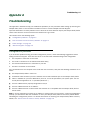
Appendix A — Troubleshooting..................................................A-1
Configuration problems .................................................. A-1
Console connection problems ............................... A-2
Network problems ................................................ A-2
How to reset the router to factory defaults ...................... A-3
Power outages............................................................... A-3
Technical support .......................................................... A-4
How to reach us................................................... A-4
Appendix B — Technical Specifications and Safety Information ..B-1
Description.................................................................... B-1
Power requirements ............................................. B-1
Environment ........................................................ B-1
Software and protocols......................................... B-1
Agency approvals........................................................... B-1
Regulatory notices ............................................... B-2
Important safety instructions ................................ B-4
Limited Warranty and Limitation of Remedies-Revised January 2002
Introduction 1-1
Chapter 1
Introduction
Overview
The Netopia 4541/4542 ADSL Router is a full-featured, stand-alone DSL router for connecting diverse local
area networks (LANs) to the Internet and other remote networks. The Netopia 4541/4542 ADSL Router uses a
high performance telecommunications line to provide your whole network with a high-speed connection to the
outside world. Model 4541 is designed for North American users; model 4542 is designed for non-North
American users. Both support the same features.
This section covers the following topics:
■
“Features and capabilities” on page 1-1
■
“How to use this guide” on page 1-2
Features and capabilities
The Netopia 4541/4542 ADSL Router provides the following features:
■
Support for IP routing for Internet and Intranet connectivity
■
ADSL WAN interface supports symmetric data rates from 144 kbps to 2.32 Mbps
■
Built-in VPN features offer secure Internet connections between remote offices and travelers
■
Built-in firewall protects LAN resources from Internet intruders
■
Support for Ethernet LANs with multiple Ethernet IP subnets
■
10/100-Base T Ethernet port connects easily to an existing LAN hub
■
Interoperable with a wide array of DSLAM equipment
■
Console-based Telnet client
■
UNIX syslog client
■
Status lights (LEDs) for easy monitoring and troubleshooting
■
Support for Console-based management
■
NAT/NATP, multi-NAT, and DHCP for security and convenience
■
Wall-mountable, Bookshelf (Side-stackable), or Desktop-stackable design for efficient space usage
1-2 User’s Reference Guide
How to use this guide
In addition to the simple documentation contained in the accompanying Getting Started Guide, this guide is
designed to be your single source for information about your Netopia 4541/4542 ADSL Router. It is intended to
be viewed on-line, using the powerful features of the Adobe Acrobat Reader. The information display has been
deliberately designed to present the maximum information in the minimum space on your screen. You can keep
this document open while you perform any of the procedures described, and find useful information about the
procedure you are performing.
You can also print out all of the manual, or individual sections, if you prefer to work from hard copy rather than
on-line documentation. The pages are formatted to print on standard 8 1/2 by 11 inch paper. We recommend
that you print on 3-hole punched paper, so that you can put the pages in a binder for future reference. For your
convenience, a printed copy is available from Netopia. Order part number TE4541/Doc.
This guide is organized into chapters describing the Netopia 4541/4542’s advanced features. You may want to
read each chapter’s introductory section to familiarize yourself with the various features available.
Use the guide’s table of contents and index to locate informational topics.
Making the Physical Connections 2-1
Chapter 2
Making the Physical Connections
This section tells you how to make the physical connections to your Netopia 4541/4542 ADSL Router. This
section covers the following topics:
■
“Find a location” on page 2-1
■
“What you need” on page 2-1
■
“Identify the connectors and attach the cables” on page 2-2
■
“Netopia 4541/4542 ADSL Router status lights” on page 2-3
Find a location
When choosing a location for the Netopia ADSL Router, consider:
■
Available space and ease of installation
■
Physical layout of the building and how to best use the physical space available for connecting your Netopia
ADSL Router to the LAN
■
Available wiring and jacks
■
Distance from the point of installation to the next device (length of cable or wall wiring)
■
Ease of access to the front of the unit for configuration and monitoring
■
Ease of access to the back of the unit for checking and changing cables
■
Cable length and network size limitations when expanding networks
For small networks, install the Netopia 4541/4542 near one of the LANs. For large networks, you can install
the Netopia 4541/4542 in a wiring closet or a central network administration site.
What you need
Locate all items that you need for the installation.
Included in your router package are:
■
The Netopia 4541/4542 ADSL Router
■
A power adapter and cord with a mini-DIN8 connector
■
One Category 5 Ethernet cable
■
One Category 5 DSL WAN (or Line) cable
■
A DB-9 to DB-9 console cable
■
The Netopia CD containing software and documentation
2-2 User’s Reference Guide
You will need:
■
A Windows 95 or 98–based PC or a Macintosh computer with Ethernet connectivity for configuring the
Netopia 4541/4542. This may be built-in Ethernet or an add-on card, with TCP/IP installed and configured.
See “Sharing the Connection” on page 3-1.
■
An ADSL wall outlet wired for a connection to a Local Exchange Carrier (LEC) who supports Symmetric
Digital Subscriber Line connections.
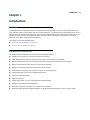
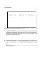
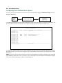
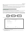
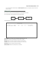
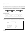
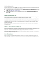
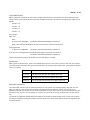
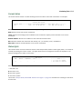
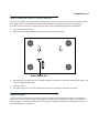
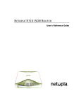
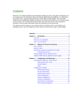
Identify the connectors and attach the cables
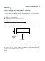
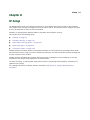
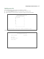
Identify the connectors and switches on the back panel and attach the necessary Netopia Router cables.
The figure below displays the back of the Netopia 4541/4542 ADSL Router.
Netopia 4541/4542 back panel
ADSL port
DSL
Ethernet port
10/100
Ethernet
Console
Power
Power port
Console port
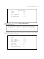
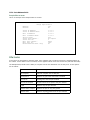
.
Port
Power port
Console port
DSL port
Ethernet port
Description
A mini-DIN8 power adapter cable connection.
A DB-9 console port for a direct serial connection to the console screens. You
can use this if you are an experienced user. See “Connecting a console cable to
your router” on page 5-3.
An RJ-48 jack labeled DSL for your ADSL connection.
An RJ-45 10/100Base-T Ethernet jack. You will use this to configure the Netopia
4541/4542. For a new installation, use the Ethernet connection. Alternatively,
you can use the console connection to run console-based management using a
direct serial connection. You can either connect your computer directly the
Ethernet port using a crossover cable, or connect both your computer and the
Netopia 4541/4542 to an existing Ethernet hub on your LAN.
1.
Connect the mini-DIN8 connector from the power adapter to the power port, and plug the other end into an
electrical outlet.
2.
Connect one end of the Category 5 cable to the DSL port, and the other end to your DSL wall outlet.
Making the Physical Connections 2-3
3.
Connect the Ethernet cable to the Ethernet port on the router and the other end to your computer.
You should now have: the power adapter plugged in; the Ethernet cable connected between the router and
your computer; and the DSL cable connected between the router and the DSL wall outlet.
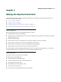
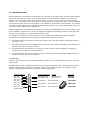
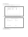
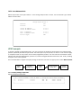
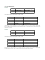
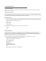
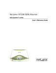
Netopia 4541/4542 ADSL Router status lights
The figure below represents the Netopia 4541/4542 status light (LED) panel.
D
S
L
E
th
e
r
n
e
t
E
r
r
o
r
P
o
w
e
r
Netopia 4541/4542 LED front panel
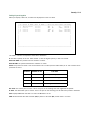
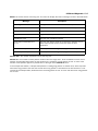
The following table summarizes the meaning of the various LED states and colors:
When this happens...
The power is on
The Router detects an error
The Ethernet link is established
The WAN has trained
The WAN is training
Note: The remaining LEDs are not used.
the LEDs...
Power is green.
Error is red.
Ethernet is green.
DSL is green.
DSL flashes green.
2-4 User’s Reference Guide
Sharing the Connection 3-1
Chapter 3
Sharing the Connection
Once you have set up your physical local area network, you will need to configure the TCP/IP stack on each
client workstation connected to your Netopia 4541/4542. This chapter describes how to configure TCP/IP for
both Windows-based and Macintosh computers.
This chapter explains the following topics:
■
“Configuring TCP/IP on Windows-based Computers” on page 3-1
■
“Configuring TCP/IP on Macintosh Computers” on page 3-5
Configuring TCP/IP on Windows-based Computers
Configuring TCP/IP on a Windows computer requires the following:
■
An Ethernet card (also known as a network adapter)
■
The TCP/IP protocol must be “bound” to the adapter or card
3-2 User’s Reference Guide
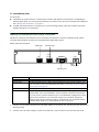
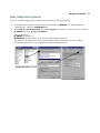
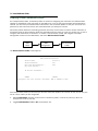
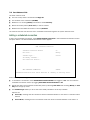
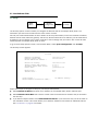
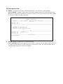
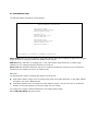
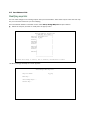
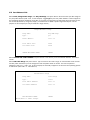
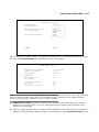
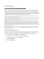
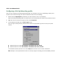
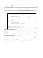
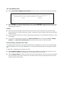
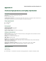
Dynamic configuration (recommended)
To configure your PC for dynamic addressing do the following:
1.
Go to the Start
Menu/Settings/Control
Panels and double click
the Network icon. From
the Network components
list, select the
Configuration tab.
2.
Select TCP/IP-->Your Network Card. Then select
Properties. In the TCP/IP Properties screen, select the IP
Address tab. Click “Obtain an IP Address automatically”.
3.
Click on the DNS Configuration tab. Click Disable DNS.
DNS will be assigned by the router with DHCP.
4.
Click OK in this window and the next window. When
prompted, reboot the computer.
Note: You can also use these instructions to configure other computers on your network to accept IP addresses
served by the Netopia 4541/4542.
Sharing the Connection 3-3
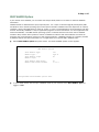
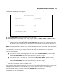
Static configuration (optional)
If you are manually configuring for a fixed or static IP address, perform the following:
1.
Go to Start Menu/Settings/Control Panels and double click the Network icon. From the Network
components list, select the Configuration tab.
2.
Select TCP/IP-->Your Network Card. Then select Properties. In the TCP/IP Properties screen, select the
IP Address tab. Click “Specify an IP Address.”
Enter the following:
IP Address: 192.168.1.2
Subnet Mask: 255.255.255.0, or for 12-user models 255.255.255.240
This address is an example of one that can be used to configure the router. Your ISP or network
administrator may ask you to use a different IP address and subnet mask.
3-4 User’s Reference Guide
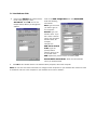
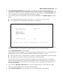
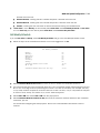
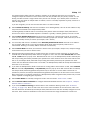
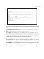
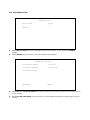
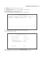
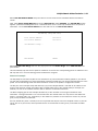
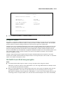
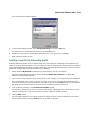
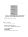
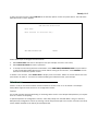
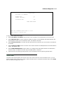
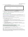
3.
Click on the Gateway tab (shown below).
Under “New gateway,” enter
192.168.1.1. Click Add. This is the
Netopia 4541/4542’s pre-assigned IP
address.
Click on the DNS Configuration tab. Click Enable DNS.
Enter the following
information:
Host: Type the name
you want to give to
this computer.
Domain: Type your
domain name. If you
don't have a domain
name, type your ISP's
domain name; for
example,
netopia.com.
DNS Server Search
Order: Type the
primary DNS IP
address given to you
by your ISP. Click
Add. Repeat this process for the secondary DNS.
Domain Suffix Search Order: Enter the same domain
name you entered above.
4.
Click OK in this window and the next window. When prompted, reboot the computer.
Note: You can also use these instructions to configure other computers on your network with manual or static
IP addresses. Be sure each computer on your network has its own IP address.
Sharing the Connection 3-5
Configuring TCP/IP on Macintosh Computers
The following is a quick guide to configuring TCP/IP for MacOS computers. Configuring TCP/IP in a Macintosh
computer requires the following:
You must have either Open Transport or Classic Networking (MacTCP) installed.
■
Note: If you want to use the Dynamic Host Configuration Protocol (DHCP) server built into your Netopia
4541/4542 to assign IP addresses to your Macintoshes, you must be running Open Transport, standard in
MacOS 8 and optional in earlier system versions. You can have your Netopia 4541/4542 dynamically
assign IP addresses using MacTCP; however, to do so requires that the optional AppleTalk kit be installed
which can only be done after the router is configured.
You must have built-in Ethernet or a third-party Ethernet card and its associated drivers installed in your
Macintosh.
■
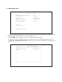
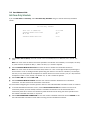
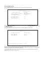
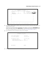
Dynamic configuration (recommended)
The Dynamic Host Configuration Protocol (DHCP), which enables dynamic addressing, is enabled by default in
the router. To configure your Macintosh computer for dynamic addressing do the following:
1.
Go to the Apple menu. Select Control Panels and then
TCP/IP.
2.
With the TCP/IP window open, go to the Edit menu and
select User Mode. Choose Basic and click OK.
3.
In the TCP/IP window, select “Connect via: Ethernet” and
“Configure: Using DHCP Server.”
Note: You can also use these instructions to configure other computers on your network to accept IP addresses
served by the Netopia 4541/4542.
3-6 User’s Reference Guide
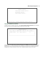
Static configuration (optional)
If you are manually configuring for a fixed or static IP address,
perform the following:
1.
Go to the Apple menu. Select Control Panels and then
TCP/IP or MacTCP.
2.
With the TCP/IP window open, go to the Edit menu and
select User Mode. Choose Advanced and click OK.
Or, in the MacTCP window, select Ethernet and click the
More button.
3.
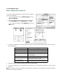
In the TCP/IP window or in the MacTCP/More window, select or type information into the fields as shown in
the following table.
Option:
Connect via:
Configure:
IP Address:
Subnet mask:
Router or Gateway address:
Name server address:
Implicit Search Path:
Starting domain name:
Select/Type:
Ethernet
Manually
192.168.1.2
255.255.255.0, or for 12-user models
255.255.255.240
192.168.1.1
Enter the primary and secondary name server
addresses given to you by your ISP
Enter your domain name; if you do not have a
domain name, enter the domain name of your ISP
4.
Close the TCP/IP or MacTCP control panel and save the settings.
5.
If you are using MacTCP, you must restart the computer. If you are using Open Transport, you do not need
to restart.
Note: You can also use these instructions to configure other computers on your network to accept IP addresses
served by the Netopia 4541/4542.
Sharing the Connection 3-7
Note: You can also use these instructions to configure other computers on your network with manual or static
IP addresses. Be sure each computer on your network has its own IP address.
More information about configuring your Macintosh computer for TCP/IP connectivity through a Netopia
4541/4542 can be found in Technote NIR_026, “Open Transport and Netopia Routers,” located on the Netopia
Web site.
3-8 User’s Reference Guide
Connecting to Your Local Area Network 4-1
Chapter 4
Connecting to Your Local Area Network
This chapter describes how to physically connect the Netopia 4541/4542 to your local area network (LAN).
Before you proceed, make sure the Netopia 4541/4542 is properly configured. You can customize the router’s
configuration for your particular LAN requirements using console-based management (see “Console-Based
Management” on page 5-1).
This section covers the following topics:
■
“Readying computers on your local network” on page 4-1
■
“Connecting to an Ethernet network” on page 4-2
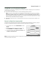
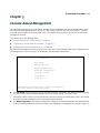
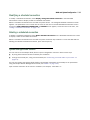
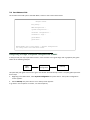
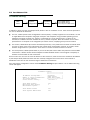
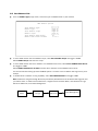
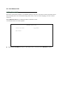
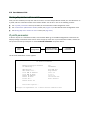
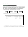
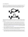
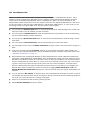
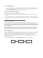
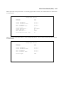
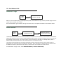
Readying computers on your local network
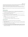
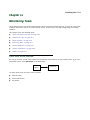
PC and Macintosh computers must have certain components installed before they can communicate through
the Netopia 4541/4542. The following illustration shows the minimal requirements for a typical PC or
Macintosh computer.
Application software
TCP/IP stack
Ethernet Driver
Your PC
or Macintosh
computer
To the Netopia
Application software: This is the software you use to send e-mail, browse the World Wide Web, read
newsgroups, etc. These applications may require some configuration. Examples include the Eudora e-mail client
and the Web browsers Microsoft Internet Explorer and Netscape Navigator.
TCP/IP stack: This is the software that lets your PC or Macintosh computer communicate using Internet
protocols. TCP/IP stacks must be configured with some of the same information you used to configure the
Netopia 4541/4542. There are a number of TCP/IP stacks available for PC computers. Windows 95 includes a
built-in TCP/IP stack. Macintosh computers use either MacTCP or Open Transport. See “Configuring TCP/IP on
Windows-based Computers” on page 3-1. Macintosh computers use either MacTCP or Open Transport. See
“Configuring TCP/IP on Macintosh Computers” on page 3-5.
Ethernet: Ethernet hardware and software drivers enable your PC or Macintosh computer to communicate on
the LAN.
4-2 User’s Reference Guide
Once the Netopia 4541/4542 is properly configured and connected to your LAN, PC and Macintosh computers
that have their required components in place will be able to connect to the Internet or other remote IP networks.
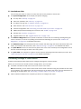
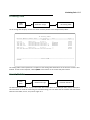
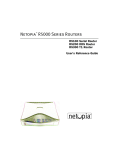
Connecting to an Ethernet network
The Netopia 4541/4542 supports Ethernet connections through its Ethernet port. You can connect a standard
10 or 100Base-T Ethernet network to the Netopia 4541/4542 using its Ethernet port.
Netopia 4541/4542 back panel
DSL
10/100
Ethernet
Console
The Netopia 4541/4542 in a 10Base-T network
To connect your 10Base-T network to the Netopia
4541/4542 through the Ethernet port, use a
10Base-T cable with RJ-45 connectors.
If you have more than one device to connect, you
can attach additional devices using a cross-over
cable (not provided) or you can connect through a
switch or repeater.
10/100
Ethernet
Power
Console-Based Management 5-1
Chapter 5
Console-Based Management
Console-based management is a menu-driven interface for the capabilities built into the Netopia 4541/4542.
Console-based management provides access to a wide variety of features that the router supports. You can
customize these features for your individual setup. This chapter describes how to access the console-based
management screens.
This section covers the following topics:
■
“Connecting through a Telnet session” on page 5-2
■
“Connecting a console cable to your router” on page 5-3
■
“Navigating through the console screens” on page 5-4
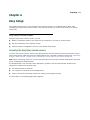
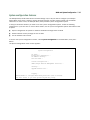
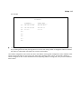
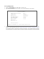
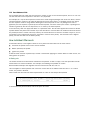
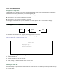
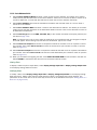
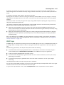
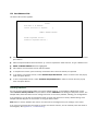
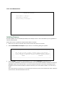
Console-based management screens contain seven entry points to the Netopia 4541/4542 configuration and
monitoring features. The entry points are displayed in the Main Menu shown below:
Netopia 4541
Easy Setup...
WAN Configuration...
System Configuration...
Utilities & Diagnostics...
Statistics & Logs...
Quick Menus...
Quick View...
Return/Enter goes to Easy Setup -- minimal configuration.
You always start from this main screen.
■
The Easy Setup menus display and permit changing the values contained in the default connection profile.
You can use Easy Setup to initially configure the router directly through a console session.
Easy Setup menus contain up to five descendant screens for viewing or altering these values. The number
of screens depends on whether you have optional features installed.
■
The WAN Configuration menu displays and permits changing your connection profile(s) and default profile,
creating or deleting additional connection profiles, and configuring or reconfiguring the manner in which you
5-2 User’s Reference Guide
may be using the router to connect to more than one service provider or remote site.
■
The System Configuration menus display and permit changing:
■
IP setup. See “IP Setup” on page 8-1.
■
Filter sets (firewalls). See “Security” on page 11-1.
■
IP address serving. See “IP Address Serving” on page 8-10.
■
Date and time. See “Date and time” on page 7-16.
■
Console configuration. See “Connecting a console cable to your router” on page 5-3.
■
SNMP (Simple Network Management Protocol). See “SNMP” on page 12-9.
■
Security. See “Security” on page 11-1.
■
Upgrade feature set. See “Upgrade feature set” on page 7-18.
■
The Utilities & Diagnostics menus provide a selection of seven tools for monitoring and diagnosing the
router's behavior, as well as for updating the firmware and rebooting the system. See “Utilities and
Diagnostics” on page 13-1 for detailed information.
■
The Statistics & Logs menus display nine sets of tables and device logs that show information about your
router, your network, and their history. See “Statistics & Logs” on page 12-4 for detailed information.
■
The Quick Menus screen is a shortcut entry point to 22 of the most commonly used configuration menus
that are accessed through the other menu entry points.
■
The Quick View menu displays at a glance current real-time operating information about your router. See
“Quick View status overview” on page 12-1 for detailed information.
Connecting through a Telnet session
Features of the Netopia 4541/4542 can be configured through the console screens.
Before you can access the console screens through Telnet, you must have:
■
A network connection locally to the router or IP access to the router.
Note: Alternatively, you can have a direct serial console cable connection using the provided console cable
for your platform (PC or Macintosh) and the Console port on the back of the router. For more information on
attaching the console cable, see “Connecting a console cable to your router” on page 5-3.
■
Telnet software installed on the computer you will use to configure the router
Console-Based Management 5-3
Configuring Telnet software
If you are configuring your router using a Telnet session, your computer must be running a Telnet software
program.
■
If you connect a PC with Microsoft Windows, you can use a Windows Telnet application or simply run Telnet
from the Start menu.
■
If you connect a Macintosh computer, you can use the NCSA Telnet program supplied on the Netopia
4541/4542 CD. You install NCSA Telnet by simply dragging the application from the CD to your hard disk.
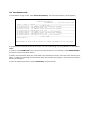
Connecting a console cable to your router
You can perform all of the system configuration activities for your Netopia 4541/4542 through a local serial
console connection using terminal emulation software, such as HyperTerminal provided with Windows 95, 98,
2000, or NT on the PC, or ZTerm, included on the Netopia CD, for Macintosh computers.
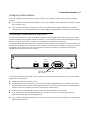
The Netopia 4541/4542 back panel has a connector labeled “Console” for attaching the Router to either a PC
or Macintosh computer via the serial port on the computer. (On a Macintosh computer, the serial port is called
the Modem port or Printer port.) This connection lets you use the computer to configure and monitor the
Netopia 4541/4542 via the console screens.
DSL
10/100
Ethernet
Console
Power
Console connection port
DB-9 (male)
To connect the Netopia 4541/4542 to your computer for serial console communication, use a console cable
appropriate to your platform:
■
A DB-9 connector end attaches to a PC.
■
A mini-DIN8 connector end attaches to a Macintosh computer depending on your computer’s serial bus
type. Since Macintosh computers have different serial bus connectors, you will need a mini-DIN8-to-DB-9
adapter. These are available from a variety of third-party manufacturers.
■
A DB-9 end of the Console cable attaches to the Netopia 4541/4542’s Console port.
■
If you connect a PC with Microsoft Windows 95, 98, 2000, or NT, you can use the HyperTerminal
application bundled with the operating system.
■
If you connect a Macintosh computer, you can use the ZTerm terminal emulation program on the supplied
Netopia 4541/4542 CD.
5-4 User’s Reference Guide
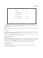
Launch your terminal emulation software and configure the communications software for the values shown in
the table below. These are the default communication parameters that the Netopia 4541/4542 uses.
Parameter
Suggested Value
Terminal type
PC: ANSI-BBS
Mac: ANSI, VT-100, or VT-200
Data bits
8
Parity
None
Stop bits
1
Speed
9600 - 57600 bits per second
Flow Control
None
Note: The router firmware contains an autobaud detection feature. If you are at any
screen on the serial console, you can change your baud rate and press Return
(HyperTerminal for the PC requires a disconnect). The new baud rate is displayed at
the bottom of the screen.
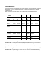
Navigating through the console screens
Use your keyboard to navigate the Netopia 4541/4542’s configuration screens, enter and edit information, and
make choices. The following table lists the keys to use to navigate through the console screens.
To...
Use These Keys...
Move through selectable items in a screen or pop-up menu
Up, Down, Left, and Right Arrow
Set a change to a selected item or open a pop-up menu of
options for a selected item like entering an upgrade key
Return or Enter
Change a toggle value (Yes/No, On/Off)
Tab
Restore an entry or toggle value to its previous value
Esc
Move one item up
Up arrow or Control + K
Move one item down
Down arrow or Control + O
Display a dump of the device event log
Control + E
Display a dump of the WAN event log
Control + F
Refresh the screen
Control + L
Easy Setup 6-1
Chapter 6
Easy Setup
This chapter describes how to use the Easy Setup console screens on your Netopia 4541/4542. After
completing the Easy Setup console screens, your router will be ready to connect to the Internet or another
remote site.
Easy Setup console screens
Using four Easy Setup console screens, you can:
■
Modify a connection profile for your router for the connection to your ISP or remote location
■
Set up IP addresses and IP address serving
■
Password–protect configuration access to your Netopia 4541/4542
Accessing the Easy Setup console screens
To access the console screens, Telnet to the Netopia Router over your Ethernet network or physically connect
with a serial console cable and access the Netopia Router with a terminal emulation program. See “Connecting
through a Telnet session” on page 5-2 or “Connecting a console cable to your router” on page 5-3.
Note: Before continuing, make sure you have the information that your ISP or network administrator has given
you for configuring the Netopia Router.
The Netopia Router’s first console screen, Main Menu, appears in the terminal emulation window of the
attached PC or Macintosh computer when:
■
The Netopia Router is turned on
■
The computer is connected to the Netopia Router
■
Telnet or the terminal emulation software is running and configured correctly
A screen similar to the following Main Menu appears:
6-2 User’s Reference Guide
Netopia Router
Easy Setup...
WAN Configuration...
System Configuration...
Utilities & Diagnostics...
Statistics & Logs...
Quick Menus...
Quick View...
If you do not see the Main Menu, verify that:
■
If you are using a serial connection, that your serial port speed is the same as the Netopia 4541/4542’s
default 9600 baud, for first use.
■
The computer used to view the console screen has its serial port connected to the Netopia 4541/4542’s
Console port or an Ethernet connection to one of its Ethernet ports. See “Connecting a console cable to
your router” on page 5-3 or “Connecting through a Telnet session” on page 5-2.
■
Telnet or the terminal emulation software is configured for the recommended values.
■
If you are connecting via the Console port, your computer’s serial port is not being used by another device,
such as an internal modem, or an application. Turn off all other programs (other than your terminal
emulation program) that may be interfering with your access to the port.
■
You have entered the correct password, if necessary. Your Netopia 4541/4542’s console access may be
password protected from a previous configuration. See your system administrator to obtain the password.
See Appendix A, “Troubleshooting,” for more suggestions.
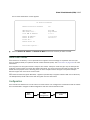
Quick Easy Setup connection path
If your ISP assigns your Router a Static IP address, do the following:
1.
Open a Telnet session to 192.168.1.1 to bring up the Main Menu.
If you don't know how to do this, see “Connecting through a Telnet session” on page 5-2.
Alternatively, you can connect the console cable and open a direct serial console connection, using a
terminal emulator program. See “Connecting a console cable to your router” on page 5-3.
Easy Setup 6-3
The Main Menu appears.
Netopia Router
Easy Setup...
WAN Configuration...
System Configuration...
Utilities & Diagnostics...
Statistics & Logs...
Quick Menus...
Quick View...
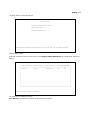
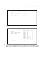
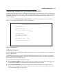
2.
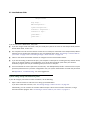
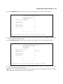
Select the first item on the Main Menu list, Easy Setup. Press Return to bring up the ADSL Line
Configuration menu screen.
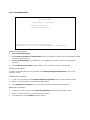
DSL Line Configuration
ADSL Line Configuration
Circuit Type...
Multimode
Data Link Encapsulation...
RFC1483 Mode...
PPP over Ethernet (PPPoE):
RFC1483
Bridged 1483
Off
Data Circuit VPI (0-255):
Data Circuit VCI (0-65535):
8
35
PREVIOUS SCREEN
NEXT SCREEN
1.
Select Circuit Type and, from the pop-up menu, choose the type of circuit to which you will be connecting:
Multimode, T1.413, G.dmt, G.lite, or ADI.
2.
Select Data Link Encapsulation and from the pop-up menu choose either RFC1483 (the default) or PPP.
■
If you selected RFC1483, the next pop-up menu RFC1483 Mode offers the choice of Bridged 1483 or
6-4 User’s Reference Guide
Routed 1483. If you select Bridged 1483, a new option PPP over Ethernet (PPPoE) appears. You can
then toggle PPPoE On or Off. Choosing Routed 1483 hides the PPPoE option.
■
If you selected PPP, the next pop-up menu PPP Mode offers the choice of VC Multiplexed or LLC SNAP.
3.
The next two fields, Data Circuit VPI and Data Circuit VCI are editable. Enter the Virtual Path Identifier and
Virtual Channel Identifier values that your provider specifies.
4.
Press the Down arrow key until you reach NEXT SCREEN. Press Return to bring up the next screen.
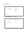
Easy Setup Profile
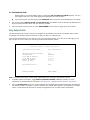
The Easy Setup Profile screen is where you configure the parameters that control the Netopia 4541/4542’s
connection to a specific remote destination, usually your ISP or a corporate site.
On a Netopia 4541/4542 you can add up to 15 more connection profiles, for a total of 16, although you can
only use one at a time, unless you are using Virtual Private Networks (VPNs).
Connection Profile 1: Easy Setup Profile
Connection Profile Name:
Easy Setup Profile
Address Translation Enabled:
IP Addressing...
Yes
Numbered
Local WAN
Local WAN
Remote IP
Remote IP
0.0.0.0
0.0.0.0
0.0.0.0
0.0.0.0
IP Address:
IP Mask:
Address:
Mask:
PPP Authentication...
None
PREVIOUS SCREEN
NEXT SCREEN
Note: The appearance of this screen varies, depending on the settings in the previous screen.
1.
To enable address translation, toggle Address Translation Enabled to Yes (the default). For more
information on Network Address Translation, see Chapter 9, “Multiple Network Address Translation.”
2.
From the IP Addressing menu item, choose between Unnumbered and Numbered addressing. Numbered is
the default for ADSL. It assigns a unique IP address to the ADSL WAN interface, as required by most ISPs’
routers. Unnumbered may be used for simpler configurations such as point-to-point applications.
Easy Setup 6-5
If you selected Numbered, the following fields appear.
■
Select the editable field labeled Local WAN IP Address.
The default address is 0.0.0.0, which allows for dynamic addressing, when your ISP assigns an address
each time you connect. However, you can enter another specific address if you want to use static
addressing. In that case, enter the local WAN address your ISP gave you. Press Return.
■
Select the editable field labeled Local WAN IP Mask. Enter the mask address your ISP gave you. Press
Return.
If you selected Unnumbered, the following fields appear.
■
Select the editable field labeled Remote IP Address and enter the remote IP address. Press Return.
■
Select the editable field labeled Remote IP Mask and enter the remote mask address. Press Return.
3.
If you selected PPP data link encapsulation in the DSL Line Configuration screen, a PPP Authentication
menu item appears. The authentication protocol and user name/password combinations you enter must
be assigned or agreed to in advance between you and your ISP. Select PPP Authentication and press
Return.
From the pop-up menu that appears, select the authentication method your ISP uses: PAP (Password
Authentication Protocol), CHAP (Challenge Handshake Authentication Protocol), or None.
4.
■
PAP is the most common, and requires you to enter a User Name and Password in the next two fields.
■
CHAP requires you to enter a Host Name and Secret in the next two fields.
Press the Down arrow key until you reach NEXT SCREEN. Press Return to bring up the next screen.
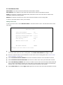
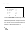
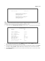
IP Easy Setup
The IP Easy Setup screen is where you enter information about your Netopia Router’s:
■
Ethernet IP address
■
Ethernet Subnet mask
■
Domain Name
■
Domain Name Server IP address
■
Default gateway IP address
Consult with your network administrator to obtain the information you will need. For more information about
setting up IP, see “IP Setup” on page 8-2.
6-6 User’s Reference Guide
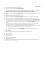
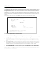
IP Easy Setup
Ethernet IP Address:
Ethernet Subnet Mask:
192.168.1.1
255.255.255.0
Domain Name:
Primary Domain Name Server:
Secondary Domain Name Server:
isp.net
209.3.224.21
209.3.224.20
Default IP Gateway:
127.0.0.2
IP Address Serving:
On
Number of Client IP Addresses:
1st Client Address:
100
192.168.1.100
PREVIOUS SCREEN
NEXT SCREEN
Enter an IP address in decimal and dot form (xxx.xxx.xxx.xxx).
Set up the basic IP & IPX attributes of your Netopia in this screen.
1.
Select Ethernet IP Address and enter the first IP address from the IP address range your ISP has given
you. This will be the Netopia Router’s IP address.
The Ethernet IP Address defaults to an address (192.168.1.1) within a range reserved by the Internet
address administration authority for use within private networks.
Because this is a private network address, it should never be directly connected to the Internet. Using NAT
for all your connection profiles will ensure this restriction. See Chapter 9, “Multiple Network Address
Translation,” for more information.
2.
Select Ethernet Subnet Mask and enter the subnet mask your ISP has given you. The Ethernet Subnet
Mask defaults to a standard class mask derived from the class of the Ethernet IP address you entered in
the previous step.
3.
Press the Down arrow key until the editable field labeled Domain Name is highlighted.
4.
Type the Domain Name your ISP gave you. Press Return. The next field Primary Domain Name Server will
be highlighted.
5.
Type the Primary Domain Name Server address your ISP gave you. Press Return. A new field Secondary
Domain Name Server will appear. If your ISP gave you a secondary domain name server address, enter it
here. Press Return until the next field Default IP Gateway is highlighted.
6.
If you do not enter a Default IP Gateway value, the router defaults to the remote IP address you entered in
the Easy Setup connection profile. If the Netopia Router does not recognize the destination of any IP traffic,
it forwards that traffic to this gateway.
Do not confuse the remote IP address and the Default IP Gateway’s address with the block of local IP
addresses you receive from your ISP. You use the local IP addresses for the Netopia 4541/4542’s
Ethernet port and for IP clients on your local network. The remote IP address and the default gateway’s IP
address should point to your ISP’s router.
Easy Setup 6-7
7.
Toggle IP Address Serving to On or Off, depending on whether you want the device’s IP address server to
supply dynamic IP addresses to your client workstations. Normally, you would accept the default On so that
workstations on your LAN can have IP addresses assigned dynamically from the router.
8.
The IP address server will provide 100 IP addresses automatically to workstations on your LAN. You only
need to change the Number of Client IP Addresses if you have some other IP addressing scheme.
9.
By default, the 1st Client Address is 192.168.1.100, based on the device’s default IP address of
192.168.1.1. You only need to change this if you have some other IP addressing scheme.
10. Press the Down arrow key until you reach NEXT SCREEN. Press Return.
Easy Setup Security Configuration
The Easy Setup Security Configuration screen lets you password-protect your Netopia 4541/4542. Input your
Write Access Name and Write Access Password with names or numbers totaling up to eleven digits.
If you password protect the console screens, you will be prompted to enter the name and password you have
specified every time you log in to the console screens. Do not forget your name and password. If you do, you
will be unable to access any of the configuration screens.
Additional security features are available. See “Security” on page 11-1.
Easy Setup Security Configuration
It is strongly suggested that you password-protect configuration access to your
Netopia. By entering a Name and Password pair here, access via serial,
Telnet, and SNMP will be password-protected.
Be sure to remember what you have typed here, because you will be prompted for
it each time you configure this Netopia.
Write Access Name:
Write Access Password:
PREVIOUS SCREEN
TO MAIN MENU
RESTART DEVICE
Configure a Configuration Access Name and Password here.
The final step in configuring the Easy Setup console screens is to restart the Netopia 4541/4542, so that the
configuration settings take effect.
1.
Select RESTART DEVICE. A prompt asks you to confirm your choice.
2.
Select CONTINUE to restart the Netopia Router and have your selections take effect.
Note: You can also restart the system at any time by using the Restart System utility (see “Restarting the
system” on page 13-12) or by turning the Netopia Router off and on with the power switch.
6-8 User’s Reference Guide
The Router will restart and your configuration settings will be activated. You can then Exit or Quit your Telnet
application.
Easy Setup is now complete.
WAN and System Configuration 7-1
Chapter 7
WAN and System Configuration
This chapter describes how to use the console-based management screens to access and configure advanced
features of your Netopia 4541/4542 ADSL Router. You can customize these features for your individual setup.
These menus provide a powerful method for experienced users to set up their router’s connection profiles and
system configuration.
This section covers the following topics:
■
“WAN configuration” on page 7-1
■
“Creating a new Connection Profile” on page 7-4
■
“The default profile” on page 7-7
■
“Scheduled connections” on page 7-8
■
“System configuration screens” on page 7-13
■
“Navigating through the system configuration screens” on page 7-14
■
“System configuration features” on page 7-15
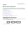
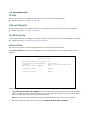
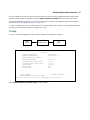
WAN configuration
To configure your Wide Area Network (WAN) connection, navigate to the WAN Configuration screen from the Main
Menu and select WAN (Wide Area Network) Setup.
Main
Menu
WAN
Configuration
The ADSL Line Configuration screen appears.
WAN
Setup
7-2 User’s Reference Guide
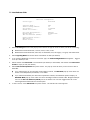
ADSL Line Configuration
Circuit Type...
Multimode
Signaling Mode...
Trellis Coding Enabled:
FDM
On
Cell Format...
Unused Cell Format...
Scrambled
Idle
Data Link Encapsulation...
RFC1483 Mode...
PPP over Ethernet (PPPoE):
RFC1483
Bridged 1483
Off
Display/Change Circuit...
Add Circuit...
Delete Circuit...
1.
Select Circuit Type and from the pop-up menu choose the type of circuit to which you will be connecting.
■
Model 4541 offers Multimode, T1.413, G.dmt, G.lite, or ADI.
■
Model 4542 offers Multimode, ADI ETDI, ITU Standard, UR2, ADI Legacy, TI Legacy and Alcatel ETSI.
2.
Select Signaling Mode and choose Echo Cancellation or FDM (the default).
3.
If you selected Multimode or G.lite as the Circuit Type, the Trellis Coding Enabled field appears. Toggle it
to On (the default) or Off.
4.
Select whether the Cell Format is Unscrambled (the default) or Scrambled, and whether the Unused Cell
Format is Empty or Idle (the default).
5.
Select Data Link Encapsulation and press Return. The pop-up menu will offer you the choice of PPP or
RFC1483.
6.
■
If you selected PPP as your data link encapsulation method, the PPP Mode pop-up menu offers the
choice of VC Multiplexed (the default) or LLC SNAP.
■
If you selected RFC1483 your data link encapsulation method, two additional options display: an
RFC1483 Mode pop-up menu offers the choice of Bridged 1483 or Routed 1483. Bridged 1483 permits use of PPP over Ethernet (PPPoE) and is the default. You can then toggle PPPoE On or Off.
Choosing Routed 1483 hides the PPPoE option.
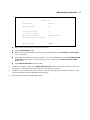
To add a circuit, select Add Circuit and press Return. The Add Circuit screen appears.
WAN and System Configuration 7-3
Add Circuit
Circuit Name:
Circuit 2
Circuit Enabled:
Yes
Circuit VPI (0-255):
0
Circuit VCI (0-65535):
0
Use Connection Profile...
Use Default Profile for Circuit
Default Profile
ADD Circuit NOW
CANCEL
■
Enter a name for the circuit in the Circuit Name field.
■
Toggle Circuit Enabled to Yes.
■
Enter the Virtual Path Identifier and the Virtual Channel Identifier in the Circuit VPI and Circuit VCI
fields, respectively.
■
Then, select a Connection Profile for the Circuit. To use the Default Profile, select Use Default Profile
for Circuit and press Return. For other options, select a profile from the Use Connection Profile
pop-up menu.
■
Select ADD Circuit NOW and press Return.
7.
To display or change a circuit, select Display/Change Circuit, select a cicuit from the pop-up menu, and
press Return. The fields are the same as those in the Add Circuit screen.
8.
To delete a circuit, select Delete Circuit, select a cicuit from the pop-up menu, and press Return. In the
confirmation window, select CONTINUE and press Return.
9.
Press Escape to return to the WAN Setup menu.
7-4 User’s Reference Guide
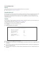
Creating a new Connection Profile
For a Netopia 4541/4542, connection profiles are useful for configuring the connection and authentication
settings for negotiating a PPP connection on the ADSL link. If you are using the PPP data link encapsulation
method, you can store your authentication information in the connection profile so that your user name and
password (or host name and secret) are transmitted when you attempt to connect.
Connection profiles define the networking protocols necessary for the router to make a remote connection. A
connection profile is like an address book entry describing how the router is to get to a remote site, or how to
recognize and authenticate a connection. To create a new connection profile, you navigate to the WAN
Configuration screen from the Main Menu, and select Add Connection Profile.
WAN
Configuration
Main
Menu
Add Connection
Profile
The Add Connection Profile screen appears.
Add Connection Profile
Profile Name:
Profile Enabled:
Profile 1
Yes
Data Link Encapsulation...
Data Link Options...
PPP
IP Profile Parameters...
COMMIT
Configure a new Conn. Profile. Finished?
CANCEL
ADD or CANCEL to exit.
On a Netopia 4541/4542 you can add up to 15 more connection profiles, for a total of 16, but you can only use
one at a time, unless you are using VPNs.
1.
Select Profile Name and enter a name for this connection profile. It can be any name you wish. For
example: the name of your ISP.
2.
Toggle Profile Enabled to Yes or No. The default is Yes.
WAN and System Configuration 7-5
3.
Select Data Link Encapsulation and press Return. The pop-up menu offers the possible data link
encapsulation methods for connection profiles used for a variety of purposes: PPP, RFC1483, ATMP, PPTP,
or IPsec. If you select any data link encapsulation method other than RFC1483, a Data Link Options menu
item is displayed; if you select RFC1483, Data Link Options is hidden.
4.
If you chose any data link encapsulation method other than RFC1483, select Datalink Options and press
Return.
■
If you selected ATMP, PPTP, or IPSec, see Chapter 10, “Virtual Private Networks (VPNs).”
■
If you selected PPP, the Datalink (PPP/MP) Options screen appears.
Datalink (PPP/MP) Options
Data Compression...
Standard LZS
Send Authentication...
PAP
Send User Name:
Send Password:
Receive User Name:
Receive Password:
Maximum Packet Size:
1500
In this Screen you will configure the PPP/MP specific connection params.
Select Data Compression and press Return. The pop-up menu offers the choices of None, Ascend LZS, or
Standard LZS. Unless you are otherwise specifically directed, you can accept the default.
Select Send Authentication and press Return.
From the pop-up menu that appears, select the authentication method your ISP uses, if any: PAP (Password
Authentication Protocol), CHAP (Challenge Handshake Authentication Protocol), or None.
■
PAP is the most common, and requires you to enter a User Name and Password in the next two fields.
■
CHAP requires you to enter a Host Name and Secret in the next two fields.
You can specify user name and password for both outgoing and incoming connections. The Send User
Name/Password parameters are used to specify your identity when connecting to a remote location. The
Receive User Name/Password parameters are used when the ISP router requires authentication; this is
not commonly required.
5.
You can edit the Maximum Packet Size field, if you want packets limited to a lower value than 1500.
Return to the Add Connection Profile screen by pressing Escape.
6.
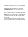
Select IP Profile Parameters and press Return. The IP Profile Parameters screen appears.
7-6 User’s Reference Guide
IP Profile Parameters
Address Translation Enabled:
IP Addressing...
Yes
Numbered
NAT Map List...
NAT Server List...
Easy-PAT List
Easy-Servers
Local WAN IP Address:
Local WAN IP Mask:
0.0.0.0
0.0.0.0
Filter Set...
Remove Filter Set
RIP Profile Options...
7.
Toggle or enter any IP Parameters you require and return to the Add Connection Profile screen by pressing
Escape. For more information, see “IP Setup” on page 8-2.
8.
Select COMMIT and press Return. Your new Connection Profile will be added.
If you want to view the Connection Profiles in your device, return to the WAN Configuration screen, and
select Display/Change Connection Profile. The list of Connection Profiles is displayed in a scrolling pop-up
screen.
WAN Configuration
+-Profile Name---------------------IP Address------+
+--------------------------------------------------+
| Easy Setup Profile
255.225.255.255 |
| Profile 1
0.0.0.0
|
|
|
|
|
|
|
|
|
|
|
|
|
|
|
|
|
|
|
|
|
|
|
|
|
|
|
|
|
+--------------------------------------------------+
WAN and System Configuration 7-7
The default profile
If you are using RFC1483 datalink encapsulation, the Default Profile screen controls whether or not the ADSL
link will come up without an explicitly configured connection profile. (PPP datalink encapsulation does not
support a default profile, and the corresponding menu item is unavailable.) See “Connection Profiles” on
page 8-25 for more information.
You access the Default Profile screen from the Main Menu by selecting WAN Configuration and then selecting
Default Profile.
Main
Menu
WAN
Configuration
WAN
Default Profile
The Default Profile screen appears.
WAN Default Profile
Must Match a Defined Profile:
No
IP Parameters...
■
You can set Must Match a Defined Profile item to Yes or No (the default). This item controls whether or
not the ADSL link will come up without an explicitly configured connection profile. If your ISP is serving you
a dynamic IP Address, you need not explicitly configure a connection profile, and the default behavior of the
router will be to connect automatically once it is powered on.
7-8 User’s Reference Guide
IP parameters (default profile) screen
If you are using RFC1483 datalink encapsulation, the IP Parameters (Default Profile) screen allows you to
configure various IP parameters for ADSL connections established without an explicitly configured connection
profile:
IP Parameters (Default Profile)
Address Translation Enabled:
No
Filter Set (Firewall)...
Remove Filter Set
Receive RIP:
Transmit RIP:
Both
Off
Return/Enter accepts * Tab toggles * ESC cancels.
For an ADSL link, Network Address Translation (NAT) is disabled by default in the Default Profile. You can enable
it by toggling to Yes. For details on setting up IP Parameters see “IP Setup” on page 8-2.
Scheduled connections
Scheduled connections are useful for PPPoE, PPTP, and ATMP connection profiles.
To go to the Scheduled Connections screen, select Scheduled Connections in the WAN Configuration screen.
Main
Menu
WAN
Configuration
Scheduled
Connections
WAN and System Configuration 7-9
Scheduled Connections
Display/Change Scheduled Connection...
Add Scheduled Connection...
Delete Scheduled Connection...
Navigate from here to add/modify/change/delete Scheduled Connections.
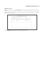
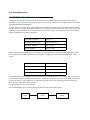
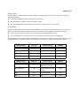
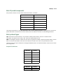
Viewing scheduled connections
To display a table of scheduled connections, select Display/Change Scheduled Connection in the Scheduled
Connections screen. Each scheduled connection occupies one row of the table.
Scheduled Connections
+-Days----Begin At---HH:MM---When----Conn. Prof. Name----Enabled-----+
+--------------------------------------------------------------------+
| mtWtfss 08:30PM
06:00
weekly Profile 01
No
|
|
|
|
|
|
|
|
|
|
|
+--------------------------------------------------------------------+
The first column in the table shows a one-letter representation of the Days of the week, from Monday (M or m)
to Sunday (S or s). If a letter representing a day is capitalized, the connection will be activated on that day; a
lower-case letter means that the connection will not be activated on that day. If the scheduled connection is
configured for a once-only connection, the word “once” will appear instead of the days of the week.
7-10 User’s Reference Guide
The other columns show:
■
The time of day that the connection will Begin At
■
The duration of the connection (HH:MM)
■
Whether it’s a recurring Weekly connection or used Once Only
■
Which connection profile (Conn. Prof.) is used to connect
■
Whether the scheduled connection is currently Enabled
The router checks the date and time set in scheduled connections against the system date and time.
Adding a scheduled connection
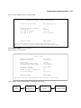
To add a new scheduled connection, select Add Scheduled Connection in the Scheduled Connections screen
and press Return. The Add Scheduled Connection screen appears.
Add Scheduled Connection
Scheduled Connection Enable:
On
How Often...
Weekly
Schedule Type...
Forced
Set Weekly Schedule...
Use Connection Profile...
ADD SCHEDULED CONNECTION
CANCEL
Scheduled Connections dial remote Networks on a Weekly or Once-Only basis.
Follow these steps to configure the new scheduled connection:
■
To activate the connection, select Scheduled Connection Enable and toggle it to On. You can make the
scheduled connection inactive by toggling Scheduled Connection Enable to Off.
■
Decide how often the connection should take place by selecting How Often and choosing Weekly or Once
Only from the pop-up menu.
■
The Schedule Type allows you to set the exact weekly schedule or once-only schedule.
Options are:
■
Forced Up, meaning that this connection will be maintained whether or not there is a demand call on
the line.
■
Forced Down, meaning that this connection will be torn down or blocked whether or not there is a
WAN and System Configuration 7-11
demand call on the line.
■
■
Demand-Allowed, meaning that this schedule will permit a demand call on the line.
■
Demand-Blocked, meaning that this schedule will prevent a demand call on the line.
■
Periodic, meaning that the connection is retried several times during the scheduled time.
If How Often is set to Weekly, the item directly below How Often reads Set Weekly Schedule. If How Often
is set to Once Only, the item directly below How Often reads Set Once-Only Schedule.
Set Weekly Schedule
If you set How Often to Weekly, select Set Weekly Schedule and go to the Set Weekly Schedule screen.
■
Select the days for the scheduled connection to occur and toggle them to Yes.
Set Weekly Schedule
Monday:
Tuesday:
Wednesday:
Thursday:
Friday:
Saturday:
Sunday:
No
No
No
No
No
No
No
Scheduled Window Start Time:
AM or PM:
11:50
AM
Scheduled Window Duration Per Day:
00:00
■
Select Scheduled Window Start Time and enter the time to initiate the scheduled connection.
■
You must enter the time in the format H:M, where H is a one- or two-digit number representing the hour and
M is a one- or two-digit number representing the minutes. The colon is mandatory. For example, the entry
1:3 (or 1:03) would be accepted as 3 minutes after one o’clock. The entry 7:0 (or 7:00) would be accepted
as seven o’clock, exactly. The entries 44, :5, and 2: would be rejected.
■
Select AM or PM and choose AM or PM from the pop-up menu.
■
Select Scheduled Window Duration Per Day and enter the maximum duration allowed for this scheduled
connection, per call.
You are finished configuring the weekly options. Return to the Add Scheduled Connection screen to
continue.
7-12 User’s Reference Guide
Set Once-Only Schedule
If you set How Often to Once Only, select Set Once-Only Schedule and go to the Set Once-Only Schedule
screen.
Set Once-Only Schedule
■
Place Call on (MM/DD/YY):
05/07/1998
Scheduled Window Start Time:
AM or PM:
11:50
AM
Scheduled Window Duration:
00:00
Select Place Call On (Date) and enter a date in the format MM/DD/YY or MM/DD/YYYY (month, day,
year).
Note: You must enter the date in the format specified. The slashes are mandatory. For example, the entry
5/7/98 would be accepted as May 7, 1998. The entry 5/7 would be rejected.
■
Select Scheduled Window Start Time and enter the time to initiate the scheduled connection.
Note: You must enter the time in the format H:M, where H is a one- or two-digit number representing the
hour and M is a one- or two-digit number representing the minutes. The colon is mandatory. For example,
the entry 1:3 (or 1:03) would be accepted as 3 minutes after one o’clock. The entry 7:0 (or 7:00) would be
accepted as seven o’clock, exactly. The entries 44, :5, and 2: would be rejected.
■
Select AM or PM and choose AM or PM.
■
Select Scheduled Window Duration and enter the maximum duration allowed for this scheduled
connection. Use the same format restrictions noted above.
You are finished configuring the once-only options. Return to the Add Scheduled Connection screen to continue.
■
In the Add Scheduled Connection screen, select Use Connection Profile and choose from the list of
connection profiles you have already created. A scheduled connection must be associated with a
connection profile to be useful. The connection profile becomes active during the times specified in the
associated scheduled connection, if any exists.
■
Select ADD SCHEDULED CONNECTION to save the current scheduled connection. Select CANCEL to exit
the Add Scheduled Connection screen without saving the new scheduled connection.
WAN and System Configuration 7-13
Modifying a scheduled connection
To modify a scheduled connection, select Display/Change Scheduled Connection in the Scheduled
Connections screen to display a table of scheduled connections.
Select a scheduled connection from the table and press Return. The Change Scheduled Connection screen
appears. The parameters in this screen are the same as the ones in the Add Scheduled Connection screen
(except that ADD SCHEDULED CONNECTION and CANCEL do not appear). To find out how to set them, see
“Adding a scheduled connection” on page 7-10.
Deleting a scheduled connection
To delete a scheduled connection, select Delete Scheduled Connection in the Scheduled Connections screen
to display a table of scheduled connections.
Select a scheduled connection from the table and press the Return key to delete it. To exit the table without
deleting the selected scheduled connection, press the Escape key.
System configuration screens
You can connect to the Netopia 4541/4542’s system configuration screens in either of two ways:
■
By using Telnet with the Router’s Ethernet port IP address
■
Through the console port, using a local terminal (see “Connecting a console cable to your router” on
page 5-3)
You can also retrieve the Netopia 4541/4542’s configuration information and remotely set its parameters
using the Simple Network Management Protocol (see “SNMP” on page 12-9).
Open a Telnet connection to the router’s IP address; for example, “192.168.1.1.”
7-14 User’s Reference Guide
The console screen will open to the Main Menu, similar to the screen shown below:
Netopia Router
Easy Setup...
WAN Configuration...
System Configuration...
Utilities & Diagnostics...
Statistics & Logs...
Quick Menus...
Quick View...
Return/Enter goes to Easy Setup -- minimal configuration.
You always start from this main screen.
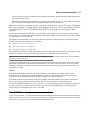
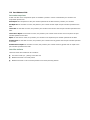
Navigating through the system configuration screens
To help you find your way to particular screens, some sections in this guide begin with a graphical path guide
similar to the following example:
Main
Menu
System
Configuration
IP Setup
This particular path guide shows how to get to the Network Protocols Setup screens. The path guide represents
these steps:
1.
Beginning in the Main Menu, select System Configuration and press Return. The System Configuration
screen appears.
2.
Select IP Setup and press Return. The IP Setup screen appears.
To go back in this sequence of screens, use the Escape key.
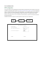
WAN and System Configuration 7-15
System configuration features
The Netopia 4541/4542 ADSL Router’s default settings may be all you need to configure your Netopia
4541/4542. Some users, however, require advanced settings or prefer manual control over the default
selections. For these users, the Netopia 4541/4542 provides system configuration options.
To help you determine whether you need to use the system configuration options, review the following
requirements. If you have one or more of these needs, use the system configuration options described in later
chapters.
■
System configuration of dynamic IP address distribution through DHCP or BootP
■
Greater network security through the use of filters
■
Use of Network Time Protocol
To access the system configuration screens, select System Configuration in the Main Menu, then press
Return.
The System Configuration menu screen appears:
System Configuration
IP Setup...
Filter Sets (Firewalls)...
IP Address Serving...
Date and Time...
Console Configuration...
SNMP (Simple Network Management Protocol)...
Security...
Upgrade Feature Set...
Logging...
Return/Enter to configure Networking Protocols (such as TCP/IP).
Use this screen if you want options beyond Easy Setup.
7-16 User’s Reference Guide
IP setup
These screens allow you to configure your network’s use of the IP networking protocol.
■
Details are given in “IP Setup” on page 8-2.
Filter sets (firewalls)
These screens allow you to configure security on your network by means of filter sets and a basic firewall.
■
Details are given in “Security” on page 11-1.
IP address serving
These screens allow you to configure IP address serving on your network by means of DHCP, WANIP, and BootP.
■
Details are given in “IP Address Serving” on page 8-10.
Date and time
You can set the system’s date and time parameters in the Set Date and Time screen.
Select Date and Time in the System Configuration screen and press Return. The Set Date and Time screen
appears.
Set Date and Time
NTP (Network Time Prot.) Enabled:
Time Server Host Name/IP Address
Time Zone...
NTP Update Interval (HHHH:MM)
On
204.152.184.72
GMT -8:00 Pacific Standard Time
0:00
System Date Format:
MM/DD/YY
System Time Format:
AM/PM
Follow these steps to set the system’s date and time:
1.
Toggle NTP (Network Time Prot.) Enabled to On to synchronize the Router’s time and date with a network
server. Toggle this field to Off to manually set the time and date; the options in this screen will change to
allow you to manually enter the time and date parameters.
Note: If time and date are manually set, that information will be lost upon reboot or loss of power.
2.
Enter the IP address of the time server in the field Time Server Host Name/IP Address.
WAN and System Configuration 7-17
3.
Select the Router’s time zone from the Time Zone pop-up menu and press Return.
4.
In the NTP Update Interval field, enter how often to synchronize with the time server, using the format
HHHH:MM where H is hours and M is minutes.
5.
Select a System Date Format; the options are MM/DD/YY, DD/MM/YY, and YY/MM/DD, where M is
month, D is day, and Y is year.
6.
Select a System Time Format, either AM/PM or 24hrs.
7.
Press Escape to return to the System Configuration menu.
Console configuration
You can change the default terminal communications parameters to suit your requirements.
To go to the Console Configuration screen, select Console Configuration in the System Configuration screen.
Console Configuration
Baud Rate...
57600
SET CONFIG NOW
CANCEL
Follow these steps to change a parameter’s value:
1.
Select 57600, 38400, 19200, or 9600.
2.
Select SET CONFIG NOW to save the new parameter settings. Select CANCEL to leave the parameter
unchanged and exit the Console Configuration screen.
SNMP (Simple Network Management Protocol)
These screens allow you to monitor and configure your network by means of a standard Simple Network
Management Protocol (SNMP) agent.
■
Details are given in “SNMP” on page 12-9.
7-18 User’s Reference Guide
Security
These screens allow you to add users and define passwords on your network.
■
Details are given in “Security” on page 11-1.
Upgrade feature set
You can upgrade your Netopia 4541/4542 by adding new feature sets through the Upgrade Feature Set utility.
See the release notes that came with your router or feature set upgrade, or visit the Netopia Web site at
www.netopia.com for information on new feature sets, how to obtain them, and how to install them on your
Netopia 4541/4542.
Logging
You can configure a UNIX-compatible syslog client to report a number of subsets of the events entered in the
router’s WAN Event History. See “WAN Event History” on page 12-5.
The Syslog client (for the PC only) is available on the Netopia CD.
Select Logging from the System Configuration menu.
The Logging Configuration screen appears.
Logging Configuration
WAN
Log
Log
Log
Log
Log
Event Log Options
Boot and Errors:
Line Specific:
Connections:
PPP, DHCP, CNA:
IP:
Syslog Parameters
Syslog Enabled:
Hostname or IP Address:
Facility...
Yes
Yes
Yes
Yes
Yes
No
Local 0
By default, all events are logged in the event history.
■
By toggling each event descriptor to either Yes or No, you can determine which ones are logged and which
are ignored.
■
You can enable or disable the syslog client dynamically. When enabled, it will report any appropriate and
previously unreported events.
■
You can specify the syslog server’s address either in dotted decimal format or as a DNS name up to 63
characters.
WAN and System Configuration 7-19
■
You can specify the UNIX syslog Facility to use by selecting the Facility pop-up.
■
Erase the log by selecting DUMP WAN LOG
Installing the Syslog client
The Goodies folder on the Netopia CD contains a Syslog client daemon program that can be configured to
report the WAN events you specified in the Logging Configuration screen.
To install the Syslog client daemon, exit from the graphical Netopia CD program and locate the CD directory
structure through your Windows desktop or through Windows Explorer. Go to the Goodies directory on the CD
and locate the Sds15000.exe program. This is the Syslog daemon installer. Run the Sds15000.exe program
and follow the on-screen instructions for enabling the Windows Syslog daemon.
The following screen shows a sample syslog dump of WAN events:
May 5 10:14:06 tsnext.netopia.com
Link 1 down: PPP PAP failure
May 5 10:14:06 tsnext.netopia.com >>Issued Speech Setup Request from our DN: 5108645534
May 5 10:14:06 tsnext.netopia.com
Requested Disc. from DN: 917143652500
May 5 10:14:06 tsnext.netopia.com
Received Clear Confirm for our DN: 5108645534
May 5 10:14:06 tsnext.netopia.com
Link 1 down: Manual disconnect
May 5 10:14:06 tsnext.netopia.com >>Issued Speech Setup Request from our DN: 5108645534
May 5 10:14:06 tsnext.netopia.com
Requested Disc. from DN: 917143652500
May 5 10:14:06 tsnext.netopia.com
Received Clear Confirm for our DN: 5108645534
May 5 10:14:06 tsnext.netopia.com
Link 1 down: No answer
May 5 10:14:06 tsnext.netopia.com --Device restarted----------------------------------------May 5 10:14:06 tsnext.netopia.com >>Received Speech Setup Ind. from DN: (not supplied)
May 5 10:14:06 tsnext.netopia.com
Requested Connect to our DN: 5108645534
May 5 10:14:06 tsnext.netopia.com ASYNC: Modem carrier detected (more) Modem reports: 26400
V34
May 5 10:14:06 tsnext.netopia.com >>WAN: 56K Modem 1 activated at 115 Kbps
May 5 10:14:06 tsnext.netopia.com
Connect Confirmed to our DN: 5108645534
May 5 10:14:06 tsnext.netopia.com
PPP: Channel 1 up, Answer Profile name: Default Profile
May 5 10:14:06 tsnext.netopia.com
PPP: NCP up, session 1, Channel 1 Final (fallback)
negotiated auth: Local PAP , Remote NONE
May 5 10:14:06 tsnext.netopia.com PPP: PAP we accepted remote, Channel 1 Remote name: guest
May
5 10:14:06 tsnext.netopia.com
PPP: MP negotiated, session 1 Remote EDO: 06 03
0000C5700624 0
May 5 10:14:06 tsnext.netopia.com
PPP: CCP negotiated, session 1, type: Ascend LZS Local
mode: 1, Remote mode: 1
May 5 10:14:06 tsnext.netopia.com PPP: BACP negotiated, session 1 Local MN: FFFFFFFF, Remote
MN: 00000001
May 5 10:14:06 tsnext.netopia.com PPP: IPCP negotiated, session 1, rem: 192.168.10.100 local:
192.168.1.1
May 5 10:14:06 tsnext.netopia.com >>WAN: 56K Modem 1 deactivated
May 5 10:14:06 tsnext.netopia.com
Received Clear Ind. from DN: 5108645534, Cause: 0
May 5 10:14:06 tsnext.netopia.com
Issued Clear Response to DN: 5108645534
May 5 10:14:06 tsnext.netopia.com
Link 1 down: Remote clearing
May 5 10:14:06 tsnext.netopia.com
PPP: IPCP down, session 1
May 5 10:14:06 tsnext.netopia.com >>Received Speech Setup Ind. from DN: (not supplied)
7-20 User’s Reference Guide
IP Setup 8-1
Chapter 8
IP Setup
The Netopia 4541/4542 uses Internet Protocol (IP) to communicate both locally and with remote networks.
This chapter shows you how to configure the router to route IP traffic. You also learn how to configure the router
to serve IP addresses to hosts on your local network.
Netopia’s IP routing features Network Address Translation and IP address serving.
This section covers the following topics:
■
“IP Setup” on page 8-2
■
“IP Address Serving” on page 8-10
■
“More Address Serving Options” on page 8-17
■
“DHCP Relay Agent” on page 8-23
■
“Connection Profiles” on page 8-25
Network Address Translation allows communication between the LAN connected to the Netopia 4541/4542
and the Internet using a single (or a few) IP address(es) instead of a routed account with separate IP addresses
for each computer on the network.
Network Address Translation also provides increased security by hiding the local IP addresses of the LAN
connected to the Netopia 4541/4542 from the outside world.
The setup is simpler, so ISPs typically offer Internet accounts supporting Network Address Translation at a
significant cost savings.
For a detailed discussion of Network Address Translation, see Chapter 9, “Multiple Network Address
Translation.”
8-2 User’s Reference Guide
IP Setup
Main
Menu
System
Configuration
IP Setup
The IP Setup options screen is where you configure the Ethernet side of the Netopia 4541/4542. The
information you enter here controls how the router routes IP traffic.
Consult your network administrator or ISP to obtain the IP setup information (such as the Ethernet IP address,
Ethernet subnet mask, default IP gateway, and Primary Domain Name Server IP address) you will need before
changing any of the settings in this screen. Changes to these settings that you make in this screen will take
effect only after the Netopia 4541/4542 is reset.
To go to the IP Setup options screen, from the Main Menu, select System Configuration, then IP Setup.
The IP Setup screen appears.
IP Setup
Ethernet IP Address:
Ethernet Subnet Mask:
Define Additional Subnets...
192.128.117.162
255.255.255.0
Default IP Gateway:
192.128.117.163
Primary Domain Name Server:
Secondary Domain Name Server:
Domain Name:
0.0.0.0
0.0.0.0
yourdomain.com
Receive RIP...
Transmit RIP...
Both
Off
Static Routes...
Network Address Translation (NAT)...
IP Address Serving...
Follow these steps to configure IP setup for your Netopia 4541/4542:
■
Select Ethernet IP Address and enter the IP address for the Netopia 4541/4542’s Ethernet port.
■
Select Ethernet Subnet Mask and enter the subnet mask for the Ethernet IP address that you entered in
the last step.
■
If you desire multiple subnets select Define Additional Subnets. If you select this item you will be taken to
the IP Subnets screen. This screen allows you to define IP addresses and masks for additional subnets.
See “IP subnets” on page 8-4 for details.
IP Setup 8-3
The Netopia 4541/4542 supports multiple IP subnets on the Ethernet interface. You may want to
configure multiple IP subnets to service more hosts than are possible with your primary subnet. It is not
always possible to obtain a larger subnet from your ISP. For example, if you already have a full Class C
subnet, your only option is multiple Class C subnets, since it is virtually impossible to justify a Class A or
Class B assignment.
If you are using NAT, you can use the reserved Class A or Class B subnet.
■
Select Default IP Gateway and enter the IP address for a default gateway. This can be the address of any
major router accessible to the Netopia 4541/4542.
A default gateway should be able to successfully route packets when the Netopia 4541/4542 doesn’t
know how to route to the intended recipient’s IP address. Typically, a default gateway is the ISP’s router.
■
Select Primary Domain Name Server and enter the IP address for a domain name server. The domain
name server matches the alphabetic addresses favored by people (for example, robin.hood.com) to the IP
addresses actually used by IP routers (for example, 163.7.8.202).
■
If a secondary DNS server is available, select Secondary Domain Name Server and enter its IP address.
The secondary DNS server is used by the Netopia 4541/4542 when the primary DNS server is
inaccessible. Entering a secondary DNS is useful but not necessary.
■
Select Domain Name and enter your network’s domain name (for example, netopia.com). Netopia strongly
recommends that you enter a domain name.
■
Routing Information Protocol (RIP) is needed if there are IP routers on other segments of your Ethernet
network that the Netopia 4541/4542 needs to recognize. If this is the case select Receive RIP and select
v1, v2, or Both from the pop-up menu. With Receive RIP set to v1, the Netopia 4541/4542’s Ethernet port
will accept routing information provided by RIP packets from other routers that use the same subnet mask.
Set to v2, the Netopia 4541/4542 will accept routing information provided by RIP packets from other
routers that use different subnet masks. Set to Both, the Netopia 4541/4542 will accept information from
either RIP v1 or v2 routers.
■
If you want the Netopia 4541/4542 to advertise its routing table to other routers via RIP, select Transmit
RIP and select v1, v2 (broadcast), or v2 (multicast) from the pop-up menu. With Transmit RIP v1 selected,
the Netopia 4541/4542 will generate RIP packets only to other RIP v1 routers. With Transmit RIP v2
(broadcast) selected, the Netopia 4541/4542 will generate RIP packets to all other hosts on the network.
With Transmit RIP v2 (multicast) selected, the Netopia 4541/4542 will generate RIP packets only to other
routers capable of recognizing RIP v2 packets.
■
Select Static Routes to manually configure IP routes. See the section “Static routes,” below.
■
Select Network Address Translation to configure advanced MultiNAT features. See Chapter 9, “Multiple
Network Address Translation.”.
■
If you select IP Address Serving you will be taken to the IP Address Serving screen (see “IP Address
Serving” on page 8-10). Since no two hosts can use the same IP address at the same time, make sure
that the addresses distributed by the Netopia 4541/4542 and those that are manually configured are not
the same. Each method of distribution must have its own exclusive range of addresses to draw from.
8-4 User’s Reference Guide
IP subnets
The IP Subnets screen allows you to configure up to eight Ethernet IP subnets on unlimited-user models, one
“primary” subnet and up to seven secondary subnets, by entering IP address/subnet mask pairs:
IP Subnets
#1:
IP Address
---------------192.128.117.162
Subnet Mask
--------------255.255.255.0
#2:
0.0.0.0
0.0.0.0
#3:
#4:
#5:
#6:
#7:
#8:
Note: You need not use this screen if you have only a single Ethernet IP subnet. In that case, you can continue
to enter or edit the IP address and subnet mask for the single subnet on the IP Setup screen.
This screen displays up to eight rows of two editable columns, preceded by a row number between one and
eight. If you have eight subnets configured, there will be eight rows on this screen. Otherwise, there will be one
more row than the number of configured subnets. The last row will have the value 0.0.0.0 in both the IP
address and subnet mask fields to indicate that you can edit the values in this row to configure an additional
subnet. All eight row labels are always visible, regardless of the number of subnets configured.
■
To add an IP subnet, enter the Netopia 4541/4542’s IP address on the subnet in the IP Address field in a
particular row and the subnet mask for the subnet in the Subnet Mask field in that row.
IP Setup 8-5
For example:
IP Subnets
#1:
IP Address
---------------192.128.117.162
Subnet Mask
--------------255.255.255.0
#2:
192.128.152.162
255.255.0.0
#3:
0.0.0.0
0.0.0.0
#4:
#5:
#6:
#7:
#8:
■
To delete a configured subnet, set both the IP address and subnet mask values to 0.0.0.0, either explicitly
or by clearing each field and pressing Return to commit the change. When a configured subnet is deleted,
the values in subsequent rows adjust up to fill the vacant fields.
The subnets configured on this screen are tied to the address serving pools configured on the IP Address Pools
screen, and that changes on this screen may affect the IP Address Pools screen. In particular, deleting a
subnet configured on this screen will delete the corresponding address serving pool, if any, on the IP Address
Pools screen.
8-6 User’s Reference Guide
If you have configured multiple Ethernet IP subnets, the IP Setup screen changes slightly:
IP Setup
Subnet Configuration...
Default IP Gateway:
192.128.117.163
Primary Domain Name Server:
Secondary Domain Name Server:
Domain Name:
0.0.0.0
0.0.0.0
Receive RIP...
Transmit RIP...
Both
v2 (multicast)
Static Routes...
Network Address Translation (NAT)...
IP Address Serving...
Set up the basic IP attributes of your Netopia in this screen.
The IP address and Subnet mask items are hidden, and the Define Additional Subnets... item becomes Subnet
Configuration.... If you select Subnet Configuration, you will return to the IP Subnets screen that allows you to
define IP addresses and masks for additional Ethernet IP subnets.
Static routes
Static routes are IP routes that are maintained manually. Each static route acts as a pointer that tells the
Netopia 4541/4542 how to reach a particular network. However, static routes are used only if they appear in
the IP routing table, which contains all of the routes used by the Netopia 4541/4542 (see “IP Routing Table” on
page 12-7).
Static routes are helpful in situations where a route to a network must be used and other means of finding the
route are unavailable. For example, static routes are useful when you cannot rely on RIP.
To go to the Static Routes screen, select Static Routes in the IP Setup screen and press Return.
IP Setup 8-7
The Static Routes screen will appear.
Static Routes
Display/Change Static Route...
Add Static Route...
Delete Static Route...
Configure/View/Delete Static Routes from this and the following Screens.
Viewing static routes
To display a view-only table of static routes, select Display/Change Static Route. The table shown below will
appear.
+-Dest. Network---Subnet Mask-----Next Gateway----Priority-Enabled-+
+------------------------------------------------------------------+
| 0.0.0.0
0.0.0.0
163.176.8.1
Low
Yes
|
|
|
|
|
|
|
|
|
|
|
|
|
|
|
|
|
|
|
|
|
|
|
|
|
|
|
|
|
+------------------------------------------------------------------+
Select a Static Route to modify.
The table has the following columns:
Dest. Network: The network IP address of the destination network.
8-8 User’s Reference Guide
Subnet Mask: The subnet mask associated with the destination network.
Next Gateway: The IP address of the router that will be used to reach the destination network.
Priority: An indication of whether the Netopia 4541/4542 will use the static route when it conflicts with
information received from RIP packets.
Enabled: An indication of whether the static route should be installed in the IP routing table.
To return to the Static Routes screen, press Escape.
Adding a static route
To add a new static route, select Add Static Route in the Static Routes screen. The Add Static Route screen
will appear.
Add Static Route
Static Route Enabled:
Yes
Destination Network IP Address:
0.0.0.0
Destination Network Subnet Mask:
0.0.0.0
Next Gateway IP Address:
0.0.0.0
Route Priority...
High
Advertise Route Via RIP:
No
ADD STATIC ROUTE NOW
CANCEL
Configure a new Static Route in this Screen.
■
To install the static route in the IP routing table, select Static Route Enabled and toggle it to Yes. To
remove the static route from the IP routing table, select Static Route Enabled and toggle it to No.
■
Be sure to read the rules on the installation of static routes in the IP routing table. See “Rules of static
route installation” on page 8-9.
■
Select Destination Network IP Address and enter the network IP address of the destination network.
■
Select Destination Network Subnet Mask and enter the subnet mask used by the destination network.
■
Select Next Gateway IP Address and enter the IP address for the router that the Netopia 4541/4542 will
use to reach the destination network. This router does not necessarily have to be part of the destination
network, but it must at least know where to forward packets destined for that network.
■
Select Route Priority and choose High or Low. High means that the static route takes precedence over RIP
IP Setup 8-9
information; Low means that the RIP information takes precedence over the static route.
■
If the static route conflicts with a connection profile, the connection profile will always take precedence.
■
To make sure that the static route is known only to the Netopia 4541/4542, select Advertise Route Via
RIP and toggle it to No. To allow other RIP-capable routers to know about the static route, select Advertise
Route Via RIP and toggle it to Yes. When Advertise Route Via RIP is toggled to Yes, a new item called RIP
Metric appears below Advertise Route Via RIP.
With RIP Metric you set the number of routers, from 1 to 15, between the sending router and the
destination router. The maximum number of routers on a packet’s route is 15. Setting RIP Metric to 1
means that a route can involve 15 routers, while setting it to 15 means a route can only involve one router.
■
Select ADD STATIC ROUTE NOW to save the new static route, or select CANCEL to discard it and return to
the Static Routes screen.
■
Up to 32 static routes can be created, but one is always reserved for the default gateway, which is
configured using either Easy Setup or the IP Setup screen in system configuration.
Modifying a static route
To modify a static route, in the Static Routes screen select Display/Change Static Route to display a table of
static routes.
Select a static route from the table and go to the Change Static Route screen. The parameters in this screen
are the same as the ones in the Add Static Route screen (see “Adding a static route” on page 8-8).
Deleting a static route
To delete a static route, in the Static Routes screen select Delete Static Route to display a table of static
routes. Select a static route from the table and press Return to delete it. To exit the table without deleting the
selected static route, press Escape.
Rules of static route installation
The Netopia 4541/4542 applies certain rules before installing enabled static routes in the IP routing table. An
enabled static route will not be installed in the IP routing table if any of the following conditions are true:
■
The static route’s Next Gateway IP Address matches an IP address in the range of IP addresses being
distributed by DHCP.
■
The static route’s Next Gateway IP Address is determined to be unreachable by the Netopia 4541/4542.
■
The static route’s route information conflicts with a connection profile’s route information.
■
The connection profile associated with the static route has a disabled dial-on-demand setting, and there is
no current connection using that connection profile.
A static route that is already installed in the IP routing table will be removed if any of the conditions listed above
become true for that static route. However, an enabled static route is automatically reinstalled once the
conditions listed above are no longer true for that static route.
8-10 User’s Reference Guide
IP Address Serving
Main
Menu
System
Configuration
IP Address
Serving
• Serve DHCP Clients
• Serve BootP Clients
• Serve Dynamic WAN Clients
In addition to being a router, the Netopia 4541/4542 is also an IP address server. There are three protocols it
can use to distribute IP addresses.
■
The first, called Dynamic Host Configuration Protocol (DHCP), is widely supported on PC networks, as well
as Apple Macintosh computers using Open Transport and computers using the UNIX operating system.
Addresses assigned via DHCP are “leased” or allocated for a short period of time; if a lease is not
renewed, the address becomes available for use by another computer. DHCP also allows most of the IP
parameters for a computer to be configured by the DHCP server, simplifying setup of each machine.
■
The second, called BootP (also known as Bootstrap Protocol), is the predecessor to DHCP and allows older
IP hosts to obtain most of the information that a DHCP client would obtain. However, in contrast, BootP
address assignments are “permanent” since there is no lease renewal mechanism in BootP.
■
The third protocol, called Dynamic WAN, is part of the PPP/MP suite of wide area protocols used for WAN
connections. It allows remote terminal adapters and NAT-enabled routers to be assigned a temporary IP
address for the duration of their connection.
Since no two hosts can use the same IP address at the same time, make sure that the addresses distributed
by the Netopia 4541/4542 and those that are manually configured are not the same. Each method of
distribution must have its own exclusive range of addresses to draw from.
Go to the System Configuration screen. Select IP Address Serving and press Return. The IP Address Serving
screen will appear.
IP Address Serving
+--------------------+
+--------------------+
IP Address Serving Mode...
| Disabled
|
| DHCP Server
|
Number of Client IP Addresses:
| DHCP Relay Agent
|
1st Client Address:
+--------------------+
Client Default Gateway...
192.168.1.1
Serve DHCP Clients:
DHCP Lease Time (Hours):
DHCP NetBIOS Options...
Yes
1
Serve BOOTP Clients:
Yes
Serve Dynamic WAN Clients
Yes
IP Setup 8-11
Follow these steps to configure IP Address Serving:
■
If you enabled IP Address Serving, then DHCP, BootP clients and Dynamic WAN clients are automatically
enabled.
■
The IP Address Serving Mode pop-up menu allows you to choose the way in which the Netopia 4541/4542
will serve IP addresses. The device can act as either a DHCP Server or a DHCP Relay Agent. (See “DHCP
Relay Agent” on page 8-23 for more information.) In most cases, you will use the device to serve its own
pool of IP addresses, hence DHCP Server is the default. Address serving can also be disabled.
■
Select Number of Client IP Addresses and enter the total number of contiguous IP addresses that the
Netopia 4541/4542 will distribute to the client machines on your local area network. Twelve-user models
are limited to twelve IP addresses.
In the screen example shown above, five Client IP addresses have been allocated.
■
Select 1st Client Address and enter the first client IP address that you will allocate to your first client
machine. For instance, on your local area network you may want to first figure out which machines are going
to be allocated specific static IP addresses so that you can determine the pool of IP addresses that you will
be serving addresses from via DHCP, BootP, and/or Dynamic WAN.
Example: Your ISP has given your Netopia 4541/4542 the IP address 192.168.6.137, with a subnet mask
of 255.255.255.248. The subnet mask allocated will give you six IP addresses to use when connecting to
the ISP over the Internet. Your address range will be from .137-.143. In this example you would enter
192.168.6.138 as the 1st Client Address, since the router itself must have an IP address.
■
To enable DHCP, select Serve DHCP Clients and toggle it to Yes. DHCP serving is automatic when IP
Address Serving is enabled.
■
The default DHCP Lease time is one hour. This may be unnecessarily brief in your network environment.
Consequently, the DHCP lease time is now configurable. The DHCP Lease Time (Hours) setting allows you
to modify the router’s default lease time of one hour. You can enter any number up to and including 168
hours (one week) for the DHCP lease.
8-12 User’s Reference Guide
If you have configured multiple Ethernet IP subnets, the appearance of the IP Address Serving screen is altered
slightly:
IP Address Serving
IP Address Serving Mode...
DHCP Server
Configure Address Pools...
Serve DHCP Clients:
DHCP Lease Time (Hours):
DHCP NetBIOS Options...
Yes
1
Serve BOOTP Clients:
Yes
Serve Dynamic WAN Clients
Yes
Three menu items are hidden, and Configure Address Pools... appears instead. If you select Configure
Address Pools... you will be taken to the IP Address Pools screen that allows you to configure an address
serving pool for each of the configured Ethernet IP subnets. See “IP Address Pools” on page 8-13.
IP Setup 8-13
IP Address Pools
The IP Address Pools screen allows you to configure a separate IP address serving pool for each of up to eight
configured Ethernet IP subnets:
IP Address Pools
Subnet (# host addrs)
--------------------192.128.117.0
(253)
1st Client Addr
--------------192.128.117.196
Clients
------16
Client Gateway
-------------192.128.117.162
192.129.117.0
192.129.117.110
8
192.129.117.4
(253)
This screen consists of between two and eight rows of four columns each. There are exactly as many rows as
there are Ethernet IP subnets configured on the IP Subnets screen.
■
The Subnet (# host addrs) column is non-selectable and non-editable. It indicates the network address of
the Ethernet IP subnet for which an address pool is being configured and the number of host addresses
available on the subnet. The network address is equal to the router’s IP address on the subnet
bitwise-ANDed with the subnet mask. The host address count is equal to the subnet size minus three,
since one address is reserved for the network address, one for the subnet broadcast address, and one for
the router’s interface address on the subnet.
You can edit the remaining columns in each row.
■
The 1st Client Addr and Clients columns allow you to specify the base and extent of the address serving
pool for a particular subnet. Entering 0.0.0.0 for the first client address or 0 for the number of clients
indicates that no addresses will be served from the corresponding Ethernet IP subnet.
■
The Client Gateway column allows you to specify the default gateway address that will be provided to
clients served an address from the corresponding pool. The value defaults to the Netopia 4541/4542’s IP
address on the corresponding subnet (or the Netopia 4541/4542’s default gateway, if that gateway is
located on the subnet in question). You can override the value by entering any address that is part of the
subnet.
DHCP, BootP, and dynamic WAN clients may receive an address from any one of the address serving pools
configured on this screen.
8-14 User’s Reference Guide
Numerous factors influence the choice of served address. It is difficult to specify the address that will be
served to a particular client in all circumstances. However, when the address server has been configured, and
the clients involved have no prior address serving interactions, the Netopia 4541/4542 will generally serve the
first unused address from the first address pool with an available address. The Netopia 4541/4542 starts
from the pool on the first row and continues to the pool on the last row of this screen.
Once the address server and/or the clients have participated in address serving transactions, different rules
apply:
■
When requesting an address, a client will often suggest an address to be assigned, such as the one it was
last served. The Netopia 4541/4542 will attempt to honor this request if the address is available. The
client stores this address in non-volatile storage, for example, on disk, and the specific storage
method/location differs depending on the client operating system.
■
When requesting an address, a client may provide a client identifier, or, if it does not, the Netopia
4541/4542 may construct a pseudo-client identifier for the client. When the client subsequently requests
an address, the Netopia 4541/4542 will attempt to serve the address previously associated with the
pseudo-client identifier. This is normally the last address served to the client.
■
Otherwise, the Netopia will select the least-recently used available address, starting from the first address
in the first pool and ending with the last address in the last pool.
Note: The address serving pools on this screen are tied to the IP subnets configured on the IP Subnets screen.
Changes to the IP Subnets screen may affect this screen. In particular, deleting a subnet on the IP Subnets
screen will delete the corresponding address serving pool, if any, on this screen.
IP Setup 8-15
DHCP NetBIOS Options
If your network uses NetBIOS, you can enable the Netopia 4541/4542 to use DHCP to distribute NetBIOS
information.
NetBIOS stands for Network Basic Input/Output System. It is a layer of software originally developed by IBM
and Sytek to link a network operating system with specific hardware. NetBIOS has been adopted as an industry
standard. It offers LAN applications a variety of “hooks” to carry out inter-application communications and data
transfer. Essentially, NetBIOS is a way for application programs to talk to the network. To run an application that
works with NetBIOS, a non-IBM network operating system or network interface card must offer a NetBIOS
emulator. Many vendors either provide a version of NetBIOS to interface with their hardware or emulate its
transport layer communications services in their network products. A NetBIOS emulator is a program provided
by NetWare clients that allow workstations to run applications that support IBM’s NetBIOS calls.
■
Select DHCP NetBios Options and press Return. The DHCP NetBIOS Options screen appears.
DHCP NetBios Options
Serve NetBios Type:
NetBios Type...
Yes
Type B
Serve NetBios Scope:
NetBios Scope:
No
Serve NetBios Name Server:
NetBios Name Server IP Addr:
No
0.0.0.0
Configure DHCP-served NetBIOS options here.
■
To serve DHCP clients with the type of NetBIOS used on your network, select Serve NetBios Type and
toggle it to Yes.
8-16 User’s Reference Guide
■
From the NetBios Type pop-up menu, select the type of NetBIOS used on your network.
DHCP NetBios Options
Serve NetBios Type:
NetBios Type...
Serve NetBios Scope:
NetBios Scope:
Serve NetBios Name Server:
NetBios Name Server IP Addr:
■
+--------+
+--------+
| Type B |
| Type P |
| Type M |
| Type H |
+--------+
No
0.0.0.0
To serve DHCP clients with the NetBIOS scope, select Serve NetBios Scope and toggle it to Yes.
Select NetBios Scope and enter the scope.
■
To serve DHCP clients with the IP address of a NetBIOS name server, select Serve NetBIOS Name Server
and toggle it to Yes.
Select NetBios Name Server IP Addr and enter the IP address for the NetBIOS name server.
You are now finished setting up DHCP NetBIOS Options. To return to the IP Address Serving screen, press
Escape.
■
To enable BootP’s address serving capability, select Serve BOOTP Clients and toggle to Yes.
Note: Addresses assigned through BootP are permanently allocated from the IP Address Serving pool until
you release them. To release these addresses, navigate back to the Main Menu, then Statistics & Logs,
Served IP Addresses, and Lease Management.
Main
Menu
Statistics
& Logs
Served IP
Addresses
Lease Management
IP Setup 8-17
IP Address Lease Management
Reset All Leases
Release BootP Leases
Reclaim Declined Addresses
Hit RETURN/ENTER, you will return to the previous screen.
Select Release BootP Leases and press Return.
■
Back in IP Address Serving, the Serve Dynamic WAN Clients toggle
More Address Serving Options
The Netopia 4541/4542 includes a number of enhancements in the built-in DHCP IP address server. These
enhancements include:
■
The ability to exclude one or more IP addresses from the address serving pool so the addresses will not be
served to clients.
■
The ability to reserve a particular IP address for a client with a particular Ethernet MAC address.
■
The ability to view the host name associated with a client to which the router has leased an IP address.
■
The ability for the router’s Ethernet IP address(es) to overlap the DHCP address serving pool(s).
■
The ability to serve as a DHCP Relay Agent.
The Netopia 4541/4542 supports reserving an IP address only for a type 1 client identifier (i.e., an Ethernet
hardware address). It does not support reserving an IP address for an arbitrary client identifier. (For more
information on client identifiers, see RFC 2131, section 9.14.)
8-18 User’s Reference Guide
Configuring the IP Address Server options
To access the enhanced DHCP server functions, from the Main Menu navigate to Statistics & Logs and then
Served IP Addresses.
Main
Menu
Statistics & Logs
Served IP
Addresses
The following example shows the Served IP Addresses screen after three clients have leased IP addresses. The
first client did not provide a Host Name in its DHCP messages; the second and third clients did.
Served IP Addresses
-IP Address------Type----Expires—-Host Name/Client Identifier--------------------------------------------------SCROLL UP----------------------------------192.168.1.100
192.168.1.101
192.168.1.102
192.168.1.103
DHCP
00:59
EN: 00-00-C5-70-00-04
192.168.1.104
DHCP
00:59
Bill’s Pentium
192.168.1.105
DHCP
00:45
Steve’s Power Mac
192.168.1.106
192.168.1.107
192.168.1.108
192.168.1.109
192.168.1.110
192.168.1.111
192.168.1.112
192.168.1.113
---------------------------------SCROLL DOWN---------------------------------Lease Management...
The rightmost column displays the host name supplied by the client if one was provided; otherwise it displays
the client identifier. (If a host name is displayed, the client identifier is still accessible in a Details pop-up menu.
See below.)
Note: The server does not query the client for its host name. Macintosh computers running versions of MacOS
prior to MacOS version 8.5 (OT 2.0.1, TCP/IP 2.0.1) do not supply a host name option in their DHCP messages,
so no host name will appear in the Served IP Addresses list.
IP Setup 8-19
You can select the entries in the Served IP Addresses screen. Use the up and down arrow keys to move the
selection to one of the entries in the list of served IP addresses.
Served IP Addresses
-IP Address------Type----Expires—-Host Name/Client Identifier--------------------------------------------------SCROLL UP----------------------------------192.168.1.100
192.168.1.101
192.168.1.102
192.168.1.103
192.168.1.104
192.168.1.105
192.168.1.106
+------------+
192.168.1.107
+------------+
192.168.1.108
| Details... |
Barr's XPi 120
192.168.1.109
| Exclude
|
192.168.1.110
| Release
|
192.168.1.111
| Reserve... |
192.168.1.112
+------------+
192.168.1.113
---------------------------------SCROLL DOWN---------------------------------Lease Management...
Once you select an entry, pressing Return displays an action pop-up menu that lists operations that can be
performed on that entry. Possible operations are Details…, Exclude, Include, Release, and Reserve… The
action popup is context-sensitive and lists only those operations that apply to the selected IP address in its
current lease state.
8-20 User’s Reference Guide
■
Details… is displayed if the entry is associated with both a host name and a client identifier.
Selecting Details… displays a pop-up menu that provides additional information associated with the IP
address. The pop-up menu includes the IP address as well as the host name and client identifier supplied
by the client to which the address is leased.
Served IP Addresses
-IP Address------Type----Expires—-Host Name/Client Identifier--------------------------------------------------SCROLL UP----------------------------------192.168.1.100
192.168.1.101
+----------------------------------------------------------------------------+
+----------------------------------------------------------------------------+
|
|
| IP Address is 192.168.1.108
|
| Host Name is Barr's XPi 120
|
| Client ID is EN: 00-00-c5-45-89-ef
|
|
|
|
OK
|
+----------------------------------------------------------------------------+
192.168.1.111
| Reserve... |
192.168.1.112
+------------+
192.168.1.113
---------------------------------SCROLL DOWN---------------------------------Lease Management...
■
Exclude is displayed if the entry is not already excluded.
Selecting Exclude excludes the IP address from the address serving pool so the address will not be served
to a client. If the IP address is currently leased to or reserved for a client, you will be presented with a
warning dialog asking you to confirm the operation.
IP Setup 8-21
Served IP Addresses
-IP Address------Type----Expires—-Host Name/Client Identifier--------------------------------------------------SCROLL UP----------------------------------192.168.1.100
192.168.1.101
192.1+-------------------------------------------------------------+
192.1+-------------------------------------------------------------+
192.1|
|
192.1| You are about to make changes that will affect an address
|
192.1| that is currently in use. Are you sure you want to do this? |
192.1|
|
192.1|
CANCEL
OK
|
192.1|
|
192.1+-------------------------------------------------------------+
192.168.1.111
| Reserve... |
192.168.1.112
+------------+
192.168.1.113
---------------------------------SCROLL DOWN---------------------------------Lease Management...
■
Include is displayed if the entry is either excluded or declined.
An IP address is marked declined when a client to whom the DHCP server offers the address declines the
address. A client declines an address if it determines that a leased address is already in use by another
device.
Selecting Include restores the selected IP address to the address serving pool so that the IP address is
once again eligible to be served to a client.
■
Release is displayed if the entry is currently offered, leased, or reserved.
Selecting Release puts the selected entry in the available state. You will be presented with a warning
dialog asking you to confirm the operation since the IP address is in use. There is no mechanism to notify
the client to whom the address is leased that the lease has been terminated. Thus, the client will continue
to use the address until the next time it attempts to renew its lease. In the interim, the server may lease
the same IP address to a different client, thereby creating an address conflict. For this reason, releasing
an address that is actively being used by a client is generally not recommended.
■
Reserve… is displayed if the entry is available, declined, excluded, leased, offered, or reserved.
Reserving an IP address for a client with a particular Ethernet MAC address guarantees that a client with
the specified MAC address will be offered or leased the specified IP address. Moreover, it prevents the
specified IP address from being offered or leased to any other client.
Selecting Reserve... displays a pop-up dialog box that displays the IP address and editable item in which
you can enter an Ethernet MAC address. The pop-up dialog box includes OK and CANCEL buttons for
confirming or cancelling the operation. If the IP address is currently offered or leased to, or reserved for, a
client, you will be presented with a warning dialog asking you to confirm the operation. Reserving an IP
address guarantees that the IP address will only be leased.
8-22 User’s Reference Guide
Served IP Addresses
-IP Address------Type----Expires—-Host Name/Client Identifier--------------------------------------------------SCROLL UP----------------------------------192.168.1.100
192.168.1.101
192.168.1.102
+--------------------------------------+
192.168.1.103
+--------------------------------------+
192.168.1.104
|
|
192.168.1.105
| IP Address is 192.168.1.108
|
192.168.1.106
| MAC Address: 00-00-c5-45-89-ef
|
192.168.1.107
|
|
192.168.1.108
|
CANCEL
OK
|
192.168.1.109
|
|
192.168.1.110
|
|
192.168.1.111
+--------------------------------------+
192.168.1.112
+------------+
192.168.1.113
---------------------------------SCROLL DOWN---------------------------------Lease Management...
The router’s Ethernet IP address(es) will be automatically excluded from the address serving pool(s) on startup.
Entries in the served IP address list corresponding to the router’s Ethernet IP address(es) that have been
automatically excluded on startup are not selectable.
Served IP Addresses
-IP Address------Type----Expires--Host Name/Client Identifier--------------------------------------------------SCROLL UP----------------------------------192.168.1.1
Excluded for the router's IP address
192.168.1.2
Excluded
192.168.1.3
DHCP
00:24
Barr's XPi 120
192.168.1.4
192.168.1.5
192.168.1.6
192.168.1.7
192.168.1.8
192.168.1.9
192.168.1.10
192.168.1.11
192.168.1.12
192.168.1.13
192.168.1.14
---------------------------------SCROLL DOWN---------------------------------Lease Management...
Hit RETURN/ENTER for available operations.
IP Setup 8-23
DHCP Relay Agent
The Netopia 4541/4542 offers DHCP Relay Agent functionality, as defined in RFC1542. A DHCP relay agent is
a computer system or a router that is configured to forward DHCP requests from clients on the LAN to a remote
DHCP server, and to pass the replies back to the requesting client systems.
When a DHCP client starts up, it has no IP address, nor does it know the IP address of a DHCP server.
Therefore, it uses an IP broadcast to communicate with one or more DHCP servers. These broadcasts are
normally limited to the network segment on which the client is located, and do not pass through routers such as
the Netopia Router. If the Netopia Router is configured to act as a DHCP server, it will assign the client an
address from an address pool configured locally in the Netopia Router and respond to the client's request
itself.
However, if the Netopia Router is configured to act as a DHCP relay agent, it does not satisfy the DHCP request
itself, but instead forwards the request to one or more remote DHCP servers. These servers process the
request, assign an address from an address pool configured on the remote server, and forward the response
back to the Netopia Router for delivery back to the client. The agent then sends the response to the client on
behalf of the DHCP server. This process is transparent to the client, which doesn't know that it is
communicating through an intermediary rather than directly to a local server. Using DHCP relay, it is possible to
centralize the configuration information for the host computers at many remote sites at a single location, easing
the burden of administering configuration management for remote sites.
To configure the Netopia Router to act as a DHCP relay agent, from the Main Menu navigate to the System
Configuration menu.
Main
Menu
System
Configuration
IP Address
Serving
8-24 User’s Reference Guide
Select IP Address Serving and press Return. The IP Address Serving screen appears.
IP Address Serving
+------------------+
+------------------+
IP Address Serving Mode...
| Disabled
|
| DHCP Server
|
Number of Client IP Addresses:
| DHCP Relay Agent |
1st Client Address:
+------------------+
Client Default Gateway...
192.168.1.1
Serve DHCP Clients:
DHCP NetBIOS Options...
Yes
Serve BOOTP Clients:
Yes
Select IP Address Serving Mode. The pop-up menu offers the choices of Disabled, DHCP Server (the default),
and DHCP Relay Agent.
If you select DHCP Relay Agent and press Return, the screen changes as shown below.
IP Address Serving
IP Address Serving Mode...
DHCP Relay Agent
Relay Server #1:
Relay Server #2:
Relay Server #3:
10.1.1.1
20.1.1.1
30.1.1.1
Configure Address Serving (DHCP, BOOTP, etc.) here.
Now you can enter the IP address(es) of your remote DHCP server(s), such as might be located in your
company’s corporate headquarters. Each time you enter an IP address and press Return, an additional field
appears. You can enter up to four DHCP server addresses.
In the example above, DHCP requests from clients on the LAN will be relayed to the DHCP servers at IP
addresses 10.1.1.1, 20.1.1.1, and 30.1.1.1.
IP Setup 8-25
Note: The remote DHCP server(s) to which the Netopia Router is relaying DHCP requests must be capable of
servicing relayed requests. Not all DHCP servers support this feature. For example, the DHCP server in the
Netopia Router does not.
The DHCP server(s) to which the Netopia Router is relaying DHCP requests must be configured with one or more
address pools that are within the Netopia Router’s primary Ethernet LAN subnet. (There is no mechanism for
DHCP clients to receive an address on a secondary subnet via a relayed DHCP request.)
Connection Profiles
Since you will probably only have a single connection to your ISP over the DSL link, you may not need to create
multiple connection profiles. Additional profiles may be useful for creating VPNs.
Connection Profiles define the line and networking protocols necessary for the router to make a remote
connection. A connection profile is like an address book entry describing how the router is to get to a remote
site, or how to recognize and authenticate a remote user connecting to the router. To create a new Connection
Profile, you navigate to the WAN Configuration screen from the Main Menu, and select Add Connection Profile.
Main
Menu
WAN
Configuration
Add Connection
Profile
The Add Connection Profile screen appears.
Add Connection Profile
Profile Name:
Profile Enabled:
Profile 1
Yes
Data Link Encapsulation...
Data Link Options...
PPP
IP Profile Parameters...
COMMIT
Configure a new Conn. Profile. Finished?
CANCEL
COMMIT or CANCEL to exit.
On a Netopia 4541/4542 you can add up to 15 more connection profiles, for a total of 16, although only one
can be used at a time, unless you are using VPNs.
1.
Select Profile Name and enter a name for this connection profile. It can be any name you wish. For
example: the name of your ISP.
8-26 User’s Reference Guide
2.
Toggle the Profile Enabled value to Yes or No. The default is Yes.
3.
Select IP Profile Parameters and press Return. The IP Profile Parameters screen appears.
IP Profile Parameters
Address Translation Enabled:
IP Addressing...
Yes
Numbered
NAT Map List...
NAT Server List...
Easy-PAT List
Easy-Servers
Local WAN
Local WAN
Remote IP
Remote IP
0.0.0.0
0.0.0.0
0.0.0.0
0.0.0.0
IP Address:
IP Mask:
Address:
Mask:
Filter Set...
Remove Filter Set
RIP Profile Options...
Configure IP requirements for a remote network connection here.
4.
Toggle or enter any IP parameters you require and return to the Add Connection Profile screen by pressing
Escape. For more information on NAT, see “Multiple Network Address Translation,” beginning on page 9-1.
The Local WAN IP Address is displayed for numbered or NAT profiles. The Local WAN IP Mask is displayed
for numbered profiles. The Remote IP Address and Remote IP Mask are displayed for unnumbered profiles.
IP Setup 8-27
5.
Select ADD PROFILE NOW and press Return. Your new connection profile will be added.
If you want to view the connection profiles in your router, return to the WAN Configuration screen, and
select Display/Change Connection Profile. The list of connection profiles is displayed in a scrolling pop-up
screen.
WAN Configuration
+-Profile Name---------------------IP Address------+
+--------------------------------------------------+
| Easy Setup Profile
127.0.0.2
|
| Profile 1
0.0.0.0
|
|
|
|
|
|
|
|
|
|
|
|
|
|
|
|
|
|
|
|
|on:
|
|
|
|
|
|
|
|
+--------------------------------------------------+
Up/Down Arrow Keys to select, ESC to dismiss, Return/Enter to Edit.
Yes
8-28 User’s Reference Guide
Multiple Network Address Translation 9-1
Chapter 9
Multiple Network Address Translation
The Netopia 4541/4542 offers advanced Multiple Network Address Translation functionality.
You should read this chapter completely before attempting to configure any of the advanced NAT features.
This chapter covers the following topics:
■
Overview on page 9-1
■
MultiNAT Configuration on page 9-5
■
Easy Setup Profile configuration on page 9-6
■
Server Lists and Dynamic NAT configuration on page 9-6
■
Adding Server Lists on page 9-14
■
Binding Map Lists and Server Lists on page 9-20
■
NAT Associations on page 9-24
■
MultiNAT Configuration Example on page 9-26
Overview
NAT (Network Address Translation) is a means of mapping one or more IP addresses and/or IP service ports
into different values. This mapping serves two functions:
■
It allows the addresses of many computers on a LAN to be represented to the public Internet by only one or
a few addresses, saving you money.
■
It can be used as a security feature by obscuring the true addresses of important machines from potential
hackers on the Internet.
To help you understand some of the concepts discussed here, it may be helpful to introduce some NAT
terminology.
The term mapping refers to rules that associate one or more private addresses on the Netopia Router’s LAN to
one or more public addresses on the Netopia Routers WAN interface (typically the Internet).
The terms private and internal refer to addresses on the Netopia Router’s LAN. These addresses are
considered private because they are protected or obscured by NAT and cannot be directly accessed from the
WAN (or Internet) side of the Netopia Router unless specifically configured otherwise.
The terms public and external refer to the WAN (or Internet) side of the Netopia Router.
Features
MultiNAT features can be divided into several categories that can be used simultaneously in different
combinations on a per-Connection Profile basis.
9-2 User’s Reference Guide
The following is a general description of these features:
Port Address Translation
The simplest form of classic Network Address Translation is PAT (Port Address Translation). PAT allows a group
of computers on a LAN, such as might be found in a home or small office, to share a single Internet connection
using one IP address. The computers on the LAN can surf the Web, read e-mail, download files, etc., but their
individual IP addresses are never exposed to the public network. Instead, a single IP address acts as the
source IP address of traffic originating from the LAN. The Netopia Router allows you to define multiple PAT
mappings, which can be individually mapped to different public IP addresses. This offers more control over the
access permitted to users on the LAN.
A limitation of PAT is that communication must be initiated from the internal network. A user on the external
side cannot access a machine behind a PAT connection. A PAT enhancement introduced in firmware version 4.4
is the ability to define multiple PAT mappings. Each of these can optionally map to a section or range of IP
addresses of the internal network. PAT mapping allows only internal users to initiate traffic flow between the
internal and external networks.
Server lists
Server lists, previously known as exported services, make it possible to provide access from the public network
to hosts on the LAN. Server lists allow you to define particular services, such as Web, ftp, or e-mail, which are
available via a public IP address. You define the type of service you would like to make available and the
internal IP address to which you would like to provide access. You may also define a specific public IP address
to use for this service if you want to use an IP other than the WAN IP address of the Netopia Router.
Static mapping
If you want to host your own Website or provide other Internet services to the public, you need more than
classic NAT. The reason is noted under Port Address Translation above – external users cannot initiate traffic to
computers on your LAN because external users can never see the real addresses of the computers on your
LAN. If you want users outside your LAN to have access, for example, to a Web or FTP server that you host, you
need to make a public representation of the real IP addresses of those servers.
Static mappings are a way to make one or more private IP addresses fully accessible from the public network
via corresponding public IP addresses. Some applications may negotiate multiple TCP connections in the
process of communication, which often does not work with traditional PAT. Static mapping offers the ability to
use these applications through NAT. Each private IP address is mapped, on a one-to-one basis, to a public IP
address that can be accessed from the Internet or public network. As with PAT mappings, you may have multiple
static mappings to map a range of private IP addresses to a range of public IP addresses if desired.
Dynamic mapping
Dynamic mapping, often referred to as many-to-few, offers an extension to the advantages provided by static
mapping. Instead of requiring a one-to-one association of public addresses and private addresses, as is
required in static mapping, dynamic mapping uses a group of public IP addresses to dynamically allocate static
mappings to private hosts that are communicating with the public network. If a host on the private network
initiates a connection to the Internet, for example, the Netopia Router automatically sets up a one-to-one
mapping of that host’s private IP address to one of the public IP addresses allocated to be used for Dynamic
NAT. As long as this host is communicating with the Internet, it will be able to use that address. When traffic
from that host ceases, and no traffic is passed from that host for five minutes, the public address is made
available again for other private hosts to use as necessary.
Multiple Network Address Translation 9-3
When addresses are returned to the group of available addresses, they are returned to the head of the group,
being the most recently used. If that same host requests a connection an hour later, and the same public
address is still available, then it will be mapped to the same private host. If a new host, which has not
previously requested a connection, initiates a connection it is allocated the last, or oldest, public address
available.
Dynamic NAT is a way of sharing a range of public, or exterior, NAT addresses among one or more groups of
private, or interior, hosts. This is intended to provide superior support for applications that traditionally have
difficulty communicating through NAT. Dynamic NAT is intended to provide functionality beyond many-to-one and
one-to-one translation. Netopia’s NAT implementation makes it possible to have a static mapping of one public
address to one private address, thus allowing applications such as NetMeeting to work by assuring that any
traffic sent back to the source IP address is forwarded through to the internal machine.
Static one-to-one mapping works well if you have enough IP addresses for all the workstations on your LAN. If
you do not, Dynamic NAT allows machines to make full use of the publicly routable IP addresses provided by the
ISP as necessary, on demand. When these public IP addresses are no longer being used by a particular
workstation, they are returned to a pool of available addresses for other workstations to use.
A common example is a DSL customer’s application. Most DSL ISPs only provide customers with a few IP
addresses for use on their network. For networks with more than four or five machines it is usually mandatory to
use NAT. A customer may have 15 workstations on the LAN, all of which need Internet access. The customer is
only provided five IP addresses by their ISP. The customer has eight hosts, which only need to use email and
have Web access, but another seven hosts, which use NetMeeting to communicate with clients once or twice a
day. NetMeeting will not work unless a static one-to-one mapping exists for the machine running NetMeeting to
use for communication. The customer does not have enough IP addresses to create a one-to-one mapping for
each of the seven users. This is where dynamic NAT applies.
The customer can configure four of these addresses to be used for Dynamic NAT. The fifth address is then used
for the eight other machines that do not need one-to-one mappings. As each machine configured to use
addresses from the dynamic pool tries to connect to the Internet it is allocated a public IP address to use
temporarily. Once the communication has been terminated, that IP address is freed for one of the other six
hosts to use.
Available for Dynamic NAT
Used for Normal NAT
172.16.1.29
172.16.1.28
172.16.1.27
172.16.1.26
172.16.1.25
WAN Network
192.168.1.16
192.168.1.15
192.168.1.14
192.168.1.13
192.168.1.12
192.168.1.11
192.168.1.10
192.168.1.9
192.168.1.8
192.168.1.7
192.168.1.6
192.168.1.5
192.168.1.4
192.168.1.3
LAN Network
192.168.1.2
Network Address Translation
9-4 User’s Reference Guide
Exterior addresses are allocated to internal hosts on a demand, or as-needed, basis and then made available
when traffic from that host ceases. Once an internal host has been allocated an address, it will use that
address for all traffic. Five minutes after all traffic ceases – no pings, all TCP connections closed, no DNS
requests, etc. – the address is put at the head of an available list. If an interior host needs an exterior address
an hour later, and the previously used address is still available, it will acquire the same address. If an interior
host that has not previously been allocated an exterior address needs one, it will be allocated the last, hence
the oldest, exterior address on the available list.
All NAT configurations are rule-based. This means that traffic passed through NAT from either the public or the
private network is compared to the rules and mappings configured in the Netopia Router in a particular order.
The first rule that applies to the traffic being initiated is used.
For example, if a connection is initiated from the public network and is destined for a public IP address
configured on the Netopia Router, the following comparisons are made in this order.
1.
The Netopia Router first checks its internal NAT cache to see if the data is part of a previously initiated
connection, if not…
2.
The Netopia Router checks the configured server lists to see if this traffic is intended to be forwarded to an
internal host based on the type of service.
3.
The Netopia Router then checks to see if there is a static, dynamic, or PAT mapping for the public IP
address that the connection is being initiated to.
4.
The Netopia Router answers the request itself if the data is destined for the Netopia’s WAN interface IP
address. Otherwise the data is discarded.
Complex maps
Map lists and server lists are completely independent of each other. A Connection Profile can use one or the
other or both.
MultiNAT allows complex mapping and requires more complex configuration than in earlier firmware versions.
Multiple mapped interior subnets are supported, and the rules for mapping each of the subnets may be
different. The figure below illustrates a possible multiNAT configuration.
206.1.1.1
206.1.1.2
206.1.1.3
206.1.1.4
206.1.1.5
206.1.1.6
206.1.2.1 – 6
(possible later)
192.168.1.1
Public Addresses
}
Private Addresses
IP Host
NAT Type
192.168.1.253
192.168.1.254
Web/FTP Server
Email Server
1:1 Static
1:1 Static
192.168.1.1 – 252 LAN Users
1:1 Dynamic
192.168.1.1 – 252 LAN Users
1:Many PAT
192.168.1.1 – 252 LAN Users
1:1 Dynamic
Multiple Network Address Translation 9-5
In order to support this type of mapping, you define two address ranges. First, you define a public range which
contains the first and last public address to be used and the way in which these addresses should be used
(PAT, static, or dynamic). You then configure an address map which defines the private IP address or addresses
to be used and which public range they should be mapped to. You add the address map to the list of address
maps which are configured, creating a map list. The mappings in the map list are order-dependent and are
compared in order from the top of the list to the bottom. If a particular resource is not available, subordinate
mappings can be defined that will redirect traffic.
Supported traffic
MultiNat supports the following IP protocols:
■
PAT: TCP/UDP traffic which does not carry source or destination IP addresses or ports in the data stream
(i.e., HTTP, Telnet, ‘r’ commands, tftp, NFS, NTP, SMTP, NNTP, etc.).
■
Static NAT: All IP protocol traffic which does not carry or otherwise rely on the source or destination IP
addresses in the data stream.
■
Dynamic NAT: All IP protocol traffic which does not carry or otherwise rely on the source or destination IP
addresses in the data stream.
MultiNAT Configuration
You configure the MultiNAT features through the console menu:
■
For a simple 1-to-many NAT configuration (classic NAT or PAT), use the Easy Setup Profile configuration,
described below.
■
For the more advanced features, such as server lists and dynamic NAT, follow the instructions in:
■
IP setup, described on page 9-7
■
IP profile parameters, described on page 9-20
9-6 User’s Reference Guide
Easy Setup Profile configuration
The screen below is an example. Depending on the type of router you are using, fields displayed in this screen
may vary.
Connection Profile 1: Easy Setup Profile
Connection Profile Name:
Easy Setup Profile
Address Translation Enabled:
IP Addressing...
Yes
Numbered
Local WAN
Local WAN
Remote IP
Remote IP
0.0.0.0
255.255.255.0
127.0.0.2
255.255.255.255
IP Address:
IP Mask:
Address:
Mask:
PPP Authentication...
Send User Name:
Send Password:
PAP
tonyf
********************
PREVIOUS SCREEN
NEXT SCREEN
Return/Enter brings you to next screen.
The Local WAN IP Address is used to configure a NAT public address range consisting of the Local WAN IP
Address and all its ports. The public address map list is named Easy-PAT List and the port map list is named
Easy-Servers.
The two map lists, Easy-PAT List and Easy-Servers, are created by default and NAT configuration becomes
effective.This will map all your private addresses (0.0.0.0 through 255.255.255.255) to your public address.
These map lists are bound to the Easy Setup Profile. See Binding Map Lists and Server Lists on page 9-20.
This is all you need to do if you want to continue to use a single PAT, or 1-to-many, NAT configuration.
Server Lists and Dynamic NAT configuration
You use the advanced NAT feature sets by first defining a series of mapping rules and then grouping them into
a list. There are two kinds of lists -- map lists, made up of dynamic, PAT and static mapping rules, and server
lists, a list of internal services to be presented to the external world. Creating these lists is a four-step process:
1.
Define the public range of addresses that external computers should use to get to the NAT internal
machines. These are the addresses that someone on the Internet would see.
2.
Create a List name that will act as a rule or server holder.
3.
Create a map or rule that specifies the internal range of NATed addresses and the external range they are
to be associated with.
4.
Associate the Map or Server List to your WAN interface via a Connection Profile or the Default Profile.
The three NAT features all operate completely independently of each other, although they can be used
simultaneously on the same Connection Profile.
Multiple Network Address Translation 9-7
You can configure a simple 1-to-many PAT (often referred to simply as NAT) mapping using Easy Setup. More
complex setups require configuration using the Network Address Translation item on the IP Setup screen.
An example MultiNAT configuration at the end of this chapter describes some applications for these features.
See the MultiNAT Configuration Example on page 9-26.
In order to configure the router to make servers on your LAN visible to the Internet, you use advanced features
in the System Configuration screens, described in IP setup.
IP setup
To access the NAT configuration screens, from the Main Menu navigate to IP Setup:
Main
Menu
System
Configuration
IP
Setup
IP Setup
Ethernet IP Address:
Ethernet Subnet Mask:
Define Additional Subnets...
192.168.1.1
255.255.255.0
Default IP Gateway:
127.0.0.2
Primary Domain Name Server:
Secondary Domain Name Server:
Domain Name:
0.0.0.0
0.0.0.0
isp.com
Receive RIP...
Transmit RIP...
Both
Off
Static Routes...
Network Address Translation (NAT)...
IP Address Serving...
Set up the basic IP attributes of your Netopia in this screen.
Select Network Address Translation (NAT) and press Return.
9-8 User’s Reference Guide
The Network Address Translation screen appears.
Network Address Translation
Add Public Range...
Show/Change Public Range...
Delete Public Range...
Add Map List...
Show/Change Map List...
Delete Map List...
Add Server List...
Show/Change Server List...
Delete Server List...
NAT Associations...
Return/Enter to configure IP Address redirection.
Public Range defines an external address range and indicates what type of mapping to apply when using this
range. The types of mapping available are dynamic, static and pat.
Map Lists define collections of mapping rules. A rule maps interior range addresses to exterior range
addresses by the mapping techniques defined in the map list.
Server Lists bind internal IP addresses and ports to external IP addresses and ports so that connections
initiated from the outside can access an interior server.
NAT rules
The following rules apply to assigning NAT ranges and server lists:
■
Static public address ranges must not overlap other static, PAT, public addresses, or the public address
assigned to the router’s WAN interface.
■
A PAT public address must not overlap any static address ranges. It may be the same as another PAT
address or server list address, but the port range must not overlap.
You configure the ranges of exterior addresses by first adding public ranges.
Select Add Public Range and press Return.
Multiple Network Address Translation 9-9
The Add NAT Public Range screen appears.
Add NAT Public Range
Range Name:
my_first_range
Type...
pat
Public Address:
206.1.1.6
First Public Port:
49152
Last Public Port:
65535
ADD NAT PUBLIC RANGE
CANCEL
■
Select Range Name and give a descriptive name to this range.
■
Select Type and from the pop-up menu, assign its type. Options are static, dynamic, or pat (the default).
■
If you choose pat as the range type, select Public Address and enter the exterior IP address in the
range you want to assign. Select First and Last Public Port and enter the first and last exterior ports
in the range. These are the ports that will be used for traffic initiated from the private LAN to the outside world.
Note: For PAT map lists and server lists, if you use the Public Address 0.0.0.0, the list will acquire its public IP
address from the WAN IP address specified by your WAN IP configuration in the Connection Profile. If that is a
static IP address, then the PAT map list and server lists will acquire that address. If it is a negotiated IP
address, such as may be assigned via DHCP or PPP, the PAT map list and server lists will acquire that address
each time it is negotiated.
■
■
If you choose dynamic as the range type, a new menu item, First Public Address, becomes visible.
Select First Public Address and enter the first exterior IP address in the range you want to assign.
Select Last Public Address and enter an IP address at the end of the range.
■
If you choose static as the range type, a new menu item, First Public Address, becomes visible.
Select First Public Address and enter the first exterior IP address in the range you want to assign.
Select Last Public Address and enter an IP address at the end of the range.
Select ADD NAT PUBLIC RANGE and press Return. The range will be added to your list and you will be
returned to the Network Address Translation screen.
Once the public ranges have been assigned, the next step is to bind interior addresses to them. Because these
bindings occur in ordered lists, called map lists, you must first define the list, then add mappings to it.
From the Network Address Translation screen select Add Map List and press Return.
The Add NAT Map List screen appears.
9-10 User’s Reference Guide
Add NAT Map List
Map List Name:
my_map
Add Map...
■
Select Map List Name and enter a descriptive name for this map list. A new menu item, Add Map,
appears.
■
Select Add Map and press Return. The Add NAT Map screen appears.
Add NAT Map ("my_map")
First Private Address:
192.168.1.1
Last Private Address:
192.168.1.254
Use NAT Public Range...
ADD NAT MAP
CANCEL
■
Select First and Last Private Address and enter the first and last interior IP addresses you want to assign
to this mapping.
■
Select Use NAT Public Range and press Return. A screen appears displaying the public ranges you have
defined.
Multiple Network Address Translation 9-11
Add NAT Map ("my_map")
+-Public Address Range------------Type----Name-------------+
+----------------------------------------------------------+
| 0.0.0.0
-pat
Easy-PAT
|
| 206.1.1.6
-pat
my_first_range
|
| 206.1.1.1
206.1.1.2
static my_second_range |
| <<NEW RANGE...>>
|
|
|
|
|
|
|
|
|
|
|
|
|
|
|
|
|
|
|
|
|
|
|
|
|
+----------------------------------------------------------+
Select
Up/Down Arrow Keys to select, ESC to cancel, Return/Enter to Delete.
■
From the list of public ranges you defined, select the one that you want to map to the interior range for this
mapping and press Return.
If none of your preconfigured ranges are suitable for this mapping, you can select <<NEW RANGE>> and
create a new range. If you choose <<NEW RANGE>>, the Add NAT Public Range screen displays and you
can create a new public range to be used by this map. See Add NAT Public Range on page 9-9.
■
The Add NAT Map screen now displays the range you have assigned.
Add NAT Map ("my_map")
First Private Address:
192.168.1.1
Last Private Address:
192.168.1.254
Use NAT Public Range...
my_first_range
Public Range Type is:
Public Range Start Address is:
ADD NAT MAP
■
pat
206.1.1.6
CANCEL
Select ADD NAT MAP and press Return. Your mapping is added to your map list.
9-12 User’s Reference Guide
Modifying map lists
You can make changes to an existing map list after you have created it. Since there may be more than one map
list you must select which one you are modifying.
From the Network Address Translation screen select Show/Change Map List and press Return.
■
Select the map list you want to modify from the pop-up menu.
Network Address Translation
+-NAT Map List Name--+
+--------------------+
Add Out| Easy-PAT List
|
Show/Ch| my_map
|
Delete |
|
|
|
Add Map|
|
Show/Ch|
|
Delete |
|
|
|
Add Ser|
|
Show/Ch|
|
Delete |
|
|
|
NAT Ass|
|
|
|
|
|
|
|
+--------------------+
Up/Down Arrow Keys to select, ESC to dismiss, Return/Enter to Edit.
The Show/Change NAT Map List screen appears.
Show/Change NAT Map List
Map List Name:
Add Map...
Show/Change Maps...
Delete Map...
my_map
Multiple Network Address Translation 9-13
■
Add Map allows you to add a new map to the map list.
■
Show/Change Maps allows you to modify the individual maps within the list.
■
Delete Map allows you to delete a map from the list.
Selecting Show/Change Maps or Delete Map displays the same pop-up menu.
Show/Change NAT Map List
+---Private Address Range---------Type----Public Address Range------------+
+-------------------------------------------------------------------------+
| 192.168.1.1
192.168.1.254
pat
206.1.1.6
-|
| 192.168.1.253
192.168.1.254
static 206.1.1.1
206.1.1.2
|
| 192.168.1.1
192.168.1.252
dynamic 206.1.1.3
206.1.1.5
|
|
|
|
|
|
|
|
|
|
|
|
|
|
|
|
|
|
|
|
|
|
|
|
|
|
|
+-------------------------------------------------------------------------+
Scroll to the map you want to modify using the arrow keys and press Return.
The Change NAT Map screen appears.
Change NAT Map ("my_map")
First Private Address:
192.168.1.253
Last Private Address:
192.168.1.254
Use NAT Public Range...
my_second_range
Public Range Type is:
Public Range Start Address is:
Public Range End Address is:
CHANGE NAT MAP
static
206.1.1.1
206.1.1.2
CANCEL
Make any modifications you need and then select CHANGE NAT MAP and press Return. Your changes will
become effective and you will be returned to the Show/Change NAT Map List screen.
9-14 User’s Reference Guide
Adding Server Lists
Server lists, also known as Exports, are handled similarly to map lists. If you want to make a particular server’s
port accessible (and it isn’t accessible through other means, such as a static mapping), you must create a
server list.
Select Add Server List from the Network Address Translation screen.
The Add NAT Server List screen appears.
Add NAT Server List
Server List Name:
my_servers
Add Server...
■
Select Server List Name and type in a descriptive name. A new menu item, Add Server, appears.
Multiple Network Address Translation 9-15
■
Select Add Server and press Return. The Add NAT Server screen appears.
Add NAT Server ("my_servers")
Service...
■
Server Private IP Address:
192.168.1.45
Public IP Address:
206.1.1.1
ADD NAT SERVER
CANCEL
Select Service and press Return. A pop-up menu appears listing a selection of commonly exported
services.
Add NAT Server ("my_servers")
+-Type------Port(s)-------+
+-------------------------+
Service...
| ftp
21
|
| telnet
23
|
Server Private IP Address:
| smtp
25
|
| tftp
69
|
Public IP Address:
| gopher
70
|
| finger
79
|
| www-http 80
|
| pop2
109
|
| pop3
110
|
| snmp
161 - 162
|
| timbuktu 407
|
| pptp
1723
|
| irc
6665 - 6669
|
| Other...
|
+-------------------------+
ADD NAT SERVER
■
CANCEL
Choose the service you want to export and press Return.
You can choose a preconfigured service from the list, or define your own by selecting Other. If you select
Other, a screen is displayed that allows you to enter the port number range for your customized service.
9-16 User’s Reference Guide
Other Exported Port
First Port Number (1..65535):
31337
Last Port Number (1..65535):
31337
OK
■
■
CANCEL
Enter the First and Last Port Number between ports 1 and 65535. Select OK and press Return. You
will be returned to the Add NAT Server screen.
Enter the Server Private IP Address of the server whose service you are exporting.
Since MultiNAT permits the mapping of multiple private IP addresses to multiple public IP addresses, your
ISP or corporate site’s router must be configured such that it knows that your multiple public addresses are
accessible via your router.
If you want to use static mappings to map internal servers to public addresses, your ISP or corporate site's
router must also be configured for static routes to these public addresses on the Netopia Router.
■
Enter the Public IP Address to which you are exporting the service.
Note: For PAT map lists and server lists, if you use the Public Address 0.0.0.0, the list will acquire its public IP
address from the WAN IP address specified by your WAN IP configuration in the Connection Profile. If that is a
static IP address, then the PAT map list and server lists will acquire that address. If it is a negotiated IP
address, such as may be assigned via DHCP or PPP, the PAT map list and server lists will acquire that address
each time it is negotiated.
■
Select ADD NAT SERVER and press Return. The server will be added to your server list and you will be
returned to the Add NAT Server List screen.
Note: CUSeeMe (or other services that listen on specific ports) through MultiNat works as it did for
non-MultiNat releases prior to version 4.4. In order to use CUSeeMe through the Netopia Router, you must
export the ports 7648 and 7649. In MultiNat, you may use a port range export. Without the export, CUSeeMe
will fail to work. This is true unless a static mapping is in place for the host using CUSeeMe. In that case no
server list entry is necessary.
Multiple Network Address Translation 9-17
Modifying server lists
Once a server list exists, you can select it for modification or deletion.
■
Select Show/Change Server List from the Network Address Translation screen.
■
Select the Server List Name you want to modify from the pop-up menu and press Return.
Network Address Translation
+-NAT Server List Name-+
+----------------------+
A| my_servers
|
S|
|..
D|
|
|
|
A|
|
S|
|
D|
|
|
|
A|
|
S|
|.
D|
|
|
|
|
|
|
|
|
|
|
|
+----------------------+
Up/Down Arrow Keys to select, ESC to dismiss, Return/Enter to Edit.
The Show/Change NAT Server List screen appears.
Show/Change NAT Server List
Server List Name:
Add Server...
Show/Change Server...
Delete Server...
my_servers
9-18 User’s Reference Guide
■
Selecting Show/Change Server or Delete Server displays the same pop-up menu.
Show/Change NAT Server List
+-Private Address--Public Address----Port------------+
+----------------------------------------------------+
Se| 192.168.1.254
206.1.1.6
smtp
|
| 192.168.1.254
206.1.1.5
smtp
|
| 192.168.1.254
206.1.1.4
smtp
|
Ad| 192.168.1.254
206.1.1.3
smtp
|
| 192.168.1.254
206.1.1.1
smtp
|
Sh|
|
|
|
De|
|
|
|
|
|
|
|
|
|
|
|
|
|
|
|
|
|
+----------------------------------------------------+
Up/Down Arrow Keys to select, ESC to dismiss, Return/Enter to Edit.
Select any server from the list and press Return. The Change NAT Server screen appears.
Change NAT Server ("My Exports")
Service...
smtp
Server Private IP Address:
192.168.1.254
Public IP Address:
206.1.1.1
CHANGE NAT SERVER
CANCEL
You can make changes to the server’s service and port or internal or external address.
Select CHANGE NAT SERVER and press Return. Your changes take effect and you are returned to the
Show/Change NAT Server List screen.
Multiple Network Address Translation 9-19
Deleting a server
To delete a server from the list, select Delete Server from the Show/Change NAT Server List menu and press
Return.
A pop-up menu lists your configured servers. Select the one you want to delete and press Return. A dialog box
asks you to confirm your choice.
Show/Change NAT Server List
+-Internal Address-External Address--Port------------+
+----------------------------------------------------+
Se| 192.168.1.254
206.1.1.6
smtp
|
| 19+----------------------------------------------+ |
| 19+----------------------------------------------+ |
Ad|
| Are you sure you want to delete this Server? | |
|
|
| |
Sh|
|
CANCEL
CONTINUE
| |
|
|
| |
De|
|
| |
|
+----------------------------------------------+ |
|
|
|
|
|
|
|
|
|
|
|
|
|
|
+----------------------------------------------------+
Choose CONTINUE and press Return. The server is deleted from the list.
9-20 User’s Reference Guide
Binding Map Lists and Server Lists
Once you have created your map lists and server lists, for most Netopia Router models you must bind them to
a profile, either a Connection Profile or the Default Profile. You do this in one of the following screens:
■
the IP profile parameters screen (see below) of the Connection Profile configuration menu
■
the IP Parameters (WAN Default Profile) screen (see page 9-22) of the Default Profile configuration menu
■
the Binding Map Lists and Server Lists screen (see page 9-20)
IP profile parameters
To bind a map list to a Connection Profile, from the Main Menu go to the WAN Configuration screen then the
Display/Change Connection Profile screen. From the pop-up menu list of your Connection Profiles, choose the
one you want to bind your map list to. Select IP Profile Parameters and press Return.
WAN
Configuration
Main
Menu
Display/Change
Connection Profile
The IP Profile Parameters screen appears.
IP Profile Parameters
Address Translation Enabled:
IP Addressing...
Yes
Unnumbered
NAT Map List...
NAT Server List...
Easy-PAT List
Easy-Servers
Local WAN
Local WAN
Remote IP
Remote IP
206.1.1.6
0.0.0.0
127.0.0.2
255.255.255.255
IP Address:
IP Mask:
Address:
Mask:
Filter Set...
Remove Filter Set
Basic Firewall
RIP Profile Options...
Configure IP requirements for a remote network connection here.
IP Profile
Parameters
Multiple Network Address Translation 9-21
■
Select NAT Map List and press Return. A pop-up menu displays a list of your defined map lists.
IP Profile Parameters
+--NAT Map List Name---+
+----------------------+
Address Trans| Easy-PAT
|s
IP Addressing| my_map
|mbered
| <<None>>
|
NAT Map List.|
|sy PAT
NAT Server Li|
|
|
|
Local WAN IP |
|
|
|
Remote IP Add|
|7.0.0.2
Remote IP Mas|
|5.255.255.255
|
|
Filter Set...|
|tBIOS Filter
Remove Filter|
|
|
|
Receive RIP: |
|th
|
|
+----------------------+
Up/Down Arrow Keys to select, ESC to dismiss, Return/Enter to Edit.
■
Select the map list you want to bind to this Connection Profile and press Return. The map list you selected
will now be bound to this Connection Profile.
■
Select NAT Server List and press Return. A pop-up menu displays a list of your defined server lists.
IP Profile Parameters
+-NAT Server List Name-+
+----------------------+
Address Trans| Easy-Servers
|s
IP Addressing| my_servers
|mbered
| <<None>>
|
NAT Map List.|
|sy PAT
NAT Server Li|
|
|
|
Local WAN IP |
|0.0.0
Local WAN IP |
|0.0.0
Remote IP Add|
|7.0.0.2
Remote IP Mas|
|5.255.255.255
|
|
Filter Set...|
|tBIOS Filter
Remove Filter|
|
|
|
Receive RIP: |
|th
|
|
+----------------------+
Up/Down Arrow Keys to select, ESC to dismiss, Return/Enter to Edit.
■
Select the server list you want to bind to this Connection Profile and press Return. The server list you
selected will now be bound to this Connection Profile.
Note: There is no interdependency between NAT and IP Addressing. Also, the Local WAN IP Address and Mask
fields’ visibility are dependent only on the IP Addressing type.
9-22 User’s Reference Guide
IP Parameters (WAN Default Profile)
The Netopia 4541/4542 using RFC 1483 supports a WAN default profile that permits several parameters to be
configured without an explicitly configured Connection Profile.
The procedure is similar to the procedure to bind map lists and server lists to a Connection Profile.
From the Main Menu go to the WAN Configuration screen, then the Default Profile screen. Select IP Parameters
and press Return.
Main
Menu
WAN
Configuration
WAN Default
Profile
The IP Parameters (Default Profile) screen appears.
IP Parameters (Default Profile)
Address Translation Enabled:
Yes
NAT Map List...
NAT Server List...
Easy-PAT List
Easy-Servers
Filter Set (Firewall)...
Remove Filter Set
Receive RIP:
Return/Enter to select <among/between> ...
■
Toggle Address Translation Enabled to Yes.
Both
IP Parameters
Multiple Network Address Translation 9-23
■
Select NAT Map List and press Return. A pop-up menu displays a list of your defined map lists.
IP Parameters (Default Profile)
+--NAT Map List Name---+
+----------------------+
| Easy-PAT List
|
| my_map
|
Address Trans| <<None>>
|s
|
|
NAT Map List.|
|
NAT Server Li|
|
|
|
Filter Set (F|
|
Remove Filter|
|
|
|
Receive RIP: |
|th
|
|
|
|
|
|
|
|
|
|
+----------------------+
Up/Down Arrow Keys to select, ESC to dismiss, Return/Enter to Edit.
■
Select the map list you want to bind to the default profile and press Return. The map list you selected will
now be bound to the default profile.
■
Select NAT Server List and press Return. A pop-up menu displays a list of your defined server lists.
IP Parameters (Default Profile)
+-NAT Server List Name-+
+----------------------+
| Easy-Servers
|
| my_servers
|
Address Trans| <<None>>
|s
|
|
NAT Map List.|
|_first_map
NAT Server Li|
|
|
|
Filter Set (F|
|
Remove Filter|
|
|
|
Receive RIP: |
|th
|
|
|
|
|
|
|
|
|
|
+----------------------+
Up/Down Arrow Keys to select, ESC to dismiss, Return/Enter to Edit.
■
Select the server list you want to bind to the default profile and press Return. The server list you selected
will now be bound to the default profile.
Note: There is no interdependency between NAT and IP Addressing. Also, the Local WAN IP Address and Mask
fields’ visibility are dependent only on the IP Addressing type.
9-24 User’s Reference Guide
NAT Associations
Configuration of map and server lists alone is not sufficient to enable NAT for a WAN connection because map
and server lists must be linked to a profile that controls the WAN interface. This can be a Connection Profile, a
WAN Ethernet interface, a default profile, or a default answer profile. Once you have configured your map and
server lists, you may want to reassign them to different interface-controlling profiles, for example, Connection
Profiles. To permit easy access to this IP Setup functionality, you can use the NAT Associations screen.
You access the NAT Associations screen from the Network Address Translation screen.
Main
Menu
System
Configuration
IP
Setup
Network Address
Translation
Select NAT Associations and press Return. The NAT Associations screen appears.
NAT Associations
Profile/Interface Name-------------Nat?-Map List Name-----Server List Name
Default Answer Profile
On
my_first_map
my_servers
Easy Setup Profile
On
Easy-PAT
my_servers
Profile 01
On
my_second_map
my_servers
Profile 02
On
my_first_map
my_server_list
Profile 03
On
<<None>>
<<None>>
■
You can toggle NAT? On or Off for each Profile/Interface name. You do this by navigating to the NAT? field
associated with each profile using the arrow keys. Toggle NAT on or off by using the Tab key.
■
You can reassign any of your map lists or server lists to any of the Profile/Interfaces. You do this by
navigating to the Map List Name or Server List Name field associated with each profile using the arrow
Multiple Network Address Translation 9-25
keys. Select the item by pressing Return to display a pop-up menu of all of your configured lists.
NAT Associations
+NAT Map List Name-+
Profile/Interface Name-------------Nat+------------------+Server List Name
Easy Setup Profile
On | Easy-PAT List
|my_servers
Profile 01
On | my_first_map
|my_servers
Profile 02
On | my_second_map
|my_server_list
Profile 03
On | my_map
|<<None>>
Profile 04
On | <<None>>
|<<None>>
|
|
|
|
|
|
|
|
|
|
|
|
|
|
|
|
|
|
|
|
|
|
Default Answer Profile
On +------------------+my_servers
Up/Down Arrow Keys to select, ESC to dismiss, Return/Enter to Edit.
■
Select the list name you want to assign and press Return again. Your selection will then be associated with
the corresponding profile or interface.
9-26 User’s Reference Guide
MultiNAT Configuration Example
To help you understand a typical MultiNAT configuration, this section describes an example of the type of
configuration you may want to implement on your site. The values shown are for example purposes only. Make
your own appropriate substitutions.
A typical DSL service from an ISP might include five user addresses. Without PAT, you might be able to attach
only five IP hosts. Using simple 1-to-many PAT you can connect more than five devices, but use only one of your
addresses. Using multiNAT you can make full use of the address range. The example assumes the following
range of addresses offered by a typical ISP:
Local WAN IP address:
206.1.1.6
Local WAN subnet mask:
255.255.255.248
Remote IP address:
206.1.1.254
Default gateway:
206.1.1.254
Public IP addresses assigned by the ISP are 206.1.1.1 through 206.1.1.6 (255.255.255.248 subnet mask).
Your internal devices have IP addresses of 192.168.1.1 through 192.168.1.254 (255.255.255.0 subnet
mask).
Netopia Router's address is:
192.168.1.1
Web server's address is:
192.168.1.253
Mail server's address is:
192.168.1.254
FTP server's address is:
192.168.1.253
In this example you will statically map the first five public IP addresses (206.1.1.1 - 206.1.1.5) to the first five
corresponding private IP addresses (192.168.1.1 - 192.168.1.5). You will use these 1-to-1 mapped addresses
to give your servers “real” addresses. You will then map 206.1.1.6 to the remaining private IP addresses
(192.168.1.6 - 192.168.1.254) using PAT.
The configuration process is as follows:
From the Main Menu go to the Easy Setup and then the Connection Profile screen.
Main
Menu
Easy
Setup
Connection
Profile
Multiple Network Address Translation 9-27
Enter your ISP-supplied values as shown below.
Connection Profile 1: Easy Setup Profile
Connection Profile Name:
Easy Setup Profile
Address Translation Enabled:
IP Addressing...
Yes
Numbered
Local WAN IP Address:
Local WAN IP Mask:
206.1.1.6
255.255.255.248
PREVIOUS SCREEN
NEXT SCREEN
Enter a subnet mask in decimal and dot form (xxx.xxx.xxx.xxx).
Enter basic information about your WAN connection with this screen.
Select NEXT SCREEN and press Return.
Your IP values are shown here.
IP Easy Setup
Ethernet IP Address:
Ethernet Subnet Mask:
192.168.1.1
255.255.255.0
Domain Name:
Primary Domain Name Server:
Secondary Domain Name Server:
ISP.net
173.166.101.1
173.166.102.1
Default IP Gateway:
IP Address Serving:
206.1.1.254
On
Number of Client IP Addresses:
1st Client Address:
20
192.168.1.2
PREVIOUS SCREEN
NEXT SCREEN
Set up the basic IP & IPX attributes of your Netopia in this screen.
Then navigate to the Network Address Translation (NAT) screen.
Main
Menu
System
Configuration
IP
Setup
Network Address
Translation (NAT)
9-28 User’s Reference Guide
Select Show/Change Public Range, then Easy-PAT Range, and press Return. Enter the value your ISP assigned
for your public address (206.1.1.6, in this example). Toggle Type to pat. Your public address is then mapped to
the remaining private IP addresses using PAT. (If you were not using the Easy-PAT Range and Easy-PAT List that
are created by default by using Easy Setup, you would have to define a public range and map list. For the
purpose of this example you can just alter this range and list.)
Change NAT Public Range
Range Name:
Easy-PAT Range
Type...
pat
Public Address:
206.1.1.6
First Public Port:
49152
Last Public Port:
65535
CHANGE NAT PUBLIC RANGE
CANCEL
Select CHANGE NAT PUBLIC RANGE and press Return. This returns you to the Network Address Translation
screen.
Select Add Public Range and press Return. Type a name for this static range, as shown below. Enter the first
and last public addresses your ISP assigned in their respective fields as shown. The first five public IP
addresses (206.1.1.1 - 206.1.1.5, in this example) are statically mapped to the first five corresponding private
IP addresses (192.168.1.1 - 192.168.1.5).
Add NAT Public Range
Range Name:
Static Range
Type...
static
First Public Address:
206.1.1.1
Last Public Address:
206.1.1.5
ADD NAT PUBLIC RANGE
CANCEL
Return/Enter to commit changes.
Multiple Network Address Translation 9-29
Select ADD NAT PUBLIC RANGE and press Return. You are returned to the Network Address Translation
screen.
Next, select Show/Change Map List and choose Easy-PAT List. Select Add Map. The Add NAT Map screen
appears. (Now the name Easy-PAT List is a misnomer since it has a static map included in its list.) Enter in
192.168.1.1 for the First Private Address and 192.168.1.5 for the Last Private Address.
Add NAT Map ("Easy-PAT List")
First Private Address:
192.168.1.1
Last Private Address:
192.168.1.5
Use NAT Public Range...
ADD NAT MAP
CANCEL
Select Use NAT Public Range and from the pop-up menu choose Static Range. Select ADD NAT MAP and
press Return.
This will statically map the first five public IP addresses to the first five corresponding private IP addresses and
will map 206.1.1.6 to the remaining private IP addresses using PAT.
Notes on the example
The Easy-Map List and the Easy-PAT List are attached to any new Connection Profile by default. If you want to
use this NAT configuration on a previously defined Connection Profile then you need to bind the Map List to the
profile. You do this through either the NAT Associations screen or the profile’s configuration screens.
The PAT part of this example setup will allow any user on the Netopia Router's LAN with an IP address in the
range of 192.168.1.6 through 192.168.1.254 to initiate traffic flow to the outside world (for example, the
Internet). No one on the Internet would be able to initiate a conversation with them.
The Static mapping part of this example will allow any of the machines in the range of addresses from
192.168.1.1 through 192.168.1.5 to communicate with the outside world as if they were at the addresses
206.1.1.1 through 206.1.1.5, respectively. It also allows any machine on the Internet to access any service
(port) on any of these five machines.
You may decide this poses a security risk. You may decide that anyone can have complete access to your FTP
server, but not to your router, and only limited access to the desired services (ports) on the Web and Mail
servers.
9-30 User’s Reference Guide
To make these changes, first limit the range of remapped addresses on the Static Map and then edit the
default server list called Easy-Servers.
■
First, navigate to the Show/Change Map List screen, select Easy-PAT List and then Show/Change Maps.
Choose the Static Map you created and change the First Private Address from 192.168.1.1 to
192.168.1.4. Now the router, Web, and Mail servers’ IP addresses are no longer included in the range of
static mappings and are therefore no longer accessible to the outside world. Users on the Internet will not
be able to Telnet, Web, SNMP, or ping to them. It is best also to navigate to the public range screen and
change the Static Range to go from 206.1.1.5.
■
Next, navigate to Show/Change Server List and select Easy-Servers and then Add Server. You should
export both the Web (www-http) and Mail (smtp) ports to one of the now free public addresses. Select
Service... and from the resulting pop-up menu select www-http. In the resulting screen enter your Web
server's address, 192.168.1.2, and the public address, for example, 206.1.1.2, and then select ADD NAT
SERVER. Now return to Add Server, choose the smtp port and enter 192.168.1.3, your Mail server's IP
address for the Server Private IP Address. You can decide if you want to present both your Web and Mail
services as being on the same public address, 206.1.1.2, or if you prefer to have your Mail server appear
to be at a different IP address, 206.1.1.3. For the sake of this example, alias both services to 206.1.1.2.
Now, as before, the PAT configuration will allow any user on the Netopia Router's LAN with an IP address in the
range of 192.168.1.6 through 192.168.1.254 to initiate traffic flow to the Internet. Someone at the FTP server
can access the Internet and the Internet can access all services of the FTP machine as if it were at 206.1.1.5.
The router cannot directly communicate with the outside world. The only communication between the Web
server and the Internet is through port 80, the Web port, as if the server were located on a machine at IP
address 206.1.1.2. Similarly, the only communication with the Mail server is through port 25, the SMTP port,
as if it were located at IP address 206.1.1.2
Virtual Private Networks (VPNs) 10-1
Chapter 10
Virtual Private Networks (VPNs)
The Netopia 4541/4542 offers IPsec, PPTP, and ATMP tunneling support for Virtual Private Networks (VPN).
The following topics are covered in this chapter:
■
"Overview" on page 10-1
■
"About PPTP Tunnels" on page 10-3
■
"About IPsec Tunnels" on page 10-7
■
"About ATMP Tunnels" on page 10-12
■
"Encryption Support" on page 10-15
■
"ATMP/PPTP Default Profile" on page 10-16
■
"VPN QuickView" on page 10-17
■
"Dial-Up Networking for VPN" on page 10-18
■
"Installing the VPN Client" on page 10-21
■
"Allowing VPNs through a Firewall" on page 10-23
Overview
When you make a long distance telephone call from your home to a relative far away, you are creating a private
network. You can hold a conversation, and exchange information about the happenings on opposite sides of the
state, or the continent, that you are mutually interested in. When your next door neighbor picks up the phone to
call her daughter at college, at the same time you are talking to your relatives, your calls don't overlap, but each
is separate and private. Neither house has a direct wire to the places they call. Both share the same lines on
the telephone poles (or underground) on the street.
These calls are virtual private networks. Virtual, because they appear to be direct connections between the
calling and answering parties, even though they travel over the public wires and switches of the phone
company; private, because neither pair of calling and answering parties interacts with the other; and networks,
because they exchange information.
Computers can do the same thing; it's called Virtual Private Networks (VPNs). Equipped with a Netopia
4541/4542, a single computer or private network (LAN) can establish a private connection with another
computer or private network over the public network (Internet).
The Netopia 4541/4542 can be used in VPNs either to initiate the connection or to answer it. When used in
this way, the routers are said to be tunnelling through the public network (Internet). The advantages are that,
like your long distance phone call, you don't need a direct line between one computer or LAN and the other, but
use the local connections, making it much cheaper; and the information you exchange through your tunnel is
private and secure.
10-2 User’s Reference Guide
Tunneling is a process of creating a private path between a remote user or private network and another private
network over some intermediate network, such as the IP-based Internet. A VPN allows remote offices or
employees access to your internal business LAN through means of encryption allowing the use of the public
Internet to look “virtually” like a private secure network. When two networks communicate with each other
through a network based on the Internet Protocol, they are said to be tunneling through the IP network.
Transit Internetwork
Virtual Private Network
Logical
Equivalent
Unlike the phone company, private and public computer networks can use more than one protocol to carry your
information over the wires. Three such protocols are in common use for tunnelling, Point-to-Point Tunnelling
Protocol (PPTP), Ascend Tunnel Management Protocol (ATMP), and IP Security (IPsec). The Netopia Router can
use any one.
■
Point-to-Point Tunneling Protocol (PPTP) is an extension of Point-to-Point Protocol (PPP) and uses a client
and server model. Netopia’s PPTP implementation is compatible with Microsoft’s and can function as
either the client (PAC) or the server (PNS). As a client, a Netopia R-series router can provide all users on a
LAN with secure access over the Internet to the resources of another LAN by setting up a tunnel with a
Windows NT server running Remote Access Services (RAS) or with another Netopia Router. As a server, a
Netopia R-series router can provide remote users a secure connection to the resources of the LAN over a
dial-up, cable, DSL, or any other type of Internet access. Because PPTP can create a VPN tunnel using the
Dial-Up Networking (DUN) (see "Dial-Up Networking for VPN" on page 10-18) utility built into Windows 95,
98, or NT, no additional client software is required.
■
Ascend Tunnel Management Protocol (ATMP) is the protocol that is implemented in many Ascend routers.
ATMP is a simple protocol for connecting nodes and/or networks together over the Internet via a tunnel.
ATMP encapsulates IP or other user data without PPP headers within General Routing Encapsulation (GRE)
protocol over IP. ATMP is more efficient than PPTP for network-to-network tunnels.
■
IPsec stands for IP Security, a set of protocols that supports secure exchange of IP packets at the IP layer.
IPsec is deployed widely to implement Virtual Private Networks (VPNs). IPsec supports two encryption
modes: Transport and Tunnel. Transport mode encrypts only the data portion (payload) of each packet, but
leaves the header untouched. The more secure Tunnel mode encrypts both the header and the payload. On
Virtual Private Networks (VPNs) 10-3
the receiving side, an IPsec-compliant device decrypts each packet. The Netopia 4541/4542 supports the
more secure Tunnel mode.
DES stands for Data Encryption Standard, a popular symmetric-key encryption method. DES uses a 56-bit
key. The Netopia 4541/4542 offers IPsec DES encryption over the VPN tunnel.
When used to initiate the tunnelled connection, the Netopia 4541/4542 is called a PPTP Access Concentrator
(PAC, in PPTP language), or a foreign agent (in ATMP language). When used to answer the tunnelled connection,
the Netopia Router is called a PPTP Network Server (PNS, in PPTP language) or a home agent (in ATMP
language).
In either case, the Netopia Router wraps, or encapsulates, information that one end of the tunnel exchanges
with the other, in a wrapper called General Routing Encapsulation (GRE), at one end of the tunnel, and unwraps,
or decapsulates, it at the other end.
Configuring the Netopia Router for use with the different protocols is done through the console-based menu
screens. Each type is described in its own section:
■
"About PPTP Tunnels" on page 10-3
■
"About IPsec Tunnels" on page 10-7
■
"About ATMP Tunnels" on page 10-12
Your configuration depends on which protocol you (and the router at the other end of your tunnel) will use, and
whether or not you will be using the VPN client software in a standalone remote connection.
Note: You must choose which protocol you will be using, since you cannot both export PPTP and use ATMP, or
vice versa, at the same time.
Having both an ATMP tunnel and a PPTP export is not possible because functions require GRE and the router’s
PPTP export/server does not distinguish the GRE packets it forwards. Since it processes all of them, ATMP
tunneling is impaired. For example, you cannot run an ATMP tunnel between two routers and also have PPTP
exported on one side.
Summary
A Virtual Private Network (VPN) connects the components of one network over another network. VPNs
accomplish this by allowing you to tunnel through the Internet or another public network in a manner that
provides the same security and features formerly available only in private networks.
VPNs allow networks to communicate across an IP network. Your local networks (connected to the Netopia
Router) can exchange data with remote networks that are also connected to a VPN-capable router.
This feature provides individuals at home, on the road, or in branch offices with a cost-effective and secure way
to access resources on remote LANs connected to the Internet with Netopia Routers. The feature is built
around three key technologies: PPTP, IPsec, and ATMP.
About PPTP Tunnels
To set up a PPTP tunnel, you create a Connection Profile including the IP address and other relevant information
for the remote PPTP partner. You use the same procedure to initiate a PPTP tunnel that terminates at a remote
PPTP server or to terminate a tunnel initiated by a remote PPTP client.
10-4 User’s Reference Guide
PPTP configuration
To set up the router as a PPTP Network Server (PNS) capable of answering PPTP tunnel requests you must also
configure the VPN Default Answer Profile. See "ATMP/PPTP Default Profile" on page 10-16 for more information.
PPTP is a Datalink Encapsulation option in Connection Profiles. It is not an option in device or link configuration
screens, as PPTP is not a native encapsulation. Consequently, the Easy Setup Profile does not offer PPTP
datalink encapsulation. See the User’s Reference Guide for information on creating Connection Profiles.
Channel 4 (and higher) events, such as connections and disconnections, reported in the WAN Event Histories
are VPN tunnel events.
To define a PPTP tunnel, navigate to the Add Connection Profile menu from the Main Menu.
Main
Menu
WAN
Configuration
Add Connection
Profile
Add Connection Profile
Profile Name:
Profile Enabled:
Data Link Encapsulation...
IP Profile Parameters...
COMMIT
Profile 1
+---------------+
+---------------+
| PPP
|
| Frame Relay
|
| RFC1483
|
| ATMP
|
| PPTP
|
| IPsec
|
+---------------+
CANCEL
Virtual Private Networks (VPNs) 10-5
When you define a Connection Profile as using PPTP by selecting PPTP as the datalink encapsulation method,
and then select Data Link Options, the PPTP Tunnel Options screen appears.
PPTP Tunnel Options
PPTP Partner IP Address:
Tunnel Via Gateway:
173.167.8.134
0.0.0.0
Authentication...
Data Compression...
CHAP
None
Send Host name:
Send Password:
Receive Host name:
Receive Password:
tony
*****
kimba
******
Initiate Connections:
On Demand:
Yes
Yes
Optional Windows NT Domain Name:
Idle Timeout (seconds):
■
300
Enter the PPTP Partner IP Address. This specifies the address of the other end of the tunnel.
If you do not specify the PPTP Partner IP Address the gateway cannot initiate tunnels, i.e., act as a PPTP
Access Concentrator (PAC) for this profile. It can only accept tunnel requests as a PPTP Network Server
(PNS).
■
If you specify the PPTP Partner IP Address, and the address is in the same subnet as the Remote IP
Address you specified in the IP Profile Parameters, the Tunnel Via Gateway option becomes visible. You
can enter the address by which the gateway partner is reached.
If you do not specify the PPTP Partner IP Address, the router will use the default gateway to reach the
partner and the Tunnel Via Gateway field is hidden. If the partner should be reached via an alternate port
(i.e. the LAN instead of the WAN), the Tunnel Via Gateway field allows this path to be resolved.
■
From the pop-up menu select an Authentication protocol for the PPP connection. Options are PAP, CHAP, or
MS-CHAP. The default is PAP. The authentication protocol must be the same on both ends of the tunnel.
■
You can specify a Data Compression algorithm, either None or Standard LZS, for the PPTP connection.
Note: When the Authentication protocol is MS-CHAP, compression is set to None, and the Data
Compression option is hidden.
■
When the authentication protocol is MS-CHAP, you can specify a Data Encryption algorithm for the PPTP
connection. Available options are MPPE and None (the default). For other authentication protocols, this
option is hidden. When MPPE is negotiated, the WAN Event History reports that it is negotiated as a CCP
(compression) type. This is because the MPPE protocol uses a compression engine, even though it is not
itself a compression protocol.
10-6 User’s Reference Guide
Note: The Netopia 4541/4542 supports 128-bit (“strong”) encryption. Unlike MS-CHAP version 1, which
supports one-way authentication, MS-CHAP version 2 supports mutual authentication between connected
routers and is incompatible with MS-CHAP version 1 (MS-CHAP-V1). When you choose MS-CHAP as the
authentication method for the PPTP tunnel, the Netopia router will start negotiating MS-CHAP-V2. If the router
you are connecting to does not support MS-CHAP-V2, it will fall back to MS-CHAP-V1, or, if the router you are
connecting to does not support MPPE at all, the PPP session will be dropped.
■
You can specify a Send Host Name which is used with Send Secret for authenticating with a remote PNS
when the profile is used for initiating a tunnel connection.
■
You must specify a Send Password (the CHAP and MS-CHAP term for password), used for authenticating
the tunnel when initiating a tunnel connection.
■
You can specify a Receive Host Name which is used with the Receive Secret for authenticating a remote
PPTP client.
■
You must specify a Receive Password, used for authenticating the remote PPTP client.
■
You can specify that this router will Initiate Connections (acting as a PAC) or only answer them (acting as a
PNS).
■
Tunnels are normally initiated On Demand; however, you can disable this feature. When disabled, the
tunnel must be manually established or may be scheduled using the scheduled connections feature. See
"Scheduled connections" on page 7-8.
■
Some networks that use Microsoft Windows NT PPTP Network Servers require additional authentication
information, called Windows NT Domain Name, when answering PPTP tunnel connection requests. Not all
Windows NT installations require this information, since not all such installations use this authentication
feature. The Windows NT Domain Name is not the same as the Internet domain name, but is the name of
a group of servers that share common security policy and user account databases. Your PPTP tunnel
partner’s administrator will supply this Windows NT Domain Name if it is required. If you configure your
Netopia 4541/4542 to initiate PPTP tunnel connections by toggling Initiate Connections to Yes, the
Optional Windows NT Domain Name field appears. Enter the domain name your network administrator has
supplied.
■
You can specify the Idle Timeout, an inactivity timer, whose expiration will terminate the tunnel. A value of
zero disables the timer. Because tunnels are subject to abrupt termination when the underlying datalink is
torn down, use of the Idle Timeout is strongly encouraged.
■
Return to the Connection Profile screen by pressing Escape.
■
Select IP Profile Parameters and press Return.
Virtual Private Networks (VPNs) 10-7
The IP Profile Parameters screen appears.
IP Profile Parameters
Address Translation Enabled:
Yes
NAT Map List...
NAT Server List...
Easy-PAT
Easy-Servers
Local WAN IP Address:
0.0.0.0
Remote IP Address:
Remote IP Mask:
173.167.8.10
255.255.0.0
Filter Set...
Remove Filter Set
RIP Profile Options...
■
Enter the Remote IP Address and Remote IP Mask for the host to which you want to tunnel.
About IPsec Tunnels
IPsec stands for IP Security, a set of protocols that supports secure exchange of IP packets at the IP layer.
IPsec is deployed widely to implement Virtual Private Networks (VPNs). See "Overview" on page 10-1 for more
information.
IPsec supports two encryption modes: Transport and Tunnel. Transport mode encrypts only the data portion
(payload) of each packet, but leaves the header untouched. The more secure Tunnel mode encrypts both the
header and the payload. On the receiving side, an IPsec-compliant device decrypts each packet. Netopia
Routers support the more secure Tunnel mode.
DES stands for Data Encryption Standard, a popular symmetric-key encryption method. DES uses a 56-bit key.
The Netopia 4541/4542 offers IPsec DES encryption over the VPN tunnel.
Configuration
IPsec tunnels are defined in the same manner as PPTP tunnels. You configure the Connection Profile as follows.
From the Main Menu navigate to WAN Configuration and then Add Connection Profile.
Main
Menu
WAN
Configuration
Add Connection
Profile
10-8 User’s Reference Guide
The Add Connection Profile screen appears.
Add Connection Profile
Profile Name:
Profile Enabled:
Data Link Encapsulation...
Data Link Options...
IP Profile Parameters...
COMMIT
Profile 1
+-------------+
+-------------+
| PPP
|
| Frame Relay |
| RFC1483
|
| ATMP
|
| PPTP
|
| IPsec
|
+-------------+
CANCEL
■
From the Data Link Encapsulation pop-up menu select IPsec.
■
Then select Data Link Options. The IPsec Encryption & Authentication Options screen appears.
IPsec Encryption & Authentication Options
+------------------+
+------------------+
Encryption Transform...
| DES
|
Encryption Key:
| NULL
|
+------------------+
Authentication Type...
Authentication Transform...
Authentication Key:
COMMIT
■
ESP
HMAC-MD5-96
CANCEL
You must specify an Encryption Transform. The choices are DES or NULL. The default is DES.
Virtual Private Networks (VPNs) 10-9
IPsec Encryption & Authentication Options
Encryption Transform...
Encryption Key:
DES
Authentication Type...
Authentication Transform...
Authentication Key:
ESP
HMAC-MD5-96
COMMIT
CANCEL
Enter a key of 16 Hex digits, e.g. '1234567890ABCDEF'
■
You must enter an Encryption Key if the Encryption Transform is DES. The key for DES must be a
hexadecimal string of 16 characters, using Hex characters only: '0'-'9', 'A'-'F' and 'a' - 'f'. No key entry
appears if the encryption transform is NULL.
■
You must specify an Authentication Type. The default is ESP, and the choices are ESP, None, or AH. ESP
provides confidentiality over the IP payload and optional authentication of the IP payload and ESP header.
AH (Authentication Header) provides authentication over the immutable parts of the IP header, AH header
and the IP payload. ESP is preferred.
■
You must specify an Authentication Transform if the Authentication Type is anything other than None. The
default is HMAC-MD5-96, and the choices are HMAC-MD5-96 or HMAC-SHA1-96 for both AH and ESP.
■
You must specify an Authentication Key if the Authentication Type is anything other than None. The key
must be an ASCII string of up to 48 characters for both HMAC-MD5-96 and HMAC-SHA1-96.
Key: The key is a hexadecimal entry of 16 bytes (32 characters of input) for MD5 and 20 bytes (40
characters of input) for SHA1. It is not possible to view the Encryption Keys or Authentication Key once they
have been set.
■
Press COMMIT to return to the Add Connection Profile screen.
■
Select IP Profile Parameters.
10-10 User’s Reference Guide
IP Profile Parameters
The following IP Profile Options screen is displayed for an IPsec Connection Profile.
IP Profile Options
SPI (Security Parameters Index):
123456789
Remote Tunnel Endpoint Address:
Idle Timeout (seconds):
Remote Members Network:
Remote Members Mask:
0.0.0.0
300
0.0.0.0
0.0.0.0
Address Translation Enabled:
NAT Map List...
NAT Server List...
PAT IP Address:
Yes
Easy-PAT List
Easy-Servers
1.1.1.1
Filter Set...
Remove Filter Set
<<None>>
Advanced IP Profile Options...
COMMIT
CANCEL
■
You must specify an SPI (Security Parameters Index), which is the ESP receive side SPI and the default
SPI for ESP transmit, AH receive, and AH transmit. It must be unique relative to any other configuration
profile “ESP Receive SPIs.” (See "Advanced IP Profile Options" on page 10-11.)
■
You must specify a Remote Tunnel Endpoint Address. Specify the IP address of your tunnel partner, the
endpoint of the tunnel. The Remote Tunnel Endpoint Address may be 0.0.0.0, which implies that the IPsec
tunnel will not be established until packets are received on the SPI specified. At that time the tunnel will be
bound to the Remote Tunnel Endpoint until traffic from the remote gateway ceases for a timeout period.
■
You can specify the Idle Timeout, an inactivity timer, whose expiration will terminate the tunnel. A value of
zero disables the timer. Because tunnels are subject to abrupt termination when the underlying datalink is
torn down, use of the Idle Timeout is strongly encouraged.
■
You must specify a Remote Members Network address. This specifies the subnet of the remote IPsec
tunnel and will be used with the Remote Members Mask to determine and set the route.
■
You must specify a Remote Members Mask. This is the subnet mask of the remote subnet to which the
IPsec tunnel will route.
■
You can specify Address Translation Enabled. For more information see Chapter 9, “Multiple Network
Address Translation.” If Address Translation Enabled is set to Yes, you can specify the following three
fields:
■
NAT Map List
■
NAT Server List
■
PAT IP Address
(Note: Since there is no protocol to derive this address, 0.0.0.0 is not permitted.)
Virtual Private Networks (VPNs) 10-11
Map Lists, Server Lists, and PAT addresses are described in detail in Chapter 9, “Multiple Network Address
Translation.”
■
You can specify a Filter Set. See "About filters and filter sets" on page 11-4.
■
You can remove a Filter Set.
■
You can choose to configure Advanced IP Profile Options (see “Advanced IP Profile Options,” in the
following section).
Note: The SPI title field above changes to SPI (Security Parameters Index) -- Use Advanced IP Profile Options
if any of the SPI values differ from each other.
Advanced IP Profile Options
Advanced IP Profile Options
ESP Receive SPI:
ESP Transmit SPI:
AH Receive SPI:
AH Transmit SPI:
123456789
123456789
123456789
123456789
Local Tunnel Endpoint Address:
Next Hop Gateway:
0.0.0.0
0.0.0.0
SPI = Security Parameters Index, valid range is 1 - 4294967295.
■
You can specify an ESP Receive SPI. The value must be unique over the set of all ESP SPIs specified for
the remote tunnel endpoint.
■
You can specify an ESP Transmit SPI. The value must be unique over the set of all ESP SPIs specified for
the remote tunnel endpoint.
■
You can specify an AH Receive SPI if AH authentication has been requested. The value must be unique
over the set of all AH SPIs specified for the router.
■
You can specify an AH Transmit SPI if AH authentication has been requested. The value must be unique
over the set of all AH SPIs specified for the remote tunnel endpoint.
■
You can specify a Local Tunnel Endpoint Address. If not 0.0.0.0, this value must be one of the assigned
interface addresses, either WAN or LAN. This is used as the source address of all IPsec traffic.
■
You can specify a Next Hop Gateway. If you specify the Remote Tunnel Endpoint Address, and the address
is in the same subnet as the Remote Members Network you specified in the IP Profile Parameters, the
Next Hop Gateway option allows you to enter the address by which the gateway partner is reached.
10-12 User’s Reference Guide
If you do not specify the Remote Tunnel Endpoint Address, the router will use the default gateway to reach
the partner. If the partner should be reached via an alternate port (for example, the LAN instead of the
WAN), the Next Hop Gateway field allows this path to be resolved.
Interoperation with other features
■
Address serving is not supported through IPsec Tunnels.
■
AH is not supported through an interface that has NAT applied to it. NAT may be applied to the inner
payload.
■
AH is not supported through an interface which is either Unnumbered or Numbered with a dynamically
assigned address unless the Local Tunnel Endpoint address is specified in the Advanced IP Profile Options
screen.
About ATMP Tunnels
To set up an ATMP tunnel, you create a Connection Profile including the IP address and other relevant
information for the remote ATMP partner. ATMP uses the terminology of a foreign agent that initiates tunnels
and a home agent that terminates them. You use the same procedure to initiate or terminate an ATMP tunnel.
Used in this way, the terms initiate and terminate mean the beginning and end of the tunnel; they do not mean
activate and deactivate.
ATMP is a tunneling protocol, with two basic aspects. Tunnels are created and torn down using a session
protocol that is UDP-based. User (or client) data is transferred across the tunnel by encapsulating the client
data within Generic Routing Encapsulation (GRE). The GRE data is then routed using standard methods.
ATMP configuration
ATMP is a Datalink Encapsulation option in Connection Profiles. It is not an option in device or link configuration
screens, since ATMP is not a native encapsulation. The Easy Setup Profile does not offer ATMP datalink
encapsulation. See the User’s Reference Guide for information on creating Connection Profiles.
The WAN Event History screens will report VPN tunnel events, such as connections and disconnections, as
Channel 4 (and higher) events.
To define an ATMP tunnel, navigate to the Add Connection Profile menu from the Main Menu.
Main
Menu
WAN
Configuration
Add Connection
Profile
Virtual Private Networks (VPNs) 10-13
Add Connection Profile
Profile Name:
Profile Enabled:
Data Link Encapsulation...
Data Link Options...
IP Profile Parameters...
COMMIT
Profile 2
+---------------+
+---------------+
| PPP
|
| Frame Relay
|
| RFC1483
|
| ATMP
|
| PPTP
|
| IPsec
|
+---------------+
CANCEL
When you define a Connection Profile as using ATMP by selecting ATMP as the datalink encapsulation method,
and then select Data Link Options, the ATMP Tunnel Options screen appears.
ATMP Tunnel Options
ATMP Partner IP Address:
Tunnel Via Gateway:
173.167.8.134
0.0.0.0
Network Name:
Password:
sam.net
****
Data Encryption...
Key String:
DES
Initiate Connections:
On Demand:
Yes
Yes
Idle Timeout (seconds):
300
Note: An ATMP tunnel cannot be assigned a dynamic IP address by the remote server, as in a PPP connection.
When you define an ATMP tunnel profile, the Local WAN IP Address, assigned in the IP Profile Parameters
screen, must be the true IP address, not 0.0.0.0, if NAT is enabled.
■
ATMP Partner IP Address specifies the address of the other end of the tunnel. When unspecified, the
gateway can not initiate tunnels (i.e., act as a foreign agent) for this profile; it can only accept tunnel
requests as a home agent.
■
When you specify the ATMP Partner IP Address, and the address is in the same subnet as the Remote IP
Address you specified in the IP Profile Parameters, you can specify the route (Tunnel Via Gateway) by which
10-14 User’s Reference Guide
the gateway partner is reached. If you do not specify the ATMP Partner IP Address, the router will use the
default gateway to reach the partner and the Tunnel Via Gateway field is hidden. If the partner should be
reached via an alternate port (i.e., the LAN instead of the WAN), the Tunnel Via Gateway field allows this
path to be resolved.
■
You can specify a Network Name. When the tunnel partner is another Netopia router, this name may be
used to match against a Connection Profile. When the partner is an Ascend router in Gateway mode, then
Network Name is used by the Ascend router to match a gateway profile. When the partner is an Ascend
router in Router mode, leave this field blank.
■
You must specify a Password, used for authenticating the tunnel.
Note: The Password entry will be the same for both ends of the tunnel.
■
For Netopia-to-Netopia connections only, you can specify a Data Encryption algorithm for the ATMP
connection from the pop-up menu, either DES or None. None is the default.
Note: Ascend does not support DES encryption for ATMP tunnels.
■
You must specify a Key String of up to (and including) 20 characters when DES is selected. When
encryption is None, this field is invisible.
■
You can specify that this router will Initiate Connections, acting as a foreign agent (Yes), or only answer
them, acting as a home agent (No).
■
Tunnels are normally initiated On Demand; however, you can disable this feature. When disabled, the
tunnel must be manually established through the call management screens.
■
You can specify the Idle Timeout, an inactivity timer, whose expiration will terminate the tunnel. A value of
zero disables the timer. Because tunnels are subject to abrupt termination when the underlying datalink is
torn down, use of the Idle Timeout is strongly encouraged.
■
Return to the Connection Profile screen by pressing Escape.
■
Select IP Profile Parameters and press Return. The IP Profile Parameters screen appears.
Virtual Private Networks (VPNs) 10-15
IP Profile Parameters
Address Translation Enabled:
Yes
NAT Map List...
NAT Server List...
Easy-PAT
Easy-Servers
Local WAN IP Address:
0.0.0.0
Remote IP Address:
Remote IP Mask:
173.167.8.10
255.255.0.0
Filter Set...
Remove Filter Set
RIP Profile Options...
■
Enter the Remote IP Address and Remote IP Mask for the host to which you want to tunnel.
Encryption Support
Encryption is a method for altering user data into a form that is unusable by anyone other than the intended
recipient. The recipient must have the means to decrypt the data to render it usable to them. The encryption
process protects the data by making it difficult for any third party to get at the original data.
Netopia PPTP is fully compatible with Microsoft Point-to-Point Encryption (MPPE) data encryption for user data
transfer over the PPTP tunnel. Microsoft Windows NT Server provides MPPE encryption capability only when
Microsoft Challenge Handshake Authentication Protocol (MS-CHAP) is enabled. Netopia complies with this
feature to allow MPPE only when MS-CHAP is negotiated. MS-CHAP and MPPE are user-selectable options in the
PPTP Tunnel Options screen. If either the client or the server side specifies encryption, then encryption
becomes mandatory for both.
Netopia’s ATMP implementation supports Data Encryption Standard (DES) data encryption for user data
transfer over the ATMP tunnel between two Netopia routers. The encryption option, none or DES, is a selectable
option in the ATMP Tunnel Options screen.
MS-CHAP V2 and 128-bit strong encryption
Notes:
■
The Netopia 4541/4542 supports 128-bit (“strong”) encryption when using PPTP tunnels.
ATMP does not have an option of using 128-bit MPPE. If you are using ATMP between two Netopia routers
you can optionally set 56-bit DES encryption.
■
When you choose MS-CHAP as the authentication method for a PPTP tunnel, the Netopia router will start
negotiating MS-CHAPv2. If the router or VPN adapter client you are connecting to does not support
MS-CHAPv2, the Netopia router will fall back to MS-CHAPv1, or, if the router or VPN adapter client you are
connecting to does not support MPPE at all, the PPP session will be dropped. This is done automatically
10-16 User’s Reference Guide
and transparently.
ATMP/PPTP Default Profile
The WAN Configuration menu offers a ATMP/PPTP Default Profile option. Use this selection when your router is
acting as the server for VPN connections, that is, when you are on the answering end of the tunnel
establishment. The ATMP/PPTP Default Profile determines the way the attempted tunnel connection is
answered.
WAN Configuration
WAN (Wide Area Network) Setup...
Display/Change Connection Profile...
Add Connection Profile...
Delete Connection Profile...
WAN Default Profile...
ATMP/PPTP Default Profile...
Scheduled Connections...
Configuration Changes Reset WAN Connection:
Yes
To set the parameters under which the router will answer attempted VPN connections, select ATMP/PPTP
Default Profile and press Return. The ATMP/PPTP Default Profile screen appears.
ATMP/PPTP Default Profile
Answer ATMP/PPTP Connections:
No
PPTP Configuration Options
Receive Authentication...
Data Compression...
PAP
None
■
Toggle Answer ATMP/PPTP Connections to Yes if you want the router to accept VPN connections or No
(the default) if you do not.
■
For PPTP tunnel connections only, you must define what type of authentication these connections will use.
Select Receive Authentication and press Return. A pop-up menu offers the following options: PAP (the
default), CHAP, or MS-CHAP.
■
If you chose PAP or CHAP authentication, from the Data Compression pop-up menu select either None (the
default) or Standard LZS.
Virtual Private Networks (VPNs) 10-17
If you chose MS-CHAP authentication, the Data Compression option is not required, and this menu item
becomes hidden.
VPN QuickView
You can view the status of your VPN connections in the VPN QuickView screen.
From the Main Menu select QuickView and then VPN QuickView.
Main
Menu
QuickView
VPN
QuickView
The VPN QuickView screen appears.
VPN Quick View
Profile Name----------Type----Rx Pckts---Tx Pckts--RxDiscard--Remote Address-HA <-> FA1 (Jony Fon ATMP
99
99
0
173.166.82.8
HA <-> FA3 (Sleve M. ATMP
13
14
0
173.166.117.91
Profile Name: Lists the name of the Connection Profile being used, if any.
Type: Shows the data link encapsulation method (PPTP or ATMP).
Rx Pckts: Shows the number of packets received via the VPN tunnel.
Tx Pckts: Shows the number of packets transmitted via the VPN tunnel.
Rx Discard: Shows the number of packets discarded.
Remote Address: Shows the tunnel partner’s IP address.
10-18 User’s Reference Guide
Dial-Up Networking for VPN
Microsoft Windows Dial-Up Networking software permits a remote standalone workstation to establish a VPN
tunnel to a PPTP server such as a Netopia Router located at a central site. Dial-Up Networking also allows a
mobile user who may not be connected to a PAC to dial into an intermediate ISP and establish a VPN tunnel to,
for example, a corporate headquarters, remotely. Netopia Routers also can serve as a PAC at the workstation's
site, making it unnecessary for the standalone workstation to initiate the tunnel. In such a case, the Dial-Up
Networking software is not required, since the Netopia Router initiates the tunnel.
This section is provided for users who may require the VPN client software for Dial-Up Networking in order to
connect to an ISP who provides a PPTP account.
Microsoft Windows Dial-Up Networking (DUN) is the means by which you can initiate a VPN tunnel between your
individual remote client workstation and a private network such as your corporate LAN via the Internet. DUN is a
software adapter that allows you to establish a tunnel.
DUN is a free add-on available for Windows 95, and comes standard with Windows 98 and Windows NT. The
VPN tunnel behaves as a private network connection, unrelated to other traffic on the network. Once you have
installed Dial-Up Networking, you will be able to connect to your remote site as if you had a direct private
connection, regardless of the intervening network(s) through which your data passes. You may need to install
the Dial-Up Networking feature of Windows 95, 98, or 2000 to take advantage of the virtual private networking
feature of your Netopia router.
Note: For the latest information and tech notes on Dial-Up Networking and VPNs be sure to visit the Netopia
website at http://www.netopia.com and, for the latest software and release notes, the Microsoft website at
http://www.microsoft.com.
Installing Dial-Up Networking
Check to see if Dial-Up Networking is already installed on your PC. Open your My Computer (or whatever you
have named it) icon on your desktop. If there is a folder named Dial-Up Networking, you don’t have to install it.
If there is no such folder, you must install it from your system disks or CDROM. Do the following:
1.
From the Start menu, select Settings and then Control Panel.
2.
In the Control Panel window, double-click the Add/Remove Programs icon.
The Add/Remove Programs Properties window appears.
3.
Click the Windows Setup tab.
4.
Double-click Communications.
Virtual Private Networks (VPNs) 10-19
The Communications window appears.
5.
In the Communications window, select Dial-Up Networking and click the OK button.
This returns you to the Windows Setup screen. Click the OK button.
6.
Respond to the prompts to install Dial-Up Networking from the system disks or CDROM.
7.
When prompted, reboot your PC.
Creating a new Dial-Up Networking profile
A Dial-Up Networking profile is like an address book entry that contains the information and parameters you
need for a secure private connection. You can create this profile by using either the Internet Connection Wizard
or the Make New Connection feature of Dial-Up Networking. The following instructions tell you how to create the
profile with the Make New Connection feature. Do the following:
1.
Double-click the My Computer (or whatever you have named it) icon on your desktop.
Open the Dial-Up Networking folder, and then double-click Make New Connection. The Make New
Connection wizard window appears.
2.
Type a name for this connection (such as the name of your company, or the computer you are dialing into).
From the pull-down menu, select the device you intend to use for the virtual private network connection.
This can be any device you have installed or connected to your PC. Click the Next button. A screen appears
with fields for you to enter telephone numbers for the computer you want to connect to.
3.
Type the directory number or the Virtual Circuit Identifier number.
This number is provided by your ISP or corporate administrator. Depending on the type of device you are
using, the number may or may not resemble an ordinary telephone directory number.
4.
Click the Next button.
The final window will give you a chance to accept or change the name you have entered for this profile. If
you are satisfied with it, click the Finish button. Your profile is complete.
10-20 User’s Reference Guide
Configuring a Dial-Up Networking profile
Once you have created your Dial-Up Networking profile, you configure it for TCP/IP networking to allow you to
connect to the Internet through your Internet connection device. Do the following:
1.
Double-click the My Computer (or whatever you have named it) icon on your desktop.
Open the Dial-Up Networking folder. You will see the icon for the profile you created in the previous section.
2.
Right-click the icon and from the pop-up menu select Properties.
3.
In the Properties window click the Server Type button.
From the Type of Dial-up Server pull-down menu select the appropriate type of server for your system
version:
■
Windows 95 users select PPP: Windows 95, Windows NT 3.5, Internet
■
Windows 98 users select PPP: Windows 98, Windows NT Server, Internet
In the Allowed network protocols area check TCP/IP and uncheck all of the other checkboxes.
Note: Netopia’s PPTP implementation does not currently support tunnelling of IPX and NetBEUI protocols.
Virtual Private Networks (VPNs) 10-21
4.
5.
Click the TCP/IP Settings button.
■
If your ISP uses dynamic IP addressing (DHCP), select the Server assigned IP address radio button.
■
If your ISP uses static IP addressing, select the Specify an IP address radio button and enter your
assigned IP address in the fields provided. Also enter the IP address in the Primary and Secondary
DNS fields.
Click the OK button in this window and the next two windows.
Installing the VPN Client
Before Installing the VPN Client you must have TCP/IP installed and have an established Internet connection.
Windows 95 VPN installation
1.
From your Internet browser navigate to the following URL:
http://www.microsoft.com/NTServer/nts/downloads/recommended/dunl3win95/releasenotes.aso
Download the Microsoft Windows 95 VPN patch dun 1.3 to the Windows 95 computer you intend to use as
a VPN client with PPTP. Follow the installation instructions.
2.
From the Windows 95 Start menu select Settings, then Control Panel and click once.
The Control Panel screen appears.
3.
Double-click Add/Remove Programs.
The Add/Remove Programs screen appears.
4.
Click the Windows Setup tab.
The Windows Setup screen will be displayed within the top center box.
5.
Highlight Communications and double-click.
10-22 User’s Reference Guide
This displays a list of possible selections for the communications option. Active components will have a
check in the checkboxes to their left.
6.
Check Dial Up Networking at the top of the list and Virtual Private Networking at the bottom of the list.
7.
Click OK at the bottom right on each screen until you return to the Control Panel. Close the Control Panel
by clicking the upper right corner X.
8.
Double-click the My Computer icon (normally at the left upper corner of the screen).
This will display the devices within My Computer. Scroll down the list to Dial-Up Networking and
double-click it.
9.
Double click Make New Connection.
This displays the Make New Connection installation screen. In this screen you will see a box labelled
Select a device. From the pull-down menu to the right, select Microsoft VPN Adapter.
Click the Next button at the bottom of the screen
This displays the VPN Host screen. In the box to the top center of the screen enter your VPN server’s IP
address (for example, 192.168.xxx.xxx. This is not a proper Internet address)
Windows 98 VPN installation
1.
From the Windows 98 Start menu select Settings, then Control Panel and click once.
The Control Panel screen appears.
2.
Double-click Add/Remove Programs.
The Add/Remove Programs screen appears.
3.
Click the Windows Setup tab.
The Windows Setup screen will be displayed within the top center box.
4.
Double-click Communications.
This displays a list of possible selections for the communications option. Active components will have a
check in the checkboxes to their left.
5.
Check Dial Up Networking at the top of the list and Virtual Private Networking at the bottom of the list.
6.
Click OK at the bottom right on each screen until you return to the Control Panel. Close the Control Panel
by clicking the upper right corner X.
7.
Double-click the My Computer icon (normally at the left upper corner of the screen).
This will display the devices within My Computer. Scroll down the list to Dial-Up Networking and
double-click it.
8.
Double click Make New Connection.
This displays the Make New Connection installation screen. In this screen you will see a box labelled
Select a device. From the pull-down menu to the right, select Microsoft VPN Adapter.
Click the Next button at the bottom of the screen
This displays the VPN Host screen. In the box to the top center of the screen enter your VPN server’s IP
address (for example, 192.168.xxx.xxx. This is not a proper Internet address)
Virtual Private Networks (VPNs) 10-23
Connecting using Dial-Up Networking
A Dial-Up Networking connection will be automatically launched whenever you run a TCP/IP application, such as
a web browser or email client. When you first run the application a Connect To dialog box appears in which you
enter your User name and Password. If you check the Save password checkbox, the system will remember your
User name and Password, and you won’t be prompted for them again.
Allowing VPNs through a Firewall
An administrator interested in securing a network will usually combine the use of VPNs with the use of a firewall
or some similar mechanism. This is because a VPN is not a complete security solution, but rather a component
of overall security. Using a VPN will add security to transactions carried over a public network, but a VPN alone
will not prevent a public network from infiltrating a private network. Therefore, you should combine use of a
firewall with VPNs, where the firewall will secure the private network from infiltration from a public network, and
the VPN will secure the transactions that must cross the public network.
A strict firewall may not be provisioned to allow VPN traffic to pass back and forth as needed. In order to ensure
that a firewall will allow a VPN, certain attributes must be added to the firewall's provisioning. The provisions
necessary vary slightly between ATMP and PPTP, but both protocols operate on the same basic premise: there
are control and negotiation operations, and there is the tunnelled traffic that carries the payload of data
between the VPN endpoints. The difference is that ATMP uses UDP to handle control and negotiation, while
PPTP uses TCP. Then both ATMP and PPTP use GRE to carry the payload.
For PPTP negotiation to work, TCP packets inbound and outbound destined for port 1723 must be allowed.
Likewise, for ATMP negotiation to work, UDP packets inbound and outbound destined for port 5150 must be
allowed. Source ports are dynamic, so, if possible, make this flexible, too. Additionally, PPTP and ATMP both
require a firewall to allow GRE bi-directionally.
The following sections illustrate a sample filtering setup to allow either PPTP or ATMP traffic to cross a firewall:
■
"PPTP example" on page 10-24
■
"ATMP example" on page 10-26
Make your own appropriate substitutions. For more information on filters and firewalls, see Chapter 11,
“Security.”.
10-24 User’s Reference Guide
PPTP example
To enable a firewall to allow PPTP traffic, you must provision the firewall to allow inbound and outbound TCP
packets specifically destined for port 1723. The source port may be dynamic, so often it is not useful to apply
a compare function upon this portion of the control/negotiation packets. You must also set the firewall to allow
inbound and outbound GRE packets, enabling transport of the tunnel payload.
From the Main Menu navigate to Display/Change IP Filter Set, and from the pop-up menu select Basic Firewall.
Main
Menu
System
Configuration
Filter
Sets
Display/Change
Filter Set
Basic
Firewall
Select Display/Change Input Filter.
Display/Change Input Filter screen
+--#----Source IP Addr----Dest IP Addr------Proto-Src.Port-D.Port--On?-Fwd--+
+---------------------------------------------------------------------------+
| 1
0.0.0.0
0.0.0.0
TCP
NC
=2000
Yes No
|
| 2
0.0.0.0
0.0.0.0
TCP
NC
=6000
Yes No
|
|
|
+---------------------------------------------------------------------------+
Select Input Filter 1 and press Return. In the Change Input Filter 1 screen, set the Destination Port information
as shown below.
Change Input Filter 1
Enabled:
Forward:
Yes
Yes
Source IP Address:
Source IP Address Mask:
0.0.0.0
0.0.0.0
Dest. IP Address:
Dest. IP Address Mask:
0.0.0.0
0.0.0.0
Protocol Type:
Source Port Compare...
Source Port ID:
Dest. Port Compare...
Dest. Port ID:
Established TCP Conns. Only:
TCP
No Compare
0
Equal
1723
No
Select Input Filter 2 and press Return. In the Change Input Filter 2 screen, set the Protocol Type to allow GRE
as shown below.
Virtual Private Networks (VPNs) 10-25
Change Input Filter 2
Enabled:
Forward:
Yes
Yes
Source IP Address:
Source IP Address Mask:
0.0.0.0
0.0.0.0
Dest. IP Address:
Dest. IP Address Mask:
0.0.0.0
0.0.0.0
Protocol Type:
GRE
In the Display/Change Filter Set screen select Display/Change Output Filter.
Display/Change Output Filter screen
+-#----Source IP Addr----Dest IP Addr------Proto-Src.Port-D.Port--On?-Fwd-+
+-------------------------------------------------------------------------+
| 1
0.0.0.0
0.0.0.0
TCP
NC
=1723
Yes Yes |
| 2
0.0.0.0
0.0.0.0
GRE
--Yes Yes |
|
|
+-------------------------------------------------------------------------+
Select Output Filter 1 and press Return. In the Change Output Filter 1 screen, set the Protocol Type and
Destination Port information as shown below.
Change Output Filter 1
Enabled:
Forward:
Yes
Yes
Source IP Address:
Source IP Address Mask:
0.0.0.0
0.0.0.0
Dest. IP Address:
Dest. IP Address Mask:
0.0.0.0
0.0.0.0
Protocol Type:
Source Port Compare...
Source Port ID:
Dest. Port Compare...
Dest. Port ID:
Established TCP Conns. Only:
TCP
No Compare
0
Equal
1723
No
10-26 User’s Reference Guide
Select Output Filter 2 and press Return. In the Change Output Filter 2 screen, set the Protocol Type to allow
GRE as shown below.
Change Output Filter 2
Enabled:
Forward:
Yes
Yes
Source IP Address:
Source IP Address Mask:
0.0.0.0
0.0.0.0
Dest. IP Address:
Dest. IP Address Mask:
0.0.0.0
0.0.0.0
Protocol Type:
GRE
ATMP example
To enable a firewall to allow ATMP traffic, you must provision the firewall to allow inbound and outbound UDP
packets specifically destined for port 5150. The source port may be dynamic, so often it is not useful to apply
a compare function on this portion of the control/negotiation packets. You must also set the firewall to allow
inbound and outbound GRE packets (Protocol 47, Internet Assigned Numbers Document, RFC 1700), enabling
transport of the tunnel payload.
From the Main Menu navigate to Display/Change IP Filter Set, and from the pop-up menu select Basic Firewall.
Main
Menu
System
Configuration
Filter
Sets
Display/Change
Filter Set
Basic
Firewall
Select Display/Change Input Filter.
Display/Change Input Filter screen
+--#----Source IP Addr----Dest IP Addr------Proto-Src.Port-D.Port--On?-Fwd--+
+---------------------------------------------------------------------------+
| 1
0.0.0.0
0.0.0.0
TCP
NC
=2000
Yes No
|
| 2
0.0.0.0
0.0.0.0
TCP
NC
=6000
Yes No
|
|
|
+---------------------------------------------------------------------------+
Virtual Private Networks (VPNs) 10-27
Select Input Filter 1 and press Return. In the Change Input Filter 1 screen, set the Destination Port information
as shown below.
Change Input Filter 1
Enabled:
Forward:
Yes
Yes
Source IP Address:
Source IP Address Mask:
0.0.0.0
0.0.0.0
Dest. IP Address:
Dest. IP Address Mask:
0.0.0.0
0.0.0.0
Protocol Type:
Source Port Compare...
Source Port ID:
Dest. Port Compare...
Dest. Port ID:
Established TCP Conns. Only:
TCP
No Compare
0
Equal
1723
No
Select Input Filter 2 and press Return. In the Change Input Filter 2 screen, set the Protocol Type to allow GRE
as shown below.
Change Input Filter 2
Enabled:
Forward:
Yes
Yes
Source IP Address:
Source IP Address Mask:
0.0.0.0
0.0.0.0
Dest. IP Address:
Dest. IP Address Mask:
0.0.0.0
0.0.0.0
Protocol Type:
GRE
10-28 User’s Reference Guide
In the Display/Change Filter Set screen select Display/Change Output Filter.
Display/Change Output Filter screen
+-#----Source IP Addr----Dest IP Addr------Proto-Src.Port-D.Port--On?-Fwd-+
+-------------------------------------------------------------------------+
| 1
0.0.0.0
0.0.0.0
TCP
NC
=1723
Yes Yes |
| 2
0.0.0.0
0.0.0.0
GRE
--Yes Yes |
|
|
+-------------------------------------------------------------------------+
Select Output Filter 1 and press Return. In the Change Output Filter 1 screen, set the Protocol Type and
Destination Port information as shown below.
Change Output Filter 1
Enabled:
Forward:
Yes
Yes
Source IP Address:
Source IP Address Mask:
0.0.0.0
0.0.0.0
Dest. IP Address:
Dest. IP Address Mask:
0.0.0.0
0.0.0.0
Protocol Type:
Source Port Compare...
Source Port ID:
Dest. Port Compare...
Dest. Port ID:
UDP
No Compare
0
No Compare
5150
Select Output Filter 2 and press Return. In the Change Output Filter 2 screen, set the Protocol Type to allow
GRE as shown below.
Virtual Private Networks (VPNs) 10-29
Change Output Filter 2
Enabled:
Forward:
Yes
Yes
Source IP Address:
Source IP Address Mask:
0.0.0.0
0.0.0.0
Dest. IP Address:
Dest. IP Address Mask:
0.0.0.0
0.0.0.0
Protocol Type:
GRE
10-30 User’s Reference Guide
Security 11-1
Chapter 11
Security
The Netopia 4541/4542 provides a number of security features to help protect its configuration screens and
your local network from unauthorized access. Although these features are optional, it is strongly recommended
that you use them.
This section covers the following topics:
■
“Suggested security measures” on page 11-1
■
“User accounts” on page 11-1
■
“Telnet access” on page 11-3
■
“About filters and filter sets” on page 11-4
■
“Working with IP filters and filter sets” on page 11-12
■
“Firewall tutorial” on page 11-20
Suggested security measures
In addition to setting up user accounts, Telnet access, and filters (all of which are covered later in this chapter),
there are other actions you can take to make the Netopia 4541/4542 and your network more secure:
■
Change the SNMP community strings (or passwords). The default community strings are universal and
could easily be known to a potential intruder.
■
Set the answer profile so it must match incoming calls to a connection profile.
■
Leave the Enable Dial-in Console Access option set to No.
■
When using AURP, accept connections only from configured partners.
■
Configure the Netopia 4541/4542 through the serial console port to ensure that your communications
cannot be intercepted.
User accounts
When you first set up and configure the Netopia 4541/4542, no passwords are required to access the
configuration screens. Anyone could tamper with the router’s configuration by simply connecting it to a console.
However, by adding user accounts, you can protect the most sensitive screens from unauthorized access. User
accounts are composed of name/password combinations that can be given to authorized users.
Caution!
You are strongly encouraged to add protection to the configuration screens. Unprotected screens could allow an
unauthorized user to compromise the operation of your entire network.
11-2 User’s Reference Guide
Once user accounts are created, users who attempt to access protected screens will be challenged. Users who
enter an incorrect name or password are returned to a screen requesting a name/password combination to
access the Main Menu.
To set up user accounts, in the System Configuration screen select Security and press Return. The Security
Options screen appears.
Security Options
Enable Telnet Console Access:
Enable Telnet Access to SNMP Screens:
Yes
Yes
Console Access timeout (seconds):
600
Show Users...
Add User...
Delete User...
Advanced Security Options...
Password for This Screen (11 chars max):
Return/Enter accepts * Tab toggles * ESC cancels.
Set up configuration access options here.
Protecting the Security Options screen
The first screen you should protect is the Security Options screen, because it controls access to the
configuration screens. Access to the Security Options screen can be protected with a password.
Select Password for This Screen in the Security Options screen and enter a password. Make sure this
password is secure and is different from any of the user account passwords.
Protecting the configuration screens
You can protect the configuration screens with user accounts. You can administer the accounts from the
Security Options screen. You can create up to four accounts.
To display a view-only list of user accounts, select Show Users in the Security Options screen.
Security 11-3
To add a new user account, select Add User in the Security Options screen and press Return. The Add Name
With Write Access screen appears.
Add Name With Write Access
Enter Name:
Enter Password (11 characters max):
ADD NAME/PASSWORD NOW
CANCEL
Follow these steps to configure the new account:
1.
Select Enter Name and enter a descriptive name (for example, the user’s first name).
2.
Select Enter Password and enter a password.
3.
To accept the new name/password combination, select ADD NAME/PASSWORD NOW and press Return.
To exit the Add Name With Write Access screen without saving the new account, select CANCEL. You are
returned to the Security Options screen.
To delete a user account, select Delete User to display a list of accounts. Select an account from the list and
press Return to delete it. To exit the list without deleting the selected account, press Escape.
Telnet access
Telnet is a TCP/IP service that allows remote terminals to access hosts on an IP network. The Netopia
4541/4542 supports Telnet access to its configuration screens.
Caution!
You should consider password-protecting or restricting Telnet access to the Netopia 4541/4542 if you suspect
there is a chance of tampering.
To password-protect the configuration screens, select Easy Setup from the Main Menu, and go to the Easy
Setup Security Configuration screen. By entering a name and password pair in this screen, all access via serial,
Telnet, SNMP, and Web server will be password-protected.
11-4 User’s Reference Guide
To restrict Telnet access, select Security in the Advanced Configuration menu. The Security Options screen will
appear. There are two levels of Telnet restriction available:
■
To restrict Telnet access to the SNMP screens, select Enable Telnet Access to SNMP Screens and toggle
it to No. (See “SNMP traps” on page 12-11.)
■
To restrict Telnet access to all of the configuration screens, select Enable Telnet Console Access and
toggle it to No.
About filters and filter sets
Security should be a high priority for anyone administering a network connected to the Internet. Using packet
filters to control network communications can greatly improve your network’s security.
The Netopia 4541/4542’s packet filters are designed to provide security for the Internet connections made to
and from your network. You can customize the router’s filter sets for a variety of packet filtering applications.
Typically, you use filters to selectively admit or refuse TCP/IP connections from certain remote networks and
specific hosts. You will also use filters to screen particular types of connections. This is commonly called
firewalling your network.
Before creating filter sets, you should read the next few sections to learn more about how these powerful
security tools work.
What’s a filter and what’s a filter set?
A filter is a rule that lets you specify what sort of data can flow in and out of your network. A particular filter can
be either an input filter—one that is used on data (packets) coming in to your network from the Internet—or an
output filter—one that is used on data (packets) going out from your network to the Internet.
A filter set is a group of filters that work together to check incoming or outgoing data. A filter set can consist of
a combination of input and output filters.
How filter sets work
A filter set acts like a team of customs inspectors. Each filter is an inspector through which incoming and
outgoing packages must pass. The inspectors work as a team, but each inspects every package individually.
Security 11-5
Each inspector has a specific task. One inspector’s task may be to examine the destination address of all
outgoing packages. That inspector looks for a certain destination—which could be as specific as a street
address or as broad as an entire country—and checks each package’s destination address to see if it matches
that destination.
TOR
INSPEC
ED
ROV
APP
FROM:
FROM:
TO:
FROM:
TO:
TO:
A filter inspects data packets like a customs inspector scrutinizing packages.
Filter priority
Continuing the customs inspectors analogy, imagine the inspectors lined up to examine a package. If the
package matches the first inspector’s criteria, the package is either rejected or passed on to its destination,
depending on the first inspector’s particular orders. In this case, the package is never seen by the remaining
inspectors.
packet
first
filter
match?
no
send
to next
filter
yes
forward
or
discard?
forward
to network
discard
(delete)
11-6 User’s Reference Guide
If the package does not match the first inspector’s criteria, it goes to the second inspector, and so on. You can
see that the order of the inspectors in the line is very important.
For example, let’s say the first inspector’s orders are to send along all packages that come from Rome, and the
second inspector’s orders are to reject all packages that come from France. If a package arrives from Rome,
the first inspector sends it along without allowing the second inspector to see it. A package from Paris is
ignored by the first inspector, rejected by the second inspector, and never seen by the others. A package from
London is ignored by the first two inspectors, so it’s seen by the third inspector.
In the same way, filter sets apply their filters in a particular order. The first filter applied can forward or discard
a packet before that packet ever reaches any of the other filters. If the first filter can neither forward nor discard
the packet (because it cannot match any criteria), the second filter has a chance to forward or reject it, and so
on. Because of this hierarchical structure, each filter is said to have a priority. The first filter has the highest
priority, and the last filter has the lowest priority.
How individual filters work
As described above, a filter applies criteria to an IP packet and then takes one of three actions:
■
Forwards the packet to the local or remote network
■
Blocks (discards) the packet
■
Ignores the packet
A filter forwards or blocks a packet only if it finds a match after applying its criteria. When no match occurs, the
filter ignores the packet.
A filtering rule
The criteria are based on information contained in the packets. A filter is simply a rule that prescribes certain
actions based on certain conditions. For example, the following rule qualifies as a filter:
Block all Telnet attempts that originate from the remote host 199.211.211.17.
This rule applies to Telnet packets that come from a host with the IP address 199.211.211.17. If a match
occurs, the packet is blocked.
Here is what this rule looks like when implemented as a filter on the Netopia 4541/4542:
+-#--Source IP Addr--Dest IP Addr-----Proto-Src.Port-D.Port--On?-Fwd-+
+--------------------------------------------------------------------+
| 1 199.211.211.17 0.0.0.0
TCP
23
Yes No |
+--------------------------------------------------------------------+
To understand this particular filter, look at the parts of a filter.
Security 11-7
Parts of a filter
A filter consists of criteria based on packet attributes. A typical filter can match a packet on any one of the
following attributes:
■
The source IP address (where the packet was sent from)
■
The destination IP address (where the packet is going)
■
The type of higher-layer Internet protocol the packet is carrying, such as TCP or UDP
Port numbers
A filter can also match a packet’s port number attributes, but only if the filter’s protocol type is set to TCP or
UDP, since only those protocols use port numbers. The filter can be configured to match the following:
■
The source port number (the port on the sending host that originated the packet)
■
The destination port number (the port on the receiving host that the packet is destined for)
By matching on a port number, a filter can be applied to selected TCP or UDP services, such as Telnet, FTP, and
World Wide Web. The following tables show a few common services and their associated port numbers:
Internet service
FTP
TCP port
20/21
Internet service
TCP port
Finger
79
80
Telnet
23
World Wide Web
SMTP (mail)
25
News
144
Gopher
70
rlogin
513
Internet service
UDP port
Internet service
UDP port
Who Is
43
AppleTalk Routing
Maintenance (at-rtmp)
202
World Wide Web
80
AppleTalk Name Binding
(at-nbp)
202
SNMP
161
AURP (AppleTalk)
387
TFTP
69
who
513
11-8 User’s Reference Guide
Port number comparisons
A filter can also use a comparison option to evaluate a packet’s source or destination port number. The
comparison options are:
No Compare: No comparison of the port number specified in the filter with the packet’s port number.
Not Equal To: For the filter to match, the packet’s port number cannot equal the port number specified in the
filter.
Less Than: For the filter to match, the packet’s port number must be less than the port number specified in the
filter.
Less Than or Equal: For the filter to match, the packet’s port number must be less than or equal to the port
number specified in the filter.
Equal: For the filter to match, the packet’s port number must equal the port number specified in the filter.
Greater Than: For the filter to match, the packet’s port number must be greater than the port number specified
in the filter.
Greater Than or Equal: For the filter to match, the packet’s port number must be greater than or equal to the
port number specified in the filter.
Other filter attributes
There are three other attributes to each filter:
■
The filter’s order (i.e., priority) in the filter set
■
Whether the filter is currently active
■
Whether the filter is set to forward packets or to block (discard) packets
Security 11-9
Putting the parts together
When you display a filter set, its filters are displayed as rows in a table:
+-#---Source IP Addr---Dest IP Addr-----Proto-Src.Port-D.Port--On?-Fwd-+
+----------------------------------------------------------------------+
| 1
192.211.211.17
0.0.0.0
TCP
0
23
Yes No |
| 2
0.0.0.0
0.0.0.0
TCP
NC
=6000
Yes No |
| 3
0.0.0.0
0.0.0.0
ICMP --Yes Yes |
| 4
0.0.0.0
0.0.0.0
TCP
NC
>1023
Yes Yes |
| 5
0.0.0.0
0.0.0.0
UDP
NC
>1023
Yes Yes |
|
|
|
|
|
|
|
|
|
|
|
|
|
|
|
|
|
|
|
|
|
|
+----------------------------------------------------------------------+
The table’s columns correspond to each filter’s attributes:
#: The filter’s priority in the set. Filter number 1, with the highest priority, is first in the table.
Source IP Addr: The packet source IP address to match.
Dest IP Addr: The packet destination IP address to match.
Proto: The protocol to match. This can be entered as a number (see the table below) or as TCP or UDP if those
protocols are used.
Protocol
Number to use
Full name
N/A
0
Ignores protocol type
ICMP
1
Internet Control Message Protocol
TCP
6
Transmission Control Protocol
UDP
17
User Datagram Protocol
Src. Port: The source port to match. This is the port on the sending host that originated the packet.
D. Port: The destination port to match. This is the port on the receiving host for which the packet is intended.
On?: Displays Yes when the filter is in effect or No when it is not.
Fwd: Shows whether the filter forwards (Yes) a packet or discards (No) it when there’s a match.
11-10 User’s Reference Guide
Filtering example #1
Returning to our filtering rule example from above (see page 11-6), look at how a rule is translated into a filter.
Start with the rule, then fill in the filter’s attributes:
1.
The rule you want to implement as a filter is:
Block all Telnet attempts that originate from the remote host 199.211.211.17.
2.
3.
4.
The host 199.211.211.17 is the source of the Telnet packets you want to block, while the destination
address is any IP address. How these IP addresses are masked determines what the final match will be,
although the mask is not displayed in the table that displays the filter sets (you set it when you create the
filter). In fact, since the mask for the destination IP address is 0.0.0.0, the address for Dest IP Addr could
have been anything. The mask for Source IP Addr must be 255.255.255.255 since an exact match is
desired.
■
Source IP Addr = 199.211.211.17
■
Source IP address mask = 255.255.255.255
■
Dest IP Addr = 0.0.0.0
■
Destination IP address mask = 0.0.0.0
Using the tables on page 11-7, find the destination port and protocol numbers (the local Telnet port):
■
Proto = TCP (or 6)
■
D. Port = 23
The filter should be enabled and instructed to block the Telnet packets containing the source address
shown in step 2:
■
On? = Yes
■
Fwd = No
This four-step process is how we produced the following filter from the original rule:
+-#---Source IP Addr---Dest IP Addr-----Proto-Src.Port-D.Port--On?-Fwd-+
+----------------------------------------------------------------------+
| 1
192.211.211.17
0.0.0.0
TCP
0
23
Yes No |
|
|
+----------------------------------------------------------------------+
Filtering example #2
Suppose a filter is configured to block all incoming IP packets with the source IP address of 200.233.14.0,
regardless of the type of connection or its destination. The filter would look like this:
+-#---Source IP Addr---Dest IP Addr-----Proto-Src.Port-D.Port--On?-Fwd-+
+----------------------------------------------------------------------+
| 1
200.233.14.0
0.0.0.0
0
Yes No |
|
|
+----------------------------------------------------------------------+
Security 11-11
This filter blocks any packets coming from a remote network with the IP network address 200.233.14.0. The 0
at the end of the address signifies any host on the class C IP network 200.233.14.0. If, for example, the filter
is applied to a packet with the source IP address 200.233.14.5, it will block it.
In this case, the mask, which does not appear in the table, must be set to 255.255.255.0. This way, all
packets with a source address of 200.233.14.x will be matched correctly, no matter what the final address byte
is.
Note: The protocol attribute for this filter is 0 by default. This tells the filter to ignore the IP protocol or type of
IP packet.
Design guidelines
Careful thought must go into designing a new filter set. You should consider the following guidelines:
■
Be sure the filter set’s overall purpose is clear from the beginning. A vague purpose can lead to a faulty
set, and that can actually make your network less secure.
■
Be sure each individual filter’s purpose is clear.
■
Determine how filter priority will affect the set’s actions. Test the set (on paper) by determining how the
filters would respond to a number of different hypothetical packets.
■
Consider the combined effect of the filters. If every filter in a set fails to match on a particular packet, the
packet is:
■
Forwarded if all the filters are configured to discard (not forward)
■
Discarded if all the filters are configured to forward
■
Discarded if the set contains a combination of forward and discard filters
Disadvantages of filters
Although using filter sets can greatly enhance network security, there are disadvantages:
■
Filters are complex. Combining them in filter sets introduces subtle interactions, increasing the likelihood
of implementation errors.
■
Enabling a large number of filters can have a negative impact on performance. Processing of packets will
take longer if they have to go through many checkpoints.
■
Too much reliance on packet filters can cause too little reliance on other security methods. Filter sets are
not a substitute for password protection, effective safeguarding of passwords, caller ID, the “must match”
option in the answer profile, PAP or CHAP in connection profiles, callback, and general awareness of how
your network may be vulnerable.
11-12 User’s Reference Guide
An approach to using filters
The ultimate goal of network security is to prevent unauthorized access to the network without compromising
authorized access. Using filter sets is part of reaching that goal.
Each filter set you design will be based on one of the following approaches:
■
That which is not expressly prohibited is permitted.
■
That which is not expressly permitted is prohibited.
It is strongly recommended that you take the latter, and safer, approach to all of your filter set designs.
Working with IP filters and filter sets
This section covers IP filters and filter sets..
Main
Menu
System
Configuration
Filter
Sets
To work with filters and filter sets, begin by accessing the filter set screens.
Note: Make sure you understand how filters work before attempting to use them. Read the section “About
filters and filter sets,” beginning on page 11-4.
Filter Sets
Add Filter Set...
Display/Change Filter Set...
Delete Filter Set...
The procedure for creating and maintaining filter sets is as follows:
1.
Add a new filter set.
2.
Create the filters for the new filter set.
3.
View, change, or delete individual filters and filter sets.
The sections below explain how to execute these steps.
Adding a filter set
You can create up to eight different custom filter sets. Each filter set can contain up to 16 output filters and up
to 16 input filters.
Security 11-13
To add a new filter set, select Add Filter Set in the Filter Sets screen and press Return. The Add Filter Set
screen appears.
Add Filter Set...
Filter Set Name:
Filter Set 3
ADD FILTER SET
CANCEL
Naming a new filter set
All new filter sets have a default name. The first filter set you add will be called Filter Set 1, the next filter will be
Filter Set 2, and so on.
To give a new filter set a different name, select Filter Set Name and enter a new name for the filter set.
To save the filter set, select ADD FILTER SET. The saved filter set is empty (contains no filters), but you can
return to it later to add filters (see “Adding filters to a filter set” on page 11-14).
11-14 User’s Reference Guide
Adding filters to a filter set
There are two kinds of filters you can add to a filter set: input and output. Input filters check packets received
from the Internet, destined for your network. Output filters check packets transmitted from your network to the
Internet.
packet
WAN
input filter
LAN
packet
output filter
The Netopia Router
Packets in the Netopia 4541/4542 pass through an input filter if they originate in the WAN and through an output filter if they’re
being sent out to the WAN.
The process for adding input and output filters is exactly the same. The main difference between the two
involves their reference to source and destination. From the perspective of an input filter, your local network is
the destination of the packets it checks, and the remote network is their source. From the perspective of an
output filter, your local network is the source of the packets, and the remote network is their destination.
Type of filter
Source means
Destination means
Input filter
The remote network
The local network
Output filter
The local network
The remote network
To add a filter, select Display/Change Filter Set in the Filter Set screen. From the pop-up menu, select the filter
set to which you will add a filter. The Display/Change Filter Set screen appears.
Security 11-15
Display/Change Filter Set...
Filter Set Name:
Filter Set
3
Add Input Filter to Filter Set...
Display/Change Input Filter...
Delete Input Filter...
Move Input Filter...
Add Output Filter to Filter Set...
Display/Change Output Filter...
Delete Output Filter...
Move Output Filter...
Note: There are two groups of items in this screen, one for input filters and one for output filters. In this
section, you’ll learn how to add an input filter to a filter set. Adding an output filter works exactly the same way,
providing you keep the different source and destination perspectives in mind.
1.
To add a filter, select Add Input Filter to Filter Set and press Return. The Add Input Filter screen appears.
Add Input Filter
Enabled:
Forward:
Yes
No
Source IP Address:
Source IP Address Mask:
0.0.0.0
0.0.0.0
Dest. IP Address:
Dest. IP Address Mask:
0.0.0.0
0.0.0.0
Protocol Type:
Protocol Type:
Source Port Compare...
Source Port ID:
Dest. Port Compare...
Dest. Port ID:
Established TCP Conns. Only:
ANY
TCP
No Compare
0
No Compare
0
No
ADD THIS FILTER NOW
CANCEL
2.
To make the filter active in the filter set, select Enabled and toggle it to Yes. If Enabled is toggled to No, the
filter can still exist in the filter set, but it will have no effect.
3.
If you want the filter to forward packets that match its criteria to the destination IP address, select Forward
and toggle it to Yes. If Forward is toggled to No, packets matching the filter’s criteria will be discarded.
4.
Select Source IP Address and enter the source IP address this filter will match on. You can enter a subnet
or a host address.
11-16 User’s Reference Guide
5.
Select Source IP Address Mask and enter a mask for the source IP address. This allows you to further
modify the way the filter will match on the source address. Enter 0.0.0.0 to force the filter to match on all
source IP addresses, or enter 255.255.255.255 to match the source IP address exclusively.
6.
Select Dest. IP Address and enter the destination IP address this filter will match on. You can enter a
subnet or a host address.
7.
Select Dest. IP Address Mask and enter a mask for the destination IP address. This allows you to further
modify the way the filter will match on the destination address. Enter 0.0.0.0 to force the filter to match on
all destination IP addresses.
8.
Select Protocol Type and enter ICMP, TCP, UDP, Any, or the number of another IP transport protocol (see
the table on page 11-9).
Note: If Protocol Type is set to TCP or UDP, the settings for port comparison that you configure in steps 8
and 9 will appear. These settings only take effect if the Protocol Type is TCP or UDP.
9.
Select Source Port Compare and choose a comparison method for the filter to use on a packet’s source
port number. Then select Source Port ID and enter the actual source port number to match on (see the
table on page 11-7).
10. Select Dest. Port Compare and choose a comparison method for the filter to use on a packet’s destination
port number. Then select Dest. Port ID and enter the actual destination port number to match on (see the
table on page 11-7).
11. When you are finished configuring the filter, select ADD THIS FILTER NOW to save the filter in the filter set.
Select CANCEL to discard the filter and return to the Add IP Filter Set screen.
Viewing filters
To display a table of input or output filters, select Display/Change Input Filter or Display/Change Output Filter
in the Display/Change Filter Set screen.
Modifying filters
To modify a filter, select Display/Change Input Filter or Display/Change Output Filter in the Display/Change
Filter Set screen. Select a filter from the table and press Return. The Change Filter screen appears. The
parameters in this screen are set in the same way as the ones in the Add Filter screen (see “Adding filters to a
filter set” on page 11-14).
Security 11-17
Change Filter
Enabled:
Forward:
No
No
Source IP Address:
Source IP Address Mask:
0.0.0.0
0.0.0.0
Dest. IP Address:
Dest. IP Address Mask:
0.0.0.0
0.0.0.0
Protocol Type:
0
Source Port Compare...
Source Port ID:
Dest. Port Compare...
Dest. Port ID:
No Compare
0
No Compare
0
Enter the IP specific information for this filter.
Deleting filters
To delete a filter, select Delete Input Filter or Delete Output Filter in the Display/Change Filter Set screen to
display a table of filters.
Select the filter from the table and press Return to delete it. Press Escape to exit the table without deleting the
filter.
Moving filters
To reorganize the filters in a filter set, select Move Input Filter or Move Output Filter in the Display/Change
Filter Set screen to display a table of filters.
Select a filter from the table and press Return. Then use the up or down arrow key to change the filter’s order
in the filter set. Press Return to accept the new filter location.
Deleting a filter set
Note: If you delete a filter set, all of the filters it contains are deleted as well. To reuse any of these filters in
another set, before deleting the current filter set you’ll have to note their configuration and then recreate them.
To delete a filter set, select Delete Filter Set in the Filter Sets screen to display a list of filter sets.
Select a filter set from the list and press Return. Select CONTINUE and press Return to delete it.
A sample filter set
This section contains the settings for a filter set called Basic Firewall, which is part of the Netopia
4541/4542’s factory configuration.
11-18 User’s Reference Guide
Basic Firewall blocks undesirable traffic originating from the WAN (in most cases, the Internet), but forwards all
traffic originating from the LAN. It follows the conservative “that which is not expressly permitted is prohibited”
approach: unless an incoming packet expressly matches one of the constituent input filters, it will not be
forwarded to the LAN.
The five input filters and one output filter that make up Basic Firewall are shown in the table below.
Input filter
1
Input filter
2
Input filter
3
Input filter
4
Input filter
5
Enabled
Yes
Yes
Yes
Yes
Yes
Yes
Forward
No
No
Yes
Yes
Yes
Yes
Source IP
address
0.0.0.0
0.0.0.0
0.0.0.0
0.0.0.0
0.0.0.0
0.0.0.0
Source IP
address mask
0.0.0.0
0.0.0.0
0.0.0.0
0.0.0.0
0.0.0.0
0.0.0.0
Dest. IP
address
0.0.0.0
0.0.0.0
0.0.0.0
0.0.0.0
0.0.0.0
0.0.0.0
Dest. IP
address mask
0.0.0.0
0.0.0.0
0.0.0.0
0.0.0.0
0.0.0.0
0.0.0.0
Protocol type
TCP
TCP
ICMP
TCP
UDP
0
Source port
comparison
No
Compare
No
Compare
N/A
No
Compare
No
Compare
N/A
Source port ID
0
0
N/A
0
0
N/A
Dest. port
comparison
Equal
Equal
N/A
Greater
Than
Greater
Than
N/A
Dest. port ID
2000
6000
N/A
1023
1023
N/A
Setting
Output
filter 1
Basic Firewall’s filters play the following roles.
Input filters 1 and 2: These block WAN-originated OpenWindows and X-Windows sessions. Service origination
requests for these protocols use ports 2000 and 6000, respectively. Since these are greater than 1023,
OpenWindows and X-Windows traffic would otherwise be allowed by input filter 4. Input filters 1 and 2 must
precede input filter 4; otherwise they would have no effect since filter 4 would have already forwarded
OpenWindows and X-Windows traffic.
Input filter 3: This filter explicitly forwards all WAN-originated ICMP traffic to permit devices on the WAN to ping
devices on the LAN. Ping is an Internet service that is useful for diagnostic purposes.
Input filters 4 and 5: These filters forward all TCP and UDP traffic, respectively, when the destination port is
greater than 1023. This type of traffic generally does not allow a remote host to connect to the LAN using one
of the potentially intrusive Internet services, such as Telnet, FTP, and WWW.
Security 11-19
Output filter 1: This filter forwards all outgoing traffic to make sure that no outgoing connections from the LAN
are blocked.
Basic Firewall is suitable for a LAN containing only client hosts that want to access servers on the WAN, but not
for a LAN containing servers providing services to clients on the WAN. Basic Firewall’s general strategy is to
explicitly forward WAN-originated TCP and UDP traffic to ports greater than 1023. Ports lower than 1024 are the
service origination ports for various Internet services such as FTP, Telnet, and the World Wide Web (WWW).
A more complicated filter set would be required to provide WAN access to a LAN-based server. See the next
section, “Possible modifications,” for ways to allow remote hosts to use services provided by servers on the
LAN.
Possible modifications
You can modify the sample filter set Basic Firewall to allow incoming traffic using the examples below. These
modifications are not intended to be combined. Each modification is to be the only one used with Basic Firewall.
The results of combining filter set modifications can be difficult to predict. It is recommended that you take
special care if you are making more than one modification to the sample filter set.
Trusted host. To allow unlimited access by a trusted remote host with the IP address a.b.c.d (corresponding to
a numbered IP address such as 163.176.8.243), insert the following input filter ahead of the current input
filter 1:
■
Enabled: Yes
■
Forward: Yes
■
Source IP Address: a.b.c.d
■
Source IP Address Mask: 255.255.255.255
■
Dest. IP Address: 0.0.0.0
■
Dest. IP Address Mask: 0.0.0.0
■
Protocol Type: 0
Trusted subnet. To allow unlimited access by a trusted remote subnet with subnet address a.b.c.d
(corresponding to a numbered IP address such as 163.176.8.0) and subnet mask e.f.g.h (corresponding to a
numbered IP mask such as 255.255.255.0), insert the following input filter ahead of the current input filter 1:
■
Enabled: Yes
■
Forward: Yes
■
Source IP Address: a.b.c.d
■
Source IP Address Mask: e.f.g.h
■
Dest. IP Address: 0.0.0.0
■
Dest. IP Address Mask: 0.0.0.0
■
Protocol Type: 0
11-20 User’s Reference Guide
FTP sessions. To allow WAN-originated FTP sessions to a LAN-based FTP server with the IP address a.b.c.d
(corresponding to a numbered IP address such as 163.176.8.243), insert the following input filter ahead of the
current input filter 1:
■
Enabled: Yes
■
Forward: Yes
■
Source IP Address: 0.0.0.0
■
Source IP Address Mask: 0.0.0.0
■
Dest. IP Address: a.b.c.d
■
Dest. IP Address Mask: 255.255.255.255
■
Protocol Type: TCP
■
Source Port Comparison: No Compare
■
Source Port ID: 0
■
Dest. Port Comparison: Equal
■
Dest. Port ID: 21
Note: A similar filter could be used to permit Telnet or WWW access. Set the Dest. Port ID to 23 for Telnet or to
80 for WWW.
Note: Deleting a filter set does not delete the filters in that set. However, the filters in the deleted set are no
longer in effect (unless they are part of another set). The deleted set will no longer appear in the answer profile
or any connection profiles to which it was added.
Firewall tutorial
General firewall terms
Filter rule: A filter set is comprised of individual filter rules.
Filter set: A grouping of individual filter rules.
Firewall: A component or set of components that restrict access between a protected network and the Internet,
or between two networks.
Host: A workstation on the network.
Packet: Unit of communication on the Internet.
Packet filter: Packet filters allow or deny packets based on source or destination IP addresses, TCP or UDP
ports, or the TCP ACK bit.
Port: A number that defines a particular type of service.
Security 11-21
Basic IP packet components
All IP packets contain the same basic header information, as follows:
Source IP Address
163.176.132.18
Destination IP Address
163.176.4.27
Source Port
2541
Destination Port
80
Protocol
TCP
ACK Bit
Yes
DATA
User Data
This header information is what the packet filter uses to make filtering decisions. It is important to note that a
packet filter does not look into the IP data stream (the User Data from above) to make filtering decisions.
Basic protocol types
TCP: Transmission Control Protocol. TCP provides reliable packet delivery and has a retransmission
mechanism (so packets are not lost). RFC 793 is the specification for TCP.
UDP: User Datagram Protocol. Unlike TCP, UDP does not guarantee reliable, sequenced packet delivery. If data
does not reach its destination, UDP does not retransmit the data. RFC 768 is the specification for UDP.
There are many more ports defined in the Assigned Addresses RFC. The table that follows shows some of these
port assignments.
Example TCP/UDP Ports
TCP Port
Service
20/21
FTP
23
Telnet
25
SMTP
80
WWW
144
News
UDP Port
161
Service
SNMP
11-22 User’s Reference Guide
UDP Port
Service
69
TFTP
387
AURP
Firewall design rules
There are two basic rules to firewall design:
■
“What is not explicitly allowed is denied.”
and
■
“What is not explicitly denied is allowed.”
The first rule is far more secure, and is the best approach to firewall design. It is far easier (and more secure)
to allow in or out only certain services and deny anything else. If the other rule is used, you would have to figure
out everything that you want to disallow, now and in the future.
Firewall Logic
Firewall design is a test of logic, and filter rule ordering is critical. If a packet is forwarded through a series of
filter rules and then the packet matches a rule, the appropriate action is taken. The packet will not forward
through the remainder of the filter rules.
For example, if you had the following filter set...
Allow WWW access;
Allow FTP access;
Allow SMTP access;
Deny all other packets.
and a packet goes through these rules destined for FTP, the packet would forward through the first rule (WWW),
go through the second rule (FTP), and match this rule; the packet is allowed through.
If you had this filter set for example....
Allow WWW access;
Allow FTP access;
Deny FTP access;
Deny all other packets.
and a packet goes through these rules destined for FTP, the packet would forward through the first filter rule
(WWW), match the second rule (FTP), and the packet is allowed through. Even though the next rule is to deny all
FTP traffic, the FTP packet will never make it to this rule.
Binary representation
It is easiest when doing filtering to convert the IP address and mask in question to binary. This will allow you to
perform the logical AND to determine whether a packet matches a filter rule.
Security 11-23
Logical AND function
When a packet is compared (in most cases) a logical AND function is performed. First the IP addresses and
subnet masks are converted to binary and then combined with AND. The rules for the logical use of AND are as
follows:
0 AND 0 = 0
0 AND 1 = 0
1 AND 0 = 0
1 AND 1 = 1
For example:
Filter rule:
Deny
IP: 163.176.1.15BINARY:
10100011.10110000.00000001.00001111
Mask: 255.255.255.255BINARY:11111111.11111111.11111111.11111111
Incoming Packet:
IP 163.176.1.15BINARY:
10100011.10110000.00000001.00001111
If you put the incoming packet and subnet mask together with AND, the result is:
10100011.10110000.00000001.00001111
which matches the IP address in the filter rule and the packet is denied.
Implied rules
With a given set of filter rules, there is an Implied rule that may or may not be shown to the user. The implied
rule tells the filter set what to do with a packet that does not match any of the filter rules. An example of implied
rules is as follows:
Implied
Meaning
Y+Y+Y=N
If all filter rules are YES, the implied rule is NO.
N+N+N=Y
If all filter rules are NO, the implied rule is YES.
Y+N+Y=N
If a mix of YES and NO filters, the implied rule is NO.
Established connections
The TCP header contains one bit called the ACK bit (or TCP Ack bit). This ACK bit appears only with TCP, not
UDP. The ACK bit is part of the TCP mechanism that guarantees the delivery of data. The ACK bit is set
whenever one side of a connection has received data from the other side. Only the first TCP packet will not have
the ACK bit set; once the TCP connection is in place, the remainder of the TCP packets with have the ACK bit
set.
The ACK bit is helpful for firewall design and reduces the number of potential filter rules. A filter rule could be
created just allowing incoming TCP packets with the ACK bit set, since these packets had to be originated from
the local network.
11-24 User’s Reference Guide
Example filter set screen
This is an example of the Netopia filter set screen:
Change Input Filter 1
Enabled:
Forward:
Yes
No
Source IP Address:
Source IP Address Mask:
0.0.0.0
0.0.0.0
Dest. IP Address:
Dest. IP Address Mask:
0.0.0.0
0.0.0.0
Protocol Type:
Source Port Compare...
Source Port ID:
Dest. Port Compare...
Dest. Port ID:
Established TCP Conns. Only:
TCP
No Compare
0
Equal
2000
No
Filter basics
In the source or destination IP address fields, the IP address that is entered must be the network address of
the subnet. A host address can be entered, but the applied subnet mask must be 32 bits (255.255.255.255).
The Netopia 4541/4542 has the ability to compare source and destination TCP or UDP ports. These options
are as follows:
Item
What it means
No Compare
Does not compare TCP or UDP port
Not Equal To
Matches any port other than what is defined
Less Than
Anything less than the port defined
Less Than or Equal
Any port less than or equal to the port defined
Equal
Matches only the port defined
Greater Than or Equal
Matches the port or any port greater
Greater Than
Matches anything greater than the port defined
Security 11-25
Example network
Incoming
Packet Filter
Netopia
Internet
IP: 200.1.1.??
DATA
Example filters
Example 1
Filter Rule:
200.1.1.0
(Source IP Network Address)
255.255.255.128
(Source IP Mask)
Forward = No
(What happens on match)
Incoming packet has the source address of 200.1.1.28
IP Address
Binary Representation
200.1.1.28
00011100
(Source address in incoming IP packet)
10000000
(Perform the logical AND)
00000000
(Logical AND result)
AND
255.255.255.128
This incoming IP packet has a source IP address that matches the network address in the Source IP Address
field (00000000) in the Netopia 4541/4542. This will not forward this packet.
11-26 User’s Reference Guide
Example 2
Filter Rule:
200.1.1.0
(Source IP Network Address)
255.255.255.128
(Source IP Mask)
Forward = No
(What happens on match)
Incoming packet has the source address of 200.1.1.184.
IP Address
Binary Representation
200.1.1.184
10111000
(Source address in incoming IP packet)
10000000
(Perform the logical AND)
10000000
(Logical AND result)
AND
255.255.255.128
This incoming IP packet (10000000) has a source IP address that does not match the network address in the
Source IP Address field (00000000) in the Netopia 4541/4542. This rule will forward this packet because the
packet does not match.
Example 3
Filter Rule:
200.1.1.96
(Source IP Network Address)
255.255.255.240
(Source IP Mask)
Forward = No
(What happens on match)
Incoming packet has the source address of 200.1.1.184.
IP Address
Binary Representation
200.1.1.184
10111000
(Source address in incoming IP packet)
11110000
(Perform the logical AND)
10110000
(Logical AND result)
AND
255.255.255.240
Since the Source IP Network Address in the Netopia 4541/4542 is 01100000, and the source IP address after
the logical AND is 1011000, this rule does not match and this packet will be forwarded.
Security 11-27
Example 4
Filter Rule:
200.1.1.96
(Source IP Network Address)
255.255.255.240
(Source IP Mask)
Forward = No
(What happens on match)
Incoming packet has the source address of 200.1.1.104.
IP Address
Binary Representation
200.1.1.104
01101000
(Source address in incoming IP packet)
11110000
(Perform the logical AND)
01100000
(Logical AND result)
AND
255.255.255.240
Since the Source IP Network Address in the Netopia 4541/4542 is 01100000, and the source IP address after
the logical AND is 01100000, this rule does match and this packet will not be forwarded.
Example 5
Filter Rule:
200.1.1.96
(Source IP Network Address)
255.255.255.255
(Source IP Mask)
Forward = No
(What happens on match)
Incoming packet has the source address of 200.1.1.96.
IP Address
Binary Representation
200.1.1.96
01100000
(Source address in incoming IP packet)
11111111
(Perform the logical AND)
01100000
(Logical AND result)
AND
255.255.255.255
Since the Source IP Network Address in the Netopia 4541/4542 is 01100000, and the source IP address after
the logical AND is 01100000, this rule does match and this packet will not be forwarded. This rule masks off a
single IP address.
11-28 User’s Reference Guide
Monitoring Tools 12-1
Chapter 12
Monitoring Tools
This chapter discusses the Netopia 4541/4542’s device and network monitoring tools. These tools can provide
statistical information, report on current network status, record events, and help in diagnosing and locating
problems.
This section covers the following topics:
■
“Quick View status overview” on page 12-1
■
“Statistics & Logs” on page 12-4
■
“Event histories” on page 12-4
■
“IP Routing Table” on page 12-7
■
“General Statistics” on page 12-7
■
“System Information” on page 12-9
■
“SNMP” on page 12-9
Quick View status overview
You can get a useful, overall status report from the Netopia 4541/4542 in the Quick View screen. To go to the
Quick View screen, select Quick View in the Main Menu.
Main
Menu
The Quick View screen has three status sections:
■
General status
■
Current DSL Status
■
LED Status
Quick View
12-2 User’s Reference Guide
General status
Quick View
Default IP Gateway:
0.0.0.0
Primary DNS Server:
0.0.0.0
Secondary DNS Server: 0.0.0.0
CPU Load: 4%
10/11/2001 07:31:26 AM
Unused Memory: 6044 KB
Domain Name: Netopia.com
----------------MAC Address--------IP Address--------------------------------Ethernet Hub:
00-00-c5-ff-70-00 192.168.1.1
ATM ADSL WAN: 00-00-c5-ff-70-02 0.0.0.0
Current DSL Status
Profile Name----------Rate--%Use-Remote Address-----Est.-More Info-----------ISP
1536
10 IP 92.163.4.1
Lcl NAT 192.163.100.6
VPN QuickView
LED Status
-PWR----ERROR----ETHERNET----DSL- - - - - - - - - - - - +--------LEDS--------| '-'= Off 'G'= Green
G
| 'R'= Red 'Y'= Yellow
Current Date: The current date; this can be set with the Date and Time utility (see “Date and time” on
page 7-16).
Default IP Gateway: The router’s default gateway, which may be either manually configured or learned via
DHCP. This is the value you assigned in the Default IP Gateway field on page 6-6. If you are using the router’s
defaults (DHCP and NAT) this value will be 0.0.0.0. If you have assigned an IP address as your default gateway,
it is shown here.
CPU Load: Percentage of the system’s resources being used by all current transmissions.
Unused Memory: The total remaining system memory available for use.
Primary DNS Server: If you are using the router’s defaults (DHCP and NAT) this value will be 0.0.0.0. If you
have assigned an IP address as your primary default gateway, it is shown here.
Secondary DNS Server: If you are using the router’s defaults (DHCP and NAT) this value will be 0.0.0.0. If you
have assigned an IP address as a secondary gateway, it is shown here.
Domain Name: The domain name you have assigned, typically the name of your ISP.
MAC Address: The Netopia 4541/4542’s hardware address, for those interfaces that support DHCP.
IP Address: The Netopia 4541/4542’s IP address, entered in the IP Setup screen.
Monitoring Tools 12-3
Current status
The current status section is a table showing the current status of the DSL connection. For example:
Current DSL Status
Profile Name----------Rate--%Use-Remote Address-----Est.-More Info-----------ISP
1536
10 IP 92.163.4.1
Lcl NAT 192.163.100.6
Profile Name: Lists the name of the connection profile being used, if any.
Rate: Shows the line rate for this connection.
%Use: Indicates the average percent utilization of the maximum capacity of the channels in use for the
connection.
Remote Address: Shows the IP address of the connected remote router.
Est: Indicates whether the connection was locally (“Lcl”) or remotely (“Rmt”) established.
More Info: Indicates the NAT address in use for this connection.
Status lights
This section shows the current real-time status of the Netopia 4541/4542’s status lights (LEDs). It is useful for
remotely monitoring the router’s status. The Quick View screen’s arrangement of LEDs corresponds to the
physical arrangement of LEDs on the router.
LED Status
-PWR----ERROR----ETHERNET----DSL- - - - - - - - - - - - +--------LEDS--------| '-'= Off 'G'= Green
G
| 'R'= Red 'Y'= Yellow
Each LED representation can report one of four states:
–: The LED is off.
R: The LED is red.
G: The LED is green.
Y: The LED is yellow.
The section “Netopia 4541/4542 ADSL Router status lights” on page 2-3 describes the meanings of the colors
for each LED.
12-4 User’s Reference Guide
Statistics & Logs
Main
Menu
Statistics & Logs
When you are troubleshooting your Netopia 4541/4542, the Statistics & Logs screens provide insight into the
recent event activities of the router.
From the Main Menu go to Statistics & Logs and select one of the options described in the sections below.
Event histories
Main
Menu
Statistics & Logs
• WAN Event History
• Device Event History
The Netopia 4541/4542 records certain relevant occurrences in event histories. Event histories are useful for
diagnosing problems because they list what happened before, during, and after a problem occurs. You can view
two different event histories: one for the router’s system and one for the WAN. The Netopia 4541/4542’s
built-in battery backup prevents loss of event history from a shutdown or reset.
The router’s event histories are structured to display the most recent events first, and to make it easy to
distinguish error messages from informational messages. Error messages are prefixed with an asterisk. Both
the WAN Event History and Device Event History retain records of the 128 most recent events.
In the Statistics & Logs screen, select WAN Event History or Device Event History.
Monitoring Tools 12-5
WAN Event History
The WAN Event History screen lists a total of 128 events on the WAN. The most recent events appear at the
top.
WAN Event History
Current Date -- 10/11/2001 03:02:23 PM
-Date-----Time-----Event---------------------------------------------------------------------------------------SCROLL UP----------------------------------07/03/98 13:59:06
DSL: IP up, channel 1, gateway: 173.166.107.1
07/03/98 13:59:05
DSL: Channel 1 up
07/03/98 13:59:05 >>WAN: data link activated at 1040 Kbps
07/03/98 13:58:32 --Device restarted----------------------------------------07/03/98 12:46:39 --Device restarted----------------------------------------07/03/98 11:45:57 --Device restarted----------------------------------------07/02/98 17:58:15
DSL: IP up, channel 1, gateway: 173.166.107.1
07/02/98 17:58:10
DSL: Channel 1 up
07/02/98 17:58:10 >>WAN: data link activated at 1040 Kbps
07/02/98 17:57:05
DSL: IP down, channel 1
07/02/98 17:57:05
Link 1 down: No Synch
07/02/98 17:57:05 >>WAN: data link deactivated
07/02/98 17:48:02
DSL: IP up, channel 1, gateway: 173.166.107.1
07/02/98 17:48:01
DSL: Channel 1 up
---------------------------------SCROLL DOWN---------------------------------Clear History...
Return/Enter on event item for details or SCROLL [UP/DOWN] item for scrolling.
Each entry in the list contains the following information:
Date: Date of the event.
Time: Time of the event.
Event: A brief description of the event.
Ch.: The channel involved in the event.
The first event in each call sequence is marked with double arrows (>>).
Failures are marked with an asterisk (*).
If the event history exceeds the size of the screen, you can scroll through it by using the SCROLL UP and
SCROLL DOWN items.
To scroll up, select SCROLL UP at the top of the list and press Return. To scroll down, select SCROLL DOWN at
the bottom of the list and press Return.
To get more information about any event listed in the WAN Event History, select the event and then press
Return. A dialog box containing more information about the selected event will appear. Press Return or Escape
to dismiss the dialog box.
To clear the event history, select Clear History at the bottom of the history screen and press Return.
Device Event History
The Device Event History screen lists a total of 128 port and system events, giving the time and date for each
event, as well as a brief description. The most recent events appear at the top.
12-6 User’s Reference Guide
In the Statistics & Logs screen, select Device Event History. The Device Event History screen appears.
Device Event History
Current Date -- 10/11/2001 03:02:23 PM
-Date-----Time-----Event---------------------------------------------------------------------------------------SCROLL UP----------------------------------01/22/96 02:03:11
IP address server initialization complete
01/22/96 02:03:11 --BOOT: Warm start v4.3
--------------------------------01/22/96 02:02:32
IP address server initialization complete
01/22/96 02:02:32 --BOOT: Warm start v4.3
--------------------------------01/22/96 01:59:50 * IP: Route 0.0.0.0/0.0.0.0 not installed
01/22/96 01:59:50
IP address server initialization complete
01/22/96 01:59:50 --BOOT: Cold start v4.3
--------------------------------01/22/96 01:55:07 * IP: Route 0.0.0.0/0.0.0.0 not installed
---------------------------------SCROLL DOWN---------------------------------Clear History...
Return/Enter on event item for details or SCROLL [UP/DOWN] item for scrolling.
If the event history exceeds the size of the screen, you can scroll through it by using SCROLL UP and SCROLL
DOWN.
To scroll up, select SCROLL UP at the top of the list and press Return. To scroll down, select SCROLL DOWN at
the bottom of the list and press Return.
To obtain more information about any event listed in the Device Event History, select the event and then press
Return. A dialog box containing more information about the selected event appears. Press Return or Escape to
dismiss the dialog box.
To clear the Device Event History, select Clear History and press Return.
Monitoring Tools 12-7
IP Routing Table
Main
Menu
Statistics & Logs
• IP Routing Table
The IP routing table displays all of the IP routes currently known to the Netopia 4541/4542.
IP Routing Table
Network Address-Subnet Mask-----via Router------Port------------------Type-------------------------------------SCROLL UP----------------------------------0.0.0.0
255.0.0.0
0.0.0.0
-Other
127.0.0.1
255.255.255.255 127.0.0.1
Loopback
Local
192.168.1.0
255.255.255.240 192.168.1.1
Ethernet
Local
192.168.1.1
255.255.255.255 192.168.1.1
Ethernet
Local
192.168.1.15
255.255.255.255 192.168.1.15
Ethernet
Bcast
224.0.0.0
224.0.0.0
0.0.0.0
-Other
255.255.255.255 255.255.255.255 255.255.255.255 -Bcast
---------------------------------SCROLL DOWN---------------------------------UPDATE
The routing table screen represents a snapshot of the routing table information at the time the screen is first
invoked. To take a new snapshot, select Update at the bottom of the screen and press Return.
General Statistics
Main
Menu
Statistics & Logs
• General Statistics
The General Statistics screen displays information about data traffic on the Netopia 4541/4542’s data ports.
This information is useful for monitoring and troubleshooting your LAN. Note that the counters roll over at their
maximum field width, that is, they restart again at 0.
12-8 User’s Reference Guide
General Statistics
Physical I/F-----Rx Bytes---Tx Bytes---Rx Pkts---Tx Pkts----Rx Err----Tx Err
Ethernet Hub
1234567
123456
123456
123456
123456
12345
ATM ADSL 1
1234567
123456
123456
123456
123456
12345
Network----------Rx Bytes---Tx Bytes---Rx Pkts---Tx Pkts----Rx Err----Tx Err
IP
1234567
123456
123456
123456
123456
12345
VC Traffic Statistics...
Physical Interface
The top left side of the screen lists total packets received and total packets transmitted for the following data
ports:
■
Ethernet
■
DSL
Network Interface
The bottom left side of the screen lists total packets received and total packets transmitted:
■
IP (IP packets on the Ethernet)
The right side of the table lists the total number of occurrences of each of six types of communication
statistics:
Rx Bytes: The number of bytes received
Tx Bytes: The number of bytes transmitted
Rx Packets: The number of packets received
Tx Pkts: The number of packets transmitted
Rx Err: The number of bad Ethernet packets received
Tx Err: The number of errors occurring when Ethernet packets are transmitted simultaneously by nodes on the
LAN
Monitoring Tools 12-9
System Information
The System Information screen gives a summary view of the general system level values in the Netopia
4541/4542.
From the Statistics & Logs menu select System Information. The System Information screen appears.
System Information
Serial Number
Firmware Version
ff-70-00 (16740352)
50d70
Processor Speed (MHz)
Flash ROM Capacity (MBytes)
DRAM Capacity (MBytes)
50
2
16
Ethernet
Single 10/100 Port
WAN Interface
ATM ADSL
The information display varies by model, firmware version, feature set, and so on. You can tell at a glance your
particular system configuration.
SNMP
The Netopia 4541/4542 includes a Simple Network Management Protocol (SNMP) agent, allowing monitoring
and configuration by a standard SNMP manager.
The Netopia 4541/4542 supports the following management information base (MIB) documents:
■
MIB II (RFC 1213)
■
Interface MIB (RFC 1229)
■
Ethernet MIB (RFC 1643)
■
Netopia MIB
These MIBs are on the Netopia CustomerCare CD included with the Netopia 4541/4542. Load these MIBs into
your SNMP management software in the order they are listed here. Follow the instructions included with your
SNMP manager on how to load MIBs.
12-10 User’s Reference Guide
The SNMP Setup screen
From the Main Menu, select SNMP in the System Configuration screen and press Return. The SNMP Setup
screen appears.
Main
Menu
System
Configuration
SNMP
SNMP Setup
System Name:
System Location:
System Contact:
Read-Only Community String:
Read/Write Community String:
public
private
Authentication Traps Enable:
Off
IP Trap Receivers...
Configure optional SNMP parameters from here.
Follow these steps to configure the first three items in the screen:
1.
Select System Name and enter a descriptive name for the Netopia 4541/4542’s SNMP agent.
2.
Select System Location and enter the router’s physical location (room, floor, building, etc.).
3.
Select System Contact and enter the name of the person responsible for maintaining the router.
System Name, System Location, and System Contact set the values returned by the Netopia 4541/4542
SNMP agent for the SysName, SysLocation, and SysContact objects, respectively, in the MIB II system group.
Although optional, the information you enter in these items can help a system administrator manage the
network more efficiently.
Community strings
The Read-Only Community String and the Read/Write Community String are like passwords that must be used
by an SNMP manager querying or configuring the Netopia 4541/4542. An SNMP manager using the Read-Only
Community String can examine statistics and configuration information from the router, but cannot modify the
router’s configuration. An SNMP manager using the Read/Write Community String can both examine and
modify configuration parameters.
Monitoring Tools 12-11
By default, the read-only and read/write community strings are set to public and private, respectively. You
should change both of the default community strings to values known only to you and trusted system administrators.
To change a community string, select it and enter a new value.
Starting with the version 4.3 firmware, setting the Read-Only and Read-Write community strings to the empty
string will block all SNMP requests to the router. (The router may still send SNMP Traps if those are properly
enabled.)
Previously, if either community string was the empty string, SNMP Requests specifying an empty community
string were accepted and processed.
This change is designed to allow the administrator to block SNMP access to the router and to provide more
granular control over the allowed SNMP operations to the router.
■
Setting only the Read-Write community string to the empty string will block SNMP Set Requests to the
router, but Get Requests and Get-Next Requests will still be honored using the Read-Only community string
(assuming that is not the empty string).
■
Setting only the Read-Only community string to the empty string will not block Get Requests or Get-Next
Requests since those operations (and Set Requests) are still allowed using the (non-empty) Read-Write
community string.
Even if you decide not to use SNMP, you should change the community strings. This prevents unauthorized
access to the Netopia 4541/4542 through SNMP. For more information on security issues, see “Suggested
security measures” on page 11-1.
SNMP traps
An SNMP trap is an informational message sent from an SNMP agent (in this case, the Netopia 4541/4542) to
a manager. When a manager receives a trap, it may log the trap as well as generate an alert message of its
own.
Standard traps generated by the Netopia 4541/4542 include the following:
■
An authentication failure trap is generated when the router detects an incorrect community string in a
received SNMP packet. Authentication Traps Enable must be On for this trap to be generated.
■
A cold start trap is generated after the router is reset.
■
An interface down trap (ifDown) is generated when one of the router’s interfaces, such as a port, stops
functioning or is disabled.
■
An interface up trap (ifUp) is generated when one of the router’s interfaces, such as a port, begins
functioning.
The Netopia 4541/4542 sends traps using UDP (for IP networks).
You can specify which SNMP managers are sent the IP traps generated by the Netopia 4541/4542. Up to eight
receivers can be set. You can also review and remove IP traps.
To go to the IP Trap Receivers screen, select IP Trap Receivers. The IP Trap Receivers screen appears.
12-12 User’s Reference Guide
IP Trap Receivers
Display/Change IP Trap Receiver...
Add IP Trap Receiver...
Delete IP Trap Receiver...
Return/Enter to modify an existing Trap Receiver.
Navigate from here to view, add, modify and delete IP Trap Receivers.
Setting the IP trap receivers
1.
Select Add IP Trap Receiver.
2.
Select Receiver IP Address or Domain Name. Enter the IP address or domain name of the SNMP manager
you want to receive the trap.
3.
Select Community String if you enabled one in the SNMP Setup screen, and enter the appropriate
password.
4.
Select Add Trap Receiver Now and press Return. You can add up to seven more receivers.
Viewing IP trap receivers
To display a view-only table of IP trap receivers, select Display/Change IP Trap Receiver in the IP Trap
Receivers screen.
Modifying IP trap receivers
1.
To edit an IP trap receiver, select Display/Change IP Trap Receiver in the IP Trap Receivers screen.
2.
Select an IP trap receiver from the table and press Return.
3.
In the Change IP Trap Receiver screen, edit the information as needed and press Return.
Deleting IP trap receivers
1.
To delete an IP trap receiver, select Delete IP Trap Receiver in the IP Trap Receivers screen.
2.
Select an IP trap receiver from the table and press Return.
3.
In the dialog box, select Continue and press Return.
Utilities and Diagnostics 13-1
Chapter 13
Utilities and Diagnostics
A number of utilities and tests are available for system diagnostic and control purposes.
This section covers the following topics:
■
“Ping” on page 13-2
■
“Trace Route” on page 13-4
■
“Telnet client” on page 13-5
■
“Factory defaults” on page 13-6
■
“Transferring configuration and firmware files with TFTP” on page 13-7
■
“Transferring configuration and firmware files with XMODEM” on page 13-9
■
“Restarting the system” on page 13-12
Note: These utilities and tests are accessible only through the console-based management screens. See
Chapter 5, “Console-Based Management,” for information on accessing the console-based management
screens.
You access the Utilities & Diagnostics screens from the Main Menu.
Utilities & Diagnostics
Ping...
Trace Route...
Telnet...
Trivial File Transfer Protocol (TFTP)...
X-Modem File Transfer...
Restart System...
Revert to Factory Defaults...
13-2 User’s Reference Guide
Ping
The Netopia 4541/4542 Router includes a standard Ping test utility. A Ping test generates IP packets destined
for a particular (Ping-capable) IP host. Each time the target host receives a Ping packet, it returns a packet to
the original sender.
Ping allows you to see whether a particular IP destination is reachable from the Netopia 4541/4542. You can
also ascertain the quality and reliability of the connection to the desired destination by studying the Ping test’s
statistics.
In the Utilities & Diagnostic screen, select Ping and press Return. The ICMP Ping screen appears.
ICMP Ping
Name of Host to Ping:
Packets to Send:
Data Size:
Delay (seconds):
5
56
1
START PING
Status:
Packets Out:
Packets In:
Packets Lost:
Round Trip Time
(Min/Max/Avg):
0
0
0 (0%)
0.000 / 0.000 / 0.000 secs
Enter the IP Address/Domain Name of a host to ping.
Send ICMP Echo Requests to a network host.
To configure and initiate a Ping test, follow these steps:
1.
Select Name of Host to Ping and enter the destination domain name or IP address.
2.
Select Packets to Send to change the default setting. This is the total number of packets to be sent during
the Ping test. The default setting is adequate in most cases, but you can change it to any value from 1 to
4,294,967,295.
3.
Select Data Size to change the default setting. This is the size, in bytes, of each Ping packet sent. The
default setting is adequate in most cases, but you can change it to any value from 0 (only header data) to
1664.
4.
Select Delay (seconds) to change the default setting. The delay, in seconds, determines the time between
Ping packets sent. The default setting is adequate in most cases, but you can change it to any value from
0 to 4,294,967. A delay of 0 seconds forces packets to be sent immediately, one after another.
5.
Select START PING and press Return to begin the Ping test. While the test is running, the START PING
item becomes STOP PING. To manually stop the Ping test, select STOP PING and press Return or Escape.
While the Ping test is running and when it is over, a status field and a number of statistical items are active on
the screen. These are described below.
Utilities and Diagnostics 13-3
Status: The current status of the Ping test. This item can display the status messages shown in the able below:
Message
Description
Resolving host name
Finding the IP address for the domain name-style address
Can’t resolve host name
IP address can’t be found for the domain name–style address
Pinging
Ping test is in progress
Complete
Ping test was completed
Cancelled by user
Ping test was cancelled manually
Destination unreachable from
w.x.y.z
Ping test was able to reach the router with IP address w.x.y.z,
which reported that the test could not reach the final
destination
Couldn’t allocate packet buffer
Couldn’t proceed with Ping test; try again or reset system
Couldn’t open ICMP port
Couldn’t proceed with Ping test; try again or reset system
Packets Out: The number of packets sent by the Ping test.
Packets In: The number of return packets received from the target host. To be considered on time, return
packets are expected back before the next packet in the sequence of Ping packets is sent. A count of the
number of late packets appears in parentheses to the right of the Packets In count.
In the example that follows, a Netopia 4541/4542 is sending Ping packets to another host, which responds
with return Ping packets. Note that the second return Ping packet is considered to be late because it is not
received by the Netopia 4541/4542 before the third Ping packet is sent. The first and third return Ping packets
are on time.
13-4 User’s Reference Guide
time
send Ping packet 1
Netopia
receive Ping packet 1
send return Ping packet 1
Netopia
Netopia
send Ping packet 2
send return Ping packet 2
Netopia
send Ping packet 3
host
host
receive return Ping packet 2
receive Ping packet 3
send return Ping packet 3
Netopia
host
receive return Ping packet 1
receive Ping packet 2
Netopia
host
host
host
receive return Ping packet 3
Packets Lost: The number of packets unaccounted for, shown in total and as a percentage of total packets
sent. This statistic may be updated during the Ping test, and may not be accurate until after the test is over.
However, if an escalating one-to-one correspondence is seen between Packets Out and Packets Lost, and
Packets In is noticeably lagging behind Packets Out, the destination is probably unreachable. In this case, use
STOP PING.
Round Trip Time (Min/Max/Avg): Statistics showing the minimum, maximum, and average number of
seconds elapsing between the time each Ping packet was sent and the time its corresponding return Ping
packet was received.
The time-to-live (TTL) value for each Ping packet sent by the Netopia 4541/4542 is 255, the maximum allowed.
The TTL value defines the number of IP routers that the packet can traverse. Ping packets that reach their TTL
value are dropped, and a “destination unreachable” notification is returned to the sender (see the table on the
previous page). This ensures that no infinite routing loops occur. The TTL value can be set and retrieved using
the SNMP MIB-II ip group’s ipDefaultTTL object.
Trace Route
You can count the number of routers between your Netopia Router and a given destination with the Trace Route
utility.
In the Statistics & Diagnostics screen, select Trace Route and press Return. The Trace Route screen appears.
Utilities and Diagnostics 13-5
Trace Route
Host Name or IP Address:
Maximum Hops:
Timeout (seconds):
30
5
Use Reverse DNS:
Yes
START TRACE ROUTE
Enter the IP Address/Domain Name of a host.
Trace route to a network host.
To trace a route, follow these steps:
1.
Select Host Name or IP Address and enter the name or address of the destination you want to trace.
2.
Select Maximum Hops to set the maximum number of routers to count between the Netopia Router and
the destination router, up to the maximum of 64. The default is 30 hops.
3.
Select Timeout (seconds) to set when the trace will timeout for each hop, up to 10 seconds. The default is
3 seconds.
4.
Select Use Reverse DNS to learn the names of the routers between the Netopia Router and the destination
router. The default is Yes.
5.
Select START TRACE ROUTE and press Return. A scrolling screen will appear that lists the destination,
number of hops, IP addresses of each hop, and DNS names, if selected.
6.
Cancel the trace by pressing Escape. Return to the Trace Route screen by pressing Escape twice.
Telnet client
The Telnet client mode replaces the normal menu mode. Telnet sessions can be cascaded, that is, you can
initiate a Telnet client session when using a Telnet console session. To activate the Telnet client, select Telnet
from the Utilities & Diagnostics menu.
13-6 User’s Reference Guide
The Telnet client screen appears.
Telnet
Host Name or IP Address:
Control Character to Suspend:
Q
START A TELNET SESSION
Resume Suspended Session...
Terminate Suspended Session...
■
Enter the host name or the IP address in dotted decimal format of the machine you want to Telnet into and
press Return.
■
Either accept the default control character “Q” used to suspend the Telnet session, or type a different one.
■
START A TELNET SESSION becomes highlighted.
■
Press Return and the Telnet session will be initiated.
■
To suspend the session, press Control-Q or whatever other control character you specified.
■
To go back to your Telnet session, select Resume Suspended Session. Select a session from the pop-up
menu and press Return.
■
To end a suspended session, select Terminate Suspended Session. Select a session from the pop-up
menu and press Return.
Factory defaults
You can reset the Netopia 4541/4542 to its factory default settings. In the Utilities & Diagnostics screen,
select Revert to Factory Defaults and press Return. Select CONTINUE in the dialog box and press Return. The
Netopia 4541/4542 will reboot and its settings will return to the factory defaults, deleting your configurations.
In an emergency, you can also use the Reset switch to return the router to its factory default settings. Call
Netopia Technical Support for instructions on using the Reset switch.
Note: Reset to factory defaults with caution. You will need to reconfigure all of your settings in the router.
If you lose your password and are unable to access the console screens, you can manually reset the router in
an emergency. See Appendix A, “Troubleshooting.”
Utilities and Diagnostics 13-7
Transferring configuration and firmware files with TFTP
Trivial File Transfer Protocol (TFTP) is a method of transferring data over an IP network. TFTP is a client-server
application, with the router as the client. To use the Netopia 4541/4542 as a TFTP client, a TFTP server must
be available. Netopia, Inc., has a public access TFTP server on the Internet where you can obtain the latest
firmware versions.
To use TFTP, select Trivial File Transfer Protocol (TFTP) in the Statistics & Diagnostics screen and press
Return. The Trivial File Transfer Protocol (TFTP) screen appears.
Trivial File Transfer Protocol (TFTP)
TFTP Server Name:
Firmware File Name:
GET ROUTER FIRMWARE FROM SERVER...
Config File Name:
GET CONFIG FROM SERVER...
SEND CONFIG TO SERVER...
TFTP Transfer State -- Idle
TFTP Current Transfer Bytes -- 0
The sections below describe how to update the Netopia 4541/4542’s firmware and how to download and
upload configuration files.
Updating firmware
Firmware updates may be available periodically from Netopia or from a site maintained by your organization’s
network administrator.
The Netopia 4541/4542 ships with an embedded operating system referred to as firmware. The firmware
governs how the device communicates with your network and the WAN or remote site. Firmware updates are
periodically posted on the Netopia website.
To update the router’s firmware, follow these steps:
■
Select TFTP Server Name and enter the server name or IP address of the TFTP server you will use. The
server name or IP address is available from the site where the server is located.
■
Select Firmware File Name and enter the name of the file you will download. The name of the file is
available from the site where the server is located. You may need to enter a file path along with the file
name (for example, bigroot/config/myfile).
13-8 User’s Reference Guide
■
Select GET ROUTER FIRMWARE FROM SERVER and press Return. You will see the following dialog box:
+--------------------------------------------------------------------+
+--------------------------------------------------------------------+
| Are you sure you want to send a firmware file to your Netopia?
|
| The device will restart when the transfer is complete.
|
|
|
|
CANCEL
CONTINUE
|
|
|
|
|
+--------------------------------------------------------------------+
■
Select CANCEL to exit without downloading the file, or select CONTINUE to download the file. The system
will reset at the end of the file transfer to put the new firmware into effect. While the system resets, the
LEDs will blink on and off.
Caution!
■
Be sure the firmware update you load onto your router is the correct version for your particular model.
Some models do not support all firmware versions. Loading an incorrect firmware version can permanently
damage the unit.
■
Do not manually power down or reset the Netopia 4541/4542 while it is automatically resetting or it could
be damaged.
■
If you choose to download the firmware, the TFTP Transfer State item will change from Idle to Reading
Firmware. The TFTP Current Transfer Bytes item will reflect the number of bytes transferred.
Downloading configuration files
The Netopia 4541/4542 can be configured by downloading a configuration file using TFTP. Once downloaded,
the file reconfigures all of the router’s parameters as if someone had manually done so through the console
port.
To download a configuration file, follow these steps:
■
Select TFTP Server Name and enter the server name or IP address of the TFTP server you will use. The
server name or IP address is available from the site where the server is located.
■
Select Config File Name and enter the name of the file you will download. The name of the file is available
from the site where the server is located. You may need to enter a file path along with the file name (for
example, bigroot/config/myfile).
Utilities and Diagnostics 13-9
■
Select GET CONFIG FROM SERVER and press Return. You will see the following dialog box:
+----------------------------------------------------------------------+
+----------------------------------------------------------------------+
| Are you sure you want to send a saved configuration to your Netopia? |
|
|
|
|
|
CANCEL
CONTINUE
|
|
|
+----------------------------------------------------------------------+
■
Select CANCEL to exit without downloading the file, or select CONTINUE to download the file. The system
will reset at the end of the file transfer to put the new configuration into effect.
■
If you choose to download the configuration file, the TFTP Transfer State item will change from Idle to
Reading Config. The TFTP Current Transfer Bytes item will reflect the number of bytes transferred.
Uploading configuration files
Using TFTP, you can send a file containing a snapshot of the router’s current configuration to a TFTP server. The
file can then be downloaded by a different Netopia 4541/4542 unit to configure its parameters (see
“Downloading configuration files” on page 13-8). This is useful for configuring a number of routers with identical
parameters or just for creating configuration backup files.
Uploading a file can also be useful for troubleshooting purposes. The uploaded configuration file can be tested
on a different Netopia 4541/4542 unit by Netopia or your network administrator.
To upload a configuration file, follow these steps:
1.
Select TFTP Server Name and enter the server name or IP address of the TFTP server you will use. The
server name or IP address is available from the site where the server is located.
2.
Select Config File Name and enter a name for the file you will upload. The file will appear with the name you
choose on the TFTP server. You may need to enter a file path along with the file name (for example,
Mypc/Netopia/myfile).
3.
Select SEND CONFIG TO SERVER and press Return. Netopia will begin to transfer the file.
4.
The TFTP Transfer State item will change from Idle to Writing Config. The TFTP Current Transfer Bytes
item will reflect the number of bytes transferred.
Transferring configuration and firmware files with XMODEM
You can transfer configuration and firmware files with XMODEM through the Netopia 4541/4542’s console port.
Be sure your terminal emulation program supports XMODEM file transfers.
To go to the X-Modem File Transfer screen, select it in the Utilities & Diagnostics menu.
Note: The X-Modem File Transfer screen is only available if you are connected via the Console port.
Note: It is good practice when updating programmable devices to disable any other programs or network
activity on the device or the attached computer. This includes WAN traffic such as a DSL connection or screen
savers or other automatic programs running on the attached computer. Such activity can slow down or interrupt
the file transfer requiring you to rerun the upgrade.
13-10 User’s Reference Guide
X-Modem File Transfer
Send Firmware to Netopia...
Send Config to Netopia...
Receive Config from Netopia...
Updating firmware
Firmware updates may be available periodically from Netopia or from a site maintained by your organization’s
network administration.
Follow these steps to update the Netopia 4541/4542’s firmware:
1.
Make sure you have the firmware file on disk and know the path to its location.
2.
Select Send Firmware to Netopia and press Return. The following dialog box appears:
+--------------------------------------------------------------------+
+--------------------------------------------------------------------+
|
|
| Are you sure you want to send a firmware file to your Netopia?
|
| If so, when you hit Return/Enter on the CONTINUE button, you will |
| have 10 seconds to begin the transfer from your terminal program. |
|
|
|
CANCEL
CONTINUE
|
|
|
+--------------------------------------------------------------------+
3.
Select CANCEL to exit without downloading the file, or select CONTINUE to download the file.
If you choose CONTINUE, you will have ten seconds to use your terminal emulation software to initiate an
XMODEM transfer of the firmware file. If you fail to initiate the transfer in that time, the dialog box will
disappear and the terminal emulation software will inform you of the transfer’s failure. You can then try
again.
The system will reset at the end of a successful file transfer to put the new firmware into effect. While the
system resets, the LEDs will blink on and off.
Utilities and Diagnostics 13-11
Caution!
Do not manually power down or reset the Netopia 4541/4542 while it is automatically resetting or it could
be damaged.
Downloading configuration files
The Netopia 4541/4542 can be configured by downloading a configuration file. The downloaded file
reconfigures all of the Router’s parameters.
Configuration files are available from a site maintained by your organization’s network administrator or from
your local site (see “Uploading configuration files,” below).
Follow these steps to download a configuration file:
1.
Make sure you have the configuration file on disk and know the path to its location.
2.
Select Send Config to Netopia and press Return. The following dialog box appears:
+--------------------------------------------------------------------+
+--------------------------------------------------------------------+
|
|
| Do you want to send a saved configuration to your Netopia?
|
| If so, when you hit Return/Enter on the CONTINUE button, you will |
| have 10 seconds to begin the transfer from your terminal program. |
|
|
|
CANCEL
CONTINUE
|
|
|
+--------------------------------------------------------------------+
3.
Select CANCEL to exit without downloading the file, or select CONTINUE to download the file.
If you choose CONTINUE, you will have ten seconds to use your terminal emulation software to initiate an
XMODEM transfer of the configuration file. If you fail to initiate the transfer in that time, the dialog box will
disappear and the terminal emulation software will inform you of the transfer’s failure. You can then try
again.
The system will reset at the end of a successful file transfer to put the new configuration into effect.
Uploading configuration files
A file containing a snapshot of the Netopia 4541/4542’s current configuration can be uploaded from the router
to disk. The file can then be downloaded by a different Netopia 4541/4542 to configure its parameters (see
“Downloading configuration files,” above). This is useful for configuring a number of routers with identical
parameters or for creating configuration backup files.
Uploading a file can also be useful for troubleshooting purposes. The uploaded configuration file can be tested
on a different Netopia 4541/4542 by Netopia or your network administrator.
The procedure below applies whether you are using the console or the WAN interface. To upload a configuration
file:
1.
Decide on a name for the file and a path for saving it.
2.
Select Receive Config from Netopia and press Return. The following dialog box appears:
13-12 User’s Reference Guide
+--------------------------------------------------------------------+
|
|
| Are you sure you want to save your current Netopia configuration? |
| If so, when you hit Return/Enter on the CONTINUE button, you will |
| have 10 seconds to begin the transfer from your terminal program. |
|
|
|
CANCEL
CONTINUE
|
|
|
+--------------------------------------------------------------------+
3.
Select CANCEL to exit without uploading the file, or select CONTINUE to upload the file.
If you choose CONTINUE, you will have ten seconds to use your terminal emulation software to initiate an
XMODEM transfer of the configuration file. If you fail to initiate the transfer in that time, the dialog box will
disappear and the terminal emulation software will inform you of the transfer’s failure. You can then try
again.
Restarting the system
You can restart the system by selecting the Restart System item in the Utilities & Diagnostics screen.
You must restart the system whenever you reconfigure the Netopia 4541/4542 and want the new parameter
values to take effect. Under certain circumstances, restarting the system may also clear up system or network
malfunctions. Some configuration processes automatically restart the system to apply the changes you have
made.
Troubleshooting A-1
Appendix A
Troubleshooting
This appendix is intended to help you troubleshoot problems you may encounter while setting up and using the
Netopia 4541/4542. It also includes information on how to contact Netopia Technical Support.
Important information on these problems can be found in the event histories kept by the Netopia 4541/4542.
These event histories can be accessed in the Statistics & Logs screen.
This section covers the following topics:
■
“Configuration problems” on page A-1
■
“How to reset the router to factory defaults” on page A-3
■
“Power outages” on page A-3
■
“Technical support” on page A-4
Configuration problems
If you encounter problems during your initial configuration process, review the following suggestions before
calling for technical support. There are four zones to consider when troubleshooting initial configuration:
1.
The computer’s connection to the router
2.
The router’s connection to the telecommunication line(s)
3.
The telecommunication line’s connection to your ISP
4.
The ISP’s connection to the Internet
If the connection from the computer to the router was not successful, verify that the following conditions are in
effect:
■
The Netopia 4541/4542 is turned on.
■
An Ethernet cable connects your PC’s Ethernet card or built-in Ethernet port to the Netopia 4541/4542.
■
Telnet is available on your PC or Macintosh. (On a PC, it must be specified in your system path. You can
usually find the application as “c:\windows\telnet.exe”.)
■
Your PC or Macintosh is properly configured for TCP/IP.
■
Your PC or Macintosh has an IP address.
■
Your PC or Macintosh has a subnet mask that matches or is compatible with the Netopia 4541/4542’s
subnet mask.
Note: If you are attempting to modify the IP address or subnet mask from a previous, successful configuration
attempt, you will need to clear the IP address or reset your Netopia 4541/4542 to the factory default before
reinitiating the configuration process. For further information on resetting your Netopia 4541/4542 to factory
default, see “How to reset the router to factory defaults” on page A-3.
A-2 User’s Reference Guide
Console connection problems
Can’t see the configuration screens (nothing appears)
■
Make sure the cable connection from the Netopia 4541/4542’s console port to the computer being used
as a console is securely connected.
■
Make sure the terminal emulation software is accessing the correct port on the computer that’s being
used as a console.
■
Try pressing Ctrl-L or Return or the up or down arrow key several times to refresh the terminal screen.
■
Make sure that flow control on serial connections is turned off.
Junk characters appear on the screen
■
Check that the terminal emulation software is configured correctly.
■
Check the baud rate. The default values are 9600, N, 8, and 1.
Characters are missing from some of the configuration screens
■
Try changing the Netopia 4541/4542’s default speed of 9600 bps and setting your terminal emulation
software to match the new speed.
Network problems
Problems communicating with remote IP hosts
■
Verify the accuracy of the default gateway’s IP address (entered in the IP Setup or Easy Setup screen).
■
Use the Netopia 4541/4542’s Ping utility, in the Utilities & Diagnostics screen, and try to Ping local and
remote hosts. See “Ping” on page 13-2 for instructions on how to use the Ping utility. If you can
successfully Ping hosts using their IP addresses but not their domain names (198.34.7.1 but not
garcia.netopia.com, for example), verify that the DNS server’s IP address is correct and that it is reachable
from the Netopia 4541/4542 (use Ping).
■
If you are using filters, check that your filter sets are not blocking the type of connections you are trying to
make.
Local routing problems
■
Observe the Ethernet LEDs to see if data traffic flow appears to be normal.
■
Check the WAN statistics and LAN statistics screens to see more specific information on data traffic flow
and address serving. See “Statistics & Logs” on page 12-4 for more information.
Troubleshooting A-3
How to reset the router to factory defaults
Lose your password? This section shows how to reset the router so that you can access the console screens
once again. Keep in mind that all of your connection profiles and settings will need to be reconfigured.
If you don't have a password, the only way to get back into the Netopia 4541/4542 is the following:
1.
Turn the router upside down.
2.
Referring to the diagram below, find the paper clip-size Reset Switch slot.
Reset Switch Slot
3.
Carefully insert the larger end of a standard size paper clip until you contact the internal Reset Switch. (No
need to unwind the paper clip.)
4.
Press this switch.
5.
This will reset the unit to factory defaults and you will now be able to reprogram the router.
Power outages
If you suspect that power was restored after a power outage and the Netopia 4541/4542 is connected to a
remote site, you may need to switch the Netopia 4541/4542 off and then back on again. After temporary
power outages, a connection that still seems to be up may actually be disconnected. Rebooting the router
should reestablish the connection.
A-4 User’s Reference Guide
Technical support
Netopia, Inc. is committed to providing its customers with reliable products and documentation, backed by
excellent technical support.
Before contacting Netopia
Look in this guide for a solution to your problem. You may find a solution in this troubleshooting appendix or in
other sections. Check the index for a reference to the topic of concern. If you cannot find a solution, complete
the environment profile below before contacting Netopia Technical Support.
Environment profile
■
Locate the Netopia 4541/4542’s model number, product serial number, and firmware version. The serial
number is on the bottom of the router, along with the model number. The firmware version appears in the
Netopia 4541/4542’s Main Menu screen.
Model number:
Serial number:
Firmware version:
■
What kind of local network(s) do you have, with how many devices?
Ethernet
TCP/IP
How to reach us
We can help you with your problem more effectively if you have completed the environment profile in the
previous section. If you contact us by telephone, please be ready to supply Netopia Technical Support with the
information you used to configure the Netopia 4541/4542. Also, please be at the site of the problem and
prepared to reproduce it and to try some troubleshooting steps.
When you are prepared, contact Netopia Technical Support by e-mail, telephone, fax, or post:
Internet: [email protected] (for technical support)
[email protected] (for general information)
Phone: 1 800-782-6449
Fax: 1 510-814-5023
Netopia, Inc.
Customer Service
2470 Mariner Square Loop
Alameda, California 94501
USA
Netopia Bulletin Board Service: 1 510-865-1321
Troubleshooting A-5
Online product information
Product information can be found in the following:
Netopia World Wide Web server via http://www.netopia.com
Internet via anonymous FTP to ftp.netopia.com/pub
FAX-Back
This service provides technical notes that answer the most commonly asked questions and offers solutions for
many common problems encountered with Netopia products.
FAX-Back: 1 510-814-5040
A-6 User’s Reference Guide
Technical Specifications and Safety Information B-1
Appendix B
Technical Specifications and Safety Information
Description
Dimensions: 124.0 cm (w) x 20.0 cm (d) x 5.3 cm (h)
9.4” (w) x 7.9” (d) x 2.1” (h)
Communications interfaces: The Netopia 4541/4542 ADSL Router has an RJ-48 jack for DSL connections; an
RJ-45 10Base-T Ethernet port for your LAN connection; and a DB-9 Console port.
Power requirements
■
12 VDC input
■
1.5 Amps
Environment
Operating temperature: 0° to +40° C
Storage temperature: 0° to +70° C
Relative storage humidity: 20 to 80% non-condensing
Software and protocols
Software media: Software preloaded on internal flash memory; field upgrades done via download to internal
flash memory via XMODEM or TFTP
Routing: TCP/IP Internet Protocol Suite, RIP
WAN support: PPP, HDLC, ATM
Security: PAP, CHAP, MS-CHAP, IP firewalls, and UI password security
SNMP network management: SNMPv1, MIB-II (RFC 1213), Interface MIB (RFC 1229), Ethernet MIB (RFC
1643), Netopia 4541/4542 MIB
Management/configuration methods: serial console, remote modem console, Telnet, SNMP
Diagnostics: PING, event logging, routing table displays, traceroute, statistics counters
Agency approvals
North America
Safety Approvals:
■
United States – UL Standard for Information Technology Equipment, UL 60950, Third Edition, Dated
B-2 User’s Reference Guide
December 1, 2000
■
Canada – CSA: CAN/CSA-C22.2 No. 950-95
EMI:
■
FCC Part 15 Class B
International
Safety Approvals:
■
Low Voltage (European directive) 73/23/EEC
■
EN60950 1992 (Europe)
■
AS/NRZ 3260 (Australia)
■
TS001(Australia)
EMI Compatibility:
■
European Directive 89/336/EEC
■
EN 300 368.2-1997
Telco:
■
European Directive 1999/5/EC
Regulatory notices
Warning
This is a Class A product. In a domestic environment this product may cause radio interference, in which case
the user may be required to take adequate measures. Adequate measures include increasing the physical
distance between this product and other electrical devices.
United States. This equipment has been tested and found to comply with the limits for a Class A digital device,
pursuant to Part 15 of the FCC Rules. These limits are designed to provide reasonable protection against
harmful interference when the equipment is operated in a commercial environment. This equipment generates,
uses, and can radiate radio frequency energy and, if not installed and used in accordance with the instruction
manual, may cause harmful interference to radio communications. Operation of this equipment in a residential
area is likely to cause harmful interference in which case the user will be required to correct the interference at
his own expense. Operation is subject to the following two conditions: (1) this device may not cause harmful
interference, and (2) this device must accept any interference received, including interference that may cause
undesired operation.
FCC Requirements, Part 68. The Federal Communications Commission (FCC) has established Rules which
permit this device to be directly connected to the telephone network. Standardized jacks are used for these
connections. This equipment should not be used on party lines or coin phones.
If this device is malfunctioning, it may also be causing harm to the telephone network; this device should be
disconnected until the source of the problem can be determined and until repair has been made. If this is not
done, the telephone company may temporarily disconnect service.
Technical Specifications and Safety Information B-3
The telephone company may make changes in its technical operations and procedures; if such changes affect
the compatibility or use of this device, the telephone company is required to give adequate notice of the
changes. You will be advised of your right to file a complaint with the FCC.
If the telephone company requests information on what equipment is connected to their lines, inform them of:
a) The telephone number to which this unit is connected.
b) The ringer equivalence number
c) The USOC jack required. (RJ11C)
d) The FCC Registration Number. (14 digits provided by FCC)
Items (b) and (d) are indicated on the label. The Ringer Equivalence Number (REN) is used to determine how
many devices can be connected to your telephone line. In most areas, the sum of the REN's of all devices on
any one line should not exceed five (5.0). If too many devices are attached, they many not ring properly.
Service Requirements. In the event of equipment malfunction, all repairs should be performed by our Company
or an authorized agent. Under FCC rules, no customer is authorized to repair this equipment. This restriction
applies regardless of whether the equipment is in or our of warranty. It is the responsibility of users requiring
service to report the need for service to our Company or to one of our authorized agents. Service can be
obtained at Netopia, Inc., 2470 Mariner Square Loop, Alameda, California, 94501.
Important
This product was tested for FCC compliance under conditions that included the use of shielded cables and
connectors between system components. Changes or modifications to this product not authorized by the
manufacturer could void your authority to operate the equipment.
Canada. This digital apparatus does not exceed the Class A limits for radio noise emission from digital
apparatus set out in the Radio Interference Regulations of the Canadian Department of Communications.
Le présent appareil numérique n'émet pas de bruits radioélectriques dépassant les limites applicables aux
appareils numériques de la classe A prescrites dans le Réglement sur le brouillage radioélectrique édicté par le
ministère des Communications du Canada.
Declaration for Canadian users
The Canadian Industry Canada label identifies certified equipment. This certification means that the equipment
meets certain telecommunications network protective, operation and safety requirements. The Department
does not guarantee the equipment will operate to the user’s satisfaction.
Before installing this equipment, users should ensure that it is permissible to be connected to the facilities of
the local telecommunications company. The equipment must also be installed using an acceptable method of
connection. In some cases, the company’s inside wiring associated with a single line individual service may be
extended by means of a certified connector assembly (telephone extension cord.) The customer should be
aware that compliance with the above conditions may not prevent degradation of service in some situations.
Repairs to the certified equipment should be made by an authorized Canadian maintenance facility designated
by the supplier. Any repairs or alterations made by the user to this equipment, or equipment malfunctions, may
give the telecommunications company cause to request the user to disconnect the equipment.
Users should ensure for their own protection that the electrical ground connections of the power utility,
telephone lines and internal metallic water pipe system, if present, are connected together. This precaution
may be particularly important in rural areas.
B-4 User’s Reference Guide
Caution
Users should not attempt to make such connections themselves, but should contact the appropriate electric
inspection authority, or electrician, as appropriate.
The Load Number (LN) assigned to each terminal device denotes the percentage of the total load to be
connected to a telephone loop which is used by the device, to prevent overloading. The termination on a loop
may consist of any combination of devices subject only to the requirement that the total of the Load Numbers of
all the devices does not exceed 100.
Important safety instructions
Australian Safety Information
The following safety information is provided in conformance with Australian safety requirements:
CAUTION: DO NOT USE BEFORE READING THE INSTRUCTIONS: Do not connect the Ethernet port to a carrier or
carriage service provider’s telecommunications network or facility unless: a) you have the written consent of the
network or facility manager, or b) the connection is in accordance with a connection permit or connection rules.
Connection of the Ethernet port may cause a hazard or damage to the telecommunication network or facility, or
persons, with consequential liability for substantial compensation.
Caution
■
Depending on the power supply provided with the product, either the direct plug-in power supply blades,
power supply cord plug or the appliance coupler serves as the mains power disconnect. It is important that
the direct plug-in power supply, socket-outlet or appliance coupler be located so it is readily accessible.
■
(North America Only) For use only with a CSA Certified or UL Listed Limited Power Source or Class 2 power
supply, rated 12Vdc, 1.5A.
■
(Europe Only): For use only with a GS approved Limited Power Source, rated 12Vdc, 1.5A.
Telecommunication installation cautions
When using your telephone equipment, basic safety precautions should always be followed to reduce the risk of
fire, electric shock and injury to persons, including the following:
■
Do not use this product near water, for example, near a bathtub, wash bowl, kitchen sink or laundry tub, in
a wet basement or near a swimming pool.
■
Avoid using a telephone (other than a cordless type) during an electrical storm. There may be a remote risk
of electrical shock from lightning.
■
Do not use the telephone to report a gas leak in the vicinity of the leak.Never install telephone wiring
during a lightning storm.
Battery
The Netopia 4541/4542’s lithium battery is designed to last for the life of the product. The battery is not
user-serviceable.
Caution!
Danger of explosion if battery is incorrectly replaced.
Technical Specifications and Safety Information B-5
Replace only with the same or equivalent type recommended by the manufacturer. Dispose of used batteries
according to the manufacturer's instructions.
B-6 User’s Reference Guide
Limited Warranty and Limitation of Remedies-Revised January 2002
Limited Warranty and Limitation of Remedies-Revised
January 2002
Netopia warrants to you, the end user, that the Netopia™ Router (the “Product”) will be free from defects in
materials and workmanship under normal use for a period of two (2) years from date of purchase. Netopia’s
entire liability and your sole remedy under this warranty during the warranty period is that Netopia shall, at its
sole option, either repair or replace the Product.
In order to make a claim under this warranty you must comply with the following procedure:
1.
Contact Netopia Customer Service within the warranty period to obtain a Return Materials Authorization
(“RMA”) number.
2.
Return the defective Product and proof of purchase, shipping prepaid, to Netopia with the RMA number
prominently displayed on the outside of the package.
If you are located outside of the United States or Canada, please contact your dealer in order to arrange for
warranty service.
THE ABOVE WARRANTIES ARE MADE BY NETOPIA ALONE, AND THEY ARE THE ONLY WARRANTIES MADE BY
ANYONE REGARDING THE ENCLOSED PRODUCT. NETOPIA AND ITS LICENSOR(S) MAKE NO OTHER
WARRANTIES, EXPRESS OR IMPLIED, INCLUDING WITHOUT LIMITATION THE IMPLIED WARRANTIES OF MERCHANTABILITY AND FITNESS FOR A PARTICULAR PURPOSE, REGARDING THE ENCLOSED PRODUCT. EXCEPT AS
OTHERWISE EXPRESSLY PROVIDED ABOVE, NETOPIA AND ITS LICENSOR(S) DO NOT WARRANT, GUARANTEE OR
MAKE ANY REPRESENTATION REGARDING THE USE OR THE RESULTS OF THE USE OF THE PRODUCT IN TERMS
OF ITS CORRECTNESS, ACCURACY, RELIABILITY, CURRENTNESS, OR OTHERWISE. THE ENTIRE RISK AS TO THE
RESULTS AND PERFORMANCE OF THE PRODUCT IS ASSUMED BY YOU. THE EXCLUSION OF IMPLIED
WARRANTIES IS NOT PERMITTED BY SOME STATES OR JURISDICTIONS, SO THE ABOVE EXCLUSION MAY NOT
APPLY TO YOU. IN THAT CASE, ANY IMPLIED WARRANTIES ARE LIMITED IN DURATION TO NINETY (90) DAYS
FROM THE DATE OF DELIVERY OF THE PRODUCT. THERE MAY BE OTHER RIGHTS THAT YOU MAY HAVE WHICH
VARY FROM JURISDICTION TO JURISDICTION.
REGARDLESS OF WHETHER OR NOT ANY REMEDY SET FORTH HEREIN FAILS OF ITS ESSENTIAL PURPOSE, IN
NO EVENT WILL NETOPIA, ITS LICENSOR(S) AND THE DIRECTORS, OFFICERS, EMPLOYEES OR AGENTS OF ANY
OF THEM BE LIABLE TO YOU FOR ANY CONSEQUENTIAL, INCIDENTAL OR INDIRECT DAMAGES (INCLUDING
DAMAGES FOR LOSS OF BUSINESS PROFITS, BUSINESS INTERRUPTION, LOSS OF BUSINESS INFORMATION,
AND THE LIKE) ARISING OUT THE USE OR INABILITY TO USE THE PRODUCT EVEN IF NETOPIA OR ITS
LICENSOR(S) HAVE BEEN ADVISED OF THE POSSIBILITY OF SUCH DAMAGES. NETOPIA AND ITS LICENSOR(S)
LIABILITY TO YOU FOR ACTUAL DAMAGES FROM ANY CAUSE WHATSOEVER, AND REGARDLESS OF THE FORM
OF THE ACTION (WHETHER IN CONTRACT, TORT [INCLUDING NEGLIGENCE], PRODUCT LIABILITY OR
OTHERWISE), WILL BE LIMITED TO $50. BECAUSE SOME STATES OR JURISDICTIONS DO NOT ALLOW THE
EXCLUSION OR LIMITATION OF LIABILITY FOR CONSEQUENTIAL OR INCIDENTAL DAMAGES, THE ABOVE
LIMITATIONS MAY NOT APPLY TO YOU. v.102