1
EXPRESS5800/1080Xd
()
User’s Guide
■
■
■
■
■
■
■
■
■
■
■
■
■
■
■
■
■
■
■
■
■
■
■
■
■
■
■
■
■
■
■
■
■
■
■
■
■
■
■
■
■
■
■
■
■
■
■
■
■
■
■
■
■
■
■
■
■
■
■
■
■
■
■
■
■
■
■
■
■
■
■
■
■
■
■
■
■
■
■
■
■
■
■
■
■
■
■
■
■
■
■
■
■
■
■
■
■
■
Proprietary Notice and Liability Disclaimer
The information disclosed in this document, including all designs and related materials, is
the valuable property of NEC Solutions (America), Inc. and/or its licensors. NEC Solutions
(America), Inc. and/or its licensors, as appropriate, reserve all patent, copyright and other
proprietary rights to this document, including all design, manufacturing, reproduction, use,
and sales rights thereto, except to the extent said rights are expressly granted to others.
The NEC Solutions (America), Inc. product(s) discussed in this document are warranted in
accordance with the terms of the Warranty Statement accompanying each product.
However, actual performance of each product is dependent upon factors such as system
configuration, customer data, and operator control. Since implementation by customers of
each product may vary, the suitability of specific product configurations and applications
must be determined by the customer and is not warranted by NEC Solutions (America), Inc.
To allow for design and specification improvements, the information in this document is
subject to change at any time, without notice. Reproduction of this document or portions
thereof without prior written approval of NEC Solutions (America), Inc. is prohibited.
Trademarks
Windows is a registered trademark of Microsoft Corporation.
Intel and Itanium are registered trademarks of Intel Corporation.
All other product, brand, or trade names used in this publication are the trademarks or registered
trademarks of their respective trademark owners.
PN: 456-01683-001
November 2003
Copyright 2003
NEC Solutions (America), Inc
10850 Gold Center Drive, Suite 200,
Rancho Cordova, CA 95670
All Rights Reserved
Contents
Proprietary Notice
Using This Guide
Text Conventions ............................................................................................................... viii
Related Documents .............................................................................................................. ix
Safety Notices ....................................................................................................................... x
Safety Notices for Users Outside of the U.S.A. and Canada .......................................... xi
Care and Handling............................................................................................................... xii
1 System Overview
Overview ............................................................................................................................ 1-2
System Features.................................................................................................................. 1-3
System Chassis................................................................................................................... 1-5
Front View .................................................................................................................... 1-5
Top View ...................................................................................................................... 1-6
Right Side View............................................................................................................ 1-7
Internal View ................................................................................................................ 1-8
Main Components......................................................................................................... 1-9
Itanium 2 Processors ............................................................................................. 1-9
System Memory .................................................................................................... 1-9
PCI-X Core Module .............................................................................................. 1-9
Service Processor Board...................................................................................... 1-10
Power/Status LEDs ............................................................................................. 1-10
System Functions ............................................................................................................. 1-10
Partitioning.................................................................................................................. 1-10
Chipset and Crossbar Switch ...................................................................................... 1-11
Server Management .................................................................................................... 1-11
Expansion......................................................................................................................... 1-12
CELLV Board............................................................................................................. 1-13
CPUs ........................................................................................................................... 1-13
Memory....................................................................................................................... 1-13
Optional PCIX Unit .................................................................................................... 1-13
Peripheral Devices ...................................................................................................... 1-14
Security ............................................................................................................................ 1-14
2 System Operation
Setting Up the Server ......................................................................................................... 2-2
Starting Up the System....................................................................................................... 2-4
Shutting Down the System................................................................................................. 2-8
Using Exception Procedures ............................................................................................ 2-10
Dump........................................................................................................................... 2-10
Cold Reset................................................................................................................... 2-10
Restart ......................................................................................................................... 2-11
Power On Reset........................................................................................................... 2-11
Booting the OS................................................................................................................. 2-12
OS Boot from Boot Manager ...................................................................................... 2-12
OS Boot from the EFI Boot Manager ......................................................................... 2-12
EFI Shell ..................................................................................................................... 2-13
EFI Shell Commands .................................................................................................. 2-14
Contents iii
OS Boot from EFI Shell ..............................................................................................2-16
Notes for OS Installation.............................................................................................2-17
EFI Device Path...........................................................................................................2-17
Checking Failure .........................................................................................................2-18
Using the DVD-ROM Drive.............................................................................................2-19
Inserting a Disc in the DVD-ROM Drive....................................................................2-19
Removing a Disc from the DVD-ROM Drive.............................................................2-19
Using an Optional Tape Drive..........................................................................................2-20
Environmental DAT Specifications ............................................................................2-20
DAT Cartridge Labels .................................................................................................2-21
Write Protection ..........................................................................................................2-21
DAT Cartridge Insertion and Removal .......................................................................2-22
3 Service Processor
SP Console..........................................................................................................................3-2
SP Console Connections ...............................................................................................3-2
Console Operations .......................................................................................................3-3
Console Status and Login Authentication .....................................................................3-3
Login and Main Menu...................................................................................................3-6
OS (BIOS) Console ............................................................................................................3-8
Virtual SOP.........................................................................................................................3-9
Partition State Display.................................................................................................3-10
SP Command Console ......................................................................................................3-12
SP Command Console Buffer .....................................................................................3-12
SP Command Prompt ..................................................................................................3-13
SP Message Header .....................................................................................................3-13
SP Command List........................................................................................................3-14
SP Command Reference...................................................................................................3-16
CM (Change Command Mode) ...................................................................................3-17
DF (Shut Down System Power <override>) ...............................................................3-18
DL (Display SP Logs) .................................................................................................3-19
DN (Shut Down System Power)..................................................................................3-23
DP (System Dump) .....................................................................................................3-25
DT (SP Date and Time)...............................................................................................3-26
EN (Environmental Information) ................................................................................3-27
FV (Firmware Versions)..............................................................................................3-31
HC (Hardware Configuration).....................................................................................3-32
HE (Help) ....................................................................................................................3-52
ML (Message Log) ......................................................................................................3-53
PC (Power Cycle)........................................................................................................3-55
RS (Cold Reset System) ..............................................................................................3-57
UP (Bring Up System) ................................................................................................3-58
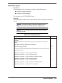
4 BIOS Setup
Setup Overview ..................................................................................................................4-2
What is Setup?...............................................................................................................4-2
When You Should Change the Settings ........................................................................4-2
Some Setting Errors Exist......................................................................................4-2
Settings of CMOS and/or NVRAM Are Cleared ..................................................4-3
Adding or Deleting a Boot Device ........................................................................4-3
The BIOS Version Has Changed...........................................................................4-4
The Host Bus Bridge Configuration Has Changed................................................4-4
iv Contents
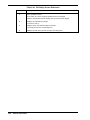
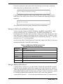
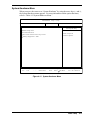
Starting Setup................................................................................................................ 4-4
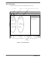
Screen Description ........................................................................................................ 4-5
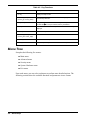
Menu Tree .......................................................................................................................... 4-6
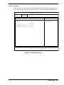
Main Menu Overview ................................................................................................... 4-7
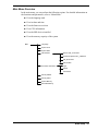
Advanced Menu Overview ........................................................................................... 4-8
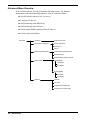
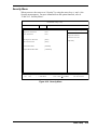
Security Menu Overview .............................................................................................. 4-9
System Hardware Menu Overview ............................................................................. 4-10
Exit Menu Overview................................................................................................... 4-12
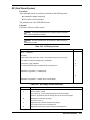
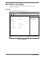
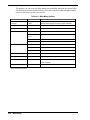
Menu Options and Settings .............................................................................................. 4-13
Main Menu.................................................................................................................. 4-13
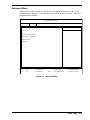
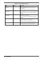
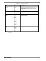
Advanced Menu .......................................................................................................... 4-15
Advanced Submenu ............................................................................................ 4-17
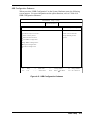
Peripheral Configuration Submenu..................................................................... 4-18
Monitoring Configuration Submenu ................................................................... 4-20
Option ROM Submenu ....................................................................................... 4-22
Extended PCI Slot Submenu ............................................................................... 4-24
Numlock Submenu.............................................................................................. 4-27
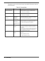
Security Menu............................................................................................................. 4-29
System Hardware Menu.............................................................................................. 4-31
HBB Configuration Submenu ............................................................................. 4-33
PCI Bus Parity Error Assert Submenu ................................................................ 4-35
Master Latency Timer Submenu ......................................................................... 4-37
Multi Transaction Timer Submenu ..................................................................... 4-39
Low MMIO Configuration Submenu.................................................................. 4-41
High MMIO Configuration Submenu ................................................................. 4-43
IO Space Configuration Submenu....................................................................... 4-45
PCI Bus Configuration Submenu........................................................................ 4-47
Console Redirection Submenu ............................................................................ 4-49
Console Redirection – System Serial Port .......................................................... 4-51
Console Redirection – Serial Port 1 .................................................................... 4-53
Shrink Total Number of Interrupt Vectors Submenu.......................................... 4-55
Memory Mapped I/O > 4GB Submenu............................................................... 4-56
Exit Menu............................................................................................................ 4-57
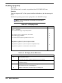
BIOS Virtual DIP Switch................................................................................................. 4-59
What is BIOS Virtual DIP Switch?............................................................................. 4-59
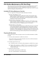
PCI Online Maintenance (PCI Hot Plug) ......................................................................... 4-60
Available PCI Online Maintenance Function ............................................................. 4-60
Preparing the Resources.............................................................................................. 4-60
If a Reboot Occurs ...................................................................................................... 4-61
HBB Configuration Submenu Precaution ........................................................................ 4-63
5 I/O Board Installation
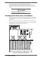
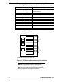
Identifying PCI Slots in the Core Module.......................................................................... 5-2
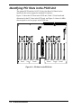
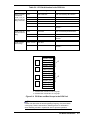
Identifying PCI Slots in the PCIX Unit.............................................................................. 5-5
Selecting a Slot................................................................................................................... 5-8
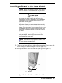
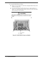
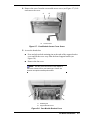
Installing a Board in the Core Module ............................................................................... 5-9
Installing a Board in the PCIX Unit ................................................................................. 5-14
6 Problem Solving
Solving Simple Problems ................................................................................................... 6-2
Troubleshooting the System............................................................................................... 6-4
Contents v
A Technical Specifications
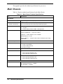
Main Chassis......................................................................................................................A-2
DVD-ROM Drive ..............................................................................................................A-3
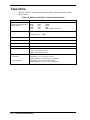
Tape Drive .........................................................................................................................A-4
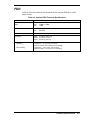
FDD ...................................................................................................................................A-5
B Memory Upgrades
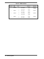
Memory Configurations .................................................................................................... B-2
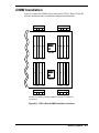
DIMM Installation............................................................................................................. B-3
C Windows 2003 Installation
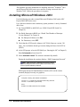
Installing Microsoft Windows 2003 .................................................................................. C-2
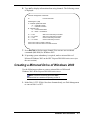
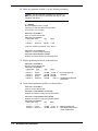
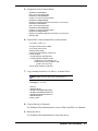
Creating a Mirrored Drive of Windows 2003.................................................................... C-3
Index
vi
Contents
Using This Guide
This User’s Guide provides a quick reference to information about your server system. Its
goal is to familiarize you with your system and the tasks necessary for system setup and
operation.
This guide contains the following information:
!
Chapter 1, “System Overview,” provides an overview of your system and describes your
system’s major system components. See this chapter to familiarize yourself with your
system.
!
Chapter 2, “System Operation,” tells you how to set up the server, how to start up, shut
down, and reboot the system, how to boot the OS, and how to use the DVD-ROM drive
and optional tape drive.
!
Chapter 3, “Service Processor,” describes service processor functions. This chapter
includes information about the SP console, OS console, Virtual SOP, and service
processor commands.
!
Chapter 4, “BIOS Setup,” provides you with a description of the BIOS Setup utility and
its options for configuring the server.
!
Chapter 5, “I/O Board Installation,” shows you how to install I/O boards in the server.
Information includes slot identification and board installation in both the core module
and the optional PCIX unit.
!
Chapter 6, “Problem Solving” contains helpful information for solving problems that
might occur with your system.
!
Appendix A, “Technical Specifications” provides specifications for your server system.
!
Appendix B, “Memory Upgrade” provides memory configuration information necessary
for adding memory to the server. Information includes allowable memory
configurations, memory slot locations, and how to allocate memory.
!
Appendix C, “Windows 2003 Installation” provides information for installing
Microsoft® Windows® 2003 on the Express5800/1000 series server and for creating a
mirrored drive of Windows 2003.
Using This Guide vii
Text Conventions
This guide uses the following text conventions.
Warnings, cautions, and notes have the following meanings:
! WARNING
Warnings alert you to situations that could result in serious personal injury or loss
of life.
! CAUTION
Cautions indicate situations that can damage the system hardware or software.
Note: Notes give important information about the material being described.
viii
!
Names of keyboard keys are printed as they appear on the keyboard. For example, Ctrl,
Alt, or Enter.
!
Text or keystrokes that you enter appear as boldface type. For example, type abc123 and
press ENTER.
!
File names are printed in uppercase letters. For example, AUTOEXEC.BAT.
Using This Guide
Related Documents
In addition to this guide, the following system documentation is included with your server
either as electronic files on EXPRESSBUILDER or as paper copy shipped with your server.
!
System Release Notes
Release Notes provide you with the latest information about your system. This
information was not available to be included in your user's guide at the time it was
developed and released.
!
Site Preparation Guide
The Site Preparation Guide contains information required for preparing the site for your
server installation.
!
Installation Procedures
The Installation Procedures document provides procedures for installing the server at the
site, including unpacking the server, setting up the chassis components, and connecting
the power cables.
! CAUTION
The Express5800/1080Xd server requires installation by qualified personnel such
as an NEC technician and system administrator.
!
ServerCareSM Guide
The ServerCare Guide contains information about NEC’s warranty and server
registration.
Using This Guide ix
Safety Notices
! WARNING
To avoid a risk of injuries, installation should be performed by trained technical
personnel.
Your server is equipped with a front stabilizer. Engage the front stabilizer during
installation. For stability and to distribute the weight, also attach side stabilizers.
Otherwise, the rack may topple over and cause injuries.
If you extend two or more devices from the rack at the same time, the rack may
topple over on you. Extend only one device from the rack at a time.
Exercise great care not to hurt your fingers on the rail when you mount/dismount
the equipment into/from the rack.
Lithium batteries can be dangerous. Improper handling of lithium batteries may
result in an explosion. Dispose of lithium batteries as required by local ordinance.
Replace only with the same or equivalent type battery.
The DVD-ROM drive uses a laser beam. Do not look or insert a mirror inside
while the system is on. A laser beam is invisible; if your eyes get exposed to it,
there is a risk of losing your eyesight.
x
!
Elevated Operating Ambient Temperature – If installed in a closed or multi-unit rack
assembly, the operating ambient temperature of the rack environment may be greater
than the room ambient environment. Therefore, consideration should be given to
installing the equipment in an environment compatible with the maximum rated ambient
temperature of 89.6°F.
!
Reduced air Flow – Installation of the equipment in a rack should be such that the
amount of air flow required for safe operation of the equipment is not compromised.
!
To prevent fires, and damage to rack equipment and supply wiring, make sure that the
rated load of the power branch circuit is not exceeded. Equipment nameplate ratings
should be used when addressing this concern. For more information on installation and
wiring of power-related facilities, contact your electrician or local power company.
!
To prevent electrical shock, connect all rack and rack support equipment to the same
electrical circuit of the building wiring. If you are unsure, check the building wiring to
avoid remote earth conditions.
!
For safe operation, only connect the equipment to a building supply that is in accordance
with current wiring regulations in your country. In the USA those wiring standards are
regulated by Underwriter Laboratories (UL); in the U.K. by the Institution of Electrical
Engineers, (IEE) and in Canada by the Canadian Standards Association (CSA).
Using This Guide
! WARNING
Some locations within the server have high voltage and therefore are very
dangerous. To avoid risk of electric shock, turn off all server power and
disconnect power cables before working inside the server unit.
The main power of your server is turned off by turning off the power source to the
server or removing the power cable.
Before touching the parts in the server, wait for at least 10 to 15 seconds until
residual voltage is discharged.
Safety Notices for Users Outside of the U.S.A. and Canada
!
PELV (Protected Extra-Low Voltage) Integrity: To ensure the extra-low voltage
integrity of the equipment, connect only equipment with mains-protected electricallycompatible circuits to the external ports.
!
Remote Earths: To prevent electrical shock, connect all local (individual office)
computers and computer support equipment to the same electrical circuit of the building
wiring. If you are unsure, check the building wiring to avoid remote earth conditions.
!
Earth Bonding: For safe operation, only connect the equipment to a building supply
that is in accordance with current wiring regulations in your country. In the USA those
wiring standards are regulated by Underwriter Laboratories (UL); in the U.K., by the
Institution of Electrical Engineers, (IEE) and in Canada by the Canadian Standards
Association (CSA).
Using This Guide xi
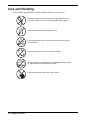
Care and Handling
Use the following guidelines to properly handle and care for your system.
Protect the system from extremely low or high temperatures. Let
the system warm (or cool) to room temperature before using it.
Keep the system away from magnetic forces.
Keep the system dry. Do not wash the system with a wet cloth or
pour fluid into it.
Protect the system from being bumped or dropped.
Check the system for condensation. If condensation exists, allow it
to evaporate before powering on the system.
Keep the system away from dust, sand, and dirt.
xii
Using This Guide
1
System Overview
!
Overview
!
System Features
!
System Chassis
!
System Functions
!
Expansion
!
Security
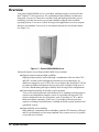
Overview
Your Express5800/1080Xd server is a modular, multiprocessing server based on the
Intel® Itanium® 2 64-bit processor. The combination of Intel Itanium 2 architecture,
along with your server’s innovative crossbar switch and high-speed memory access
technology, provides for massive power and scalability using the latest available
operating systems. Your server is ideal for large-scale applications as well as compute
intensive environments. Your server is conveniently housed in a rack-mount cabinet
(see Figure 1-1).
Figure 1-1. Express5800/1080Xd Server
Advanced features of your Express5800/1080Xd server include:
!
High-speed processing and high scalability
High-speed processing is realized through a combination of the new Intel CPU
and NEC crossbar switch and high-speed memory access technologies. In
addition to support for up to 8 CPUs, the server employs the advanced PCI-X bus
to connect peripheral and network devices and can be configured with up to 26
I/O slots, demonstrating the high scalability ideal for large-scale configurations.
!
Partitioning functionality for flexible system operation
Your server can be partitioned at the hardware level, enabling each subsystem to
operate as an independent computer system. It is possible to divide an 8 CPU
system configuration into two subsystems, each of which has 4 CPUs, and let
them each operate separately. In this way, it’s possible to allocate processor
capacity according to workload status, resulting in flexible system operation and
guaranteed security.
!
High reliability and availability
Many hardware components allow redundancy, and the CPU/memory cell board
and I/O card hardware are hot-swap compliant. Easy system recovery is possible
even at the time of failure.
1-2 System Overview
System Features
Your system features the following major components:
!
Quad high-performance Intel® Itanium® 2 64-bit 1.3GHz/3MB or 1.5GHz/6MB
processors per CellV Board.
!
Up to two CELLV Boards, each supporting the installation of up to 4 CPUs
(Intel Itanium 2 processors) for a total of 8 CPUs in the system.
Each CELLV Board has 16 DIMM sockets and supports from 4 GB (using four
1-GB DIMMs) to 16 GB (using sixteen 1-GB DIMMs) of ECC SDRAM fourway interleaved memory.
!
Core Module that includes:
Interface to connect with the optional PCIX Unit (1.6G interface)
Twelve PCI-X expansion slots for add-in boards. A Basic I/O Board and
VGA card are installed in two of the PCI-X expansion slots. The Core
Module includes eight 64-bit/66-MHz hot-swap PCI-X slots and four
64-bit/133-MHz hot-swap PCI-X slots.
Two USB interface ports, two IDE interface ports, Mouse interface and
Keyboard interface ports.
ATI RAGE XL Video Graphics Array (VGA) controller with 8MB of video
memory (VRAM)
DVD-ROM unit
Bay for an optional DAT drive or optional USB FDD unit
Four hot-swap SCSI hard disk drive bays accessible from the front of the
chassis; each drive bay can contain a 36-GB, 73-GB, or 146-GB SCSI hard
disk drive.
!
Intelligent Service Processor-Clock (iSP-C) Board which provides diagnostic
functions and clock distribution.
!
Hot-swap SCSI disk drive backplane; a failed drive can be removed and replaced
with a new drive without system power being turned off (if software mirror has
been configured).
!
Hardware monitors (temperature, fans, and voltage) and software monitors to
indicate failures.
!
The main chassis supports three power supply modules. Only two of the modules
are required to power the system. The additional power supply module provides
hot-swappable redundant power (i.e., the system will continue to operate with a
single power supply failure). With three power modules installed, one power
module can be easily removed or installed from the front of the chassis without
turning the system power off.
System Overview
1-3
!
!
Ten fan modules are located throughout the system. Any fan module can easily
be removed and installed, without powering down the system.
Optional PCIX Unit in two versions, Base Unit and Core Unit:
14 PCI-X expansion slots in a Base Unit model
12 PCI-X expansion slots, a Basic I/O Board with 2 USB, 2 IDE, and
1 Keyboard interfaces, a VGA card with an analog interface, and a
DVD-ROM unit in a Core Unit model to allow a second bootable partition.
Bay for an optional DAT or optional USB FDD unit
Six hot-swap SCSI hard disk drive bays for up to 6 hard drives.
See Appendix A, “Technical Specifications,” for a list of system specifications.
1-4 System Overview
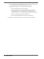
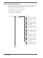
System Chassis
The following figures show the external and internal server features.
Front View
Figure 1-2 shows the front system features (front door and covers are not shown in the
figure).
A
M
B
C
L
D
K
E
J
F
I
G
H
A
AC Power Switch
H
PCIX Power Unit with Two
Power Supplies (optional)
B
AC Power Switches for
Optional Power Supply
Modules
I
Base or Core PCIX Unit
(optional)
C
Filler Panels
J
1080Xd Main Chassis
D
Power/Status LEDs
K
Main Chassis Power Supply
Modules
E
Bay for optional DAT Tape
Drive or USB FDD
L
DVD-ROM Drive
F
Hard Disk Drive Bays
M
Emergency AC Power Switch
(for optional PCIX Unit)
G
Cell Cooling Fans
Figure 1-2 Front View
System Overview
1-5
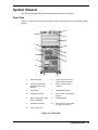
Top View
Figure 1-3 shows the components within the Main Chassis.
D
E
C
F
B
A
A
DVD ROM Drive
D
Core Module Ejector
B
Power Supply Modules (3)
E
PCI-X Expansion Slots
C
Core Module Fans
F
Hard Disk Drive Fans
Figure 1-3. Main Chassis
1-6 System Overview
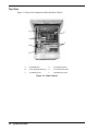
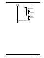
Right Side View
Figure 1-4 shows the system right side features.
B
A
C
D
E
Figure 1-4. 1080Xd Right Side View
A
Service Processor and
Clock (ISP-C)
D
Cell #0 Board
B
1080Xd Main Chassis
E
Cabinet
C
Cell #3 Board
System Overview
1-7
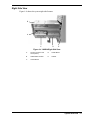
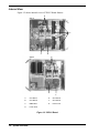
Internal View
Figure 1-5 shows internal views of CELLV Board features.
D
Side A
C
A
B
G
Side B
E
F
A
CPU Slot #1
E
CPU Slot #2
B
CPU Slot #3
F
CPU Slot #0
C
DIMM Slots
G
Power Pods
D
Power Pods
Figure 1-5. CELLV Board
1-8 System Overview
Main Components
The following sections provide information about the components in the main chassis.
Itanium 2 Processors
Depending on system configuration, your system includes four or eight Intel Itanium 2
64-bit 1.3-GHz/3-MB or 1.5-GHz/6.0-MB processors. Four Intel Itanium 2 processors
are installed within one CELLV board. See Figure 1-5. A second CELLV board has an
additional four Intel Itanium 2 processors. All processors installed in your system must
be of identical bus and core speed.
System Memory
Each CELLV board in your system contains sixteen 168-pin DIMM sockets.
See Figure 1-5. Memory DIMMs must be populated four at a time with 1-GB ECC
SDRAM DIMMs. Depending on the number of DIMMs installed, your system may
include from 4 GB up to a maximum of 32 GB of memory using 1-GB DIMMs.
PCI-X Core Module
The server’s expansion capabilities meet the needs of file and application servers for
high performance I/O by providing twelve hot-swap PCI-X expansion slots within the
Core Module. The Core Module consists of a CrossBar Controller (XBC) and an I/O
Router (IOR). The Core Module can be connected with up to two CELLV Boards, to
control data transfers between the CELLV Boards.
The Core Module includes five full-length and three half-length 64-bit/66-MHz hotswap PCI-X slots and three full-length and one half-length 64-bit/133-MHz hot-swap
PCI-X slots. The PCI-X slots allow PCI-X boards to be installed or removed while the
server is powered on (if the operating system supports the Hot Plug PCI function). A
Basic I/O Board to support standard I/O interface and a video VGA controller board are
installed in the Core Module. The Basic I/O Board and video VGA board are not hotswappable.
Note: Your operating system must support the Hot Plug PCI
function.
A DVD-ROM drive is installed in the Core Module as standard equipment. Optionally,
a DAT tape drive or USB FDD and up to 4 disk storage hard disk drives may be added
to the Core Module. See Figure 1-2.
System Overview
1-9
Service Processor Board
The Service Processor Board (iSP-C Board) controls power and monitors status of all
components (see Figure 1-4). The board uses a PowerPC chip as the processor for
iSP-C, memory, LAN, serial interface, and clock distribution functionality. The Service
Processor Board performs initialization of the system, RAS functions, diagnostic
functions, failure management of the system, and clock generation and distribution.
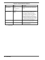
Power/Status LEDs
Three LEDs are visible on the front of the server system cabinet (see Figure 1-2):
!
AC
!
DC
!
Status.
See Table 1-1 for a description of the LEDs.
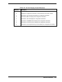
Table 1-1. Power/Status LEDs
LED
LED State
AC
Green
DC
Status LED
Description
On
AC power on.
Off
AC power off.
On
DC power on (lights when DC48V is supplied).
Off
DC power off.
Green
On
OS ready (one node or more).
Amber
On
System is in Maintenance mode (execution of the SP “cm”
command).
Off
Failure or offline state.
Green
System Functions
The following subsections describe select system functions.
Partitioning
If your system includes two CELLV Boards and an optional core PCIX expansion unit,
your server may be partitioned at the hardware level into two distinct subsystems,
enabling each subsystem to operate as an independent computer system, each with its
own operating system.
It is possible to divide the eight-CPU system into two subsystems, each of which has
four CPUs, and let them each function separately. In this way it’s possible to allocate
processor capacity according to workload status, resulting in flexible system operation.
Each partition is physically isolated by the hardware settings; a software error does not
affect the other partitions. Thus the system can maintain high security.
1-10 System Overview
Each partition consists of a CELLV Board and a core PCIX unit. Multiple OS instances
can run on different partitions independently. If a partition has at least one PCIX unit
with basic I/O, the CELLV Boards and the PCIX units can be flexibly assigned to any
partition.
The Service Processor manages the partitioning settings and configuration changes.
Chipset and Crossbar Switch
NEC developed a high-performance chipset and crossbar switch that is based on
supercomputer mainframe technology. The crossbar switch connects the CELLV
boards. The crossbar switch has a low latency as well as high data bandwidth. While
comprising Cache Coherent Non-Uniform Memory Access (cc-NUMA) architecture,
the system employs the chipset and crossbar switch technology in achieving near
uniform high-speed memory access.
Server Management
The Service Processor supports many management functions compatible to the
Advanced Configuration and Power Interface (ACPI) and Intelligent Platform
Management Interface (IPMI).
The system supports the following ACPI features:
!
Configuration information tables interface from a platform.
!
Software power off controls, etc.
The Service Processor also works as a management controller defined in IPMI. It
supports the following IPMI features.
!
Provides Field Replaceable Unit (FRU) information to System Management
Services (SMS) running on the operating system.
!
Monitors system power, fan speed, and temperature conditions.
!
Monitors stall occurrences during the power-up sequence, OS loading, and
normal running using a watchdog timer, etc.
The Service Processor provides the following management features:
!
Error handling (error monitoring, logging, diagnostics, and reporting)
!
System reset
!
System configuration management
!
Firmware update, etc.
The SMS running on a PC can control the above functions using the Service
Processor’s system management LAN port, which can support TELNET, FTP, and
SNMP protocol. With the combination of the Service Processor and the
SystemGlobe/GlobalMaster software, the Express 5800/1080Xd supports automatic
reconfiguration of partitions based on the conditions pre-defined in the
SystemGlobe/GlobalMaster.
System Overview
1-11
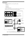
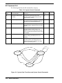
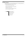
Expansion
The Express5800/1080Xd server can be expanded by adding:
!
Memory
!
I/O boards
!
Disk drives
!
PCIX Expansion Unit.
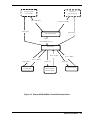
See Figure 1-6 for a diagram of the Express5800/1080Xd system configuration. See the
following sections for a description of system expansion capabilities.
I t ani um2
4 GB memory upgrade
(using 1-GB DIMMs)
Standard: one CELLV Board with 4 CPUs (Itanium 2);
a second CELLV Board with 4 CPUs (Itanium2)
Up to 4 sets of the above
memory per CELLV Board or up
to 16 GB can be installed
per board.
Core Module
DVD-ROM drive
DVD-ROM/
CD-ROM
N
E
C
Magnetic tape
DD4 or
USB FDD
(Optional)
SP Console
(Standard)
RS232C
( Consol e)
Server Management
LAN Interface
Ethernet cable
10/ 100BASE- TX
Optional PCIX Unit
Up to 4 HDDs (Disk Storage) can be
installed.
1.6G cable
DVD-ROM drive
DVD-ROM/
CD-ROM
1. 6G
N
E
C
Figure 1-6. Express5800/1080Xd System Configuration
1-12 System Overview
Magnetic tape
DD4 or
USB FDD
(Optional)
! CAUTION
Contact qualified personnel, such as your System Administrator or
an NEC Technician, for adding or removing server components.
CELLV Board
Each CELLV Board supports:
!
4 Intel Itanium 2 processors
!
16 DIMMs.
The system supports 2 CELLV Boards for a total of eight Itanium 2 processors and up
to 32 DIMMs.
CPUs
Each CELLV Board supports 4 Itanium 2 processors. The system supports the
following processor types:
!
Intel Itanium 2 1.3GHz/3MB of level 3 cache
!
Intel Itanium 2 1.5GHz/6MB of level 3 cache
The same type processor must be used in the system. The two types cannot be mixed
within a single system.
Memory
Each CELLV Board supports up to 16 DIMMs in the following configurations:
!
Memory must be installed in groups of 4 DIMMs of the same capacity.
!
Memory capacity can vary between different groups
!
At least one group of four DIMMs is required in the system.
!
Each CELLV Board supports up to 4 groups of 4 DIMMs.
!
A memory group currently includes a group of four 1-GB DDR DIMMs for total
capacity of 4 GB in a group.
!
Maximum memory capacity using currently available 1-GB DIMMs is 16 GB
per CELLV board or 32 GB on two CELLV boards.
For detailed memory configuration information, see Appendix B. in this guide.
Optional PCIX Unit
A PCIX Unit can be added and connected to the Main Chassis. The PCIX Unit connects
to the Core Module via a 1.6-GB interface cable (dedicated cable for connecting the
unit).
A PCIX Unit requires a Power Bay Unit. Up to six Distributed Power Supply (DPS)
modules can be installed in a Power Bay Unit.
System Overview
1-13
Peripheral Devices
Disk drives can connect to a SCSI board, and ATA devices can connect to the Basic I/O
Board. You can also connect peripheral devices via PCI cards installed in the optional
PCIX Unit.
Security
To help prevent unauthorized entry or use of the system, the server provides the
following security features:
!
Locked areas require a security key for entry. Locked areas include the rear
chassis door and drive bay units.
!
The BIOS Setup utility provides user and administrative password security,
protecting the system from unauthorized operation.
!
Console operation requires the entry of login authentication with a login account
and password.
1-14 System Overview
2
System Operation
!
Setting Up the Server
!
Starting Up the System
!
Shutting Down the System
!
Rebooting the System
!
Booting the OS
!
Using the DVD-ROM Drive
!
Using an Optional Tape Drive
Setting Up the Server
Use the following procedure to set up the server.
Note: See Chapter 1 of this user’s guide to become
familiar with server features, such as the location of system
switches, indicators, and main chassis components.
1. Check that the server has been installed as described in the
Express5800/1080Xd/1160Xd/1320Xd Site Preparation Guide and
Express5800/1080Xd Installation Procedures. This server requires
installation by qualified personnel such as an NEC technician and system
administrator.
2. Make sure that any optional components other than I/O cards or boards,
have been installed by an NEC technician.
If you have an I/O card or board to install, install it now (see Chapter 5, “I/O
Board Installation”).
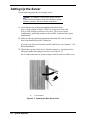
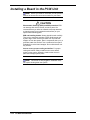
3. Unlock the rear door of the server with the security key. Open the door by
lifting the handle and turning it clockwise (see Figure 2-1).
Server cable connectors for system setup are located at the rear of the server.
B
A
A
Lift Handle
B
Turn Clockwise
Figure 2-1. Opening the Rear Server Door
2-2 System Operation
4. Locate the server LAN cable at the rear of the server cabinet. Connect a
client PC to the server LAN connection.
Note: A LAN cable either comes already connected to
the Service Processor board or it is connected by the NEC
technician during the server installation.
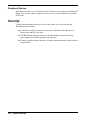
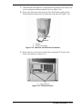
5. Connect peripheral devices, such as a monitor, mouse, and keyboard, to the
rear of the server. See Figure 2-2 for server connector locations.
A
B
A
VGA Monitor Connector
B
Mouse and Keyboard Connectors
Figure 2-2. Server Connector Locations
! CAUTION
When connecting a cable to an I/O board, be sure to leave
enough cable free for sliding the main chassis or PCIX unit
out of the cabinet. Route the cable so it does not get pinched
or damaged.
Route the external device cables under the rear door frame
and out of the way of the rear server door.
6. Close and lock the rear server door.
System Operation 2-3
Starting Up the System
Start up the server system as follows.
1. Make sure all external devices, such as the console, keyboard, and mouse
have been connected, and the power cords are connected (see the previous
section, “Setting Up the Server”).
2. Turn on the circuit breaker or main switch to the system power source.
Note: If the server power cord is connected to a power
control unit such as an UPS (Uninterruptive Power Supply),
make sure that the power control unit is powered on.
3. Power on the console and any other external devices.
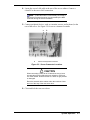
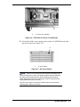
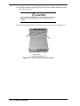
4. At the rear of the server cabinet, turn on the AC power circuit breaker for the
Main Chassis (see Figure 2-3), and if installed, for the optional PCIX Unit
(see Figure 2-4).
A
A
AC Power Circuit Breaker
Figure 2-3. Main Chassis AC Power Circuit Breaker
2-4 System Operation
A
A
AC Power Circuit Breaker
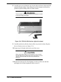
Figure 2-4. PCIX Unit AC Power Circuit Breaker
5. On the front of the server cabinet, power on the AC POWER switch at the
top of the system (see Figure 2-5).
A
A
AC Power Switch
Figure 2-5. AC Power Switch
Note: If the AC-Link function has been enabled, following the AC
power being turned on, and if the operating system has been installed,
the system will automatically boot up the operating system without
further intervention (refer to the description of the SU command in the
Express5800/1080X Service Guide).
If the AC-Link function has not been enabled, then continue with this
“Starting Up the System” procedure.
System Operation 2-5
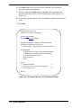
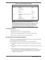
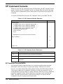
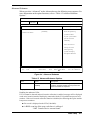
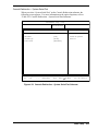
6. Press Esc on the service processor (SP) keyboard. The iSP (service
processor) login prompt appears.
7. Enter the login name spfw and password nec. (The login name and
password are default values.) The iSP Main Menu screen appears (see
Figure 2-6).
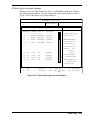
8. At the iSPyz prompt, enter the iSP command s to enter the SP command
mode.
9. Press Esc.
Integrated Service Processor.
Cabinet-ID:xx, Location:y, State:ssssss
iSP login: spfw<ENTER>
iSP password: xxxxxxxx<ENTER>
Copyright (C) 2002 NEC Corporation, All Rights Reserved.
Welcome to Integrated Service Processor.
iSP FW version : 01.00 generated on 01/31/2002 19:20:33
iSP MAIN MENU
0) OS(BIOS) serial console of partition#0 (INITIALIZING)
1) OS(BIOS) serial console of partition#1 (RUNNING)
V) Virtual System Operator Panel
S) iSP commands
E) Exit
iSPyz> s
***** SP Command Mode
***** enter ESC to do the command input effectively
***** enter CTRL+B to quit
****
*****
*****
iSPyz:--->
Figure 2-6. SP Console Screen – SP Firmware Activated
2-6 System Operation
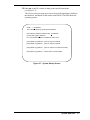
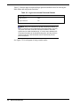
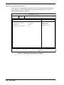
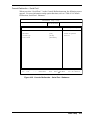
10. Enter up on the SP console to bring up the specified partitions
(see Figure 2-7).
The service processor turns on power to the specified partitions, initializes
the hardware, and hands off the control to the BIOS. The BIOS boots the
operating system.
iSPyz:---> up<ENTER>
This command will bring up the specified partition.
Enter partition number (0-7/all/CR=exit) : all<ENTER>
Execute OK? (y/[n]) y<ENTER>
UP command was accepted. All partitions will run soon.
[iSPyz:INFO.ccc] partition 0 : power on sequence started.
[iSPyz:INFO.ccc] partition 1 : power on sequence started.
:
[iSPyz:INFO.ccc] partition 1 : power on sequence completed normally.
:
[iSPys:INFO.ccc] partition 1 : handed off the control to BIOS.
Figure 2-7. System Startup Screen
System Operation 2-7
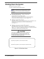
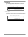
Shutting Down the System
Shut down the system as follows.
1. Select a method to shut down the system:
Note: If supported by your operating system, Windows
Shut Down is the recommended method of shutting down
the system.
!
Recommended shutdown – Windows Shut Down
(if supported by the operating system):
Shut down the operating system (OS). The related partition(s)
automatically shutdown and power off (see Figure 2-8).
!
Shutdown using the DN command.
Enter dn on the SP console to shut down the system. If software is not
running, this command powers off the selected partition(s)
(see Figure 2-9).
!
Shutdown system power using the DF command:
Enter df on the SP console to force a shut down of the system (see
Figure 2-10). This power shutdown method forces a partition shutdown
without prior warning to the operating system.
! CAUTION
This SP df command turns off system power regardless of
OS or BIOS operation and without notifying either. This
command corresponds to a power button override function
of a system with a physical power button.
[iSPyz:INFO.ccc] partition 0 : power off sequence started.
:
:
:
[iSPyz:INFO.ccc] partition 0 : power off sequence completed normally.
Figure 2-8. OS Shut Down Screen
2-8 System Operation
iSPyz:---> dn<ENTER>
System power will be turned off if the software (OS) is NOT running.
Only power button interrupt will be generated if the software (OS) is running.
If you want to turn off the system power in any system state, use DF command.
Enter partition number (0-7/all/CR=exit) : all<ENTER>
Execute OK? (y/[n]) y<ENTER>
DN command was accepted. System power of all partitions will be turned off or
power button interrupt will be generated soon.
[iSPyz:INFO.ccc] partition 0 : power button interrupt.
[iSPyz:INFO.ccc] partition 1 : power off sequence started.
:
[iSPyz:INFO.ccc] partition 1 : power off sequence completed normally.
Figure 2-9. DN Command Power Shut Down Screen
iSPyz:---> df<ENTER>
CAUTION: System power will be turned off without any notice to the softwares
even if they are running.
Enter partition number (0-7/all/CR=exit) : all<ENTER>
Execute OK? (y/[n]) y<ENTER>
DF command was accepted. System power of all partitions will be turned off soon.
[iSPyz:INFO.ccc] partition 0 : power off sequence started.
[iSPyz:INFO.ccc] partition 1 : power off sequence started.
:
:
:
[iSPyz:INFO.ccc] partition 1 : power off sequence completed normally.
Figure 2-10. DF Command Power Shut Down Screen
2. Check that the DC power is off. The SP console displays a “power off”
message (see Figures 2-8, 2-9, and 2-10).
This is a normal system “power off.” For a complete system power off,
perform the following steps.
Note: The following steps perform a “complete system
power off.” A “complete power off” is not normally performed.
System Operation 2-9
3. Power off the console.
4. Turn off AC power to the system:
!
At the top front of the system cabinet, press the AC power switch.
!
At the rear of the system, power off the circuit breaker to the optional
PCIX Unit, if installed.
!
At the rear of the system, power off the circuit breaker to the Main
Chassis.
5. Power off peripheral devices not powered by the server.
6. Power off the main circuit breaker or power distribution board.
Note: If the server power cord is connected to a power
control unit such as an UPS (Uninterruptible Power Supply),
refer to the UPS user's guide for proper power-off
procedures.
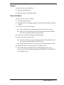
Using Exception Procedures
The following sections describe exception procedures for restarting the system.
Note: For detailed information about SP commands,
see “SP Command Reference” in Chapter 3.
Dump
Use the dump function to request the operating system to perform its memory
dump process. You can select either to restart or not to restart using the
operating system settings. To use the dump function, the system must be
running the operating system.
To dump, enter dp at the SP command prompt.
Cold Reset
Use a cold reset to reset the entire system, including memory, when there is a
hardware error condition.
Perform a cold reset as follows:
1. Stop the operating system.
2. Enter rs at the SP command prompt.
2-10 System Operation
Restart
Perform a system restart as follows:
1. Stop the operating system.
2. Enter pc at the SP command prompt.
Power On Reset
Perform a power on reset as follows:
1. Stop the operating system.
2. Enter dn at the SP command prompt. Check that the main chassis fans stop
rotating.
3. Turn off AC power to the system:
!
At the top front of the system cabinet, press the AC power switch.
!
At the rear of the system, power off the circuit breaker to the optional
PCIX Unit, if installed, and to the main chassis.
4. Wait 10 to 15 seconds to discharge residual voltage.
5. Turn on AC power to the system:
!
At the rear of the server, power on the AC power circuit breaker to the
main chassis, and if installed to the PCIX Unit.
!
On the front top of the server cabinet, power on the AC power switch.
6. On the SP console, enter the login account and password.
7. On the SP console, enter up at the SP command prompt. The service
processor turns on DC power and initializes the hardware. The BIOS boots
the operating system.
System Operation 2-11
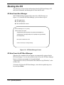
Booting the OS
The following sections include information about the EFI Boot Manager, EFI
shell, shell commands, and booting the OS from the EFI shell.
OS Boot from Boot Manager
The EFI Boot Manager automatically starts after a BIOS bootup (see
Figure 2-11). From the EFI Boot Manager, you can choose to go to:
!
EFI applications
!
EFI shell prompt
!
Boot maintenance menu.
EFI Boot Manager ver 1.10 [14.56]
Please select a boot option
Acpi(PNP0A03,0)/Pci(2|1)/Ata(Primary,Master)/CDROM(Entry1)
Acpi(PNP0A03,1)/Pci(3|0)/Scsi(Pun0,Lun0)/HD(Part1,Sig17FB0000)
EFI Shell [Built-in]
Boot option maintenance menu
Use the arrow keys to change settings
Figure 2-11. EFI Boot Manager Screen
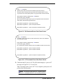
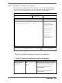
OS Boot from the EFI Boot Manager
When the OS is installed, OS boot options are automatically registered in the
EFI Boot Manager. You can select and boot the OS from the EFI Boot Manager.
Figure 2-12 shows an example of a boot path defined
“Acpi(PNP0A03,0)/Pci(3|0)/Scsi(Pun0,Lun0)/HD(Part1,Sig17FB0000)” as the
OS boot disk.
To boot the OS from the EFI Boot Manager, select the boot path using arrow
keys and press Enter.
2-12 System Operation
EFI Boot Manager ver 1.10 [14.56]
Please select a boot option
Acpi(PNP0A03,0)/Pci(2|1)/Ata(Primary,Master)/CDROM(Entry1)
Acpi(PNP0A03,1)/Pci(3|0)/Scsi(Pun0,Lun0)/HD(Part1,Sig17FB0000)
EFI Shell [Built-in]
Indicates OS Boot Disk
Boot option maintenance menu
Use the arrow keys to change settings
Figure 2-12. OS Boot from EFI Boot Manager Screen
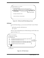
EFI Shell
From the EFI Boot Manager, you can activate the EFI shell. Use the EFI shell
to:
!
Read the system file of the Boot device.
!
Copy files.
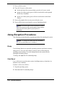
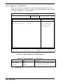
When you select the EFI Shell from the EFI Boot Manager, the EFI Shell screen
appears (see Figure 2-13).
Loading.: EFI Shell [Built-in]
EFI Shell version 1.10 [14.56]
Device mapping table
fs0
: Acpi(PNP0A03,3)/Pci(2|0)/Scsi(Pun0,Lun0)/HD(Part1,Sig0A7C0000)
blk0
: Acpi(PNP0A03,3)/Pci(2|0)/Scsi(Pun0,Lun0)
blk1
: Acpi(PNP0A03,3)/Pci(2|0)/Scsi(Pun0,Lun0)/HD(Part1,Sig0A7C0000)
blk2
: Acpi(PNP0A03,3)/Pci(2|0)/Scsi(Pun0,Lun0)/HD(Part2,Sig0A7C0000)
blk3
: Acpi(PNP0A03,0)/Pci(2|1)/Ata(Primary,Master)
List of disk
drives identified
by the system
Shell>
EFI shell prompt
Figure 2-13. EFI Shell Screen
System Operation 2-13
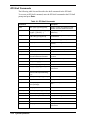
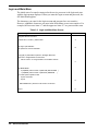
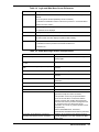
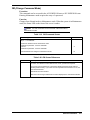
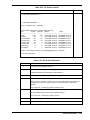
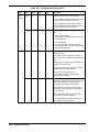
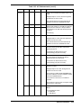
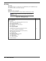
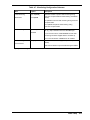
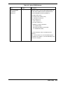
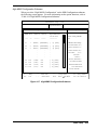
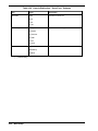
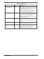
EFI Shell Commands
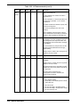
The following table lists and describes the shell commands in the EFI shell.
To execute an EFI shell command, enter the EFI shell command at the EFI shell
prompt and press Enter.
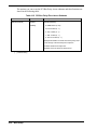
Table 2-1. EFI Shell Commands
Command
Description
alias
alias [-d|-v|-b] [sname] [value]
Displays, creates, and deletes the alias
definition in the EFI Shell environment.
attrib
attrib [+a|-a] [+s|-s] [+h|-h] [+r|-r]
[-b] [file ...] [directory ...]
Displays and changes the attributes of the
file/directory.
bcfg
bcfg driver|boot [dump –v] [add
# file “desc”] [rm #] [mv # #]
Displays and changes the configuration of
the driver/boot.
break
break
Executes a debugger breakpoint.
cd
cd [path]
Displays and changes the current
directory.
child
child Handle
Displays the device tree under the handle.
cls
cls [color]
Clears the standard output.
comp
comp file1 file2
Compares the contents of the two files.
connect
connect [-r] Handle# |
DeviceHandle# DriverHandle#
Binds the driver to the device and starts
the driver.
cp
cp [-r] src [src ...] [dst]
Copies the file/directory.
date
date [mm/dd[yy]yy]
Displays and sets the date.
dblk
dblk device [Lba] [blocks]
Dumps the block device.
dh
dh [-p prot_id] [-b] | [handle]
Displays the handle in the EFI
environment.
disconnect
disconnect DeviceHandle#
[DriverHandle# [ChildHandle#]]
| [-r]
Disconnects the device and the driver.
Dmem
dmem [Address] [Size] [;MMIO]
Dumps memory.
dmpstore
dmpstore
Displays the NVRAM variable.
echo
echo [-on|-off]
Displays messages, or switches on/off
echo.
echo [message]
edit
edit [file]
Edits the ASCII/UNICODE file.
EfiCompress
EfiCompress [InFile] [OutFile]
Compresses the file.
EfiDecompress
EfiDecompress [InFile] [OutFile]
Decompresses the file.
err
err [ErrorLevel]
Displays and changes the error level.
exit
exit
Exit from the EFI Shell.
getmtc
getmtc
Displays the current counter value.
guid
guid [-b]
Displays the GUID in the EFI
environment.
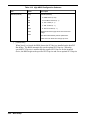
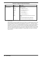
2-14 System Operation
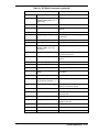
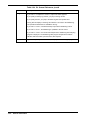
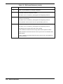
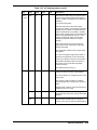
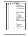
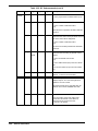
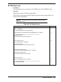
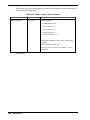
Table 2-1. EFI Shell Commands (continued)
Command
Description
help
help [-b] | [cmd]
Displays the help information.
hexedit
hexedit [[-f] FileName | [-d
DiskName Offset Size] | [-m
Offset Size]
Edits in hexadecimal mode.
load
load file [file ...]
Loads the EFI driver.
LoadPciRom
LoadPciRom [FileName]
Loads the PCI option ROM image from
the file.
ls
ls [-b] [-r] [-a [attrib]] [file]
Displays the directory/file list.
map
map [-r|-v|-d] [sname] [handle] [b]
Displays and defines the mapping
information.
memmap
memmap [-b]
Displays the memory map.
mkdir
mkdir dir [dir ...]
Creates a directory.
mm
mm Address [Width 1|2|4|8]
[;MMIO| ; MEM| ; IO | ;PCI]
[:Value] [-n]
Displays and changes MEM/IO/PCI.
mode
mode [row col]
Displays and changes the mode of the
console output device.
mount
mount BlkDevice [sname]
Mounts the file system on the block
device.
mv
mv src [src ...] [dst]
Moves the file/directory.
OpenInfo
OpenInfo Handle
Displays the protocol of the handle/agent.
pause
pause
Displays a message and waits for input.
pci
pci [Bus Dev [Func] [-i] [-s
[Seg]]]
Displays the configuration space of the
PCI device.
reset
reset [-w [string]]
Resets the system.
rm
rm [-q] file [file ...]
Deletes the file/directory.
rm [-q] directory [directory ...]
set
set [-d|-v|-b] [sname [value]]
Displays, creates, changes, and deletes
the EFI environment variable.
setsize
setsize newsize file
Sets the file size.
stall
stall microseconds
Stalls the processor in units of
microseconds.
time
time [hh:mm[:ss]]
Displays the current time or sets the time.
touch
touch [-r] filename
Sets the current date/time to the date/time
attribute of the file.
type
type [-a|-u] [-b] file [file ...]
Displays the content of the file.
unload
unload [-n] [-v] HandleIndex
Unloads the protocol image.
ver
ver
Displays the version information.
System Operation 2-15
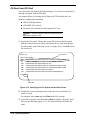
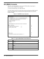
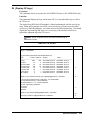
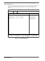
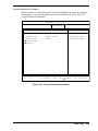
OS Boot from EFI Shell
You can boot the OS from the EFI Boot Manager. You can also boot the OS by
entering commands from the EFI Shell.
An example follows for booting the OS from the SCSI hard disk drive in a
hardware configuration containing:
!
IDE DVD-ROM (Master)
!
SCSI HDD: OS boot disk
!
External LAN card built into the Expansion PCI slot.
Note: Cards are available if they are supported by the
application programs or OS.
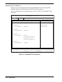
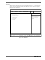
1. Specify the file system. Change the current file system to the file system
with the connected boot device by entering the device at the Shell prompt.
For the example in the following screen (see Figure 2-14), enter fs0: for the
fs0 boot device.
Boot device
Shell> map
Device mapping table
fs0
: Acpi(PNP0A03,3)/Pci(2|0)/Scsi(Pun0,Lun0)/HD(Part1,Sig0A7C0000)
fs1
: Acpi(PNP0A03,0)/Pci(2|1)/Ata(Primary,Master)/CDROM(Entry1)
blk0 : Acpi(PNP0A03,3)/Pci(2|0)/Scsi(Pun0,Lun0)
blk1 : Acpi(PNP0A03,3)/Pci(2|0)/Scsi(Pun0,Lun0)/HD(Part1,Sig0A7C0000)
blk2 : Acpi(PNP0A03,3)/Pci(2|0)/Scsi(Pun0,Lun0)/HD(Part2,Sig0A7C0000)
blk3 : Acpi(PNP0A03,0)/Pci(2|1)/Ata(Primary,Master)
blk4 : Acpi(PNP0A03,0)/Pci(2|1)/Ata(Primary,Master)/CDROM(Entry1)
Shell> fs0:
Enter fs0:
Figure 2-14. Specifying the File System on the Shell Screen
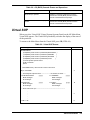
2. Change the current working directory to the directory in which the OS
loader is stored.
For example, enter cd os and press Enter at the Fs0:\ prompt.
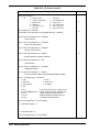
3. At the fs0:\os prompt, enter ls and press Enter to display a directory list of
files (see the following Figure 2-15). The list includes the OS loader file
name.
2-16 System Operation
4. Start the OS loader by entering the directory file name, in this example,
setupldr.efi, at the fs0:\os prompt and press Enter.
fs0:\> cd os
fs0:\os> ls
Directory of fs0:\os
03/13/00 05:44p <DIR>
2,048 .
03/13/00 05:44p <DIR>
512 ..
12/22/99 00:58p
r
635,392 setupldr.efi
1 File
635,392 bytes
2 Dirs
2,560 bytes
fs0:\os> setupldr
Start OS Loader.
Figure 2-15. Starting the OS Loader from Shell
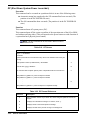
Notes for OS Installation
See the following notes requiring attention when installing the OS:
!
Adding a SCSI card to a free slot and connecting a disk to the SCSI card
after the OS installation, might change the numbering of the disk and
prevent an OS boot from that disk.
!
PCI12 slot is set to not run Option ROM BIOS as default. Running
Option ROM BIOS on PCI12 slot requires changing the settings of the
slot with BIOS setup before booting the OS.
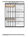
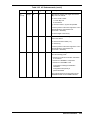
EFI Device Path
Each device installed in the system is managed with an “EFI Device Path.” The
following information describes EFI device paths.
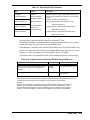
See the following examples and Table 2-2 for device path formats for devices
conforming to EDD3.0 specification:
Example: SCSI cards and disks installed on the PCI bus:
Acpi(PNP0A03, 1)/Pci(2|0)/Scsi(Pun0,Lun0)/HD(Part1,SigFF050000)
Example: DVD-ROM device connected to the IDE Secondary channel:
Acpi(PNP0A03,0)/Pci(2|1)/Ata(Secondary,Master)/CDROM(Entry1)
System Operation 2-17
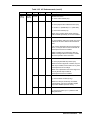
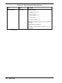
Table 2-2. Formats Conforming to EDD3.0 Specification
Path Display
Description
Acpi(PNP0A03, X)
Indicates that the device is installed under the PCI host bus.
X: PCI host bus bridge number (starting with 0).
Pci(D|F)
Indicates PCI installation information of the device.
D: PCI device number (Device numbers 2 – 5 correspond to
slot numbers 1 – 4.)
F: PCI function number.
Scsi(Pun0,Lun0)
Installation location of the SCSI device (disk) connected to
the SCSI card.
HD(Part1,SigFF050000)
SCSI disk drive information.
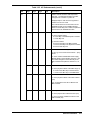
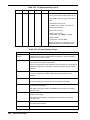
See the following example and Table 2-3 for device path formats for devices
that do NOT conform to EDD3.0 specification:
Example: SCSI cards and fixed disks installed on the PCI bus:
VenHw(Unknown Device:80)/HD(Part1,Sig6D5319DE)
Table 2-3. Formats for Devices Not Conforming to EDD3.0 Specification
Path Display
Description
VenHw(Unknown Device:80)
Example: The device does not conform to EDD3.0
specification.
80: a consecutive number (called a drive number) assigned
to the disk under the SCSI card by the system BIOS.
The drive numbers are as follows:
80 or higher: fixed disk drive
9F: DVD-ROM drive
HD(Part1,Sig6D5319DE)
SCSI disk drive information.
Checking Failure
When a failure is detected in the system, it can be checked in the Virtual System
Operator Panel (SOP) on the SP console. Virtual SOP provides the following
information:
!
Partition configuration of the system
!
Failure information.
For more information about Virtual SOP, see “Virtual SOP” in Chapter 3.
2-18 System Operation
Using the DVD-ROM Drive
A DVD-ROM drive comes standard in the Main Chassis.
The DVD-ROM drive supports DVD-ROM and CD-ROM media.
See the following sections for information about using DVD-ROM or
CD-ROM discs in the DVD-ROM drive.
! WARNING
Take care when inserting and removing DVD-ROM media.
To prevent injury, keep hands away from the tray when
ejecting or inserting the tray.
Inserting a Disc in the DVD-ROM Drive
Insert a DVD-ROM or CD-ROM disc in the DVD-ROM drive as follows (see
Figure 2-16).
1. Open the server door.
2. Press the Eject button on the DVD-ROM drive to eject the drive tray.
3. Place the disc on the tray, label facing up.
4. Press the Eject button on the DVD-ROM drive to insert the tray.
Removing a Disc from the DVD-ROM Drive
Remove a DVD-ROM or CD-ROM disc from the DVD-ROM drive as follows
(see Figure 2-16)
1. Open the server door.
2. Check that the drive access LED (orange) is off.
3. Press the Eject button on the DVD-ROM drive to eject the tray.
4. Remove the disc.
5. Press the Eject button on the DVD-ROM drive to insert the tray.
System Operation 2-19
DVD-ROM Drive
DVD-ROM/CD-ROM
Eject Button
Tray
Figure 2-16. Inserting/Removing a DVD-ROM/CD-ROM Disc
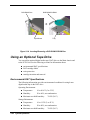
Using an Optional Tape Drive
You can add an optional digital audio tape (DAT) drive to the Main chassis and
to the PCIX Unit. See the following sections for information about:
!
environmental DAT specifications
!
DAT cartridge labels
!
write protection
!
cartridge insertion and removal.
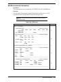
Environmental DAT Specifications
The following information provides environmental conditions for using 4-mm
digital audio tape in the DAT drive.
Operating Environment:
!
Temperature:
41 to 89.6°F (5 to 32°C)
!
Humidity:
20 to 60%, no condensation
!
Maximum wet bulb humidity:
78.8°F (26°C)
Storage Enironment:
!
Temperature:
41 to 113°F (5 to 45°C)
!
Humidity:
20 to 80%, no condensation
!
Maximum wet bulb humidity:
2-20 System Operation
78.8°F (26°C)
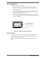
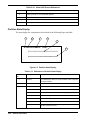
DAT Cartridge Labels
Use the following labeling information:
!
Place labels securely on the DAT cartridge in the position shown in
Figure 2-17. Be sure to write the start date of DAT cartridge use on the
attached Index label.
!
If you need to change the contents for the DAT, replace the label with a
new one. (Do not erase the label contents.) Be sure to remove the old
label before attaching the new label.
!
If you use a label other than the specified INDEX label, be sure the label
size is correct, the label can be easily replaced, and the label doesn’t leave
adhesive after removal.
NEC
Figure 2-17. Digital Audio Tape Label Positions
Write Protection
You can protect written data on the audio digital tape from being erased. To
protect the data, open the write protect slider on the label side of the digital
audio tape cartridge (see Figure 2-18).
To write or overwrite data on the digital audio tape, close the write protect
slider.
System Operation 2-21
Figure 2-18. Write Protection Slider on the DAT Cartridge
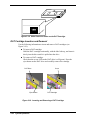
DAT Cartridge Insertion and Removal
Use the following information to insert and remove DAT cartridges (see
Figure 2-19).
!
To insert a DAT cartridge:
Hold the DAT cartridge horizontally, with the label side up, and insert it
slowly into the drive until it is pulled into the drive.
!
To remove a DAT cartridge:
Check that the access LED on the DAT drive is off (green). Press the
eject button on the DAT drive and carefully remove the cartridge.
DAT Drive
Eject Button
Cover
DAT Cartridge
Figure 2-19. Inserting and Removing a DAT Cartridge
2-22 System Operation
3
Service Processor
!
SP Console
!
OS Console
!
Virtual SOP
!
SP Command Console
!
SP Command Reference
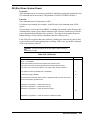
SP Console
The service processor (SP) in the Express5800/1080Xd main chassis provides the
interface for system management and RAS functions. The SP is on the service
processor and clock (ISP-C) board.
The following sections describe:
!
SP console connections
!
Console operations
!
Console status and login authentication
!
Login and Main Menu.
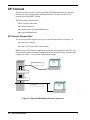
SP Console Connections
The service processor supports two types of console connections (see Figure 3-1):
!
serial (local console)
!
LAN via TCP port 5001 (LAN console).
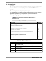
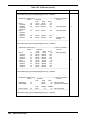
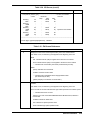
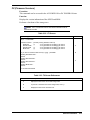
Both serial and LAN console connections provide the same operation. However, the
LAN console requires an initial configuration which can only be done using the local
console. See Table 3-1 for console configuration settings.
ISP-C Board
Null Modem Cable
Local
Console
Serial Connector 0
LAN Connector
TCP5001
LAN
Console
Figure 3-1. Express5800/1080Xd Console Connection
3-2 Service Processor
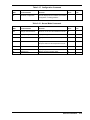
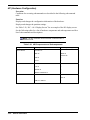
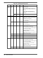
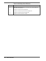
Table 3-1. Console Configuration Settings
Console Type
Configuration Item
Default Settings
Serial
Baud rate
9600
Data bit length
8
STOP bit length
1
Parity bit
None
Flow control
RTS/CTS
TCP port (Do not use 21, 23. They are for
factory use.)
5001
IP address
10.1.1.1
Subnet mask
255.255.255.0
Gateway IP address
N/A
LAN
Note: The most effective connection method between the
Express5800/1000 Series and the Service Processor is by using a telnet utility.
Multiple instances of the telnet utility can be running at once, providing multiple
windows with which to monitor and control the system. These utilities also
provide logging features, which can be very useful in back-tracking system
settings and status reports. Be sure to set VT100 emulation mode.
Console Operations
You can use the consoles to:
!
Operate the service processor using SP commands
!
Redirect the operating system (BIOS) serial console (in main chassis)
!
Display the Virtual SOP (Virtual System Operator Panel).
Console Status and Login Authentication
To use the consoles, you must first log into the service processor. When you log into the
service processor, the iSP Main Menu appears.
From the iSP Main Menu, you can switch to one of the following functions:
!
Virtual SOP – displays the system operating state for each partition with periodic
updates.
!
OS Console – redirects the serial input/output for the operating system (including
BIOS).
!
SP Command Console – allows you to monitor service processor output
messages required for system operation and maintenance and to enter commands
for the service processor. The SP Command Console lets you run commands
required for system operation.
Service Processor
3-3
Table 3-2 lists the login account and login password default values for entering the
Main Menu and using menu functions.
Table 3-2. Login Account and Password Defaults
Login Type
Defaults
Login Account
spfw
Login Password
nec
Note: Only one connection to the OS Console per partition, up
to five connections to the Virtual SOP in the entire system, and only
one prime connection to the SP Command Console in the entire
system can be made simultaneously. If LAN is used, additional SP
Command Consoles can be attached using hubs, but they will be in
monitor mode only, and commands can be entered only via the
prime connection.
See Figure 3-2 for a diagram of using console modes.
3-4 Service Processor
Ser ia l Con sole
TCP -5001
n ot Ava ila ble
n ot Con n ect ed
P r ess E SC Key
Con n ect TCP 5001
Select E xit
Select E xit
iSP login P rompt
Login
P a ssword Requ ir ed
Ma in Men u
P r ess ^ B Key
P r ess ^ B Key
P r ess ^ B Key
Select SOP
Vir tu al SOP
Select SP
SP Com ma n d
Select OS
OS Console
Norma l Mode
Figure 3-2. Express5800/1080Xd Console Mode Operations
Service Processor
3-5
Login and Main Menu
The initial state of a console connected to the service processor is the login wait state
with the login prompt displayed. When you enter the login account and password, the
iSP Main Menu appears.
The characters you enter for the login account and password are case-sensitive.
However, alphabetic characters you enter in the Main Menu are not case-sensitive. For
example, the lowercase letter “e” and the uppercase letter “E” are processed the same.
Table 3-3. Login and Main Menu Screen
Screen Image
Reference
Integrated Service Processor.
Cabinet-ID:xx, Location:y, State:ssssss
A
iSP login: spfw<ENTER>
iSP password: xxxxxxxx<ENTER>
B
Copyright (C) 2002 NEC Corporation, All Rights Reserved.
Welcome to Integrated Service Processor.
iSP FW version : 01.00 generated on 01/31/2002 19:20:33
C
iSP MAIN MENU
0) OS(BIOS) serial console of partition#0 (INITIALIZING )
1) OS(BIOS) serial console of partition#1 (RUNNING
)
V) Virtual System Operator Panel
S) iSP commands
E) Exit
D
DISCONNECTALL) disconnect all console connections
iSPyz>
3-6 Service Processor
E
Table 3-4. Login and Main Menu Screen References
Reference
Description
A
“xx “is the ID for identification of a cabinet in a system composed of multiple
cabinets.
(“xx” is the system number specified by the SU command.)
“y” indicates the installation location of the service processor - clock board with 0.
“ssssss” becomes “master.”
B
Entry for login account and password.
The password is not displayed.
C
Display of service processor firmware (iSP FW) version information.
D
Display of iSP Main Menu options.
The OS Console menu also displays a partition state summary.
E
Display of the iSP Main Menu selection prompt.
“y” indicates the service processor-clock board number for 0.
“z” becomes “m.”
Table 3-5. Main Menu Login Events and Operations
Event
Operation
The account or password is invalid.
Displays “incorrect” and then displays the login
prompt again.
The account or password is invalid three times
in a row.
Disconnects the session.
Left for 5 minutes in login or password prompt
state.
Displays “timeout” and then disconnects the
session.
A character not on the menu is entered.
Displays the menu again.
Left for 5 minutes in menu display state.
Displays “timeout” and then disconnects the
session.
0 – 3 selected.
Switches to the OS (BIOS) serial console
redirection.
S selected.
Switches to the SP Command Console.
V selected.
Switches to the Virtual SOP.
E selected.
Disconnects the session.
DISCONNECTALL selected.
Disconnects all connections with the service
processor except the current connection.
This operation occurs only in special situations
(such as the case where a connection with the
service processor was actually disconnected but
remains under service processor management due
to irregular access of a client to the service
processor; as a result, any further operation cannot
be performed).
After a DISCONNECTALL is selected,
authentication with Maintenance Mode is performed.
The number of simultaneous connections
allowed for the selected menu is exceeded.
Displays “N connections to the selected mode are
already established. Try it later.” Displays the Main
Menu again.
Service Processor
3-7
OS (BIOS) Console
When you select the OS (BIOS) Console on the iSP Main Menu, input/output is
redirected to the OS (BIOS) serial controller.
To return to the Main Menu, press ^B (CTRL+B).
The image displayed and the operation during redirection depend on the BIOS and OS
running in the partition; they are therefore not recognized by the service processor
firmware (iSPFW).
Table 3-6. OS (BIOS) Console Operation
Screen Image
Reference
iSP MAIN MENU
0) OS(BIOS) serial console of partition#0 (INITIALIZING )
1) OS(BIOS) serial console of partition#1 (RUNNING
)
V) Virtual System Operator Panel
S) iSP commands
E) Exit
DISCONNECTALL) disconnect all console connections
iSPyz> 0<ENTER>
*****redirection of serial console 0
*****
*****enter CTRL+B to quit
*****
:
:
:
:
:
<CTRL>+<B>
*****returned from serial console 0 redirection *****
A
B
C
D
E
Table 3-7. Login and Main Menu Screen References
Reference
Description
A
When you enter 0-3, the menu is redirected to the OS Console of the corresponding
partition.
B
The starting message of OS Console redirection is displayed.
C
“:” is input and output during the OS Console redirection depend on the OS and
BIOS.
D
Pressing ^B terminates the redirection of the OS Console.
E
A message is displayed to indicate the end of the redirection. Returns to Main Menu.
3-8 Service Processor
Table 3-8. OS (BIOS) Console Events and Operations
Event
Operation
^B (CTRL+B) is pressed.
Displays a message indicating the exit of the
session from the OS (BIOS) Console and then
returns to the Main Menu and prompt.
The SP command deletes the displayed
partition.
Displays a message indicating the exit of the
session from the OS (BIOS) Console and then
returns to the Main Menu and prompt.
Virtual SOP
When you select Virtual SOP (Virtual System Operator Panel) on the iSP Main Menu,
Virtual SOP appears. The Virtual SOP periodically refreshes the display of the state of
all the partitions.
To return to the Main Menu from the Virtual SOP, press ^B (CTRL+B).
Table 3-9. Virtual SOP Screen
Screen Image
Reference
iSP MAIN MENU
0) OS(BIOS) serial console of partition#0 (INITIALIZING )
1) OS(BIOS) serial console of partition#1 (RUNNING
)
2) OS(BIOS) serial console of partition#2 (STOPPED
)
3) OS(BIOS) serial console of partition#3 (FAULT
)
V) Virtual System Operator Panel
S) iSP commands
E) Exit
DISCONNECTALL) disconnect all console connections
iSPyz> V<ENTER>
A
----- Virtual System Operator Panel --------------------- 01/31/2001,19:30:20 ----xx 0 HW INITIALIZING
BIOS messages
SP messages
yyyyyy
xx 1 RUNNING
BIOS messages
SP messages
yyyyyy
xx 2 STOPPED
BIOS messages
SP messages
yyyyyy
xx 3 FAULT
BIOS messages
SP messages
yyyyyy
B
----- Enter CTRL+B to quit -----------------------------------------------------------------:
:
:
:
:
<CTRL>+<B>
C
D
Service Processor
3-9
Table 3-10. Virtual SOP Screen References
Reference
Description
A
When you enter “V,” the Virtual SOP appears.
B
Virtual SOP image is displayed.
C
The Virtual SOP is periodically displayed.
D
Pressing ^B terminates the Virtual SOP. Return to Main Menu.
Partition State Display
The state display for each partition is described in the following figure and table.
1
2
3
4
5
xx N sssssssssssssss cccccc
6
ttttttttttttttttttttttttttttttt
uuuuuuuuuuuuuuuuuuuuuuuuuuuuuuu
Figure 3-3. Partition State Display
Table 3-11. Reference to Partition State Display
Reference
No.
Display
Description
1
Numeral
ID for identifying a cabinet in a super scalable cluster composed
of multiple cabinets.
2
Numeral (0 – 3)
Partition number.
3
String
State of the partition.
POWER OFF
DC OFF state.
STOPPED
In DC ON state, has no failure, and is being stopped.
HW INITIALIZING
ISP is initializing the hardware. The BIOS has not started yet.
SW ININIALIZING
BIOS is initializing the system.
OS BOOTING
OS booting is in progress.
RUNNNG
BIOS has finished initialization of the system and the control
has been passed to the EFI.
3-10 Service Processor
Table 3-11. Reference to Partition State Display (cont’d)
Reference
No.
Display
Description
FAULT
Indicates that the BIOS has finished initialization of the system
and control has been passed to EFI.
SHUT DOWN
iSP is shutting down the hardware.
NOT CONFIGURED
Partition is not configured.
4
6-digit hexadecimal
Latest chassis code is sent from the BIOS or OS.
5
String
Displayed when any error code is sent from the BIOS. The code
has 4 figures. For information about the code, see the BIOS
section.
3 (cont’d)
Deleted at next system startup.
6
String
Displayed when any warning error message is sent from the
SP. The message is similar to the activity log. When the
message is long, the latter part of the message will be omitted.
Deleted at next system startup.
Service Processor
3-11
SP Command Console
When you select the iSP commands on the iSP Main Menu, the SP Command Console
appears. Initially, the SP Command Console is in Normal Mode for general operation.
You can switch to Maintenance Mode (which allows all operations) by using the CM
command.
To return to the Main Menu from the SP Command Console, press ^B (CTRL+B).
Table 3-12. SP Command Console Operation
Screen Image
Reference
iSP MAIN MENU
0) OS(BIOS) serial console of partition#0 (INITIALIZING )
1) OS(BIOS) serial console of partition#1 (RUNNING
)
2) OS(BIOS) serial console of partition#2 (STOPPED
)
3) OS(BIOS) serial console of partition#3 (FAULT
)
V) Virtual System Operator Panel
S) iSP commands
E) Exit
DISCONNECTALL) disconnect all console connections
iSPyz> S<ENTER>
A
:
:
B
:
:
:
C
<CTRL>+<B>
Table 3-13. SP Command Screen References
Reference
Description
A
When you enter S, the SP Command Console appears.
B
“:” indicates the monitoring of the SP command input and SP message output.
C
Pressing ^B exits the session from the SP Command Console and returns to the
Main Menu.
SP Command Console Buffer
SP Command Console output from the service processor might contain important
information, such as the cause of a system state change. With the LAN console,
however, you cannot monitor the console output from the end of iSP startup until the
LAN console connection is established. Therefore, the iSP has a function to save a
certain amount of message output in a buffer while the connection is being established
to the SP Command Console. About 1,000 lines of messages can be stored in this
buffer. The buffer stores the latest 1,000 lines of messages. You can use the ML
command to view the messages stored in the buffer.
3-12 Service Processor
SP Command Prompt
In SP command mode (Normal Mode or Maintenance Mode), one of the following
types of command prompt is displayed when you press the ESC key.
Interactive operations for each SP command and prompts for subcommand entry
depend on the SP command.
Table 3-14. SP Command Mode Prompts
Prompt
Description
ISPyz:-->
Command prompt in Normal Mode.
ISPyz:MNT>
Command prompt in Maintenance Mode.
SP Message Header
SP messages have a header in the formats listed in the following table.
No message header is added to the prompts and messages that appear during interactive
operations in each SP command.
Table 3-15. SP Message Header Formats
Message Header
Description
[iSPyz:INFO.cccc] string
Indicates an information message.
“cccc” is the ID assigned to each message.
“string” is the message body.
[iSPyz:WARN.cccc] string
Indicates a warning message.
[iSPyz:ERRORcccc] string
Indicates an error message.
Service Processor
3-13
SP Command List
The following table lists the SP commands by category.
Table 3-16. System Control Commands
NML
Mode
MNT
Mode
The iSP turns off the DC power of the
specified partition without notifying the SW
(OS) even if it is running.
X
X
Shut Down System Power
If the specified partition is in SO state, the iSP
only generates the SCI(POWBTN). Otherwise,
the iSP turns off the DC power directly.
X
X
DP
System Dump
The iSP generates the INIT signal to the
specified partition. SW(OS) will enter its dump
routine.
X
X
PC
Power Cycle
The iSP turns off the DC power of the
specified partition without notifying the
SE(OS) even if it is running, turns on the DC
power, initializes HW and hands off the control
to the BIOS.
X
X
RS
Cold Reset System
The iSP initializes the specified partition
without notifying the SW(OS) even if it is
running.
X
X
UP
Bring Up System
The iSP turns on the DC power of the
specified partition and initializes HW and
hands off the control to the BIOS. The BIOS
boots the operating system.
X
X
CMD
Command Name
Function
DF
Shut Down System Power
(override)
DN
DN /DP
DF
(on ly t r igger )
PC
Rea dy
DC OF F
SW r u n n in g
UP /P C
RS
DN /DF
DC ON
UP /P C/RS
N ot r u n n in g
Figure 3-4. System State Transitions and System Control Commands
3-14 Service Processor
Table 3-17. Configuration Command
CMD
Command Name
Function
HC
Hardware Configuration
The iSP displays and/or modifies the hardware
configuration, including partitions.
NML
Mode
X
MNT
Mode
X
Table 3-18. Normal Mode Commands
CMD
Command Name
Function
NML
Mode
MNT
Mode
CM
Change Command Mode
Enter into or exit from the maintenance mode.
X
X
DL
Display SP logs
Display the logs stored in iSP.
X
X
DT
SP Date and Time
Display the SP RTC (Real Time Clock) and set
it.
X
X
EN
Environmental Information
Display the environmental information such as
the power state and the temperature sensors.
X
X
FV
Firmware Version
Display the iSP FW version and BIOS version.
X
X
HE
Help
Display help information.
X
X
ML
Message Log
Display the iSP’s message buffer.
X
X
Service Processor
3-15
SP Command Reference
The following sections provide detailed information about SP commands.
The commands listed can be executed in Normal mode or Maintenance mode.
Basically, SP commands and subcommands are not case-sensitive. Any need for casesensitivity (for example, accounts and passwords) is described.
3-16 Service Processor
CM (Change Command Mode)
Execution:
This command can be executed in the AC POWER ON state or DC POWER ON state.
Entering Maintenance mode requires the entry of a password.
Function:
Changes from Normal mode to Maintenance mode. When the system is in Maintenance
mode, the Status LED on the front of the server is amber.
Note: The CM command can be executed in Normal mode or
Maintenance mode.
Table 3-19. CM Command Screen
Screen Image
Reference
iSPyz:---> cm<ENTER>
Password is needed to enter maintenance mode.
maintenance password : xxxxxxxx <ENTER>
incorrect.
maintenance password : xxxxxxxx <ENTER>
Command Mode was changed to maintenance mode.
A
B
Table 3-20. CM Screen References
Reference
A
Description
To switch from Normal mode to Maintenance mode, a password is required.
If you enter a wrong password, a message is displayed and the system waits for
another password entry. If you enter an incorrect password three times in a row, the
command terminates.
Passwords are case sensitive.
B
After the mode change to Maintenance mode is displayed, the command terminates.
Service Processor
3-17
DF (Shut Down System Power <override>)
Execution:
This command can be executed on a partition which is in one of the following states:
!
Automatic startup has completed or the UP command has been executed. (The
partition is in the DC POWER ON state)
!
The ON command has been executed. (The partition is in the DC POWER ON
state.)
Function:
This command turns off system power (DC).
This command turns off the system regardless of the operation state of the OS or BIOS
and without notifying either. (This corresponds to the power button override function of
a system that has a physical power button.)
Note: The DF command can be executed in Normal mode or
Maintenance mode.
Table 3-21. DF Screen
Screen Image
Reference
iSPyz:---> df<ENTER>
CAUTION:
System power will be turned off without any notice to the softwares even if they are
running.
Enter partition number (0-3/all/CR=exit) : all<ENTER>
A
Execute OK? (y/[n]) y<ENTER>
B
DF command was accepted. System power of all partitions will be turned off soon.
C
[iSPyz:INFO.ccc] partition 0 : power off sequence started.
[iSPyz:INFO.ccc] partition 1 : power off sequence started.
:
:
:
[iSPyz:INFO.ccc] partition 1 : power off sequence completed normally.
D
Table 3-22. DF Screen References
Reference
Description
A
Enter a partition number. If you select “all”, all the configured partitions become the
targets.
B
Displays the confirmation message. To continue, enter “y”.
C
Displays the DF command acceptance message.
D
Displays the state of the process running in the background.
3-18 Service Processor
DL (Display SP Logs)
Execution:
This command can be executed in the AC POWER ON state or DC POWER ON state.
Function:
This command displays the logs stored in the iSP. You can upload the logs as a file to
an FTP server.
The detailed log (HW fatal-iSP snapshot) is linked and managed with the activity log
entry. When the log storage area is full, a new activity log is written over the oldest
activity log. When this happens, you cannot refer to the oldest detailed log. You should
display the important log and store it as a screen log of the terminal software. Or,
upload the important log to the FTP server.
Note: The DL command can be executed in Normal mode or
Maintenance mode.
Table 3-23. DL Screen
Screen Image
Reference
iSPyz:---> dl<ENTER>
Log area status (03/01/2002 18:59:00 iSPFW R01.01):
Type
Entries Latest No. Earliest
Latest
--------------------- --------- -------------- ------------------------------- ---------------------------------activity
1000
404 01/31/2002 12:24:50 02/29/2004 13:54:12
HW fatal
16
0 01/31/2002 12:24:50 02/29/2004 13:54:12
HW recoverable
64
32 01/31/2002 12:24:50 02/29/2004 13:54:12
processor MCA
128
20 01/31/2002 12:24:50 02/29/2004 13:54:12
processor CMC
64
2 01/31/2002 12:24:40 02/29/2004 13:54:12
processor INIT
64
1 01/31/2002 12:24:40 01/31/2002 13:54:12
system dump
8
7 01/31/2002 12:24:40 02/29/2004 13:54:12
iSP snapshot
8
3 02/29/2004 15:34:51 02/29/2004 13:54:12
Display or FTP upload the activity logs? (d[isplay]/f[tp]/CR=exit) : f<ENTER>
IP of FTP server [default=10.0.0.2] (CR=skip) : 10.0.0.3<ENTER>
account [default=necuser] : necuser<ENTER>
password [default=********] : xxxxxxxx<ENTER>
file path : log/activity.log<ENTER>
connecting...
connected.
uploaded.
A
B
C
Display or FTP upload? (d[isplay]/f[tp]/CR=back) : d<ENTER>
D
Filter logs by partition? (a[ll]/0-3/CR=back) : a<ENTER>
E
Service Processor
3-19
Table 3-23. DL Screen (cont’d)
Screen Image
Reference
Filter logs by category?
a ... all
1 ... system control
2 ... system configuration
3 ... BIOS event
4 ... IPMI SEL
5 ... system init. error
6 ... SP event
(a/1-13/CR=back) : a<ENTER>
7 ... fatal error
8 ... recoverable error
9 ... dump event
11 ... proc. MCA event
12 ... proc. INIT event
13 ... proc. CMC event
select display mode (i[nteractive per page]/a[ll]/CR=back) : i<ENTER>
F
G
1023 10:30:32,12/31/2002 part.0--- CONTROL
system state S5.
1022 10:30:31,12/31/2002 part.0--- CONTROL
timeout. (Shutdown WDT)
1021 10:29:31,12/31/2002 part.0--- CONTROL
going to system state S5.
1020 10:29:30,12/31/2002 part.0--- IPMISEL
H
01234567 89abcdef 01234567 89abcdef
1019 10:29:29,12/31/2002 part.0--- IPMI
stop IPMI WDT.
1018 10:29:25,12/31/2002 part.0--- CONTROL
POWBTN# asserted.
1017 10:20:00,12/31/2002 part.-1-- HR(012)
ATT1(CELL2:Memory SBE, addr=0020304050607080, ROW25)
action? (h=help/CR=next) : h<ENTER>
h : help
l : latest entry
p : previous page
q : quit
<nnnn>
<hh:mm:ss,MM/DD/YYYY>
d <nnnn>
a <nnnn>
f <nnnn>
r : refresh
o : oldest entry
n : next page
: jump to the entry which is numbered nnnn.
: search the first entry after specified time.
: display detailed log dump if present.
: display detailed log analysis if present.
: ftp detailed log data if present.
action? (h=help/CR=next) : d 1017<ENTER>
***** LOG DUMP START *****
:
:
:
***** LOG DUMP END *****
action? (h=help/CR=next) : a 1017<ENTER>
3-20 Service Processor
I
Table 3-23. DL Screen (cont’d)
Screen Image
Reference
***** LOG ANALYSIS RESULT *****
:
:
:
***** LOG ANALYSIS END *****
action? (h=help/CR=next) : q<ENTER>
J
Log area status (03/01/2002 18:59:00 iSPFW R01.01):
Type
Entries Latest No. Earliest
Latest
---------------------- ------------ ------------- ----------------------------- ------------------------------activity
1000
404
01/31/2002 12:24:50 02/29/2004 13:54:12
HW fatal
16
0
01/31/2002 12:24:50 02/29/2004 13:54:12
HW recoverable
64
32
01/31/2002 12:24:50 02/29/2004 13:54:12
processor MCA
128
20
01/31/2002 12:24:50 02/29/2004 13:54:12
processor CMC
64
2
01/31/2002 12:24:40 02/29/2004 13:54:12
processor INIT
64
1
01/31/2002 12:24:40 01/31/2002 13:54:12
system dump
8
7
01/31/2002 12:24:40 02/29/2004 13:54:12
iSP snapshot
8
3
02/29/2004 15:34:51 02/29/2004 13:54:12
Display or FTP upload the activity logs? (d[isplay]/f[tp]/CR=exit) : <ENTER>
DL command terminated.
Table 3-24. DL Screen References
Reference
Description
A
On the DL command MENU, select “a”.
B, D
Select whether to display all the activity logs or upload them to the FTP server.
(Uploading detailed logs individually is described later.)
C
This is an example of uploading to the FTP server.
E
If you choose to display, select a partition number first.
When you enter a partition number (0-3), only the events related to the partition can
be displayed. (In this case, events common to the partitions are included in the
display.)
If you select “all”, no filtering by partition number is done.
F
Select a category.
You can display only the events of the specified category.
If you select “all”, no filtering by category is done.
G
Select to display all the events at the same time or to prompt you every 25 lines.
H
This is an example of activity logs.
Service Processor
3-21
Table 3-24. DL Screen References (cont’d
Reference
I
Description
If you enter “h” in response to “action?”, Help for the action appears.
If you specify an activity log number, you jump to the log number.
If you specify the time, you jump to the oldest log after the specified time.
The log with the display of “XXX log was collected.” has a link to the detailed log.
The operations listed below are available to the log:
If you enter “d <nnnn>”, hexadecimal dump output of the detailed log is done.
If you enter “f <nnnn>”, the detailed log is uploaded to the FTP server.
If you enter “a <nnnn>”, the result of the analysis of the detailed log with analyzing
program is displayed. The detailed logs with program analysis are as follows:
HW fatal, HW recoverable, processor MCA, iSP snapshot.
J
3-22 Service Processor
If you enter “q” in response to “action?”, the display exits from the log display.
DN (Shut Down System Power)
Execution:
This command can be executed on a partition if Automatic startup has completed or the
UP command has been executed. (The partition is in the DC POWER ON state.)
Function:
This command turns off system power (DC).
If software is not running (for example, in the S0 state), this command turns off the
system.
If any software, such as the OS and BIOS, is running (for example, in the S0 state), this
command only reports a power button interrupt to the software, and the process for the
power button interrupt depends on the software. (The software may ignore the power
button interrupt, or may perform a shutdown and turn off the power.)
Even if the iSP recognizes that some software is running, the software may not be able
to process the power button interrupt due to stalling. In this case, use the DF command
to force the system to turn off.
Note: The DN command can be executed in Normal mode or
Maintenance mode.
Table 3-25. DN Screen
Screen Image
Reference
iSPyz:---> dn<ENTER>
System power will be turned off if the software (OS) is NOT running.
Only power button interrupt will be generated if the software (OS) is running.
If you want to turn off the system power in any system state, use DF command.
Enter partition number (0-3/all/CR=exit) : all<ENTER>
A
Execute OK? (y/[n]) y<ENTER>
B
DN command was accepted. System power of all partitions will be turned off or power
button interrupt will be generated soon.
C
[iSPyz:INFO.ccc] partition 0 : power button interrupt.
[iSPyz:INFO.ccc] partition 1 : power button interrupt.
[iSPyz:INFO.ccc] partition 2 : power off sequence started.
:
:
:
[iSPyz:INFO.ccc] partition 2 : power off sequence completed normally.
D
Service Processor
3-23
Table 3-26. DN Screen References
Reference
Description
A
Enter a partition number.
If you select “all,” all configured partitions become the targets.
B
Displays the confirmation message.
To continue, enter “y”.
Displays the command acceptance message.
The actual process runs in the background.
C
D
3-24 Service Processor
Displays the state of the process running in the background.
DP (System Dump)
Execution:
This command can be executed on a partition if Automatic startup has completed or the
UP command has been executed. (The partition is in the DC POWER ON state.)
Function:
This command generates a dump interrupt in the system.
The actual operation of the dump processing and the following system reset depend on
the software (OS or BIOS). This command only generates a dump interrupt.
Obviously, nothing happens if no software is running.
Note: The DP command can be executed in Normal mode or
Maintenance mode.
Table 3-27. DP Screen
Screen Image
Reference
iSPyz:---> dp<ENTER>
Dump button interrupt will be generated.
Enter partition number (0-3/all/CR=exit) : all<ENTER>
A
Execute OK? (y/[n]) y<ENTER>
B
DP command was accepted. Dump button interrupt will be generated soon.
C
[iSPyz:INFO.ccc] partition 0 : dump button interrupt.
[iSPyz:INFO.ccc] partition 1 : dump button interrupt.
:
:
:
D
Table 3-28. DP Screen References
Reference
Description
A
Enter a partition number.
If you select “all,” al configured partitions become the targets.
B
Displays the confirmation message.
To continue, enter “y”.
Displays the command acceptance message.
The actual process runs in the background.
C
D
Displays the state of the process running in the background.
Service Processor
3-25
DT (SP Date and Time)
Execution:
This command can be executed in the AC POWER ON or DC POWER state.
Function:
Displays and changes the time of the real-time clock built into the iSP.
This command only displays time in Normal Mode.
Note: The DT command can be executed in Normal mode or
Maintenance mode.
Table 3-29. DT Screen
Screen Image
Reference
iSPyz:---> dt<ENTER>
current iSP RTC : 19:20:57,01/31/2002 +09:00
syncronized with NTP server (10.20.30.40)
DT command terminated
A: In Normal Mode, the command terminates after displaying the current time.
3-26 Service Processor
A
EN (Environmental Information)
Execution:
This command can be executed in the AC POWER ON or DC POWER state.
Function:
Lists the states of the system’s detected temperature and fan errors, etc. The
components in the DC POWER OFF state are not supervised.
Note: The EN command can be executed in Normal mode or
Maintenance mode.
Table 3-30. EN Screen
Screen Image
Reference
iSPyz:---> en<ENTER>
---- Power Box/Bay Units -------------------------------------------------- 19:20:57,01/31/2002 ---state
DPS0
DPS1
DPS2
DPS3
DPS4 DPS5
PBAY00 ON
----PBAY01 ON
----* EXT PBAY10 ON
----ALARM
------------------------------------------------------------------------------------------------------------------------- Main Chassis FANs ---------------------------------------------------- 19:20:57,01/31/2002 ---CELL
FR0
FF0
FR1
FF1
ALARM
HIGH
HIGH
HIGH
XIC/XBR
FRL
ALARM
PCIV0
FM0
FRR
FR2
A
B
FF2
FM1
FM2
FM3
ALARM
---------------------------------------------------------------------------------------------------------------------Next page? (n[ext]/e[xit]/CR=next) : <ENTER>
C
---- CELL/XIC/XBR board DD-con/Temp alarm ---------------------- 19:20:57,01/31/2002 ---state
DD-con
Temp
CELL0
ON
* CELL1
OFF
ALARM
* CELL2
NORESP
* CELL3
OFF
ALARM
D
* XIC
OFF
ALARM
* XBR
NORESP
------------------------------------------------------------------------------------------------------------------------- PCIX-BOX DD-con/Temp/FAN alarm ------------------------------ 19:20:57,01/31/2002 ---state
DD-con
Temp
FAN
Local/Remote
* PCIX0(V) ON
ALARM
--* PCIX1(F) OFF
ALARM
ALARM
Remote
* PCIX2(F) ON
--ALARM
Local
* PCIX3(F) OFF
--ALARM
Remote
E
----------------------------------------------------------------------------------------------------------------------
Service Processor
3-27
Table 3-30. EN Screen (cont’d)
Screen Image
Reference
Previous/Next page? (p[revious]/n[ext]/e[xit]/CR=next) : <ENTER>
---- Temperature (Celsius) [1/4] ------------------------------------------ 19:20:57,01/31/2002 ---current
threshold
comment
FAN
IPMI
ACPI
CELL0
46
45/ 50
60/ 62
80
PROC00
50
80/ 85 100/102
105
* PROC01
82
80/ 85 100/102
105
FAN High-speed
PROC02
PROC03
* CELL1
52
45/ 50
60/ 62
80
FAN High-speed
PROC10
PROC11
PROC12
70
80/ 85 100/102
105
* PROC13
103
80/ 85 100/102
105
reported to the
software
----------------------------------------------------------------------------------------------------------------------
F
Previous/Next page? (p[revious]/n[ext]/e[xit]/CR=next) : <ENTER>
---- Temperature (Celsius) [2/4] ------------------------------------------ 19:20:57,01/31/2002 ---current
threshold
comment
FAN
IPMI
ACPI
CELL2
49
45/ 50
60/ 62
80
FAN High-speed
PROC20
52
80/ 85 100/102
105
PROC21
53
80/ 85 100/102
105
PROC22
54
80/ 85 100/102
105
PROC23
55
80/ 85 100/102
105
CELL3
46
45/ 50
60/ 62
80
PROC30
52
80/ 85 100/102
105
PROC31
53
80/ 85 100/102
105
PROC32
54
80/ 85 100/102
105
PROC33
55
80/ 85 100/102
105
---------------------------------------------------------------------------------------------------------------------Previous/Next page? (p[revious]/n[ext]/e[xit]/CR=next) : <ENTER>
---- Temperature (Celsius) [3/4] ------------------------------------------ 19:20:57,01/31/2002 ---current
threshold
comment
FAN
IPMI
ACPI
* XBC0(XIC)
52
60/ 62
65 FAN High-speed
* XBC1(XBR)
61
60/ 62
65 reported to the software
FAN
WARN1 WARN2
* AIR FLOW IN
30
23/ 27
32
34 FAN High-speed
---------------------------------------------------------------------------------------------------------------------Previous/Next page? (p[revious]/n[ext]/e[xit]/CR=next) : <ENTER>
3-28 Service Processor
F
Table 3-30. EN Screen (cont’d)
Screen Image
Reference
---- Temperature (Celsius) [4/4] --------------------------------------- 19:20:57,01/31/2002 ---current
threshold
comment
FAN
IPMI
ACPI
PCIX0(V)
45
60/ 62
65
DBP
52
60/ 62
65
PCIX1(F)
IORB
DBP
PCIX2(F)
45
60/ 62
65
IORB
63
60/ 62
65 reported to the software
DBP
PCIX3(F)
45
60/ 62
65
IORB
52
60/ 62
65
DBP
---------------------------------------------------------------------------------------------------------------------Previous page? (p[revious]/e[xit]/CR=exit) : <ENTER>
Table 3-31. EN Screen References
Reference
A
Description
Displays the state of the Power Bay/Power Bay Unit in the chassis/cabinet.
If an alarm occurs, an asterisk (*) mark appears at the beginning of the line.
State
ON : Indicates that DC (48V) is supplied to the devices in the cabinet.
OFF: Indicates that DC (48V) is not supplied to the devices in the cabinet.
---: Indicates that no Power Bay Unit exists (not detected by the iSP).
DPSx
(blank): Indicates the normal state.
ALARM : Indicates an alarm state.
---: Indicates that no Distributed Power Supply Module exists
(not detected by the iSP).
((blank): Displays no indication on normal state.)
B
Displays the state of the Fan Units located in the Main Chassis and Expansion
Chassis.
If an alarm occurs, an asterisk (*) mark appears at the beginning of the line.
The Fan Units for the CELLV Board have high rotation speed and low rotation speed.
-- : Indicates that it does not exist.
(blank): In the case of XIC Board/XBR Board/PCIV Mother Board, indicates a
normal state.
ALARM: Indicates an alarm state.
low: Indicates low-speed operation state.
HIGH: Indicates high-speed operation state.
Service Processor
3-29
Table 3-31. EN Screen References (cont’d)
Reference
Description
C
When you press ENTER, the next page is displayed
D
Displays an alarm state for the DCDC converter on the CELLV Board/XIC/XBR Board
in the Main Chassis and Expansion Chassis.
If an alarm occurs, an asterisk (*) mark appears at the beginning of the line.
E
Displays an alarm state for the DCDC converter/fan/temperature of the PCIX Unit
and PCIV (Core Module).
If an alarm occurs, an asterisk (*) mark appears at the beginning of the line.
For information on the Fan Unit in the PCIV (Core Module), refer to B.
F
Displays the temperature detected by the board/unit temperature sensor.
If an alarm occurs, an asterisk (*) mark appears at the beginning of the line.
Also displays the threshold values hard-coded in iSPFW.
"FAN" indicates the threshold values for high-speed and low-speed fan rotation.
"IPMI" indicates the threshold values at which a report is sent to the software via the
IPMI interface.
" ACPI " indicates the threshold values at which a report is sent to the software via
the ACPI interface.
3-30 Service Processor
FV (Firmware Versions)
Execution:
This command can be executed in the AC POWER ON or DC POWER ON state.
Function:
Displays the version information of the iSPFW and BIOS.
Performs a checksum of the storage area.
Note: The FV command can be executed in Normal mode or
Maintenance mode.
Table 3-32. FV Screen
Screen Image
Reference
iSPyz:---> fv<ENTER>
Firmware Versions : (currently running firmware is Rxx.xx)
iSP BOOT
(*)
: xx.xx generated on mm/dd/yyyy hh:mm:ss
iSP FW bank0
: xx.xx generated on mm/dd/yyyy hh:mm:ss
iSP FW bank1
(*)
: xx.xx generated on mm/dd/yyyy hh:mm:ss
BIOS bank
(*)
: xx.xx generated on mm/dd/yyyy hh:mm:ss
A
Do you want to check the flash memory? (y/[n]) : y<ENTER>
B
checking iSP BOOT bank...
passed.
checking iSP FW bank0...
passed.
checking iSP FW bank1...
passed.
checking BIOS bank...
passed.
C
FV command terminated.
Table 3-33 FV Screen References
Reference
Description
A
Displays the state of the current FW storage area.
B
To perform a checksum test of the storage area, enter “y”.
C
Displays the state of the checksum test.
Service Processor
3-31
HC (Hardware Configuration)
Execution:
Conditions for executing subcommands are described in the following subcommand
table.
Function:
Displays and changes the configuration information of the hardware.
Displays and changes the partition settings.
See Table 3-38, “HC – ALL Display Screen” for an example of the HC display screen.
See the following tables for a list of hardware components and subcomponents and for a
list of subcommands and descriptions.
Note: The HC command can be executed in Normal mode or
Maintenance mode.
Table 3-34. HW Components and Subcomponents
Component
Subcomponent (1)
Subcomponent (2)
CELLV Board
Processor x4
--
MMC x2
ROW x8
CACHE x8
TAG x8
--
CXI x2
--
CXI x4
--
1.6G x4
--
MOVER x2
--
SERIAL CONSOLE x4
--
IOR
1.6G x2
XIC Board
PCIV/PCIX Unit
IOC x2
GXB x4 or GXB x2
3-32 Service Processor
--
Table 3-35. HC Subcommands
cmd
arg1
arg2
arg3
arg4
Description
help
-
-
-
-
Displays the list of subcommands.
This command can be executed in the AC
POWER ON or DC POWER ON state.
quit
exit
-
-
-
-
Exits from the HC command.
Before an exit, the check subcommand is
automatically executed.
This command can be executed in the AC
POWER ON state or DC POWER ON state.
disp
-
-
-
-
Used to display states.
Displays Help for “disp” when the argument is
omitted or an error exists.
This command can be executed in the AC
POWER ON or DC POWER ON state.
all
-
-
-
Displays all the states.
part
-
-
-
Displays the following partition division
information for each partition:
• State summary
• Physical CELLV Board number and logical
CELLV Board number
• Physical IOR chip number and logical IOR chip
number.
main
-
-
-
Displays the state summary of the system
configuration.
cellx
-
-
-
Displays the state of the CELLV Board.
“x” is the physical CELLV Board number (0-3).
mmcxy
-
-
-
Displays the detailed state of the ROW under
control of the MMC specified by “xy”.
“x” is the physical CELLV Board number (0-3) on
which MMC is installed.
“y” is the MMC number (0-1) in the CELLV
Board.
tagx
-
-
-
Displays the detailed state of the TAG.
“x” is the physical CELLV Board number (0-3) on
which TAG is installed.
xbcx
-
-
-
Displays the state of the XBC chip.
“x” is the physical XBC chip number (0-1).
Service Processor
3-33
Table 3-35. HC Subcommands (cont’d)
cmd
arg1
arg2
arg3
arg4
Description
disp
(cont’d)
pcixx
-
-
-
Displays the state of the PCIV/PCIX Unit.
“x” is the DGI/I2C cable port number (0-3) from
the iSP-C Board to the PCIV/PCIX Unit.
IOR0 is installed on the XIC Board. But the
IOR0 is displayed with the PCIX0(V) to realize
the same operation as the PCIX Unit.
pbayxy
-
-
-
Displays the state of the Power Bay/Power Bay
Unit.
“x” is the chassis number.
0: Power Bay in the Main/Expansion Chassis
1: Power Bay Unit
“y” is the ID number.
0 for the Power Bay in the Main Chassis
1 for the Power Bay in the Expansion Chassis
0 for the Power Bay Unit
attach
-
-
-
-
Used to associate partition numbers to CELLV
Boards and IORs.
The number of CELLV Boards in a partition
must be the same or greater than the number of
IORs.
Displays Help for “attach” when the argument is
omitted or an error is made.
This subcommand can be executed in the DC
POWER OFF state of the partition.
When the online configuration and
deconfiguration function is released, this
restriction will be relieved.
cellx
n
m
-
Associates the CELLV Board having the
physical number x with the logical CELLV Board
number m of partition n. (m: The number
recognizable by the BIOS and software.)
This command can also be used to change a
logical CELLV Board number if it has already
been associated.
Each logical CELLV Board number must be
unique among the CELLV Boards.
You cannot change the logical number of the
CELLV Board in the online state.
3-34 Service Processor
Table 3-35. HC Subcommands (cont’d)
cmd
arg1
arg2
arg3
arg4
Description
attach
(cont’d)
iorx
n
m
p
Associates the IOR having the physical number
x with the logical IOR number m of partition n.
(m: The number recognizable by the BIOS and
software.)
“p” (0-9) sets the priority.
Indicates which IOR is used with a higher
priority if the number of normal CELLV Boards is
smaller than the number of normal IORs due to
CELLV Board failure in the partition. (Smaller
values have a higher priority, and the IORs with
larger values get isolated one by one. If the
priority number is the same, the one with a
smaller physical IOR number has a higher
priority.)
This command can be used to change the
logical IOR number and priority if it has been
already associated.
The logical IOR number must be unique within
the partition.
You cannot change the logical IOR number or
priority of the IOR which is in the online state.
"Priority 0" is allowed one time for one partition
and a Basic I/O Board must be connected. If
any failure occurs in this IOR, the partition
cannot be started.
The IOR0 must have priority 0.
detach
-
-
-
-
Used to cancel the associations between
partition numbers and CELLV Boards/IORs.
You cannot detach any component that is in the
online state.
The number of CELLV Boards in a partition
must be greater than or equal to the number of
IORs.
Displays Help of “detach” when the argument is
omitted or an error is made.
cellx
-
-
-
Disassociates the CELLV Board having the
physical number x from the currently associated
partition.
iorx
-
-
-
Disassociates the IOR having the physical
number x from the currently associated partition.
Service Processor
3-35
Table 3-35. HC Subcommands (cont’d)
cmd
arg1
arg2
arg3
arg4
Description
swap
-
-
-
-
Used to swap a CELLV Board with another
CELLV Board while the software is operating.
This subcommand is not supported at
present.
(This is not a combination of “attach” and
“detach”. The process dedicated for “swap” is
executed.)
Displays Help for “swap” when the argument is
omitted or an error is made.
This subcommand can be executed on the
partition in the DC POWER ON state. An
execution of “swap” on the partitions requires
the online configuration and de-configuration
function of the OS.
cellx
celly
-
-
Swaps the operating CELLV Board having the
physical number x with the CELLV Board having
the physical number y.
No partition must be associated with CELLVy.
When the swap is complete, CELLVx is
disassociated from the partition and CELLVy is
associated to the partition.
The logical CELL Board number is transferred
from CELLVx to CELLVy.
smem
-
-
-
-
This subcommand is not supported at
present.
Used to specify the size of the shared memory
of the partition.
Displays Help for “smem” when the argument is
omitted or an error is made.
This subcommand can be executed on the
partition in the DC POWER OFF state.
n
mmm
-
-
Specifies the size of the shared memory of
partition n in units of MB.
You cannot make any change to the partitions
currently in operation.
If the size is not a multiple of 128 MB, it is
rounded up.
3-36 Service Processor
Table 3-35. HC Subcommands (cont’d)
cmd
arg1
arg2
arg3
arg4
Description
add
-
-
-
-
Used to instruct the iSP to add components
manually. The management state of the iSP
changes from “nonexist” to “power-off”.
Displays Help for “add” when the argument is
omitted or an error is made.
This subcommand can be executed in the AC
POWER ON state or DC POWER ON state.
When the Power Bay Unit is added, all partitions
must be in the DC POWER OFF state.
pbayxy
-
-
-
Adds a Power Bay/Power Bay Unit.
“x” is the chassis number.
0: Power Bay in the Main/Expansion Chassis
1: Power Bay Unit
“y” is the ID number.
0 for the Power Bay in the Main Chassis
1 for the Power Bay in the Expansion Chassis
0 for the Power Bay Unit
dpsxyz
-
-
-
Adds DPS to the Power Bay/Power Bay Unit.
“x” and “y” are the same as described in “pbay”
above.
“z” is the number of Distributed Power Supply
Module (DPS) in the Power Bay Unit (0-5). But
the number assigned in the Power Bay of the
Main Chassis and Expansion Chassis is 0,1 or
2.
xbcx
-
-
-
Adds a XBC chip.
“x” is the physical number of the XBC chip (0-1).
0: Used for the XBC chip on the XIC Board.
1: Used for the XBC chip on the XBR Board.
cellx
-
-
-
Adds a CELLV Board.
“x” is the physical number of the CELLV Board
(0-3).
0 or 3 is assigned to the CELLV Board in the
Main Chassis.
procxy
-
-
-
Adds a processor.
“x” is the physical CELLV Board number (0-3).
“y” is the processor installation location on the
CELLV Board (0-3).
Service Processor
3-37
Table 3-35. HC Subcommands (cont’d)
cmd
arg1
arg2
add
(cont’d)
pcixx
[bio]
arg3
arg4
Description
Adds a PCIV/PCIX Unit.
“x” is the DGI/I2C port number of the iSP-C
Board side (0-3).
If PCIV is specified, “0” must be specified to x.
If a PCiX Unit is specified, 1,2 or 3 must be
specified to x.
If the Basic I/O Board is attached, specify “bio”
as the second argument.
“bio” must be specified in the case of the
PCIX0(V).
IOR0 is installed on the XIC Board. But the
IOR0 is added when the PCIX0(V) is added to
realize the same operation as the PCIX Unit.
delete
-
-
-
-
Used to delete a component from the iSP
management. If you do not delete it from the
iSP management, the component which has
been physically removed will still be managed
as “INVISIBLE”.
You cannot delete any components in the DC
ON state (except Distributed Power Supply
Module (DPS)).
Displays Help for “delete” when the argument is
omitted or an error is made.
enable
<arg1>
-
-
-
<arg1> is the same as described in “add”.
-
-
-
-
Used to enable a component managed as
”DISABLE”.
Displays Help for ”enable” when the argument is
omitted or an error is made.
This subcommand can be executed in the DC
POWER OFF state of the partition that will use
the component.
When the online configuration and
deconfiguration function is released, this
restriction will be relieved.
pbayxy
-
-
-
Enables a Power Bay/Power Bay Unit.
“x” is the chassis number.
0: Power Bay in the Main/Expansion Chassis
1: Power Bay Unit
“y” is the ID number.
0 for the Power Bay in the Main Chassis
1 for the Power Bay in the Expansion Chassis
0 for the Power Bay Unit
3-38 Service Processor
Table 3-35. HC Subcommands (cont’d)
cmd
arg1
arg2
arg3
arg4
Description
enable
(cont’d)
xbcx
[all]
-
-
Enables the XBC chip.
“x” is the XBC chip number (0-1).
When the second argument is omitted, only the
XBC is enabled, and the states of any other
subcomponents do not change.
When “all” is specified as the second argument,
not only the XBC but also its subcomponents
become enabled.
cxix
-
-
Enables the CELLV Board interface part within
the XBC chip.
“x” is the interface part number (0-3).
The correspondence between CXI number of
the CELLV Board and the CXI number of the
XBC chip depends on the type of System Back
Plane.
System Back Plane (8-way):
CELL0 CXI0 - CXI0 XBC0
CELL0 CXI1 - CXI1 XBC0
CELL3 CXI0 - CXI2 XBC0
CELL3 CXI1 - CXI3 XBC0
When the CXI port within the XBC chip is
enabled, corresponding CXI port in the CELLV
Board is also enabled (and vice versa).
In the case of the System Back Plane (8-way),
refer to below.
When port 0 is enabled, port 1 is also enabled.
When port 1 is enabled, port 0 is also enabled.
When port 2 is enabled, port 3 is also enabled.
When port 3 is enabled, port 2 is also enabled.
ncix
-
-
Enables the NC interface part within the XBC
chip.
“x” is the interface number (0-1).
0: 1.6G cable port 0
1: 1.6G cable port 1
When the 1.6G port of XBC chip is enabled,
corresponding port in the NC chip/IOR chip is
also enabled (and vice versa).
moverx
-
-
Enables the MOVER part within the XBC chip.
“x” is the mover number (0-1).
Service Processor
3-39
Table 3-35. HC Subcommands (cont’d)
cmd
arg1
enable
(cont’d)
arg2
arg3
arg4
Description
serialx
-
-
Enables the serial controller part within the XBC
chip.
“x” is the serial controller number (0-3).
A partition requires a serial controller. When a
partition contains plural CELLV Boards, a serial
controller is selected from available serial
controllers automatically.
cellx
[all]
-
-
Enables the CELLV Board.
“x” is the physical CELLV Board number (0-3).
When the second argument is omitted, only the
CELLV Board is enabled, and the states of any
other subcomponents do not change. In this
case, operation is rejected if some required
components are disabled.
When “all” is specified as the second argument,
not only the CELLV Board but also its
subcomponents become enabled.
cxiy
-
-
Enables the XBC interface part within the
CELLV Board.
“y” is the interface part number (0-1).
For information on the relationship between the
CXI within the CELLV Board and the CXI within
the XBC chip, refer to “cxix” of “xbcx” in
“enable”.
procxy
-
-
-
Enables the Processor.
“x” is the physical CELLV Board number (0-3).
“y” is the Processor number (0-3) within the
CELLV Board .
mmcxy
[all]
-
-
Enables the MMC.
“x” is the physical CELLV Board number (0-3).
“y” is the MMC number (0-1) within the CELLV
Board.
When the second argument is omitted, only the
MMC is enabled, and the states of any other
subcomponents do not change.
When “all” is specified as the second argument,
not only the MMC but also its subcomponents
become enabled.
rowz
-
-
Enables the ROW.
“z” is the ROW number (0-3).
DIMM is not controlled individually.
DIMMs are automatically detected at the time of
startup.
3-40 Service Processor
Table 3-35. HC Subcommands (cont’d)
cmd
arg1
arg2
arg3
arg4
Description
enable
(cont’d)
mmcxy
(cont’d)
cachez
-
-
Enables the Cache.
tagx[sy]
-
“z” is the Cache number (0-7).
-
-
Enables the TAG.
“x” is the physical CELLV Board number (0-3).
“s” is either “e” (EVEN side) or “o” (ODD side).
“y” is the TAG number (0-3).
When “sy” is omitted, all the TAGs under the
CELLV Board specified by “x” become enabled.
pcixx
all
-
-
Enables the PCIV/PCIX Unit.
“x” is the DGI/I2C cable port number (0-3) of the
cable from the ISP-C Board to the PCIV/PCIX
Unit.
“all” must be specified as the second argument.
Then, not only the PCIV /PCIX Unit but also its
subcomponents become enabled.
IOR0 is installed on the XIC Board. But the
IOR0 is managed with the PCIX0(V) to realize
the same operation as the PCIX Unit.
iorx
[all]
-
-
Enables the IOR chip.
“x” is the physical IOR chip number (0-3).
When the second argument is omitted, only the
IOR chip is enabled, and the states of any other
subcomponents do not change.
When “all” is specified as the second argument,
not only the IOR chip but also its
subcomponents become enabled.
nciy
-
-
Enables the 1.6G interface part.
“y” is the interface number (0 only).
When the 1.6G port of IOR chip is enabled,
corresponding 1.6G port in the XBC chip/NC
chip is also enabled (and vice versa).
iocy
-
-
Enables the IOC.
“y” is the IOC number (0 or 1) within the IOR
Daughter Board.
Service Processor
3-41
Table 3-35. HC Subcommands (cont’d)
cmd
arg1
arg2
arg3
arg4
Description
enable
(cont’d)
gxbxy
-
-
-
Enables the GXB.
“x” is the DGI/I2C cable port number of the
cable from the iSP-C Board to the PCIV /PCIX
Unit (0-3).
“y” is the GXB number (0-3) within the
PCIV/PCIX Unit. PCIV does not have GXB
number (1).
disable
-
busA
|busB
-
-
Enables the busA side and busB side of GXB.
-
-
-
Used to disable a component manually.
Displays Help for “disable” when the argument
is omitted or an error is made.
If the component is online state, the component
can not be disabled.
<arg1>
<arg2>
-
-
<arg1> and <arg2> are the same as described
in “enable” above.
“all” cannot be specified.
online
-
-
-
-
Used to dynamically configure an offline
component while the OS is running.
This command functions only with the support of
the software (OS and BIOS).
This SP command may be unnecessary
depending on the OS.
Displays Help for “online” when the argument is
omitted or an error is made.
offline
cellx
-
-
-
Configures the CELLV Board for the OS.
xbcx
moverx
-
-
Configures the XBC chip’s mover for the OS.
iorx
-
-
-
Configures the IOR chip for the OS.
-
-
-
-
Used to dynamically disconfigure an online
component while the OS is running.
This command functions only with the support of
the software (OS and BIOS).
This SP command may be unnecessary
depending on the OS.
Display Help for “offline” when the argument is
omitted or an error is made.
<arg1>
3-42 Service Processor
<arg2>
-
-
Same as described in “online” above.
Table 3-35. HC Subcommands (cont’d)
cmd
arg1
arg2
arg3
arg4
Description
ncconn
-
-
-
-
Used to set connection information of the 1.6G
cable.
Displays Help for “ncconn” when the argument
is omitted or an error is made.
This subcommand can be executed when all
partitions are in the DC POWER OFF state.
xbcx
nciy
iors
ncit
iors
ncit
xbcx
nciy
Specifies the connection between the 1.6G port
with the port number y in the XBC chip with the
physical number x and the 1.6G port with the
port number t in the IOR chip with the physical
number s.
t must be (0).
ncdis
-
-
-
-
Used to disconnect the 1.6G cable.
Displays Help for “ncdis” when the argument is
omitted or an error is made.
This subcommand can be executed when all
partitions are in the DC POWER OFF state.
xbcx
nciy
-
-
Removes the connection of the 1.6G port with
the port number y in the XBC chip with the
physical number x.
It is linked to the disconnection of the
corresponding port (and vice versa).
iors
ncit
-
-
Removes the connection of the 1.6G port with
the port number t in the IOR chip with the
physical number s. t must be (0).
It is linked to the disconnection of the
corresponding port (and vice versa).
led
-
-
-
-
Used to turn on/off a component’s LED to
identify its location.
Displays Help for “led” when the argument is
omitted or an error is made.
For execution on XBC (XIC Board/XBR Board)
and CELLV Board, one of the partitions must be
in the DC POWER ON state.
For execution on the PCIX, no condition is
required.
For execution on the PCI slot, the superior GXB
must be in the online state.
xbcx
on|off
-
-
Turns on/off the LED of the XIC Board/XBR
Board.
“x” is specified as below.
0: XIC Board
1: XBR Board
Service Processor
3-43
Table 3-35. HC Subcommands (cont’d)
cmd
arg1
arg2
arg3
arg4
Description
led
(cont’d)
cellx
on|off
-
-
Turns on/off the LED of the CELLV Board.
“x” is the physical CELLV Board number (0-3).
pcixx
on|off
-
-
Turns on/off the LED of the PCIV/PCIX Unit.
“x” is the number of PCIV/PCIX Unit
(0-3).
When the PCIV is specified, all alarm LEDs are
turned on.
pcixx
slotnn
on|off
-
Turns on/off the LED of the PCI slot in the
PCIV/PCIX Unit. Slot number printed at the back
side of the Unit must be designated.
“x” is the number of PCIV/PCIX Unit
(0-3).
“nn” is the slot number printed at the back side
of the Unit.
gxbxy
busA|
slotn
on|off
busB
Turn on/off the LED of the PCI slot in the
PCIV/PCIX Unit according to physical control
number.
“x” is the PCIV/PCIX Unit number
(0-3).
“y” is the GXB number (0-3) in the PCIV /PCIX
Unit.
“n” is the slot number (0-3) in the unit of GXB
bus.
loc
fann
on|off
-
-
Turn on/off the LED of the Fan Unit in the Main
Chassis. “n” is the Fan Unit number.
-
-
-
-
Used to specify location information manually.
Displays Help for “loc” when the argument is
omitted or an error is made.
This subcommand can be executed when all
partitions are in the DC POWER OFF state.
main
d
-
-
Specifies the location of the Main Chassis.
“d” is the position of the lower edge of the
chassis from the bottom of the cabinet in
decimal (0-63) by using the EIA unit.
(1 EIA unit = 44.45mm)
3-44 Service Processor
Table 3-35. HC Subcommands (cont’d)
cmd
arg1
arg2
arg3
arg4
Description
loc
(cont’d)
pbayxy
d
h
-
Specifies the location and height of the Power
Bay Unit in the cabinet.
“x” is the unit ID number.
1: Power Bay Unit
0: Not allowed
“y” is the ID number. (0) must be specified.
“d” is the position of the lower edge of the unit in
decimal (0-63) by using the EIA unit.
(1 EIA unit = 44.45mm)
“h” is the height of the unit (3).
pcixx
c
d
Specifies the location and height of the PCIX
Unit in the cabinet.
“x” is the PCIX Unit number (1-3).
“c” must be (1).
“d” is the position of the lower edge of the unit in
decimal (0-63) by using the EIA unit.
(1 EIA unit = 44.45mm).
check
-
-
-
-
Checks the current configuration information
from the following points:
• Presence of units whose location information
is not entered
• Presence of “DISABLE” components
• Presence of “INVISIBLE” units
Configuration violating the installation
restrictions
Configuration with penalty in
performance/RAS.
This subcommand can be executed in the AC
POWER ON state or DC POWER ON state.
Service Processor
3-45
Table 3-35. HC Subcommands (cont’d)
cmd
arg1
arg2
arg3
arg4
Description
clear
mmcxy
rowz
-
-
Clears the memory bit error counters of ROW.
“x” is the physical CELLV Board number (0-3).
“y” is the MMC number (0-1) within the CELLV
Board.
“z” is the ROW number (0-3).
Each ROW has 3 counters. 3 counters are
cleared at the same time.
[Types of error counters]
• Single bit error counter:
Counts in the unit of DIMM in the ROW.
• Multi bit counter:
Counts in the unit of the ROW.
This subcommand can be executed in the AC
POWER ON state or DC POWER ON state.
Table 3-36. HC State Display Strings
Displayed String
Description
nonexist
Indicates that a component is defined as non-existent (i.e. the iSP manages a
component as if it does not exist).
INVISIBLE
The iSP manages a component as if it exists, but it does not exist when seen
from the iSP due to failure or other reasons.
Once it is recognized by the iSP (regardless of auto detection or manual setting),
it will be managed as if it exists unless you delete it explicitly using the “delete”
command.
power-off
Indicates that the power supply (DC) is OFF.
For some components, the power supply (DC) becomes ON when AC is
supplied.
power-on
Indicates that the power supply (DC) is ON.
For some components, it is overwritten by the following state display.
offline
Indicates that the power supply (DC) is ON and a component is not configured in
the software (OS or BIOS).
This applies to the CELLV Board, XIC/XBR Board, PCIV/PCIX Unit, and their
subcomponents.
online
Indicates that the power supply (DC) is ON and a component is configured in the
software (OS or BIOS).
This applies to CELLV Board, XIC/XBR Board, PCIV/PCIX Unit, and their
subcomponents.
master
This is valid only for the state display of the ISP-C Board. Always Indicates that
it is operating as the master.
enable
Indicates that the component itself is enabled (used for system operation).
3-46 Service Processor
Table 3-36. HC State Display Strings (cont’d)
Displayed String
Description
DISABLE
Indicates that the component itself is disabled (not used for system operation).
In this state, it is detached from the system manually with the “disable”
command.
DISABLE*
Indicates that the component itself is disabled (not used for system operation).
In this state, it is detached from the system due to failure of the component itself
or failure of the host interface.
It should not be configured in the system until the defective part is replaced.
DEG
Indicates that some subcomponents are in the DISABLE state.
Table 3-37. HC Help Screen
Screen Image
Reference
iSPyz:---> hcENTER>
iSP FW version is Rxx.xx.
HC> help<ENTER>
HC command help :
help
: print this message.
disp
: display current status.
smem
: set size of shared memory of a partition.
attach
: attach CELLs and IORs to a partition.
detach : detach CELLs and IORs from a partition.
swap
: swap CELLs in a partition.
add
: add a component.
delete
: delete a component.
enable : enable a component.
disable : disable a component.
online
: make a component online.
offline
: make a component offline.
ncconn : connect 1.6G ports each other.
ncdis
: disconnect 1.6G ports.
led
: turn on/off maintenance LED of a component.
loc
: set location info.
clear
: clear memory bit error counters.
check
: check illegal configuration.
quit
: quit from HC command prompt.
A
B
A: Displays Help for the HC command when you enter “help”.
B: Displays the list of HC commands.
Service Processor
3-47
Table 3-38. HC ALL Display Screen
Screen Image
Reference
iSPyz:---> hcENTER>
iSP FW version is Rxx.xx.
HC> disp all<ENTER>
==== Partitioning ================================= 19:20:23,01/31/2002 ===
part0(RUN )
CELL:01-- (01--) IOR:0--- (0---)
part1(INIT)
CELL:--2- (--2-)
IOR:-1-- (-0--)
part2(STOP)
CELL:---3 (---3)
IOR:--2- (--0-)
part3(----)
CELL:---- (----)
IOR:---- (----)
==================================================================
A
==== Summary (15/0/29+8F) ======================== 19:20:23,01/31/2002 ===
PBAY00 (loc=15/0/29+8F)
power-on enable
DEG
PBAY01 (loc=15/0/23+6F)
power-on enable
DEG
PBAY10 (loc=15/1/00+3F)
power-on enable
DEG
iSP0 (loc=15/0/29+8F/30)
XBC0 (loc=15/0/29+8F/08)
XBC1 (loc=15/0/23+8F/09)
CELL0 (loc=15/0/29+8F/00)
CELL1 (loc=15/0/29+8F/01)
CELL2 (loc=15/0/23+8F/02)
CELL3 (loc=15/0/23+8F/03)
master
offline
power-off
online
offline
online
power-off
------enable
DISABLE
enable
DISABLE
enable
enable
--DEG
DEG
DEG
part.0 (LCN=0)
part.0 (LCN=1)
part.1 (LCN=3)
part.2 (LCN=2)
B
PCIX0(V) (loc=15/0/23+8F) online enable
DEG
part.0 (LIN=0,PRI=0)
PCIX1(F) (loc=15/0/17+4F) offline enable
DEG
part.0 (LIN=1,PRI=5)
PCIX2(F) (loc=15/0/19+4F) online enable
DEG
part.1 (LIN=0,PRI=0)
PCIX3(F) (loc=15/-/-----)
power-off enable
DEG
part.2 (LIN=0,PRI=0)
==================================================================
---- CELL0 --------------------------------------------------------------------- 19:20:23,01/31/2002 --CELL0 (loc=15/0/29+8F/00)
online
enable
DEG
part.0 (LCN=2)
PROC00
offline
DISABLE --PROC01
online
enable
--PROC02
offline
DISABLE* --PROC03
nonexist.
MMC00
online
enable
DEG
MMC01
offline
enable
DEG
TAG0
--------- -------DEG
CXI0
--------- enable
----->XBC0 CXI0
CXI1
--------- disable
----->XBC1 CXI0
IOM port0
--------- ---------IOR0-IOC1
IOM port1
--------- ---------IOR0-IOC0
---- MMC00 -------------------------------------------------------------------- 19:20:23,01/31/2002 --MMC00
online enable
DEG
ROW0[DIMM00:01] 1024MB --------- enable
--SBE=000:000 MBE=000
ROW1[DIMM10:11] 1024MB --------- enable
--SBE=000:000 MBE=000
ROW2[DIMM20:21] 1024MB --------- DISABLE --SBE=000:000 MBE=000
ROW3[DIMM30:31] 1024MB --------- DISABLE --SBE=000:021 MBE=000
cache000
--------- enable
--cache001
--------- enable
--cache002
--------- enable
--cache003
--------- enable
--cache004
--------- DISABLE* --cache005
--------- enable
--cache006
--------- enable
--cache007
--------- DISABLE ---
3-48 Service Processor
C
D
Table 3-38. HC ALL Display Screen (cont’d)
Screen Image
Reference
---- MMC01 -------------------------------------------------------------------- 19:20:23,01/31/2002 --MMC01
ROW0[DIMM00:01] 512MB
ROW1[DIMM10:11] 512MB
ROW2[DIMM20:21] 1024MB
ROW3[DIMM30:31] 1024MB
cache010
cache011
cache012
cache013
cache014
cache015
cache016
cache017
offline
-------------------------------------------------------------------------------------------------
enable
enable
enable
DISABLE
DISABLE
enable
enable
enable
enable
DISABLE*
enable
enable
DISABLE
DEG
-------------------------
SBE=000:000 MBE=000
SBE=000:000 MBE=000
SBE=000:000 MBE=000
SBE=000:021 MBE=000
---- TAG0 ----------------------------------------------------------------------- 19:20:23,01/31/2002 --TAG0
--------- -------DEG
TAG0e0
--------- DISABLE --TAG0e1
--------- enable
--TAG0e2
--------- DISABLE* --TAG0e3
--------- enable
--TAG0o0
--------- enable
--TAG0o1
--------- DISABLE --TAG0o2
--------- enable
--TAG0o3
--------- enable
---
D
E
---- CELL1 --------------------------------------------------------------------- 19:20:23,01/31/2002 --:
:
:
---- XBC0 (XIC) --------------------------------------------------------------- 19:20:23,01/31/2002 --XBC0 (loc=15/0/29+8F)
online enable
DEG
CXI0
-------- enable
----->CELL0 CXI0
CXI1
-------- DISABLE* ----->CELL1 CXI0
CXI2
-------- enable
----->CELL2 CXI0
CXI3
-------- DISABLE* ----->CELL3 CXI0
1.6G port0
-------- enable
----->IOR0 port0
1.6G port1
-------- DISABLE* ----->IOR1 port0
MOVER0
-------- enable
--MOVER1
-------- DISABLE --SERIAL0
-------- used
--part.0
SERIAL1
-------- not used
--SERIAL2
-------- used
--part.1
SERIAL3
-------- disable
--part.2
F
---- XBC1 (XBR) -------------------------------------------------------------- 19:20:23,01/31/2002 --XBC1 (loc=15/0/23+8F)
online enable
DEG
CXI0
-------- enable
----->CELL0 CXI1
CXI1
-------- DISABLE* ----->CELL1 CXI1
CXI2
-------- enable
----->CELL2 CXI1
CXI3
-------- DISABLE* ----->CELL3 CXI1
1.6G port0
-------- enable
----->IOR2 port0
1.6G port1
-------- DISABLE* ----->IOR3 port0
MOVER0
-------- enable
--MOVER1
-------- DISABLE --SERIAL0
-------- used
--part.0
SERIAL1
-------- not used
--SERIAL2
-------- used
--part.1
SERIAL3
-------- disable
--part.2
Service Processor
3-49
Table 3-38. HC ALL Display Screen (cont’d)
Screen Image
---- PCIX0(V) ------------------------------------------------------------------ 19:20:23,01/31/2002 --IOR0 (loc=15/0/29+8F)
online enable
DEG part.0 (LIN=0,PRI=0)
1.6G port0
-------- enable
----->XBC0 port0
IOC00
-------- enable
DEG
IOC01
-------- enable
DEG
GXB00 (loc=15/0/29+8F)
-------- enable
--BUS-A
-------- enable
--BIO
BUS-B
-------- enable
--GXB01 (loc=--/-/--+--)
-------- nonexit
--BUS-A
-------- nonexit
--BUS-B
-------- nonexit
--GXB02 (loc=15/0/29+8F)
-------- enable
--BUS-A
-------- enable
--BUS-B
-------- enable
--GXB03 (loc=15/0/29+8F)
-------- enable
--BUS-A
-------- enable
--BUS-B
-------- enable
---
Reference
G
---- PCIX2(F) ------------------------------------------------------------------ 19:20:23,01/31/2002 --IOR2 (loc=15/0/13+4F)
offline enable
DEG part.0 (LIN=2,PRI=9)
1.6G port0
-------- enable
----->XBC2 port0
IOC20
-------- enable
DEG
IOC21
-------- enable
DEG
GXB20 (loc=15/1/13+4R)
-------- enable
--BUS-A
-------- enable
--BIO
BUS-B
-------- enable
--GXB21 (loc=15/1/13+4R)
-------- enable
--BUS-A
-------- enable
--BUS-B
-------- enable
--GXB22 (loc=15/1/13+4R)
-------- enable
--BUS-A
-------- enable
--BUS-B
-------- enable
--GXB23 (loc=15/1/13+4R)
-------- enable
--BUS-A
-------- enable
--BUS-B
-------- enable
--:
:
:
---- PBAYs --------------------------------------------------------------------- 19:20:23,01/31/2002 --PBAY00 (loc=15/0/23+8F)
power-on enable
DEG
DPS000
DPS001
INVISIBLE
DPS002
PBAY01 (loc=15/0/23+8F)
power-on enable
DEG
DPS010
DPS011
INVISIBLE
DPS012
ALARM
PBAY10 (loc=15/1/00+3F)
power-on enable
DEG
DPS100
DPS101
DPS102
DPS103
INVISIBLE
DPS104
ALARM
DPS105
3-50 Service Processor
H
Table 3-39. HC ALL Display Screen References
Reference
Description
A
Displays the partition configuration information.
B
Displays the configuration information of the units/devices in the Main Chassis.
C
Expands the CELLV Board and displays the configuration information.
D
Expands the MMC and displays the configuration information.
E
Expands the TAG and displays the configuration information.
F
Expands the XIC/XBR Board and displays the configuration information.
G
Expands the PCIV/PCIX Unit and displays the configuration information.
H
Expands the Power Bay/Power Bay Unit and displays the configuration information.
Service Processor
3-51
HE (Help)
Execution:
This command can be executed in the AC POWER ON or DC POWER ON state.
Enter HELP or HE to execute this command.
Function:
Displays the list of commands.
The list of commands differs for Normal Mode and Maintenance Mode.
Note: The HE command can be executed in Normal mode or
Maintenance mode.
Table 3-40. HE Display Screen
Screen Image
Reference
iSPyz:---> heENTER>
iSP commands :
System Control (both customers and maintenance persons)
DF – Shut down the system (override)
DN – Shut down the system
DP – Generate the system dump interrupt
PC – Power cycle
RS – Cold reset the system
UP – Bring up the System
Configuration (both customers and maintenance persons)
HC – Hardware configuration and partitioning
Miscellaneous (both customers and maintenance persons)
CM – Change SP command mode
DL – Display SP logs
DT – SP Date and Time
EN – Display environmental information
FV – Display firmware versions
HE – Display this help
ML – Display message log
HE command terminated.
A: Displays help for Normal Mode commands.
3-52 Service Processor
A
ML (Message Log)
Execution:
This command can be executed in the AC POWER ON or DC POWER ON state.
Function:
Displays the contents of the iSP message buffer.
(The message output generated in the display operation of the message buffer is not
stored in the message buffer.)
Note: The ML command can be executed in Normal mode or
Maintenance mode.
Table 3-41. ML Display Screen
Screen Image
Reference
iSPyz:---> mlENTER>
ML command displays iSP’s message log buffer.
Select interactive mode? (i[nteractive per page]/a[ll]/CR=exit) : i<ENTER>
***** start of message logs *******************************************
xxxxxxxxxxxxxxxxx
xxxxxxxxxxxxxxxxxxxxxxxxxxxxxxxxxxxxxx
:
:
:
xxxxxxxxxxxxxxxxxxxxxx
Next ? (n[ext]/CR=exit) : n<ENTER>
xxxxxxxxxxxxxxxxxxxx
xxxxxxxxxxxxxxxxxxxxxxxxxxxxxxxxxxxxxxxxxxxxxx
:
:
:
xxxxxxxxxxxxxxxxxxxxxxxxxxx
Previous/Next ? (p[revious]/n[ext]/CR=exit) : n<ENTER>
xxxxxxxxxxxxxxxxxxxxxxxxxxx
xxxxxxxxxxxxxxxxxxxxxxxxxxxxxxxxxxxxxx
:
:
:
xxxxxxxxxxxxxxxxxxx
Previous ? (p[revious]/CR=exit) : <ENTER>
***** end of message logs *********************************************
ML command terminated.
A
B
C
D
E
Service Processor
3-53
Table 3-42. ML Display Screen References
Reference
Description
A
Select either the mode that prompts you every page or the mode that displays the
entire buffer at the same time.
B
Prompts you to respond if the next page exists.
C
Prompts you to respond if the previous and next pages exist.
D
Prompts you to respond if the previous page exists.
E
Displays the command termination message.
3-54 Service Processor
PC (Power Cycle)
Execution:
This command can be executed on a partition in the following state:
!
Automatic startup completed
!
Execution of UP command.
The partition is in a DC POWER ON state.
Function:
Turns off the power (DC) of the system, and then turns it on again to start up the
system.
Note: This command turns off the system regardless of the
operation state of the OS or BIOS and without notifying either.
Note: The PC command can be executed in Normal mode or
Maintenance mode.
Table 3-43. PC Display Screen
Screen Image
Reference
iSPyz:---> pcENTER>
CAUTION:
System power will be turned off without any notice to the softwares even if they are
running.
Enter partition number (0-3/all/CR=exit) : all<ENTER>
A
Execute OK? (y/[n]) y<ENTER>
B
PC command was accepted. System power of all partitions will be turned off soon and
then will be turned on.
C
[iSPyz:INFO.ccc] partition 0 : power off sequence started.
[iSPyz:INFO.ccc] partition 1 : power off sequence started.
:
[iSPyz:INFO.ccc] partition 1 : power off sequence completed normally.
:
[iSPyz:INFO.ccc] partition 0 : power on sequence started.
[iSPyz:INFO.ccc] partition 1 : power on sequence started.
:
[iSPyz:INFO.ccc] partition 1 : power on sequence completed normally.
:
[iSPys:INFO.ccc] partition 1 : handed off the control to BIOS.
D
Service Processor
3-55
Table 3-44. PC Display Screen References
Reference
A
Description
Enter a partition number
If you select “all”, all the configured partitions become the targets.
However, the partitions that are already OFF do not become the targets
B
Displays the confirmation message.
To execute, enter “y.”
C
Displays the PC command acceptance message.
The actual process runs in the background.
D
3-56 Service Processor
Displays the state of the process running tin the background.
RS (Cold Reset System)
Execution:
This command can be executed on a partition in the following state:
!
Automatic startup completed
! Execution of UP command.
The partition is in a DC POWER ON state.
Function:
Performs a cold reset of the system.
Note: This command performs a reset without any notification
even if the OS (BIOS) is running.
Note: The RS command can be executed in Normal mode or
Maintenance mode.
Table 3-45. RS Display Screen
Screen Image
Reference
iSPyz:---> rsENTER>
CAUTION:
System will be reset without any notice to the softwares even if they are running.
Enter partition number (0-3/all/CR=exit) : all<ENTER>
A
Execute OK? (y/[n]) y<ENTER>
B
RS command was accepted. All partitions will be resetted soon.
C
[iSPyz:INFO.ccc] partition 0 : initializing HW.
[iSPyz:INFO.ccc] partition 1 : initializing HW.
:
:
:
[iSPyz:INFO.ccc] partition 0 : handed off the control to BIOS.
[iSPyz:INFO.ccc] partition 1 : handed off the control to BIOS.
D
Table 3-46. RS Display Screen References
Reference
A
Description
Enter a partition number
If you select “all”, all the configured partitions become the targets.
However, the partitions that are already OFF do not become the targets
B
Displays the confirmation message.
To execute, enter “y.”
C
Displays the RS command acceptance message.
The actual process runs in the background.
D
Displays the state of the process running tin the background.
Service Processor
3-57
UP (Bring Up System)
Execution:
This command can be executed on a partition in the DC POWER OFF state.
Function:
Turns on the power (DC) of the system, initializes the hardware, and then starts up the
BIOS.
Whether the operating system starts up depends on the BIOS/EFI settings.
Note: The UP command can be executed in Normal mode or
Maintenance mode.
Table 3-47. UP Display Screen
Screen Image
Reference
iSPyz:---> upENTER>
This command will bring up the specified partition.
Enter partition number (0-3/all/CR=exit) : all<ENTER>
A
Execute OK? (y/[n]) y<ENTER>
B
UP command was accepted. All partitions will run soon.
C
[iSPyz:INFO.ccc] partition 0 : power on sequence started.
[iSPyz:INFO.ccc] partition 1 : power on sequence started.
:
[iSPyz:INFO.ccc] partition 1 : power on sequence completed normally.
:
[iSPys:INFO.ccc] partition 1 : handed off the control to BIOS.
Table 3-48. RS Display Screen References
Reference
A
Description
Enter a partition number
If you select “all”, all the configured partitions become the targets.
B
Displays the confirmation message.
To execute, enter “y.”
C
Displays the UP command acceptance message.
The actual process runs in the background.
D
3-58 Service Processor
Displays the state of the process running in the background.
D
4
BIOS Setup
!
Setup Overview
!
Menu Tree
!
Menu Options and Settings
!
BIOS Virtual DIP Switch
!
PCI Online Maintenance (PCI Hot Plug)
!
HBB Configuration Submenu Precaution
Setup Overview
See the following sections for a description of BIOS Setup, when you need to change
BIOS settings, and how to start and use BIOS Setup.
What is Setup?
Setup is a utility that allows you to set up the system hardware. Settings for PCI
Bridges and devices that connect with the system are included. Setup is incorporated in
the BIOS, and can be executed without any dedicated utility disk.
In most cases, you do not have to use Setup because the settings for it have already been
optimized prior to the system being shipped. However, you can use Setup for the cases
described in the next section.
When You Should Change the Settings
Start Setup and change the settings in the following cases:
!
Some setting errors exist.
!
Settings of CMOS and/or NVRAM are cleared.
Two types of NVRAM exist: NVRAM for BIOS and NVRAM for SPFW. The
NVRAM above is the one for the BIOS.
!
Adding or deleting a boot device.
!
The BIOS version has changed.
!
The Host Bus Bridge (HBB) configuration has changed.
You can also perform the following:
!
Set and/or change the date/time setting.
!
Set and/or change the interrupt setting of the standard I/O (for example: serial
port, mouse).
!
Set and/or change the serial console redirection.
!
Set and/or change the resource reservation for online maintenance support.
Some Setting Errors Exist
The settings for Setup are stored in nonvolatile memory (CMOS and NVRAM). If the
settings in CMOS and/or NVRAM are lost, the BIOS initializes the settings and restarts
the system. If a CMOS/NVRAM error is detected, check the status of the error by
looking at the BIOS Event Log in iSP. *
*Log description "0251 System CMOS checksum bad - Default configuration used"
"910F System NvRAM checksum bad - Default configuration used"
4-2 BIOS Setup
If an error is detected in the system clock, the following error message is displayed.
(The system clock is called real time clock (RTC).)
0271: Ch eck da t e a n d t im e set t in gs
If changes had previously been made to the settings of the system, changes must be
made again. After POST (Power On Self-Test) is finished, the following message is
displayed.
P r ess <F 2> t o Set up
The system will wait for a key entry. Press the F2 key to start Setup.
Settings of CMOS and/or NVRAM Are Cleared
You can clear the settings in CMOS/NVRAM by using BIOS virtual DIPSW, which
can be specified by the “su” command of iSP. For BIOS virtual DIPSW, any
hexadecimal value of 8 digits can be specified. Setting values other than the ones listed
in the table below cannot be used because they are already reserved. In addition, when
a clear operation is performed, the setting value is automatically cleared to “0.” It is not
necessary to set “0” as a clear operation.
See the section “BIOS Virtual Dip Switch” later in this chapter and Table 4-28 for more
information about the Virtual DIP switch settings.
Table 4-1. BIOS Virtual DIPSW Setting Value
(NvRAM/CMOS clear command only)
Setting Value
Operation
80000000
Clears CMOS/NVRAM entirely.
40000000
Clears the Supervisor/User Password specified by Setup.
20000000
Clears only the area of CMOS/NVRAM used by BIOS.
10000000
Clears only the area of NVRAM used by EFI/OS.
00003102
Windows Server 2003
00000000
Linux (NEC Linux)
®
Adding or Deleting a Boot Device
To add or delete a boot device, you must enable or disable the Option ROM expansion
of the PCI card to which the boot device is connected. To add a boot device, specify to
“enable the Option ROM expansion of the PCI card that controls the boot device” in the
Option ROM submenu in the Advanced menu of Setup. To delete a boot device, specify
to “disable the Option ROM expansion of the PCI card” in the same submenu.
“Option ROM expansion” — to store the Option ROM data of the PCI card in memory.
BIOS Setup 4-3
The BIOS Version Has Changed
When changing the BIOS version, start Setup and change the settings.
Change the setting values of Setup to the default values (Specify “Load Setup Defaults”
in the Exit menu).
The Host Bus Bridge Configuration Has Changed
When the configuration is changed due to the addition or deletion of the Host Bus
Bridge, some setting values are reset to their initial states. Settings must be manually
changed again.
!
If you had changed the setting of whether to operate the Option ROM expansion
from the initial value in the PCI slot where the boot device is installed, settings
can be changed again using the Option ROM submenu in the Advanced menu.
!
If the settings had been changed from the initial values in the Host Bus Bridge
configuration submenu in the System Hardware menu, settings must be changed
again.
Starting Setup
When the system starts and while POST is being executed, the following message is
displayed in the lower left of the screen.
P r ess <F 2> t o en t er Setu p
If you press the F2 key while this message is displayed, Setup starts and the Main menu
screen appears.
If an error is detected during POST, the following message is displayed.
P r ess <F 1> t o r esu m e, <F 2> t o Set u p
If you press the F2 key, Setup starts. The message in the lower left changes to the
following message.
E n ter in g SE TUP ...
4-4 BIOS Setup
Screen Description
To configure Setup, use the keys on the bottom portion of the screen.
Set t in g it em s
Cu r r en t m en u
P a r a m et ers (Wh en select ed, let t er color r ever sed)
P h oen ixBIOS
Ma in
Adva n ced
Secu r it y
Set u p
U t ilit y
Syst em H a r dwa r e
E xit
It em Specific H elp
La n gu a ge:
[E n glish
Syst em Time:
[00:00:00]
(U S)]
Syst em Da t e:
[01/01/2002]
<Ta b>, <Sh ift -Ta b>, or
<E n ter > select s field.
F W Revision
P r ocessor In for ma t ion
P r im a r y Ma st er
[CD-ROM]
P r im a r y Sla ve
[ATAP I Rem ova ble]
Syst em Mem or y:
648 KB
E xten ded Memor y:
2047 MB
F1
H elp
E sc
E xit
^ v
<
>
Select It em
-/+
Ch a n ge Va lu es
F9
Set u p Defa u lt s
Select Men u
E n t er
Select
F 10
Sa ve a n d E xit
Su b-Men u
Key fu n ct ion s
Figure 4-1. Screen Description
BIOS Setup 4-5
Table 4-2. Key Functions
Item
Description
F1 key
Displays the help screen.
Cursor key (^ / v)
Selects the item displayed on the screen. The highlighted item is the
one currently selected.
(cursor_up / cursor_down)
- key / + key
Changes the value of the selected item (parameter). If a submenu
in front) is selected, this key is disabled.
(an item with
F9 key
Restores the default value of the parameter of the item currently
displayed.
ESC key
Returns to the previous screen.
Cursor key (<- / ->)
Selects a menu.
(cursor_left / cursor_right)
Enter key
Confirms the selected parameter.
F10 key
Saves the specified parameter and exits from Setup.
Menu Tree
Setup has the following five menus:
!
Main menu
!
Advanced menu
!
Security menu
!
System Hardware menu
!
Exit menu.
From each menu, you can select a submenu to perform more detailed actions. The
following sections show the available functions and parameters in tree format.
4-6 BIOS Setup
Main Menu Overview
In the main menu, you can perform the following actions. For detailed information on
the functions and parameters, refer to “Main Menu.”
!
View the language used
!
View/set date and time
!
View the firmware revision
!
View CPU information
!
View the IDE devices installed
!
View the memory capacity of the system
Main
Language
System Time
System Date
FW Revision
Generic PAL_A Revision
Processor Specific PAL_A Revision
PAL_B Revision
FW Revision
Processor Information
Type
Speed
Cache Size
Primary Master
Primary Slave
System Memory
Extended Memory
BIOS Setup 4-7
Advanced Menu Overview
In the Advanced menu, you can perform the following actions. For detailed
information on the functions and parameters, refer to “Advanced Menu.”
!
Specify behavior when a POST error occurs.
!
Configure I/O devices
!
Stall monitoring at the BIOS boot
!
Stall monitoring at the OS boot
!
Set the Option ROM expansion of the PCI device
!
Set the keyboard attributes
Advanced
Advanced
POST Error Pause
Peripheral Configuration
System Serial Port
Serial port 1
Mouse
Monitoring Configuration
POST Monitoring Observation
Boot Monitoring
Boot Monitoring Timeout Period
Option ROM
PCI Bridge#0
PCI Slot#1
PCI Slot#4
PCI Bridge#63
PCI Slot#1
PCI Slot#4
Numlock
Numlock
Key Click
Keyboard auto-repeat rate
Keyboard auto-repeat delay
4-8 BIOS Setup
Security Menu Overview
In the Security menu, you can perform the following actions. For detailed information
on the functions and parameters, refer to “Security Menu.”
!
Display whether the password of the supervisor (administrator) is set; or set a
password
!
Display whether the password of the general user is set; or set a password
!
Set a Password for the BIOS boot
!
Disable key operation when the Option ROM menu of the PCI device is executed
Security
Supervisor Password is
User Password is
Set Supervisor Password
Set User Password
Password on boot
Option ROM Menu Mask
BIOS Setup 4-9
System Hardware Menu Overview
In the System Hardware menu, you can perform the following actions. For detailed
information on the functions and parameters, refer to “System Hardware Menu.”
!
Set the parameters of the PCI host bus bridge
!
Set the serial console redirection function
!
Set the number of interrupt vectors
!
Set whether to use High MMIO
Host Bus
System Hardware
Bridge Configuration
PCI Parity Error
Host Bus Bridge#0 Configuration
Host Bus Bridge#63 Configuration
Master Latency Timer
Host Bus Bridge#0 Configuration
Host Bus Bridge#63 Configuration
Multi Transaction Timer
Host Bus Bridge#0 Configuration
Host Bus Bridge#63 Configuration
Low MMIO
Host Bus Bridge#0 Configuration
Host Bus Bridge#63 Configuration
High MMIO
Host Bus Bridge#0 Configuration
Host Bus Bridge#63 Configuration
IO Space
Host Bus Bridge#0 Configuration
Host Bus Bridge#63 Configuration
PCI Bus Configuration
Host Bus Bridge#0 Configuration
Host Bus Bridge#63 Configuration
A
4-10 BIOS Setup
A
Console Redirection
Serial Port Select
Debug Port Select
System Serial Port
Baud Rate
Console Type
Flow Control
Serial Port 1
Baud Rate
Console Type
Flow Control
Shrink total number of interrupt vectors
Memory Mapped I/O > 4GB
BIOS Setup 4-11
Exit Menu Overview
In the Exit menu, you can perform the following actions. For detailed information on
the functions and parameters, refer to “Exit Menu.”
!
Exit from Setup saving all changes
!
Exit from Setup without saving any changes
!
Restore the initial values
!
Restore the settings, discarding any changes
!
Save the changes to the settings
Exit
Exit Saving Changes
Exit Discarding Changes
Load Setup Defaults
Discard Changes
Save Changes
4-12 BIOS Setup
Menu Options and Settings
The following sections provide BIOS Setup menu screens, menu options, and
descriptions of the settings.
Main Menu
When you start Setup, the Main menu appears first.
P h oen ixBIOS
Ma in
Adva n ced
Secu r it y
Set u p
Ut ilit y
Syst em H a r dwa r e
E xit
It em Specific H elp
La n gu a ge:
[E n glish
Syst em Tim e:
[00:00:59]
Syst em Da t e:
[01/01/2002]
(U S)]
<Ta b>, <Sh ift -Ta b>, or
<E n ter > select s field.
F W Revision
P rocessor In for ma t ion
P rim a r y Ma ster
[CD-ROM]
P rim a r y Sla ve
[ATAP I Rem ova ble]
Syst em Mem or y:
648 KB
E xt en ded Mem or y:
2047 MB
F1
H elp
E sc
E xit
^ v
<
>
Select It em
Select Men u
-/+
Ch a n ge Va lu es
F9
Set u p Defa u lt s
E n ter
Select
F 10
Sa ve a n d E xit
Su b-Men u
Figure 4-2. Main Menu
BIOS Setup 4-13
The options you can set on the Main menu screen and their functions are shown below.
For the Primary Master and the Primary Slave, the respective submenus appear when
you press the Enter key after you select it.
Table 4-3. Main Menu Options
Menu
Option
Description
Language
English
Displays the language used (Only English available).
System Time
HH:MM:SS
Sets the time.
System Date
MM/DD/YYYY
Sets the date.
FW Revision
Generic PAL_A
Displays the revision of the micro code of the processor.
Processor Specific
PAL_A
Displays the revision of the micro code of the processor.
PAL_B
Displays the revision of the micro code of the processor.
FW
Displays the revision of the FW.
Type
Displays the formal name of the Processor (BSP).
Speed
Displays the operation clock of the Processor (BSP).
Cache Size
Displays the L3 cache size of the Processor (BSP).
Primary Master
N/A
Displays the connected IDE device.
Primary Slave
N/A
Displays the connected IDE device.
System Memory
N/A
Displays the total amount of base memory.
Processor Information
Fixed at 640 KB.
Extended Memory
BSP: BootStrap Processor
4-14 BIOS Setup
N/A
Displays the total amount of the extended memory.
Advanced Menu
When you move the cursor over “Advanced” by using the arrow keys (< and >), the
Advanced menu appears. For information on the option functions, refer to “Table 4-4
Advanced Menu Options.”
PhoenixBIOS Setup Utility
Main
Security
Advanced
System Hardware
Exit
Item Specific Help
Advanced
Peripheral Configuration
Monitoring Configuration
Option ROM
Numlock
F1
Help
^v
Select Item
-/+
Change Values
F9 Setup Defaults
Esc
Exit
< > Select Menu
Enter
Select
F10 Save and Exit
Sub-Menu
Figure 4-3. Advanced Menu
BIOS Setup 4-15
Table 4-4. Advanced Menu Options
Menu
Advanced
Option
--
Description
Specifies available options for when an error occurs
during POST.
For more information, refer to “Advanced Submenu”
Peripheral
Configuration
--
Monitoring
Configuration
--
Displays/changes the settings of built-in I/O devices.
For more information, refer to “Peripheral Configuration
Submenu.”
Displays/changes the settings of stall monitoring at the
BIOS startup and OS startup.
For more information, refer to “Monitoring Configuration
Submenu.”
Option ROM
--
Displays/changes the settings of Option ROM expansion
of the PCI device installed on the system.
For more information, refer to “Option ROM Submenu.”
Numlock
--
Displays/changes the settings of the keyboard.
For more information, refer to “Numlock Submenu.”
4-16 BIOS Setup
Advanced Submenu
When you select “Advanced” on the Advanced menu, the following screen appears. For
more information on the option functions, refer to “Table 4-5 Advanced Submenu
Options.”
P h oen ixBIOS
Set u p
Ut ilit y
Adva n ced
Adva n ced
It em Specific H elp
[E n a bled]
P OST E r ror P a u se
Select th e oper a tin g
system in st a lled
on you r syst em wh ich
you will u se m ost
com m on ly.
N ot e: An in cor r ect
set tin g ca n ca u se
som e oper a t in g
system s t o displa y
u n expect ed beh a vior.
F1
H elp
E sc
E xit
^ v
<
Select It em
>
Select Men u
-/+
Ch a n ge Va lu es
F9
Set u p Defa u lt s
E n ter
Select
F 10
Sa ve a n d E xit
Su b-Men u
Figure 4-4. Advanced Submenu
Table 4-5. Advanced Submenu Options
Menu
Option
Description
POST Error Pause
Disabled
If a non-fatal error occurs during POST (POST will
continue), specifies whether the boot process will
pause once POST is completed.
[Enabled]
[
]: Default setting
Handling the undetected VGA:
If VGA cannot be detected and serial console redirection is enabled, messages will be displayed
on the serial console instead of the display connected with the VGA, and the boot process will
continue. If the serial console redirection function is disabled, the following takes place and the
boot process continues:
! Error code is displayed on the LCD (Code:9009).
!
A BIOS event log of the error code above is collected.
“9009 Console Device was not found.”
BIOS Setup 4-17
Peripheral Configuration Submenu
When you select “Peripheral Configuration” on the Advanced menu, the following
screen appears. For more information on the option functions, refer to “Table 4-6
Peripheral Configuration Submenu.”
P h oen ixBIOS
Set u p
Ut ilit y
Adva n ced
P er iph er a l Con figu ra t ion
It em Specific H elp
Syst em Seria l P or t :
[2F 8, IRQ3]
If en a bled, t h e con sole
Ser ia l por t 1:
[3F 8, IRQ4]
will be r edir ected t o
P S/2 Mou se
[Au t o Det ect ]
t h is por t .
F1
H elp
E sc
E xit
^ v
<
>
Select It em
Select Men u
-/+
Ch a n ge Va lu es
F9
Set u p Defa u lt s
E n ter
Select
F 10
Sa ve a n d E xit
Su b-Men u
Figure 4-5. Peripheral Configuration Submenu
4-18 BIOS Setup
Table 4-6. Peripheral Configuration Submenu
Menu
Option
Description
System Serial Port
Disabled
Disables the system serial port, or specifies the I/O
address and interrupt line.
[2F8,IRQ3]
FEB08000,IRQ3
Auto
Serial port 1
Disabled
[3F8,IRQ4]
Disables the serial port 1, or specifies the I/O address
and interrupt line.
3E8,IRQ4
2E8,IRQ4
3F8,IRQ6
3E8,IRQ6
2E8,IRQ6
Auto
PS/2 Mouse
Disable
Enables/disables the PS/2 mouse.
Enable
Automatically becomes enabled if Auto Detect is
selected and the PS/2 mouse is connected.
[Auto Detect]
[
]: Default setting
BIOS Setup 4-19
Monitoring Configuration Submenu
When you select “Monitoring Configuration” on the Advanced menu, the following
screen appears. For more information on the option functions, refer to “Table 4-7
Monitoring Configuration Submenu.”
PhoenixBIOS Setup Utility
Main
Advanced
Monitoring Configuration
Item Specific Help
POST Monitoring Observation:
[w/o OptROM]
Boot Monitoring:
[Disabled]
Boot Monitoring Timeout Period:
[15]
Selects the point at
which the POST
monitoring checkpoint
is.
F1
Help
^v
Select Item
-/+
Change Values
F9 Setup Defaults
Esc
Exit
< > Select Menu
Enter
Select
F10 Save and Exit
Sub-Menu
Figure 4-6. Monitoring Configuration Submenu
4-20 BIOS Setup
Table 4-7. Monitoring Configuration Submenu
Menu
Option
Description
POST Monitoring
[w/o OptROM]
Observation
w/ OptROM
Specifies whether to perform stall monitoring during
execution of Option ROM in stall monitoring at the BIOS
startup.
w/ OptROM: Continues stall monitoring during execution
of Option ROM.
w/o OptROM: Suspends stall monitoring during
execution of Option ROM.
Boot Monitoring
[Disabled]
Enabled
Specifies whether to perform stall monitoring when EFI
AP (e.g. OS) is started from the EFI Boot Manager.
If you use this function, install ESMPRO because stall
monitoring should be stopped after the OS starts up.
Do not use this function if ESMPRO is not installed.
Boot Monitoring
Timeout Period
1 ~ [15] ~ 60
Specifies the stall monitoring period (in minutes) at OS
startup.
This value is effective only if Boot Monitoring is Enabled.
[
]: Default setting
BIOS Setup 4-21
Option ROM Submenu
When you select “Option ROM” on the Advanced menu, the following screen appears.
For more information on the option functions, refer to “Table 4-8 Option ROM
Submenu.”
PhoenixBIOS Setup Utility
Advanced
Main
Item Specific Help
Option ROM
Host Bus Bridge#0
0 (0/0/0/0)
[00/000/81C]
Host Bus Bridge#1
1 (0/0/0/1)
[00/000/81C]
Disables/enables the
mapping of Option ROM
BIOS from the PCI bus.
F1
Help
^v
Select Item
-/+
Change Values
F9 Setup Defaults
Esc
Exit
< > Select Menu
Enter
Select
F10 Save and Exit
Sub-Menu
Figure 4-7. Option ROM Submenu
4-22 BIOS Setup
Table 4-8. Option ROM Submenu
Menu
Host Bus Bridge#M
Option
--
Description
N (W/X/Y/Z)
Specifies whether to operate Option ROM expansion of
the PCI device installed under the extended PCI bus.
(aa/bbb/ccc)
Host Bus Bridge#M N (W/X/Y/Z) (aa/bbb/ccc)
M: HBB number (0-63)
N: PCI/PCI-X bus number (0-231)
W: Cell Board number (0-7)
X: IOC number (0-1)
Y: GSL number (0-1)
Z: PCI bus number (0-1)
(aa/bbb/ccc): Location information
aa: Cabinet Number
bbb: Rack-Mountable Unit Information
ccc: Unit/Module Number
For more information, refer to “Extended PCI Slot
Submenu.”
Note: Also see Table 5-2, “PCI Slot Addressing in the
Core Module” and Table 5-4, “PCI Slot Addressing in the
PCIX Unit” in Chapter 5.
BIOS Setup 4-23
Extended PCI Slot Submenu
When you select “Extended PCI Slot (Host Bus Bridge#N)” on the Option ROM
submenu under the Advanced menu, the following screen appears.
For more information on the option functions, refer to “Table 4-9 Extended PCI Slot
Submenu.”
P h oen ixBIOS
Ma in
Set u p
Ut ilit y
Adva n ced
H ost Bu s Br idge#0
0
(0/0/0/0)
[00/000/81C]
It em Specific H elp
P CI Slot #1:
In it ia lizes device
Opt ion ROM Sca n :
[E n a bled]
expa n sion ROM.
P CI Slot #2:
Opt ion ROM Sca n :
[E n a bled]
P CI Slot #3:
Opt ion ROM Sca n :
E n a bled
Th is slot ca n n ot be t u r n ed
on “disa bled” beca u se t h e
video ca r d is in st a lled on it .
P CI Slot #4:
[E n a bled]
Opt ion ROM Sca n :
F1
H elp
E sc
E xit
^ v
<
>
Select It em
Select Men u
-/+
Ch a n ge Va lu es
F9
Set u p Defa u lt s
E n ter
Select
F 10
Sa ve a n d E xit
Su b-Men u
Figure 4-8. Extended PCI Slot Submenu
4-24 BIOS Setup
Table 4-9. Extended PCI Slot Submenu
Menu
Option
Description
PCI Slot#1
Disabled
Specifies whether to expand Option ROM expansion of
the PCI device installed in PCI Slot#1-4 on the specified
PCI bus.
Option ROM Scan
[Legacy Enabled]
EFI(EBC) Enabled
PCI Slot#2
Option ROM Scan
EFI(IPF) Enabled
Disabled: No Option ROM expansion
Legacy Enabled: Option ROM expansion exists
(Boots IA32 Oprom.)
PCI Slot#3
Option ROM Scan
PCI Slot#4
Option ROM Scan
For default values,
refer to the
description below.
EFI (EBC) Enabled: Option ROM expansion exists.
(Boots EBC EFI driver.)
EFI (IPF) Enabled: Option ROM expansion exists.
(Boots IPF EFI driver.)
Default value of an Option ROM Scan of the extended PCI slot:
Depending on number of the Option ROM expansion installed on devices, a system
startup time delay may occur due to an Option ROM Scan.
If this happens, restrict the slots with the Option ROM of the PCI card enabled as the
boot device, and set the default value of the Option ROM Scan of the slot to “Legacy
Enabled.” For the remaining slots, set the default value to “Disabled.”
The default values of Option ROM Scan of the extended PCI slot are shown below.
Table 4-10. Default Values of Extended PCI Slot Option ROM Scan
Target Slot
Default Value
Remarks
All slots under the GSL with the lowest number of
the master IOC (All slots under GSL#0a and
GSL#0b)
Legacy
Enabled
PCI bus #0 and PCI bus #1 *
Slots except above
Disabled
PCI bus #2 and PCI bus with
larger number
*When a card with PCI-to-PCI Bridge is configured on GSL#0a and GSL#0b, the BIOS assigns a bus
number to PCI bus under the PCI-to-PCI bridge. And this remark is not applicable.
Example:
When a PCI-to-PCI Bridge is configured on the slot under GSL#0b, PCI Bus #0 is assigned to
GSL#0a. And PCI Bus #1 and PCI Bus#2 are assigned to PCI bus under GSL#0b. In this
case, PCI Bus #3 and larger bus number is assigned to PCI bus under GSL with non lowest
number. If a PCI-to-PCI Bridge is configured on PCI Bus #0, this example is not applicable.
BIOS Setup 4-25
Procedure when a video card is installed:
If you disable the Option ROM of the slot where a video card is installed, the VGA
console becomes unavailable. In this case, the BIOS proceeds as follows:
In BIOS Setup, “Legacy Enabled” is displayed for the slot where the video card is
installed, and “Disabled” cannot be selected.
Under the menu of the slot, the following message is displayed.
Displayed message:
This slot cannot be turned on "disabled" because the video card is installed on it.
4-26 BIOS Setup
Numlock Submenu
When you select “Numlock” on the Advanced menu, the following screen appears. For
more information on the option functions, refer to “Table 4-11 Numlock Submenu.”
P h oen ixBIOS
Ma in
Set u p
Ut ilit y
Adva n ced
N u m lock
It em Specific H elp
Select s P ower-on st a te
Nu m Lock:
[Au t o]
Key Click :
[Disa bled]
Keyboa r d a u t o-repea t r a t e:
[30/sec]
Keyboa r d a u t o-repea t dela y:
[1/2 sec]
F1
H elp
E sc
E xit
^ v
<
>
Select It em
Select Men u
for Nu m Lock
-/+
Ch a n ge Va lu es
F9
Set u p Defa u lt s
E n ter
Select
F 10
Sa ve a n d E xit
Su b-Men u
Figure 4-9. Numlock Submenu
BIOS Setup 4-27
Table 4-11. Numlock Submenu
Menu
Option
Description
Numlock
[Auto]
Enables or disables Numlock at system startup. “Auto”
enables Numlock when any entry from the numeric
keypad is detected.
On
Off
Key Click
[Disabled]
Enables or disables key clicks.
Enabled
Keyboard auto-repeat
rate
2/sec
6/sec
Specifies the number of characters to be output for one
second of key repeat.
10/sec
13.3/sec
18.5/sec
21.8/sec
26.7/sec
[30/sec ]
Keyboard auto-repeat
delay
1/4 sec
[1/2 sec]
3/4 sec
1 sec
[
]: Default setting
4-28 BIOS Setup
Specifies the time until key repeat starts.
Security Menu
When you move the cursor over “Security” by using the arrow keys (< and >), the
Security menu appears. For more information on the option functions, refer to
“Table 4-12 Security Menu.”
PhoenixBIOS Setup Utility
Main
Advanced
Security
System Hardware
Exit
Item Specific Help
Supervisor Password is
Clear
User Password is
Clear
Set Supervisor Password:
[Enter]
Set User Password:
[Enter]
Password On Boot:
[Disabled]
Option ROM Menu Mask:
[Unmasked]
Supervisor Password
controls access to the
F1
Help
Esc
Exit
^v
<
Select Item
> Select Menu
setup utility.
-/+
Change Values
Enter Select
Sub-Menu
F9 Setup Defaults
F10 Save and Exit
Figure 4-10. Security Menu
BIOS Setup 4-29
The options you can set on the Security menu screen and their functions are shown in
the following table.
Table 4-12. Security Menu
Item
Option
Supervisor Password is
Description
Displays whether the supervisor’s password is set.
The Password is not displayed.
User Password is
Displays whether the user’s password is set.
The Password is not displayed.
Set Supervisor
Password
Up to 7
alphanumeric
characters
(A-Z, a-z, 0- 9)
Moves to the supervisor password entry screen when
you press the “Enter” key. If you log in as a supervisor,
you can access all the Setup menus.
Set User Password
Up to 7
Moves to the user password entry screen when you
press the “Enter” key. If you log in as a user, some
accesses to the Setup menus are restricted.
alphanumeric
characters (A-Z, a-z,
0- 9)
Password On Boot
[Disabled]
Enabled
Specifies whether a password is required at boot-up.
You must have specified the supervisor’s password
beforehand.
If the supervisor’s password has been specified and the
option “Disabled” is selected, the BIOS judges that a
user is trying to boot the system.
Option ROM Menu Mask
[Unmasked]
Masked
Enables or disables key entry during Option ROM BIOS
expansion.
Masked: Disables key entries.
Unmasked: Enables key entries.
[
]: Default setting
4-30 BIOS Setup
System Hardware Menu
When you move the cursor over “System Hardware” by using the arrow keys (< and >),
the System Hardware menu appears. For more information on the option functions,
refer to “Table 4-13 System Hardware Menu.”
P h oen ixBIOS
Ma in
Adva n ced
Secu r it y
Set u p
Ut ilit y
Syst em H a rrdwa
dwa r e
E xit
It em Specific H elp
H BB Con figu r a t ion
Con sole Redir ect ion
Select t h e System
Sh r in k t ot a l n u m ber of in t er ru pt vect or s
H a r dwa r e opt ion s.
Mem or y Ma pped I/O > 4GB
F1
H elp
E sc
E xit
^ v
<
>
Select It em
Select Men u
-/+
Ch a n ge Va lu es
F9
Set u p Defa u lt s
E n ter
Select
F 10
Sa ve a n d E xit
Su b-Men u
Figure 4-11. System Hardware Menu
BIOS Setup 4-31
The options you can set on the System Hardware menu and their functions are shown in
the following table.
Table 4-13. System Hardware Menu
Item
Option
Description
HBB Configuration
--
Specifies Master Latency Timer, PCI Gap, and I/O space
for each host PCI bus bridge (HBB: Host Bus Bridge).
For more information, refer to “HBB Configuration
Submenu.”
Console Redirection
--
Displays/changes the settings of the serial console
input/output function.
For more information, refer to “Console Redirection
Submenu.”
Shrink total number of
interrupt vectors
--
Specifies whether to aggregate Global System Interrupt
Vectors to 255 or fewer than 255.
For more information, refer to “Shrink Total Number of
Interrupt Vectors Submenu.”
Memory Mapped
I/O > 4GB
--
Specifies whether to map the Memory Mapped I/O to an
area of more than 4 GB.
For more information, refer to “Memory Mapped
I/O>4GB Submenu.”
4-32 BIOS Setup
HBB Configuration Submenu
When you select “HBB Configuration” on the System Hardware menu, the following
screen appears. For more information on the option functions, refer to “Table 4-14
HBB Configuration Submenu.”
P h oen ixBIOS
Set u p
Ut ilit y
Syst em H a rdwa r e
H BB Con figu r a t ion
It em Specific H elp
P CI Bu s P a r it y E r r or Asser t :
Select t h e P CI H ost Bu s
Ma st er La t en cy Tim er :
Br idge Recon figu r a t ion
Mu lt i Tr a n sa ct ion Tim er :
opt ion s.
Low MMIO Con figu r a t ion :
H igh MMIO Con figu r a t ion :
IO Spa ce Con figu r a t ion :
P CI Bu s Con figu r a tion :
F1
H elp
E sc
E xit
^ v
<
>
Select It em
Select Men u
-/+
Ch a n ge Va lu es
F9
Set u p Defa u lt s
E n ter
Select
F 10
Sa ve a n d E xit
Su b-Men u
Figure 4-12. HBB Configuration Submenu
BIOS Setup 4-33
The options you can set on the HBB Configuration submenu and their functions are
shown in the following table.
Table 4-14. HBB Configuration Submenu
Item
Option
Description
PCI Bus Parity Error
Assert
--
Displays/sets whether to assert PCI bus parity errors in
the settings of PCI Parity Error response.
For more information, refer to “PCI Bus Parity Error
Assert Submenu.”
Master Latency Timer
--
Displays/sets the Master Latency Timer of the host PCI
bus bridge.
For more information, refer to “Master Latency Timer
Submenu.”
Multi Transaction Timer
Configuration
--
Displays/sets the Multi Transaction Timer of the host PCI
bus bridge.
For more information, refer to “Multi Transaction Timer
Submenu.”
Low MMIO
Configuration
--
Specifies the PCI gap size in the address space less
than 4 GB of the host PCI bus bridge.
For more information, refer to “Low MMIO Configuration
Submenu.”
High MMIO
Configuration
--
Specifies the PCI gap size in the address space over 4
GB of the host PCI bus bridge.
For more information, refer to “High MMIO Configuration
Submenu.”
IO Space Configuration
--
Specifies the I/O space size of the host PCI bus bridge.
For more information, refer to “IO Space Configuration
Submenu.”
PCI Bus Configuration
--
Specifies the range of PCI bus reserved by the host PCI
bus bridge.
For more information, refer to PCI Configuration
Submenu.”
4-34 BIOS Setup
PCI Bus Parity Error Assert Submenu
When you select “PCI Bus Parity Error Assert” on the HBB Configuration submenu,
the following screen appears. For more information on the option functions, refer to
“Table 4-15 PCI Bus Parity Error Assert Submenu.”
P h oen ixBIOS
Set u p
Ut ilit y
Syst em H a rdwa r e
P CI Bu s P a r it y E r ror Asser t :
H BB
BUS
------
-----
(W/X/Y/Z) Loca t ion
------------
----------
It em Specific H elp
P a rit y E r r or
----------------
Disa bles/en a bles P CI Bu s
P a r it y E r ror Asser t .
#0
0
(0/0/0/0)
[00/000/81C]
[E n a bled]
#1
1
(0/0/0/1)
[00/000/81C]
[E n a bled]
#2
2
(0/0/1/0)
[00/000/81D]
[E n a bled]
H BB:H ost Bu s Bridge
#3
3
(0/0/1/1)
[00/000/81D]
[E n a bled]
W:Cell Nu m ber (0-7)
:
:
:
:
X:IOC Nu m ber (0-1)
:
:
:
:
Y:GSL Nu mber (0-1)
:
:
:
:
Z:P CI Bu s
:
#8
:
N /A
:
(-/-/0/0)
N /A
(0-1)
(0:P CI#0
:
1:P CI#1)
[E n a bled]
Loca tion : (a a /bbb/ccc)
#9
N /A
(-/-/0/1)
N /A
[E n a bled]
#10
N /A
(-/-/1/0)
N /A
[E n a bled]
a a :Ca bin et Nu m ber
#11
N /A
(-/-/1/1)
N /A
[E n a bled]
bbb:Ra ck -Mou n t a ble
Un it In for m a tion
ccc:Un it N u m ber
F1
H elp
E sc
E xit
^ v
<
>
Select It em
Select Men u
-/+
Ch a n ge Va lu es
F9
Set u p Defa u lt s
E n ter
Select
F 10
Sa ve a n d E xit
Su b-Men u
Figure 4-13. PCI Bus Parity Error Assert Submenu
BIOS Setup 4-35
The options you can set on the PCI Bus Parity Assert submenu and their functions are
shown in the following table.
Table 4-15. PCI Bus Parity Error Assert Submenu
Item
Option
Description
HBB #N (W/X/Y/Z)
Disabled
HBB #N (W/X/Y/Z):
[Enabled]
N: HBB number (0 - 63)
W: Cell number (0 - 7)
X: IOC number (0 - 1)
Y: GSL number (0 - 1)
Z: PCI bus number (0 - 1)
Displays/sets whether to assert the PCI bus parity errors
in the settings of the PCI Parity Error response.
Enabled: Asserts PCI Parity Errors
Disabled: Does not assert PCI Parity Errors
[
]: Default setting
4-36 BIOS Setup
Master Latency Timer Submenu
When you select “Master Latency Timer” on the HBB Configuration submenu,
the following screen appears. For more information on the option functions, refer to
“Table 4-16 Master Latency Timer Submenu.”
P h oen ixBIOS
Set u p
Ut ilit y
Syst em H a rdwa r e
Ma st er La t en cy Tim er :
H BB
BUS
------
-----
(W/X/Y/Z) Loca t ion
------------
----------
It em Specific H elp
Tim er
----------------
Select t h e
Ma st er La t en cy Timer.
#0
0
(0/0/0/0)
[00/000/81C]
[00]
#1
1
(0/0/0/1)
[00/000/81C]
[00]
#2
2
(0/0/1/0)
[00/000/81D]
[00]
H BB:H ost Bu s Bridge
#3
3
(0/0/1/1)
[00/000/81D]
[00]
W:Cell Nu m ber (0-7)
:
:
:
:
X:IOC Nu m ber (0-1)
:
:
:
:
Y:GSL Nu mber (0-1)
:
:
:
:
Z:P CI Bu s
:
#8
:
N /A
:
(-/-/0/0)
N /A
(0-1)
(0:P CI#0
:
1:P CI#1)
[00]
Loca tion : (a a /bbb/ccc)
#9
N /A
(-/-/0/1)
N /A
[00]
#10
N /A
(-/-/1/0)
N /A
[00]
a a :Ca bin et Nu m ber
#11
N /A
(-/-/1/1)
N /A
[00]
bbb:Ra ck -Mou n t a ble
Un it In for m a tion
ccc:Un it N u m ber
F1
H elp
E sc
E xit
^ v
<
>
Select It em
Select Men u
-/+
Ch a n ge Va lu es
F9
Set u p Defa u lt s
E n ter
Select
F 10
Sa ve a n d E xit
Su b-Men u
Figure 4-14. Master Latency Timer Submenu
BIOS Setup 4-37
The options you can set on the Master Latency Timer submenu and their functions are
shown in the following table.
Table 4-16. Master Latency Timer Submenu
Item
Option
Description
HBB #N (W/X/Y/Z)
[00h] ~ F8h
HBB #N (W/X/Y/Z):
N: HBB number (0 - 63)
W: Cell number (0 - 7)
X: IOC number (0 - 1)
Y: GSL number (0 - 1)
Z: PCI bus number (0 - 1)
Displays/sets the Master Latency Timer of the host PCI
bus bridge.
Setting values are in units of 8.
Press the “+” key to increment it. Press the “–“ key to
decrement it.
[
]: Default setting
4-38 BIOS Setup
Multi Transaction Timer Submenu
When you select ”Multi Transaction Timer” on the HBB Configuration submenu,
the following screen appears. For more information on the option functions, refer to
“Table 4-17 Multi Transaction Timer Submenu.”
P h oen ixBIOS
Set u p
Ut ilit y
Syst em H a rdwa r e
Mu lti Tr a n sa ct ion Tim er :
H BB
BUS
------
-----
(W/X/Y/Z) Loca t ion
------------
----------
It em Specific H elp
Tim er
----------------
Select t h e
Mu lti Tr a n sa ct ion Tim er.
#0
0
(0/0/0/0)
[00/000/81C]
[00]
#1
1
(0/0/0/1)
[00/000/81C]
[00]
#2
2
(0/0/1/0)
[00/000/81D]
[00]
H BB:H ost Bu s Bridge
#3
3
(0/0/1/1)
[00/000/81D]
[00]
W:Cell Nu m ber (0-7)
:
:
:
:
X:IOC Nu m ber (0-1)
:
:
:
:
Y:GSL Nu mber (0-1)
:
:
:
:
Z:P CI Bu s
:
#8
:
N /A
(-/-/0/0)
:
N /A
(0-1)
(0:P CI#0
:
1:P CI#1)
[00]
Loca tion : (a a /bbb/ccc)
#9
N /A
(-/-/0/1)
N /A
[00]
#10
N /A
(-/-/1/0)
N /A
[00]
a a :Ca bin et Nu m ber
#11
N /A
(-/-/1/1)
N /A
[00]
bbb:Ra ck -Mou n t a ble
Un it In for m a tion
ccc:Un it N u m ber
F1
H elp
E sc
E xit
^ v
Select It em
-/+
<>
Select Men u
E n t er
Ch a n ge Va lu es
Select
Su b-Men u
F9
F 10
Set u p Defa u lt s
Sa ve a n d E xit
Figure 4-15. Multi Transaction Timer Submenu
BIOS Setup 4-39
Table 4-17. Multi Transaction Timer Submenu
Item
Option
Description
HBB #N (W/X/Y/Z)
[00h] ~ F8h
HBB #N (W/X/Y/Z):
N: HBB number (0 - 63)
W: Cell number (0 - 7)
X: IOC number (0 - 1)
Y: GSL number (0 - 1)
Z: PCI bus number (0 - 1)
Displays/sets the Multi Transaction Timer of the host PCI
bus bridge.
Setting values are in units of 8.
Press the “+” key to increment it. Press the “–“ key to
decrement it.
[
]: Default setting
4-40 BIOS Setup
Low MMIO Configuration Submenu
When you select “Low MMIO Configuration” on the HBB Configuration submenu,
the following screen appears. For more information on the option functions, refer to
“Table 4-18 Low MMIO Configuration Submenu.”
P h oen ixBIOS
Set u p
Ut ilit y
Syst em H a rdwa r e
Low MMIO Con figu r a t ion :
H BB
BUS
(W/X/Y/Z) Loca t ion
------------
----------
It em Specific H elp
Low MMIO(MB)
Cu r r en t N ext
Select t h e Low MMIO
----------------
size.
------
-----
#0
0
(0/0/0/0)
[00/000/81C]
[
96] [Au t o]
#1
1
(0/0/0/1)
[00/000/81C]
[
4] [Au t o]
H BB:H ost Bu s Bridge
#2
2
(0/0/1/0)
[00/000/81D]
[ 16] [Au t o]
W:Cell Nu m ber (0-7)
#3
3
(0/0/1/1)
[00/000/81D]
[ 32] [Au t o]
X:IOC Nu m ber (0-1)
:
:
:
:
Y:GSL Nu mber (0-1)
:
:
:
:
Z:P CI Bu s
:
:
:
:
:
:
:
:
(0-1)
(0:P CI#0
1:P CI#1)
Loca tion : (a a /bbb/ccc)
#8
N /A
(-/-/0/0)
N /A
[
0]
[Au t o]
#9
N /A
(-/-/0/1)
N /A
[
0]
[Au t o]
a a :Ca bin et Nu m ber
#10
N /A
(-/-/1/0)
N /A
[
0]
[Au t o]
bbb:Ra ck -Mou n t a ble
#11
N /A
(-/-/1/1)
N /A
[
0] [Au t o]
Un it In for m a tion
ccc:Un it N u m ber
F1
H elp
E sc
E xit
^ v
<
>
Select It em
Select Men u
-/+
Ch a n ge Va lu es
F9
Set u p Defa u lt s
E n ter
Select
F 10
Sa ve a n d E xit
Su b-Men u
Figure 4-16. Low MMIO Configuration Submenu
BIOS Setup 4-41
Table 4-18. Low MMIO Configuration Submenu
Item
Option
Description
HBB #N (W/X/Y/Z)
[Auto]
HBB #N (W/X/Y/Z):
4MB
N: HBB number (0 - 63)
8MB
W: Cell Board number (0 - 7)
16MB
X: IOC number (0 - 1)
32MB
Y: GSL number (0 - 1)
64MB
Z: PCI bus number (0 - 1)
128MB
256MB
Displays/sets the PCI gap size of the host PCI bus
bridge.
Auto: BIOS automatically sets the optimal size.
Other than Auto: Select from the pop-up menu.
[
]: Default setting
When [Auto] is selected, the BIOS detects the PCI devices installed on the host PCI bus
bridge. The BIOS automatically sets the optimal PCI Gap size. When the specified PCI
Gap size is smaller than the required PCI Gap size for the installed device, the BIOS
neglects the specified PCI Gap size and sets the optimal PCI Gap size. When the sum of
the specified PCI Gap size is smaller than the total PCI Gap size of the system, a
surplus PCI Gap size is used for the host PCI bus bridge with the largest number.
4-42 BIOS Setup
High MMIO Configuration Submenu
When you select “High MMIO Configuration” on the HBB Configuration submenu,
the following screen appears. For more information on the option functions, refer to
“Table 4-19 High MMIO Configuration Submenu.”
P h oen ixBIOS
Set u p
Ut ilit y
Syst em H a rdwa r e
H igh MMIO Con figu r a t ion :
H BB
BUS
(W/X/Y/Z) Loca t ion
------------
----------
It em Specific H elp
H igh MMIO(GB)
Cu r r en t N ext
Select t h e H igh MMIO
----------------
size.
------
-----
#1
1
(0/0/0/1)
[00/000/81C]
[
8] [Au t o]
H BB:H ost Bu s Bridge
#2
2
(0/0/1/0)
[00/000/81D]
[
4] [Au t o]
W:Cell Nu m ber (0-7)
#3
3
(0/0/1/1)
[00/000/81D]
[
4] [Au t o]
X:IOC Nu m ber (0-1)
:
:
:
:
Y:GSL Nu mber (0-1)
:
:
:
:
Z:P CI Bu s
:
:
:
:
:
:
:
:
(0-1)
(0:P CI#0
1:P CI#1)
Loca tion : (a a /bbb/ccc)
#8
N /A
(-/-/0/0)
N /A
[
0]
[Au t o]
#9
N /A
(-/-/0/1)
N /A
[
0]
[Au t o]
a a :Ca bin et Nu m ber
#10
N /A
(-/-/1/0)
N /A
[
0]
[Au t o]
bbb:Ra ck -Mou n t a ble
#11
N /A
(-/-/1/1)
N /A
[
0] [Au t o]
Un it In for m a tion
ccc:Un it N u m ber
F1
H elp
E sc
E xit
^ v
<
>
Select It em
Select Men u
-/+
Ch a n ge Va lu es
F9
Set u p Defa u lt s
E n ter
Select
F 10
Sa ve a n d E xit
Su b-Men u
Figure 4-17. High MMIO Configuration Submenu
BIOS Setup 4-43
Table 4-19. High MMIO Configuration Submenu
Item
Option
Description
HBB #N (W/X/Y/Z)
[Auto]
HBB #N (W/X/Y/Z):
1GB
N: HBB number (0 - 63)
2GB
W: Cell Board number (0 - 7)
4GB
X: IOC number (0 - 1)
8GB
Y: GSL number (0 - 1)
16GB
Z: PCI bus number (0 - 1)
32GB
64GB
Displays/sets the PCI gap size of the host PCI bus
bridge.
Auto: BIOS automatically sets the optimal size.
Other than Auto: Select from the pop-up menu.
[
]: Default setting
When [Auto] is selected, the BIOS detects the PCI devices installed on the host PCI
Bus bridge. The BIOS automatically sets the optimal PCI Gap size. When the
specified PCI Gap size is smaller than the required PCI Gap size for the installed
device, the BIOS neglects the specified PCI Gap size and sets an optimal PCI Gap size
4-44 BIOS Setup
IO Space Configuration Submenu
When you select “IO Space Configuration” on the HBB Configuration submenu,
the following screen appears. For more information on the option functions, refer to
“Table 4-20 IO Space Configuration Submenu.”
P h oen ixBIOS
Set u p
Ut ilit y
Syst em H a rdwa r e
IO Spa ce Con figu r a t ion :
H BB
BUS
(W/X/Y/Z) Loca t ion
------------
----------
It em Specific H elp
IO Spa ce(Byt e)
Cu r r en t N ext
Select t h e IO Spa ce
----------------
size.
------
-----
#0
0
(0/0/0/0)
[00/000/81C]
[ 8192] [Au t o]
#1
1
(0/0/0/1)
[00/000/81C]
[
256] [Au t o]
H BB:H ost Bu s Bridge
#2
2
(0/0/1/0)
[00/000/81D]
[ 512] [Au t o]
W:Cell Nu m ber (0-7)
#3
3
(0/0/1/1)
[00/000/81D]
[ 256] [Au t o]
X:IOC Nu m ber (0-1)
:
:
:
:
Y:GSL Nu mber (0-1)
:
:
:
:
Z:P CI Bu s
:
:
:
:
:
:
:
:
(0-1)
(0:P CI#0
1:P CI#1)
Loca tion : (a a /bbb/ccc)
#8
N /A
(-/-/0/0)
N /A
[
0]
[Au t o]
#9
N /A
(-/-/0/1)
N /A
[
0]
[Au t o]
a a :Ca bin et Nu m ber
#10
N /A
(-/-/1/0)
N /A
[
0]
[Au t o]
bbb:Ra ck -Mou n t a ble
#11
N /A
(-/-/1/1)
N /A
[
0] [Au t o]
Un it In for m a tion
ccc:Un it N u m ber
F1
H elp
E sc
E xit
^ v
<
>
Select It em
Select Men u
-/+
Ch a n ge Va lu es
F9
Set u p Defa u lt s
E n ter
Select
F 10
Sa ve a n d E xit
Su b-Men u
Figure 4-18. IO Space Configuration Submenu
BIOS Setup 4-45
Table 4-20. IO Space Configuration Submenu
Item
Option
Description
HBB #N (W/X/Y/Z)
[Auto]
HBB #N (W/X/Y/Z):
256Byte
N: HBB number (0 - 63)
512Byte
W: Cell Board number (0 - 7)
1KB
X: IOC number (0 - 1)
4KB
Y: GSL number (0 - 1)
8KB
Z: PCI bus number (0 - 1)
16KB
Displays/sets the I/O space size of the host PCI bus
bridge.
Auto: BIOS automatically sets the optimal size.
Other than Auto: Select from the pop-up menu.
[
]: Default setting
When [Auto] is selected, the BIOS detects the PCI devices installed on the host PCI bus
bridge. The BIOS automatically sets the optimal I/O resource size. When the sum of
specified I/O resource size is smaller than the I/O resource size of the system (64 KB), a
surplus I/O resource size is used for the host PCI bus bridge with the largest number.
The sum of the specified I/O resource size must be smaller than 64kB or must be 64kB.
If the size is larger than 64kB, the system detects a setting error at the next start up and
the I/O resource size settings are initialized. (The procedure is the same as selecting
option [Auto].)
4-46 BIOS Setup
PCI Bus Configuration Submenu
When you select “PCI Bus Configuration” on the HBB Configuration submenu,
the following screen appears. For more information on the option functions, refer to
“Table 4-21 PCI Bus Configuration Submenu.”
P h oen ixBIOS
Set u p
Ut ilit y
Syst em H a rdwa r e
P CI Bu s Con figu r a t ion :
H BB
BUS
(W/X/Y/Z) Loca t ion
------------
----------
It em Specific H elp
Bu s
Bu s
Cu r r en t N ext
Select t h e n u mber of P CI
----------------
bu s.
------
-----
#0
0
(0/0/0/0)
[00/000/81C]
[
1] [Au t o]
#1
1
(0/0/0/1)
[00/000/81C]
[
1] [Au t o]
H BB:H ost Bu s Bridge
#2
2
(0/0/1/0)
[00/000/81D]
[
1] [Au t o]
W:Cell Nu m ber (0-7)
#3
3
(0/0/1/1)
[00/000/81D]
[
1] [Au t o]
X:IOC Nu m ber (0-1)
:
:
:
:
Y:GSL Nu mber (0-1)
:
:
:
:
Z:P CI Bu s
:
:
:
:
:
:
:
:
(0-1)
(0:P CI#0
1:P CI#1)
Loca tion : (a a /bbb/ccc)
#8
N /A
(-/-/0/0)
N /A
[
0]
[Au t o]
#9
N /A
(-/-/0/1)
N /A
[
0]
[Au t o]
a a :Ca bin et Nu m ber
#10
N /A
(-/-/1/0)
N /A
[
0]
[Au t o]
bbb:Ra ck -Mou n t a ble
#11
N /A
(-/-/1/1)
N /A
[
0] [Au t o]
Un it In for m a tion
ccc:Un it N u m ber
F1
H elp
E sc
E xit
^ v
<
>
Select It em
Select Men u
-/+
Ch a n ge Va lu es
F9
Set u p Defa u lt s
E n ter
Select
F 10
Sa ve a n d E xit
Su b-Men u
Figure 4-19. PCI Bus Configuration Submenu
BIOS Setup 4-47
Table 4-21. PCI Bus Configuration Submenu
Item
Option
Description
HBB #N (W/X/Y/Z)
[Auto]
HBB #N (W/X/Y/Z):
1
N: HBB number (0 - 63)
2
W: Cell Board number (0 - 7)
3
X: IOC number (0 - 1)
Y: GSL number (0 - 1)
Z: PCI bus number (0 - 1)
Displays/sets the number of the PCI buses supported by
the host PCI bus bridge.
Auto: BIOS automatically sets the optimal size.
Other than Auto: Select from the pop-up menu.
[
]: Default setting
4-48 BIOS Setup
Console Redirection Submenu
When you select “Console Redirection” on the System Hardware menu, the following
screen appears. For more information on the option functions, refer to “Table 4-22
Console Redirection Submenu.”
P h oen ixBIOS
Set u p
Ut ilit y
Syst em H a rdwa r e
Con sole Redir ect ion
It em Specific H elp
Ser ia l P or t Select
[Syst em Ser ia l P or t ]
Debu g P or t Select
[E n a ble]
Addition a l set u p m en u s
t o con figu r e t h e con sole.
Syst em Seria l P or t
Ser ia l P or t 1
F1
H elp
E sc
E xit
^ v
<
>
Select It em
Select Men u
-/+
Ch a n ge Va lu es
F9
Set u p Defa u lt s
E n ter
Select
F 10
Sa ve a n d E xit
Su b-Men u
Figure 4-20. Console Redirection Submenu
BIOS Setup 4-49
Table 4-22. Console Redirection Submenu
Item
Option
Description
Serial Port Select
Disable
Specifies the port that uses the serial console
function.
[System Serial Port ]
Serial Port 1
Debug Port Select
[Enable]
Disable
Specifies whether to use the EFI error display
console and OS debug console function.
When “Enable” is selected, the serial port
described below is selected as the debug port.
When “System Serial Port” or “Disable” is
selected in the “Serial Port Select”, Serial Port 1
is selected for the debug port. When “Serial Port
1” is selected in the “Serial Port Select”, System
Serial Port is selected for the debug port.
System Serial Port
Specifies the Baud Rate, Console Type, and
Flow Control to the System Serial Port.
Serial Port 1
Specifies the Baud Rate, Console Type, and
Flow Control to Serial Port 1.
[
]: Default setting
4-50 BIOS Setup
Console Redirection – System Serial Port
When you select “System Serial Port” on the Console Redirection submenu, the
following screen appears. For more information on the option functions, refer to
“Table 4-23 Console Redirection – System Serial Port Submenu.”
P h oen ixBIOS
Set u p
Ut ilit y
Syst em H a rdwa r e
Con sole Redir ect ion
It em Specific H elp
Ba u d Ra t e
[9.6k ]
E n a ble t h e specified
Con sole Type
[VT100]
ba u d r a t e.
F low Con t r ol
[XON/XOF F ]
F1
H elp
E sc
E xit
^ v
<
>
Select It em
Select Men u
-/+
Ch a n ge Va lu es
F9
Set u p Defa u lt s
E n ter
Select
F 10
Sa ve a n d E xit
Su b-Men u
Figure 4-21. Console Redirection – System Serial Port Submenu
BIOS Setup 4-51
Table 4-23. Console Redirection – System Serial Port Submenu
Item
Option
Description
Baud Rate
[9.6K]
Specifies the baud rate.
19.2K
57.6K
115.2K
Console Type
[VT100]
Specifies the console type.
VT100,8bit
PC ANSI,7bit
PC ANSI
VT100+
VT-UTF8
Flow Control
No Flow Control
[XON/XOFF]
[
]: Default setting
4-52 BIOS Setup
Specifies the flow control mode.
Console Redirection – Serial Port 1
When you select “Serial Port 1” on the Console Redirection menu, the following screen
appears. For more information on the option functions, refer to “Table 4-24 Console
Redirection, Serial Port 1 Submenu.”
P h oen ixBIOS
Set u p
Ut ilit y
Syst em H a rdwa r e
Con sole Redir ect ion
It em Specific H elp
Ba u d Ra t e
[9.6k ]
E n a ble t h e specified
Con sole Type
[VT100]
ba u d r a t e.
F low Con t r ol
[XON/XOF F ]
F1
H elp
E sc
E xit
^ v
<
>
Select It em
Select Men u
-/+
Ch a n ge Va lu es
F9
Set u p Defa u lt s
E n ter
Select
F 10
Sa ve a n d E xit
Su b-Men u
Figure 4-22. Console Redirection – Serial Port 1 Submenu
BIOS Setup 4-53
Table 4-24. Console Redirection – Serial Port 1 Submenu
Item
Option
Description
Baud Rate
[9.6K]
Specifies the baud rate.
19.2K
57.6K
115.2K
Console Type
[VT100]
Specifies the console type.
VT100,8bit
PC ANSI,7bit
PC ANSI
VT100+
VT-UTF8
Flow Control
No Flow Control
[XON/XOFF]
CTS/RTS
[
]: Default setting
4-54 BIOS Setup
Specifies the flow control mode.
Shrink Total Number of Interrupt Vectors Submenu
When you select “Shrink total number of interrupt vectors” on the System Hardware
menu, the following screen appears. For more information on the option functions,
refer to “Table 4-25 Shrink Total Number of Interrupt Vectors Submenu.”
PhoenixBIOS Setup Utility
System Hardware
Shrink total number of interrupt vectors
Shrink total number of interrupt vectors
Item Specific Help
Select On or OFF for
[OFF]
shrinking a total numbe of
interrupt vectors.
Note: Select ON for
Windows Server 2003,
Enterprise Edition.
Select OFF for
Windows Server 2003
Datacenter Edition.
F1
Help
^v
Esc
Exit
< >
Select Item
Select Menu
-/+
Change Values
Enter
Select
Sub- Menu
F9
Setup Defaults
F10 Save and Exit
Figure 4-23. Shrink Total Number of Interrupt Vectors Submenu
Table 4-25. Shrink Total Number of Interrupt Vectors Submenu
Item
Option
Description
Shrink total number of
interrupt vectors
ON
Specifies whether to aggregate Global System
Interrupt Vectors to 255 or fewer than 255.
[OFF]
Select ON for Windows Server 2003,
Enterprise Edition.
Select OFF for Windows Server 2003,
Datacenter Edition.
[
]: Default setting
BIOS Setup 4-55
Memory Mapped I/O > 4GB Submenu
When you select “Memory Mapped I/O > 4GB” on the System Hardware menu, the
following screen appears. For more information on the option functions, refer to “Table
4-26 Memory Mapped I/O > 4GB Submenu.”
P h oen ixBIOS
Set u p
Ut ilit y
Syst em H a rdwa r e
Mem or y Ma pped I/O > 4GB
Mem or y Ma pped I/O > 4GB
It em Specific H elp
[Disa ble]
Select E n a ble or Disa ble
for m em or y m a pped I/O
a bove 4GB Spa ce.
F1
H elp
E sc
E xit
^ v
<
>
Select It em
Select Men u
-/+
Ch a n ge Va lu es
F9
Set u p Defa u lt s
E n ter
Select
F 10
Sa ve a n d E xit
Su b-Men u
Figure 4-24. Memory Mapped I/O > 4GB Submenu
Table 4-26. Memory Mapped I/O > 4GB Submenu
Item
Option
Description
Memory Mapped
Enable
I/O > 4GB
[Disable]
Specifies whether to map the Memory Mapped
I/O to an area of more than 4 GB.
[
]: Default setting
4-56 BIOS Setup
Exit Menu
When you move the cursor over “Exit” by using the arrow keys (<- ->), the Exit menu
appears. For more information on the option functions, refer to “Table 6-27 Options
Displayed on the Exit Menu.”
P h oen ixBIOS
Ma in
Adva n ced
Secu r it y
Set u p
Ut ilit y
Syst em H a r dwa r e
E xit
It em Specific H elp
E xit Sa vin g Ch a n ges
E xit Disca r din g Ch a n ges
E xit Syst em Set u p a n d
Loa d Set u p defa u lt s
sa ve you r ch a n ges t o
Disca rd Ch a n ges
CMOS.
Sa ve Ch a n ges
F1
H elp
E sc
E xit
^ v
<
>
Select It em
Select Men u
-/+
Ch a n ge Va lu es
F9
Set u p Defa u lt s
E n ter
Select
F 10
Sa ve a n d E xit
Su b-Men u
Figure 4-25. Exit Menu
BIOS Setup 4-57
Table 4-27. Exit Menu
Item
Option
Description
Exit Saving Changes
—
Saves the changes to the settings and exits from Setup.
Select this item to save the changes made with Setup in
CMOS/NVRAM and to exit from Setup.
When you select this item, Setup is terminated and the
system cold reset is performed automatically.
Exit Discarding Changes
—
Exits from Setup without saving the changes.
Select this item to exit from Setup without saving the
changes made with Setup in CMOS/NVRAM.
When you select this item, Setup is terminated and the
boot process continues.
Load Setup Defaults
—
Restores the initial values (default values).
Select this item to reset all values of Setup to the default
values.
Discard Changes
—
Restores the settings before changes were made.
Select this item to discard the changes just made.
Save Changes
—
Saves the changes to the settings and continues Setup.
Select this item to save the settings selected in
CMOS/NVRAM without exiting from Setup.
4-58 BIOS Setup
BIOS Virtual DIP Switch
What is BIOS Virtual DIP Switch?
SP command “su” specifies the settings of the BIOS virtual DIP switch. When the
setting value specified in Table 4-28 is set to the BIOS virtual switch, the BIOS
performs the operation described in the table. A logical-or of the setting value in
Table 4-28 can be set to the BIOS virtual DIP switch. When this happens, the BIOS
performs plural operations at the same time.
! CAUTION
Changing a setting can cause the server to lose system
configuration information. Use the virtual DIP switch function with
caution. Call your system administrator or NEC Technical Support
personnel for help before setting this switch.
Table 4-28. Virtual DIP Switch Setting Value
Setting Value
Operation
80000000
Clears CMOS/NVRAM entirely.
40000000
Clears the Supervisor/User Password specified by Setup.
20000000
Clears only the area of CMOS/NVRAM used by the BIOS.
10000000
Clears only the area of NVRAM used by EFI/OS.
00000100
PCI-X Performance Increase
00001000
USB FDD ATAPI emulation mode
00002000
Disable I/O slot power control from OS
00000004
Enables CMC 1H Mask function.
00000002
BIOS/EFI can use USB devices.
00000001
Disables PCI Online Maintenance function.
00003102
Windows Server 2003
00000000
Linux (NEC Linux)
Note: PCI Online Maintenance means PCI Hot Plug
CMOS/NvRAM Clear (80000000/40000000/20000000/10000000)
For information on the setting value to clear CMOS/NvRAM, refer to “When You Should Change the
Settings” earlier in this chapter. The setting value is cleared to “0” when CMOS/NvRAM is cleared.
Enables CMC 1H Mask function (00000004)
Setting the bit to “1” enables the CHC 1H Mask function. If the bit is not cleared to “0”, the bit setting value
“1” remains. SP command “su” is used to clear the bit to “0”.
BIOS/EFI can use USB devices (00000002)
Setting the bit to “1” enables the BIOS/EFI to use USB devices. If the bit is not cleared to “0”, the bit
setting value “1” remains. SP command “su” is used to clear the bit to “0”.
Disables PCI online maintenance function (00000001)
Setting the bit to “1” disables the PCI online maintenance function. If the Operating System does not
support PCI online maintenance, the bit should be set to “1”. System startup may be faster. If the bit is not
cleared to “0”, the bit setting value “1” remains. SP command “su” is used to clear the bit to “0”.
BIOS Setup 4-59
PCI Online Maintenance (PCI Hot Plug)
This section describes the Setup Menu operations/procedures required prior to the PCI
online maintenance operation. An online maintenance available PCI card requires
resources such as PCI Gap, I/O resource, and PCI bus. Prepare those resources correctly
with each configuration menu beforehand.
Available PCI Online Maintenance Function
The server supports the following PCI Online Maintenance functions:
!
Online Add (Adding PCI card)
Installs an online maintenance available PCI card into a PCI slot that accepts
online maintenance without stopping the OS. An online maintenance available
PCI card requires resources. The resources must be prepared prior to the online
maintenance operation with the Setup Menu.
!
Online Remove (Extracting PCI card)
Extracts an online maintenance available PCI card from a PCI slot that accepts
online maintenance without stopping the OS. This operation is performed when
the PCI card may be defective. Preparing resources is not required.
!
Online Replace or online Repair
Extracts an operating online maintenance available PCI card from a PCI slot that
accepts online maintenance without stopping the OS. This procedure installs a
new online maintenance available PCI card into the PCI slot that accepts online
maintenance without stopping the OS. The new card may be the same type as the
extracted one, or may be another type. Preparing the resources is not necessary if
the new card is the same type, but is necessary if the new card is another type.
Preparing the Resources
Use the following procedures to prepare resources for an online maintenance available
PCI card.
1. Select the online maintenance available slot and device.
Select a PCI slot that accepts online maintenance and select an online maintenance
available device installed in the slot.
2. Calculate required resource size.
!
Confirm the resource size that the online maintenance available devices require.
!
If plural online maintenance available PCI devices are installed in the PCI slots
under the same PCI bus, the sum of the resources of all PCI devices must be
calculated beforehand.
3. Specify the required resources.
!
Start up the system and activate BIOS Setup.
!
Select “System Hardware” in the Main Menu.
4-60 BIOS Setup
!
Select “HBB Configuration” in the System Hardware menu.
!
Specify resources as follows. Use the resource size calculated in step 2.
PCI Gap:
“Low MMIO Configuration” menu or “High MMIO Configuration” menu
specifies PCI Gap (see “Low MMIO Configuration Submenu” and “High
MMIO Configuration Submenu.)”
“Low MMIO configuration” menu is used when the PCI Gap is assigned to the
address space that is less than 4GB.
“High MMIO Configuration” menu is used when the PCI Gap is assigned to the
address space that is larger than 4GB. Use the following procedure to enable the
specified values in “High MMIO configuration” menu:
Select “System Hardware.”
Select “Memory Mapped I/O > 4GB” in System Hardware menu.
Select “Enable” in Memory Mapped I/O > 4GB submenu (see “Memory
Mapped I/O > 4GB submenu”).
I/O Space:
See “IO Space Configuration Submenu.”
PCI Bus Number:
See “PCI Bus Configuration Submenu.”
If a Reboot Occurs
When procedures are completed in the previous section, “Preparing the Resources,” exit
from the Setup menu. Select “Exit Saving Changes” from the Exit menu (see “Exit
Menu”).
Reboot the system. A reboot might occur again during the reboot process. Two possible
causes for reboot are:
!
Expanded PCI Gap was specified in preparing the resources (see “Procedures for
Preparing the Resources”).
!
The resource values specified in preparing the resources were incorrect (see
“Procedures for Preparing the Resources”).
If an expanded PCI Gap was specified:
Reboot. The following BIOS event log is generated: “910A Low MMIO Space Size
Updated.”
The second reboot occurred because the PCI Gap (Low MMIO) had expanded. The
second reboot is a correct procedure. The system operation can be continued when the
reboot procedure is completed.
BIOS Setup 4-61
If a reboot occurred due to incorrect resource values:
The “910E Resource Assignment Failure” BIOS event log is generated.
The system checks whether the sum of the resource size is larger than the total resource
size of the system during system initialization. When the sum of the resource size is
larger than the total resource size, the BIOS event log is generated and the system
reboots again. During the second reboot, the resource size that exceeds total resource
size is set to the initial value. The resource size must be specified correctly. Any other
resource size specified correctly is maintained.
4-62 BIOS Setup
HBB Configuration Submenu Precaution
The Express5800/1080Xd server has the PCIV within the main chassis (core module)
and can connect to the optional PCIX Unit. Hardware configuration for the PCIV core
module unit is different from the PCIX Unit. The PCIX Unit has a GXB01 but the
PCIV does not. The Host Bus Bridge (HBB) Configuration submenu has items that
cannot be specified.
When menus under the HBB Configuration submenu are selected, “N/A” is always
displayed in the “Location” column of HBB #1 and #2. Also, HBB #2 and #3 items
cannot be specified. See the example in the following screen.
P h oen ixBIOS
Set u p
U t ilit y
Syst em H a r dwa r e
P CI Bu s Con figu r a t ion :
H BB
BUS
(W/X/Y/Z)
------------
Loca t ion
----------
It em Specific H elp
Bu s
Bu s
Cu r r en t Next
Select t h e n u m ber of P CI
----------------
bu s.
------
-----
#0
0
(0/0/0/0)
[00/000/81C]
[
1]
[Au t o]
#1
1
(0/0/0/1)
[00/000/81C]
[
1]
[Au t o]
H BB:H ost Bu s Br idge
#2
2
(-/-/1/0)
N/A
[
1]
[Au t o]
W:Cell N u m ber (0-7)
#3
3
(-/-/1/1)
N/A
[
1]
[Au t o]
X:IOC N u m ber (0-1)
#4
4
(0/0/1/0)
[00/000/81D]
[
1]
[Au t o]
Y:GSL Nu m ber (0-1)
#5
5
(0/0/1/1)
[00/000/81D]
[
1]
[Au t o]
Z:P CI Bu s
:
:
:
:
:
:
:
:
(0-1)
(0:P CI#0
1:P CI#1)
Loca t ion : (a a /bbb/ccc)
#10
N/A
(-/-/0/0)
N/A
[
0]
[Au t o]
#11
N /A
(-/-/0/1)
N /A
[
0]
[Au t o]
a a :Ca bin et N u m ber
#12
N/A
(-/-/1/0)
N/A
[
0]
[Au t o]
bbb:Ra ck-Mou n t a ble
#13
N/A
(-/-/1/1)
N/A
[
0]
[Au t o]
Un it In for m a t ion
ccc:U n it N u m ber
F1
H elp
^ v
E sc
E xit
<- ->
Select It em
Select Men u
-/+
Ch a n ge Va lu es
F9
Set u p Defa u lt s
E n t er
Select
F 10
Sa ve a n d E xit
Su b-Men u
Figure 4-26. HBB Configuration Submenu Example
BIOS Setup 4-63
5
I/O Board Installation
!
Identifying PCI Slots in the Core Module
!
Identifying PCI Slots in the PCIX Unit
!
Selecting a Slot for Optimal Operation
!
Installing a Board in the Core Module
!
Installing a Board in the PCIX Unit
This chapter provides information for adding I/O boards to the
Express5800/1080Xd core module and to the optional PCIX Unit. Only a
technically qualified person should integrate and configure I/O boards into the
server.
! CAUTION
Server options other than I/O boards require installation and
configuration by a trained NEC technician.
Identifying PCI Slots in the Core Module
The core module has 12 PCI-X slots. Two slots contain the Basic I/O Board for
standard I/O interface support and a VGA board for the connection of a VGA
video monitor.
Figure 5-1 shows the PCI slots in the core module, Table 5-1 lists board/card
allocations for the PCI slots in the core module, and Figure 5-2 shows 66-MHz
slots assigned to two bus groups in the core module.
GXB
GXB
GXB
PCI11
PCI09
PCI07
PCI05
PCI03
PCI01
PCI12
PCI10
PCI08
PCI06
PCI04
PCI02
Figure 5-1. PCI Slots in the Core Module
5-2 I/O Board Installation
Table 5-1. PCI Slot Allocation in the Core Module
Slot Number
Board/Card Type
Comments
PCI01
Basic I/O Board
DVD: Connected by IDE interface
Incapable of Hot Plug.
PCI02*
SCSI Card
PCI03*
VGA Card
DAT: Connected by SCSI interface.
Display connected.
Incapable of Hot Plug.
PCI04*
Free Slot
PCI05*
Free Slot
PCI06
Free Slot
PCI07
Free Slot
PCI08
Free Slot
PCI09
LAN Card
PCI10
Free Slot
Second SCSI interface
PCI11
Free Slot
Device Bay V: connected by SCSI interface.
*No long cards can be installed in these slots; fan modules occupy long-card space.
GXB0
GXB2
GXB3
66MH z Slot
66MH z Slot
66MH z Slot
66MH z Slot
133MH z Slot
133MH z Slot
133MH z Slot
66MH z Slot
66MH z Slot
66MH z Slot
66MH z Slot
133MH z Slot
PCI01
PCI02
PCI03
PCI04
*1
PCI05
PCI06
PCI07
PCI08
PCI09
PCI10
PCI11
PCI12
*2
*1: 66-MHz slots on PCI01 to PCI04 bus slots.
*2: 66-MHz slots on PCI08 to PCI11 bus slots.
Figure 5-2. PCI Slots and Bus Groups in the Core Module
Note: Installation of a board in a particular slot and
with other boards can determine the actual operating
frequency of a board within a bus group. See “Selecting a
Slot” later in this chapter for information about installing a
board in a particular slot for optimum operation.
I/O Board Installation 5-3
Identifying PCI Slots in the PCIX Unit
The optional PCIX unit has 14 PCI-X slots. One Basic I/O Board can be
installed in this unit to support the standard I/O interface.
Figure 5-3 shows the PCI slots in the PCIX unit, Table 5-2 lists board/card
allocations for the PCI slots in the PCIX unit, and Figure 5-4 shows 66-MHz
slots assigned to two bus groups in the PCIX unit.
PCI14 PCI12
PCI10 PCI08
PCI13
PCI11
PCI09
PCI07 PCI05 PCI03
PCI01
PCI06
PCI04 PCI02
Figure 5-3. PCI Slots in the PCIX Unit
5-4 I/O Board Installation
Table 5-2. PCI Slot Allocation in the PCIX Unit
Configuration
Slot Number
Board/Card Type
Comments
Basic I/O Board,
VGA Board,
SCSI Cards (for
DAT and Device
Bay), LAN Card
PCI01
Basic I/O Board*
DVD: Connected by IDE interface.
PCI02
SCSI Card
DAT: Connected by SCSI interface.
PCI03
VGA Card*
PCI04
LAN Card
PCI05 ~ PCI13
Free Slots
PCI14
SCSI Card
Device Bay V: Connected by SCSI
interface
PCI01
SCSI Card
DAT: Connected by SCSI interface.
SCSI Cards (for
DAT and Device
Bay)
SCSI Card (for
Device Bay)
PCI02 ~ PCI13
Free Slots
PCI14
SCSI Card
PCI01 ~ PCI13
Free Slots
PCI14
SCSI Card
Device Bay: Connected by SCSI
interface
Device Bay: Connected by SCSI
interface
*Configuration for Core PCIX Unit.
66M H z Slot 01
66M H z Slot 02
66M H z Slot 03
66M H z Slot 04
133M H z Slot 05
133M H z Slot 06
133M H z Slot 07
66M H z Slot 08
66M H z Slot 09
66M H z Slot 10
66M H z Slot 11
133M H z Slot 12
133M H z Slot 13
133M H z Slot 14
*1
*2
*1: 66-MHz slots on Slots 01 to 04 bus group.
*2: 66-MHz slots on Slots 08 to 11 bus group.
Figure 5-4. PCI Slots and Bus Groups in the PCIX Unit
Note: Installation of a board in a particular slot and with other
boards can determine the actual operating frequency of a board within
a bus group. See the next section “Selecting a Slot” for information
about installing a board in a particular slot for optimum operation.
I/O Board Installation 5-5
Selecting a Slot
Installation can impact the operating frequency of a board. Note the following
information before selecting a PCI slot:
Note: See Figure 5-2 for Core Module slot locations or
Figure 5-4 for PCIX Unit slot locations. These figures slot
frequencies and bus groups.
The actual operating frequency of a board is lower than the highest specified
operating frequency when the following conditions occur:
!
More than two PCI boards are installed in the same bus group (does not
apply to PCI-X boards)
!
Boards with different operating frequencies are installed in the same bus
group.
PCI 33-MHz is the highest specified operating frequency for the following
boards:
!
Basic I/O Board
!
SCSI Card DAT device in the server chassis.
See Table 5-3. for information about how installation in a particular slot and
with other boards can determine the operating frequency of boards within the
bus group.
Table 5-3. Board Installation and Operating Frequencies
Board Type
Installation
Operating Frequency
PCI 33-MHz
board
Installed within the same bus group with other
boards having a higher operating frequency than
33-MHz
Operating frequency of all boards
is 33 MHz.
PCI 66-MHz
board
Up to 2 boards installed within the same bus group
Operating frequency of boards is
66 MHz.
Three or more boards installed within the same bus
group
Operating frequency of all boards
is 33 MHz.
All slots within the same bus group are occupied
with PCI-X 66-MHz boards
Operating frequency of all boards
is 66-MHz.
PCI-X 66-MHz
board
Operating frequency does not
decrease as in PCI examples.
PCI-X 133-MHz
board
Installed in 66-MHz slot
5-6 I/O Board Installation
Operating frequency is limited to
66 MHz; installation in 66-MHz
slot is not recommended.
Installing a Board in the Core Module
Note: Before you install an I/O board, see the previous
sections to choose the correct slot location for your board.
! CAUTION
Electrostatic discharge (ESD) and ESD protection. ESD
can damage disk drives, boards, and other parts. We
recommend that you wear an antistatic wrist strap attached
to chassis ground (any unpainted metal surface) on your
system when handling parts.
ESD and handling boards. Always handle boards carefully.
They can be extremely sensitive to ESD. Hold boards only
by their edges. After removing a board from its protective
wrapper or from the system, place it component-side up on a
grounded, static-free surface. Use a conductive foam pad if
available but not the board wrapper. Do not slide board over
any surface.
Access covers, proper cooling and airflow. For proper
cooling and airflow, always install access covers before
turning on the system. Operating it without the covers in
place can damage system parts.
Note: I/O boards are hot-pluggable. Installation does
not require shutting down the system.
1. Check that the front stabilizer is in the pulled-out position. If not, remove the
screw securing the stabilizer and pull it out (see Figure 5-5):
2. Pull open the Main Chassis door from the right edge (see Figure 5-5).
B
A
A
Stabilizer
B
Main Chassis Door
Figure 5-5. Front Stabilizer and Main Chassis Door
I/O Board Installation 5-7
3. Access the Main Chassis as follows:
!
Remove six screws (three on each side) securing the Main Chassis to the
cabinet (see Figure 5-6).
!
Locate the Main Chassis handle under the power supply modules (see
Figure 5-6). Carefully and slowly pull the chassis out of the cabinet until
the side rails lock (click) in place.
! CAUTION
Check that the cables at the rear of the chassis are free from
being pinched or damaged when you slide the main chassis
forward.
A
B
A
Server Screws
B
Handle
A
Figure 5-6. Main Chassis Screws and Handle
5-8 I/O Board Installation
4. Remove the screw from the core module access cover (see Figure 5-7). Lift
and remove the cover.
A
B
A
Cover Screw
B
Access Cover
Figure 5-7. Core Module Access Cover Screw
5. Access the board slots:
!
Press and release both retaining pins at the ends of the support bracket
cover and lift the cover away from the board support bracket (see
Figure 5-8).
!
Remove the slot cover.
Note: See the previous sections in this chapter to
select the correct slot for your board type. Correct slot
location can optimize board performance.
A
A
B
A
Retaining Pin
B
Support Bracket Cover
Figure 5-8. Core Module Bracket Cover
I/O Board Installation 5-9
6. Install the board in the slot.
7. Pivot the support bracket cover back into place and secure the pins in the
bracket ends (see Figure 5-8).
8. Replace the access cover.
!
Insert the cover tabs into the slots in the chassis frame.
!
Press the cover to secure it. Replace the screw (see Figure 5-7).
9. Carefully press all four rail latches (two on each side) and slowly slide the
chassis back into the cabinet (see Figure 5-9). Stop sliding if you feel
resistance and check for pinched or pulled cabling at the rear of the cabinet.
! WARNING
Take care when releasing the latches and sliding the chassis
to avoid pinching your fingers.
A
A
Two Rail Latches (right side shown)
Figure 5-9. Main Chassis Rail Latches
10. Carefully and slowly slide the chassis all the way into the cabinet. Replace
the six chassis screws (see Figure 5-6).
Note: If you need to connect any cables to the board,
do so before sliding the chassis all the way into the cabinet.
It might be easier to access board connectors with the
chassis forward.
5-10 I/O Board Installation
11. Connect any I/O board cable at the rear of the server.
! CAUTION
When connecting a cable to an I/O board, be sure to leave
enough cable free for sliding the main chassis out of the
cabinet. Route the cable so it does not get pinched or
damaged.
12. Shut the front chassis door. Press firmly to secure it to the cabinet.
I/O Board Installation 5-11
Installing a Board in the PCIX Unit
Note: Before you install an I/O board, see the previous
sections to choose the correct slot location for your board.
! CAUTION
Electrostatic discharge (ESD) and ESD protection. ESD
can damage disk drives, boards, and other parts. We
recommend that you wear an antistatic wrist strap attached
to chassis ground (any unpainted metal surface) on your
system when handling parts.
ESD and handling boards. Always handle boards carefully.
They can be extremely sensitive to ESD. Hold boards only
by their edges. After removing a board from its protective
wrapper or from the system, place it component-side up on a
grounded, static-free surface. Use a conductive foam pad if
available but not the board wrapper. Do not slide board over
any surface.
Access covers, proper cooling and airflow. For proper
cooling and airflow, always install access covers before
turning on the system. Operating it without the covers in
place can damage system parts.
Note: I/O boards are hot-pluggable. Installation does
not require shutting down the system.
5-12 I/O Board Installation
1. Check that the front stabilizer is in the pulled-out position. If not, remove the
screw securing the stabilizer and pull it out (see Figure 5-10).
2. Remove the front bezel from the front of the PCIX unit by pulling it first
from the bottom and then away from the top of the unit (see Figure 5-10).
B
A
A
Stabilizer
B
PCIX Unit Front Bezel
Figure 5-10. Stabilizer and PCIX Unit Front Bezel
3. Remove the two screws (one on each side) securing the PCIX unit to the
front of the cabinet (see Figure 5-11).
A
A
Server Screws (2)
Figure 5-11. PCIX Unit Screws
I/O Board Installation 5-13
4. Carefully and slowly pull the PCIX unit out of the cabinet until the side rails
lock (click) in place.
! CAUTION
Check that the cables at the rear of the chassis are free from
being pinched or damaged when you slide the PCIX unit
forward.
5. Lift and swing the PCIX unit PCI slot access cover open (see Figure 5-12).
A
B
A
Cover Handles
B
PCIX Unit PCI Slot Cover
Figure 5-12 PCIX Unit PCI Slot Access Cover
5-14 I/O Board Installation
6. Install the board in the appropriate slot.
Note: See the previous sections in this chapter to
select the correct slot for your board type. Correct slot
location can optimize board performance.
!
Carefully remove the slot cover.
! WARNING
Take care when removing the slot cover. System power is
on during this installation. Dropping a slot cover can create a
short circuit, causing personal injury and damage to the
system if the slot cover makes contact with a connector.
!
Insert the board into the slot.
Figure 5-13 PCIX Unit PCI Slots
7. Replace the access cover (see Figure 5-12).
!
Swing the cover back over the slots.
!
Press the cover down and check that the cover latches are secured.
! CAUTION
To prevent damage to the cover and chassis, check that the
cover is secured and can clear the chassis when you slide
the unit into the server.
I/O Board Installation 5-15
8. Carefully press two rail latches (one on each side) and slowly slide the PCIX
unit back into the cabinet. Stop sliding if you feel resistance and check for
pinched or pulled cabling at the rear of the cabinet.
! WARNING
Take care when releasing the latches and sliding the chassis
to avoid pinching your fingers.
A
A
Right Rail Latch
Figure 5-14 PCIX Unit Rail Latches (right side shown)
9. Carefully and slowly slide the chassis all the way into the cabinet. Replace
the two chassis screws (see Figure 5-11).
10. Connect any I/O board cable at the rear of the server.
! CAUTION
When connecting a cable to an I/O board, be sure to leave
enough cable free for sliding the PCIX unit chassis out of the
cabinet. Route the cable so it does not get pinched or
damaged.
11. Replace the front bezel by first aligning it at the top of the unit and then
pressing the bezel firmly against the unit to secure it.
5-16 I/O Board Installation
6
Problem Solving
!
Solving Simple Problems
!
Troubleshooting the System
Solving Simple Problems
Some system problems are simple ones and easy to solve. Check the corrective actions
to the general problems in the following table. If you still have a problem, record the
conditions of the problem and contact your system administrator or NEC support
personnel.
! WARNING
Some locations within the server have high voltage and therefore are
very dangerous. To avoid risk of electric shock, turn off all server
power and disconnect power cables.
The main power of your server is turned off by turning off the power
distribution board or removing the power cable.
Before touching the parts in the server, wait for at least 10 to
15 seconds until residual voltage is discharged.
! CAUTION
An electrostatic discharge (ESD) can damage disk drives, option
boards, and other components. You can provide some ESD
protection by wearing an antistatic wrist strap attached to chassis
ground when handling system components.
Electronic devices can be easily damaged by static electricity. To
prevent damage, keep them in their protective packaging when they
are not installed in your system.
Table 6-1. Checklist for Solving General Problems
Symptom
Corrective Action
AC power LED is not on.
You turned on the AC power breaker at the
rear of the cabinet.
Check that there is AC power coming into the AC power
connection box at the rear of the cabinet.
Check that power is on to the main AC power source.
Check that the AC power cable is connected to the
server AC connection box.
Check that the AC power cable is connected between
the AC connection box and the server.
Nothing is displayed on the console.
Check that the console power is on.
Check that the Service Processor Board in the Main
Chassis and the console are properly connected.
• Are the cables correct?
• Are the connectors fully inserted?
Check whether the screen display is suppressed by any
software by moving the mouse or pressing the Shift key.
Check if the console brightness setting needs
adjustment.
6-2 Problem Solving
Table 6-1. Checklist for Solving General Problems (cont’d)
Symptom
Corrective Action
Nothing is displayed on the console.
(cont’d)
Check that the Core Module VGA card and the console
are connected properly.
Cannot enter commands on the console.
Check that the keyboard and mouse are connected
properly.
Check that the Basic I/O Board in the Core Module and
the keyboard and/or mouse are connected properly.
• Are the cables correct?
• Are the connectors fully inserted?
Operating system doesn’t start up.
Check that power LEDs on installed boards are on.
If you started up the system from the DVD-ROM drive in
the Main Chassis, check that the DVD/CD-ROM disc is
inserted correctly.
If you started up the system from the DAT drive in the
Main Chassis, check that the tape cartridge is inserted
correctly.
Cannot read a DVD/CD-ROM disc.
Check that the DVD-ROM drive LED is on (green).
Check that the data is properly recorded on the
DVD/CD-ROM disc. Prepare several DVD-ROMs and
repeat the operation with these discs.
Check that the DVD-ROM drive is operating correctly.
Load the DVD-ROM in the DVD-ROM drive and execute
T&D to check the operation of the DVD.
Cannot read a digital audiotape.
Check that the DAT drive LED is on (green).
Check that the data is properly recorded on the digital
audiotape. Prepare several tapes and repeat the
operation with these tapes.
Check that the DAT drive is operating correctly. Load the
tape in the DAT drive and execute T&D to check the
operation of the DAT.
Problem Solving 6-3
Troubleshooting the System
Your server provides several methods for detecting problems in the system:
!
LED status indicators on hardware components, such as boards and drives
!
Error messages, logs, and status displayed on a monitor from the integrated iSP
Service Processor.
Hardware diagnostics from LED status requires accessing boards integrated in the
server. Hardware diagnostics should be done by trained NEC Support personnel.
Record any error messages displayed on the console and provide the information to the
NEC Support technician.
The service processor provides the following functions for system status and
diagnostics:
!
Virtual SOP – displays the system operating state for each partition with periodic
updates. It displays partition configuration information and failure information (see
“Virtual SOP” in Chapter 3.
!
OS Console – redirects the serial input/output for the operating system (including
BIOS).
!
SP Command Console – allows you to monitor service processor output messages
required for system operation and maintenance and to enter commands for the
service processor. The SP Command Console lets you run commands required for
system operation.
From the iSP Main Menu, you can switch the SP Command Console from normal
operation to maintenance mode by entering the change command mode “CM”
command at the iSP prompt.
Some of the commands you can use for troubleshooting include:
!
HC command to display and/or modify hardware configuration, including partitions.
!
DL to display the logs stored in iSP.
!
DT to display the SP RTC and to set it.
!
EN to display environmental information such as power state and temperature status.
See Chapter 3, “Service Processor” for detailed information for using the iSP service
processor functions.
6-4 Problem Solving
A
Technical
Specifications
!
Main Chassis
!
DVD-ROM Drive
!
Tape Drive
!
FDD
This appendix provides the technical specifications for your server.
Main Chassis
Table A-1 lists the technical specifications for the Main Chassis.
Table A-1. Main Chassis Technical Specifications
Item
Specification
CELLV Board
Number of CELLV Boards
Up to 2 boards (one board required)
CPU
Intel Itanium 2 1.5-GHz or 1.3-GHz processor
Number of Processors
Up to 4 processors per CELLV board, 8 processors per system
Cache
L1 — Instruction 16KB + Data 16KB
L2 — 256 KB
L3 — 6 MB/1.5GHz processor; 3 MB/1.3-GHz processor
Main Memory
Type — 1-GB DDR DIMM
®
®
Number of DIMM Slots — 16 per CELLV Board
Expansion — 4-GB; installed in units of 4 DIMMs
Minimum Memory — 4 GB
Maximum Memory — 16 GB per CELLV Board, 32 GB per system using
1-GB DIMMs
I/O Processing
Interface — one 1.6-GB Interface in Core Module
Maximum Number of PCI Slots
12 slots in Core Module
14 slots in Base PCIX Unit
(26 slots in system)
Maximum I/O Bandwidth — 6.4GB/s per CELLV Board
Core Module Slots
8 slots supporting 66-MHz PCI bus
4 slots supporting 133-MHz PCI bus
Base PCIX Unit Slots
8 slots supporting 66-MHz PCI bus
6 slots supporting 133-MHz PCI bus
Interconnection between CELLV Boards
Method — Crossbar switch
Max. Operating Frequency — 400MHz
Max. Bandwidth — 25.6GB/s
A-2 Technical Specifications
Table A-1. Main Chassis Technical Specifications (cont’d)
Item
Specification
Built-in Peripherals
DVD-ROM Drive Unit
Standard in Core Module, optional in Base PCIX unit;
DVD-ROM/CD-ROM mode
Magnetic Tape Unit
Optional; slot available in Core Module and in optional PCIX unit
DDS-4 4mm DAT device
FDD
Optional; slot available in Core Module and in optional PCIX unit
USB interface.
Weight
Up to 220.5lbs (100 kg)
Environment
Operating
Temperature: 41° to 89.6°F (5° to 32°C)
Relative Humidity: 20% to 80% (non-condensing)
Non-operating
Temperature: 41° to 113°F (5° to 45°C)
Relative Humidity: 20% to 80% (non-condensing)
Power Supply
Voltage — Single phase, 200-240V +10%
Frequency — 50/60Hz +1Hz
Power Consumption — 5.3KVA (for maximum configuration)
DVD-ROM Drive
Table A-2 lists the technical specifications for the DVD-ROM drive in the Main
Chassis.
Table A-2. DVD-ROM Drive Technical Specifications
Item
Specification
Media
CD-ROM
Mode 1, 656 MB
Mode 2, 748 MB
DVD-ROM
Singe-sided, 4.7 GB
Double-sided, 8.54 GB
Data Transmission Rate
CD-ROM: Max 7.2 MB/s
DVD-ROM: Max 21.1 MB/s
Interface
ATAPI
Data Buffer
256 KB
MTBF
125000H
Dimensions
Width: 5.75 inches (146 +0.4 mm)
Height: 1.63 inches (41.3 +0.4 mm)
Depth: 7.48 inches (190 +0.4 mm)
Environment
Operating
Non-operating
Temperature: 41° to 122°F (5° to 50°C)
Relative Humidity: 5% to 90% (non-condensing)
Temperature: -22° to 149°F (-30° to 65°C)
Relative Humidity: 5% to 95% (non-condensing)
Technical Specifications
A-3
Tape Drive
Table A-3 lists the technical specifications for the optional tape drive in the
Main Chassis.
Table A-3. Optional Tape Drive Technical Specifications
Item
Specification
Corresponding standard and
memory capacity
DDS4
DDS3
DDS2
DDS1
Average Transmission Rate
Non-compression: 3 MB/s
150m
125m
120m
90m
40GB
24GB
8GB
4GB (Supports read-only)
Compression (2:1): 6 MB/s
Interface
SCSI-2
Memory Buffer
8 MB
MTBF
400,000H
Life Time
Tape Access 6000H
Dimensions
Width: 4 inches (101.6 mm)
Height: 1.6 inches (41.3 mm)
Depth: 5.9 inches (150 mm)
Environment
Operating
Non-operating
Temperature: 41° to 104°F (5° to 40°C)
Relative Humidity: 20% to 80% (non-condensing)
Temperature: -40° to 158°F (-40° to 70°C)
Relative Humidity: 5% to 95% (non-condensing)
A-4 Technical Specifications
FDD
Table A-4 lists the technical specifications for the optional FDD drive in the
Main Chassis.
Table A-4. Optional FDD Technical Specifications
Item
Specification
Media
2HD:
2DD:
2.0 MB or 1.6 MB
1.0 MB
Data
2HD:
2DD:
500 kbits/s
250 kbits/s
Interface
USB
Dimensions
Width: 4.1 inches (103.5 mm)
Height: .67 inches (17 mm)
Depth: 5.6 inches (142 mm)
Environment
Operating
Non-operating
Temperature: 41° to 104°F (5° to 40°C)
Relative Humidity: 30% to 80% (non-condensing)
Temperature: -40° to 140°F (-40° to 60°C)
Relative Humidity: 5% to 95% (non-condensing)
Technical Specifications
A-5
B
Memory Upgrades
!
Memory Configurations
!
DIMM Installation
This appendix provides the memory configuration and installation information
for your server.
! CAUTION
Memory upgrades for your server require installation and
configuration by trained NEC personnel.
Memory Configurations
Each CELLV Board supports up to 16 DIMMs in the following configurations:
!
Memory must be installed in groups of 4 DIMMs of the same capacity.
!
Memory capacity can vary between different groups
!
At least one group of four DIMMs is required in the system.
!
Each CELLV Board supports up to 4 groups of 4 DIMMs.
!
A memory group includes a group of four 1-GB DDR DIMMs for total
capacity of 4 GB in a group.
!
Maximum memory capacity using 1-GB DIMMs is 16 GB per CELLV
board or 32 GB on two CELLV boards.
B-2 Memory Upgrade
DIMM Installation
Figure B-1 shows the DIMM slot locations on the CELLV Board. Table B-1
provides detailed memory installation configuration information.
Port 1
R3 R1 R3 R1
(8) (4)
(7) (3)
Port 0
R0 R2 R0 R2
MMC
#1
(1)
(5)
(2) (6)
A13H
A08J
A10J
A09J
[6]
[2]
A16J
A11J
[5]
[1]
MMC
#0
[3]
A17J
[7]
A18J
A19J
[4]
[8]
A13D
A08A
A10A
A09A
A11A
Port 0
R2 R0 R2 R0
A16A
A18A
A17A
A19A
Port 1
R1 R3 R1 R3
Numbers in brackets [ ] indicate installation sequence. See Table B-1
for reference.
Figure B-1. CELLV Board DIMM Installation Locations
Memory Upgrade B-3
Table B-1. DIMM Installation
Installation
Sequence
1
2
3
4
Slot Location
MMC
MMC #0
MMC #1
MMC #0
MMC #1
Row
Sequence in
Figure 1-7
0
A11A, A09A
[1], [2]
1
A16A, A18A
[3], [4]
0
A16J, A18J
[1], [2]
1
A11J, A09J
[3], [4]
2
A10A, A08A
[5], [6]
3
A17A, A19A
[7], [8]
2
A17J, A19J
[5], [6]
3
A10J, A08J
[7], [8]
DIMMS must be installed in MMC #0/Row 0, 1 or MMC #1/Row 0, 1
B-4 Memory Upgrade
Expansion
Required
(4 DIMMs)
4 DIMMs
4 DIMMs
4 DIMMs
C
Windows 2003 Installation
!
Installing Microsoft Windows 2003
!
Creating a Mirrored Drive of Windows 2003
This appendix provides information for installing Microsoft® Windows® 2003
on the Express5800/1000 series server and for creating a mirrored drive of
Windows 2003. Follow the procedures in sequence.
Installing Microsoft Windows 2003
Use the following procedure to install Microsoft Windows 2003 on the NEC
Express5800/1000 series server.
Use a disk drive that does not contain any system partitions. A newly-formatted
disk is best.
1. Set Virtual DIPSW to 00003102 (see “BIOS Virtual DIP Switch” in
Chapter 4).
2. Set Shrink Interrupts in BIOS (see “Shrink Total Number of Interrupt
Vectors Submenu” in Chapter 4).
!
For Enterprise Edition, set to ON.
!
For Datacenter, set to OFF.
3. Check that the SCSI board is Adaptec ASC39160 (firmware version 3.20
only). You can find the board type/version during the Power-On Self-Test
(POST).
4. At the EFI prompt, select the EFI Shell (see “Booting the OS” in Chapter 2).
Enter fs0:setupldr to boot from CD.
5. Select Automatic install. The software automatically installs.
During the installation, the monitor displays: “EMS Connection Detected.”
Note: EMS (Emergency Management System) allows
remote management and recovery without a network in the
event of system/software problems.
EMS opens the Special Administration Console (SAC) on the remote
terminal (displays text only, no graphics).
Computer is booting, SAC started and initialized.
Use the “ch -?” command for information about using channels.
Use the “?” command for general help.
SAC>
EVENT: The CMD command is now available.
C-2 Windows 2003 Installation
6. Type ch? to display information about using channels. The following screen
is displayed:
Channel management commands:
ch
List all commands.
Status legend: (AB)
A: Channel operational status
‘A’ = Channel is active.
‘I‘ = Channel is inactive.
B: Channel Type
‘V’ = VT-UTF8 emulation.
‘R’ = Raw – no emulation.
ch
ch
ch
ch
– si <#>
– sn <name>
– ci <#>
– cn <name>
Switch to a channel by its number.
Switch to a channel by its name.
Close a channel by its number.
Close a channel by its name.
Press <esc><tab> to select a channel.
Press <esc><tab>0 to return to the SAC channel.
7. Press Esc Tab to find an empty channel. You can now use text-based
commands (MS-DOS) for Windows 2003.
8. If operating system redundancy is required, make a mirrored drive of
Microsoft Windows 2003 on the NEC Express5800/1000 series server (see
the next section).
Creating a Mirrored Drive of Windows 2003
Use the following procedure to create a mirrored drive of Microsoft
Windows 2003 on the Express5800/1000 series server.
Note: Perform the following procedure after
Windows 2003 is installed and operating on Disk 0.
1. Make Disk 1 GPT. If Disk 1 has been formatted only, use Disk Management
to convert Disk 1 to GPT.
Windows 2003 Installation C-3
2. Delete any partition on Disk 1 (see the following example).
Note: Use the following examples as a reference for
performing the procedures. Information will vary for your
computer and drives.
C:\ >diskpart
Microsoft DiskPart version 5.2.3790
Copyright (C) 1999-2001 Microsoft Corporation.
On computer: Your Computer
DISKPART> select disk 1
Disk 1 is now the selected disk.
DISKPART> list partition
Partition ### Type
Size
----------------------------- ------Partition 1
Reserved
128 MB
Offset
------17 KB
[note]: if no partition is displayed, skip to Step 3
DISKPART> select partition 1
Partition 1 is now the selected partition.
DISKPART> delete partition override
DiskPart successfully deleted the selected partition.
3. Display partitions on Disk 0 as shown below:
DISKPART> select disk 0
Disk 0 is now the selected disk.
DISKPART> list partition
Partition ### Type
Size
Offset
---------------------------- ------------Partition 1
System
345 MB
32 KB #---- EFI PARTITION ON
Partition 2
Reserved
996 MB 204 MB
PRIMARY
Partition 3
Primary
2000 MB 3200 MB
Partition 4
Reserved
126 MB
9 GB #--- WINDOWS RESERVED
PARTITION
4. Create mirror partitions on Disk 1 as shown below:
DISKPART> select disk 1
Disk 1 is now the selected disk.
DISKPART> create partition efi size=345
DiskPart succeeded in creating the specified partition.
DISKPART> create partition msr size=126
DiskPart succeeded in creating the specified partition.
DISKPART> list partition
Partition ### Type
Size
Offset
--------------------------- ------------Partition 1 System
345 MB 17 KB #---- NEW EFI PARTITON
*Partition 2 Reserved
126 MB 204 MB #---- NEW MSR PARTIION ON
YOUR_COMPUTER
C-4 Windows 2003 Installation
5. Assign drive roles as shown below:
DISKPART> select disk 0
Disk 0 is now the selected disk.
DISKPART> select partition 1
Partition 1 is now the selected partition.
DISKPART> assign letter=p
DiskPart successfully assigned the drive letter or mount point.
DISKPART> select disk 1
Disk 1 is now the selected disk.
DISKPART> select partition 1
Partition 1 is now the selected partition.
DISKPART> assign letter=s
DiskPart successfully assigned the drive letter or mount point.
DiskPart>exit
6. Format Disk 1 from command line as shown below:
C:\>format s: /fs:fat /q /y
The type of the file system is RAW.
The new file system is FAT.
QuickFormatting 204M
Initializing the File Allocation Table (FAT)...
Format complete.
213,680,128 bytes total disk space.
213,680,128 bytes available on disk.
4,096 bytes in each allocation unit.
52,168 allocation units available on disk.
16 bits in each FAT entry.
Volume Serial Number is EA34-03C7
7. Copy contents from Drive 0 to Drive 1 as shown below:
Note: Make sure you are at the root directory C:\.
c:\>xcopy p:\*.* s: /s /h
c:\boot.nvr
c:\SETUPLDR.EFI
c:\EFI\Microsoft\WINNT50\Boot0003
c:\EFI\Microsoft\WINNT50\ia64ldr.efi
c:\EFI\Microsoft\EFIDrivers\fpswa.efi
c:\MSUtil\diskpart.efi
6 File(s) copied
8. Convert Drive(s) to Dynamic.
Use Windows Disk Administrator to convert Disk 0 and Disk 1 to Dynamic.
9. Mirror the drives.
Use Windows Disk Administrator to mirror the drives.
Windows 2003 Installation C-5
10. Clone the Disk ID (GUID) as shown below.
Note: Use the following examples as a reference for performing the
procedures. Information will vary for your computer and drives.
C:\ >bootcfg /list 0
Partition table info for Disk: 0
----------------------------------Partition No:
1
Partition Style: GPT
Starting offset: 32,256
Partition length: 213,825,024
Partition GUID: {68d298c0-1b6a-01c1-507b-9e5f8078f531}
GUID type:
{c12a7328-f81f-11d2-ba4b-00a0c93ec93b}
Partition name: EFI system partition
..........
C:\ >bootcfg /list 1
Partition table info for Disk: 1
----------------------------------Partition No:
1
Partition Style: GPT
Starting offset: 17,408
Partition length: 213,909,504
Partition GUID: {476688c5-8ebf-47d2-80e7-cf9d065edb81}
GUID type:
{c12a7328-f81f-11d2-ba4b-00a0c93ec93b}
Partition name: EFI system partition
..........
(NOTE: The following is an example only. Use the GUID numbers displayed in the
previous two steps that appear for YOUR system.)
C:\>bootcfg /clone /sg {68d298c0-1b6a-01c1-507b-9e5f8078f531} /tg
{476688c5-8ebf-47d2-80e7-cf9d065edb81} /d+ Cloned_Entry
INFO: Boot entry whose id is '1' successfully cloned.
INFO: Boot entry whose id is '5' successfully cloned.
SUCCESS: The operation completed successfully.
11. Manage the EFI boot menu:
1: Windows Server 2003, Enterprise
2: EFI Shell
3: Boot Mirror C: - secondary plex
4: Windows Server 2003, Enterprise Cloned_Entry
5: Boot Mirror C: - secondary plex Cloned_Entry
!
Reboot the partition.
!
Enter the EFI boot manager.
!
Change the boot order to:
1: Windows Server 2003, Enterprise
2: Boot Mirror C: - Secondary plex Cloned_Entry
3: EFI SHELL
C-6 Windows 2003 Installation
12. Test the process:
C:\ >bootcfg
Test the clone by selecting it then booting.
If the mirrored drive boots OK, then the process is complete.
Windows 2003 Installation C-7
Index
A
AC LED, 1-10
AC power circuit breaker, 2-4
AC power switch, 2-5
ACPI, 1-11
Adding a boot device, 4-3
Air flow, x
B
BIOS Setup
Advanced menu, 4-8, 4-15
Console Redirection menu, 4-49, 4-50,
4-51, 4-53, 4-58
Exit menu, 4-12, 4-57, 4-58
Extended PCI Slot menu, 4-24, 4-25
FW revision, 4-14
HBB Configuration menu, 4-33, 4-34, 4-63
key functions, 4-6
Main menu, 4-7, 4-13, 4-14
menu trees, 4-6
Monitoring Configuration menu, 4-21
Numlock, 4-28
Option ROM menu, 4-22, 4-23
overview, 4-2
password security, 4-30
PCI Bus Configuration menu, 4-47, 4-48
Peripheral Configuration menu, 4-18, 4-19
processor information, 4-14
PS/2 mouse, 4-19
screen description, 4-5
Security menu, 4-9, 4-29, 4-30
serial port, 4-19
starting, 4-4
system date, 4-14
System Hardware menu, 4-10, 4-31, 4-32
system memory, 4-14
system time, 4-14
video card, 4-26
when to use, 4-2
BIOS virtual DIP switch, 4-3, 4-59
Board installation
bus group, 5-8
core module PCI slots, 5-2, 5-3
in the Core Module, 5-9
in the PCIX Unit, 5-14
PCIX unit PCI slots, 5-5, 5-6
Boot device
adding, 4-3
deleting, 4-3
Boot maintenance menu, 2-12
Booting the OS, 2-12
Bringing up the system, 3-14, 3-58
Bus groups
core module, 5-3
PCIX unit, 5-6
C
cc-NUMA, 1-11
CELLV Board
DIMM slot locations, B-3, B-4
features, 1-8, 1-13
memory support, B-2
Change Command Mode, 3-15, 3-17
Chipset, 1-11
Clearing CMOS/NVRAM settings, 4-3
Cold reset, 2-10, 3-14, 3-57
Commands
Bring Up System, 3-14, 3-58
Change Command Mode, 3-17
Cold Reset System, 3-14, 3-57
configuration, 3-15
Display SP Logs, 3-15, 3-19
EFI shell, 2-14
Environmental Information, 3-15, 3-27
Firmware Version, 3-15, 3-31
Hardware Configuration, 3-15, 3-32
Help, 3-15, 3-52
Message Log, 3-15, 3-53
normal mode, 3-15, 3-16
Power Cycle, 3-14, 3-55
Shut Down System Power, 3-14, 3-18, 3-23
SP Date and Time, 3-15, 3-26
System Dump, 3-14, 3-25
Connector locations, 2-3
Console
functions, 3-3
login authentication, 3-3
mode operations, 3-5
Redirection menu, 4-49, 4-50, 4-51, 4-53,
4-58
settings, 3-3
types, 3-2
Index-1
Core Module, 1-3
installing boards, 5-9
PCI slots, 5-2
slot addressing, 5-4
CPUs, 1-3, 1-13
Creating a mirrored drive, C-3
Crossbar switch technology, 1-11
D
DAT
cartridge labels, 2-21
tape drive, 1-9, 2-20, A-4
Date, 4-14
Date and time, 3-15, 3-26
DC LED, 1-10
Deleting a boot device, 4-3
Diagnostics, 6-4
DIMMs, 1-9
installation, B-3
slot locations, B-3
support, 1-3
Display SP logs, 3-15, 3-19
Dump, 2-10, 3-14, 3-25
DVD-ROM drive, 1-9, 2-19, A-3
E
EFI
applications, 2-12
Boot Manager, 2-12, 2-13
device path, 2-17
shell, 2-13
shell commands, 2-14
shell prompt, 2-12
Environmental information, 3-15, 3-27
Error messages, 6-4
Exit menu, 4-57
Expansion, 1-12
Extended PCI Slot menu, 4-24, 4-25
External views, 1-5
F
FDD, A-5
Features
CELLV Board, 1-8
components, 1-3
expansion, 1-12
LEDs, 1-10
Main Chassis, 1-6
partitioning, 1-2
PCI-X Core Module, 1-9
right side, 1-7
server, 1-2
server management, 1-11
Index-2
Firmware version, 3-15, 3-31
FW revision, 4-14
H
Hardware configuration, 3-15, 3-32
HBB Configuration menu, 4-33, 4-34, 4-63
HBB number, 5-4, 5-7
HC Help screen, 3-47
Help, 3-15, 3-47, 3-52
Hot plug PCI, 1-9, 4-60
I
I/O boards
core module PCI slots, 5-2
installation by type, 5-8
installing in the Core Module, 5-9
installing in the PCIX Unit, 5-14
operating frequencies, 5-8
IDE device display, 4-14
Installing Windows 2003, C-2
Intelligent Platform Managment Interface,
1-11
Interface ports, 1-3
IPMI, 1-11
iSP
command prompt, 3-13
login name, 2-6
Main Menu, 3-6
password, 2-6
K
Key click, 4-28
Keyboard
auto-repeat delay, 4-28
auto-repeat rate, 4-28
port, 2-3
L
LAN
cable, 2-3
console, 3-2
console settings, 3-3
LEDs, 1-10
Login, 3-4, 3-6
Login name, 2-6
M
Maintenance mode, 1-10, 3-17
Memory
configuration, 1-13, B-2
installation, B-3
slot locations, B-3
support, 1-9
Message log, 3-15, 3-53
Mirrored drive, C-3
Monitor connector, 2-3
Monitoring Configuration menu, 4-21
Mouse port, 2-3
N
Normal Mode commands, 3-16
Numlock, 4-28
Power supply modules, 1-3, 1-13
Powering off, 2-8
Powering on, 2-4
Processors
description, 1-3, 1-9
types, 1-13
PS/2 mouse, 4-19
R
O
Operating environment, x
Option ROM menu, 4-22, 4-23
Option ROM menu mask, 4-30
OS boot, 2-12
from EFI Boot Manager, 2-16
from EFI Shell, 2-16
OS Console
function, 3-3
operation, 3-8
screen, 3-8
P
Partition status, 3-10
Partitioning, 1-2, 1-10
Password, 3-4
iSP, 2-6
Maintenance mode, 3-17
on boot, 4-30
supervisor, 4-30
user, 4-30
PCI Bus Configuration menu, 4-47, 4-48
PCI Hot Plug, 1-9, 4-60
PCI online maintenance, 4-60
PCI slots
addressing, 5-7
addressing in the Core Module, 5-4
description, 1-3
identifying, 5-2
in the core module, 5-3
in the PCIX Unit, 5-5, 5-6
operating frequencies, 5-8
selecting, 5-8
PCI-X Core Module, 1-9
PCIX Unit
description, 1-4, 1-13
installing boards, 5-14
PCI slots, 5-5
slot addressing, 5-7
Peripheral Configuration menu, 4-18, 4-19
Peripheral devices, 1-14, 2-3
Power cycle, 3-14, 3-55
Power on reset, 2-11
Rebooting the system, 2-10
Restart, 2-11
S
Safety notices, x
SCSI disk support, 1-3
Security, 1-14
Security menu, 4-29, 4-30
Serial console, 3-2, 3-3
Serial port 1, 4-19
Server management, 1-11
Service processor. See also iSP
board, 1-10
functions, 3-2
Main Menu, 3-6
management controller, 1-11
Setting up the server, 2-2
Shut down system power, 3-14, 3-18, 3-23
Shutting down the server, 2-8
Slot addressing
in the Core Module, 5-4
in the PCIX Unit, 5-7
Solving problems, 6-2
SP Command Console
buffer, 3-12
function, 3-3
operation, 3-12
SP command prompt, 3-13
SP commands
configuration, 3-15
normal mode, 3-15
system control, 3-14
SP date and time, 3-15, 3-26
SP message header, 3-13
Specifications
DVD-ROM drive, A-3
FDD, A-5
Main Chassis, A-2
tape drive, A-4
Startup, 2-4
Status LED, 1-10
Index-3
System
configuration diagram, 1-12
date, 4-14
dump, 3-14, 3-25
expansion, 1-12
Hardware menu, 4-31, 4-32
memory display, 4-14
serial port, 4-19
specifications, A-2
time, 4-14
T
Time, 3-26, 4-14
Troubleshooting, 6-2, 6-4
U
USB FDD, A-5
V
VGA monitor connector, 2-3, 5-2
Video
card, 4-26, 5-2
controller, 1-3
Virtual SOP
checking a failure, 2-18
description, 2-18
function, 3-3, 3-9
screen, 3-9
W
Windows 2003
creating a mirrored drive, C-3
installing, C-2
Index-4
xx
■
■
■
■
■
■
■
■
■
■
■
■
■
■
■
■
■
■
■
■
■
■
■
■
■
■
■
■
■
■
■
■
■
■
■
■
■
■
■
■
■
■
■
■
■
■
■
■
■
■
■
■
■
■
■
■
■
■
■
■
■
■
■
■
■
■
■
■
■
■
■
■
■
■
■
■
■
■
■
■
■
■
■
■
■
■
■
■
■
■
■
456-01683-001