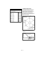
1
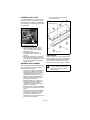
Triplex Reel Mower
Owner/Operator Manual
Model
99500500 – 8400
ENGLISH
ENGLISH
03296500 4/08
Printed in USA
TABLE OF CONTENTS
SAFETY . . . . . . . . . . . . . . . . . . . . . . . . . 3
STORAGE . . . . . . . . . . . . . . . . . . . . . . 26
OPERATION . . . . . . . . . . . . . . . . . . . . . . 8
TROUBLESHOOTING . . . . . . . . . . . . . 27
ASSEMBLY. . . . . . . . . . . . . . . . . . . . . . 13
SPECIFICATIONS . . . . . . . . . . . . . . . . 28
SERVICE AND ADJUSTMENTS . . . . . 16
WARRANTY . . . . . . . . . . . . . . . . . . . . . 29
MAINTENANCE . . . . . . . . . . . . . . . . . . 21
INTRODUCTION
NON-ENGLISH MANUALS
THE MANUAL
Manuals in languages other
than English may be obtained
from your Dealer. Visit your
dealer or www.ariens.com for a
list of languages available for
your equipment.
Manuals printed in languages
other than English are also
available as a free download
on our website:
http://www.ariens.com
MANUALES EN IDIOMAS
DIFERENTES DEL INGLES
Puede obtener manuales en
idiomas diferentes del inglés
en su distribuidor. Visite a su
distribuidor o vaya a
www.ariens.com para obtener
una lista de idiomas
disponibles para su equipo.
También puede imprimir
manuales en idiomas
diferentes del inglés
descargándolos gratuitamente
de nuestra página Web:
http://www.ariens.com
MANUELS NON ANGLAIS
Des manuels dans différentes
langues sont disponibles chez
votre revendeur. Rendez-vous
chez votre revendeur ou allez
sur le site www.ariens.com
pour consulter la liste des
langues disponibles pour votre
équipement.
Les manuels imprimés dans
des langues différentes de
l'anglais sont également
disponibles en téléchargement
gratuit sur notre site Web:
http://www.ariens.com
This manual has been prepared by National
Mower as an aid to users for set up,
operation, and servicing parts. Additional
information will gladly be furnished by calling
or writing the company.
Please furnish us with the Model number,
Serial number, and date of purchase when
contacting us about your machine.
Designations of right, left, front, and rear are
used in the position of the operator sitting in
the seat.
Metric equivalents are provided wherever
possible for users outside of the United
States.
Carefully inspect your machine and crates for
damage that could have occurred during
shipment. If damages or shortages are noted,
have the transportation company’s
representative note this on the bill of lading.
IMPORTANT: Claims for shipping damages
must be noted by the consignee at the point
of designation and filed with the
transportation company.
SERVICE AND REPLACEMENT
PARTS
When ordering replacement parts or making
service inquiries, know the Model and Serial
numbers of your unit and engine.
Numbers are located on the product
registration form in the unit literature
package. They are also printed on a serial
number label, located on the frame of your
unit.
GB - 2
© Copyright 2008 Ariens Company
PRODUCT REGISTRATION
DEALER DELIVERY
The National Mower dealer must register the
product at the time of purchase. Registering
the product will help the company process
warranty claims or contact you with the latest
service information. All claims meeting
requirements during the limited warranty
period will be honored, whether or not the
product registration card is returned. Keep a
proof of purchase if you do not register your
unit.
Customer Note: If the Dealer does not
register your product, please fill out, sign and
return the product registration card to
National Mower or go to
www.nationalmower.com on the internet.
Dealer should:
1. Check that all assembly and
adjustments have been properly
completed.
2. Fill out Original Purchaser Registration
Card and return the card to National
Mower.
3. Explain Turf Products Limited Warranty
Policy.
4. Explain recommended lubrication and
maintenance. Advise customer on
adjustments.
5. Instruct customer on controls and
operation of unit. Discuss and
emphasize the Safety Rules. Advise
customer to thoroughly read and
understand all operating manuals
supplied with the unit.
UNAUTHORIZED REPLACEMENT
PARTS
Use only National Mower replacement parts.
Replacing any part on this vehicle with
anything other than a National Mower
authorized replacement part may adversely
affect the performance, durability, or safety of
this unit and may void the warranty. National
Mower disclaims liability for any claims or
damages, whether warranty, property
damage, personal injury or death arising out
of the use of unauthorized replacement parts.
To locate your nearest National Mower
Dealer, go to www.nationalmower.com on the
internet.
DISCLAIMER
reserves the right to discontinue, make
changes to, and add improvements upon its
products at any time without public notice or
obligation.The descriptions and specifications
contained in this manual were in effect at
printing. Equipment described within this
manual may be optional. Some illustrations
may not apply to your unit.
SAFETY
WARNING: This cutting machine is
capable of amputating hands and
feet and throwing objects. Failure to
observe the safety instructions in
the manuals and on decals could
result in serious injury or death.
Slopes are a major factor related to
loss-of-control and tip-over
accidents. Operation on all slopes
requires extra caution.Tragic
accidents can occur if the operator
is not alert to the presence of
children. Never assume that
children will remain where you last
saw them. Gasoline is extremely
flammable and the vapors are
explosive, handle with care.
Disengage attachment, stop unit
and engine, remove key, engage
parking brake, and allow moving
parts to stop before leaving
operator’s position.
SAFETY ALERT
SYMBOL
OL1253
These are safety alert
symbols. They mean:
•ATTENTION!
•YOUR SAFETY IS
INVOLVED!
When you see this
symbol:
•BECOME ALERT!
•OBEY THE MESSAGE!
OL3900
SIGNAL WORDS
The safety alert symbols above and signal
words below are used on decals and in this
manual.
Read and understand all safety messages.
GB - 3
SAFETY DECALS
DANGER: IMMINENTLY
HAZARDOUS SITUATION! If not
avoided, WILL RESULT in death or
serious injury.
National Mower has provided decals in many
locations throughout the machine to aid the
operator in identifying, controlling and
operating the 8400 safely and correctly. It is
important that all decals are clean and visible
at all times. Replace decals that are
damaged, missing or accidently painted over.
WARNING: POTENTIALLY
HAZARDOUS SITUATION! If not
avoided, COULD RESULT in death
or serious injury.
1. DANGER! KEEP HANDS AND FEET
AWAY
CAUTION: POTENTIALLY
HAZARDOUS SITUATION! If not
avoided, MAY RESULT in minor or
moderate injury. It may also be used
to alert against unsafe practices.
NOTATIONS
NOTE: General reference information for
proper operation and maintenance practices.
NOTE: Specific procedures or information
required to prevent damage to unit or
attachment.
PRACTICES AND LAWS
Practice usual and customary safe working
precautions, for the benefit of yourself and
others. Understand and follow all safety
messages. Be alert to unsafe conditions and
the possibility of minor, moderate, or serious
injury or death. Learn applicable rules and
laws in your area, including those that may
restrict the age of the operator.
1
2. CAUTION!
REQUIRED OPERATOR
TRAINING
Original purchaser of this unit was instructed
by the seller on safe and proper operation. If
unit is to be used by someone other than
original purchaser (loaned, rented or sold),
ALWAYS provide this manual and any
needed safety training before operation.
Emission Control System
Certification Label
NOTE: Tampering with emission control and
components by unauthorized personnel may
result in severe fines or penalties. Emission
controls and components can only be
adjusted by EPA and/or CARB authorized
service centers. Contact your National Mower
retailer concerning emission controls and
component questions.
GB - 4
Read
Owner/Operator
Manual before
servicing machine.
Reduce ground speed when
operating unit down hill.
Keep people away from unit
while operating.
2
SAFETY RULES
Read, understand, and follow all safety
practices in Owner/Operator Manual before
beginning assembly. Failure to follow
instructions could result in personal injury
and/or damage to unit.
Complete a walk around inspection of unit
and work area to understand:
• Work area • Your unit • All safety decals
Determine which attachments are needed
and can be used safely.
Inspect unit before each use for: missing or
damaged decals and shields, correctly
operating safety interlock system, and
deterioration of grass catchers. Replace or
repair as needed.
ALWAYS check overhead and side
clearances carefully before operation.
ALWAYS be aware of traffic when operating
along streets or curbs.
Keep children and people away.
Keep children out of work area and under
watchful care of a responsible adult.
Keep area of operation clear of all toys, pets,
and debris. Thrown objects can cause injury.
Check for weak spots on docks, ramps or
floors. Avoid uneven work areas and rough
terrain. Stay alert for hidden hazards or traffic.
DO NOT operate near drop-offs, ditches, or
embankments. Unit can suddenly turn over if
a wheel is over the edge of a cliff or ditch, or if
an edge caves in.
Data indicates that operators, age 60 and
above, are involved in a larger percentage of
riding mower related injuries. These
operators should evaluate their ability to
operate the riding mower safely enough to
protect themselves and others from serious
injury.
Read the entire Owner/Operator manual and
other training material. If the operator or the
mechanic cannot read the manual, it is the
owner’s responsibility to explain it to them.
Only the user can prevent and is responsible
for accidents or injuries occurring to
themselves, other people or property.
Only trained adults may operate or service
unit. Training includes actual operation.
Local regulations may restrict the age of the
operator.
NEVER allow children to operate or play on
or near unit. Be alert and shut off unit if
children enter area.
NEVER operate unit after or during the use of
medication, drugs or alcohol. Safe operation
requires your complete and unimpaired
attention at all times.
DO NOT wear loose clothing or jewelry and
tie back hair that may get caught in rotating
parts.
Wear adequate outer garments.
NEVER wear open sandals or canvas shoes
during operation. Wear adequate safety gear,
protective gloves and footwear.
Wear proper footwear to improve footing on
slippery surfaces.
GB - 5
Always wear safety goggles or safety glasses
with side shields when operating mower.
Moving parts can cut or amputate fingers or a
hand. Wrap blade(s) or wear gloves to
service. On multiblade mowers, rotation of
one blade will cause all blades to rotate.
NEVER place your hands or any part of your
body or clothing inside or near any moving
part while unit is running.
ALWAYS keep hands and feet away from all
rotating parts during operation. Rotating parts
can cut off body parts.
ALWAYS keep body and hands away from
pin holes or nozzles which eject hydraulic
fluid under pressure.
DO NOT touch parts which are hot. Allow
parts to cool.
ALWAYS keep hands and feet away from all
pinch points.
Read, understand, and follow all instructions
in the manual and on the machine before
starting.
Understand:
How to operate all controls
The functions of all controls
How to STOP in an Emergency
Braking and steering characteristics
Turning radius and clearances
Keep safety devices or guards in place and
functioning properly. NEVER modify or
remove safety devices.
Do not operate without either entire grass
catcher or the discharge guard in place.
Stop engine before removing grass catcher or
unclogging chute.
Ensure Safety Interlock System is functioning
properly. DO NOT operate unit if safety
interlock is damaged or disabled.
Use care when approaching blind corners,
shrubs, trees or other objects that may
obscure vision.
Dust, smoke, fog, etc. can reduce vision and
cause an accident. Mow only in daylight or
good artificial light.
Avoid slippery surfaces. Always be sure of
your footing.
DO NOT mow on wet grass. Reduced
traction could cause sliding and effect the
machine’s stability.
Watch for traffic when operating near or
crossing roadways.
Never carry passengers.
DO NOT try to stabilize the machine by
putting your foot on the ground.
Never direct discharge towards persons or
property that may be injured or damaged by
thrown objects. Use extreme caution on
gravel surfaces.
Always stand clear of the discharge area.
ALWAYS disengage PTO, stop unit and
engine, remove key, engage parking brake
and allow moving parts to stop before leaving
operator’s position.
Never engage PTO while raising attachment
or when attachment is in raised position.
DO NOT operate at too fast a rate. DO NOT
change engine governor settings or overspeed engine. Slow down before turning.
DO NOT operate in reverse unless absolutely
necessary. ALWAYS look down and behind
before and while backing.
Stop and inspect equipment if you strike an
object or if there is an unusual vibration.
Repair, if necessary, before restarting. Never
make adjustments or repairs with the engine
running.
Mower blades are sharp and can cut you.
Wrap the blade(s) or wear gloves, and use
extra caution when servicing them. NEVER
weld or straighten mower blades.
Rotation of one blade may cause rotation of
the other blades.
Take all possible precautions when leaving
unit unattended. Shut off engine. Remove
wire from spark plug and secure it away from
spark plug.
ALWAYS remove key to prevent unauthorized
use.
Know the weight of loads. Limit loads to those
you can safely control and the unit can safely
handle.
Disengage PTO when attachment is not in
use. ALWAYS turn off power to attachment
when travelling, crossing driveways, etc.
Mow up and down slopes, not across them.
Keep all movements on the slope slow and
gradual. Do not make sudden changes in
speed or direction.
Avoid starting or stopping on the slope. If tires
lose traction, disengage the blades and
proceed slowly straight down the slope.
If you cannot back up a slope or you feel
uneasy on it, do not mow it.
DO NOT park on slopes unless necessary.
When parking on slope always chock or block
wheels. Always set parking brake.
GB - 6
Use a slow speed. Tires may lose traction on
slopes even though the brakes are
functioning properly.
Do not bypass transmission when on a slope.
Tow only with a machine that has a hitch
designed for towing. Do not attach towed
equipment except at the hitch point.
Follow the manufacturer’s recommendations
for weight limits for towed equipment and
towing on slopes.
NEVER allow children or others in or on
towed equipment.
On slopes, the weight of the towed equipment
may cause loss of control.
Travel slowly and allow extra distance to stop.
Use extra care when loading or unloading
unit onto trailer or truck.
Secure unit chassis to transport vehicle.
NEVER secure from rods or linkages that
could be damaged.
DO NOT transport machine while engine is
running.
ALWAYS turn off power to attachment and
shut off fuel when transporting unit.
Keep unit free of debris. Clean up oil or fuel
spills.
ALWAYS block wheels and know all jack
stands are strong and secure and will hold
weight of unit during maintenance.
Release pressure slowly from components
with stored energy.
NEVER attempt to make any adjustments to
unit while engine is running (except where
specifically recommended). Stop engine,
remove key or spark plug wire and wait for all
moving parts to stop before servicing or
cleaning.
Check parking brake operation frequently.
Adjust and service as required.
ALWAYS maintain unit in safe operating
condition.
Maintain or replace safety and instruction
labels, as necessary.
Lower cutting deck unless a positive
mechanical lock is used.
Use only attachments or accessories
designed for your unit.
Check all hardware at regular intervals,
especially blade attachment bolts. Keep all
hardware properly tightened.
Check attachment components frequently. If
worn or damaged, replace with
manufacturer’s recommended parts.
GB - 7
OPERATION
CONTROLS AND FEATURES
Figure 1
Ignition Switch
Hour Meter
Insert key in switch (1, Figure 1) and turn
clockwise as far as it will go to start engine,
then release. The reel control switch must be
in the off position and the traction control
pedal in the neutral position before starting
engine.
Do not hold key in “on” position more than 30
seconds at a time.
Key should be removed when tractor is not in
use to prevent unauthorized operation.
See STARTING THE ENGINE on page 11 for
complete starting information.
The hour meter (2, Figure 1) indicates the
number of hours the tractor has been
operated. It can be used to keep track of
maintenance intervals and the amount of time
required to perform various tasks. The hour
meter operates whenever the ignition key is
in the “on” position.
Amp Meter
The amp meter (3, Figure 1) indicates the
condition of the charging circuit. It should
indicate a positive charge during normal
mowing. If the amp meter indicates a
negative reading, refer to the Briggs and
Stratton engine manual.
GB - 8
Choke
Parking Brake
When starting a cold engine, pull the choke
control (4, Figure 1) out to close the choke
plate and allow a richer fuel mixture to enter
the engine. After the engine starts, push the
choke control about halfway in to keep the
choke pate partially closed. Push the choke
control all the way in to open the choke plate
for normal operation after the engine is
properly warmed. A warm engine usually
requires less choke to start.
A convenient parking brake (9, Figure 1) is
located just below the right side of the
operator’s seat.
Pulling back and over center will engage the
parking brake, and moving it forward, as
shown, will release it.
Throttle Lever
Push throttle lever (5, Figure 1) forward to
increase engine speed; pull back to decrease
the engine speed.
Position throttle at full throttle or slightly less
for optimum power and reel speed during
mowing.
Traction Pedal
The traction pedal (6, Figure 1) operates the
forward and reverse direction and speed of
the tractor.
Moving forward: push the forward or toe of
the pedal down with the ball of your foot to
increase the forward speed.
Moving backward: push the heel of the pedal
down with the heel of your foot to increase
the reverse speed.
When the traction pedal is released, the
machine will slow down and stop. The
traction pedal must be in neutral position
before mower will start.
IMPORTANT: Always make sure brake is
released before moving forward, and ensure
that the brake is engaged when leaving the
mower. Never try to stop the forward motion
of the unit with the parking brake.
Reel Drive Control
By toggling the reel drive control switch ON
(10, Figure 1), an electric clutch is activated
which engages power to the reels.
Pushing the switch to the OFF position
disengages the clutch. This control must be in
the OFF position before mower will start.
Seat Position Lever
The position of the seat is adjusted forward or
backward by actuating the seat lever (11,
Figure 1).
Releasing the lever will lock the seat at its
present position.
Rear Mower Lift Lever
Move the rear mower lift lever (1, Figure 2) up
and forward over center; the rear mower will
be held off the ground.
Pull the lever up and back; the rear mower is
lowered for operation or storage.
Speed Control
The speed control (7, Figure 1) is meant to
ease operator fatigue by holding the forward
speed to a constant that is best suited for the
present mowing conditions.
Adjust the hex head bolt up or down and lock
it with the lock nut to limit the pedal travel.
Swing the speed control away from the
traction pedal to again allow a full range of
forward speeds.
Wing Mower Lift
Positioning the wing mower lift lever (8,
Figure 1) will lower the side mowing units to
the ground.
Pulling lever back and over center holds the
mowers off the ground. Always keep mowers
up when not mowing or transporting. Keep
mower down during storage.
CAUTION: Do not stand on mowers
when in lifted position.
Figure 2
Free-Wheeling Valve
To permit moving the machine without
starting the engine, a free-wheeling device or
tow valve has been provided. The lever (1,
Figure 3) is located between the engine and
hydraulic pump.
GB - 9
To open the valve to permit free-wheeling,
simply lift up on the rod and latch washer face
(2, Figure 3) onto the bracket slot.
Reverse the procedure for normal operation
of the machine.
NOTE: Valve must be closed to operate
machine.
5. Check oil level in hydraulic reservoir. Oil
level should be the level shown on the
decal on the side of the oil tank when
unit is sitting on a level surface.
6. Check reels for desired cutting height.
To provide a satisfactory cut, it is
essential for all reels to be accurately
adjusted to exactly the same height. See
HEIGHT OF CUT ADJUSTMENT on
page 18.
NOTE: If adjustments are necessary, see
SERVICE AND ADJUSTMENTS on page 16
for instructions.
OPERATING SUGGESTIONS
Engine
Figure 3
Interlock Switches
There are three safety switches on your
8400. They are a safety precaution which will
allow you to start your mower only when the
traction pedal is in neutral, the reel control
switch is in the disengaged position, and the
operator is seated on the tractor. If you are
able to start your mower with the pedal or
switch in any other position, adjustment of the
switched is required.
Your machine is powered by a twin cylinder, 4
cycle Briggs and Stratton Vanguard engine
which uses unleaded gasoline, 85 octane
minimum. DO NOT MIX OIL WITH
GASOLINE! Engine speed is controlled by
means of a throttle lever mounted on the
dash panel.
A separate Engine Manual, prepared by the
engine manufacturer, is supplied. Study the
manual carefully until you are familiar with the
maintenance, operation, adjustment and
repair of your equipment. Proper attention to
the engine manufacturer’s directions will
assure maximum service life of the engine
and highest operating efficiency.
Traction Drive Train
Power from the engine is transmitted by belt
to the variable displacement pump. The
pump supplies hydraulic fluid to the hydraulic
motors.
Reel Drive
Power to the reels is transmitted from the
engine to a countershaft shaft, which is
controlled by an electric clutch switched on
and off at the dash.
PRIOR TO STARTING THE UNIT
1. Fill the gas tank with good quality, clean,
regular unleaded gasoline, 85 octane
minimum. DO NOT use hi-test gasoline
or an oil/gasoline mixture. Fill tank to 1
inch (25 mm) below filler neck. Do not
overfill.
2. Check oil in the engine crankcase. It
should be filled to the full mark on the
dipstick. See Lubrication Specifications
in this manual for recommend oil
viscosity.
3. Check all lubrication points outlined in
“LUBRICATION on page 23.”
4. Check tires for proper inflation. See
Mower Specifications in this manual.
GB - 10
CAUTION: Under no circumstances
should the engine be started with
the operator or bystander standing
next to tractor or cutting units.
1. When starting the engine, the operator
must be seated on the seat, reel control
switch must be off, and traction pedal
must be in neutral (the center position).
2. The operator should practice mowing in
an open clear area to become
thoroughly familiar with the operation of
the tractor.
3. Never operate the mowers when they
are not cutting grass, as excessive
friction and heat will develop between
the bedknife and reel, damaging the
cutting edge.
4. Plan your cutting pattern to avoid any
unnecessary stops or sharp, frequent
turns. Study the area to determine the
best mowing procedure. Consider the
height of the grass and the type of
terrain (level, hilly, or rough). Each
condition will require certain adjustments
or precautions.
5. Before leaving the mower, always lower
wing mowers so that when exiting the
mower and stepping on the non-skid
pads of the wing mowers, it will not put
excessive strain on the lift mechanism.
6. Operate at speeds which allow you to
have complete control of the tractor and
allow you to stop the tractor or
maneuver safely in case of an
emergency. It is recommended that you
adjust the Speed Control (7, Figure 1) to
maintain a constant pedal
position/speed and reduce the operator
fatigue.
7. To obtain maximum mower life, the
operator must use discretion when
mowing near gravel areas (roadway,
parking areas, cart paths etc.). By
operating too close to overlapping gravel
areas, stones maybe picked up by the
mower and forced between bedknife
and reel, causing wear and serious
damage to the cutting unit.
8. Push choke control in as engine warms
up (or immediately if engine is warm).
DRIVING THE TRACTOR
1. Position throttle at full throttle or slightly
less for optimum power and reel speed.
2. Release parking brake (9, Figure 1).
3. Moving forward: Push the toe of the
traction pedal forward with the ball of
your foot to increase the forward speed.
4. Moving backward: Push the heel of the
traction pedal in with the heel of your
foot to increase the reverse speed.
5. To return traction pedal to neutral, rock
pedal with foot until pedal stops. The
pedal will stay in neutral when you
remove your foot.
DANGER: To avoid possible loss of
control and/or serious bodily injury,
avoid abrupt changes in the traction
pedal position. Reduce speed on
slopes, rough terrain, and in sharp
turns to prevent tipping or loss of
control.
STARTING THE ENGINE
MOWING OPERATION
Figure 4
1. Open the fuel tank shut off valve (1,
Figure 4) (located by the fuel tank) on
the fuel line by turning knob
counterclockwise.
2. Sit in operator’s seat.
3. Place reel control switch in the “Off”
position.
4. Place the traction pedal in “Neutral”
position.
5. Pull choke control out and move throttle
control lever to mid position.
6. Engage parking brake.
7. Insert ignition key, turn clockwise to
“start” position, and release key when
engine starts. Do not hold key in “start”
position for more than 30 seconds or
damage to the starter may result. If
engine does not start within this time,
release the key and wait for a few
minutes before trying again.
GB - 11
1. Check the turf area for debris that would
cause damage to the reels. Never
operate the mowers when they are not
cutting grass, as excessive friction and
heat will develop between the bedknife
and reel, which will damage the cutting
edge.
2. When cutting large areas, the most
satisfactory method is to first cut the
outer area and then mow clockwise
toward the center. The next time you cut,
it is advised that you mow in the
opposite direction to prevent grass
matting.
3. Cutting speeds are governed by
conditions of turf, type of terrain, and
obstacles to be encountered. Operate
tractor at slow speeds when turning.
MOWING
HILLSIDE OPERATION
1. Stop tractor by releasing the traction
pedal (8, Figure 1), then slowly lower the
mower units.
CAUTION: Dropping cutting units
abruptly could damage them or the
H-frame of the wing mowers.
2. Engage reel control switch (10, Figure 1)
to the "On" position.
3. Depress traction pedal to the desired
speed (see Traction Pedal on page 9
and Speed Control on page 9). Reel
speed is constant and ground speed is
variable with the traction pedal. Do not
try to regulate ground speed with engine
throttle (see Throttle Lever on page 9).
VERTICAL MOWING UNIT
1. Be aware that the blades can extend
below the roller. Use care when lowering
cutting units down onto a hard surface to
avoid bending the blades.
2. Setting the depth of cut: Always start
with shallow, less aggressive cuts. Set
the blades to zero (blade tips even with
bottom of roller). Gradually increase
depth of cut until suitable results are
obtained (see HEIGHT OF CUT
ADJUSTMENT on page 18).
3. Keep in mind that vertical mowing is
similar to cutting grass; you can be too
aggressive. When vertical mowing grass
that has never been vertical mowed,
avoid going too deep to start with.
Gradually increase the depth of cut to
obtain desired results.
CAUTION: Dropping the vertical
cutting units abruptly could damage
the blades and/or the H-frame of the
wing mowers.
The 8400 has been designed for good
traction and stability under normal mowing
conditions. However, caution must still be
used during slope operation, especially when
the grass is wet.
Wet grass limits traction and steering control.
In order to minimize the possibility of tipping,
the least dangerous method of operating on
hills and terraces is to travel horizontally to
the hill. It is also advisable to avoid any
unnecessary turns while operating on hills.
Use extreme caution and travel at reduced
speeds.
1. When operating on hillsides or slopes,
maintain full engine speed, but let up on
the traction pedal as power
requirements increase. This will
maintain the performance necessary.
2. It is best to mow along the side of the
hill, starting at the bottom and working
upwards. This allows the machine to
negotiate the slope without mowing in a
downhill direction.
3. It is essential for the correct tire pressure
to be established for maximum traction
and hillside holding.
PUSHING OR TOWING
INSTRUCTIONS
The 8400 has a free-wheeling valve, or “tow
valve,” which will permit moving the machine
at slow speeds without starting the engine.
Do not exceed 2 mph (3 km/h) while pushing
or towing (see Free-Wheeling Valve on
page 9).
AFTER OPERATION
GB - 12
1. Clean the entire mower after use.
Remove loose grass clippings and
caked grass to prevent clogging the
vented lubrication points and corroding
parts.
2. The engine is air cooled. Do not permit
dirt or grass clippings to accumulate on
the air intake screen, cylinder heads, or
on hydraulic pump cooling fan to prevent
serious heat damage to the engine or
hydraulic pump.
3. If fan blades become damaged, replace
the fan.
ASSEMBLY
TRACTOR
Check Tire Pressure
CAUTION: Avoid injury! Explosive
separation of tire and rim parts is
possible when they are serviced
incorrectly:
• Do not attempt to mount a
tire without the proper
equipment and experience to
perform the job.
• Do not inflate the tires above
the recommended pressure.
• Do not weld or heat a wheel
and tire assembly. Heat can
cause an increase in air
pressure resulting in an
explosion. Welding can
structurally weaken or
deform the wheel.
• Do not stand in front or over
the tire assembly when
inflating. Use a clip-on chuck
and extension hose long
enough to allow you to stand
to one side.
CAUTION: Handle banding
material with caution. Use heavy
leather gloves. Banding is sharp!
1. Remove crating top, front, and sides.
2. Cut banding from around tractor, tires,
and armrest box.
3. Separate steering wheel from tire.
4. Remove rear mower belt shield from
manual lift handle.
CAUTION: Use jack stands under
tractor whenever elevated off the
tires.
Lift tractor up off axle crate supports to
sufficiently assemble tire and wheels to the
tractor.
Lower tractor down onto crate. Tractor may
now be driven or rolled off the crate. To allow
the tractor to roll freely without engaging the
engine or drive, a tow valve is provided. It is
located under the hood directly behind the
engine (see Figure 3).
SEAT
REAR MOWER
1. Remove rear mower from crate and
position behind tractor as shown in
Figure 5.
2. Pivot rear mower lifter handle (1,
Figure 5) up and back to lower rear
mower pull plate on the pull yoke.
Position mounting flange (2, Figure 6)
on the center front of the rear mower
frame under the pull plate (3, Figure 6)
and fasten securely with two fasteners
already installed in pull plate.
3. Install V-belt (4, Figure 5) onto double
groove pulley (5, Figure 5) located on
the right rear side of the frame. Raise
rear mower belt idler (6, Figure 5), and
run V-belt under idler pulley as shown.
4. Position rear mower clutch guard (7,
Figure 5) over rear mower shaft and
pulley area, and fasten right side to
support (8, Figure 5) with a 1/4”–20 x
1/2” round-head slotted screw. Secure
rear flange of guard with (2) 1/4”–-20 x
1/2” hex head cap screws, lock washers,
and nuts.
GB - 13
1. Fasten seat /slide assembly studs (1,
Figure 7) into slotted holes in hinge
mounting plate (2, Figure 7) four places
and fasten with four 5/16” flat washers
and nuts.
2. Remove armrests (3, Figure 8) from box
strap to the crate. Attach to seat with
fasteners provided.
Figure 5
Figure 8
STEERING WHEEL
1. Remove nut and washer (1, Figure 9)
from steering shaft (2, Figure 9).
2. Remove steering wheel cap (3,
Figure 9) from steering wheel (4,
Figure 9).
3. Assemble steering wheel onto shaft,
positioning the steering wheel cross
bars parallel when the front tires are in
the straight-ahead position and secure
with the nut and washer. Replace
steering wheel cap.
Figure 6
Figure 9
Figure 7
Figure 10
GB - 14
WING MOWERS
4. Remove the cap screw (4, Figure 12)
closest to the inside of the tractor
fastening the shield to the cross bar.
5. Attach chain bracket (5, Figure 12),
positioning the bracket with the longest
leg to the outside of the cutting unit.
6. Fasten the shorter length of chain to the
chain bracket by using similar fasteners
and method described above.
7. Repeat lift chain installation procedure
on the other side of the mower.
8. Test wing mower lift operation by pulling
lift lever all the way back (toward the
rear). Wing mowers should raise 2” to 3”
above ground level. Adjust, if necessary,
by fastening through another link in the
chain at the upper end of the lift
assembly.
1. Remove wing mowers from crate.
Position on each side of tractor with the
yoke pins (1, Figure 10) facing the
tractor.
2. Remove the two wing mower belts (2,
Figure 11) fastened to the rear cutting
unit and install over lower countershaft
pulleys (3, Figure 11) on each side of the
tractor. Place belt loosely over the end of
the wing mower pull yoke (4, Figure 10).
3. Move left and right cutting units into
position so that the yoke pins enter the
pivot holes in the pull yoke.
NOTE: Forward yoke pins must pass inside
belt before attaching pins to pull yokes.
4. Secure yoke pins in pull yoke with 3/4”
I.D. flat washers and 1/4” x 1–1/2” cotter
pins (5, Figure 10). Extra washers
supplied are to be used as spacers, if
needed, to allow a snug but free-moving
pivot connection.
5. Pull cutting units forward so that the H
Frames (6, Figure 10) will compress the
springs (7, Figure 10), and install belts
over reel pulleys (8, Figure 10).
6. Compress belts by hand to check for
free movement of the H-frames back
and forth on the H-frame shafts (9,
Figure 10).
Figure 12
ENGINE CRANKCASE
Crankcase oil has been installed at the
factory. However, it is recommended that the
engine be checked for proper oil level before
starting. Refer to separate engine manual
included with each 8400 Mower.
Figure 11
WING MOWER LIFT
1. Position lift chain (1, Figure 12) that has
been previously attached to lift lever (2,
Figure 12) so that the longest chain
extends away from the tractor.
2. Attach it to attachment tab (3, Figure 12)
located on the middle of the front edge
of the wing mower using a 3/8”-24 x 13/4” bolt, two 3/8” flat washers, and two
3/8”-24 lock nuts.
3. Place bolt through the ends of the chain
so that lock nuts on each side of
attachment tab allow chain to move
freely between the flat washers.
HYDRAULIC OIL
GB - 15
1. The hydraulic oil has been installed in
the oil tank (1, Figure 13) at the factory,
however, it is recommended that the oil
level be checked before operation.
2. Check oil level by removing pipe plug (2,
Figure 13). The oil level should be at the
bottom edge of the hole, as indicated by
decal (3, Figure 13). If it becomes
necessary to add a small amount of oil
to the tank, it is added in the pipe plug
hole, possibly using a flexible spout
funnel.
Recommended oil is Chevron Rykon 100 or
Exxon Univus N100, or equivalent hydraulic
oil.
The 8400 is not shipped with a battery. A
group size 70, 12-volt side post battery is
recommended such as Exide model 70-LT60, which is approximately 7-3/16” high, 63/4” wide and 8-5/8” long.
Figure 14
1. Place battery in battery holder (1,
Figure 14) with terminals facing the left
wheel. Insert the hook end of the battery
support rods (2, Figure 14) into holes on
the back vertical surface of the battery
holder.
2. Place battery hold down (3, Figure 14)
over support rods and upper corner of
battery and secure with flat washers and
hex nuts.
3. Attach the ground wire (4, Figure 14) to
the frame as shown. Connect the
ignition wire (5, Figure 14) to the positive
(+) terminal of the battery.
4. Attach the ground wire last to the
negative (–) terminal of the battery.
Figure 13
BATTERY
DANGER: Read and follow the
battery manufacturer’s instructions
on safety, maintenance and
installation procedures.
SERVICE AND ADJUSTMENTS
Read each instruction completely, and make
sure you understand it before making any
adjustments. Follow all the safety
precautions.
DANGER: To avoid possible
serious injury, before making any
adjustments or performing
maintenance, engage parking
brake, place all tractor controls in
neutral, lower cutting units to the
ground, turn ignition switch “off” and
remove key.
2. To adjust the creep of the drive wheels,
loosen the fastener attaching the ball
bearing (3, Figure 15) to the control arm
(4, Figure 15), and move and secure the
bearing within the slot to achieve
TRACTION PEDAL
ADJUSTMENTS
The traction pedal (1, Figure 15) is equipped
with a safety switch (2, Figure 15) and a
neutral centering device. The switch prevents
the engine from starting when the pedal is
positioned in reverse or forward. The
centering device locates neutral positioning of
the pump.
1. Prior to adjusting for creep, elevate the
wheels off the ground and support the
vehicle with jack stands. Any
adjustments should be done while the
hydraulic oil is warm.
neutral.
GB - 16
3. Once the traction pedal has been
adjusted, the safety switch (2, Figure 15)
may have to be re-adjusted by moving
the switch in the range of the slot
provided in the switch bracket. Adjust
the switch so that the engine cannot be
started unless the pedal is in the neutral
position.
Adjusting the hex head bolt (7, Figure 1) up
or down and locking it with the lock nut will
limit the pedal travel. Swing the speed control
away from the traction pedal to allow a full
range of forward speeds.
WING MOWER BELT TENSION
Proper belt tension allows mowers to be
driven without slippage but with belt loose
enough to be deflected slightly at a point
midway between pulleys. An overly tight belt
will cause excessive belt wear. Never allow
oil or grease to get on belt, which would
cause slipping.
1. The wing mowers must slide freely on
pull rods to allow the pull yoke springs to
properly tension the belt. If slippage
occurs, it could be due to a weakened
spring, a stretched belt, or sticky pull
rods.
2. Clean and oil pull rods frequently and
check to see that H-frames are sliding
freely on shafts.
Figure 15
LOWER COUNTERSHAFT CHAIN
ADJUSTMENTT
UPPER COUNTERSHAFT BELT
ADJUSTMENT
The upper countershaft belt is driven by the
electric clutch located on the engine stub
shaft.
Belt adjustment is taken up automatically by
the torsion spring assisted idler arm; no
adjustment is necessary. If belt slippage does
occur, check the idler arm for free movement.
If slippage still occurs, replace belt.
PARKING BRAKE ADJUSTMENT
The parking brake should be set so that it
holds the tractor securely. The parking brake
must be released before the traction pedal is
engaged.
1. Adjust the brake by loosening set screw
in the brake knob and turning knob
clockwise to tighten, or counterclockwise
to loosen, then retighten set screw.
2. After making any adjustments, check
brake on flat ground so that the tractor
will not move with brake engaged.
3. Test further by putting tractor on a hill,
leave the engine on, and engage park
brake. Then test with the engine off.
Chain adjustment is taken up automatically
by the torsion spring-assisted idler arm; no
adjustment is necessary. Periodically check
to see that the idler arm is free to pivot.
REAR MOWER LIFT
The rear mower lift height has been preset at
the factory and normally will not need to be
adjusted.
REAR MOWER DRIVE BELT
TENSION
Rear mower belt adjustment is provided by a
spring tensioned belt idler pulley (1,
Figure 16). The idler pulley must be pressing
down on the lower portion of the rear mower
belt (2, Figure 16).
If further adjustment is necessary due to belt
stretching, relocate the spacers (3, Figure 16)
on the pull rod pivot from position 3 to
position 4 (4, Figure 16), between the pull rod
pivot and the rear mower pull plate.
If proper tension cannot be accomplished by
the above procedure, replace the belt.
GROUND SPEED CONTROL
The speed control (see Speed Control on
page 9) is meant to ease operator fatigue by
holding the forward speed constant.
GB - 17
Figure 16
HEIGHT OF CUT ADJUSTMENT
To set the height of cut, lift the Socket/Vinyl
Cap of the Dial-A-HeightTM (1, Figure 17) up
then turn clockwise (viewed from above) to
lower the roller (4, Figure 17) (raise the height
of cut), or counter-clockwise to raise the roller
(lower the height of cut).
NOTE: Each quarter turn (90°) of the
Socket/Vinyl Cap will raise or lower the height
of cut by approx. 1/32”. A full turn (360°) will
raise or lower the height of cut by approx.
1/8”.
IMPORTANT: Rollers must be adjusted to the
same height so that there will be uniform
cutting the entire width of the mower.
The Height Adjustment Scale Decal (2,
Figure 17) will provide approximate height of
cut corresponding to the Socket/Vinyl Cap
rotation.
1. Sight along the bottom edge of the
Adjuster Tube (3, Figure 17) to achieve
the desired cut height.
2. When making large adjustments to the
height of cut (over 1/2”), it is easier to
make small incremental adjustments to
each side until the desired change is
achieved, making sure the Socket/Vinyl
Cap is locked in position.
3. If very accurate cutting heights are
required, place a board or other gage
plate (of desired thickness) on a smooth
flat surface under each bedknife back
bar (1, Figure 22) and adjust the roller
height accordingly.
Figure 17
REEL TO BEDKNIFE
ADJUSTMENT
DANGER: Use heavy gloves and
be careful. Bedknife and reel blades
are very sharp.
The reel is adjusted to a fixed position
bedknife. This makes a more rugged and
durable frame and retains proper adjustment
longer. The reel adjuster bolt (5, Figure 17)
regulates the reel distance from the bedknife.
1. To reduce the distance, turn the locking
hex nut on each side of the reel down
with special reel adjustment wrench (6,
Figure 17) and then tighten top nut.
2. Proceed slowly and do not over adjust—
about 1/6 (one flat) of a turn on each
side to begin with. Do not get the reel so
tight that it is hard to turn by hand. A too
tight reel will wear much faster. The reel
should “wipe” or lightly touch the
bedknife.
3. Check to see that blades are cutting the
paper all the way across, using paper
strips held between reel and bedknife.
4. Make sure adjustment nuts are tight
before mowing.
REEL END PLAY ADJUSTMENT
As the reel is used, normal wear of the reel
bearings will cause end play. This condition
could cause uneven wear to moving parts
and uneven cutting of turf.
GB - 18
Test for end play periodically by trying to
move the reel from side to side in the frame. If
there is any movement, end play is present.
1. Loosen the lock nut on the adjustment
screw (7, Figure 17) and (Figure 18),
(inside right end of the reel) and turn
adjustment bolt in 1/2 turn or less. Do
not over tighten as excessive bearing
wear can occur.
2. Test again for endplay. If reel is rotating
freely and endplay can not be detected,
retighten the locking nut on adjustment
bolt.
Locknut
and
Screw
Figure 18
VERTICAL MOWING UNIT BLADE CHANGING
1. To change the blades, remove the
vertical mowing unit from the frame.
Unbolt the (2) hangers (see Parts
Manual) from the frame.
2. Remove bearing from the hangers.
Remove by loosening the bearing collet
setscrews.
NOTE: It is also advised to check the
bearings for wear and replace if necessary.
3. Remove nut from the shaft and slide the
blade and spacer off.
4. Reassemble with new blades. Make
sure you time the blades so they are on
a spiral and so that the blades are
pointed in the proper direction. Check to
make sure there is no side play with the
blades when tightening the nut.
5. Re-attach the vertical mowing unit to the
frame.
DANGER: Be extremely careful not
to let tools, your fingers, or clothing
get caught in the reels. Use
approved safety glasses to protect
eyes from flying particles and
abrasives.
1. Make sure to adjust the reel to the
bedknife so that the reel is parallel with
the bedknife and light contact is
maintained.
2. Reels must be run in reverse direction to
be lapped. Remove drive belts and
attach a backlapping machine to the
reel. Follow the instructions furnished by
the backlapping machine manufacturer.
3. With reel running, apply the lapping
compound using a 2” or 3” wide brush.
Apply the compound evenly to the
mowing blades.
4. Stop the reel and examine both bedknife
and reel blades to see that the cutting
edges are uniformly sharp. If not,
gradually tighten nut adjuster (see REEL
TO BEDKNIFE ADJUSTMENT on
page 18), and repeat step 3 above until
the proper sharpness results.
5. Rinse off the compound thoroughly with
water to remove all abrasives. Check for
sharpness and readjust the bedknife if
necessary.
6. Check reel adjustment on each mower
and adjust if necessary so that they will
cut paper cleanly across the full length of
the bedknife when paper is held 90° to
the bedknife and pinched when held
horizontally.
Many types of compounds are available for
lapping. However, we recommend a good
pre-mixed water-soluble compound.
Premixed compound saves the time required
to mix, eliminates the waste, and is available
in all grit ranges from coarse to extra fine.
Contact your local Dealer for types and
ordering information.
BACKLAPPING PROCEDURE
Backlapping is a very important step in
maintaining sharp reel blades on the rear and
wing mowers.
This procedure should be performed when
the reel blades and bedknife become slightly
rounded and the grass cannot be cut cleanly
after adjusting the reel to bedknife clearance
(see REEL TO BEDKNIFE ADJUSTMENT on
page 18).
GB - 19
LAPPING COMPOUND
See your authorized Dealer to order these
lapping compounds.
Lapping Compound
80 Grit – 1-lb.
80 Grit – 11-lb.
80 Grit – 25-lb.
100 Grit – 10-lb.
120 Grit – 11-lb.
120 Grit – 25-lb.
180 Grit – 11-lb.
180 Grit – 1-lb.
180 Grit – 25-lb.
220 Grit – 1lb.
220 Grit – 25-lb.
02841500
59501400
59501700
02071600
59501500
59501800
59501600
02841600
59501900
02841800
59502000
GRINDING PROCEDURE
Reel must be ground at 25° in the direction
shown (Figure 19). Back grind until reel
blades are free from roundness, dents, and
nicks. Spin grind to remove all burrs. All
blades must be on the same diameter.
After grinding the bedknife and reels, backlap
to establish a perfect match between the
bedknife and reel blades.
Back grind in
the direction of
the arrow at 25°
25°
Figure 19
Note centerline
position of reel
to blades.
For maximum cutting efficiency, grind
bedknife top and front edges at 5° (see
Figure 20).
Grind bedknife at
angles shown.
5°
5°
Figure 20
GB - 20
MAINTENANCE
DANGER: To avoid possible
serious bodily injury, before
performing any adjustments,
maintenance, or lubrication, place
all controls in “neutral,” lower the
mowers to the ground, engage
parking brake, turn ignition switch
off, and remove key.
DANGER: Always wear protective
glasses or goggles and protective
clothing when working with
batteries. Always connect the
“ground” (black) cable last and
remove it first whenever performing
any maintenance. Batteries contain
sulfuric acid and generate explosive
mixtures of hydrogen and oxygen
gases. Keep any device which may
cause sparks or flames away from
the battery to prevent explosions.
Read and follow the battery
manufacturer’s instructions on
safety, maintenance, and installation
procedures.
GENERAL MAINTENANCE
The long trouble-free life of your machine
depends on the maintenance it receives. Set
up a maintenance program for your 8400 to
cover the following points:
• Keep tractor and mowers clean.
• Keep all moving parts properly
lubricated (see LUBRICATION on
page 23).
• Keep all parts properly adjusted.
• Inspect for loose, worn or damaged
parts.
• Keep shields in place at all times.
• Keep tires properly inflated.
If your inspection reveals worn or damaged
parts, replace these parts before operating
machine or before actual breakdown occurs.
3. When the battery is being installed or
removed, make sure that the positive
and negative terminals do not come in
contact with metal tractor parts at the
same time, or severe damage may
result.
4. Battery connections must be kept clean
and tight at all times. Loose cables will
cause eventual battery failure. Keep
terminal covers in place.
5. Use soap and water to clean the battery
as required. Care must be taken to
prevent soap and water from getting
inside battery.
6. Clean the terminal contact surfaces with
a battery terminal brush or steel wool.
7. Tighten cables securely to battery
terminals.
8. Apply a light coat of petroleum jelly or
chassis lubricant to terminals and cable
ends after assembly to prevent
corrosion.
DANGER: To avoid injury from hot,
high-pressure oil, never disconnect
hydraulic hoses with attachments in
up position. Never rub hands across
tubes, hoses, or fittings to check for
leaks. Hydraulic fluid escaping
under pressure can have sufficient
force to penetrate the skin.
ASSEMBLY AND DISASSEMBLY
Use the illustrations in the Parts Manual as
reference for disassembly and assembly of
components. Always maintain relative
position of parts when disassembling. Clean
and lubricate individual parts and
components as required.
CHARGING A BATTERY
DANGER: To avoid possible injury,
stand away from battery when
charger is turned on. A damaged
battery or a battery with an internal
short could explode.
BATTERY
1. Make certain the ignition switch is in the
“off” position and the keys have been
removed.
2. Refer to the Mower Specifications in this
manual for battery specifications.
3. Connect charger leads to battery.
Connect the positive (+) connector from
the charger to the positive battery
terminal. Connect the negative (–)
connector of the charger to the negative
Charge battery only in a well-vented location,
away from sparks or open flame.
1. Remove the battery from the tractor
before charging.
2. Be sure charger is “off.“
battery terminal.
4. Charge the battery using one of the
methods shown below. Follow the
manufacturer’s instructions on the
charger.
GB - 21
Slow charge:
• 10 hours @ 5 amps
• 3 hours @ 10 amps
Fast charge:
• 2-1/2 hours @ 20 amps
• 1-1/2 hours @ 30 amps
• 1 hour @ 45 amps
5. If when charging the battery, violent
gassing or spewing of electrolyte occurs,
or the battery case feels hot (125°F 52C), reduce or temporarily halt
charging to avoid damaging battery.
6. Always turn charger to “off” before
removing a charger lead from the
battery.
JUMPER CABLES
The battery on the 8400 is located at the rear
of the tractor (see Figure 14).
1. Stop the engine on the vehicle with the
good battery.
2. Connect one jumper cable to the
positive terminal on the good battery.
Connect the other end of the jumper
cable to either the positive terminal on
the dead battery or the battery side of
the solenoid located on the right front of
the engine.
3. Connect one jumper cable to negative
terminal on dead battery. Connect the
other end to ground (frame) of vehicle
with the good battery.
BELTS
For efficient performance of your machine,
worn or frayed belts must be replaced. Check
belt tensions as instructed (see SERVICE
AND ADJUSTMENTS on page 16).
ENGINE FUEL FILTER
Before servicing the fuel filter, thoroughly
clean outside of filter housing and fuel hoses.
Dirt must not be allowed to enter into fuel or
fuel system. Refer to manufacturer’s Engine
Manual for instructions.
2. Keep wire harness and all individual
wires away from moving parts, hot parts,
or sharp edges. This will prevent
abrasive wear or potential short circuits.
3. Exercise extreme care when working
with electrical system.
HYDRAULIC HOSES
DANGER: To avoid serious bodily
injury, always lower mowers to the
ground, place all controls in neutral
and shut off engine before
inspecting hydraulic lines or hoses.
Never run hands across tubes,
hoses or fittings to check for leaks.
Hydraulic hose and tube lines should be
inspected every week to check for cuts, loose
connections, kinks, and wear.
Be sure tubes and hoses do not come in
contact with other frame parts which could
cause abrasive wear. Always replace worn
hoses or tubes before operating machine.
1. Assemble nut, sleeves and tube to fitting
body with minimum torque (finger tight)
until flare contacts seat on fitting body.
2. For tightening reference, mark a line
lengthwise on both the nut and adapter
fitting with a marker.
3. Using a wrench, rotate the nut to tighten.
Turn the nut to the amount shown in the
chart below. The line will show which
fitting has been tightened and how
much.
4. On hoses with “o-ring” fittings, make
sure o-rings are clean and hose fittings
are properly seated by hand before
wrench tightening.
5. Hold the fixed portion of the hose
coupling with one wrench; use a second
wrench to tighten or loosen the hose nut.
This will prevent damage to the fitting
seal. When tightening a hose, do not
allow it to twist; hold it in a normal,
straight position.
ENGINE
Refer to manufacturer’s Engine Manual for
maintenance schedule recommendations.
Change oil and oil filter after the first 5 to 8
hours of operation.
ELECTRICAL SYSTEM
Make certain all terminals and connections
are kept clean and properly secured.
1. Check switches regularly to be sure they
are kept clean and operating correctly.
GB - 22
Tube O.D. or
Hose
Rotate # of Flats
3/8"
2
1/2"
2
5/8"
1-1/2-2
1"
3/4-1
HYDRAULIC OIL FILTER
5. Torque shoulder nuts 35 to 40 lbf/ft
(47.4 to 54.2 N•m).
To prevent damage to the hydraulic system,
the hydraulic oil filter (1, Figure 21), located
under right fender, should be changed after
the first 25 hours of operation and every 250
hours thereafter.
Clamp this edge
Figure 21
1. Remove the old filter.
2. Install new filter, filling filter with oil
before re-installing. Apply oil to the
o-ring of the filter prior to installation.
Hand-tighten only.
3. Run engine at idle speed with
hydrostatic pump in neutral for five
minutes.
4. Check hydraulic oil level, and add oil if
necessary. Frequently check oil level in
the hydraulic tank. Should the pump run
short of oil, immediate and permanent
damage will result.
Figure 22
LUBRICATION
Figure 23 shows the top view of the 8400 with
guards removed. Lubricate your tractor at the
recommended locations and intervals using
proper lubricants so that maximum service
and long life of the machine may be obtained.
BEDKNIFE REPLACEMENT
When the bedknife becomes damaged or too
worn to keep sharp, it must be replaced.
Follow the procedure below.
1. The backbar (1, Figure 22), bedknife (2,
Figure 22), and fasteners have been
assembled at the factory under tension.
To ease replacement and prevent
misalignment of components, you may
wish to clamp the leading edge of the
backbar two or three places before
removing the old fasteners.
2. Remove shoulder nuts (3, Figure 22)
and flathead screws (4, Figure 22). If
shoulder nuts are badly rusted or
corroded, they may have to be cut off
and the screws driven out.
3. Clean the bottom surface of the backbar
for maximum metal contact with the new
bed bar.
4. Fasten the new bed knife to the bottom
of the backbar in the position shown
(bent edge up). Shoulder of shoulder
nuts must be seated firmly in the
backbar and screws must be flush with
the bottom of the bed knife.
GB - 23
CAUTION: Before doing any work
on your machine, stop the engine,
remove the ignition key, and set
parking brake.
Figure 23
Symbols
GREASE - Lithium base
or Equivalent
OIL - Light machine oil.
GB - 24
Item
Frequency
(Hrs.)
Location
Type of
Lubrication
No. of
Places
1
Daily
Mower Reel Roller Bearing
Grease, Lithium
6
2
Daily
Wing Mower Pull Rod Bushing
Oil
4
3
Daily
Idler Sprocket Chain
Oil
1
4
Daily
Lower Countershaft Bearing
Grease, Lithium
2
5
25
Front Axle Ball Joints
Grease, Lithium
3
6
Daily
Axle Yoke
Grease, Lithium
2
7
25
Neutral Return Pivot
Grease, Lithium
1
8
25
Front Axle Pivot
Grease, Lithium
1
9
25
Upper Countershaft Bearing
Grease, Lithium
2
10
Daily
Pedal Support Bearing
Grease, Lithium
2
11
Daily
Roller Bracket Bushing
Grease, Lithium
6
12
25
Rear Mower Pull Yoke Pivot
Grease, Lithium
1
13
Daily
Rear Mower Countershaft
Grease, Lithium
2
14
25
Rear Mower Lifter Bracket Pivot
Grease, Lithium
1
15
Daily
Countershaft Bearing
Grease, Lithium
2
16
Yearly
Steering Motor
Grease, Lithium
1
GB - 25
STORAGE
GENERAL INSTRUCTIONS
TIRES
When you do not plan to use your vehicle for
some time, it should be stored in a dry and
protected place. Unnecessary exposure to
the elements may deteriorate its appearance
and shorten the usual service life.
1. Before storing the vehicle, clean the tires
thoroughly.
2. Jack up the vehicle so that the load is off
the tires. If it is not jacked up, check the
tires at regular intervals and re-inflate as
necessary to keep them at the
recommended maximum pressure
(Indicated on tire’s side wall).
3. Store the vehicle so that the tires are
protected from sunlight.
ENGINE
1. Drain the fuel from the fuel tank and
carburetor.
2. Operate the engine until the gasoline in
the carburetor is completely consumed.
3. While the engine is still warm, drain the
oil form the crankcase and refill with
fresh oil. Refer to Engine Manual for
manufacturer’s instructions.
4. After engine has cooled, remove the
spark plugs and put about one
tablespoon of SAE 30 oil into the
cylinder.
5. Clean exterior of engine. Paint the
exposed metal or coat it with a light
coating of rust preventative oil.
BATTERY
1. Remove battery and clean it. Refer to
manufacturer’s manual for specific
instructions.
2. Maintenance-free batteries should be
stored in an upright position in a cool dry
place. Storage above 80° F (28 °C)
greatly increases self-discharge. If wet
batteries are discharged, the electrolyte
will freeze when stored below
20° F (-7 °C).
IMPORTANT: The battery should be checked
every 60 to 90 days while in storage and
should be recharged if necessary.
STARTING THE ENGINE AFTER
STORAGE
If mower is cold, move the mower to a heat
location and allow it to come to room
temperature (70°F - 22°C) before starting.
This will prevent premature wear of hydraulic
system components.
Follow the towing procedure (see PUSHING
OR TOWING INSTRUCTIONS on page 12).
1. Check and recharge the battery
according to recommendations (see
CHARGING A BATTERY on page 21).
2. Reinstall the battery
3. Check oil level in crankcase and
hydraulic oil tank.
4. Fill the fuel tank with fresh gasoline.
Check fuel filter. Check fuel shut off
valve; open if necessary.
5. Before driving the vehicle, check to
make certain that the tires are properly
inflated to the proper pressure.
TRACTOR
Wash, clean and completely lubricate the
tractor. Paint any exposed metal.
GB - 26
CAUTION: Avoid injury! Explosive
separation of tire and rim parts is
possible when they are serviced
incorrectly:
• Do not attempt to mount a
tire without the proper
equipment and experience to
perform the job.
• Do not inflate the tires above
the recommended pressure.
• Do not weld or heat a wheel
and tire assembly. Heat can
cause an increase in air
pressure resulting in an
explosion. Welding can
structurally weaken or
deform the wheel.
• Do not stand in front or over
the tire assembly when
inflating. Use a clip-on chuck
and extension hose long
enough to allow you to stand
to one side.
6. Remove the spark plugs and wipe dry.
Crank the engine (with spark plug
removed) using the starter until excess
oil has been expelled through the spark
plug hole. Replace the plug and connect
the ignition lead wires.
7. Move the vehicle outdoors or keep doors
and/or windows wide open to provide
sufficient ventilation before starting
engine. This will prevent danger from
carbon monoxide gas in the exhaust.
8. Start the engine but do not operate at
high speed immediately after starting.
Allow time for it to become properly
warmed and lubricated.
TROUBLESHOOTING
ENGINE WILL NOT START
•
•
•
•
•
•
•
•
•
•
REEL WILL NOT TURN
The operator must be seated.
Check position of reel control switch
(on dash). Switch must be in the OFF
position.
Check to see that the traction pedal is
in neutral (neutral is in the center
position).
Check all safety switches for
conductivity.
Replace switches, if necessary.
Check fuel in tank.
Check if fuel is at the end of fuel line at
carburetor. If not, clean filter or, if
necessary, replace fuel filter.
Check battery. Check charge level;
charge or replace as needed. Clean
battery terminals, if necessary.
Check spark plugs. Check for spark at
spark plugs, check for foul conditions,
or replace spark plugs, if necessary.
Refer to Briggs and Stratton engine
manual for recommended spark plug
and gap.
Check electrical wiring and safety
switch operation. Check wiring or
check traction pedal neutral safety
switch and adjust to allow current flow
from the “S” terminal to the starter
solenoid.
•
•
•
•
•
REEL WILL NOT CUT
TRACTOR WILL NOT MOVE
•
•
•
Check for debris jammed between the
reel and bedknife.
Check for proper belt tension. Belt
tension is not adjustable.
Test wing mower H-frames so that
they are sliding easily. Lubricate, if
necessary.
Check rear mower belt tension idler to
see that idler is moving freely.
Check drive belts between engine
clutch and countershaft pulley to
ensure that spring loaded idler is
moving freely. If slippage still occurs
as a result of belt wear and belt
stretch, replace belt.
Check that parking brake is not
engaged.
Check towing (free-wheeling) valve to
see that it is fully closed (in the down
position).
Check the linkage from the traction
pedal to the pump control mechanism
to ensure complete attachment of all
linkages.
GB - 27
•
•
•
•
Check the reel to bedknife clearance
with common newspaper. The reel
should cut through paper the entire
length of the bedknife.
Inspect reel and bedknife for damage.
Service, if necessary.
If reel is cutting grass too high, too low,
or not at all, the reel height is out of
adjustment. See HEIGHT OF CUT
ADJUSTMENT on page 18.
If reel is cutting grass unevenly from
side to side or not at all, the distance
between the reel and the bedknife is
out of adjustment. See REEL TO
BEDKNIFE ADJUSTMENT on
page 18.
SPECIFICATIONS
Model Number
Engine
Type
Model
Horsepower
Cooling
Transmission
Traction Drive
Wheel Drive Motors
Steering
Eaton Power Steering Control Unit
Mower
Fuel Tank
Oil Tank
Tires
Frame
Mowing Speed
Controls
Battery Type
Cutting Unit
Unit
Reels
Bearings
Bedknife
Width of Cut
Lubricants
Engine Oil
Hydraulic Oil
Vertical Mowing Unit
Cutting Unit
Reels
Bearings
Width of Cut
Height of Cut
995005
Twin Cylinder, Air Cooled
Briggs & Stratton Vanguard
16HP (11.9 kW)
Ducted Airflow
Model 11 Variable
Displacement
Hydrostatic Pump
Eaton Series 2000 Hydraulic Motor
5 Gallons (19 liters)
5 Gallons (19 liters) Approx.
Front: 16x6.50 - 8 (28 psi (1.9 bar) max)
Rear: 23x10.50x12 (20 psi (1.4bar) max)
Welded Steel Construction
0-7 MPH (0-11.3 KM/H)
Foot-operated Traction Pedal for Forward & Reverse
Hand-operated Throttle and Choke Controls
Free-wheeling Tow Valve
Electric Clutch for Cutting Units
Hand-operated Parking Brake
Exide Model 70-LT-60
Group Size 70
12-V Side Post
7-3/16" (18 cm) Height
6-3/4" (17 cm) Width
8-5/8" (22 cm) Length
3-30" (.76 m) Long Reels
8" (20.3 cm) Diameter, 6 or 8 Blade
Timken Tapered Roller
13 x 64 x 2" with Upturned Lip of Alloy Steel
(5.16mm x 50mm)
84" (2.13m)
Refer to Enclosed Engine Manual
Texaco Rando HDZ 100
Chevron Rykon 100 or Exxon Univus N100 or
Equivalent
3-30" (.76m) Long Reels
10" (25.4cm) Diameter, 26 Blades, 1" (2.54cm) Spaced
PEER Bearing Block
84" (2.13m)
-3/8" to 1/2" (-.96 cm to 1.27 cm) Adjustment
GB - 28
Two-Year Limited
Turf Products Warranty
Ariens Company (Ariens) warrants to the original purchaser that all Gravely Turf, Locke Turf or National
Mower brand commercial turf products will be free from defects in material and workmanship for a period of
two years after the date of purchase or 1000 hours of use, whichever comes first. An authorized Gravely Turf,
Locke Turf or National Mower dealer will repair any defect in material or workmanship, and repair or replace
any defective part, subject to the conditions, limitations and exclusions set forth herein. Such repair or
replacement will be free of charge to the original purchaser (labor and parts), except as noted below.
One-Year Limited Warranty on i-Trim Mowers and Pro Vac Lawn Vacuums
Ariens Company (Ariens) warrants to the original purchaser that all Gravely Turf, Locke Turf or
National Mower brand i-Trim mowers or Pro Vac lawn vacuums will be free from defects in material and
workmanship for a period of one year after the date of purchase or 500 hours of use, whichever comes
first. An authorized Gravely Turf, Locke Turf or National Mower dealer will repair any defect in material
or workmanship, and repair or replace any defective part, subject to the conditions, limitations and
exclusions set forth herein. Such repair or replacement will be free of charge to the original purchaser
(labor and parts), except as noted below.
90-Day Limited Warranty on Service Parts and Accessories
Genuine Gravely Turf, Locke Turf or National Mower brand service parts and accessories are warranted to be free from defects in material and workmanship for a period of 90 days after the date of purchase. An authorized Gravely Turf, Locke Turf or National Mower dealer will repair or replace any such
part or accessory free of charge, except for labor, during that period.
If any product is rented or leased, then the duration of these warranties shall be 90 days after the date of
purchase.
Exceptions, Limitations, Exclusions
Customer Responsibilities
Register the product immediately at the time of sale. If the dealer does not register the product, the
customer must complete the product registration card in the literature package and return it to the Ariens
Company, or register the unit online at www.ariens.com, www.gravely.com, or www.nationalmower.com.
To obtain warranty service, the original purchaser must:
• Perform the maintenance and minor adjustments explained in the owner’s manual.
• Promptly notify Ariens or an authorized Gravely Turf, Locke Turf or National Mower service
representative of the need for warranty service.
• Transport the product to and from the place of warranty service.
• Have the warranty service performed by an authorized Gravely Turf, Locke Turf or National Mower
service representative.
To find a Gravely Turf, Locke Turf or National Mower authorized service representative, contact Ariens at:
655 W. Ryan Street
Brillion, WI 54110
(920) 756 - 2141
www.ariens.com
www.gravely.com
www.locketurf.com
www.nationalmower.com
Limitations
•
Batteries are warranted only for a period of 12 months after date of purchase, on a prorated basis. For
the first 90 days of the warranty period, a defective battery will be replaced free of charge. If the
applicable warranty period is more than 90 days, Ariens will cover the prorated cost of any defective
battery, for up to 12 months after the date of purchase.
ARIENS COMPANY
GRAVELY® | STENS® | LOCKE® | NATIONAL® | BYNORM® | EVERRIDE® | GREAT DANE®
Com_Turf_2008
29
Exclusions – Items Not Covered by This Warranty
•
•
•
•
•
•
Engines and engine accessories are covered only by the engine manufacturer’s warranty and are not
covered by this warranty.
Parts that are not genuine Gravely Turf, Locke Turf or National Mower service parts are not covered by
this warranty.
The following maintenance, service and replacement items are not covered by this warranty unless
they are noted in the Limitations section above: lubricants, spark plugs, oil, oil filters, air filters, fuel
filters, brake linings, brake arms, shoes, runners, scraper blades, shear bolts, mower blades, mower
vanes, headlights, light bulbs, knives, cutters.
Mufflers, belts and tires on Gravely Turf, Locke Turf or National Mower turf products are not covered by
this warranty.
Any misuse, alteration, improper assembly, improper adjustment, neglect, or accident which requires
repair is not covered by this warranty.
This warranty applies only to products purchased in the United States (including Puerto Rico) and
Canada. In all other countries, contact place of purchase for warranty information.
Disclaimer
Ariens may from time to time change the design of its products. Nothing contained in this warranty shall be
construed as obligating Ariens to incorporate such design changes into previously manufactured products,
nor shall such changes be construed as an admission that previous designs were defective.
LIMITATION OF REMEDY AND DAMAGES
Ariens Company’s liability under this warranty, and under any implied warranty that may exist, is limited to
repair of any defect in workmanship, and repair or replacement of any defective part. Ariens shall not be
liable for incidental, special, or consequential damages (including lost profits). Some states do not allow the
exclusion of incidental or consequential damages, so the above limitation or exclusion may not apply to you.
DISCLAIMER OF FURTHER WARRANTY
Ariens Company makes no warranty, express or implied, other than what is expressly made in this
warranty. If the law of your state provides that an implied warranty of merchantability, or an implied
warranty of fitness for particular purpose, or any other implied warranty, applies to Ariens Company,
then any such implied warranty is limited to the duration of this warranty. Some states do not allow
limitations on how long an implied warranty lasts, so the above limitation may not apply to you.
This warranty gives you specific legal rights, and you may also have other rights which
vary from state to state.
ARIENS COMPANY
GRAVELY® | STENS® | LOCKE® | NATIONAL® | BYNORM® | EVERRIDE® | GREAT DANE®
Com_Turf_2008
30
National Mower
An Ariens Company
655 West Ryan Street
Brillion, WI 54110-0157
920-756-2141
Fax 920-756-2407
www.nationalmower.com