1
OPERATION AND PARTS MANUAL
SERIES
MODEL HTH44T
RIDE-ON POWER TROWEL
(KUBOTA V1505 DIESEL ENGINE)
Revision #8 (03/27/12)
To find the latest revision of this
publication, visit our website at:
www.multiquip.com
THIS MANUAL MUST ACCOMPANY THE EQUIPMENT AT ALL TIMES.
P/N 20210
PROPOSITION 65 WARNING
Engine exhaust and some of
its constituents, and some dust created
by power sanding, sawing, grinding,
drillingandotherconstructionactivities
contains chemicals known to the State
of California to cause cancer, birth
defects and other reproductive harm.
Some examples of these chemicals are:
Leadfromlead-basedpaints.
Crystallinesilicafrombricks.
Cementandothermasonryproducts.
Arsenicandchromiumfromchemically
treatedlumber.
Your risk from these exposures varies,
depending on how often you do this type
of work. To reduce your exposure to
these chemicals: ALWAYS work in a
well ventilated area, and work with
approved safety equipment, such as
dust masks that are specially designed
to filter out microscopic particles.
PAGE 2 — HTH44T • RIDE-ON POWER TROWEL — OPERATION AND PARTS MANUAL — REV. #8 (03/27/12)
)
SILICOSIS/RESPIRATORY WARNINGS
WARNING
WARNING
SILICOSIS WARNING
RESPIRATORY HAZARDS
Grinding/cutting/drilling of masonry, concrete, metal and
other materials with silica in their composition may give
off dust or mists containing crystalline silica. Silica is a
basic component of sand, quartz, brick clay, granite and
numerous other minerals and rocks. Repeated and/or
substantial inhalation of airborne crystalline silica can
cause serious or fatal respiratory diseases, including
silicosis. In addition, California and some other
authorities have listed respirable crystalline silica as a
substance known to cause cancer. When cutting such
materials, always follow the respiratory precautions
mentioned above.
Grinding/cutting/drilling of masonry, concrete, metal and
other materials can generate dust, mists and fumes
containing chemicals known to cause serious or fatal
injury or illness, such as respiratory disease, cancer,
birth defects or other reproductive harm. If you are
unfamiliar with the risks associated with the particular
process and/or material being cut or the composition of
the tool being used, review the material safety data
sheet and/or consult your employer, the material
manufacturer/supplier, governmental agencies such as
OSHA and NIOSH and other sources on hazardous
materials. California and some other authorities, for
instance, have published lists of substances known to
cause cancer, reproductive toxicity, or other harmful
effects.
Control dust, mist and fumes at the source where
possible. In this regard use good work practices and
follow the recommendations of the manufacturers or
suppliers, OSHA/NIOSH, and occupational and trade
associations. Water should be used for dust
suppression when wet cutting is feasible. When the
hazards from inhalation of dust, mists and fumes cannot
be eliminated, the operator and any bystanders should
always wear a respirator approved by NIOSH/MSHA for
the materials being used.
HTH44T • RIDE-ON POWER TROWEL — OPERATION & PARTS MANUAL — REV. #8 (03/27/12) — PAGE 3
— PAGE RM
HTH44T— TABLE OF CONTENTS
Proposition 65 Warning ............................................ 2
Silicosis/Respiratory Warnings ................................. 3
Table of contents ...................................................... 4
Parts ordering procedures ....................................... 5
Training Checklist ..................................................... 6
Daily Pre-Operation Checklist .................................. 7
Safety Message Alert Symbols ............................ 8-9
Rules For Safe Operation ...................................... 10
Operation And Safety Decals ................................. 11
Specifications ......................................................... 12
General Information ............................................... 13
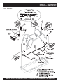
Spray Assy. ........................................................ 82-83
Light Assy. .......................................................... 84-85
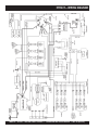
Wiring Diagram ....................................................... 86
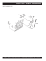
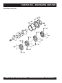
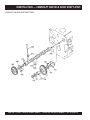
KUBOTA V1505 ENGINE
Crankcase Assembly ......................................... 88-89
Oil Pan Assembly ............................................... 90-91
Cylinder Head Assembly .................................... 92-93
Gear Case Assembly ......................................... 94-95
Dipstick and Guide Assembly ............................ 96-97
Main Bearing Case Assembly ............................ 98-99
Camshaft and Idle Gear Shaft Assembly ....... 100-101
Piston and Crankshaft Assembly ................... 102-103
Flywheel Assembly ........................................ 104-105
Fuel Camshaft and Governor Shaft Assy. ...... 106-107
Engine Stop Lever Assembly ......................... 108-109
Stop Solenoid Assembly ................................. 110-111
Injection Pump Assembly ............................... 112-113
Nozzle Holder Assembly ................................ 114-115
Nozzle Holder Assy(Component Parts) ......... 116-117
Fork Lever (Governor) Assembly ................... 118-119
Fuel Pump (Mechanical) Assembly................ 120-121
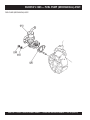
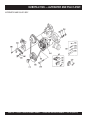
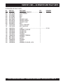
Alternator and Pulley Assembly ..................... 122-123
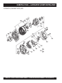
Alternator (Component Parts) Assembly ....... 124-125
Starter Assembly ............................................ 126-127
Starter (Component Parts) Assembly ............ 128-129
Oil Switch/Thermometer & Plug Assy. ........... 130-131
Water flang and Thermostat Assembly .......... 132-133
Water Pump Assembly ................................... 134-135
Water Pipe Assembly ..................................... 136-137
Fan Assembly................................................. 138-139
Valve and Rocker Arm Assembly ................... 140-141
Inlet Manifold Assembly ................................. 142-143
Exhaust Manifold Assembly ........................... 144-145
Turbo-Charger Assembly ............................... 146-147
Oil Pipe Turbo-Charger Assembly.................. 148-149
Hydraulic Pump Assembly ............................. 150-151
Oil Cooler Assembly....................................... 152-153
Glow Plug/Lamp and Timer Assembly ........... 154-155
Engine Stand Assembly ................................. 156-157
Accessories and Service Parts Assy. ............. 158-159
Labels............................................................. 160-161
WHITEMAN — HTH44T RIDEON POWER TROWEL
Controls and Indicators ..................................... 14-15
Initial Start-Up .................................................... 16-19
Maintenance....................................................... 20-25
Troubleshooting .................................................. 26-27
Explanation of Codes In Remarks Column ............ 28
Suggested Spare Parts & Service Items ................29
Pivot Assy. (Left)................................................. 30-31
Pivot Assy. (Right) .............................................. 32-33
Twin Pitch Assy. (Left/Right) .............................. 34-37
Engine (Kubota) ................................................. 38-39
Engine Flange (Kubota) .................................... 40-41
Engine Fuel (Kubota) ......................................... 42-43
Hydraulic Steering (Left) .................................... 44-45
Hydraulic Steering (Right) ................................. 46-47
Steering Valve Assy. (Left) ................................. 48-49
Steering Valve Assy. (Right)............................... 50-51
Palm Handles (Left and Right) .......................... 52-53
Hydraulic Drive Assembly .................................. 54-55
Hydraulic Drive Pump Lever Assy. .................... 56-57
Hydraulic Drive Filters and Cooling................... 58-59
Five Blade Spider Assy. (Left) ........................... 60-61
Five Blade Spider Assy. (Right) ......................... 62-63
Stabilizer Ring Assy. .......................................... 64-65
Locator Decals ................................................... 66-67
Top Panel (Left) .................................................. 68-69
Top Panel (Right) ............................................... 70-71
Front Panel (Right) ............................................. 72-73
Seat and Frame ................................................. 74-75
Frame and Fuel Tank ......................................... 76-77
Foot Pedals ........................................................ 78-79
Battery ................................................................ 80-81
Terms and Conditions of Sale — Parts ................. 162
PAGE 4 — HTH44T • RIDE-ON POWER TROWEL — OPERATION AND PARTS MANUAL — REV. #8 (03/27/12)
)
www.multiquip.com
PARTS ORDERING PROCEDURES
Ordering parts has never been easier!
Choose from three easy options:
Order via Internet (Dealers Only):
Best Deal!
Effective:
January 1st, 2006
If you have an MQ Account, to obtain a Username
and Password, E-mail us at: parts@multiquip.
com.
Order parts on-line using Multiquip’s SmartEquip website!
■ View Parts Diagrams
■ Order Parts
■ Print Specification Information
To obtain an MQ Account, contact your
District Sales Manager for more information.
Use the internet and qualify for a 5% Discount
on Standard orders for all orders which include
complete part numbers.*
Goto www.multiquip.com and click on
Order Parts to log in and save!
Note: Discounts Are Subject To Change
Order via Fax (Dealers Only):
All customers are welcome to order parts via Fax.
Domestic (US) Customers dial:
1-800-6-PARTS-7 (800-672-7877)
Fax your order in and qualify for a 2% Discount
on Standard orders for all orders which include
complete part numbers.*
Note: Discounts Are Subject To Change
Order via Phone: Domestic (US) Dealers Call:
1-800-427-1244
Non-Dealer Customers:
Contact your local Multiquip Dealer for
parts or call 800-427-1244 for help in
locating a dealer near you.
International Customers should contact
their local Multiquip Representatives for
Parts Ordering information.
When ordering parts, please supply:
❒
❒
❒
❒
❒
❒
Dealer Account Number
Dealer Name and Address
Shipping Address (if different than billing address)
Return Fax Number
Applicable Model Number
Quantity, Part Number and Description of Each Part
❒
Specify Preferred Method of Shipment:
✓ UPS/Fed Ex
✓ DHL
■ Priority One
✓ Truck
■ Ground
■ Next Day
■ Second/Third Day
NOTICE
All orders are treated as Standard Orders and will
ship the same day if received prior to 3PM PST.
WE ACCEPT ALL MAJOR CREDIT CARDS!
HTH44T • RIDE-ON POWER TROWEL — OPERATION & PARTS MANUAL — REV. #8 (03/27/12) — PAGE 5
— PAGE RM
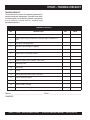
HTH44T— TRAINING CHECKLIST
TRAINING CHECKLIST
This checklist will lists some of the minimum requirements for
machine maintenance and operation. Please feel free to detach
it and make copies. Use this checklist whenever a new operator
is to be trained or it can be used as a review for more
experienced operator’s.
TRAINING CHECKLIST
NO.
DESCRIPTION
1
Read Operator’s Manual completely.
2
Machine layout, location of components, checking of engine and hydraulic oil
levels.
3
Fuel system, refueling procedure
4
Operation of spray and lights (if equipped).
5
Operation of controls (machine not running).
6
Safety controls, seat kill switch operation.
7
Emergency stop procedures.
8
Star tup of machine, pre-heat (Kubota), engine choke.
9
Maintaining a hover.
10
Maneuvering
11
Pitching
12
Matching blade pitch between towers. Twin Pitch™
13
Concrete finishing techniques.
14
Shutdown of machine.
15
Lifting of machine (lift loops).
16
Machine transpor t and storage.
OK?
DATE
Operator _________________________________________ Trainee __________________________________________
COMMENTS:
PAGE 6 — HTH44T • RIDE-ON POWER TROWEL — OPERATION AND PARTS MANUAL — REV. #8 (03/27/12)
)
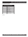
HTH44T— DAILY PRE-OPERATION CHECKLIST
DAILY PRE-OPERATION CHECKLIST
DAILY PRE-OPERATION CHECKLIST
1
Engine oil level.
2
Hydraulic oil level.
3
Radiator coolant level.
4
Condition of blades.
5
Blade pitch operation.
6
Kill switch (seat) operation.
7
Steering control operation.
COMMENTS:
HTH44T • RIDE-ON POWER TROWEL — OPERATION & PARTS MANUAL — REV. #8 (03/27/12) — PAGE 7
— PAGE RM
HTH44T— SAFETY MESSAGE ALERT SYMBOLS
FOR YOUR SAFETY AND THE SAFETY OF OTHERS!
HAZARD SYMBOLS
Safety precautions should be followed at all times when operating
this equipment. Failure to read and understand the Safety
Messages and Operating Instructions could result in injury to
yourself and others.
Lethal Exhaust Gases
Engine exhaust gases contain poisonous
carbon monoxide. This gas is colorless and
odorless, and can cause death if inhaled.
NEVER operate this equipment in a confined
area or enclosed structure that does not
provide ample free flow air.
NOTE
This Owner's Manual has been developed to provide
complete instructions for the safe and efficient operation
of the MQ Whiteman HTH44T Ride-On Power Trowel.
For engine maintenance information, please refer to the
engine manufacturers instructions for data relative to its
safe operations.
Before using this Ride -On Power Trowel, ensure that
the operating individual has read and understands
all instructions in this manual.
Explosive Fuel
Gasoline is extremely flammable, and its
vapors can cause an explosion if ignited. DO
NOT start the engine near spilled fuel or
combustible fluids. DO NOT fill the fuel tank
while the engine is running or hot. DO NOT
overfill tank, since spilled fuel could ignite if it
comes into contact with hot engine parts or
sparks from the ignition system. Store fuel in
approved containers, in well-ventilated areas
and away from sparks and flames. NEVER
use fuel as a cleaning agent.
SAFETY MESSAGE ALERT SYMBOLS
The three (3) Safety Messages shown below will inform you about
potential hazards that could injure you or others. The Safety
Messages specifically address the level of exposure to the
operator, and are preceded by one of three words: DANGER,
WARNING, or CAUTION.
Burn Hazards
DANGER:
You WILL be KILLED or
SERIOUSLY injured if you DO NOT follow
directions.
Engine components can generate extreme heat.
To prevent burns, DO NOT touch these areas
while the engine is running or immediately after
operations. NEVER operate the engine with
heat shields or heat guards removed.
WARNING:
You CAN be KILLED or
SERIOUSLY injured if you DO NOT follow
directions.
Rotating Parts
CAUTION:
You CAN be injured if you
DO NOT follow directions.
NEVER operate equipment with covers, or
guards removed. Keep fingers, hands, hair and
clothing away from all moving parts to prevent
injury.
Potential hazards associated with HTH44T Ride-on Power
Trowel operation will be referenced with Hazard Symbols which
appear throughout this manual, and will be referenced in
conjunction with Safety Message Alert Symbols.
PAGE 8 — HTH44T • RIDE-ON POWER TROWEL — OPERATION AND PARTS MANUAL — REV. #8 (03/27/12)
)
HTH44T— SAFETY MESSAGE ALERT SYMBOLS
Accidental Starting
Respiratory Hazard
ALWAYS place the ON/OFF switch in the
OFF position, and remove the key.
ALWAYS wear approved respiratory
protection.
Over Speed Conditions
Sight and Hearing hazard
NEVER tamper with the factory settings of the
engine governor or settings. Personal injury
and damage to the engine or equipment can
result if operating in speed ranges above
maximum allowable.
NOTE
This Ride-On Power Trowel, other property,
or the surrounding environment could be
damaged if you do not follow instructions.
ALWAYS wear approved eye and hearing
protection.
Equipment Damage Messages
Other important messages are provided throughout this manual
to help prevent damage to your trowel, other property, or the
surrounding environment.
HTH44T • RIDE-ON POWER TROWEL — OPERATION & PARTS MANUAL — REV. #8 (03/27/12) — PAGE 9
— PAGE RM
HTH44T— RULES FOR SAFE OPERATION
■ High Temperatures – Allow the machine
and engine to cool before adding fuel or
performing service and maintenance
functions. Contact with hot components can
cause serious burns.
CAUTION
Failure to follow instructions in this manual may
lead to serious injury or even death! This
equipment is to be operated by trained and
qualified personnel only! This equipment is
for industrial use only and should not be
regarded as a toy.
Emergencies
■ ALWAYS know the location of the
nearest fire extinguisher and first aid kit.
Know the location of the nearest telephone.
Also know the phone numbers of the
nearest ambulance , doctor and fire
department . This information will be
invaluable in the case of an emergency.
The following safety guidelines should always be used when
operating the HTH44T Ride-on Power Trowel:
GENERAL SAFETY
■ DO NOT operate or service this equipment before reading
this entire manual.
Maintenance Safety
■ This equipment should not be operated by persons under
18 years of age.
■ Disconnect the battery and spark plug wires before
attempting any type of service.
■ DO NOT operate this equipment unless all guards and
safety devices are attached and in place.
■ Securely support any machine components that must be
raised.
■ ALWAYS use proper heavy lifting techniques when moving
equipment. This ride-on trowel is very heavy. It should be
lifted only with a lifting device (i.e. crane, forklift, etc.) with
a lifting capacity of at least one ton.
■ NEVER lubricate components or attempt service on a
running machine.
■ ALWAYS allow the machine a proper amount of time to
cool before servicing.
■ ALWAYS check to make sure that the operating area is
clear before starting the engine.
■ Keep the machinery in proper running condition.
■ ALWAYS test the safety kill switch before operating the
equipment.
■ Make sure that there is no buildup of concrete, grease, oil
or debris on the machine.
■ NEVER place your feet inside the guard rings while starting
or operating this equipment.
■ Fix damage to the machine immediately and always replace
broken parts.
■ NEVER operate this equipment without proper protective
clothing, shatterproof glasses, steel-toed boots and other
protective devices required by the job. Avoid wearing
jewelry or loose fitting clothing that may snag on the controls
or moving parts, this can cause a serious injury.
■ Dispose of hazardous waste properly. Examples of
potentially hazardous waste are used motor oil, fuel and
fuel filters.
■ ALWAYS keep clear of rotating or moving parts while
operating this equipment.
■ DO NOT pour waste, oil or fuel directly onto the ground,
down a drain or into any water source.
■ DO NOT use food or plastic containers to dispose of
hazardous waste.
■ NEVER leave the machine unattended while running.
■ ALWAYS refuel in a well-ventilated area, away from sparks
and open flames.
■ ALWAYS use extreme caution when working with
flammable liquids. When refueling, stop the engine and
allow it to cool. DO NOT smoke around or near the machine.
Fire or explosion could result from flames or sparks, or if
fuel is spilled on a hot engine.
■ Moving Parts – Shut down the engine before performing
service or maintenance functions. Contact with moving
parts can cause serious injury.
PAGE 10 — HTH44T • RIDE-ON POWER TROWEL — OPERATION AND PARTS MANUAL — REV. #8 (03/27/12)
)
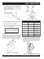
HTH44T— OPERATION AND SAFETY DECALS
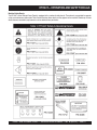
Machine Safety Decals
The HTH44T series Ride-on Power Trowel is equipped with a number of safety decals. These decals are provided for operator
safety and maintenance information. Table 1 below illustrates these decals as they appear on the machine. Should any of these
decals become unreadable, replacements can be obtained from your dealer.
HTH44T • RIDE-ON POWER TROWEL — OPERATION & PARTS MANUAL — REV. #8 (03/27/12) — PAGE 11
— PAGE RM
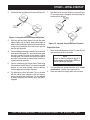
HTH44T— SPECIFICATIONS
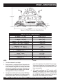
Figure 1. HTH44T Dimension /Specifications
Table 2. HTH-44T Specifications
A–Length – in. (cm)
96.00 (243.8)
B–Width – in. (cm)
50.0 (127)
1
56.0 (142)
C–Height – in. (cm)
Weight – lbs. (kgs.) Operating
1,545 (700)
Weight – lbs. (kgs.) Shipping
1,848 (838)
2
Sound Pressure – dBA
TBA
2
2 3
Vibration – ft/s (m/ s )
TBA
Blade Tip Speed – FPM (m/s)
1924 (9.9)
Engine – H.P.
44
Fuel Tank – gallons (liters)
12 (45)
Rotor – RPM
0 to 160
Path Width – in. (cm)
92 (233)
4
Hydraulic Oil
AW MV 68
Engine
Kubota Diesel V1505-TE
manner
NOTE:
1.
This value includes the seat height.
2.
Sound pressure is a weighted measure. Measured at the
operators ear position while the ride-on trowel is operating
at full throttle on concrete in a manner most often
experienced in “normal” circumstances. Sound pressure
may vary depending upon the condition of the concrete.
Hearing protection is always recommended.
3.
most often experienced in “normal” circumstances.
Values were obtained from all three axes of motion. The
values shown represent the maximum RMS value from
these measurements.
4.
The vibration level indicated is the maximum RMS (Root
Mean Square) value obtained at the handle grip while
operating the ride-on trowel on curing concrete in a
“AW” stands for anti-wear and “MV” stands for multiviscosity. The 68 refers to the general viscosity range
and is similar to 10W-30-motor oil. It is recommended
that AW MV 68 hydraulic oil be used. If this type of
hydraulic oil is not available then use 10W-30.
PAGE 12 — HTH44T • RIDE-ON POWER TROWEL — OPERATION AND PARTS MANUAL — REV. #8 (03/27/12)
)
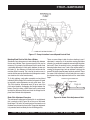
HTH44T— GENERAL INFORMATION
HTH44TRIDE-ON TROWEL FAMILIARIZATION
The HTH44T series Ride-On Power Trowels are designed for
the floating and finishing of concrete slabs.
Take a walk around the HTH44T Ride-On Power Trowel. Take
notice of all the entire major components (see Figures 2 and
3, pages 14 and 15) like the engine, blades, pitch towers, air
cleaner, ignition switch etc. Check that there is always oil in
the engine, and hydraulic oil in the hydraulic oil reservoir.
Dual joystick controls located to the left and right of the operator
are provided for steering the HTH44T Ride-on Power Trowel.
The joysticks are linked to three hydraulic steering cylinders
located within the frame of the machine. When the right side
steering joystick is moved either forward or backward it will
cause that side of the Ride-on Power Trowel to move in either
a forward or reverse direction. Moving the same joystick left
or right causes the trowel to move in either the left or right
direction.
Read all the safety instructions carefully. Safety instructions
will be found throughout this manual and on the machine. Keep
all safety information in good, readable condition. Operators
should be well trained on the operation and maintenance of
the HTH44T Ride-On Power Trowel.
When the left side steering joystick is moved, it will cause the
left side of the Ride-on Power Trowel to travel in either a
forward or reverse direction.
Before using your HTH44T Ride-On Power Trowel, test it on a
flat watered down section of finished concrete. This trial test run
will increase your confidence in using the trowel and at the same
time it will familiarize you with the trowel’s controls and indicators.
In addition you will understand how the trowel will handle under
actual conditions.
Hydraulic Pump
Delivers a continuous controlled flow of hydraulic fluid to the
hydraulic motors.
CAUTION
Engine
This Ride-on Power Trowel is very heavy
and awkward to move around. Use proper
heavy lifting procedures and DO NOT
attempt to lift the Ride-on Power Trowel by
the guard rings
The HTH44T Ride-On Power Trowel is available with a standard
V1505-TE Kubota diesel engine. Refer to the engine owner’s
manual for specific instructions regarding engine operation. This
manual is included with the ride-on trowel at the time of shipping
from Whiteman. Please contact your nearest Multiquip Dealer
for a replacement should the original manual disappear.
Moving the Ride-On Trowel
Blades
The blades of the Ride-on Power Trowel finish the concrete as
they are swirled around the surface. Blades are classified as
float (10 or 8 inches wide), and finish (6 inches wide). The
HTH44T is equipped with five blades per rotor equally spaced
in a radial pattern and attached to vertical rotating shaft by
means of a spider assembly.
Hydraulic Motor
Independent hydrostatic drive motors are coupled to the
engine-powered hydrostatic pumps. Each motor drives a spider
assembly.
Hydraulic Steering
The HTH44T series Ride-on Power Trowel is designed to be
moved and handled several ways. The easiest way to lift the
.ride-on trowel is to utilize the lift loops that are welded to the
frame. These lift loops are located to the left and right sides of
the operator’s seat (Figure 3, Page 15).
A strap or chain can be attached to these lift loops, allowing a
forklift or crane to lift the Ride-on Power Trowel up onto a slab
of concrete. The strap or chain should have a minimum 2,000
pounds (1000-kg) lifting capacity and the lifting gear must be
capable of lifting at least this amount.
Training
For proper training, please use the “TRAINING CHECKLIST”
located in the front of this manual (Page 6). This checklist will
provide an outline for an experienced operator to provide
training to a new operator
HTH44T • RIDE-ON POWER TROWEL — OPERATION & PARTS MANUAL — REV. #8 (03/27/12) — PAGE 13
— PAGE RM
HTH44T— CONTROLS AND INDICATORS
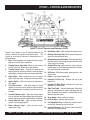
Figure 2. HTH44T Controls and Indicators (Front)
10. Oil Indicator Light - Lights red when oil pressure is low.
Figures 2 and 3 (pages 12 and 13) show the location of the
controls, indicators and general maintenance parts. The
function of each control, indicator or maintenance part is
explained below:
1.
Seat – Place for operator to sit. Engine will not start unless
operator is seated. Seat is adjustable.
2.
Steering Control (right side) -Allows the unit to move
in either a forward, reverse left or right direction.
3.
Throttle Control Lever – Controls the speed of the
engine. Move the hand lever forward to increase engine
speed (high), backwards to decrease engine speed (low).
4.
Light Switch – When activated, turns on six halogen
lights. Lights offer better visibility when working indoors.
5.
Ignition Switch – With key inserted turn clockwise to
start engine.
6.
Twin Pitch Control – Both pitch towers are linked
together. One crank may be turned to adjust the blade
pitch simultaneously or individually control for each set
of blades.
7.
8.
9.
11. Steering Control (left side) -Allows the unit to move in a
forward or reverse direction only.
12. Retardant Spray Control Button – When pressed allows
retardant spray to flow through the spray nozzle located
at the front of the machine.
13. Radiator/Filler Cap –Holds coolant or water necessary
to keep engine at a safe operating temperature. Remove
this cap to add water or antifreeze.
14. Kill Switch - Shuts down engine when operator is not
sitting in seat.
15. Lights – Low voltage halogen light.
16. Hydraulic Oil Filler Cap – Remove this cap to add
hydraulic oil.
17. Hydraulic Oil Sight Glass - Indicates the level of the
hydraulic oil in the reservoir.
18. Right Foot Pedal – Controls blade speed. Slow blade
speed is accomplished by slightly depressing the foot
pedal. Maximum blade speed is accomplished by fully
depressing the foot pedal.
Pre-Heat Indicator Light - Lights blue during engine
start-up. Indicates that engine glow plugs are being preheated. Light will go off after approximately 10 seconds.
19. Spray Nozzle – Spray nozzle for retardant.
20. Left Foot Riser – Operator foot rest pedal.
Charge Indicator Light - Lights red when electrical
system is not charging properly.
21. Fuel Gauge/Filler Cap - Indicates the amount of fuel in
the fuel tank. Remove this cap to add fuel.
Water Indicator Light - Lights red when water
temperature is high.
22. Hydraulic Reservoir – Part of frame. Holds hydraulic oil
necessary for pump operation.
PAGE 14 — HTH44T • RIDE-ON POWER TROWEL — OPERATION AND PARTS MANUAL — REV. #8 (03/27/12)
)
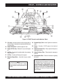
HTH44T— CONTROLS AND INDICATORS
Figure 3. HTH44T Controls and Indicators (Rear)
23. Lift Loops –Located on both the left and right sides of
the main frame. Used when the trowel must be lifted onto
a concrete slab.
29. Retardant Spray Tank - Holds 5 gallons of retardant or
water.
24. Engine Oil Dipstick – Indicates engine oil level.
30. Battery - Provides +12V DC power to the electrical
system.
25. Engine Oil Filler Cap - Remove this cap to add engine
oil.
31. Hydraulic Suction Filter - Filters hydraulic fluid prior to
entering the system.
26. Air Filter – Prevents dirt and other debris from entering
the fuel system.
32. Hydraulic Return Filter - Filters hydraulic returning to
reservoir.
27. Oil Filter – Provides oil filtering for the engine.
33. Documentation Box - Contains information regarding
the trowel.
28. Retardant Spray Motor – Used with the spray control
button.
NOTE
The following section is intended as a basic guide
to the Ride-On Power Trowel operation, and is
not to be considered a complete guide to concrete
finishing. It is strongly suggested that all operators
(experienced and novice) read “Slabs on Grade”
published by the American Concrete Institute,
Detroit Michigan.
NOTE
Read this entire instruction manual
Specification and part number
completely
beforeto
attempting
operate this
are subject
change to
without
machine.
notice.
HTH44T • RIDE-ON POWER TROWEL — OPERATION & PARTS MANUAL — REV. #8 (03/27/12) — PAGE 15
— PAGE RM
HTH44T— INITIAL START-UP
This section is intended to assist the operator with the initial
start-up of the HTH44T series Ride-On Power Trowel. It is
extremely important that this section be read carefully before
attempting to use the trowel in the field.
Fuel
1.
DO NOT use your Ride-On Power Trowel until this section is
thoroughly understood
CAUTION
Determine if the engine fuel is low (Figure
6). If fuel level is low, remove the fuel filler
cap and fill with diesel fuel. Handle fuel
safely. Motor fuels are highly flammable
and can be dangerous if mishandled. DO
NOT smoke while refueling. DO NOT attempt to refuel
the ride-on trowel if the engine is hot or running.
Failure to understand the operation of the
HTH44T series Ride-On Power Trowel could
result in severe damage to the trowel or
personal injury.
See Figures 2 and 3 (Pages 12 and 13) for the location of any
control or indicator referenced in this manual.
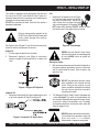
Figure 6. Fuel Gauge
CAUTION
Engine Oil
1.
Pull the engine oil dipstick from its holder.
2.
Determine if engine oil is low (Figure 4), add correct
amount of engine oil to bring oil level to a normal safe
level.
NEVER store the Ride-On Power Trowel
with fuel in the tank for any extended period
of time. ALWAYS clean up spilled fuel
immediately.
Starting the Engine
1.
With one foot on the ground and the other foot placed on
the trowel’s platform, grab hold of any part of the frame
and lift yourself onto the trowel. Then sit down in the
operator’s seat
CAUTION
DO NOT grab hold of the joysticks or pitch
tower assemblies to lift yourself onto the
trowel. Pulling on the joysticks or pitch
towers assemblies repeatedly will weaken
the units. Use any part of the frame to lift
yourself on the trowel.
Figure 4. Engine Oil Dipstick
Hydraulic Oil
1.
2.
Determine if the hydraulic oil is low by observing the level
of oil in the hydraulic Oil Sight Glass (Figure 5).
The Whiteman Ride-On Power Trowel is equipped with
a safety kill switch. This switch is located beneath the
seat assembly. Remember the engine will not start unless
an operator is sitting in the operator’s seat. The weight
of an operator depresses an electrical switch, which will
allow the engine to start.
CAUTION
NEVER disable or disconnect the kill switch.
It is provided for the operators’ safety and
injury may result if it is disabled,
disconnected or improperly maintained.
Figure 5. Hydraulic Oil Sight Glass
PAGE 16 — HTH44T • RIDE-ON POWER TROWEL — OPERATION AND PARTS MANUAL — REV. #8 (03/27/12)
)
HTH44T— INITIAL START-UP
CAUTION
5.
Insert the ignition key into the ignition switch (Figure 8).
NEVER operate the
trowel in a confined area
or enclosed area structure
that does not provide
ample free flow of air.
ALWAYS wear approved eye and hearing
protection before operating the ride-on
power trowel.
Figure 8. Ignition Switch and Key
6.
NEVER place hands or feet inside the guard
rings while the engine is running. ALWAYS
shut the engine down before performing any
kind of maintenance service on the trowel.
Turn the ignition key clockwise to the (start) position. The
oil and charge indicator lights (Figure 9) should be on.
OIL
WA
TE
R
CH
AR
GE
PR
HE E
AT
3.
4.
It is recommended that the kill switch be used to stop the
engine after every use. Doing this will verify that the switch
is working properly and presents no danger to the
operator. Remember to turn the key to the “OFF” position
after stopping the machine. Not doing so may drain your
units’ battery
ON FOR APPROXIMATELY 5-10 SECONDS
WHEN IGNITION SWITCH IS IN THE
PRE HEAT POSITION.
OIL AND CHARGE INDICATOR LIGHTS
COME ON WHEN IGNITION SWITCH IS
IN THE
POSITION.
Figure 9. Oil and Charge Indicator Lights
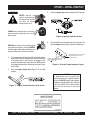
Place the engine throttle lever (Figure 7) in the LOW
position.
Figure 7. Engine Throttle Control Lever (Low)
NOTE
In cold weather turn the ignition key
counter clockwise to the preheat position,
wait until the BLUE preheat indicator goes
off before turning the ignition key clockwise
to the start position. Two or three preheat
cycles may be necessary in very cold
weather.
HTH44T • RIDE-ON POWER TROWEL — OPERATION & PARTS MANUAL — REV. #8 (03/27/12) — PAGE 17
— PAGE RM
HTH44T— INITIAL START-UP
7.
Turn ignition key fully clockwise and listen for engine to
start. Once engine has started release ignition key. Let
engine warm for a few minutes.
8.
Place the engine throttle lever (Figure 10) in the HIGH
position.
Figure 12. Right Joystick
Table 3. Joystick Directional Positioning
DIRECTION
RESULTS
Causes only the left side
Left
Move Joystick Forward
of the ride-on trowel to
move forward.
Causes only the left side
Left
Move Joystick Backward
of the ride-on trowel to
move backward.
Causes only the right side
Right
Move Joystick Forward
of the ride-on trowel to
move forward.
Causes only the right side
of the ride-on trowel to
Right
Move Joystick Backward
move backward.
Causes the ride-on trowel
M
o
v
e
B
o
t
h
Left and Right
to move forward in
Joysticks Forward
a straight line.
JOYSTICK
Figure 10. Engine Throttle Control Lever (High)
9.
The engine should be running at full RPM.
10. Repeat this section a few times to get fully acquainted
with the engine starting procedure.
NOTE
All directional references with respect to
the joysticks are from the operator’s seat
position.
Steering
Two joysticks (Figures 11 and 12) located to the left and right of
the operator’s seat provide directional control for the HTH44T
Ride-On Power Trowel. Table 3 illustrates the various directional
positions of the joysticks and their effect on the ride-on trowel.
1.
Left and Right
Move Both
Joysticks Backward
Right
Move Joystick Right
Right
Move Joystick Left
Causes the ride-on trowel
to move backward
in a straight line.
Causes the ride-on trowel
to move to the right.
Causes the ride-on trowel
to move to the left
The foot pedal (Figure 13) solely controls blade speed.
The position of the foot pedal determines the blade speed.
Slow blade speed is obtained by slightly depressing the
pedal. Maximum blade speed is obtained by fully
depressing the pedal.
Figure 11. Left Joystick Control
Figure 13. Blade Speed Control Foot Pedal
PAGE 18 — HTH44T • RIDE-ON POWER TROWEL — OPERATION AND PARTS MANUAL — REV. #8 (03/27/12)
)
HTH44T— INITIAL START-UP
2.
Push both the left and right joysticks forward (Figure 14).
7.
Push both the left and right joysticks backward (Figure
15) and repeat steps 3 through 6 while substituting the
word reverse for forward.
Figure 14. Joystick Control Forward Direction
3.
4.
5.
6.
With your right foot slowly depress the right foot pedal
halfway. Notice that the ride-on power trowel begins to
move in a forward direction. Release both joystick controls
to stop forward movement then remove your right foot
from the right foot pedal.
Practice holding the machine in one place as you increase
blade speed. When about 75% of maximum blade speed
has been reached, the blade will be moving at proper
finishing speed. The machine may be difficult to keep in
one place. Trying to keep the ride-on trowel stationary is
a good practice for operation.
Practice maneuvering the Ride-on Power Trowel using
the information listed in Table 3. Try to practice controlled
motions as if you were finishing a slab of concrete.
Practice edging and covering a large area
Try adjusting the pitch of the blades. This can be done
with the ride-on trowel stopped or while the trowel is
moving, whatever feels comfortable. Test the operation
of optional equipment like retardant spray and lights if
equipped.
Figure 15. Joystick Control Reverse Direction
Engine Shut-Down
1.
Return the speed control lever (Figure 7) to low idle, and
allow the engine to idle for 5 minutes .
NOTE
Failure to allow the engine to idle for 5
minutes before shutting engine OFF may
lead to turbocharger damage.
2.
3.
Turn the ignition key counter-clockwise to the "starter
switch contact " position, then remove the key.
Clean and remove any foreign debris from the trowel.
HTH44T • RIDE-ON POWER TROWEL — OPERATION & PARTS MANUAL — REV. #8 (03/27/12) — PAGE 19
— PAGE RM
HTH44T— MAINTENANCE
MAINTENANCE PROCEDURES
NOTE
Checking/Adjusting Blade Speed
See the engine manual supplied with your
machine for appropriate engine maintenance
schedule and troubleshooting guide for
problems.
Because the two hydraulic drive motors operate independent
of each other, the blade speed between them may vary. If the
unit’s steering is difficult to control, the blade speeds may need
to be checked, or if the spider is spinning noticeably faster or
slower than the other side, the blade speed may need to be
checked. It is also recommended that the blade speed be
checked at least once a year.
At the front of the book (Page 7) there is a “Daily Pre-Operation
Checklist”. Make copies of this checklist and use it on a daily
basis.
Blade speed adjustment is a two-step process. First, the left
spider’s speed should be checked and/or adjusted. Second,
the right spider’s speed should be adjusted to match the left.
CAUTION!
Disconnect spark plug
wires and battery cables
before attempting any
service or maintenance on
the Ride-on Power Trowel.
ALWAYS allow the engine to cool before
servicing. NEVER attempt any maintenance
work on a hot! (muffler, radiator, etc.) trowel.
MAINTENANCE SCHEDULE
Left Spider Speed Adjustment
The left spider’s speed is adjusted by changing the length of
the rod end spacing (Figure 16) at the front of the foot pedal.
Lengthening the spacing increases the blade speed;
shortening the spacing decreases the blade speed.
Change the hydraulic oil and filter after the first 100 hours
of use, then change every 250 hours.
Daily (8-10 Hours)
1.
Check the fluid levels in the engine and reservoir, fill as
necessary.
Weekly (30-40 Hours)
1.
Relube arms, thrust collar and clutch
2.
Replace blades if necessary.
Right Spider Speed Adjustment
3.
Check and clean or replace the engine air filter as
necessary.
4.
Replace engine oil and filter as necessary, see engine
manual.
The right spider’s speed is adjusted by changing the length of
the connecting rod on the pump actuation levers (Figure 17,
Page 21). This rod is basically a turnbuckle. Rotating it in one
direction increases the length and corresponding spider speed.
Rotating it the opposite direction decreases the length and
spider speed. The right spider’s speed should be within 3 rpm
of the left.
Figure 16. Blade Speed Control Foot Pedal
Monthly (100-125 Hours)
1.
Remove, clean, reinstall and relube the arms and thrust
collar. Adjust the blade arms.
A good starting point in the adjustment process is to adjust
the rod such that both spiders begin to rotate at the same time
when the foot pedal is slowly depressed. This will, generally,
get the speeds fairly close. Close enough for use if
instrumentation is unavailable (i.e. on the job site). From this
point on, some form of instrumentation is required to verify
that the right spider speed is within the tolerance specified
above. A strobe or magnetic pickup type speed indicator is
recommended to verify the speeds.
Yearly (500-600 Hours)
1.
Check and replace if necessary the arm bushings, and
thrust collar bushings.
2.
Check pitch control cables for wear.
3.
Adjust blade speed.
4.
Replace hydraulic fluid and both hydraulic filters.
NOTE
Change the hydraulic oil and filter after
the first 100 hours of use, then change
every 250 hours.
The speeds should be adjusted on a dry concrete floor with
the blades pitched flat. Units with a Kubota turbocharged
engine should be set at 155-160 rpm with the engine at full
speed.
PAGE 20 — HTH44T • RIDE-ON POWER TROWEL — OPERATION AND PARTS MANUAL — REV. #8 (03/27/12)
)
HTH44T— MAINTENANCE
Figure 17. Pump Actuation Levers/Speed Control Rod
Matching Blade Pitch for Both Sets of Blades
Sometimes it may be necessary to match blade pitch between
the two sets of blades. There are some signs that this may be
necessary. For example, the differences in pitch could cause
a noticeable difference in finish quality between the two sets
of blades. Or, the difference in blade pitch could make the
machine difficult to control. This is due to the surface area in
contact with the concrete (the blade set with the greater contact
area tends to stick to the concrete more).
To fix this problem, each spider assembly can be pitched
individually. With a Single Pitch machine, the operator is forced
to constantly make adjustments on each pitch tower. On a
Twin Pitch machine, the operator must lift up on one of the
pitch control handles, disengaging the linkage between the
towers. Once this is done, a pitch control crank can be turned
to adjust the difference. Make sure to lock the linkage back in
place when finished with adjustments.
There are some things to look for when checking to see if
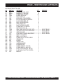
adjustment is necessary. Is the machine wearing out blades
unevenly (i.e. one blade is completely worn out while the others
look new)? Does the machine have a perceptible rolling or
bouncing motion when in use? Look at the machine while it is
running, do the guard rings “rock up and down” relative to the
ground? Do the pitch control towers rock back and forth? These
are some of the indications that the blade pitch may need to
be adjusted using the adjustment bolts on the trowel blade
finger.
Blade Pitch Adjustment Procedure
Figure 18. Blade Pitch Adjustment Bolt
The maintenance adjustment of blade pitch is an adjustment
that is made by a bolt (Figure 18) on the arm of the trowel
blade finger. This bolt is the contact point of the trowel arm to
the lower wear plate on the thrust collar. The goal of adjustment
is to promote consistent blade pitch and finishing quality.
HTH44T • RIDE-ON POWER TROWEL — OPERATION & PARTS MANUAL — REV. #8 (03/27/12) — PAGE 21
— PAGE RM
HTH44T— MAINTENANCE
Changing A Blade
The easiest and most consistent way to make this adjustment
is to use the Trowel Arm Adjustment Fixture (P.N. 9177) that is
manufactured by Whiteman. This fixture will allow consistent
adjustment of the trowel arm fingers. It comes with all the
hardware necessary to properly accomplish this maintenance
and instructions on how to properly utilize this tool. Adjusting
the trowel arm fingers without a fixture requires a special talent.
Whiteman recommends that all the blades on the entire
machine be changed at the same time. If only one or some of
the blades are changed at one time, the machine will not finish
concrete consistently and the machine may wobble or bounce.
If a trowel arm adjustment fixture is not available and immediate
adjustment is necessary; we suggest the following procedure.
If you can see or feel which blade is pulling harder, adjust the
bolt that corresponds to that blade. Another way to determine
which blades need adjustment is to place the machine on a
flat surface and pitch the blades as flat as possible. Now, look
at the adjustment bolts. They should all barely make contact
with the lower wear plate on the spider. If you can see that
one of them is not making contact; some adjustment will be
necessary.
It will be possible to adjust the “high” bolts down to the level of
the one that is not touching, or adjust the “low” bolt up to the
level of the higher ones. If possible, adjust the low bolt up to
the level of the rest of the bolts. This is the fastest way, but
may not always work. Verify that after adjustment, the blades
pitch correctly. Often times, if the blades are incorrectly
adjusted, they will not be able to pitch flat. This occurs when
the adjusting bolts have been raised too high. Conversely,
sometimes the adjusting bolts are too low and the blades
cannot be pitched high enough for finishing operations.
1.
Place the machine on a flat, level surface. Adjust the blade
pitch control to make the blades as flat as possible. Note
the blade orientation on the trowel arm. This is important
for ride-on trowels as the two sets of blades counterrotate. Lift the machine up, placing blocks under the main
guard ring to support it.
2.
Remove the bolts and lock washers on the trowel arm,
and then remove the blade.
3.
Scrape all concrete and debris from the trowel arm. This
is important to properly seat the new blade.
4.
Install the new blade, maintaining the proper orientation
for direction of rotation.
5.
Affix the bolts and lock washers.
6.
Repeat steps 2-5 for all remaining blades.
PAGE 22 — HTH44T • RIDE-ON POWER TROWEL — OPERATION AND PARTS MANUAL — REV. #8 (03/27/12)
)
HTH44T— MAINTENANCE
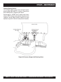
Checking Hydraulic Pressure
It should be mentioned that most hydraulic problems are a
result of low fluid levels. Before checking any other possibilities,
make sure the hydraulic fluid level is half way up the sight
glass which is located at the right end of the frame.
Hydraulic pressure can be checked using a pressure gauge
(Figure 19) with a range of at least 5,000 psi. Two male
diagnostic quick couplers (one for each pump) are located in
the elbow fittings (Figure 19) at the front of the pump. It is best
to use two gauges simultaneously, but it is possible to use
only one gauge and repeat the procedure for each side.
To fully test the hydraulic system, the spiders will need to be
locked so that they cannot rotate. This can easily be done by
wrapping a chain around an arm on each spider, thus chaining
them together in the back of the trowel.
Once the pressure gauges are installed and the spiders chained
together, the system can be checked.
With the foot pedal in the idle position and the engine at full
speed, the pressure should be 200 to 300 psi. If the pressure
is less than 200 psi, the charge system may need to be
inspected and/ or serviced. In particular, the suction filter and
charge pump relief valve should be checked. The suction filter
may be plugged, or the relief valve may be stuck. Either
condition may cause low charge pressure.
With the engine at 50% to 70% of full speed, and spiders
chained together, slowly depress the foot pedal and read the
gauges. The pressure should get to at least 3,100 psi. If the
pressure will not attain 3,100 psi, the pump should be inspected
and/or serviced by an authorized service representative.
Figure 19. Pressure Gauge (Hydraulic Pump)
HTH44T • RIDE-ON POWER TROWEL — OPERATION & PARTS MANUAL — REV. #8 (03/27/12) — PAGE 23
— PAGE RM
HTH44T— MAINTENANCE
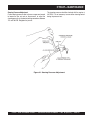
Checking Steering Pressure
Lift the hinged radiator access cover and insert the test
pressure gauge (300 to 600 PSI) as shown in Figure 20 into
the left steering valve's diagnostic quick coupler.
Run the engine at full RPM. The left steering valve's factory
setting is 145 PSI, however some operators may prefer a more
responsive steering (higher pressure required) and some
operators may prefer a "softer feel" (lower pressure required).
Figure 20. Pressure Gauge (Left Steering Valve)
PAGE 24 — HTH44T • RIDE-ON POWER TROWEL — OPERATION AND PARTS MANUAL — REV. #8 (03/27/12)
)
HTH44T— MAINTENANCE
Steering Pressure Adjustment
On the steering pressure relief valve use an open-end wrench
to loosen the jam nut and an allen-wrench to adjust the
steering pressure to the desired setting somewhere between
115 and 180 PSI. Retighten the jam nut.
The steering pressure should be checked with the engine at
full RPM. It is not necessary to move either steering control
during the pressure test.
Figure 21. Steering Pressure Adjustment
HTH44T • RIDE-ON POWER TROWEL — OPERATION & PARTS MANUAL — REV. #8 (03/27/12) — PAGE 25
— PAGE RM
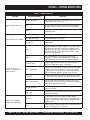
HTH44T— TROUBLESHOOTING
TABLE 4. TROUBLESHOOTING
SYMPTOM
Engine running rough or not at
all.
Safety kill switch not functioning.
If trowel “bounces, rolls
concrete, or makes uneven
swirls in concrete”.
POSSIBLE PROBLEM
SOLUTION
Kill switch malfunction?
Make sure that the kill switch is functioning when the operator is
seated; replace switch if necessary.
Fuel?
Look at the fuel system. Make sure there is fuel being supplied to
the engine. Check to ensure that the fuel filter is not clogged.
Ignition?
Check to ensure that the ignition switch has power and is
functioning correctly.
Other problems?
Consult engine manufacturer’s manual.
Loose wire connections?
Check wiring. Replace as necessary.
Bad contacts?
Replace switch.
Blades?
Make cer tain blades are in good condition, not excessively worn.
Finish blades should measure no less than 2" (50mm) from the
blade bar to the trailing edge, combo blades should measure no
less that 3.5" (89mm). Trailing edge of blade should be straight
and parallel to the blade bar.
Spider?
Check that all blades are set at the same pitch angle as
measured at the spider. A field adjustment tool is available for
height adjustment of the trowel arms (see Optional Equipment).
Bent trowel arms?
Check the spider assembly for bent trowel arms. If one of the
arms is even slightly bent, replace it immediately.
Trowel arm bushings?
Check the trowel arm bushings for tightness. This can be done by
moving the trowel arms up and down. If there is more than 1/8"
(3.2 mm) of travel at the tip of the arm, the bushings should be
replaced. All bushings should be replaced at the same time.
Thrust collar?
Check the flatness of the thrust collar by rotating it on the spider.
If it varies by more than 0.02" (0.5 mm) replace the thrust collar.
Thrust collar bushing?
Check the thrust collar by rocking it on the spider. If it can tilt
more than 1/16" (1.6 mm) [as measured at the thrust collar O.D.],
replace the bushing in the thrust collar.
Thrust bearing worn?
Check the thrust bearing to see that it is spinning free.
Replace if necessary.
Blade pitch?
Check blades for consistent pitch. Adjust per Maintenance section
instructions if necessary.
Main shaft?
The main output shaft of the gearbox assembly should be
checked for straightness. The main shaft must run straight and
cannot be more than 0.003" (0.08 mm) out of round at the spider
attachment point.
Yoke?
Check to make sure that both fingers of the yoke press evenly on
the wear cap. Replace yoke as necessary.
Machine has a perceptible
rolling motion while running.
PAGE 26 — HTH44T • RIDE-ON POWER TROWEL — OPERATION AND PARTS MANUAL — REV. #8 (03/27/12)
)
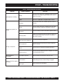
HTH44T— TROUBLESHOOTING
TABLE 4. TROUBLESHOOTING (CONTINUED)
SYMPTOM
POSSIBLE PROBLEM
SOLUTION
Wiring?
Check all electrical connections, including the master on/off switch
and check to see if wiring is in good condition with no shor ts.
Replace as necessary.
Lights?
Check to see if light bulbs are still good. Replace if broken.
Retardant?
Check the tank to make sure retardant is present. Fill tank as
necessary.
Wiring?
Check all electrical connections, including master on/off switch
connections. Replace components and wiring as necessary.
Lights (optional) not working.
Retardant spray (optional) not
working.
Check the continuity of master on/off switch. Replace if broken.
Bad switch?
Bad spray pump?
If pump has a voltage present when the switch is turned on, but
does not operate and electrical connections to the pump are
good, replace the pump.
Blade speed out of adjustment?
See section on blade speed adjustment.
Worn components?
Check for wear of steering bearings and linkage components
replace if necessary.
Pivots?
Check to ensure free movement of hydraulic drive motors.
Hydraulic pressure?
Check to ensure that hydraulic pressure is adequate. See section
on checking hydraulic pressure.
Steering is unresponsive.
Operating position is
uncomfor table.
Seat adjust for operator?
Crank handles?
Adjust seat with lever located on the front of the seat.
Make sure that both crank handles are pushed down as far as
possible. Doing this ensures that the linkage is engaged.
Linkage on Twin Pitch (optional)
not working.
Broken par t?
Replace all broken par ts immediately.
HTH44T • RIDE-ON POWER TROWEL — OPERATION & PARTS MANUAL — REV. #8 (03/27/12) — PAGE 27
— PAGE RM
HTH44T— EXPLANATION OF CODE IN REMARKS COLUMN
The following section explains the different symbols and
remarks used in the Parts section of this manual. Use the
help numbers found on the back page of the manual if there
are any questions.
QTY. Column
Numbers Used — Item quantity can be indicated by a
number, a blank entry, or A/R.
A/R (As Required) is generally used for hoses or other
parts that are sold in bulk and cut to length.
NOTICE
The contents and part numbers listed in the parts
section are subject to change without notice. Multiquip
does not guarantee the availability of the parts listed.
A blank entry generally indicates that the item is not sold
separately. Other entries will be clarified in the “Remarks”
Column.
SAMPLE PARTS LIST
NO.
1
2%
2%
3
4
REMARKS Column
PART NO. PART NAME
QTY. REMARKS
12345
BOLT......................1 .....INCLUDES ITEMS W/%
WASHER, 1/4 IN............NOT SOLD SEPARATELY
12347
WASHER, 3/8 IN....1 .....MQ-45T ONLY
12348
HOSE ..................A/R ...MAKE LOCALLY
12349
BEARING ..............1 .....S/N 2345B AND ABOVE
Some of the most common notes found in the “Remarks”
Column are listed below. Other additional notes needed
to describe the item can also be shown.
Assembly/Kit — All items on the parts list with the
same unique symbol will be included when this item is
purchased.
NO. Column
Unique Symbols — All items with same unique
symbol
Indicated by:
“INCLUDES ITEMS W/(unique symbol)”
(@, #, +, %, or >) in the number column belong to the
same assembly or kit, which is indicated by a note in the
“Remarks” column.
Serial Number Break — Used to list an effective serial
number range where a particular part is used.
Indicated by:
“S/N XXXXX AND BELOW”
“S/N XXXX AND ABOVE”
“S/N XXXX TO S/N XXX”
Duplicate Item Numbers — Duplicate numbers indicate
multiple part numbers, which are in effect for the same
general item, such as different size saw blade guards in
use or a part that has been updated on newer versions
of the same machine.
Specific Model Number Use — Indicates that the part
is used only with the specific model number or model
number variant listed. It can also be used to show a
part is NOT used on a specific model or model number
variant.
NOTICE
When ordering a part that has more than one item
number listed, check the remarks column for help in
determining the proper part to order.
Indicated by:
“XXXXX ONLY”
“NOT USED ON XXXX”
PART NO. Column
Numbers Used — Part numbers can be indicated by a
number, a blank entry, or TBD.
“Make/Obtain Locally” — Indicates that the part can
be purchased at any hardware shop or made out of
available items. Examples include battery cables, shims,
and certain washers and nuts.
TBD (To Be Determined) is generally used to show a
part that has not been assigned a formal part number
at the time of publication.
“Not Sold Separately” — Indicates that an item cannot
be purchased as a separate item and is either part of an
assembly/kit that can be purchased, or is not available
for sale through Multiquip.
A blank entry generally indicates that the item is not sold
separately or is not sold by Multiquip. Other entries will
be clarified in the “Remarks” Column.
PAGE 28 — HTH44T • RIDE-ON POWER TROWEL — OPERATION AND PARTS MANUAL — REV. #8 (03/27/12)
)
HTH44T— SUGGESTED SPARE PARTS & SERVICE ITEMS
HTH44T SERIES - KUBOTA 44 HP TURBO ENGINE
1 Unit
Qty.
P/N
Description
5 ............ 2829 ................ ARMS
2 ............ 9005 ................ LEVER TROWEL ARM (L.S.)
20 .......... 0166A .............. WASHER
20 .......... 1876 ................ JAM NUT
20 .......... 0164B .............. SCREW
5 ............ 11039 ............... BUSHING
2 ............ 9111 ................. SPRING (L.S.)
20 .......... 1875 ................ WASHER
20 .......... 1322 ................ SCREW ASM, ARM RETAINING
2 ............ 11419 ............... SPIDER PLATE (WEAR)
20 .......... 1162A .............. CAP GREASE FITTING
20 .......... 16602............... SCREW (HHC 3/8 -16 X 3/8)
2 ............ 2143 ................ SPRING (R.S.)
2 ............ 1986 ................ LEVER TROWEL ARM (R.S.)
2 ............ 12005............... SAFETY-OFF ("KILL" SWITCH)
20 .......... 0181B .............. WASHER 1/4 IN
1 ............ 11418 ............... FUEL CAP/GAUGE (ENG)
1 ............ 12010............... FUEL SCREEN
2 ............ 19633............... BUSHING, RUBBER FUEL
1 ............ 12332............... CAP, HYDRAULIC RESEVOIR
1 ............ 11402 ............... FILTER, HYDRAULIC RETURN
1 ............ 20567............... FILTER, HYDRAULIC SUCTION
1 ............ EATON 70142-938 SEAL KIT (EATON HYD PUMP)
1 ............ 12238............... KEY, SHAFT
1 ............ EATON 61295 .. SEAL KIT, REAR (PORT END)
1 ............ 12313............... SEAL, INPUT SHAFT
1 ............ EATON 61338-000 SEAL KIT, (HYD MOTOR)
1 ............ 11874 ............... GROMMET, (HYD PUMP LEVER)
1 ............ 20003............... ROD END, FEM (HYD PUMP LEVER)
4 ............ 11577 ............... PLATE, VIBRATION MOUNT (ENG)
1 ............ 11491 ............... CABLE, THROTTLE (FOOT PEDAL)
1 ............ 11611 ............... ROD END, FEM RH (HYD THROTTLE)
1 ............ 2153 ................ ROD END, FEM RH(THROTTLE CABLE)
1 ............ 11643 ............... ROD END, MALE (RH)
1 ............ 12548............... SPRAY PUMP
1 ............ 392292............. SPRAY NOZZEL
1 ............ 19633............... BUSHING, RUBBER FUEL
1 ............ 2108 ................ CAP, SPRAY TANK
1 ............ 12009............... SCREEN FILTER
10 .......... 10031............... WASHER, 1/4"
Qty.
P/N
Description
1 ............ 19638 .................... BRACKET BATTERY
2 ............ 11693 .................... BOLT BATTERY BRACKET
1 ............ 10314 .................... CABLE, BATTERY+ (RED)
1 ............ 10313 .................... CABLE, BATTERY-(BLACK)
1 ............ 1597 ..................... CABLE, (NEG 16.5")
6 ............ 2509 ..................... WING NUT
1 ............ 20511 .................... SWITCH, IGNITION
1 SET .... 12627 .................... KEYSET, IGNITION
2 ............ 12307 .................... BULB, INDICATOR LIGHT
1 ............ 11585 .................... INDICATOR PLUG (BLUE)
1 ............ 11382 .................... INDICATOR PLUG (RED)
1 ............ 11098 .................... CIRCUIT BREAKER 40 AMP, 12V
1 ............ 4682 ..................... TOGGLE SWITCH
1 ............ 8381 ..................... BOOT, TOGGLE SWITCH
1 ............ 11792 .................... ACCESSORY SOLENOID
1 ............ 11694 .................... HOUR METER
PARTS FOR KUBOTA 44 HP TURBO ENGINE
Qty.
P/N
Description
1 ............ KUBOTA P/N 16271-32090 OIL FILTER
1 ............ KUBOTA P/N 17351-11083 AIR FILTER ELEMENT
1 ............ 70000-43081 ... FUEL FILTER
1 ............ 16282-97010 ... FAN BELT
2 ............ 16241-72870 ... RADIATOR HOSE
4 ............ 36200-82720 ... HOSE CLAMP
1 ............ 20295 ............... MUFFLER HTH44
1 ............ 20122 ............... MUFFLER BLANKET
1 ............ 20318 ............... MUFFLER KIT, KUBOTA VI505-TE
1 ............ 10434 ............... CLAMP, HOSE 2"
1 ............ 20112 ............... BRACKET, ENGINE THROTTLE CABLE
1 ............ 10568 ............... THROTTLE CABLE (ENGINE)
1 ............ 11531 ............... BELLHOUSING, KUBOTA VH 1305/150
1 ............ 11605 ............... FLANGE, ENG KTR NYLON
1 ............ 20316 ............... FAN, PUSHER, KUBOTA
1 ............ 20320 ............... RADIATOR KIT, KUBOTA VI505-TE
1 ............ 11983 ............... TANK, RADIATOR OVERFLOW
1 ............ 20327 ............... AIR CLEANER KIT, KUBOTA VI505-TE
1 ............ 20566 ............... HARNESS, WIRE 44HP ENGINE(HTH)
1 ............ 20322 ............... HARNESS, WIRE KUBOTA 44T
1 ............ 20321 ............... MANUAL, KUBOTA OWNERS, VI505-TE
NOTE
Part numbers on this Suggested
Spare Parts List may supercede/
replace the P/N shown in the text
pages of this book.
HTH44T • RIDE-ON POWER TROWEL — OPERATION & PARTS MANUAL — REV. #8 (03/27/12) — PAGE 29
— PAGE RM
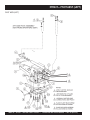
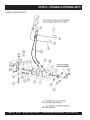
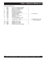
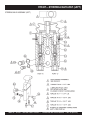
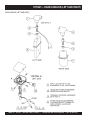
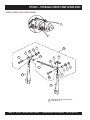
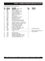
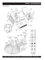
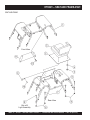
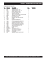
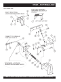
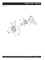
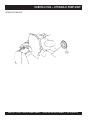
HTH44T— PIVOT ASSY. (LEFT)
PIVOT ASSY. (LEFT)
PAGE 30 — HTH44T • RIDE-ON POWER TROWEL — OPERATION AND PARTS MANUAL — REV. #8 (03/27/12)
)
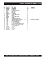
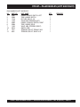
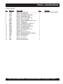
HTH44T— PIVOT ASSY. (LEFT)
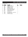
PIVOT ASSY. (LEFT)
NO.
1
2
3
4
5
6
7
8
9
10
11
12
13
14
15
16
17
PART NO.
12968
11499
10221
11555
0166A
1023
0183
11648
0448
12983
3214
13178
11882
10176
20002
11772
11773
PART NAME
QTY.
REMARKS
MOUNT, HYD. MOTOR LEFT
1
YOKE
1
BUSHING
2
ROCKER BLOCK
2
WASHER, LOCK 3/8 MED.
4
SCREW, HHC 3/8- 16 X 1- 1/4
4
PIN,COTTER 1/8 1- 1/4
2
PIN, PIVOT
1
WASHER, FLAT 7/16 SAE
2
MOUNT, HYD. MOTOR BOTTOM ........................ 1 ............... DOES NOT INCL ITEM 2, YOKE
SCREW, HHC 1/2- 13 X 1- 1/4
4
SCREW, HHC 1/2- 13 X 2 1/4
2
SCREW, FHSC 1/2- 13 X 2 1/4
2
NUT, NYLOC 1/2- 13
8
MOTOR, EATON VIS30 24CID
1
SHIM .................................................................. AR
SHIM .................................................................. AR
HTH44T • RIDE-ON POWER TROWEL — OPERATION & PARTS MANUAL — REV. #8 (03/27/12) — PAGE 31
— PAGE RM
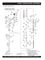
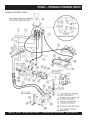
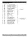
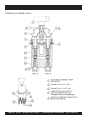
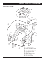
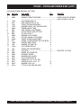
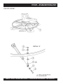
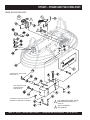
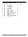
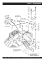
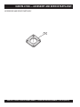
HTH44T— PIVOT ASSY. (RIGHT)
PIVOT ASSY. (RIGHT)
PAGE 32 — HTH44T • RIDE-ON POWER TROWEL — OPERATION AND PARTS MANUAL — REV. #8 (03/27/12)
)
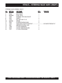
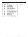
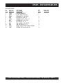
HTH44T— PIVOT ASSY. (RIGHT)
PIVOT ASSY. (RIGHT)
NO.
1
2
3
4
5
6
7
8
9
10
11
12
13
14
15
16
17
18
19
20
21
PART NO.
12967
11450
10221
11555
0166A
1023
0183
11648
0448
12983
3214
13178
11882
11499
10176
11154
10138
11420
20002
11772
11773
PART NAME
QTY.
REMARKS
MOUNT, HYD. MOTOR RIGHT
1
TRUNNION
1
BUSHING
4
ROCKER BLOCK
2
WASHER, LOCK 3/8 MED.
6
SCREW, HHC 3/8- 16 X 1- 1/4
6
PIN, COTTER 1/8 1- 1/4
2
PIN, PIVOT
1
WASHER, FLAT 7/16 SAE
2
MOUNT, HYD. MOTOR BOTTOM ........................ 1 ............... DOES NOT INCLUDE ITEM 14
SCREW, HHC 1/2- 13 X 1- 1/4
4
SCREW, HHC 1/2- 13 X 2 1/4
2
SCREW, FHSC 1/2- 13 X 2 1/4
2
YOKE
1
NUT, NYLOC 1/2- 13
8
RETAINER, CLUTCH
2
SCREW, SHS 1/4- 20 X 1/2, N.P.
1
SHAFT, PIVOT
1
MOTOR, EATON VIS30 24CID
1
SHIM .................................................................. AR
SHIM .................................................................. AR
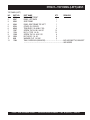
20
21
11772
11773
SHIM
SHIM
(USE AS REQUIRED)
(USE AS REQUIRED)
HTH44T • RIDE-ON POWER TROWEL — OPERATION & PARTS MANUAL — REV. #8 (03/27/12) — PAGE 33
— PAGE RM
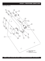
HTH44T— TWIN PITCH ASSY. (LEFT/RIGHT)
LEFT/RIGHT TWIN PITCH ASSY.
PAGE 34 — HTH44T • RIDE-ON POWER TROWEL — OPERATION AND PARTS MANUAL — REV. #8 (03/27/12)
)
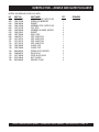
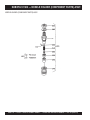
HTH44T— TWIN PITCH ASSY. (LEFT/RIGHT)
LEFT/RIGHT TWIN PITCH ASSY.
HTH44T • RIDE-ON POWER TROWEL — OPERATION & PARTS MANUAL — REV. #8 (03/27/12) — PAGE 35
— PAGE RM
HTH44T— TWIN PITCH ASSY. (LEFT/RIGHT)
LEFT/RIGHT TWIN PITCH ASSY.
NO
1+%
2+%
3 +%
*
4+%
5+%
6+%
7+%
8+
9+%
10+%
11+
12+%
13+%
14 +%
*
15 +%
*
16+%
17
18
19+%
20 +%
*
22+%
23+%
24 +%
*
25+%
26+%
27+%
28+%
29 +%
*
30+%
31
32
33+%
34+%
35+%
36+%
37+%
38 +%
*
40+%
PART NO
0126 B
0161C
0181 B
0655
0685
0948
10382
10511
10512
10546
10722
10723
1116
11583
1162 A
11623
11630
11649
11652
11654
1529
1530
1578
1579
1586
1604
1612
1733
2007
2012
2156
2169
2170
2311
2367
2620
2621
2649
PART NAME
KEY, WOODRUFF #9
WASHER, LOCK 5/16 MED
WASHER, LOCK, 1/4 MED
SCREW, HHC 5/16 – 18 X 3/4
SCREW, SHS 5/16 – 18 X 5/16
WASHER, FLAT, 1/4 SAE
BOLT, SHOULDER, 3/8 X 3/8 LONG
SHAFT, PITCH CONTROL, LH TPC
RING, SNAP, TRUARC 5160 – 75
HOUSING, PITCH CONTROL, 1-3/4
SLIDE BLOCK, LH PITCH CON
PIN, SPIROL 3/16 X 1 3/8 HD
NUT, BRASS JAM 5/16 – 18
U-JOINT, PITCH CONTROL
CAP, GREASE ZERK, #2 YELLOW
CABLE, PITCH ASM
TUBE, PITCH CONTROL
SPACER, PITCH SPRING
SHAFT, TWIN PITCH
PIN, ROLL 1/8 Z 1 PLATED
GEAR, MASTER, TPC
GEAR, SLAVE, TPC
KEY, WOODRUFF, #3
SCREW, HHC 1/4 – 20 X 1/2
PIN, ROLL 1/8 X 3/4
BEARING, BALL
BEARING, ALUM – PITCH CONTR
WASHER, 1/32 X 1/2 HARDENED
SHAFT
SLEEVE, ADJ – LONG, RIDER
SPRING, COIL
BEARING, THRUST, TORR #NTA 1220
BEARING, RACE, TORR #TRA 1220
SPACER, 3/4 X 1/2 X 8L
SET COLLAR
SCREW, BHC 10 – 24 X 5/8
ZERK, GREASE STR 1/4 – 28
COVER, PITCH CONT HOUSING
QTY.
1
3
1
3
1
1
1
1
1
1
1
1
2
1
1
1
1
1
1
2
1
1
1
1
1
1
1
6
1
1
1
1
3
1
1
4
1
1
REMARKS
PAGE 36 — HTH44T • RIDE-ON POWER TROWEL — OPERATION AND PARTS MANUAL — REV. #8 (03/27/12)
)
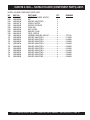
HTH44T— TWIN PITCH ASSY. (LEFT/RIGHT)
LEFT/RIGHT TWIN PITCH ASSY.
NO
41
42
43
*
44
*
45
*
46
*
47
*
48
*
49
*
50
*
51
*
52
*
53
54
55
*
56
57
58#
59#
60#
61#
62#
63#
64#
65#
66#
67#
68%
69%
70
PART NO
0202
0300 B
0730
11653
1577
1987
1988
2021
2022
2062
2845
4514
5283
11650
11651
11655
1617
2300
2332
4014
4403
3231
1615
1733
1616
0185
1528
10510
10721
2737
PART NAME
QTY.
REMARKS
SCREW, HHC 5/16 – 18 X 1
8
WASHER, FLAT, 5/16 SAE
8
SCREW, HHC 1/4 – 20 X 1
16
SLEEVE, W/U-JOINT
1
SET COLLAR, 1/2
4
MITER BOX, PITCH CONTROL
2
MIT BOX, BEARING CAP RIDERS
4
SHAFT, MITER VERT JRT
2
SHAFT, MITER VERTICAL
3
GEAR, MITER, TPC
4
SHAFT, MITER BOX HORIZ
1
SCREW, HHC 1/4 – 20 X 5/8
4
NUT, NYLOC 5/16 – 18
8
RIGHT SIDE TWIN PITCH CONT ASSY ............ 1 .......... INCLS ITEM W/%
LEFT SIDE TWIN PITCH TOWER ASSY ........... 1 .......... INCLS ITEM W/+
MITER BOX ASSY ............................................. 1 .......... INCLS ITEM W/
*
LEVER ASSY, TROWEL ADJUSTMENT ............ 2 .......... INCLS ITEM W/#
DECAL, AL PITCH, RH
1
DECAL, AL PITCH, LH
1
SCREW, 2-3/16 P-K TYPE U DRIVE
4
CRANK KNOB
1
SPACER
1
CRANK LEVER
1
HARDEN WASHER
1
SHOULDER BOLT
1
SCREW, SHSS 3/8 – 16 X 3/8"
1
SCREW, SHSS 1/4 – 20 X 5/16"
1
SHAFT, PITCH CONTROL, RH TPC
1
SLIDE BLOCK, RH PITCH CONTROL
1
KNOB KIT
1
HTH44T • RIDE-ON POWER TROWEL — OPERATION & PARTS MANUAL — REV. #8 (03/27/12) — PAGE 37
— PAGE RM
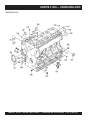
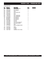
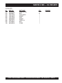
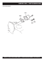
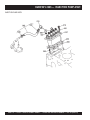
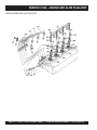
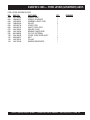
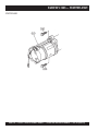
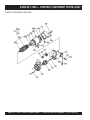
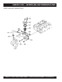
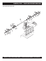
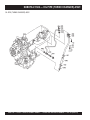
HTH44T— ENGINE (KUBOTA)
ENGINE (KUBOTA
PAGE 38 — HTH44T • RIDE-ON POWER TROWEL — OPERATION AND PARTS MANUAL — REV. #8 (03/27/12)
)
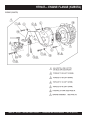
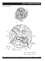
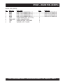
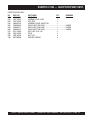
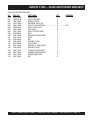
HTH44T— ENGINE (KUBOTA)
ENGINE (KUBOTA)
NO.
1
2
4
5
PART NO.
5218
5054A
4014
11517
6
7
8
9
10
11
12
13
14
15
16
17
18
19
20
21
22
23
24
25
26
27
28
29%
30
31
32
33
35
36
37
38
39
40
41
20295
10434
20123
20091
2198
0948
60049
20093
20108
12958
6869
0166A
11577
20112
8125
2955
0202
11662
10136
0300B
5283
8128
20122
17351-11083
16271-32090
16241-72870
36200-82720
20320
15263-12370
16282-97010
16285-52032
16241-64010
37560-63010
01123-50830
1629611013
PART NAME
QTY.
REMARKS
SCREW, HHC 1/2- 13 X 1- 1/2
6
WASHER, LOCK, 1/2 MED
6
SCREW, DRIVE #2- 3/16 U- DRIVE
2
MOUNT, RIGHT MOTOR ...................................... 1 ............... (REPLACE S/N TAG ONTO
................................................................................................. NEW MOUNT)
MUFFLER, HTH44
1
CLAMP, HOSE 2 INCH ID
2
HOSE, AIR CLEANER
1
PLATE, AIR DAM TOP
1
SCREW, SHC M6- 1.0 X 10MM
3
WASHER, FLAT 1/4 SAE
3
TRIM EDGE, 1/32 (62B3- 1/32) ............................ 1 ............... SOLD IN FOOT-LENGTHS
PLATE, AIR DAM REAR
1
ENGINE PACKAGE KUBOTA 44HP TURBO
1
MOUNT, ENGINE LEFT W/ A
2
SCREW, HHC 3/8- 24 X 1/2
8
WASHER, LOCK 3/8 MED.
8
PLATE, VIBRATION MOUNT
4
BRACKET, THROTTLE
1
CLAMP, HOSE SUPPORT, 5/8
1
WASHER,LOCK, 7/16 MED
4
SCREW, HHC 5/16- 18 X 1
1
SCREW, HHC M10- 1.25 X 25MM
5
WASHER, FLAT 3/8 SAE
1
WASHER, FLAT 5/16 SAE
1
NUT, NYLOC 5/16-18
1
CLAMP, HOSE SUPPORT 5/16
1
BLANKET, MUFFLER
1
ELEMENT, AIR CLEANER
1
OIL FILTER, ENGINE
1
HOSE, RADIATOR
2
CLAMP, RADIATOR
4
RADIATOR KIT
1
GASKET, MUFFLER
1
FAN BELT
1
FUEL PUMP, KUBOTA
1
ALTERNATOR
1
STARTER
1
BOLT, STARTER
2
AIR CLEANER ASSY ........................................... 1 ............... INCLUDES ITEMS W/%
HTH44T • RIDE-ON POWER TROWEL — OPERATION & PARTS MANUAL — REV. #8 (03/27/12) — PAGE 39
— PAGE RM
HTH44T— ENGINE FLANGE (KUBOTA)
ENGINE (KUBOTA)
PAGE 40 — HTH44T • RIDE-ON POWER TROWEL — OPERATION AND PARTS MANUAL — REV. #8 (03/27/12)
)
HTH44T— ENGINE FLANGE (KUBOTA)
ENGINE (KUBOTA)
NO.
1
2
3
4
7
8
9
10
11
12
13
15
16
17
18
19
PART NO.
5218
5054A
N/A
N/A
11605
N/A
11531
N/A
N/A
N/A
11378
10136
0166A
1284
11517
N/A
PART NAME
QTY.
REMARKS
SCREW, HHC 1/2- 13 X 1- 1/2
2
WASHER, LOCK, 1/2 MED
2
SCREW, HHC M10 -1.25 X 35MM GRD10.9 ........ 2 ............... SOURCE LOCALLY
WASHER, FLAT 10MM ......................................... 2 ............... SOURCE LOCALLY
FLANGE, NYLON
1
SCREW, SHC M10 -1.25 X 30MM GRD12.9 ........ 3 ............... SOURCE LOCALLY
BELL HOUSING, KTR
1
WASHER, FLAT 8MM ........................................... 4 ...............SOURCE LOCALLY
SCREW, SHC M8 -1.25 X 30MM GRD12.9 .......... 4 ............... SOURCE LOCALLY
SCREW, SHC M10-1.5 X 30MM GRD12.9 ........... 1 ............... SOURCE LOCALLY
HUB, HYDRAULIC PUMP
1
WASHER, FLAT 3/8 SAE
2
WASHER, LOCK 3/8 MED
2
SCREW, HHC 3/8-16 X 1- 1/2
2
MOUNT, RIGHT MOTOR
1
NUT, HEX, M8 - 1.25 ............................................ 1 ............... SOURCE LOCALLY
HTH44T • RIDE-ON POWER TROWEL — OPERATION & PARTS MANUAL — REV. #8 (03/27/12) — PAGE 41
— PAGE RM
HTH44T— ENGINE FUEL (KUBOTA)
ENGINE FUEL(KUBOTA)
PAGE 42 — HTH44T • RIDE-ON POWER TROWEL — OPERATION AND PARTS MANUAL — REV. #8 (03/27/12)
)
HTH44T— ENGINE FUEL (KUBOTA)
ENGINE FUEL(KUBOTA)
NO.
1
2
3
4
5
6
7
8
PART NO.
60028
60004
60028
60028
19473
70000-43081
11662
2955
PART NAME
QTY.
REMARKS
HOSE, .312 ID RUBBER FUEL 14" ..................... 1 ............... SOLD IN FOOT-LENGTHS
HOSE, .187 ID RUBBER FUEL 30" ..................... 1 ............... SOLD IN FOOT-LENGTHS
HOSE, .312 ID RUBBER FUEL 17" ..................... 1 ............... SOLD IN FOOT-LENGTHS
HOSE, .312 ID RUBBER FUEL 25" ..................... 1 ............... SOLD IN FOOT-LENGTHS
CLAMP, WORM HOSE, #4 (1/4- 5/8)
6
FILTER, CANNISTER FUEL
1
SCREW, HHC M10- 1.25 X 25MM
2
WASHER, LOCK, 7/16 MED
2
HTH44T • RIDE-ON POWER TROWEL — OPERATION & PARTS MANUAL — REV. #8 (03/27/12) — PAGE 43
— PAGE RM
HTH44T— HYDRAULIC STEERING (LEFT)
HYDRAULIC STEERING (LEFT)
PAGE 44 — HTH44T • RIDE-ON POWER TROWEL — OPERATION AND PARTS MANUAL — REV. #8 (03/27/12)
)
HTH44T— HYDRAULIC STEERING (LEFT)
HYDRAULIC STEERING (LEFT)
1
2
3*
4*
5*#
6*#
7*
8
9
10
11
12
20095
20096
11142
11146
12038
12060
12056
11141
12318
10176
11725
12156
13*#
14*#
15*#
16
10229
0161C
0300B
11696
TUBE, HYD. STEERING PRESSURE
1
TUBE, HYD. STEERING RETURN
1
ROD END, 1/2- 20 MALE RH
2
NUT, HEX JAM 1/2- 20
2
BELLOWS, STG. CYLINDER
1
PLATE, BELLOWS MOUNTING
1
CYLINDER, STEERING ....................................... 1 ............... INCL ITEMS W/ #
SPACER, ROD END
4
SCREW, HHC 1/2- 13 X 2 3/4
2
NUT, NYLOC 1/2- 13
2
FITTING, STEERING 6MJ- 1/4MP
2
CYLINDER ASM, STEERING ............................... 1 ............... INCLUDES ITEMS W/ * AND
.................................................................................................
INSTRUCTION SHEET
SCREW, HHC 5/16- 20 X 1
4
WASHER, LOCK 5/16 MED
4
WASHER, FLAT 5/16 SAE
4
HOSE ASM, .38 ID X 35.5 STR.ENDS
2
HTH44T • RIDE-ON POWER TROWEL — OPERATION & PARTS MANUAL — REV. #8 (03/27/12) — PAGE 45
— PAGE RM
HTH44T— HYDRAULIC STEERING (RIGHT)
HYDRAULIC STEERING (RIGHT)
PAGE 46 — HTH44T • RIDE-ON POWER TROWEL — OPERATION AND PARTS MANUAL — REV. #8 (03/27/12)
)
HTH44T— HYDRAULIC STEERING (RIGHT)
HYDRAULIC STEERING (RIGHT)
1
2
3
4
5
7
8
9
11*
12*#
13*#
14*#
15*#
16*#
17
18
19
20*
21*
22
23
24
25
20095
20084
12213
11949
12055
20085
20096
12079
12056
12038
12060
0300B
0161C
10229
12318
11141
10176
11142
11146
13178
11725
12409
12156
26
27
28
29
30
31
32
20143
11698
16334
16333
12275
12274
12273
TUBE, HYD. STEERING PRESSURE
1
TUBE, HYD. STRG. CYC. ROD END HTH- T
1
HOSE ASM, .38 ID X 24 90 ONE END
1
HOSE ASM, 3/8 ID X 23 06 STR. ENDS
1
HOSE ASM, .38 ID X 36 45 ONE END
2
TUBE, HYD. STRG. CYL. BASE END HTH- T 1
TUBE, HYD. STEERING RETURN
1
HOSE ASM, .38 ID X 17 STR ENDS
2
CYLINDER, STEERING ....................................... 2 ............... INCL ITEMS W/ #
BELLOWS, STG. CYLINDER
2
PLATE, BELLOWS MOUNTING
2
WASHER, FLAT 5/16 SAE
8
WASHER, LOCK 5/16 MED
8
SCREW, HHC 5/16- 20 X 1
8
SCREW, HHC 1/2- 13 X 2 3/4
3
SPACER, ROD END
8
NUT, NYLOC 1/2- 13
4
ROD END, 1/2- 20 MALE RH
4
NUT, HEX JAM 1/2- 20
4
SCREW, HHC 1/2- 13 X 2 1/4
1
FITTING, STEERING 6MJ- 1/4MP
4
FITTING, 45 6MJ- 6MO
1
CYLINDER ASM, STEERING ............................... 1 ............... INCLUDES ITEMS W/ * AND
.................................................................................................
INSTRUCTION SHEET
VALVE ASM, STEERING REGULATOR
1
HOSE ASM, .38 ID X 15.5 STR. ENDS
1
NUT, HEX JAM BLKHD .5625-18UNF
2
FITTING, STR 6MJ BLKHD UNION
2
SCREW, CLAMP STAUFF ASDS1
1
COVER, CLAMP STAUFF USDS1
1
CLAMP, 3/8 TUBE PLASTIC PAIR
1
HTH44T • RIDE-ON POWER TROWEL — OPERATION & PARTS MANUAL — REV. #8 (03/27/12) — PAGE 47
— PAGE RM
HTH44T— STEERING VALVE ASSY. (LEFT)
STEERING VALVE ASSEMBLY (LEFT)
PAGE 48 — HTH44T • RIDE-ON POWER TROWEL — OPERATION AND PARTS MANUAL — REV. #8 (03/27/12)
)
HTH44T— STEERING VALVE ASSY. (LEFT)
STEERING VALVE ASSEMBLY (LEFT)
NO.
1*
2*
3*
6*
7*
8*
9*
10*
11*
12*
13*
14
15*
16
17
18
19
20
21*
22*
23*
24*
PART NO.
HU51494
HU51941
HU51770
12519
HU51774
HU51773-1
HU51775
12536
HU51761
HU53748
12523
11423
12521
11722
11721
12147
12148
11723
HU3182
HU53-906
HU3108
HU53-908
PART NAME
QTY.
REMARKS
NUT, SPECIAL
1
PLATE, PIVOT
1
RETAINING RING, - EXT
3
BOOT, LEFT
1
PIVOT PIN
1
CLAMP, BOOT
1
SCREW, CAP, FLAT HD
1
GASKET
2
SCREW, CAP, FLAT HD
1
SPRING
2
PLUNGER CAPSULE ASM
2
VALVE ASM, HTH44T STRG LEFT ...................... 1 ............... INCLUDES ITEMS WITH *
METERING CAPSULE ASM
2
FITTING, 90 6MJ-6MO
1
FITTING, STR 6MJ-6MO
2
FITTING, QC DIAGN PARKER PD-361
1
CAP, DUST DIAG PARKER PD6-285
1
FITTING, 90 6MJ-8MO
1
PLUG, SAE
1
O-RING
1
PLUG, SAE
1
O-RING
1
HTH44T • RIDE-ON POWER TROWEL — OPERATION & PARTS MANUAL — REV. #8 (03/27/12) — PAGE 49
— PAGE RM
STEERING VALVE ASSEMBLY (RIGHT)
PAGE 50 — HTH44T • RIDE-ON POWER TROWEL — OPERATION AND PARTS MANUAL — REV. #8 (03/27/12)
)
HTH44T— STEERING VALVE ASSY. (RIGHT)
STEERING VALVE ASSEMBLY (RIGHT)
NO.
1*
2*
4*
7*
8*
9*
10*
11*
12
13*
14
15
16
PART NO.
HU51494
12518
HU515026
12790
12524
11146
HU53748
12523
11422
12521
11780
12159
11721
PART NAME
QTY.
REMARKS
NUT, SPECIAL
1
BOOT, RIGHT
1
PLATE, PIVOT
1
RETAINER, STRG VALVE BOOT
1
GASKET
4
NUT, HEX JAM 1/2- 20
1
SPRING
6
PLUNGER CAPSULE ASM
6
VALVE ASM, HTH44T STRG RIGHT ................... 1 ............... INCLUDES ITEMS WITH *
METERING CAPSULE ASM
6
FITTING, 45 6MJ-6MO
1
FITTING, TEE 6MJ-6MO-6MJ
2
FITTING, STR 6MJ-6MO
3
HTH44T • RIDE-ON POWER TROWEL — OPERATION & PARTS MANUAL — REV. #8 (03/27/12) — PAGE 51
— PAGE RM
HTH44T— PALM HANDLES (LEFT AND RIGHT)
PALM HANDLES (LEFT AND RIGHT)
PAGE 52 — HTH44T • RIDE-ON POWER TROWEL — OPERATION AND PARTS MANUAL — REV. #8 (03/27/12)
)
HTH44T— PALM HANDLES (LEFT AND RIGHT)
PALM HANDLES (LEFT AND RIGHT)
NO.
1
2
3
4
5
6
7
10
11
12
PART NO.
22001
22003
11146
11423
22002
22004
11422
20314
1318
4692
PART NAME
HANDLE, PALM W/ SWITCH, LEFT
TUBE, HANDLE SWITCH
NUT, HEX JAM 1/2 - 20
VALVE ASM, STEERING (LEFT)
HANDLE, PALM W/O SWITCH, RIGHT
TUBE, HANDLE SOLID
VALVE ASM, STEERING (RIGHT)
SWITCH ASM
TERMINAL, BULLET, FEMALE 18-22
TERMINAL, BULLET, MALE 14-16
QTY.
1
1
2
1
1
1
1
1
1
1
REMARKS
HTH44T • RIDE-ON POWER TROWEL — OPERATION & PARTS MANUAL — REV. #8 (03/27/12) — PAGE 53
— PAGE RM
HTH44T— HYDRAULIC DRIVE ASSEMBLY
HYDRAULIC DRIVE ASSEMBLY
PAGE 54 — HTH44T • RIDE-ON POWER TROWEL — OPERATION AND PARTS MANUAL — REV. #8 (03/27/12)
)
HTH44T— HYDRAULIC DRIVE ASSEMBLY
HYDRAULIC DRIVE ASSEMBLY
NO.
1
2
3
4
5
6
7
8
9
10
11
13
14
15
16
17
18
19
21
PART NO.
11723
11892
12804
12433
12147
12148
11590
11386
11721
11698
20191
20190
11588
8125
0300B
5283
11699
11591
11589
PART NAME
QTY.
FITTING, 90 6MJ- 6MO
1
FITTING, 90 IMP- 3/4FP SWIVEL
1
PUMP ASM,TANDEM HTH
1
FITING,TEE 12MJ- 12MO- 6FO
2
FITTING, QC DIAGN PARKER PD- 361
2
CAP, DUST DIAG PARKER PD6- 285
2
HOSE ASM, .75ID X 24 90 DEG. ENDS
1
FITTING, STR. 12MJ- 12MO
6
FITTING, STR. 6MJ- 6MO
3
HOSE ASM, .38ID X 15.5 STR. ENDS
1
HOSE ASM, .51ID X 14LG 90 DEG. ONE END 1
FITTING, CROSS 6MJ- 8MJ- 6MJ- 8MJ
1
HOSE ASM, .75ID X 27 90 DEG. ONE END
1
CLAMP, HOSE SUPPORT 5/8
1
WASHER, FLAT 5/16 SAE
1
NUT, NYLOC 5/16- 18
1
HOSE ASM, .38ID X 52.5 STR. ENDS
1
HOSE ASM, .75ID X 41 90 DEG. ENDS
1
HOSE ASM, .75ID X 50 90 DEG. ONE END
1
REMARKS
HTH44T • RIDE-ON POWER TROWEL — OPERATION & PARTS MANUAL — REV. #8 (03/27/12) — PAGE 55
— PAGE RM
HTH44T— HYDRAULIC DRIVE PUMP LEVER ASSY.
HYDRAULIC DRIVE PUMP LEVER ASSEMBLY
1
2
3
4
5
14
6
1
9
10
8
7
3
12
4
5
11
13
12
1
SPEED CONTROL CABLE ASSY,
SEE PAGE 78.
PAGE 56 — HTH44T • RIDE-ON POWER TROWEL — OPERATION AND PARTS MANUAL — REV. #8 (03/27/12)
)
HTH44T— HYDRAULIC DRIVE PUMP LEVER ASSY.
HYDRAULIC DRIVE PUMP LEVER ASSEMBLY
NO.
1
2
3
4
5
6
7
8
9
10
11
12
13
14
PART NO.
0424
12357
11875
11874
10024
11613
11610
6904
0948
20003
12356
12580
26250
21449
PART NAME
QTY.
REMARKS
SCREW, HHC 1/4- 20 X 1 1/4
1
CLEVIS, PUMP ACTUATOR, LEFT HAND
1
SPACER, PUMP LEVER GROMMET
2
GROMMET, LEVERMINOR #Z- 2064
2
NUT, NYLOC 1/4- 20
2
NUT, HEX FULL 1/4- 28 LEFT HAND
1
ROD, PUMP ACTUATOR
1
NUT, HEX FINISH 1/4- 28
1
WASHER, FLAT 1/4 SAE
1
ROD END, 1/4 - 28 FEM RH W/ZERK
1
CLEVIS, PUMP ACTUATOR, RT. HAND
1
LEVER, PUMP TL SPEN SP791- 11
2
SCREW, HHC 1/4- 20 X 1- 3/4
1
KIT, PUMP LEVER CLEVIS ................................. 1 ............... REPLACES 12593
HTH44T • RIDE-ON POWER TROWEL — OPERATION & PARTS MANUAL — REV. #8 (03/27/12) — PAGE 57
— PAGE RM
HTH44T— HYDRAULIC DRIVE FILTERS AND COOLING
HYDRAULIC DRIVE FILTERS AND COOLING
PAGE 58 — HTH44T • RIDE-ON POWER TROWEL — OPERATION AND PARTS MANUAL — REV. #8 (03/27/12)
)
HTH44T— HYDRAULIC DRIVE FILTERS AND COOLING
HYDRAULIC DRIVE FILTERS AND COOLING
NO.
1
2
3
4
5
6
7
8
10
11
12
13
14
15
16
17
18
19
20
21
22
23
PART NO.
12575
3333
20251
12537
11580
12114
11579
11297
11783
0300B
5283
20237
20238
20567
11883
11893
11892
3367
3462
11870
11396
11402
24
25
26
27
28
11754
11749
12176
12179
12171
PART NAME
QTY.
REMARKS
FITTING, 45 8 BARB X 3/8 MP
1
CLAMP, 1.1/4 HOSE
4
HOSE, .5ID 100R3 21 LONG
1
FITTING, 45 8BARB X 1/2 MP
1
FAN, COOLING BLADE
2
SHROUD, OIL COOLING FAN
1
MOTOR, 12 VOLT FAN
2
COOLER, OIL
1
BOLT, CARRIAGE 5/16- 18 X 3
4
WASHER, FLAT 5/16 SAE
4
NUT, NYLOC 5/16- 18
4
FITTING,TEE 08MJ X 08MJ X .5MP
1
HOSE ASM, .51ID X 16.5 STR. ENDS
1
ELEMENT, FILTER SUC. STAUFF SF6710
1
HOUSING, FILTER SUC. ZINGA SF- 100
1
FITTING, NIPPLE IMP CLOSE
1
FITTING, 90 IMP- 3/4FP SWIVEL
1
FITTING, 12 BARB- 3/4MP
1
HOSE ASM, .75ID 100R4 16.5 LONG
1
FITTING, 90 12 BARB- 8MO ................................ 1 ...............CHARGE PUMP INLET
FITTING, 8MJ X 8MO
1
FILTER .................................................................. 1 ............... STAUFF SF-6520, ZINGA AE-10
................................................................................................. OR EQUIVALENT
HOUSING, FILTER
1
FITTING, STR. 8MJ- 8MO
1
CONNECTOR, WEATHERPACK 2 PIN
1
TERMINAL, W'PACK MALE 14-16 GA
2
SEAL, WEATHERPACK 16-18 GA
2
HTH44T • RIDE-ON POWER TROWEL — OPERATION & PARTS MANUAL — REV. #8 (03/27/12) — PAGE 59
— PAGE RM
HTH44T— FIVE BLADE SPIDER ASSY. (LEFT)
FIVE BLADE SPIDER ASSEMBLY (LEFT SIDE)
PAGE 60 — HTH44T • RIDE-ON POWER TROWEL — OPERATION AND PARTS MANUAL — REV. #8 (03/27/12)
)
HTH44T— FIVE BLADE SPIDER ASSY. (LEFT)
FIVE BLADE SPIDER ASSEMBLY (LEFT SIDE)
NO.
1
2
PART NO.
11419
20426
3
4
5
6
7
8
9
10
11
12
13
14
15
16
17
18
19
20
21
22
23
24
25
26
27
1162A
2621
11431
12779
20180
2829
9005
9006
0166A
1876
0164B
9111
11039
1875
1162A
1322
2218
20041
20073
4388
20121
20179
0105
0161C
0121A
PART NAME
QTY.
REMARKS
PLATE, WEAR
1
BUSHING, THRUST MACHINED ......................... 1 ............... ORIENT HOLE WITH GREASE
................................................................................................. HOLE IN THRUST COLLAR
CAP, GREASE ZERK #2
1
ZERK, GREASE STR 1/4- 28
1
THRUST COLLAR W/ BUSHING
1
BEARING,THRUST 6017 2RS W/FLANGE
1
SPIDER ASM,LEFT SIDE
1
ARM, TROWEL, HD EXTENDED
5
LEVER, TROWEL ARM LEFT SIDE
5
PIN, ROLL 5/16 X 2
5
WASHER, LOCK, 3/8 MED
5
NUT, HEX JAM 3/8 X 16 CLASS 2B
5
SCREW, TROWEL ADJUSTMENT
5
SPRING, LS ARM RETURN HD/HT, SM BOSS 5
BUSHING, ARM 2 PIECE
10
WASHER, INT. SHKP. 3/8
5
CAP, GREASE ZERK #2
5
SCREW ASM, ARM RETAINING
5
CAP PLUG ............................................................ 5 ............... REPLACES P/N 11602
SPIDER, HTH TAPER 5 BL
1
RETAINER, SPIDER
1
WASHER,LOCK 3/4 MED
1
PLUG, SPIDER SNAP IN
1
SCREW, HHC 3/4- 16 X 2, GR8
1
SCREW, HHC 5/16 -18 X 1 1/2
15
WASHER, LOCK 5/16
15
FITTING, PLUG 3/8MP SQ HEAD
1
HTH44T • RIDE-ON POWER TROWEL — OPERATION & PARTS MANUAL — REV. #8 (03/27/12) — PAGE 61
— PAGE RM
HTH44T— FIVE BLADE SPIDER ASSY. (RIGHT)
FIVE BLADE SPIDER ASSEMBLY (RIGHT SIDE)
PAGE 62 — HTH44T • RIDE-ON POWER TROWEL — OPERATION AND PARTS MANUAL — REV. #8 (03/27/12)
)
HTH44T— FIVE BLADE SPIDER ASSY. (RIGHT)
FIVE BLADE SPIDER ASSEMBLY (RIGHT SIDE)
NO.
1
2
PART NO.
11419
11464
3
4
5
6
7
8
9
10
11
12
13
14
15
16
17
18
19
20
21
22
23
24
25
26
27
1162A
2621
11431
12779
20181
2829
1986
9006
0166A
1876
0164B
2143
11039
1875
1162A
1322
2218
20041
20073
4388
20121
20179
0105
0161C
0121A
PART NAME
QTY.
REMARKS
PLATE, WEAR
1
BUSHING, THRUST MACHINED ......................... 1 ............... ORIENT HOLE WITH GREASE
................................................................................................. HOLE IN THRUST COLLAR
CAP, GREASE ZERK #2
1
ZERK, GREASE STR 1/4- 28
1
THRUST COLLAR, W/ BUSHING
1
BEARING, THRUST 6017 2RS W/FLANGE
1
SPIDER ASM, RIGHT SIDE
1
ARM, TROWEL, HD EXTENDED
5
LEVER, TROWEL ARM RIGHT SIDE
5
PIN, ROLL 5/16 X 2
5
WASHER, LOCK, 3/8 MED
5
NUT, HEX JAM 3/8 X 16 CLASS 2B
5
SCREW, TROWEL ADJUSTMENT
5
SPRING, RIGHT TROWEL
5
BUSHING, ARM 2 PIECE
10
WASHER, INT. SHKP. 3/8
5
CAP, GREASE ZERK #2
5
SCREW ASM, ARM RETAINING
5
CAP PLUG ............................................................ 5 ............... REPLACES P/N 11602
SPIDER, HTH TAPER 5 BL
1
RETAINER, SPIDER
1
WASHER, LOCK 3/4 MED
1
PLUG, SPIDER, SNAP IN
1
SCREW,HHC 3/4- 16 X 2, GR8
1
SCREW, HHC 5/16 -18 X 1 1/2
15
WASHER, LOCK 5/16
15
FITTING, PLUG 3/8MP SQ HEAD
1
HTH44T • RIDE-ON POWER TROWEL — OPERATION & PARTS MANUAL — REV. #8 (03/27/12) — PAGE 63
— PAGE RM
HTH44T— STABILIZER RING ASSY.
STABILIZER ASSEMBLY
PAGE 64 — HTH44T • RIDE-ON POWER TROWEL — OPERATION AND PARTS MANUAL — REV. #8 (03/27/12)
)
HTH44T— STABILIZER RING ASSY.
STABILIZER ASSEMBLY
NO.
1
2
3
4
5
PART NO.
12095
6014C
0161C
1723
1237
PART NAME
RING, STABILIZER, EXT ARM, HD
NUT, HEX FINISH 5/16-24
WASHER, LOCK, 5/16 MED
ROD END, 5/16-24 MALE
SCREW, SCH 5/16-18 X 7/8
QTY.
1
10
10
5
5
REMARKS
HTH44T • RIDE-ON POWER TROWEL — OPERATION & PARTS MANUAL — REV. #8 (03/27/12) — PAGE 65
— PAGE RM
HTH44T— LOCATOR DECALS
LOCATOR DECALS
PAGE 66 — HTH44T • RIDE-ON POWER TROWEL — OPERATION AND PARTS MANUAL — REV. #8 (03/27/12)
)
HTH44T— LOCATOR DECALS
LOCATOR DECALS
NO.
1
2
3
4
5
6
7
8
9
10
11
12
13
14
15
16
17
18
19
20
PART NO.
11246
11712
20486
11711
11247
20196
20207
11811
20209
2814
20200
13118
10818
10024
12288
12401
1499
2300
2332
2634
PART NAME
QTY.
REMARKS
DECAL, INTL STDS, ISO ..................................... 1 ............... SEE DECAL SHEET PAGE 66
DECAL, ENGINE SPEED
1
DECAL, HYD RIDER COLD START
1
DECAL, INSTRUMENT LIGHT
1
DECAL, SAFETY CLOTHING, ISO
1
DECAL, "MQ" 6.22 X 5.00
1
DECAL, “TURBOCHARGED” 0.80 X 9.00
1
DECAL, DIESEL FUEL
1
DECAL, “HYDROSTATIC” 16.00 X 1.73
1
DECAL, KEY SWITCH LIGHTS
1
DECAL, “HTH SERIES” 5.00 X 3.30
1
DECAL, POWDER COATED
1
DECAL, “MQ WHITEMAN” 24 X 3
1
NUT, NYLOC 1/4- 20
2
SCREW, THP 1/4- 20 X 1 SS
2
DECAL, PRESSURIZED TANK CAUTION
1
DECAL, "MQ WHITEMAN"
2
DECAL, AL PITCH RH
1
DECAL, AL PITCH LH
1
DECAL, SPRING SAFETY
2
HTH44T • RIDE-ON POWER TROWEL — OPERATION & PARTS MANUAL — REV. #8 (03/27/12) — PAGE 67
— PAGE RM
HTH44T— TOP PANEL (LEFT) ASSY.
TOP PANEL (LEFT)
PAGE 68 — HTH44T • RIDE-ON POWER TROWEL — OPERATION AND PARTS MANUAL — REV. #8 (03/27/12)
)
HTH44T— TOP PANEL (LEFT) ASSY.
TOP PANEL (LEFT)
NO.
1
2
3
4
5
6
7
8
9
10
11
12
PART NO.
20022
20047
20032
20063
20104
60049
12287
11534
12288
10024
0948
11983
PART NAME
QTY.
REMARKS
PANEL, LEFT FRONT
1
PANEL, LEFT BACK
1
SEAT FRAME
1
PANEL, SEAT FRAME TOP LEFT
1
COVER, OIL COOLER
1
TRIM EDGE, 1/32 (62B3- 1732)
4
SCREW, THP1/4- 20 X 3/4 SS
12
NUT, U- TYPE 1/4- 20
12
SCREW, THP 1/4- 20 X 1 SS
6
NUT, NYLOC 1/4- 20
5
WASHER, FLAT 1/4 SAE
5
TANK, OVERFLOW (RADIATOR) ........................ 1 ............... INCLUDES BOTTLE, BRACKET
................................................................................................. AND HOSES
HTH44T • RIDE-ON POWER TROWEL — OPERATION & PARTS MANUAL — REV. #8 (03/27/12) — PAGE 69
— PAGE RM
HTH44T— TOP PANEL (RIGHT) ASSY.
TOP PANEL (RIGHT)
PAGE 70 — HTH44T • RIDE-ON POWER TROWEL — OPERATION AND PARTS MANUAL — REV. #8 (03/27/12)
)
HTH44T— TOP PANEL (RIGHT) ASSY.
TOP PANEL (RIGHT)
NO.
1
2
3
5
6
7
8
9
10
11
12
13
14
15
18
19
20
21
22
23
24
26
27
28
PART NO.
12287
12288
0948
0181B
11694
3513
2153
0937
10568
10019
10024
11379
29057
20021
11534
0169
4001
11593
11265
10133
12005
11382
12307
11585
PART NAME
SCREW, THP1/4- 20 X 3/4 SS
SCREW, THP 1/4- 20 X 1 SS
WASHER, FLAT 1/4 SAE
WASHER, LOCK 1/4 MED
HOUR METER
SCREW, HHC 10- 32 X 1
ROD END,10- 32 FEMALE RH.
NUT, HEX #10- 32
CABLE, THROTTLE, HONDA RIDER
NUT, NYLOC 10- 32
NUT, NYLOC 1/4- 20
LEVER, ENGINE SPEED CONTROL
DOCUMENT BOX, (CP90007- 07)
PANEL, RIGHT BACK
NUT, U- TYPE 1/4- 20
SCREW, HHC 3/8- 16 X 3.0 LG
WASHER, FLAT 3/8 USS PLD
SPRING, SEAT (CENTURY #10321)
WASHER, STEERING HANDLE
NUT, NYLOC 3/8- 16
SWITCH, KILL COLE-HER #90036-2
PLUG, OIL, WATER, CHARGE (RED)
BULB, INDICATOR LIGHT
PLUG, PREHEAT LIGHT (BLUE)
QTY.
16
6
6
1
1
1
1
1
1
2
6
1
1
1
8
1
1
1
2
1
1
1
1
1
REMARKS
HTH44T • RIDE-ON POWER TROWEL — OPERATION & PARTS MANUAL — REV. #8 (03/27/12) — PAGE 71
— PAGE RM
HTH44T— FRONT PANEL (RIGHT) ASSY.
FRONT PANEL (RIGHT)
PAGE 72 — HTH44T • RIDE-ON POWER TROWEL — OPERATION AND PARTS MANUAL — REV. #8 (03/27/12)
)
HTH44T— FRONT PANEL (RIGHT) ASSY.
FRONT PANEL (RIGHT)
NO.
1
2
3
4
5
6
7
8
9
9A
10
11
12
13
PART NO.
20034
12287
0948
5065B
2203
8381
10568
4682
20511
12627
10019
11098
10024
11792
PART NAME
PANEL, RIGHT FRONT
SCREW,THP 1/4- 20 X 3/4 SS
WASHER, FLAT 1/4 SAE
SCREW, RHM 10- 32 X 1/2
WASHER, FLAT #10 SAE
BOOT, TOGGLE SWITCH
CABLE, THROTTLE, HONDA RIDER
SWITCH, TOGGLE ELEC. #9061
SWITCH, IGNITION (W/KEYS)
UNIVERSAL KEY SET
NUT, NYLOC 10 - 32
CIRCUIT BRKR.WAYTEK #46540 40 AMP
NUT, NYLOC 1/4- 20
ACCESSORY SOLENOID
QTY.
1
2
2
2
2
1
1
1
1
1
2
1
2
1
REMARKS
HTH44T • RIDE-ON POWER TROWEL — OPERATION & PARTS MANUAL — REV. #8 (03/27/12) — PAGE 73
— PAGE RM
HTH44T— SEAT AND FRAME ASSY.
SEAT AND FRAME
PAGE 74 — HTH44T • RIDE-ON POWER TROWEL — OPERATION AND PARTS MANUAL — REV. #8 (03/27/12)
)
HTH44T— SEAT AND FRAME ASSY.
SEAT AND FRAME
NO.
1
2
3
4
5
6
7
8
9
10
11
12
PART NO.
20032
11632
20059
0300B
5283
10306
8087
10176
8081
0183
20061
12287
PART NAME
FRAME, SEAT
SEAT W/ ARM REST
PLATE, SEAT HTH- 44T
WASHER, FLAT 5/16 SAE
NUT, NYLOC 5/16- 18
SCREW, HHC 1/2- 13 X 4 1/2
SCREW, HHC 1/2- 13 X 4
NUT, NYLOC 1/2- 13
PIN, CLEVIS 1/2 X 2.75 EFF.
PIN, COTTER 1/8 1- 1/4
PANEL, FRONT CENTER SEAT FRAME
SCREW, THP1/4- 20 X 3/4 SS
QTY.
1
1
1
4
4
4
4
8
2
2
1
4
REMARKS
HTH44T • RIDE-ON POWER TROWEL — OPERATION & PARTS MANUAL — REV. #8 (03/27/12) — PAGE 75
— PAGE RM
HTH44T— FRAME AND FUEL TANK ASSY.
FRAME AND FUEL TANK ASSY.
A
1
3
1
3
2
22
23
21
2
24
20
19
25
9
P
18
O
W
DER
C O AT
E
D
11
4
17
CONNECT TO FUEL PUMP
SEE PAGE 42.
5
6
12
15
14
FUEL RETURN LINE
FROM ENGINE SEE PAGE 42.
8
13
7
12
STUD BOLT FOR FUEL TANK
BRACKET IS WELDED TO FRAME
9
10
8
1
FOR COMPLETE PEDAL PARTS
BREAKDOWN SEE DETAIL A,
PAGE 78.
2
SPRAY ASSEMBLY,
SEE PAGE 82.
9
PAGE 76 — HTH44T • RIDE-ON POWER TROWEL — OPERATION AND PARTS MANUAL — REV. #8 (03/27/12)
)
HTH44T— FRAME AND FUEL TANK ASSY.
FRAME AND FUEL TANK ASSY.
NO.
1
2
3
4
5
6
7
8
9
10
11
12
13
14
15
17
18
19
20
21
22
23
24
25
PART NO.
11628
0202
0105
11678
11418
12025
11922
0300B
5283
12021
20160
19633
12006
12010
60058
12023
11584
12489
ZINFB04
ZINPS0014
12332
ZINFB15
ZINFB08
3233
PART NAME
FOOT REST, LEFT
SCREW, HHC 5/16- 18 X 1
SCREW, HHC 5/16- 18 X 1 1/2
PANEL, FRONT HTH/STH
FUEL CAP/ GAUGE (10.5)
SPACER, FUEL TANK
TANK, 12 GALLON FUEL POLYETHYLENE
WASHER, FLAT 5/16 SAE
NUT, NYLOC 5/16- 18
BRACKET, FUEL TANK SUPPORT
FRAME
BUSHING, RUBBER FUEL
FITTING, 90 03BARB- 4BARB FUEL
SCREEN, FUEL (DAPCO 11656)
HOSE, FUEL YELLOW 1/4 X 3/8 X 2"
FITTING, 90 05BARB- 4BARB FUEL
SIGHT GLASS, 3/4 MALE PIPE
FLANGE GASKET
BASE
SCREW, #10 - 32 1/2
CAP, HYD 5PSI 10 MICRON
JACK CHAIN, #16 SINGLE
CHAIN RING
WASHER, FENDER 1.50D X 3/8 ID
QTY.
1
2
2
1
1
2
1
4
6
2
1
2
1
1
1
1
1
1
1
6
1
1
1
2
REMARKS
HTH44T • RIDE-ON POWER TROWEL — OPERATION & PARTS MANUAL — REV. #8 (03/27/12) — PAGE 77
— PAGE RM
HTH44T— FOOT PEDALS ASSY.
FOOT PEDALS ASSY.
PAGE 78 — HTH44T • RIDE-ON POWER TROWEL — OPERATION AND PARTS MANUAL — REV. #8 (03/27/12)
)
HTH44T— FOOT PEDALS ASSY.
FOOT PEDALS ASSY.
NO.
1
2
3
4
5
6
7
8
9
10
11
12
13
14
15
16
17
18
19
PART NO.
11628
11491
11228
11199
10136
6014B
11677
1484
11656
11611
11643
19378
2755
11641
11638
11492
20003
10024
0730
PART NAME
FOOT REST, LEFT W/A
CABLE, THROTTLE ASM
ACCELERATOR PEDAL
BASE, SPEED CONTROL PEDAL
WASHER, FLAT 3/8 SAE
PIN, COTTER 3/32 X 1
PIN, SPEED CONTROL LEVER
BUSHING, BRONZE
ROCKER, SPEED CONTROL
ROD END, 1/4- 28 FEMALE RH
ROD END, 1/4- 28 MALE RH
NUT, HEX JAM 1/4- 28
ADAPTER, THROTTLE SPRING, SHORT
SPRING, THROTTLE RETURN
ADAPTER, SPEED CTRL SPRING
U- BOLT, CABLE
ROD END, 1/4- 28 FEMALE RH W/ZERK
NUT, NYLOC 1/4- 20
SCREW, HHC 1/4- 20 X 1
QTY.
1
1
1
1
5
4
2
2
1
2
1
3
1
1
1
1
1
3
3
REMARKS
HTH44T • RIDE-ON POWER TROWEL — OPERATION & PARTS MANUAL — REV. #8 (03/27/12) — PAGE 79
— PAGE RM
HTH44T— BATTERY ASSY.
PAGE 80 — HTH44T • RIDE-ON POWER TROWEL — OPERATION AND PARTS MANUAL — REV. #8 (03/27/12)
)
HTH44T— BATTERY ASSY.
BATTERY ASSY.
NO.
1
2
3
4
5
6
7
8
9
10
11
12
13
14
15
16
17
19
20
21
22
23
24
25
PART NO.
10314
1597
10313
1605
0161C
0479
2509
10031
11692
11693
10318
10315
0949
11362
0948
13212
0730
10930
11680
60052
10024
11534
0166A
11691
PART NAME
QTY.
REMARKS
BATTERY CABLE (RED)
1
CABLE ASM., BLK (NEG) 16.5
1
CABLE, NEG BATTERY BLACK 20
1
SCREW, HHC M8- 1.25 X 25MM
1
WASHER,LOCK, 5/16 MED.
1
WASHER, EXT SHKP 3/8 PLTD
1
WING NUT PLATED
2
WASHER, EXT SHKP 1/4
2
BRACKET, BATTERY BOX
1
BOLT, BATTERY BRKT
2
BATTERY BOX, GROUP 24
1
BATTERY 12V WET GROUP
1
NUT, HEX FINISH 1/4- 20
4
BATTERY BOX
1
WASHER, FLAT, 1/4 SAE
12
GROMMET, 1- 1/4 ID (MINOR #Z- 7141)
2
SCREW, HHC 1/4- 20 X 1
6
WASHER, FENDER 1/4 X 1 1/4
4
COVER, REAR MAIN FRAME
1
TRIM EDGE, 3/16 (100B3-3/16) ........................ 4.0 ............... SOLD IN FOOT-LENGTHS
NUT, NYLOC 1/4- 20
4
NUT, U TYPE 1/4- 20
4
WASHER, LOCK, 3/8 MED
1
SCREW, HHC 3/8 - 24 X 3/4
1
HTH44T • RIDE-ON POWER TROWEL — OPERATION & PARTS MANUAL — REV. #8 (03/27/12) — PAGE 81
— PAGE RM
HTH44T— SPRAY ASSY.
SPRAY ASSY.
PAGE 82 — HTH44T • RIDE-ON POWER TROWEL — OPERATION AND PARTS MANUAL — REV. #8 (03/27/12)
)
HTH44T— SPRAY ASSY.
SPRAY ASSY.
NO.
1
2
3
4
5
6
7
8
9
10
11
12
13
14
15
16
17
18
19
20
21
22
23
24
25
26
27
28
PART NO.
0131A
0181B
0202
0300B
0948
10022
11222
12008
12009
12036
12171
12176
12179
12548
19633
19661
2108
2898
2912
2918
3233
392292
5283
60001
60002
60058
60221
8128
PART NAME
QTY.
REMARKS
SCREW, HHC 1/4- 20 X 3/4
5
WASHER, LOCK, 1/4 MED
5
SCREW, HHC 5/16- 18 X 1
2
WASHER, FLAT 5/16 SAE
4
WASHER, FLAT 1/4 SAE
8
FITTING, PLASTIC PLASTIC
1
MOUNTING BRACKET, SPRAY NOZZLE
1
FITTING, 90 FUEL
1
SCREEN, FILTER DAPCO 11604
1
TANK, RETARDANT 5 GALLONS
1
SEAL, W/ PACK 16- 18 (GRN)
2
CONNECTOR, W/ PACK 2 PIN SHROUD
1
TERMINAL, W/ PACK MALE 14- 16 GA
2
PUMP, SPRAY
1
BUSHING, RUBBER FUEL
2
VALVE, FUEL DAPCO PN 10531
1
CAP, SPRAY TANK
1
WASHER, BONDED NEOPRENE 1 X 1/2
1
FITTING, 90 DEGREE
1
CLAMP, HOSE .475- .536 ID
4
WASHER, FENDER 1.50 D X 3/8 ID
2
NOZZEL, SPRAY
1
NUT, NYLOC 5/16- 18
2
HOSE, .25 ID X .375 OD TYGON ................ 4.75FT ............... SOLD IN FOOT-LENGTHS
HOSE, .375 ID X .5 OD TYGON .................. 1.34FT ............... SOLD IN FOOT-LENGTHS
HOSE, 1/4 X 3/8 PVC FUEL YELLOW ........ 0.17FT ............... SOLD IN FOOT-LENGTHS
LOOM, .375 SPLIT ........................................ 0.5FT ............... SOLD IN FOOT-LENGTHS
CLAMP, HOSE SUPPORT, 5/16
1
HTH44T • RIDE-ON POWER TROWEL — OPERATION & PARTS MANUAL — REV. #8 (03/27/12) — PAGE 83
— PAGE RM
HTH44T— LIGHT ASSY.
LIGHT ASSEMBLY
PAGE 84 — HTH44T • RIDE-ON POWER TROWEL — OPERATION AND PARTS MANUAL — REV. #8 (03/27/12)
)
HTH44T— LIGHT ASSY.
LIGHT ASSEMBLY
NO.
1
2
3
4
5
6*
7*
8*
PART NO.
11741
11742
12355
12377
12517
12176
12179
12171
PART NAME
QTY.
REMARKS
BRACKET, LIGHT, RIGHT SIDE
1
BRACKET, LIGHT, LEFT SIDE
1
BRACKET, LIGHT
2
KIT, LIGHT ASSEMBLY ........................................ 6 ............... INCLUDES ITEMS W/ *
WIRE ASM, SPRAY & LIGHT ............................... 1
CONNECTOR, W'PACK 2PIN SHROUD
6
TERMINAL, W'PACK MALE 14 - 16 GA
12
SEAL, W'PACK 16 - 18 (GRN)
12
HTH44T • RIDE-ON POWER TROWEL — OPERATION & PARTS MANUAL — REV. #8 (03/27/12) — PAGE 85
— PAGE RM
HTH44T— WIRING DIAGRAM
PAGE 86 — HTH44T • RIDE-ON POWER TROWEL — OPERATION AND PARTS MANUAL — REV. #8 (03/27/12)
)
NOTE PAGE
HTH44T • RIDE-ON POWER TROWEL — OPERATION & PARTS MANUAL — REV. #8 (03/27/12) — PAGE 87
— PAGE RM
KUBOTA V-1505 — CRANKCASE ASSY.
CRANKCASE ASSY.
PAGE 88 — HTH44T • RIDE-ON POWER TROWEL — OPERATION AND PARTS MANUAL — REV. #8 (03/27/12)
)
KUBOTA V-1505 — CRANKCASE ASSY.
CRANKCASE ASSY.
NO.
010
020
030
040
050
060
070
080
090
100
110
120
130
140
150
160
170
180
190
200
210
220
PART NO.
1E03501010
1545196270
1522103490
1526196010
1624173170
1624196010
1552196020
1739196160
1627196160
0501200508
0501200814
0501200610
1523133960
1624133650
1624196262
1522156280
1628296010
1627155350
1522133610
1502133660
1522133700
1584173020
PART NAME
COMP. CRANKCASE
CAP, SEALING
CAP, SEALING
PLUG
JOINT, DRAIN PIPE
PLUG
PLUG
PLUG, EXPANSION
PLUG, EXPANSION
PIN, STRAIGHT
PIN, STRAIGHT
PIN, STRAIGHT
PIN, PIPE
PIN, PIPE
PLUG, FUEL CAMSHAFT
PIN, START SPRING
PLUG
BUSH, GOVERNOR GEAR
PLUG
GASKET
O- RING
ASSEMBLY COCK, DRAIN
QTY.
1
6
1
4
1
3
2
3
1
2
2
2
2
1
1
1
1
1
1
1
1
1
REMARKS
HTH44T • RIDE-ON POWER TROWEL — OPERATION & PARTS MANUAL — REV. #8 (03/27/12) — PAGE 89
— PAGE RM
KUBOTA V-1505 — OIL PAN ASSY.
OIL PAN ASSY.
PAGE 90 — HTH44T • RIDE-ON POWER TROWEL — OPERATION AND PARTS MANUAL — REV. #8 (03/27/12)
)
KUBOTA V-1505 — OIL PAN ASSY.
OIL PAN ASSY.
NO.
010
030
040
050
060
070
080
090
100
PART NO.
1661601500
0102350612
1654133750
1545196670
1522133750
6009058960
1624132114
0112360816
0481400160
PART NAME
COMP. OIL PAN
BOLT
PLUG, DRAIN
GASKET
PLUG
GASKET
FILTER, OIL
BOLT
O RING
QTY.
1
26
1
1
1
1
1
1
1
REMARKS
HTH44T • RIDE-ON POWER TROWEL — OPERATION & PARTS MANUAL — REV. #8 (03/27/12) — PAGE 91
— PAGE RM
KUBOTA V-1505 — CYLINDER HEAD ASSY.
CYLINDER HEAD ASSY.
PAGE 92 — HTH44T • RIDE-ON POWER TROWEL — OPERATION AND PARTS MANUAL — REV. #8 (03/27/12)
)
KUBOTA V-1505 — CYLINDER HEAD ASSY.
CYLINDER HEAD ASSY.
NO.
010
020
030
040
045
050
060
070
080
090
100
110
120
130
PART NO.
1624101750
1624101770
0112360814
1606503040
1606503140
1532196260
1526196010
1624113540
1624113560
1526103370
1624103450
1627103450
1629203310
1584196020
PART NAME
HOOK ENGINE
HOOK ENGINE
BOLT
COMP. CYLINDER HEAD
COMBUSTION CHAMBER
CAP, SEALING
PLUG
GUIDE, INLET VALVE
GUIDE, EXHAUST VALVE
CAP, SEALING
BOLT, CYLINDER HEAD
BOLT, CYLINDER HEAD
GASKET, CYLINDER HEAD
PLUG
QTY.
1
1
2
1
4
1
2
4
4
3
15
3
1
1
REMARKS
HTH44T • RIDE-ON POWER TROWEL — OPERATION & PARTS MANUAL — REV. #8 (03/27/12) — PAGE 93
— PAGE RM
KUBOTA V-1505 — GEAR CASE ASSY.
GEAR CASE ASSY.
PAGE 94 — HTH44T • RIDE-ON POWER TROWEL — OPERATION AND PARTS MANUAL — REV. #8 (03/27/12)
)
KUBOTA V-1505 — GEAR CASE ASSY.
GEAR CASE ASSY.
NO.
010
020
030
040
050
060
070
080
090
100
110
120
130
140
150
160
170
180
190
200
210
230
PART NO.
1624104020
1624196020
1624136950
1624136930
0771500201
1624135070
1624135130
1624193120
1626404130
0102350645
0102360650
0102350655
1584191040
1624191040
1624591530
0205650060
0451260060
1624104212
0481406100
0481400150
1624591540
1626483342
PART NAME
COMP. CASE, GEAR
PLUG
SPRING
SEAT, VALVE
BALL
ASSEMBLY ROTOR, OIL PUMP
COVER, OIL PUMP
SCREW, CSK- HD
GASKET, GEAR CASE
BOLT
BOLT
BOLT
BOLT
BOLT
STUD
NUT
WASHER, SPRING
SEAL, OIL
O RING
O RING
STUD
COVER, GEAR CASE
QTY.
1
2
1
1
1
1
1
5
1
3
6
2
1
1
1
1
1
1
2
2
2
1
REMARKS
HTH44T • RIDE-ON POWER TROWEL — OPERATION & PARTS MANUAL — REV. #8 (03/27/12) — PAGE 95
— PAGE RM
KUBOTA V-1505 — DIPSTICK AND GUIDE ASSY.
DIPSTICK AND GUIDE ASSY.
PAGE 96 — HTH44T • RIDE-ON POWER TROWEL — OPERATION AND PARTS MANUAL — REV. #8 (03/27/12)
)
KUBOTA V-1505 — DIPSTICK AND GUIDE ASSY.
DIPSTICK AND GUIDE ASSY.
NO.
010
020
030
040
PART NO.
1661136412
1628236500
0481400090
0112360814
PART NAME
GAUGE, OIL
ASSEMBLY GUIDE, OILGAUGE
O RING
BOLT
QTY.
1
1
1
1
REMARKS
HTH44T • RIDE-ON POWER TROWEL — OPERATION & PARTS MANUAL — REV. #8 (03/27/12) — PAGE 97
— PAGE RM
KUBOTA V-1505 — MAIN BEARING CASE ASSY.
MAIN BEARING CASE ASSY.
PAGE 98 — HTH44T • RIDE-ON POWER TROWEL — OPERATION AND PARTS MANUAL — REV. #8 (03/27/12)
)
KUBOTA V-1505 — MAIN BEARING CASE ASSY.
MAIN BEARING CASE ASSY.
NO.
010
020
030
040
050
060
070
080
090
095
100
110
120
130
140
PART NO.
1624104092
1624104540
1626404360
1624104813
1624104460
1626404820
0102350625
0102350620
1629204040
1624104540
1624104560
1629204050
1624104540
1629204060
1624104540
PART NAME
ASSEMBLY CASE, MAIN BRG.
BOLT, BEARING CASE
GASKET, BRG. CASE
COVER, BEARING CASE
SEAL, OIL
GASKET
BOLT
BOLT
ASSEMBLY CASE, MAIN BRG.
BOLT, BEARING CASE
BOLT, BEARING CASE
ASSEMBLY CASE, MAIN BRG.
BOLT, BEARING CASE
ASSEMBLY CASE, MAIN BRG.
BOLT, BEARING CASE
QTY.
1
2
1
1
1
1
8
9
1
2
3
1
2
1
2
REMARKS
HTH44T • RIDE-ON POWER TROWEL — OPERATION & PARTS MANUAL — REV. #8 (03/27/12) — PAGE 99
— PAGE RM
KUBOTA V-1505 — CAMSHAFT AND IDLE GEAR SHAFT ASSY.
CAMSHAFT AND IDLE GEAR SHAFT ASSY.
PAGE 100 — HTH44T • RIDE-ON POWER TROWEL — OPERATION AND PARTS MANUAL — REV. #8 (03/27/12)
)
KUBOTA V-1505 — CAMSHAFT AND IDLE GEAR SHAFT ASSY.
CAMSHAFT AND IDLE GEAR SHAFT ASSY.
NO.
010
020
030
050
060
070
080
090
100
110
120
130
140
150
160
PART NO.
1626115550
1624115110
1629216010
1552193610
1624116510
0571200518
1624116270
0102350614
1627124010
1627124980
1624124360
1624124370
1624124320
1624124250
0102350616
PART NAME
TAPPET
PUSH ROD
ASSEMBLY, CAMSHAFT
SCREW, SET
GEAR, CAM
KEY, FEATHER
STOPPER, CAMSHAFT
BOLT
COMP. GEAR, IDLE
BUSH, IDLE GEAR
COLLAR, IDLE GEAR
COLLAR, IDLE GEAR
CIR. CLIP, IDLE GEAR
SHAFT, IDLE GEAR
BOLT
QTY.
8
8
1
1
1
1
1
2
1
1
1
1
1
1
3
REMARKS
HTH44T • RIDE-ON POWER TROWEL — OPERATION & PARTS MANUAL — REV. #8 (03/27/12) — PAGE 101
— PAGE RM
KUBOTA V-1505 — PISTON AND CRANKSHAFT ASSY.
PISTON AND CRANKSHAFT ASSY.
PAGE 102 — HTH44T • RIDE-ON POWER TROWEL — OPERATION AND PARTS MANUAL — REV. #8 (03/27/12)
)
KUBOTA V-1505 — PISTON AND CRANKSHAFT ASSY.
PISTON AND CRANKSHAFT ASSY.
NO.
010
010
020
020
030
040
050
060
070
080
080
080
090
110
120
130
140
150
160
170
180
180
180
190
190
190
200
200
200
210
210
210
220
220
220
PART NO.
1629221110
1606021910
1629221050
1626121090
1624121310
1624121330
1629222010
1624121980
1624122140
1629222310
1624122970
1624122980
1628223013
0771500401
1624124110
1627195230
1624135630
1624123280
1624123250
0481410280
1629223470
1624123910
1624123920
1629223480
1624123930
1624123940
1629223490
1624123860
1624123870
1552123530
1552123950
1552123960
1920223540
1920223970
1920223980
PART NAME
QTY.
REMARKS
PISTON ..........................................................4 ................. STANDARD
PISTON ..........................................................4 ................. +0.50MM
ASSEMBLY, PISTON RING ........................... 4 ................. STANDARD
ASSEMBLY, PISTON RING ........................... 4 ................. +0.50MM
PIN, PISTON
4
CIR. CLIP, PISTON PIN
8
ASSEMBLY ROD, CONNECTING
4
BUSH, PISTON PIN
4
BOLT, CONNECTING ROD
8
METAL, CRANKPIN .......................................4 ................. STANDARD SET
METAL, CRANKPIN .......................................4 ................. - 0.2MM SET
METAL, CRANKPIN .......................................4 ................. - 0.4MM SET
COMP. CRANKSHAFT
1
BALL
4
GEAR, CRANK
1
KEY
1
GEAR, OIL PUMP DRIVE
1
SLEEVE, CRANKSHAFT
1
COLLAR, CRANKSHAFT
1
O RING
1
METAL, CRANKSHAFT .................................1 ................. STANDARD
METAL, CRANKSHAFT .................................1 ................. - 0.2MM
METAL, CRANKSHAFT .................................1 ................. - 0.4MM
METAL, CRANKSHAFT .................................3 ................. STANDARD SET
METAL, CRANKSHAFT .................................3 ................. - 0.2MM SET
METAL, CRANKSHAFT .................................3 ................. - 0.4MM SET
METAL, CRANKSHAFT .................................1 ................. STANDARD SET
METAL, CRANKSHAFT .................................1 ................. - 0.2MM SET
METAL, CRANKSHAFT .................................1 ................. - 0.4MM SET
METAL, SIDE .................................................2 ................. STANDARD
METAL, SIDE ................................................. 2 ................. +0.2MM
METAL, SIDE ................................................. 2 ................. +0.4MM
METAL, SIDE .................................................2 ................. STANDARD
METAL, SIDE ................................................. 2 ................. +0.2MM
METAL, SIDE ................................................. 2 ................. +0.4MM
HTH44T • RIDE-ON POWER TROWEL — OPERATION & PARTS MANUAL — REV. #8 (03/27/12) — PAGE 103
— PAGE RM
KUBOTA V-1505 — FLYWHEEL ASSY.
FLYWHEEL ASSY.
PAGE 104 — HTH44T • RIDE-ON POWER TROWEL — OPERATION AND PARTS MANUAL — REV. #8 (03/27/12)
)
KUBOTA V-1505 — FLYWHEEL ASSY.
FLYWHEEL ASSY.
NO.
010
030
040
050
PART NO.
1661425012
1624125160
1E01904620
1526191190
PART NAME
COMP. FLYWHEEL
BOLT, FLYWHEEL
PLATE, REAR END
BOLT
QTY.
1
6
1
8
REMARKS
HTH44T • RIDE-ON POWER TROWEL — OPERATION & PARTS MANUAL — REV. #8 (03/27/12) — PAGE 105
— PAGE RM
KUBOTA V-1505 — FUEL CAMSHAFT AND GOV. SHAFT ASSY.
FUEL CAMSHAFT AND GOVERNOR SHAFT ASSY.
PAGE 106 — HTH44T • RIDE-ON POWER TROWEL — OPERATION AND PARTS MANUAL — REV. #8 (03/27/12)
)
KUBOTA V-1505 — FUEL CAMSHAFT AND GOV. SHAFT ASSY.
FUEL CAMSHAFT AND GOVERNOR SHAFT ASSY.
NO.
010
020
030
040
050
060
070
080
090
100
110
120
130
140
150
160
170
180
190
200
210
220
230
240
PART NO.
1604016170
0810306202
0810306204
1627251150
1624151113
1624192330
1624195230
0102350618
1624116320
0102350612
1628255013
1627155313
1624155392
1628255320
1624155270
1624155062
1624155260
1948455440
1624155450
1624155463
0810106304
1627155410
1624155554
1624151190
PART NAME
CAMSHAFT, FUEL
BEARING, BALL
BEARING, BALL
GEAR, INJECTION PUMP
CAM, FUEL
NUT, CAP
KEY, WOODRUFF
BOLT
STOPPER, FUEL CAMSHAFT
BOLT
ASSEMBLY SHAFT, GOVERNOR
SHAFT, GOVERNOR
HOLDER, GOVERNOR GEAR
GEAR, GOVERNOR
HOLDER, GOVERNOR WEIGHT
COMP. WEIGHT, GOVERNOR
SHAFT, GOVERNOR WEIGHT
ROLLER
SLEEVE, GOVERNOR
WASHER, THRUST
BEARING, BALL
CIR. CLIP, GOVERNOR SHAFT
SCREW, SET
WASHER
QTY.
1
1
1
1
1
1
1
3
1
2
1
1
1
1
1
2
2
2
1
1
1
1
1
1
REMARKS
HTH44T • RIDE-ON POWER TROWEL — OPERATION & PARTS MANUAL — REV. #8 (03/27/12) — PAGE 107
— PAGE RM
KUBOTA V-1505 — ENGINE STOP LEVER ASSY.
ENGINE STOP LEVER ASSY.
PAGE 108 — HTH44T • RIDE-ON POWER TROWEL — OPERATION AND PARTS MANUAL — REV. #8 (03/27/12)
)
KUBOTA V-1505 — ENGINE STOP LEVER ASSY.
ENGINE STOP LEVER ASSY.
NO.
010
020
030
040
050
070
080
090
100
PART NO.
1628554090
1628554102
1584192020
1584192330
1560196650
1624154120
1584192020
1584192330
1560196650
PART NAME
ASSEMBLY APPARATUS, IDLE
ASSEMBLY BOLT, ADJUSTING
NUT
NUT, CAP
GASKET
BOLT, ADJUSTING
NUT
NUT, CAP
GASKET
QTY.
1
1
1
1
2
1
1
1
2
REMARKS
HTH44T • RIDE-ON POWER TROWEL — OPERATION & PARTS MANUAL — REV. #8 (03/27/12) — PAGE 109
— PAGE RM
KUBOTA V-1505 — STOP SOLENOID ASSY.
STOP SOLENOID ASSY.
PAGE 110 — HTH44T • RIDE-ON POWER TROWEL — OPERATION AND PARTS MANUAL — REV. #8 (03/27/12)
)
KUBOTA V-1505 — STOP SOLENOID ASSY.
STOP SOLENOID ASSY.
NO.
010
020
030
040
PART NO.
1745460010
1629960150
0131110614
0451260060
PART NAME
SOLENOID, STOP
GASKET
BOLT, HEX- SOC- HD
WASHER, SPRING
QTY.
1
1
2
2
REMARKS
HTH44T • RIDE-ON POWER TROWEL — OPERATION & PARTS MANUAL — REV. #8 (03/27/12) — PAGE 111
— PAGE RM
KUBOTA V-1505 — INJECTION PUMP ASSY.
INJECTION PUMP ASSY.
KUBOTA V-1505 — INJECTION PUMP ASSY.
PAGE 112 — HTH44T • RIDE-ON POWER TROWEL — OPERATION AND PARTS MANUAL — REV. #8 (03/27/12)
)
KUBOTA V-1505 — INJECTION PUMP ASSY.
INJECTION PUMP ASSY.
NO.
010
020
030
040
050
050
060
070
080
090
100
PART NO.
1624195690
1624142010
1491142750
1606051010
1604052092
1604052112
1604052122
0131110620
1584191500
1584192320
0451260060
PART NAME
QTY.
REMARKS
JOINT, EYE
1
ASSEMBLY PIPE, FUEL
1
CLIP, PIPE
2
ASSEMBLY PUMP, INJECTION
1
SHIM, INJECTION PUMP ..............................1 ................. 0.20MM
SHIM, INJECTION PUMP ..............................1 ................. 0.25MM
SHIM, INJECTION PUMP ..............................1 ................. 0.30MM
BOLT, HEX- SOC- HD
3
STUD
3
NUT, CAP
3
WASHER, SPRING
6
HTH44T • RIDE-ON POWER TROWEL — OPERATION & PARTS MANUAL — REV. #8 (03/27/12) — PAGE 113
— PAGE RM
KUBOTA V-1505 —NOZZLE AND GLOW PLUG ASSY.
NOZZLE HOLDER AND GLOW PLUG ASSY.
PAGE 114 — HTH44T • RIDE-ON POWER TROWEL — OPERATION AND PARTS MANUAL — REV. #8 (03/27/12)
)
KUBOTA V-1505 —NOZZLE AND GLOW PLUG ASSY.
NOZZLE HOLDER AND GLOW PLUG ASSY.
NO.
010
020
030
040
050
060
070
080
090
100
110
120
130
140
150
160
170
180
190
PART NO.
1627142502
1584151360
1560196650
1584142500
1497142750
1603253000
1584153622
1907753650
1628253712
1627153722
1627153732
1627153742
1584153850
1584153860
0302450520
1606565510
1627165560
0276150040
0401360040
PART NAME
ASSEMBLY PIPE, OVER FLOW
SCREW, AIR BREEDER
GASKET
ASSEMBLY PIPE, OVER FLOW
CLIP, PIPE
ASSEMBLY HOLDER, NOZZLE
GASKET
SEAL, HEAT
PIPE, INJECTION
PIPE, INJECTION
PIPE, INJECTION
PIPE, INJECTION
CLAMP, PIPE
CLAMP, PIPE
SCREW, WITH WASHER
GOLW PLUG
CORD, GLOW PLUG
NUT, FLANGE
WASHER, PLAIN
QTY.
1
1
1
1
2
4
4
4
1
1
1
1
3
3
3
4
1
4
4
REMARKS
HTH44T • RIDE-ON POWER TROWEL — OPERATION & PARTS MANUAL — REV. #8 (03/27/12) — PAGE 115
— PAGE RM
KUBOTA V-1505 — NOZZLE HOLDER (COMPONENT PARTS) ASSY.
NOZZLE HOLDER (COMPONENT PARTS) ASSY.
PAGE 116 — HTH44T • RIDE-ON POWER TROWEL — OPERATION AND PARTS MANUAL — REV. #8 (03/27/12)
)
KUBOTA V-1505 — NOZZLE HOLDER (COMPONENT PARTS) ASSY.
NOZZLE HOLDER (COMPONENT PARTS) ASSY.
NO.
010
020
030
040
050
060
070
080
090
100
110
110
110
110
110
110
110
110
110
110
PART NO.
1603253000
1603292030
1603253230
1603253170
1603253350
1603253160
1603253280
1603294040
1603253610
1603298100
1603298500
1603298510
1603298520
1603298530
1603298540
1603298550
1603298560
1603298570
1603298580
1603298590
PART NAME
QTY.
REMARKS
ASSEMBLY HOLDER, NOZZLE
4
NUT
4
WASHER, ADJUSTING
4
SPRING, NOZZLE
4
SPACER, DISTANCE
4
PUSH ROD
4
NUT, NOZZLE
4
WASHER, PLAIN
4
PIECE, NOZZLE
4
ASSEMBLY WASHER, ADJUST ....................4 ................. OPTION
WASHER, ADJUSTING..................................4 ................. 0. 10MM
WASHER, ADJUSTING..................................4 ................. 0. 20MM
WASHER, ADJUSTING..................................4 ................. 0. 30MM
WASHER, ADJUSTING..................................4 ................. 0. 40MM
WASHER, ADJUSTING..................................4 ................. 0. 50MM
WASHER, ADJUSTING..................................4 ................. 0. 52MM
WASHER, ADJUSTING..................................4 ................. 0. 54MM
WASHER, ADJUSTING..................................4 ................. 0. 56MM
WASHER, ADJUSTING..................................4 ................. 0. 58MM
WASHER, ADJUSTING..................................4 ................. 0. 80MM
HTH44T • RIDE-ON POWER TROWEL — OPERATION & PARTS MANUAL — REV. #8 (03/27/12) — PAGE 117
— PAGE RM
KUBOTA V-1505 — FORK LEVER (GOVERNOR) ASSY.
FORK LEVER (GOVERNOR) ASSY.
PAGE 118 — HTH44T • RIDE-ON POWER TROWEL — OPERATION AND PARTS MANUAL — REV. #8 (03/27/12)
)
KUBOTA V-1505 — FORK LEVER (GOVERNOR) ASSY.
FORK LEVER (GOVERNOR) ASSY.
NO.
010
020
030
040
050
060
070
080
090
100
120
130
140
PART NO.
1627156480
1628556412
1629256052
1948455440
1622256130
1624256153
1624194010
1624156330
0461200090
1624156250
0102350614
1624156210
1624156340
PART NAME
SPRING, START
SPRING, GOVERNOR
ASSEMBLY LEVER, FORK
ROLLER
LEVER, FORK
SHAFT, FORK LEVER
WASHER, PLAIN
BEARING, MINIATURIZE
CIR. CLIP, EXTERNAL
COVER, FORK LEVER SHAFT
BOLT
COLLAR
BEARING MINIATURIZE
QTY.
1
1
1
2
1
1
1
1
1
1
2
1
1
REMARKS
HTH44T • RIDE-ON POWER TROWEL — OPERATION & PARTS MANUAL — REV. #8 (03/27/12) — PAGE 119
— PAGE RM
KUBOTA V-1505 — FUEL PUMP (MECHANICAL) ASSY.
FUEL PUMP (MECHANICAL) ASSY.
PAGE 120 — HTH44T • RIDE-ON POWER TROWEL — OPERATION AND PARTS MANUAL — REV. #8 (03/27/12)
)
KUBOTA V-1505 — FUEL PUMP (MECHANICAL) ASSY.
FUEL PUMP (MECHANICAL) ASSY.
NO.
010
020
030
040
PART NO.
1628552032
1626452140
0205650060
0451260060
PART NAME
ASSEMBLY PUMP, FUEL
GASKET, FUEL PUMP
NUT
WASHER, SPRING
QTY.
1
1
2
2
REMARKS
HTH44T • RIDE-ON POWER TROWEL — OPERATION & PARTS MANUAL — REV. #8 (03/27/12) — PAGE 121
— PAGE RM
KUBOTA V-1505 — ALTENATOR AND PULLY ASSY.
ALTERNATOR AND PULLEY ASSY.
PAGE 122 — HTH44T • RIDE-ON POWER TROWEL — OPERATION AND PARTS MANUAL — REV. #8 (03/27/12)
)
KUBOTA V-1505 — ALTENATOR AND PULLY ASSY.
ALTERNATOR AND PULLEY ASSY.
NO.
010
020
030
040
050
060
070
080
090
100
110
130
140
150
160
170
180
190
200
210
220
230
PART NO.
1624164010
1624164420
0112350830
0117351085
0217650100
0401150100
0451260100
0401560080
0102350616
1624975280
1624191020
1628297010
1988365830
1987265840
1987265880
1923765910
1926865780
6827165910
6827165920
1926865930
1926865870
1625965830
PART NAME
QTY.
REMARKS
ASSEMBLY ALERNATOR ..............................1 ................. 12V/40A
STAY, DYNAMO
1
BOLT
1
BOLT
1
NUT
1
WASHER, PLAIN
1
WASHER, SPRING
1
WASHER, PLAIN
1
BOLT
1
PULLEY, FAN DRIVE
1
BOLT, FAN DRIVE
1
V BELT ...........................................................1 ................. 37.5 IN.
ASSEMBLY COUPLER
1
CONNECTOR
1
CONNECTOR
1
TERMINAL
7
ASSEMBLY TERMINAL
1
TERMINAL
1
SLEEVE
1
TERMINAL
1
SLEEVE
1
ASSEMBLY COUPLER, LOCK
1
HTH44T • RIDE-ON POWER TROWEL — OPERATION & PARTS MANUAL — REV. #8 (03/27/12) — PAGE 123
— PAGE RM
KUBOTA V-1505 — ALTENATOR (COMP. PARTS) ASSY.
ALTERNATOR (COMONENT PARTS) ASSY.
PAGE 124 — HTH44T • RIDE-ON POWER TROWEL — OPERATION AND PARTS MANUAL — REV. #8 (03/27/12)
)
KUBOTA V-1505 — ALTENATOR (COMP. PARTS) ASSY.
ALTERNATOR( COMPONENT PARTS) ASSY.
NO.
010
020
030
040
050
060
070
080
090
100
110
120
130
140
150
160
170
180
190
200
210
220
230
240
250
260
270
280
PART NO.
1624164010
1588164110
1588192010
1588164150
1588164040
1588164800
1588164770
1588164810
1588164020
1588184710
1588193010
1588164260
1588164780
1624164060
1624164230
1624164850
1624164900
1588164310
1588164090
1588164330
1588193020
1588193030
1588193040
1588191040
1588192020
1588191050
1418292030
1588164600
PART NAME
ASSEMBLY ALERNATOR
PULLEY, DYNAMO
NUT
COLLAR
ROTOR
COVER, BEARING
BEARING, BALL
WASHER, THRUST
FRAME, DRIVE END
PLATE, RETAINER
SCREW, ROUND HEAD
BOLT, THROUGH
BEARING, BALL
FRAME, END
COVER, END
ASSEMBLY RECTIFIER
BUSH, INSULATION
HOLDER, BRUSH
BRUSH
SPRING, BRUSH
SCREW, ROUND HEAD
SCREW, ROUND HEAD
SCREW, ROUND HEAD
BOLT
NUT
BOLT
NUT
ASSEMBLY REGULATOR
QTY.
1
1
1
1
1
1
1
1
1
1
4
2
1
1
1
1
1
1
2
2
2
6
1
3
2
2
1
1
REMARKS
HTH44T • RIDE-ON POWER TROWEL — OPERATION & PARTS MANUAL — REV. #8 (03/27/12) — PAGE 125
— PAGE RM
KUBOTA V-1505 — STARTER ASSY.
STARTER ASSY.
PAGE 126 — HTH44T • RIDE-ON POWER TROWEL — OPERATION AND PARTS MANUAL — REV. #8 (03/27/12)
)
KUBOTA V-1505 — STARTER ASSY.
STARTER ASSY.
NO.
010
020
PART NO.
2756063010
0112350830
PART NAME
ASSEMBLY STARTER
BOLT
QTY.
1
2
REMARKS
HTH44T • RIDE-ON POWER TROWEL — OPERATION & PARTS MANUAL — REV. #8 (03/27/12) — PAGE 127
— PAGE RM
KUBOTA V-1505 — STARTER (COMPONENT PARTS) ASSY.
STARTER (COMPONENT PARTS)ASSY.
PAGE 128 — HTH44T • RIDE-ON POWER TROWEL — OPERATION AND PARTS MANUAL — REV. #8 (03/27/12)
)
KUBOTA V-1505 — STARTER (COMPONENT PARTS) ASSY.
STARTER (COMPONENT PARTS)ASSY.
NO.
010
020
030
040
050
060
070
080
090
100
110
120
130
140
150
160
170
180
190
200
210
220
230
240
250
260
270
PART NO.
2756063010
3756063080
1146063070
1146063500
1146063530
1628563040
1628563030
1661163020
1147063380
1146063390
1628563200
1146063270
1921263100
1146063110
1921297130
1146063120
1146093310
1146063320
1551163760
1628592010
1661163450
1380194100
1661192020
1551196660
1628563570
1661163660
1661263100
PART NAME
ASSEMBLY STARTER
ASSEMBLY YOKE
ARMATURE
BEARING
BEARING
ASSEMBLY CLUTCH
ASSEMBLY HOUSING
ASSEMBLY SWITCH, MAGNETIC
ASSEMBLY HOLDER, BRUSH
SPRING, BRUSH
ASSEMBLY FRAME, END
GEAR
ROLLER
RETAINER
BALL
SPRING
BOLT
BOLT, THROUGH
ASSEMBLY BOLT
NUT, HEXAGON
COVER
WASHER, SPRING
NUT, HEXAGON
O RING
PIPE, DRAIN
CORD, STOP SOLENOID
BAND, COVER
QTY.
1
1
1
1
1
1
1
1
1
4
1
1
5
1
1
1
2
2
2
1
1
1
1
2
1
1
1
REMARKS
HTH44T • RIDE-ON POWER TROWEL — OPERATION & PARTS MANUAL — REV. #8 (03/27/12) — PAGE 129
— PAGE RM
KUBOTA V-1505 — OIL SWITCHT/THERMO AND PLUG ASSY.
OIL SWITCH/THERMOMETER AND PLUG ASSY.
PAGE 130 — HTH44T • RIDE-ON POWER TROWEL — OPERATION AND PARTS MANUAL — REV. #8 (03/27/12)
)
KUBOTA V-1505 — OIL SWITCHT/THERMO AND PLUG ASSY.
OIL SWITCH/THERMOMETER AND PLUG ASSY.
NO.
010
PART NO.
1584139010
PART NAME
SWITCH, OIL
QTY.
1
REMARKS
HTH44T • RIDE-ON POWER TROWEL — OPERATION & PARTS MANUAL — REV. #8 (03/27/12) — PAGE 131
— PAGE RM
KUBOTA V-1505 — WATERFLANG AND THERMOSTAT ASSY.
WATER FLANGE AND THERMOSTAT ASSY.
PAGE 132 — HTH44T • RIDE-ON POWER TROWEL — OPERATION AND PARTS MANUAL — REV. #8 (03/27/12)
)
KUBOTA V-1505 — WATERFLANG AND THERMOSTAT ASSY.
WATER FLANGE AND THERMOSTAT ASSY.
NO.
010
020
030
040
050
060
070
080
090
100
110
120
PART NO.
1661372700
1624173370
1929896020
1626472920
0102350616
0102350655
1624173350
1624173360
1943473010
1621973260
1531373270
0112350835
PART NAME
COMP. FLANGE, WATER
PIPE, WATER RETURN
PLUG
GASKET, WATER FLANGE
BOLT
BOLT
PIPE, WATER RETURN
BAND, PIPE
ASSEMBLY THERMOSTAT
COVER, THERMOSTAT
GASKET, THERMOSTAT
BOLT
QTY.
1
1
2
1
3
1
1
2
1
1
1
2
REMARKS
HTH44T • RIDE-ON POWER TROWEL — OPERATION & PARTS MANUAL — REV. #8 (03/27/12) — PAGE 133
— PAGE RM
KUBOTA V-1505 — WATER PUMP ASSY.
WATER PUMPASSY.
PAGE 134 — HTH44T • RIDE-ON POWER TROWEL — OPERATION AND PARTS MANUAL — REV. #8 (03/27/12)
)
KUBOTA V-1505 — WATER PUMP ASSY.
WATER PUMPASSY.
NO.
010
020
030
040
050
055
060
070
080
PART NO.
1624173032
1624173550
1624173052
1624173510
1624173340
1624173520
1626173430
0175450625
0102350680
PART NAME
ASSEMBLY PUMP, WATER
BEARING
ASSEMBLY SEAL, MECHANICAL
IMPELLER, WATER PUMP
PIPE, WATER RETURN
FLANGE, WATER PUMP
GASKET, WATER PUMP
BOLT, FLANGE
BOLT
QTY.
1
1
1
1
1
1
1
4
2
REMARKS
HTH44T • RIDE-ON POWER TROWEL — OPERATION & PARTS MANUAL — REV. #8 (03/27/12) — PAGE 135
— PAGE RM
KUBOTA V-1505 — WATER PIPE ASSY.
WATER PIPE ASSY.
PAGE 136 — HTH44T • RIDE-ON POWER TROWEL — OPERATION AND PARTS MANUAL — REV. #8 (03/27/12)
)
KUBOTA V-1505 — WATER PIPE ASSY.
WATER PIPE ASSY.
NO.
010
020
030
PART NO.
1624172860
1624172870
3620082720
PART NAME
PIPE, WATER
PIPE, WATER
CLAMP
QTY.
1
1
2
REMARKS
HTH44T • RIDE-ON POWER TROWEL — OPERATION & PARTS MANUAL — REV. #8 (03/27/12) — PAGE 137
— PAGE RM
KUBOTA V-1505 — FAN ASSY.
FAN ASSY.
PAGE 138 — HTH44T • RIDE-ON POWER TROWEL — OPERATION AND PARTS MANUAL — REV. #8 (03/27/12)
)
KUBOTA V-1505 — FAN ASSY.
FAN ASSY.
NO.
010
020
030
040
PART NO.
1629274110
1624174250
0175450820
1587674150
PART NAME
FAN
PULLEY, FAN
BOLT, FLANGE
COLLAR, FAN
QTY.
1
1
4
1
REMARKS
HTH44T • RIDE-ON POWER TROWEL — OPERATION & PARTS MANUAL — REV. #8 (03/27/12) — PAGE 139
— PAGE RM
KUBOTA V-1505 — VALVE AND ROCKER ARM ASSY.
VALVE AND ROCKER ARM ASSY.
PAGE 140 — HTH44T • RIDE-ON POWER TROWEL — OPERATION AND PARTS MANUAL — REV. #8 (03/27/12)
)
KUBOTA V-1505 — VALVE AND ROCKER ARM ASSY.
VALVE AND ROCKER ARM ASSY.
NO.
010
020
030
040
050
060
070
080
090
100
110
120
130
140
150
160
170
190
200
210
PART NO.
1624113110
1629913120
1526113240
1624113330
1526113360
1001013150
1624113280
1624114264
0102350610
1624114350
1624114410
1526192010
1526194010
0541100428
1624114430
1584194022
1624114310
1624114032
1624114230
1624114240
PART NAME
QTY.
REMARKS
VALVE, INLET
4
VALVE, EXHAUST
4
SPRING, VALVE
8
RETAINER, VALVE SP.
8
COLLET, VALVE SPRING ..............................8 ................. SET
SEAL, VALVE STEM
8
CAP, VALVE
8
SHAFT, ROCKER ARM
1
BOLT
2
BRACKET, ROCKER ARM
4
STUD
4
NUT
4
WASHER, PLAIN
4
PIN, SPRING
1
WASHER, R- ARM, SHAFT
2
WASHER, PLAIN
2
SPRING, ROCKER ARM
3
ASSEMBLY ROCKER ARM
8
SCREW, ADJUSTING
8
NUT
8
HTH44T • RIDE-ON POWER TROWEL — OPERATION & PARTS MANUAL — REV. #8 (03/27/12) — PAGE 141
— PAGE RM
KUBOTA V-1505 — INLET MANIFOLD ASSY.
INLET MANIFOLD ASSY.
PAGE 142 — HTH44T • RIDE-ON POWER TROWEL — OPERATION AND PARTS MANUAL — REV. #8 (03/27/12)
)
KUBOTA V-1505 — INLET MANIFOLD ASSY.
INLET MANIFOLD ASSY.
NO.
010
020
030
040
050
060
070
080
090
100
PART NO.
1624111770
1624111820
0102350618
0102350630
0102360650
1624111630
1624111640
1624111670
1624172970
1624111720
PART NAME
ASSEMBLY MANIFOLD, INLET
GASKET, IN- MANIFOLD
BOLT
BOLT
BOLT
PIPE, INLET
PIPE, INLET
PIPE, INLET
BAND, PIPE
BAND, PIPE
QTY.
1
1
3
2
3
1
1
1
2
2
REMARKS
HTH44T • RIDE-ON POWER TROWEL — OPERATION & PARTS MANUAL — REV. #8 (03/27/12) — PAGE 143
— PAGE RM
KUBOTA V-1505 — EXHAUST MANIFOLD ASSY.
EXHAUST MANIFOLD ASSY.
PAGE 144 — HTH44T • RIDE-ON POWER TROWEL — OPERATION AND PARTS MANUAL — REV. #8 (03/27/12)
)
KUBOTA V-1505 — EXHAUST MANIFOLD ASSY.
EXHAUST MANIFOLD ASSY.
NO.
010
020
030
040
050
PART NO.
1624112310
1629912360
1624191490
1627192010
0151360820
PART NAME
MANIFOLD, EXHAUST
GASKET, EX- MANIFOLD
STUD
NUT
STUD
QTY.
1
1
8
8
3
REMARKS
HTH44T • RIDE-ON POWER TROWEL — OPERATION & PARTS MANUAL — REV. #8 (03/27/12) — PAGE 145
— PAGE RM
KUBOTA V-1505 — TURBO CHARGER ASSY.
TURBO CHARGER ASSY.
PAGE 146 — HTH44T • RIDE-ON POWER TROWEL — OPERATION AND PARTS MANUAL — REV. #8 (03/27/12)
)
KUBOTA V-1505 — TURBO CHARGER ASSY.
TURBO CHARGER ASSY.
NO.
010
020
030
040
050
060
070
080
090
PART NO.
1629217010
1629917100
0215650080
0451260080
1755412320
1629917110
0112350830
0112350845
0112350822
PART NAME
ASSEMBLY TURBO CHARGER
GASKET
NUT
WASHER, SPRING
FLANGE, MUFFLER
GASKET
BOLT
BOLT
BOLT
QTY.
1
1
3
3
1
1
3
1
2
REMARKS
HTH44T • RIDE-ON POWER TROWEL — OPERATION & PARTS MANUAL — REV. #8 (03/27/12) — PAGE 147
— PAGE RM
KUBOTA V-1505 — OIL PIPE (TURBO CHARGER) ASSY.
OIL PIPE (TURBO CHARGER) ASSY.
PAGE 148 — HTH44T • RIDE-ON POWER TROWEL — OPERATION AND PARTS MANUAL — REV. #8 (03/27/12)
)
KUBOTA V-1505 — OIL PIPE (TURBO CHARGER) ASSY.
OIL PIPE (TURBO CHARGER) ASSY.
NO.
010
020
030
040
050
060
070
080
090
100
110
120
PART NO.
1624133210
1624195800
1547196650
1624133360
1624133220
1629933670
0102350620
1624133232
1624133240
0931888200
1544133520
3343082760
PART NAME
COMP. PIPE, OIL
BOLT, EYE JOINT
GASKET
BOLT, EYE JOINT
COMP. PIPE, OIL
GASKET
BOLT
COMP. PIPE, OIL
PIPE, OIL
CLAMP, HOSE
CLAMP, PIPE
PIN, BAND
QTY.
1
1
4
1
1
1
3
1
1
2
1
1
REMARKS
HTH44T • RIDE-ON POWER TROWEL — OPERATION & PARTS MANUAL — REV. #8 (03/27/12) — PAGE 149
— PAGE RM
KUBOTA V-1505 — HYDRAULIC PUMP ASSY.
HYDRAULIC PUMP ASSY.
PAGE 150 — HTH44T • RIDE-ON POWER TROWEL — OPERATION AND PARTS MANUAL — REV. #8 (03/27/12)
)
KUBOTA V-1505 — HYDRAULIC PUMP ASSY.
HYDRAULIC PUMP ASSY.
NO.
010
PART NO.
1626483152
PART NAME
COVER, HYDRAULIC PUMP
QTY.
1
REMARKS
HTH44T • RIDE-ON POWER TROWEL — OPERATION & PARTS MANUAL — REV. #8 (03/27/12) — PAGE 151
— PAGE RM
KUBOTA V-1505 — OIL COOLER ASSY.
OIL COOLER ASSY.
PAGE 152 — HTH44T • RIDE-ON POWER TROWEL — OPERATION AND PARTS MANUAL — REV. #8 (03/27/12)
)
KUBOTA V-1505 — OIL COOLER ASSY.
OIL COOLER ASSY.
NO.
010
020
030
040
050
PART NO.
1629937010
0481450600
1624137150
1624173350
1624173360
PART NAME
ASSEMBLY COOLER, OIL
O RING
PIPE COOLER, OIL
PIPE, WATER RETURN
BAND, PIPE
QTY.
1
1
1
1
4
REMARKS
HTH44T • RIDE-ON POWER TROWEL — OPERATION & PARTS MANUAL — REV. #8 (03/27/12) — PAGE 153
— PAGE RM
KUBOTA V-1505 — GLOW PLUG/LAMP AND TIMER ASSY.
GLOW PLUG/LAMP AND TIMER ASSY.
PAGE 154 — HTH44T • RIDE-ON POWER TROWEL — OPERATION AND PARTS MANUAL — REV. #8 (03/27/12)
)
KUBOTA V-1505 — GLOW PLUG/LAMP AND TIMER ASSY.
GLOW PLUG/LAMP AND TIMER ASSY.
NO.
010
020
PART NO.
1540364490
1569465990
PART NAME
LAMP, INDICATOR
TIMER, GLOW LAMP
QTY.
1
1
REMARKS
HTH44T • RIDE-ON POWER TROWEL — OPERATION & PARTS MANUAL — REV. #8 (03/27/12) — PAGE 155
— PAGE RM
KUBOTA V-1505 — ENGINE STAND ASSY.
ENGINE STAND ASSY.
PAGE 156 — HTH44T • RIDE-ON POWER TROWEL — OPERATION AND PARTS MANUAL — REV. #8 (03/27/12)
)
KUBOTA V-1505 — ENGINE STAND ASSY.
ENGINE STAND ASSY.
NO.
010
PART NO.
1661606110
PART NAME
STAND, ENGINE
QTY.
4
REMARKS
HTH44T • RIDE-ON POWER TROWEL — OPERATION & PARTS MANUAL — REV. #8 (03/27/12) — PAGE 157
— PAGE RM
KUBOTA V-1505 — ACCESSORY AND SERVICE PARTS ASSY.
ACCESSORIES AND SERVICE PARTS ASSY.
PAGE 158 — HTH44T • RIDE-ON POWER TROWEL — OPERATION AND PARTS MANUAL — REV. #8 (03/27/12)
)
KUBOTA V-1505 — ACCESSORY AND SERVICE PARTS ASSY.
ACCESSORIES AND SERVICE PARTS ASSY.
NO.
010
PART NO.
1526312370
PART NAME
GASKET, MUFFLER NA
QTY.
1
REMARKS
HTH44T • RIDE-ON POWER TROWEL — OPERATION & PARTS MANUAL — REV. #8 (03/27/12) — PAGE 159
— PAGE RM
KUBOTA V-1505 — LABEL ASSY.
LABEL AND OPERATOR’S MANUAL ASSY.
PAGE 160 — HTH44T • RIDE-ON POWER TROWEL — OPERATION AND PARTS MANUAL — REV. #8 (03/27/12)
)
KUBOTA V-1505 — LABEL ASSY.
LABEL AND OPERATOR’S MANUAL ASSY.
NO.
020
030
040
PART NO.
1629287112
1942687903
1942687880
PART NAME
NAME PLATE, ENGINE
LABEL
LABEL, INSTRUCTION
QTY.
1
1
1
REMARKS
HTH44T • RIDE-ON POWER TROWEL — OPERATION & PARTS MANUAL — REV. #8 (03/27/12) — PAGE 161
— PAGE RM
TERMS AND CONDITIONS OF SALE — PARTS
PAYMENT TERMS
5.
Parts must be in new and resalable
condition, in the original Multiquip
package (if any), and with Multiquip part
numbers clearly marked.
6.
The following items are not returnable:
Multiquip reserves the right to quote and
sell direct to Government agencies, and to
Original Equipment Manufacturer accounts
who use our products as integral parts of their
own products.
a.
SPECIAL EXPEDITING SERVICE
Terms of payment for parts are net 30 days.
FREIGHT POLICY
All parts orders will be shipped collect or
prepaid with the charges added to the invoice.
All shipments are F.O.B. point of origin.
Multiquip’s responsibility ceases when a
signed manifest has been obtained from the
carrier, and any claim for shortage or damage
must be settled between the consignee and
the carrier.
b.
MINIMUM ORDER
The minimum charge for orders from Multiquip
is $15.00 net. Customers will be asked for
instructions regarding handling of orders not
meeting this requirement.
RETURNED GOODS POLICY
Return shipments will be accepted and
credit will be allowed, subject to the following
provisions:
1.
2.
A Returned Material Authorization
must be approved by Multiquip prior to
shipment.
Obsolete parts. (If an item is in the
price book and shows as being
replaced by another item, it is
obsolete.)
Any parts with a limited shelf life
(such as gaskets, seals, “O” rings,
and other rubber parts) that were
purchased more than six months
prior to the return date.
c.
Any line item with an extended
dealer net price of less than
$5.00.
d.
Special order items.
e.
Electrical components.
f.
Paint, chemicals, and lubricants.
g.
Decals and paper products.
h.
Items purchased in kits.
7.
The sender will be notified of any material
received that is not acceptable.
To obtain a Return Material Authorization,
a list must be provided to Multiquip
Parts Sales that defines item numbers,
quantities, and descriptions of the items
to be returned.
8.
Such material will be held for five
working days from notification, pending
instructions. If a reply is not received
within five days, the material will be
returned to the sender at his expense.
a.
The parts numbers and descriptions
must match the current parts price
list.
9.
b.
The list must be typed or computer
generated.
Credit on returned parts will be issued
at dealer net price at time of the original
purchase, less a 15% restocking
charge.
c.
The list must state the reason(s)
for the return.
d.
The list must reference the sales
order(s) or invoice (s) under
which the items were originally
purchased.
e.
The list must include the name
and phone number of the person
requesting the RMA.
3.
A copy of the Return Material Authorization
must accompany the return shipment.
4.
Freight is at the sender’s expense. All
parts must be returned freight prepaid to
Multiquip’s designated receiving point.
10. In cases where an item is accepted, for
which the original purchase document
can not be determined, the price will be
based on the list price that was effective
twelve months prior to the RMA date.
A $35.00 surcharge will be added to the
invoice for special handling including bus
shipments, insured parcel post or in cases
where Multiquip must personally deliver the
parts to the carrier.
LIMITATIONS OF SELLER’S LIABILITY
Multiquip shall not be liable hereunder for
damages in excess of the purchase price of
the item with respect to which damages are
claimed, and in no event shall Multiquip be
liable for loss of profit or good will or for any
other special, consequential or incidental
damages.
LIMITATION OF WARRANTIES
No warranties, express or implied, are
made in connection with the sale of parts or
trade accessories nor as to any engine not
manufactured by Multiquip. Such warranties
made in connection with the sale of new,
complete units are made exclusively by a
statement of warranty packaged with such
units, and Multiquip neither assumes nor
authorizes any person to assume for it
any other obligation or liability whatever in
connection with the sale of its products. Apart
from such written statement of warranty,
there are no warranties, express, implied or
statutory, which extend beyond the description
of the products on the face hereof.
Effective: February 22, 2006
11. Credit issued will be applied to future
purchases only.
PRICING AND REBATES
Prices are subject to change without prior
notice. Price changes are effective on a
specific date and all orders received on or
after that date will be billed at the revised price.
Rebates for price declines and added charges
for price increases will not be made for stock
on hand at the time of any price change.
PAGE 162 — HTH44T • RIDE-ON POWER TROWEL — OPERATION AND PARTS MANUAL — REV. #8 (03/27/12)
)
NOTE PAGE
HTH44T • RIDE-ON POWER TROWEL — OPERATION & PARTS MANUAL — REV. #8 (03/27/12) — PAGE 163
— PAGE RM
OPERATION AND PARTS MANUAL
HERE’S HOW TO GET HELP
PLEASE HAVE THE MODEL AND SERIAL
NUMBER ON-HAND WHEN CALLING
UNITED STATES
Multiquip Corporate Office
18910 Wilmington Ave.
Carson, CA 90746
Contact: [email protected]
MQ Parts Department
Tel. (800) 421-1244
Fax (800) 537-3927
Service Department
800-421-1244
310-537-3700
800-427-1244
310-537-3700
Fax: 800-672-7877
Fax: 310-637-3284
Warranty Department
Fax: 310-537-4259
800-421-1244
310-537-3700
Fax: 310-943-2249
Technical Assistance
800-478-1244
Fax: 310-943-2238
MEXICO
UNITED KINGDOM
MQ Cipsa
Multiquip (UK) Limited Head Office
Carr. Fed. Mexico-Puebla KM 126.5
Momoxpan, Cholula, Puebla 72760 Mexico
Contact: [email protected]
Tel: (52) 222-225-9900
Fax: (52) 222-285-0420
Unit 2, Northpoint Industrial Estate,
Globe Lane,
Dukinfield, Cheshire SK16 4UJ
Contact: [email protected]
Tel: 0161 339 2223
Fax: 0161 339 3226
CANADA
Multiquip
4110 Industriel Boul.
Laval, Quebec, Canada H7L 6V3
Contact: [email protected]
Tel: (450) 625-2244
Tel: (877) 963-4411
Fax: (450) 625-8664
© COPYRIGHT 2012, MULTIQUIP INC.
Multiquip Inc, the MQ logo and the Whiteman logo are registered trademarks of Multiquip Inc. and may not be used, reproduced, or altered without written permission. All other
trademarks are the property of their respective owners and used with permission.
This manual MUST accompany the equipment at all times. This manual is considered a permanent part of the equipment and should remain with the unit if resold.
The information and specifications included in this publication were in effect at the time of approval for printing. Illustrations, descriptions, references and technical data contained in
this manual are for guidance only and may not be considered as binding. Multiquip Inc. reserves the right to discontinue or change specifications, design or the information published
in this publication at any time without notice and without incurring any obligations.
Your Local Dealer is: