1
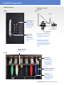
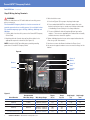
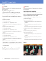
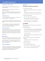
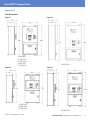
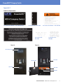
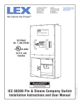
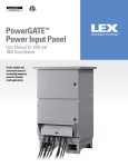
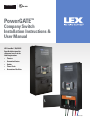
PowerGATE™
Switches & Panels
PowerGATE™
Company Switch
Installation Instructions &
User Manual
US Patent No. 7,136,278 B2
Specifically designed for
safe power access in the
following locations:
• Theaters
• Convention Centers
• Studios
• Theme Parks
• Recreational Facilities
LM-CS-000
PowerGATE™ Company Switch
Contents
Important:
2Contents
This manual contains information critical to the proper installation
and operation of the Lex Products PowerGATE™ Company Switch. Be
certain to read and understand all instructions prior to installation
and operation.
3
Prior to Installation
3
Shipment: Unpacking and Inspection
4 - 5
Product Features
6 - 9
Installation
10
Set Up - Making Lug Connections
10 - 11 Set Up - Making Cam Connections
11
Disconnection - Disconnecting Connections
12 Changing the Trip Current
12Troubleshooting
12
Limited Warranty
12Maintenance
12
Technical Support
Appendices
12
Pre-Operation and Maintenance Checklist
13
Parts Dimensions
14
Represented Model Numbers
15
Labels for Replacement
2
Contact Lex Products: 800.643.4460 [email protected]
This manual is furnished exclusively to support installation and
operation of the Lex Products PowerGATE Company Switch. All
concepts and ideas are the sole property of Lex Products and are
not to be duplicated or utilized in any manner without written
permission.
PowerGATE™ Company Switch
Prior to Installation: Site Preparation
Shipment: Unpacking and Inspection
Prepare installation site according to local codes.
Note: Be careful in the use of sharp object when cutting packaging
as damage to the outer coating may result.
The PowerGATE Company Switch is to be secured to a structure
using appropriate 3/8“ fasteners (See Figures 11 through 14).
The surface where the PowerGATE Company Switch is to be secured
must be capable of supporting the weight of the device as well as
the cable attached to it.
Perform a visual inspection to ensure the keylocks and doors are in
functioning condition and that the panel integrity is intact.
The following should be taken into consideration when locating the
PowerGATE Company Switch:
– The PowerGATE Company Switch is available in both and interior
(Type 1) and exterior (Type 3R) configurations. Be certain to select
the appropriate device for the given install location.
– Identify and meet local codes and local Authority Having
Jurisdiction (AHJ).
– The mounting location is to be carefully selected to allow
convenient connection between the PowerGATE Company Switch
and those devices that are to draw power from it.
– Proper clearance must be allowed in front of the PowerGATE
Company Switch to allow for operation of access doors and
attachment of externally connected cables. The clearance should
be no less than six (6) feet from the face of the panel and no less
than two (2) feet beneath the panel.
– While keylock protection is provided, access by unauthorized
personnel and vandals should be taken into consideration when
locating this device.
Contact Lex Products: 800.643.4460 [email protected]
3
PowerGATE™ Company Switch
Product Features
Figure 2
Figure 1
100% Rated
Electronic Circuit
Breaker 65,000 AIC
rating
cULus Listed for
intended use
Cam-type and lug
connections housed
behind lockable
door to prevent
exposed live
connections
Lock for restricting
access
Figure 3
Cable entry holes are
smooth to protect cable
from damage
4
Contact Lex Products: 800.643.4460 [email protected]
PowerGATE™ Company Switch
Product Features
Cam/Lug Connection
Chamber
Figure 4
Figure 5
SIDE VIEW
Indicator lights signal
whether power is
on or off and ground
presence (one light
for each phase, one
for grounding)
LUG OPENING FOR
BARE END CABLE
CAM TYPE FEMALE
CONNECTOR
Stainless Steel
Handles prevent
tripping of circuit
breaker handle
through incidental
contact
The exclusive cam/lug connection
combination is at the heart of the
PowerGATE™ Company Switch.
The detachable Cam-type outlet
and the direct wire lug have
been combined in a compact and
convenient arrangement, providing
a host of unique features and
benefits.
Cam-type receptacle
and lug combination
for bare end wire
Figure 6
Auto Shut-Off
interlock switch to
main breaker shuts
off power when door
opened; prevents
making or breaking
a connection under
load
Automatic chamber light
enhances visibility when
making connections
Strain relief secures
cable connections and
prevents cables from
being pulled out of the
connection lugs
Contact Lex Products: 800.643.4460 [email protected]
5
PowerGATE™ Company Switch
Installation
The installation of the PowerGATE Company Switch should
be carried out by qualified personnel in accordance with
local electrical codes.
Step 1: Fasten the PowerGATE Company Switch to
secure location
NOTE: The PowerGATE Company Switch can weigh as much
as 130 lbs. without cables attached.
1. T he panel should be located so there is adequate room for the
externally connected cables to hang below the panel.
A. Typically allow a minimum of 24” clearance from the bottom of
the panel to finished ground level
B. A mounting height of 44” A.F.F. is recommended wherever
conditions allow
4. It is recommended that a knockout punch be used to cut hole for
conduit
A. Cover the main switch to prevent metal shaving intrusion
B. Place the punch on the inside of the enclosure and draw the
punch through to the die on the outside.
5. Vacuum entire upper chamber to ensure no shavings are left
behind
Figure 7
Figure 8
2. Installation must be level and plumb
3. F astening onto a wall using 3/8” fasteners must be completed
prior to proceeding with any terminations (See Figures 10 through
13 for hole spacing)
Step 2: Installing the Conduit
NOTE: Conduit to enter through the top of the device (See
Figure 9).
NOTE: To maintain TYPE 3R Rating compliance for the
relevant enclosure, proper sealing procedures must be
followed. This is to include, but not limited to, the use of
proper gaskets.
NOTE: In order to prevent enclosure damage and to maintain
the enclosure requirements, the conduit must be aligned to
prevent unnecessary stress on the enclosure walls.
Figure 9
1. U
nfasten the upper front panel by removing the twenty (20)
Phillips-headed 10-32 x 1/2” screws securing it (See Figure 7
and 8)
2. C onduit to be sized according to cabling rating
3. T he completed conduit, when connected to the box, must be
a minumum of one inch (1”) from any of the top edges of the
enclosure to ensure proper clearance (see Figure 9)
6
Contact Lex Products: 800.643.4460 [email protected]
Allow 1”
minumum from
all edges
PowerGATE™ Company Switch
Figure 11
Figure 10
CS-60F-CxDx1
CS-100F-CxDx1
CS-200F-CxDx1
CS-60F-D5PS1
CS-100F-D5PS1
Figure 12
CS-400F-CxDx1
Figure 13
CS-60F-CxDx3
CS-100F-CxDx3
CS-200F-CxDx3
CS-400F-CxDx3
NOTE: All measurements in inches
Contact Lex Products: 800.643.4460 [email protected]
7
PowerGATE™ Company Switch
Installation – Continued
Step 3: Wiring the Lug Terminals
WARNING
Ensure circuit breakers are OFF and locked out from utility power
prior to connection.
3. Cable installation notes:
A. S ee chart (Figure 15) for proper strip length and torque
B. F ine stranded cable MUST be sleeved in copper shim stock
before inserting into lugs or strands may interfere with threads
of the binding screw resulting in false torque indication
The PowerGATE Company Switch is for the connection of
portable power devices to utility power. It is available in four
(4) standard amperage types: 60 Amp, 100 Amp, 200 Amp and
400 Amp.
C. T he use of 600 kcmil cable will require different lugs and/or
reducers. These are not supplied by Lex Products but are readily
available from most electrical suppliers
1. P ull the cables from the utility source to the PowerGATE Company
Switch Panel
2. B eginning with the Ground, strip and install the cables in the
appropriate compression terminals (See Figure 14)
4. Tighten individual terminal screws to the torque indicated on the
chart using a 3/8” Allen wrench
NOTE: Conduit shall NOT be relied upon to provide grounding
protection to PowerGATE Company Switch
5. Continue to connect the Neutral and then the Phases (hots)
6. Vacuum entire upper chamber to ensure no metal shavings are left
behind
Figure 14
Phase A
(Black)
Neutral
Phase B
(Red)
Ground
Phase C
(Blue)
Figure 15
Circuit Breaker
Recommended
Min. Wire Guage
Wire Guage Range
Torque
(lb-in)
Torque
(kg-cm)
Strip Length
(in)
Strip Length
(cm)
60 Amp
2 AWG
350 kcmil - 6 AWG
275
317
1 1/8
2.9
100 Amp
2 AWG
350 kcmil - 6 AWG
275
317
1 1/8
2.9
200 Amp
4/0 AWG
350 kcmil - 6 AWG
275
317
1 1/8
2.9
400 Amp
500 kcmil
500 kcmil - 250 kcmil
250 kcmil - 3/0 kcmil
380
275
323
317
1 1/8
2.9
350 kcmil - 6 AWG
275
275
1 1/8
2.9
Ground & Neutral Lugs
8
Contact Lex Products: 800.643.4460 [email protected]
PowerGATE™ Company Switch
Installation – Continued
Step 4: Isolating the Chassis Ground
If you need to isolate the chassis from ground, proceed as follows:
Step 5: Review Pre-Operation Checklist under
Appendix A prior to operation (page 12)
The chassis ground (C.G.) termination is located next to the main
ground cable (see Figure 16). To isolate this ground:
Step 6: Once Pre-Operation Checklist is complete
finish assembly of panel
1. R emove the nut holding the chassis ground lug to the threaded stud
1. Fasten the upper front panel by securing the twenty (20) Phillipsheaded 10-32 x 1/2” screws securing it (See Figure 8 and 9)
2. W
rap the chassis ground mounting lug with listed electrical tape or
shrink wrap, if available
3. U
sing a plastic wire tie, secure the chassis ground to the main
ground cable
4. C heck to make sure that the chassis ground is secure and that it
cannot come into contact with any metal surfaces of the cabinet
(See Figure 16A)
Step 7: Powering Up
1. Turn the power lever to the ON position
A. LEDs for each phase as well as the ground continuity should be
lit.
Figure 16
Figure 16A
Main
Ground
Cable
Chassis
Ground
Contact Lex Products: 800.643.4460 [email protected]
9
PowerGATE™ Company Switch
Set-up
WARNING
WARNING
Ensure the circuit breaker is OFF and locked out from utility power
prior to connection.
Ensure the circuit breaker is OFF and locked out from utility power
prior to connection.
Step 8A: Making Lug Connections
Step 8B: Making Cam Connections
1. Unsecure keylock on lower chamber and open chamber door
1. Unsecure keylock on lower chamber and open chamber door
NOTE: As a safety feature of the PowerGATE Company Switch the
power will be tripped off when the door is opened
NOTE: As a safety feature of the PowerGATE Company Switch the
power will be tripped off when the door is opened.
2. F eed Ground (green) cable through appropriate port in bottom of
the unit
2. Feed Ground (green) cable through appropriate port in bottom
3. C omplete the connection
A. Cut the cable end square
3. Complete the connection
Proper connection (See Figure 17):
B. Strip the wire 1-1/2”. Do not nick any strands.
A. Grasp plug jacket and firmly insert cam connector into cam
receptacle
C. Insert the bare end into the lug and torque per the label on the
lug cover
B. P ush on cam plug jacket until connector fully seats in cam
receptacle
4. C omplete the Neutral (white) connection
A. Cut the cable end square
B. Strip the wire 1-1/2”. Do not nick any strands.
C. Insert the bare end into the lug and torque per the label on the
lug cover
5. Complete the Phase (hot) connections
A. Cut the cable end square
B. Strip the wire 1-1/2”. Do not nick any strands.
C. Insert the bare end into the lug and torque per the label on the
lug cover
C. Rotate plug connector jacket counterclockwise until it stops
4. Feed Neutral (white) cable(s) through appropriate port(s) in
bottom
5. Complete the Neutral (white) connection(s)
Proper connection (See Figure 17):
A. G
rasp plug jacket and firmly insert cam connector into cam
receptacle
B. P ush on cam plug jacket until connector fully seats in cam
receptacle
C. Rotate plug connector jacket counterclockwise until it stops
6. M
ake sure all connections are right and secure
7. Tighten thubscrews on strain relief until the cables are held firmly
A. Be certain to leave a little slack in the cable so there is no strain
on the lug connection
Step 9A: Close chamber door, secure the keylock
allowing cables to exit cable ports at bottom.
10
Contact Lex Products: 800.643.4460 [email protected]
Figure 17
PowerGATE™ Company Switch
Set-up – Continued
Disconnection
Step 8B: Making Cam Connections (continued)
Step 10: Disconnecting Circuits
6. F eed Phase (black, red and blue) cables through appropriate ports
in bottom
WARNING
7. Complete the Phase (hot) connections
Ensure the circuit breaker is OFF and locked out from utility power
prior to connection.
Proper connection (See Figure 17):
A. G
rasp plug jacket and firmly insert cam connector into cam
receptacle
B. P ush on cam plug jacket until connector fully seats in cam
receptacle
C. R otate plug connector jacket counterclockwise until it stops
8. Make sure all connections are right and secure
Step 9B: Close chamber door, secure the keylock
allowing cables to exit cable ports at bottom.
1. Unsecure keylock on lower chamber and open chamber door
NOTE: As a safety feature of the PowerGATE Company Switch the
power will be tripped off when the door is opened.
2. Loosen thubscrews on strain relief until the cables may move
freely if using bare wire
3. Disconnect the Phase (hot) connections, beginning with the
furthest to the right
4. Complete disconnect of ALL Phase connections and set aside prior
to proceeding
5. Disconnect the Neutral (white) connection.
6. Complete disconnect of ALL Neutral connections and set aside
prior to proceeding
7. Disconnect the Ground (green) connection.
8. Complete disconnect of the Ground connection and set aside prior
to proceeding
Step 11: Close chamber door, secure keylock.
Contact Lex Products: 800.643.4460 [email protected]
11
PowerGATE™ Company Switch
Changing the Trip Current
Appendix A
- The trip current of the PowerGATE Company Switch may be
adjusted in the field.
Pre-Operation and Maintenance Checklist
1. Visual inspection of enclosure
- Contact Lex Products Technical Services for instructions on
adjusting the trip current.
– Ensure the PowerGATE Company Switch is firmly secured to the
building
NOTE: The revised trip current rating will NOT be reflected on the
label [Lex Products Part Number LBL-CS(Amperage)] on the face of
the device.
– Review conduit connection for signs of loosening or leakage
Troubleshooting
- If the unit immediately trips off on power up, check to make sure
the lower panel door is closed and secured.
- If any or all LEDs do not light, and there is power to the unit, turn
main power switch off and check the fuses located to the left of the
LEDs.
- If the breaker appears to be tripping too quickly, possibly due
to inrush current, contact Lex Products Technical Services for
instructions on adjusting the trip delay time.
Limited Warranty
When this PowerGATE Company Switch is installed and operated
according to the manual’s instructions Lex Products will repair or
replace any of its mechanical or electrical parts if they are found
to be defective in material or workmanship within one year of the
purchase date.
Maintenance
The PowerGATE Company Switch will require periodic maintenance.
Lex Products recommends annual inspections to keep the panel in
safe operating condition. Lex Products recommends that the PreOperation and Maintenance Checklist under Appendix A serve as a
basis for annual inspection.
– Ensure enclosure is intact with no signs of fatigue or rusting
2. Open the lower chamber door
– E nsure the chamber is dry and free of debris
– E nsure that gaskets are pliable and no cracking exists
– E nsure that door hinges are secure and lubricated
– E nsure that the keylock is intact and operational
WARNING
Ensure the circuit breaker is OFF and locked out from utility power
prior to proceeding.
3. Remove dead front panel
– Ensure that all load terminals are securely fastened and that the
set screws are set at the torque rating as detailed in Figure 16
– Ensure electrical connections are intact with no signs of
corrosion or cracking
– Ensure there is no debris left over from drilling and that no tools
are left in cabinet
4. Review all safety labels and ensure that they are present
and legible
– S ee Appendix F for label nomenclature and location
– Replace as needed
5. Inspect all portable cables
Technical Support
–D
o not use cables if they appear frayed
Lex Products Technical Services are available to assist in resolving
issues by calling 1.855.LEX.1002 or emailing support@LexProducts.
com. For any other information, please call Lex Products at
1.800.643.4460 or e-mail [email protected].
–D
o not use cable if connectors or plug do not seat properly
12
Contact Lex Products: 800.643.4460 [email protected]
–D
o not use cables if any copper wiring is exposed
PowerGATE™ Company Switch
Appendix B
Parts Dimensions
Figure 19
Figure 18
Figure 20
CS-60F-CxDx1
CS-100F-CxDx1
CS-200F-CxDx1
CS-60F-D5PS1
CS-100F-D5PS1
CS-400F-CxDx1
Figure 21
CS-60F-CxDx3
CS-100F-CxDx3
CS-200F-CxDx3
CS-400F-CxDx3
NOTE: All measurements in inches
Contact Lex Products: 800.643.4460 [email protected]
13
PowerGATE™ Company Switch
Appendix C
Represented Model Numbers of PowerGate™ Indoor Company Switches
CS-60F-C5DB1
CS-100F-C5DB1
CS-200F-C5DB1
CS-400F-C5DB1
CS-60F-C5DB1-BLK
CS-100F-C5DB1-BLK
CS-200F-C5DB1-BLK
CS-400F-C5DB1-BLK
CS-60F-C5DG1
CS-100F-C5DG1
CS-200F-C5DG1
CS-400F-C5DG1
CS-60F-C5DG1-BLK
CS-100F-C5DG1-BLK
CS-200F-C5DG1-BLK
CS-400F-C5DG1-BLK
CS-60F-C5DS1
CS-100F-C5DS1
CS-200F-C5DS1
CS-400F-C5DS1
CS-60F-C5DS1-BLK
CS-100F-C5DS1-BLK
CS-200F-C5DS1-BLK
CS-400F-C5DS1-BLK
CS-60F-C6DB1
CS-100F-C6DB1
CS-200F-C6DB1
CS-400F-C6DB1
CS-60F-C6DB1-BLK
CS-100F-C6DB1-BLK
CS-200F-C6DB1-BLK
CS-400F-C6DB1-BLK
CS-60F-C6DG1
CS-100F-C6DG1
CS-200F-C6DG1
CS-400F-C6DG1
CS-60F-C6DG1-BLK
CS-100F-C6DG1-BLK
CS-200F-C6DG1-BLK
CS-400F-C6DG1-BLK
CS-60F-C6DS1
CS-100F-C6DS1
CS-200F-C6DS1
CS-400F-C6DS1
CS-60F-C6DS1-BLK
CS-100F-C6DS1-BLK
CS-200F-C6DS1-BLK
CS-400F-C6DS1-BLK
Model Number Key:
CS Company Switch
(Number)F (Amperage Rating) with Female Connectors
C(Number) D(Letter) 1 Series 16 Cams (Quantity of Cams) Direct Wire (Cam Configuration) Type 1 Device
Cam Configuration
B - Reverse Both Neutral and Ground
G - Reverse Ground Only
S - Straight (All Female Connectors)
Appendix D
Color No Entry - Tan, BLK - Black
Represented Model Numbers of PowerGate™ Outdoor Company Switches
CS-60F-C5DB3
CS-100F-C5DB3
CS-200F-C5DB3
CS-400F-C5DB3
CS-60F-C5DG3
CS-100F-C5DG3
CS-200F-C5DG3
CS-400F-C5DG3
CS-60F-C5DS3
CS-100F-C5DS3
CS-200F-C5DS3
CS-400F-C5DS3
CS-60FC6DB3
CS-100F-C6DB3
CS-200F-C6DB3
CS-400F-C6DB3
CS-60F-C6DG3
CS-100F-C6DG3
CS-200F-C6DG3
CS-400F-C6DG3
CS-60F-C6DS3
CS-100F-C6DS3
CS-200F-C6DS3
CS-400F-C6DS3
Model Number Key:
CS Company Switch
(Number)F (Amperage Rating) with Female Connectors
C(Number) D(Letter) 3 Series 16 Cams (Quantity of Cams) Direct Wire (Cam Configuration) Type 3 Device
Cam Configuration
B - Reverse Both Neutral and Ground
G - Reverse Ground Only
Appendix E
S - Straight (All Female Connectors)
Represented Model Numbers of PowerGATE™ Pin-and-Sleeve Company Switches
CS-60F-D5PS1
CS-100F-D5PS1
Model Number Key:
CS Company Switch
(Number)F (Amperage Rating) with Female Connectors
D5PS1 Direct Wire 5-Pin Pin-and-Sleeve Type 1 Device
14
Contact Lex Products: 800.643.4460 [email protected]
PowerGATE™ Company Switch
Appendix F
Labels for Replacement
Lex Products Part Number – LBL- CS(Amperage)
Lex Products PN – LBL-CSGC
Lex Products PN –
LBL-CSTQ
Lex Products Part Number – LBL-PGIP-W1
Lex Products PN –
LBL-0002
Lex Products Part Number – LBL-CSPQ
Figure 22
Figure 23
LBL-CS(Amperage)
LBL-PGIP-W1
LBL-CSPQ
LBL-CSGC
LBL-CSTQ
LBL-0002
Contact Lex Products: 800.643.4460 [email protected]
15
PowerGATE™ Company Switch
User Manual
PowerGATE™
Switches & Panels
TYPE 3R
Company Switch with Cam-Type Outlets Ordering Information
400 AMP
200 AMP
100 AMP
Catalog Number
(NEMA 1 Indoor)
CS-400F-C6DS1
CS-200F-C6DS1
CS-400F-C6DB1 (reverse ground neutral) CS-200F-C6DB1 (reverse ground neutral)
CS-100F-C6DS1
CS-100F-C6DB1 (reverse ground neutral)
Catalog Number
(NEMA 3R Weather
Resistant)
CS-400F-C6DS3
CS-200F-C6DS3
CS-400F-C6DB3 (reverse ground neutral) CS-200F-C6DB3 (reverse ground neutral)
CS-100F-C6DS3
CS-100F-C6DB3 (reverse ground neutral)
Rating
400 Amp, 3 Phase, 120/208Y VAC
200 Amp, 3 Phase, 120/208Y VAC
100 Amp, 3 Phase, 120/208Y VAC
Overcurrent Protection
65,000 AIC Main Breaker
100% Rated
65,000 AIC Main Breaker
100% Rated
65,000 AIC Main Breaker
100% Rated
Output
(6) 16 Series Cam-type devices:
Black – Hot
Blue – Hot
Red – Hot
(2) White – Neutral
Green – Ground
(6) 16 Series Cam-type devices:
Black – Hot
Blue – Hot
Red – Hot
(2) White – Neutral
Green – Ground
(6) 16 Series Cam-type devices:
Black – Hot
Blue – Hot
Red – Hot
(2) White - Neutral
Green - Ground
Cabinet Finish Color
Beige or matte black powder coat
For black finish, add suffix “-BLK”
to catalog number
Beige or matte black powder coat
For black finish, add suffix “-BLK”
to catalog number
Beige or matte black powder coat
For black finish, add suffix “-BLK” to
catalog number
Dimensions (Indoor)
Dimensions (Outdoor)
46.50” H x 20.27” W x 11.64” D
46.50” H x 20.27” W x 12.91” D
38.50” H x 20.27” W x 11.64” D
38.50” H x 20.27” W x 12.91” D
38.50” H x 20.27” W x 11.64” D
38.50” H x 20.27” W x 12.91” D
Approximate Weight
130 lbs.
123 lbs.
123 lbs.
NOTE: For 5 Wire, replace 6 with 5 in catalog number
Company Switch with IEC 60309 Pin & Sleeve Receptacle Ordering Information
100 AMP
60 AMP
Catalog Number
CS-100F-D5PS1
CS-60F-D5PS1
Rating
100 Amp, 3 Phase (H,H,H,N,G), 120/208Y VAC
60 Amp, 3 Phase (H,H,H,N,G), 120/208Y VAC
Overcurrent Protection
65,000 AIC Main Breaker100% Rated
65,000 AIC Main Breaker 100% Rated
Output
(1) 100 Amp, 3 Phase, 4 Pole, 5 Wire,
120/208Y IEC 60309 pin & sleeve receptacle;
(5) Lugs for bare wire connection, in parallel with
pin & sleeve receptacle
(1) 60 Amp, 3 Phase, 4 Pole, 5 Wire, 120/208Y IEC 60309 pin &
sleeve receptacle; (5) Lugs for bare wire connection, in parallel
with pin & sleeve receptacle
Cabinet Finish Color
Beige or matte black powder coat
For black finish, add suffix “-BLK” to catalog number
Beige or matte black powder coat
For black finish, add suffix “-BLK” to catalog number
Dimensions
38.50” H x 20.27” W x 11.64” D
38.50” H x 20.27” W x 11.64” D
Lex Products Corporation
15 Progress Drive
Shelton CT 06484
203.363.3738
203.363.3742 Fax
16
Contact Lex Products: 800.643.4460 [email protected]
Lex West
11847 Sheldon Street
Sun Valley, CA 91352
818.768.4474
818.768.4040 Fax
www.lexproducts.com
[email protected]
800.643.4460
© Copyright Lex Products 2014
Produced in the United States of America
05-30 All Rights Reserved.
Lex Products logo and lexproducts.com are
trademarks or registered trademarks of Lex Products
in the United States, other countries, or both.