1
Symbol MS4404/MS4407
Integration Guide
Symbol MS4404/MS4407
Integration Guide
72E-79851-02
Revision A
August 2007
ii
Symbol MS4404/MS4407 Integration Guide
© 2007 by Motorola, Inc. All rights reserved.
No part of this publication may be reproduced or used in any form, or by any electrical or mechanical means,
without permission in writing from Motorola. This includes electronic or mechanical means, such as
photocopying, recording, or information storage and retrieval systems. The material in this manual is subject to
change without notice.
The software is provided strictly on an “as is” basis. All software, including firmware, furnished to the user is on
a licensed basis. Motorola grants to the user a non-transferable and non-exclusive license to use each
software or firmware program delivered hereunder (licensed program). Except as noted below, such license
may not be assigned, sublicensed, or otherwise transferred by the user without prior written consent of
Motorola. No right to copy a licensed program in whole or in part is granted, except as permitted under
copyright law. The user shall not modify, merge, or incorporate any form or portion of a licensed program with
other program material, create a derivative work from a licensed program, or use a licensed program in a
network without written permission from Motorola. The user agrees to maintain Motorola’s copyright notice on
the licensed programs delivered hereunder, and to include the same on any authorized copies it makes, in
whole or in part. The user agrees not to decompile, disassemble, decode, or reverse engineer any licensed
program delivered to the user or any portion thereof.
Motorola reserves the right to make changes to any software or product to improve reliability, function, or
design.
Motorola does not assume any product liability arising out of, or in connection with, the application or use of
any product, circuit, or application described herein.
No license is granted, either expressly or by implication, estoppel, or otherwise under any Motorola, Inc.,
intellectual property rights. An implied license only exists for equipment, circuits, and subsystems contained in
Motorola products.
MOTOROLA and the Stylized M Logo and Symbol and the Symbol logo are registered in the US Patent &
Trademark Office. Bluetooth is a registered trademark of Bluetooth SIG. Microsoft, Windows and ActiveSync
are either registered trademarks or trademarks of Microsoft Corporation. All other product or service names
are the property of their respective owners.
Motorola, Inc.
One Motorola Plaza
Holtsville, New York 11742-1300
http://www.symbol.com
iii
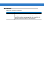
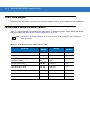
Revision History
Changes to the original manual are listed below:
Change
Date
Description
-01 Rev A
8/2006
Initial Release.
-02 Rev A
8/2007
Updated service information, updated drop specification, added DPM information
including decode ranges/zones and parameter, added SSI Interface chapter, added
new UPC/EAN supplemental options, changed RSS references to GS1 DataBar,
added following parameters: Bookland ISBN format, 4State Postal, Inverse 1D,
Data Matrix Inverse, Micro QR, QR Inverse, Aztec, Aztec Inverse.
iv
Symbol MS4404/MS4407 Integration Guide
Table of Contents
About This Guide
Overview........................................................................................................................
Chapter Descriptions .....................................................................................................
Notational Conventions..................................................................................................
Related Documents .......................................................................................................
Service Information........................................................................................................
xiii
xiii
xiv
xv
xv
Chapter 1: Getting Started
Overview .......................................................................................................................
Symbol MS440X Features ......................................................................................
Typical Applications ......................................................................................................
Theory of Operation ......................................................................................................
Block Diagrams .............................................................................................................
Block Diagrams .......................................................................................................
PL4407 Decoder .....................................................................................................
Power Management (Symbol MS4404 Only) ..........................................................
Serial I/O .................................................................................................................
1-1
1-2
1-2
1-2
1-3
1-3
1-5
1-5
1-6
Chapter 2: Installation
Overview .......................................................................................................................
Unpacking .....................................................................................................................
Mounting .......................................................................................................................
Symbol MS440X Mounting Dimensions ..................................................................
Connecting the MiniScan ..............................................................................................
Location and Positioning ...............................................................................................
Embedded Applications Requiring a Window ...............................................................
Window Material .....................................................................................................
Window Coatings ....................................................................................................
Embedded Window Angle and Position ..................................................................
Accessories ..................................................................................................................
Software Developer CD (Symbol MS4404 Only) ....................................................
2-1
2-1
2-2
2-2
2-3
2-4
2-4
2-4
2-5
2-6
2-8
2-9
vi
Symbol MS4404/MS4407 Integration Guide
Chapter 3: Imaging
Overview .......................................................................................................................
Aiming System ..............................................................................................................
Aiming Error ..................................................................................................................
Aiming Control ..............................................................................................................
Illumination System .......................................................................................................
Illumination Control .......................................................................................................
Focus Control ...............................................................................................................
Imaging Tips .................................................................................................................
Capturing Data ........................................................................................................
Beeper Signals .............................................................................................................
Supported Symbologies ................................................................................................
Operating Modes ..........................................................................................................
3-1
3-1
3-1
3-1
3-2
3-2
3-2
3-2
3-2
3-3
3-4
3-4
Chapter 4: Symbol MS4404/MS4407 Specifications
Electrical Interface ........................................................................................................
Symbol MS4404 Electrical Interface .......................................................................
Symbol MS4407 Electrical Interface .......................................................................
Mechanical Drawings ....................................................................................................
Symbol MS4404 Technical Specifications ....................................................................
Symbol MS4407 Imager Technical Specifications ........................................................
Skew, Pitch and Roll ...............................................................................................
Decode Zones ..............................................................................................................
Standard Near Focus ..............................................................................................
Standard Far Focus ................................................................................................
HD/DPM Near Focus ..............................................................................................
HD/DPM Far Focus .................................................................................................
4-1
4-1
4-3
4-4
4-6
4-8
4-10
4-11
4-11
4-13
4-15
4-17
Chapter 5: Maintenance & Troubleshooting
Overview ....................................................................................................................... 5-1
Maintenance ................................................................................................................. 5-1
Troubleshooting ............................................................................................................ 5-2
Chapter 6: User Preferences
Overview .......................................................................................................................
Host Selection .........................................................................................................
Changing Default Values ..............................................................................................
Imaging Sequence Examples .......................................................................................
Errors While Decoding ..................................................................................................
User Preferences Parameter Defaults ..........................................................................
User Preferences ..........................................................................................................
Set Default Parameter ............................................................................................
Parameter Scanning ...............................................................................................
Beeper Tone ...........................................................................................................
Beeper Volume .......................................................................................................
Trigger Mode ...........................................................................................................
Picklist Mode ...........................................................................................................
6-1
6-1
6-1
6-2
6-2
6-3
6-3
6-3
6-4
6-4
6-5
6-6
6-7
Table of Contents
Power Mode ............................................................................................................ 6-8
Time Delay to Low Power Mode ............................................................................. 6-8
Decode Session Timeout ........................................................................................ 6-9
Timeout Between Decodes, Same Symbol ............................................................ 6-10
Beep After Good Decode ........................................................................................ 6-10
Presentation Mode Session Timeout ...................................................................... 6-11
Chapter 7: Imager Preferences
Overview ....................................................................................................................... 7-1
Imaging Sequence Examples ....................................................................................... 7-2
Errors While Imaging .................................................................................................... 7-2
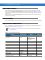
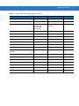
Imager Preferences Parameter Defaults ...................................................................... 7-2
Imager Preferences ...................................................................................................... 7-4
Operational Modes .................................................................................................. 7-4
Decode Mode .......................................................................................................... 7-4
Focus Mode ............................................................................................................ 7-5
Decoding Autoexposure .......................................................................................... 7-6
Decoding Illumination .............................................................................................. 7-6
Decode Aiming Pattern ........................................................................................... 7-7
DPM Scanning ........................................................................................................ 7-8
Image Capture Autoexposure ................................................................................. 7-9
Image Capture Illumination ..................................................................................... 7-9
Gain ........................................................................................................................ 7-10
Exposure Time ........................................................................................................ 7-11
LED Illumination ...................................................................................................... 7-12
Snapshot Mode Timeout ......................................................................................... 7-12
Snapshot Aiming Pattern ........................................................................................ 7-13
Image Cropping ...................................................................................................... 7-13
Crop to Pixel Addresses ......................................................................................... 7-14
Image Resolution .................................................................................................... 7-15
JPEG Image Options .............................................................................................. 7-16
JPEG Quality and Size Value ................................................................................. 7-16
Image File Format Selector ..................................................................................... 7-17
Bits per Pixel ........................................................................................................... 7-17
Signature Capture ................................................................................................... 7-18
Signature Capture File Format Selector ................................................................. 7-19
Signature Capture Bits per Pixel ............................................................................. 7-20
Signature Capture Width ......................................................................................... 7-20
Signature Capture Height ....................................................................................... 7-21
Signature Capture JPEG Quality ............................................................................ 7-21
Video View Finder ................................................................................................... 7-21
Target Video Frame Size ........................................................................................ 7-22
Video View Finder Image Size ................................................................................ 7-22
Chapter 8: SSI Interface
Overview ....................................................................................................................... 8-1
Communications ........................................................................................................... 8-1
vii
viii
Symbol MS4404/MS4407 Integration Guide
SSI Transactions ..........................................................................................................
General Data Transactions .....................................................................................
Transfer of Decode Data .........................................................................................
Communication Summary ............................................................................................
RTS/CTS Lines .......................................................................................................
ACK/NAK Option .....................................................................................................
Number of Data Bits ................................................................................................
Serial Response Time-out ......................................................................................
Retries .....................................................................................................................
Baud Rate, Stop Bits, Parity, Response Time-out, ACK/NAK Handshake .............
Errors ......................................................................................................................
Things to Remember When Using SSI Communication ...............................................
Selecting Time Delay to Low Power Mode using SSI ...................................................
Simple Serial Interface Default Parameters ..................................................................
SSI Host Parameters ....................................................................................................
Select SSI Host .......................................................................................................
Baud Rate ...............................................................................................................
Parity .......................................................................................................................
Check Parity ............................................................................................................
Software Handshaking ............................................................................................
Host RTS Line State ...............................................................................................
Decode Data Packet Format ...................................................................................
Stop Bit Select ........................................................................................................
Host Serial Response Time-out ..............................................................................
Host Character Time-out .........................................................................................
Multipacket Option ..................................................................................................
Event Reporting ............................................................................................................
Decode Event .........................................................................................................
Boot Up Event .........................................................................................................
Parameter Event .....................................................................................................
8-3
8-3
8-3
8-5
8-5
8-5
8-5
8-5
8-6
8-6
8-6
8-6
8-7
8-8
8-10
8-10
8-11
8-13
8-14
8-14
8-15
8-15
8-16
8-17
8-18
8-19
8-20
8-20
8-21
8-21
Chapter 9: Symbol MS4404 - RS-232 (Serial) Interface
Overview .......................................................................................................................
Serial Parameter Defaults .............................................................................................
Serial Host Parameters .................................................................................................
Serial Host Types ....................................................................................................
Baud Rate ...............................................................................................................
Parity .......................................................................................................................
Stop Bit Select ........................................................................................................
Data Bits .................................................................................................................
Check Receive Errors .............................................................................................
Hardware Handshaking ..........................................................................................
Software Handshaking ............................................................................................
Host Serial Response Time-out ..............................................................................
RTS Line State ........................................................................................................
Beep on <BEL> .......................................................................................................
Intercharacter Delay ................................................................................................
Nixdorf Beep/LED Options ......................................................................................
Ignore Unknown Characters ...................................................................................
9-1
9-2
9-3
9-5
9-6
9-8
9-8
9-9
9-9
9-10
9-12
9-14
9-15
9-15
9-16
9-17
9-17
Table of Contents
ASCII Character Set for Serial Hosts ............................................................................ 9-18
Chapter 10: Symbol MS4407 - USB Interface
Overview ....................................................................................................................... 10-1
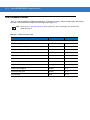
USB Parameter Defaults ............................................................................................... 10-2
USB Host Parameters ................................................................................................... 10-3
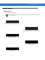
USB Device Type .................................................................................................... 10-3
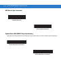
Symbol Native API (SNAPI) Status Handshaking ................................................... 10-4
USB Country Keyboard Types (Country Codes) .................................................... 10-5
USB Keystroke Delay ............................................................................................. 10-7
USB CAPS Lock Override ...................................................................................... 10-7
USB Ignore Unknown Characters ........................................................................... 10-8
Emulate Keypad ...................................................................................................... 10-8
USB Keyboard FN 1 Substitution ............................................................................ 10-9
Function Key Mapping ............................................................................................ 10-9
Simulated Caps Lock .............................................................................................. 10-10
Convert Case .......................................................................................................... 10-10
ASCII Character Set for USB ........................................................................................ 10-11
Chapter 11: Symbologies
Overview ....................................................................................................................... 11-1
Imaging Sequence Examples ....................................................................................... 11-2
Errors While Imaging .................................................................................................... 11-2
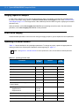
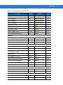
Symbology Parameter Defaults .................................................................................... 11-2
UPC/EAN ...................................................................................................................... 11-7
Enable/Disable UPC-A ............................................................................................ 11-7
Enable/Disable UPC-E ............................................................................................ 11-7
Enable/Disable UPC-E1 .......................................................................................... 11-8
Enable/Disable EAN-8/JAN-8 ................................................................................. 11-8
Enable/Disable EAN-13/JAN-13 ............................................................................. 11-9
Enable/Disable Bookland EAN ............................................................................... 11-9
Decode UPC/EAN/JAN Supplementals .................................................................. 11-10
User-Programmable Supplementals ....................................................................... 11-13
UPC/EAN/JAN Supplemental Redundancy ............................................................ 11-14
Transmit UPC-A Check Digit .................................................................................. 11-14
Transmit UPC-E Check Digit .................................................................................. 11-15
Transmit UPC-E1 Check Digit ................................................................................ 11-15
UPC-A Preamble .................................................................................................... 11-16
UPC-E Preamble .................................................................................................... 11-17
UPC-E1 Preamble .................................................................................................. 11-18
Convert UPC-E to UPC-A ....................................................................................... 11-19
Convert UPC-E1 to UPC-A ..................................................................................... 11-19
EAN-8/JAN-8 Extend .............................................................................................. 11-20
Bookland ISBN Format ........................................................................................... 11-21
UCC Coupon Extended Code ................................................................................. 11-22
Code 128 ...................................................................................................................... 11-22
Enable/Disable Code 128 ....................................................................................... 11-22
ix
x
Symbol MS4404/MS4407 Integration Guide
Enable/Disable UCC/EAN-128 ...............................................................................
Enable/Disable ISBT 128 ........................................................................................
Code 39 ........................................................................................................................
Enable/Disable Code 39 .........................................................................................
Enable/Disable Trioptic Code 39 ............................................................................
Convert Code 39 to Code 32 ..................................................................................
Code 32 Prefix ........................................................................................................
Set Lengths for Code 39 .........................................................................................
Code 39 Check Digit Verification ............................................................................
Transmit Code 39 Check Digit ................................................................................
Code 39 Full ASCII Conversion ..............................................................................
Code 39 Buffering (Scan & Store) ..........................................................................
Code 93 ........................................................................................................................
Enable/Disable Code 93 .........................................................................................
Set Lengths for Code 93 .........................................................................................
Code 11 ........................................................................................................................
Code 11 ..................................................................................................................
Set Lengths for Code 11 .........................................................................................
Code 11 Check Digit Verification ............................................................................
Transmit Code 11 Check Digits ..............................................................................
Interleaved 2 of 5 (ITF) .................................................................................................
Enable/Disable Interleaved 2 of 5 ...........................................................................
Set Lengths for Interleaved 2 of 5 ...........................................................................
I 2 of 5 Check Digit Verification ...............................................................................
Transmit I 2 of 5 Check Digit ...................................................................................
Convert I 2 of 5 to EAN-13 ......................................................................................
Discrete 2 of 5 (DTF) ....................................................................................................
Enable/Disable Discrete 2 of 5 ................................................................................
Set Lengths for Discrete 2 of 5 ...............................................................................
Codabar (NW - 7) .........................................................................................................
Enable/Disable Codabar .........................................................................................
Set Lengths for Codabar .........................................................................................
CLSI Editing ............................................................................................................
NOTIS Editing .........................................................................................................
MSI ...............................................................................................................................
Enable/Disable MSI ................................................................................................
Set Lengths for MSI ................................................................................................
MSI Check Digits ....................................................................................................
Transmit MSI Check Digit(s) ...................................................................................
MSI Check Digit Algorithm ......................................................................................
Inverse 1D ....................................................................................................................
Postal Codes ................................................................................................................
US Postnet ..............................................................................................................
US Planet ................................................................................................................
UK Postal ................................................................................................................
Transmit UK Postal Check Digit ..............................................................................
Japan Postal ...........................................................................................................
Australian Postal .....................................................................................................
Dutch Postal ............................................................................................................
4State Postal ...........................................................................................................
11-23
11-24
11-25
11-25
11-25
11-26
11-26
11-27
11-29
11-29
11-30
11-31
11-34
11-34
11-34
11-36
11-36
11-36
11-38
11-39
11-39
11-39
11-40
11-42
11-42
11-43
11-43
11-43
11-44
11-46
11-46
11-46
11-48
11-48
11-49
11-49
11-50
11-52
11-52
11-53
11-54
11-55
11-55
11-55
11-56
11-56
11-57
11-57
11-58
11-58
Table of Contents
Transmit US Postal Check Digit .............................................................................. 11-59
GS1 DataBar (Formerly RSS, Reduced Space Symbology) ........................................ 11-60
GS1 DataBar-14 ..................................................................................................... 11-60
GS1 DataBar Limited .............................................................................................. 11-60
GS1 DataBar Expanded ......................................................................................... 11-61
Convert GS1 DataBar to UPC/EAN ........................................................................ 11-61
Composite ..................................................................................................................... 11-62
Composite CC-C ..................................................................................................... 11-62
Composite CC-A/B .................................................................................................. 11-62
Composite TLC-39 .................................................................................................. 11-63
UPC Composite Mode ............................................................................................ 11-63
Composite Beep Mode ........................................................................................... 11-64
UCC/EAN Code 128 Emulation Mode for UCC/EAN Composite Codes ................ 11-65
2-D Symbologies ........................................................................................................... 11-66
Enable/Disable PDF417 .......................................................................................... 11-66
Enable/Disable MicroPDF417 ................................................................................. 11-66
Code 128 Emulation ............................................................................................... 11-67
Data Matrix .............................................................................................................. 11-68
Data Matrix Inverse ................................................................................................. 11-68
Maxicode ................................................................................................................. 11-69
QR Code ................................................................................................................. 11-70
MicroQR .................................................................................................................. 11-70
QR Inverse .............................................................................................................. 11-71
Aztec ....................................................................................................................... 11-71
Aztec Inverse .......................................................................................................... 11-72
Redundancy Level ........................................................................................................ 11-73
Security Level ............................................................................................................... 11-75
Intercharacter Gap Size .......................................................................................... 11-76
Report Version .............................................................................................................. 11-76
Macro PDF Features ..................................................................................................... 11-77
Macro PDF User Indications ................................................................................... 11-77
Macro PDF Transmit / Decode Mode Symbols ....................................................... 11-78
Transmit Macro PDF Control Header ..................................................................... 11-79
Escape Characters ................................................................................................. 11-79
Flush Macro Buffer .................................................................................................. 11-80
Abort Macro PDF Entry ........................................................................................... 11-80
Chapter 12: Miscellaneous Imager Options
Introduction ................................................................................................................... 12-1
Imaging Sequence Examples ....................................................................................... 12-1
Errors While Imaging .................................................................................................... 12-2
Miscellaneous Imager Parameter Defaults ................................................................... 12-2
Miscellaneous Imager Parameters ............................................................................... 12-3
Transmit Code ID Character ................................................................................... 12-3
Prefix/Suffix Values ................................................................................................. 12-4
Scan Data Transmission Format ............................................................................ 12-5
FN1 Substitution Values ......................................................................................... 12-6
Transmit “No Read” Message ................................................................................. 12-7
xi
xii
Symbol MS4404/MS4407 Integration Guide
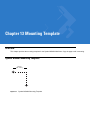
Chapter 13: Mounting Template
Overview ....................................................................................................................... 13-1
Symbol MS440X Mounting Template ........................................................................... 13-1
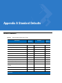
Appendix A: Standard Defaults
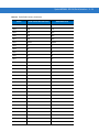
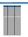
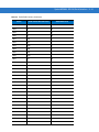
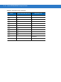
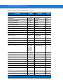
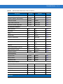
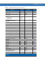
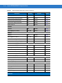
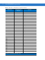
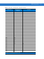
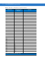
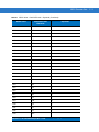
Default Parameters ....................................................................................................... A-1
Reserved Parameters ................................................................................................... A-10
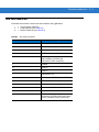
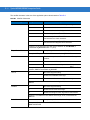
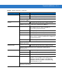
Appendix B: Programming Reference
Symbol Code Identifiers ................................................................................................ B-1
AIM Code Identifiers ..................................................................................................... B-3
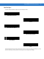
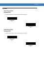
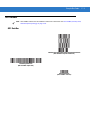
Appendix C: Sample Bar Codes
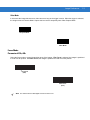
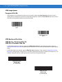
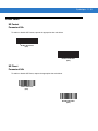
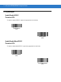
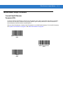
Code 39 ........................................................................................................................
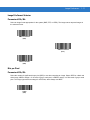
UPC/EAN ......................................................................................................................
UPC-A, 100% ..........................................................................................................
EAN-13, 100% ........................................................................................................
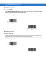
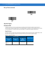
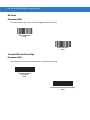
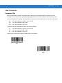
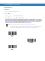
Code 128 ......................................................................................................................
Interleaved 2 of 5 ..........................................................................................................
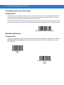
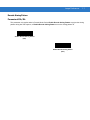
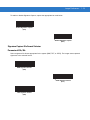
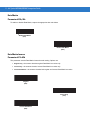
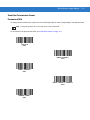
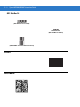
GS1 DataBar ................................................................................................................
GS1 DataBar ...........................................................................................................
GS1 DataBar-14 .....................................................................................................
PDF417 .........................................................................................................................
Data Matrix ...................................................................................................................
Maxicode ......................................................................................................................
C-1
C-1
C-1
C-1
C-2
C-2
C-3
C-3
C-4
C-4
C-4
C-5
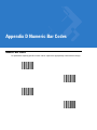
Appendix D: Numeric Bar Codes
Numeric Bar Codes ...................................................................................................... D-1
Cancel ........................................................................................................................... D-3
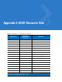
Appendix E: ASCII Character Sets
Glossary
Index
About This Guide
Overview
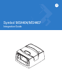
The Symbol MS4404/MS4407 Integration Guide provides general instructions for mounting and setting up the
Symbol MS4404 and MS4407 MiniScan imagers.
NOTE Unless otherwise noted, all instructions, drawings, bar codes, theory of operation, and features
documented in this guide apply to both the Symbol MS4404 and MS4407.
Chapter Descriptions
• Chapter 1, Getting Started provides an overview of the Symbol MS4404 and MS4407 imagers, including a
theory of operation.
• Chapter 2, Installation provides information on unpacking, mounting, and installing the Symbol MS440X.
• Chapter 3, Imaging provides information on aiming, illumination, focus control, data capture, beeper and
decode LED signals, supported symbologies and operating modes.
• Chapter 4, Symbol MS4404/MS4407 Specifications includes technical specifications, electrical interface,
mechanical drawings and decode zones.
• Chapter 5, Maintenance & Troubleshooting includes maintenance requirements and troubleshooting.
• Chapter 6, User Preferences provides programming bar codes for selecting user preference features.
• Chapter 7, Imager Preferences provides programming bar codes for selecting imager preference features.
• Chapter 8, SSI Interface describes the system requirements of the Simple Serial Interface (SSI), which
provides a communications link between Motorola decoders (e.g., scan engines, slot scanners, hand-held
scanners, two-dimensional scanners, hands-free scanners, and RF base stations) and a serial host.
• Chapter 9, Symbol MS4404 - RS-232 (Serial) Interface describes how to set up the Symbol MS4404 with a
serial host. The serial interface is used to connect the imager to point-of-sale devices, host computers, or
other devices with an available serial port (e.g., com port).
• Chapter 10, Symbol MS4407 - USB Interface describes how to set up the Symbol MS4407 with a USB host.
The imager connects directly to a USB host, or a powered USB hub, and is powered by it. No additional
power supply is required.
xiv
Symbol MS4404/MS4407 Integration Guide
• Chapter 11, Symbologies describes all symbology features and provides the programming bar codes
necessary for selecting these features.
• Chapter 12, Miscellaneous Imager Options includes commonly used bar codes to customize how data is
transmitted to the host device.
• Chapter 13, Mounting Template provide the mounting templates for the Symbol MS440X imager.
• Appendix A, Standard Defaults provides a table of all host devices and miscellaneous defaults.
• Appendix B, Programming Reference provides a table of AIM code identifiers, ASCII character conversions,
and keyboard maps.
• Appendix C, Sample Bar Codes includes sample bar codes.
• Appendix D, Numeric Bar Codes includes numeric bar codes to use with parameters requiring specific
numeric values. This chapter also includes the Cancel bar code.
• Appendix E, ASCII Character Sets provides ASCII character value tables.
Notational Conventions
The following conventions are used in this document:
• The terms “MS440X,” “imager,” and “MiniScan” refer to both the Symbol MS4404 and MS4407.
• Italics are used to highlight the following:
• Chapters and sections in this and related documents
• bullets (•) indicate:
- Action items
• Lists of alternatives
• Lists of required steps that are not necessarily sequential
• Sequential lists (e.g., those that describe step-by-step procedures) appear as numbered lists.
• Throughout the programming bar code menus, asterisks (*) are used to denote default parameter settings.
* Indicates Default
*Baud Rate 9600
Feature/Option
(06h)
Option Hex Value for
programming via SSI command
About This Guide
xv
Related Documents
The following documents provide more information for the MiniScan Series imagers.
• MiniScan Family of Scanners Quick Reference Guide, p/n 72-58809-xx
• Simple Serial Interface (SSI) Programmer’s Guide, p/n 72-40451-xx
• Simple Serial Interface (SSI) Developer’s Guide, p/n 72-50705-xx
For the latest version of this guide and all guides, go to: http://support.symbol.com.
Service Information
If you have a problem with your equipment, contact Motorola Enterprise Mobility Support for your region. Contact
information is available at: http://www.symbol.com/customersupport. If you purchased your Enterprise Mobility
business product from a Motorola business partner, contact that business partner for support.
Before contacting, have the model number and serial number at hand. If your problem cannot be solved by
Motorola Enterprise Mobility Support, you may need to return your equipment for servicing and will be given
specific directions.
Motorola is not responsible for any damages incurred during shipment if the approved shipping container is not
used. Shipping the units improperly can possibly void the warranty.
xvi
Symbol MS4404/MS4407 Integration Guide
Chapter 1 Getting Started
Overview
CAUTION
Use of controls, adjustments or procedures other than those specified here can result in
hazardous laser light exposure.
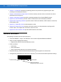
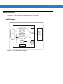
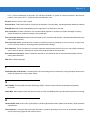
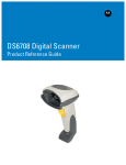
The Symbol MS440X fixed-mount imager is specifically designed for stand-alone applications, and OEM
applications such as kiosks. The imager is extremely compact, provides easy and flexible integration of bar code
imaging into a host device, and offers high-performance imaging on 1-D and 2-D bar codes. The Symbol MS440X
is ideal for medical instruments and manufacturing applications.
Figure 1-1 Symbol MS440X MiniScan Imager
This integration guide includes parameters and describes the theory of operation, installation, specifications, and
configuration.
1-2
Symbol MS4404/MS4407 Integration Guide
Symbol MS440X Features
• Stand-alone or OEM applications
• Quick and easy integration for OEM devices
• Excellent imaging performance on all 1-D and 2-D bar codes
• RS-232 (Serial) or USB Interface
• Direct part mark (DPM) support (DPM version only). Scan 2D symbols etched directly onto an item’s surface
(via laser etching and dot peening) for permanent identification.
• Easy programming and configuration
• Flexible mounting options
•
LEDs indicating power status and successful decodes.
Typical Applications
Fixed Mount Standalone Applications
• Clinical diagnostics
• Medical instruments
• Work stations
•
Assembly lines.
OEM Applications
• Kiosks / ATMs
• Music listening stations
• Medical instruments
• Clinical diagnostics
• Lottery terminals / gaming
•
Airline gate check-in.
Theory of Operation
During image capture:
1.
The imager sensor array contained in the SE4400 captures the image of the bar code through the optical
system.
2.
The PL4407 controls the SE4400 imager to obtain the best possible image quality.
3.
The PL4407 transfers the decoded data or image data to the host system.
The result is a monochrome digital image similar to that of a digital camera. The output from the SE4400 is byte wide
pixel data that is sent to the PL4407.
Getting Started
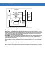
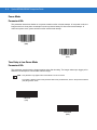
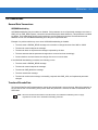
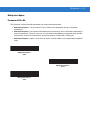
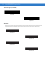
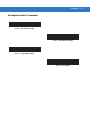
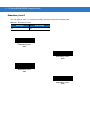
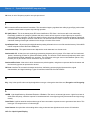
Block Diagrams
The MiniScan block diagrams illustrate the functional relationship of the MiniScan components. A detailed
description of each component in the block diagrams is also provided.
Block Diagrams
Interface Board
Voltage Regulator
Beeper
DB9
External Beeper
PL4407
Decoder
Interface Circuit
Red/
Green
LED
External Trigger
Figure 1-2 Symbol MS4404 Block Diagram
LED
Illumination
flex
SE4400
(Imager)
Data
Acquisition
Engine
1-3
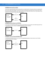
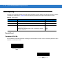
1-4
Symbol MS4404/MS4407 Integration Guide
.
Interface Board
Beeper
External Beeper
DB9
PL4407
Decoder
Red/
Green
LED
flex
SE4400
(Imager)
Data
Acquisition
Engine
External Trigger
Interface Circuit
LED
Illumination
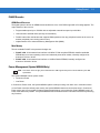
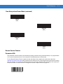
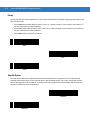
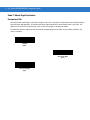
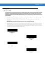
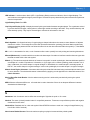
Figure 1-3 Symbol MS4407 Block Diagram
Miniscan Block Diagram Descriptions
Imager Engine - The SE4400 engine provides digital images which can be transmitted to a decoder to decode a
bar code of any format supported by the decoding software. The engine utilizes laser aiming and an LED illumination
system, and can switch between two focus positions for extended working range or for more precise focusing in
high-density bar code decoding or digital picture taking.
Interface Board - The interface board adapts the imager engine's interface into usable signals and data for the host.
It also contains a beeper. LED illumination and red/green LED for audio/visual feedback, and provides for an
external trigger and external beeper.
The Symbol MS4404 interface board converts TTL level SSI signals to proper RS-232 levels for connection to any
RS-232 compliant host, and the Symbol MS4407 interface board allows connection to logic level serial and USB
hosts.
Voltage Regulator (Symbol MS4404 only) - The power supply allows the Symbol MS4404 to operate of the
extended input voltages of 5 - 12 Vdc.
DB9 - The DB9 connector provides an outlet for the various interface signals used between a MiniScan and the host.
It also maintains pin compatibility with MiniScan (MSXXXX) host cables.
Getting Started
1-5
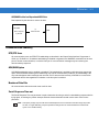
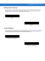
PL4407 Decoder
ARM9-Based Processor
The digital system is built on an ARM9 Harvard architecture core, 32 bit RISC engine with a five-stage pipeline. The
major features of the core are:
• Programmable speed up to 150 MHz with an adjustable external bus speed up to 96 MHz.
• 16K instruction and data cache (64-way set associative).
• Flexible internal bus architecture that supports DMA operations from any peripheral module to the core or to
another peripheral port including main memory.
•
Implementation of an enhanced Memory Management Unit (MMU).
Main Memory
The two available PL4407 microprocessor designs are:
• PL4407-x100: 32-bit external bus interface to 8 MB of PC100-compliant SDRAM, classified as Mobile
SDRAM due to its lower operating current and enhanced power-down modes; internally configured as
4 banks of 512 kb x 32 bits.
• PL4407-x200: 32-bit external bus interface to 16 MB of Mobile SDRAM; internally configured as
4 banks of 1024 Kb x 32 bits.
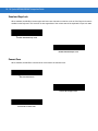
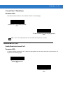
Power Management (Symbol MS4404 Only)
NOTE
This section does not apply to the USB interface. USB supports low power mode as defined by the USB
specification.
The Symbol MS4404 has two power modes:
• Continuous Power
•
Low Power.
In Continuous Power mode, the Symbol MS4404 system is always running even when not in a decode session.
In Low Power mode (the default power mode), the Symbol MS4404 draw less current than when in Continuous
Power mode, and is more suitable for battery-powered applications. In this mode the Symbol MS4404 enter Low
Power mode whenever possible. The Symbol MS4404 must be awakened from Low Power mode before performing
any functions.
1-6
Symbol MS4404/MS4407 Integration Guide
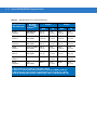
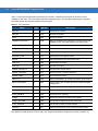
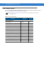
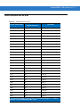
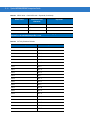
Table 1-1 describes how to put the Symbol MS4404 into Low Power mode; Table 1-2 describes how to awaken it.
Completely removing power from the Symbol MS4404 is not recommended; this should not be necessary as in Low
Power mode the Symbol MS4404 consume very little power (see Table 1-1).
Table 1-1 Placing the Symbol MS4404 into Low Power Mode
Action
Behavior
Set the Power Mode parameter to Low
Power (see Power Mode on page 6-8).
The Symbol MS4404 enters Low Power mode
automatically whenever possible.
Send the serial SLEEP command
(see the Simple Serial Interface (SSI)
Programmer Guide).
The Symbol MS4404 enters Low Power mode only
once, as soon as possible.
Note: All Wake Up signals (see Table 1-2) must be inactive to enter Low Power mode. Once the
Symbol MS4404 is awakened, at least 1 second (programmable time) must elapse before it
re-enters Low Power mode.
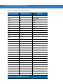
Table 1-2 Waking Up the Symbol MS4404
Signal
State to Wake Up
AIM/WKUP*
Low
TRIG*
Low
CTS*
Low
RXD
Send 0x00
When the Symbol MS4404 is awakened, it remains awake for at least 1 second (programmable time) before
re-entering Low Power mode; the host must perform its first action within this time period.
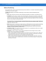
Serial I/O
Simple Serial Interface (SSI) Protocol is a half-duplex asynchronous serial interface with two hardware handshaking
lines. The four SSI-specific interface signals are:
• TXD - Transmitted Data
• RXD - Received Data
• RTS* - Request to Send
•
CTS* - Clear to Send
Signal names with the "*" modifier are asserted when at the positive logic 0 state (active low).
Signal names without the "*" modifier are asserted when at the positive logic 1 state (active high).
The TXD line transmits asynchronous serial data from the Symbol MS440X to the host.
The RXD line is used by the Symbol MS440X to receive asynchronous serial data from the host. The SSI protocol
does not support full-duplex data transfers; data is either transmitted or received by the Symbol MS440X, but never
both simultaneously.
The RTS* and CTS* signals help coordinate data transfers between the Symbol MS440X and the host.
Chapter 2 Installation
Overview
This chapter provides information on unpacking, mounting, and installing the MiniScan imager.
Unpacking
Remove the MiniScan from its packing and inspect for damage. If the imager is damaged, call Motorola Enterprise
Mobility Support on page xv.
KEEP THE PACKING. It is the approved shipping container and should be used if the equipment needs to be
returned for servicing.
2-2
Symbol MS4404/MS4407 Integration Guide
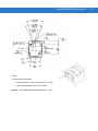
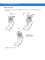
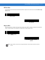
Mounting
There are two mounting holes (threaded inserts) on the bottom of the Symbol MS440X chassis.
The following figures provide mounting dimensions for the MiniScan housings. For a mounting template, see
Chapter 13, Mounting Template.
NOTE
Use only non-magnetic M3x.5 screws with a maximum length of 3.6mm to mount the MiniScan imager
chassis.
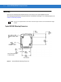
Symbol MS440X Mounting Dimensions
Note: Dimensions are
in inches [mm]
Exit Window
Figure 2-1 Symbol MS440X Mounting Dimensions
Getting Started
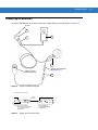
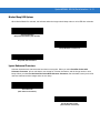
Connecting the MiniScan
To connect the MiniScan to the host, connect the imager cables in the order shown in Figure 2-2.
To Host
3
4
5
1
Trigger Jack (Optional)
See Figure 2-3
Trigger or Photo
Sensor (Optional)
2
Figure 2-2 Typical Connection Diagram
Male jack shown for reference
Insertion
Direction
1
1
2
3
2
3
Note: Due to many variations of
jack and socket styles, identify
terminals as shown before
soldering leads.
1 -1Ground
- Ground(Sleeve)
(Sleeve)
2 -2Vcc
(Middle
Contact)
- Battery
(Middle
Contact)
- Trigger(Tip)
(Tip)
3 -3Trigger
Figure 2-3 Trigger Jack Connector Pins
2-3
2-4
Symbol MS4404/MS4407 Integration Guide
Location and Positioning
The location and positioning guidelines provided do not consider unique application characteristics. It is
recommended that an opto-mechanical engineer perform an opto-mechanical analysis prior to integration.
NOTE
Integrate the imager in an environment no more extreme than the product’s specification, where the
imager will not exceed its temperature range. For instance, do not mount the imager onto or next to a large
heat source. When placing the imager with another device, ensure there is proper convection or venting
for heat. Follow these suggestions to ensure product longevity, warranty, and overall satisfaction with the
imager.
Embedded Applications Requiring a Window
Use the following guidelines for applications that require a window in front of the MiniScan.
NOTE
Motorola does not recommend placing an exit window in front of the MiniScan; however, the following
information is provided for applications that require such a window.
Window Material
NOTE
The window placement and material recommendations that follow should be considered if the Symbol
MS440X is mounted within a product with its own window.
Many window materials that look perfectly clear can contain stresses and distortions that can reduce imager
performance. For this reason, optical glass or cell-cast acrylic with an anti-reflection coating is highly
recommended. Following is a description of acrylic, and CR-39, another popular window material. Table 2-1
outlines the suggested window properties.
CAUTION
NOTE
Consult an opto-mechanical engineer to recommend an appropriate window material and to
determine if coatings are appropriate for the specific application.
Do not use polycarbonate material.
Acrylic
When fabricated by cell-casting, acrylic has very good optical quality and low initial cost. However, protect the
surface from the environment as acrylic is susceptible to attack by chemicals, mechanical stresses, and UV light.
Acrylic has reasonably good impact resistance and can be ultrasonically welded.
CR-39
CR-39 is a thermal-setting plastic produced by the cell-casting process, and is commonly used in plastic eye glasses
lenses. CR-39 has excellent chemical and environmental resistance, including good surface hardness. Typically it
does not require hard-coating, but can be hard coated for severe environments. CR-39 has reasonably good impact
resistance and cannot be ultrasonically welded.
Getting Started
2-5
Chemically Tempered Float Glass
Glass is a hard material which provides excellent scratch and abrasion resistance. However, unannealed glass is
brittle. Increasing flexibility strength with minimal optical distortion requires chemical tempering. Glass cannot be
ultrasonically welded and is difficult to cut into odd shapes.
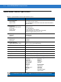
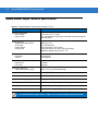
Table 2-1 Suggested Window Properties
Property
Description
Material
Clear cell-cast acrylic.
Spectral Transmission
85% minimum from 640 to 690 nanometers.
Thickness
0.059 ± 0.005
Wavefront Distortion (transmission)
0.2 wavelengths peak-to-valley maximum over any
0.08 in. diameter within the clear aperture.
Clear Aperture
To extend to within 0.04 in. of the edges all around.
Surface Quality
60-20 scratch/dig
Coating
Both sides to be anti-reflection coated to provide
0.5% max reflectivity (each side) from 640 to 690
nanometers at nominal window tilt angle. Coatings
must comply with the hardness adherence
requirements of MIL-M-13508.
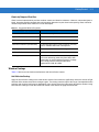
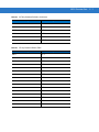
Window Coatings
Table 2-2 lists some exit window manufacturers and anti-reflection coaters.
Anti-Reflection Coatings
Apply an anti-reflection coating to the inside and/or outside of the window to significantly reduce the amount of light
reflected off the window, back into the imager engine. The coating can also improve the range of acceptable window
positions and minimize performance degradation due to signal loss as the light passes through the window. Using
anti-reflection coatings on both the inside and outside of the window is highly recommended.
2-6
Symbol MS4404/MS4407 Integration Guide
Polysiloxane Coating
Polysiloxane type coatings are applied to plastic surfaces to improve the surface resistance to both scratch and
abrasion. They are usually applied by dipping, then air-drying in an oven with filtered hot air.
Table 2-2 Window Manufacturers and Coaters
Company
Discipline
Specifics
Evaporated Coatings, Inc.
2365 Maryland Road
Willow Grove, PA 19090
(215) 659-3080
Anti-reflection coater
Acrylic window supplier
Anti-reflection coater
Fosta-Tek Optics, Inc.
320 Hamilton Street
Leominster, MA 01453
(978) 534-6511
Cell-caster, hard coater,
laser cutter
CR39 exit window
manufacturer
Glasflex Corporation
4 Sterling Road
Sterling, NJ 07980
(908) 647-4100
Cell-caster
Acrylic exit window
manufacturer
Optical Polymers Int. (OPI)
110 West Main Street
Milford, CT 06460
(203) 882-9093
CR-39 cell-caster, coater,
laser cutter
CR39 exit window
manufacturer
Polycast
70 Carlisle Place
Stamford, CT 06902
(800) 243-9002
acrylic cell-caster, hard
coater, laser cutter
Acrylic exit window
manufacturer
TSP
2009 Glen Parkway
Batavia, OH 45103
(800) 277-9778
acrylic cell-caster, coater,
laser cutter
Acrylic exit window
manufacturer
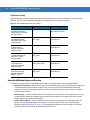
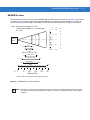
Embedded Window Angle and Position
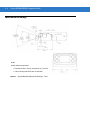
If a window is placed between the MiniScan and the item to be imaged, observe the following guidelines:
• Window Clear Opening - Make the clear opening of the window large enough so that the entire imager field
of view passes through the window. Cutting off any part of the field of view can degrade decode range
performance. Ensure that window placement relative to the MiniScan accounts for tolerances on all parts
involved in that assembly.
•
Window Angle - Angle the window at least 2o more than the tilt of the window on the imager (see Table 2-3).
Further tilting the window is acceptable and decreases the possibility of a secondary reflection from that
window degrading the imager's performance.
•
Optical Working Range - Adding a window can reduce the working range of the imager since there is a
signal loss when passing through window material. To minimize this reduction, use a special coating
described in Window Coatings on page 2-5. To understand the difference, test the imager in the desired
orientation and see if the difference affects imager performance.
Getting Started
Table 2-3 Secondary Window Angles
MiniScan Model
MS4404/MS4407
MiniScan Exit
Window Angle from
Vertical
Minimum
Secondary Window
Angle from Vertical
(distance > 2 mm)
0.5o
35o
Notes:
Unless otherwise specified:
• Dimensions are in inches, dimensions in [ ] are mm.
• User mounting tolerances are not included.
Figure 2-4 Symbol MS440X Optical Path and Exit Window
2-7
2-8
Symbol MS4404/MS4407 Integration Guide
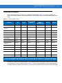
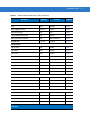
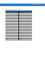
Accessories
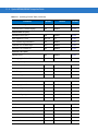
The following accessories are available for the MiniScan imager, and can be found in Symbol’s Solution Builder
(ordering guide).
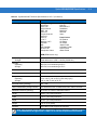
Table 2-4 MiniScan Imager Accessories
Accessory
Standard Part Number
ROHS Part Number
Power Supplies*
110V power supply, US
50-14000-008
50-14000-008R
220V power supply, Europe
50-14000-009
50-14000-009R
100V power supply, Asia
50-14000-010
50-14000-010R
264V Universal power supply
(also order cables below)
50-14001-001
50-14001-001R
DC line cord (power supply to imager)
50-16002-009
50-16002-009R
AC line cord (wall outlet to power supply)
23844-00-00
N/A
Female DB9 with straight connector to RS-232
host (female DB9), with trigger jack and no
beeper
25-13227-XX
25-13227-XXR
Female DB9 with straight connector to RS-232
host (female DB9), with trigger jack and beeper*
25-13228-XX
25-13228-XXR
Female DB9 with straight connector to RS-232
host (female DB9)
25-58918-XX
25-58918-XXR
Female DB9 with straight connector to RS-232
host (female DB9), with trigger jack and no
hardware handshaking
25-63736-XX
25-63736-XXR
Female DB9 with straight connector with trigger
jack and beeper to USB (Type A connector)
25-58925-XX
25-58925-XXR
Female DB9 straight to USB
25-58926-XX
25-58926-XXR
Female 25 pin D, TxD on pin 2
50-12100-378
N/A
Female 25 pin D, TxD on pin 3
50-12100-377
N/A
Male 25 pin D, TxD on pin 2
50-12100-380
N/A
Male 25 pin D, TxD on pin 3
50-12100-379
N/A
RS-232
USB
Cable Adapters
*For power connection, this device must be connected to a limited power source.
Note: DO NOT use cables with an integrated beeper when operating at 12 VDC.
Getting Started
2-9
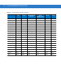
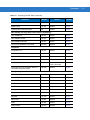
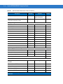
Table 2-4 MiniScan Imager Accessories (Continued)
Accessory
Standard Part Number
ROHS Part Number
Optional Accessories
Push button trigger cable
25-04950-XX
N/A
Photo sensor trigger cable
25-13176-XX
N/A
SW-60371-XX
N/A
Software
Software Developer's CD
*For power connection, this device must be connected to a limited power source.
Note: DO NOT use cables with an integrated beeper when operating at 12 VDC.
Software Developer CD (Symbol MS4404 Only)
The Software Developer CD provides the software tools required to integrate and communicate with the MiniScan
imagers, including:
•
Sample Windows® program with source code
•
DLL with source code for building user applications
•
ActiveX component (including help file) for easy integration into VisualBasic programs
•
Simple Serial Interface documentation.
With over 70 programmable parameters, you can configure MiniScan imagers using bar code menus, or through the
serial interface using Symbol’s Simple Serial Interface protocol.
For Windows®, DOS, and embedded system environments, the CD enables the user to take full advantage of the
imager’s features and obtain maximum performance.
2 - 10 Symbol MS4404/MS4407 Integration Guide
Chapter 3 Imaging
Overview
This chapter provides information on aiming, illumination, focus control, data capture, beeper and decode LED
signals, supported symbologies and operating modes.
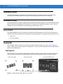
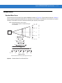
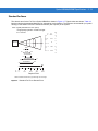
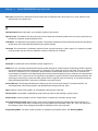
Aiming System
A 650 nm laser and a DOE generate a laser-aiming pattern which represents the imager's field of view throughout
its entire depth of field. The aiming subsystem uses a visible laser diode, a lens, and a diffractive optical element to
generate the aiming pattern. The pattern's center cross hairs indicates the center of the field of view.
Figure 3-1 Figure 1-2. Aiming Pattern
Aiming Error
The aiming pattern is designed to eliminate divergence (parallax) between the aiming axis and the imaging axis.
This method provides an aiming axis parallel to the imaging axis, while minimizing the offset between the two. See
Table 4-3 on page 4-6 and Table 4-4 on page 4-8 and for aiming element specifications.
Aiming Control
The aiming subsystem is under dynamic software control and is independent of the illumination subsystem.The
Symbol MS440X can capture images with both the aiming subsystem turned on (the image of the aiming pattern is
captured in the digital image) and the aiming subsystem turned off.
3-2
Symbol MS4404/MS4407 Integration Guide
Illumination System
An illumination subsystem, consisting of four red 635 nm LEDs, is provided to meet the image capture and
decoding requirements throughout the full range of ambient lighting (total darkness to full sunlight).
Illumination Control
The Symbol MS440X can capture images with the illumination subsystem turned on or off, accommodating images
that are close to the wavelength of the illumination. For example, since red LED illumination is used, it may be
desirable to shut off the illumination when capturing a printed image in red ink.
Focus Control
The Symbol MS440X has two focus positions controlled by an electromagnetic motor, which is under dynamic
software control and is independent of the illumination and aiming systems. The operating modes of the motor are:
• Near Focus
• Far Focus (default).
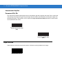
Imaging Tips
When imaging, ensure the symbol to be captured is within the decode range. See Location and Positioning on
page 2-4. Ensure the bar code is within the aiming pattern. The green decode LED lights and the imager beeps to
indicate a successful decode.
Capturing Data
Place the symbol in any orientation within the aiming pattern. Ensure the entire symbol is within the rectangular
area formed by the brackets in the aiming pattern. The red laser aiming pattern turns on to assist in aiming.
1D bar code symbol
2D bar code symbol
Aiming Pattern
Figure 3-2 Imager Aiming Pattern: Bar Code Centered
2D dot peen DPM symbol
Imaging
3-3
Incorrect
Correct
Figure 3-3 Imager Aiming Pattern: Bar Code Not Centered
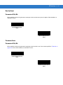
Beeper Signals
The BPR* output line is provided for user feedback, and provides 50 mA drive capability for an external beeper.
The Symbol MS440X's beeper ranges from 2.352 KHz to 2.963 KHz. The beeper output is a 50% duty cycle
square wave at maximum volume, 12.5% at low volume.
Table 3-1 Beeper Indications
Event
Beeper Indication
Decode
Middle Tone
Trigger is pulled
No sound
System bootup
Low Tone, Middle Tone, High Tone
Transmission error
Four Low Tones
Snapshot started
Low Tone
Snapshot completed
Low Tone
Entry error
Low Tone, High Tone
Parameter entered
High Tone, Low Tone, High Tone, Low Tone
Defaults set
High Tone, Low Tone, High Tone, Low Tone
Scanner expects a number
High Tone, Low Tone
No Decode message
No Sound
Video mode is on
No Sound
Video mode is off
No Sound
Scanner wakeup
No Sound
3-4
Symbol MS4404/MS4407 Integration Guide
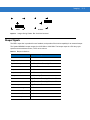
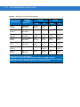
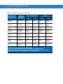
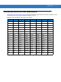
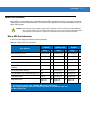
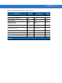
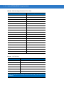
Supported Symbologies
Table 3-2 lists the bar code types supported by the imaging system. Each can be individually enabled or disabled.
Table 3-2 Supported Symbologies
Bookland EAN
Coupon Code
GS1 DataBar
Codabar
Data Matrix (ECC 200)
UPC/EAN
Code 11
Discrete 2 of 5
UCC/EAN 128
Code 39
Interleaved 2 of 5
US Planet
Code 39 Full ASCII
Maxicode
US Postnet
Trioptic Code 39
MicroPDF417
UK Postal
Code 93
PDF417
Australian Postal
Code 128
MSI Plessey
Japan Postal
Composite Codes
QR Code
Dutch Postal
Aztec (New in 2006)
Operating Modes
The imaging system supports the following operating modes. See Operational Modes on page 7-4 for the bar codes
to change between modes.
• Decode (default mode) - for decoding a bar code
• Snapshot - for capturing an image
• Video - provides a video of the subject
• Snapshot with Viewfinder Mode - provides a video of the subject until a snapshot of the image is captured.
Chapter 4 Symbol MS4404/MS4407
Specifications
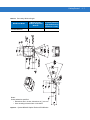
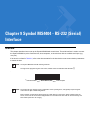
Electrical Interface
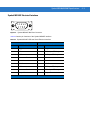
Symbol MS4404 Electrical Interface
Figure 4-1 Symbol MS4404 MiniScan Connector
4-2
Symbol MS4404/MS4407 Integration Guide
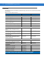
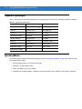
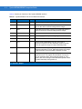
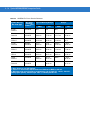
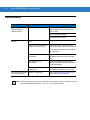
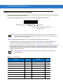
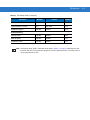
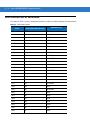
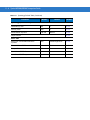
Table 4-1 lists the pin functions of the Symbol MS4404 interface.
Table 4-1 Symbol MS4404 True RS-232 Electrical Interface
Pin No.
Pin Name
Type*
Function
1
Trigger
I
Signals imager to begin decoding session.
2
TXD
O
Serial data transmit output. Drives the serial data receive
input on the device communicating with the imager.
3
RXD
I
Serial data receive input. Driven by the serial data transmit
output on the device communicating with the imager.
4
NC
5
Ground
6
Power
I
5.0 VDC - 12 VDC ± 10%
7
CTS
I
Clear-to-send handshaking input line, used only in
conjunction with the RTS line. Optionally used by another
device to signal the imager to begin transmitting data.
8
RTS
O
Request-to-send handshaking output line, used only in
conjunction with the CTS line. Optionally used by the imager
to signal another device that data is available to send.
9
Beeper/Download
I/O
During normal operation this signal functions as an external
beeper drive line. This signal can sink 50mA of current to
drive an external beeper, and is normally pulled up. This
signal is also used to begin Flash Download operation when
grounded externally during power up.
Power supply ground input and signal ground reference.
NC = No Connect (Do not connect this pin)
*I = Input O = Output
Symbol MS4404/MS4407 Specifications
Symbol MS4407 Electrical Interface
Figure 4-2 Symbol MS4407 MiniScan Connector
Table 4-2 lists the pin functions of the Symbol MS4407 interface.
Table 4-2 Symbol MS4407 USB and Serial Electrical Interface
USB Interface
Pin No.
Pin Name
Serial Interface
Pin No.
Pin Name
1
Trigger
1
Trigger
2
NC
2
TXD Output TTL Only
3
USB +
3
RXD Input TTL Only
4
Connect to Pin 8
4
NC
5
Ground
5
Ground
6
+5V Power
6
+5V Power
7
USB -
7
CTS Input TTL Only
8
Connect to Pin 4
8
RTS Output TTL Only
9
Beeper/Download
9
Beeper/Download
NC = No Connect (Do not connect this pin)
4-3
4-4
Symbol MS4404/MS4407 Integration Guide
Mechanical Drawings
Notes:
Unless otherwise specified:
• Dimensions are in inches, dimensions in [ ] are mm.
• User mounting tolerances are not included.
Figure 4-3 Symbol MS440X Mechanical Drawings - Part 1
Symbol MS4404/MS4407 Specifications
Notes:
Unless otherwise specified:
• Dimensions are in inches, dimensions in [ ] are mm.
• User mounting tolerances are not included.
Figure 4-4 Symbol MS440X Mechanical Drawings - Part 2
4-5
4-6
Symbol MS4404/MS4407 Integration Guide
Symbol MS4404 Technical Specifications
Table 4-3 Symbol MS4404 Technical Specifications at 23° C
Item
Power Requirements
Input Voltage
Input Current
Aiming Element
Visible Laser Diode (VLD)
VLD Power
Pattern Angle
Aiming Error
Description
4.5 V (min) to 13.2 V (max)
5 V in presentation mode active scan with external illumination;
260 mA (max)
650 nm ± 5 nm
0.7 mW Maximum
30.0º horizontal, 22.5º vertical
Total aiming error is 6.0 mm offset (horizontal)
Maximum angular aiming error is 1.5º
Field of View
Horizontal
Vertical
33.2 degrees
24.5 degrees
Focal Distance from Front of Engine
Near Focus
Far Focus
5 inches
9 inches
Illumination Element
Light Emitting Diode (LED)
635 nm ± 20 nm (Internal/External)
Image File Formats
BMP, TIFF, JPEG
Interface
True RS-232
Optical Resolution (gray scale)
640 (H) x 480 (V) pixels
Pitch Angle
± 60º from normal (see Figure 4-5 on page 4-10)
Roll
360º (see Figure 4-5 on page 4-10)
Skew Tolerance
± 50º from normal (see Figure 4-5 on page 4-10)
Symbologies
1-D Symbologies
UPC/EAN
Code 128
UCC.EAN128
GS1 DataBar
Code 39
Code 93
I 2 of 5
Discrete 2 of 5
Codabar
MSI
2-D Symbologies
Maxicode
PDF417
DataMatrix
QRCode
Postal Codes
US Postnet
US Planet
UK Postal
Australian Postal
Japan Postal
Note: Environmental and/or tolerance parameters are not cumulative. A thermal analysis
is recommended if the application is subject to an extreme temperature environment.
Symbol MS4404/MS4407 Specifications
Table 4-3 Symbol MS4404 Technical Specifications at 23° C (Continued)
Item
Description
Ambient Light Immunity
Sunlight
Total darkness to 9,000 ft. candles (96,900 lux)
Humidity
Operating
Storage
95% RH, non-condensing at 50º C
85% RH, non-condensing at 70º C
Shock
2000 ± 5% G
Drop
Multiple 30 in. (76.2 cm) drops to concrete
Temperature
Operating
Storage
-4º to 122º F (-20º to 50º C) (50% duty cycle)
-40º to 158º F (-40º to 70º C)
Electrical Safety (pending)
ETL, VDE
Laser Classification (aiming element)
It is intended for use in CDRH Class 2/IEC Class 1 devices.
Radiated Emissions (pending)
FCC Part 15 Class B, CISPIR22 Class B
Height
0.99 in. (25.2 mm) maximum
Width
1.91 in. (30.2 mm) maximum
Depth
2.18 in. (55.4 mm) maximum
Weight
1.8 oz. (51.0 grams)
Interface
9-pin Male D-sub supports all interfaces
Note: Environmental and/or tolerance parameters are not cumulative. A thermal analysis
is recommended if the application is subject to an extreme temperature environment.
4-7
4-8
Symbol MS4404/MS4407 Integration Guide
Symbol MS4407 Imager Technical Specifications
Table 4-4 Symbol MS4407 Technical Specifications at 23° C
Item
Power Requirements
Input Voltage
Input Current
Aiming Element
Visible Laser Diode (VLD)
VLD Power
Pattern Angle
Aiming Error
Description
4.5 V (min) to 5.5 V (max)
5 V in presentation mode active scan with external illumination;
245 mA (max)
650 nm ± 5 nm
0.7 mW Maximum
30.0º horizontal, 22.5º vertical
Total aiming error is 6.0 mm offset (horizontal)
Maximum angular aiming error is 1.5º
Field of View
Horizontal
Vertical
33.2 degrees
24.5 degrees
Focal Distance from Front of Engine
Near Focus
Far Focus
5 inches
9 inches
Illumination Element
Light Emitting Diode (LED)
635 nm ± 20 nm (Internal/External)
Image File Formats
BMP, TIFF, JPEG
Interface
0 - 5 V Serial (TTL 232), USB1.1
Optical Resolution (gray scale)
640 (H) x 480 (V) pixels
Pitch Angle
± 60º from normal (see Figure 4-5 on page 4-10)
Roll
360º (see Figure 4-5 on page 4-10)
Skew Tolerance
± 50º from normal (see Figure 4-5 on page 4-10)
Note: Environmental and/or tolerance parameters are not cumulative. A thermal analysis
is recommended if the application is subject to an extreme temperature environment.
Symbol MS4404/MS4407 Specifications
Table 4-4 Symbol MS4407 Technical Specifications at 23° C (Continued)
Item
Symbologies
Description
1-D Symbologies
UPC/EAN
Code 128
UCC.EAN128
ISBT 128
Code 39
Trioptic Code 39
Code 93
Code 11
I 2 of 5
Discrete 2 of 5
Codabar
MS
GS1 DataBar
Inverse 1DI
Composite Codes
2-D Symbologies
PDF417
MicroPDF417
DataMatrix
Maxicode
QRCode
Aztec
Postal Codes
US Postnet
US Planet
UK Postal
Japan Postal
Australian Postal
Dutch Postal
4State Postal
DPM (DPM version only).
Ambient Light Immunity
Sunlight
Total darkness to 9,000 ft. candles (96,900 lux)
Humidity
Operating
Storage
95% RH, non-condensing at 50º C
85% RH, non-condensing at 70º C
Shock
2000 ± 5% G
Drop
Multiple 30 in. (76.2 cm) drops to concrete
Temperature
Operating
Storage
-4º to 122º F (-20º to 50º C) (50% duty cycle)
-40º to 158º F (-40º to 70º C)
Electrical Safety (pending)
ETL, VDE
Laser Classification (aiming Element)
It is intended for use in CDRH Class 2/IEC Class 1 devices.
Radiated Emissions (pending)
FCC Part 15 Class B, CISPIR22 Class B
Height
0.99 in. (25.2 mm) maximum
Width
1.91 in. (30.2 mm) maximum
Depth
2.18 in. (55.4 mm) maximum
Weight
1.8 oz. (51.0 grams)
Interface
9-pin Male D-sub supports all interfaces
Note: Environmental and/or tolerance parameters are not cumulative. A thermal analysis
is recommended if the application is subject to an extreme temperature environment.
4-9
4 - 10 Symbol MS4404/MS4407 Integration Guide
Skew, Pitch and Roll
Measured on a 20 mil Code 39 symbol at a distance of 10 inches. Tolerance is reduced at extreme ends of the
working range.
Skew
+ 60° from normal
+ 50° from normal
Pitch
Roll
360°
Note: Tolerances are
reduced at extreme ends
of the working range.
Figure 4-5 Skew, Pitch and Roll
Symbol MS4404/MS4407 Specifications 4 - 11
Decode Zones
Standard Near Focus
The decode zone for the Near Focus Symbol MS440X is shown in Figure 4-6. Typical values are shown. Table 4-5
lists the typical and guaranteed distances for selected bar code densities. The minimum element width (or “symbol
density”) is the width in mils of the narrowest element (bar or space) in the symbol.
Note: Typical performance at 73°F (23°C)
on high quality symbols in normal room light.
Vcc = 5.0 Vdc
in.
cm
3.5
8.9
1.75 4.4
MS440X
0
0
1.75 4.4
2.7
5 mil
5.5
6.67 mil PDF417
3.0
2.2
3.0
2.0
6.0
10 mil PDF417
6.0
13 mil (100% UPC)
15 mil PDF417
*
3.5 8.9
5.25
7.5 mil
7.0
7.0
20 mil
9.5
*
In.
cm
0
0
2
5.1
4
10.2
6
15.2
8
20.3
10
25.4
Depth of Field
* Minimum distance determined by symbol length and scan angle.
Figure 4-6 Standard Near Focus Decode Zone
W
i
d
t
h
o
f
F
i
e
l
d
4 - 12 Symbol MS4404/MS4407 Integration Guide
Table 4-5
Standard Near Focus Decode Distances
Symbol Density/
Bar Code Type
Bar Code
Content/
ContrastNote 2
Typical Working
Ranges
Near
Far
Guaranteed Working
Ranges
Near
Far
5.0 mil
Code 39
ABCDEFGH
80% MRD
2.7 in
6.9 cm
5.5 in
14.0 cm
4.0 in
10.2 cm
5.0 in
12.7 cm
6.67 mil
PDF417
4 Col, 20 Rows
80% MRD
3.0 in
7.62 cm
5.25 in
13.3 cm
4.5 in
11.4 cm
5.0 in
12.7 cm
7.5 mil
Code 39
ABCDEF
80% MRD
2.2 in
5.6 cm
6.0 in
15.2 cm
3.5 in
8.9 cm
5.5 in
13.9 cm
10 mil
PDF417
3 Col, 17 Rows
80% MRD
3.0 in
7.6 cm
6.0 in
15.2 cm
4.0 in
10.2 cm
5.5 in
13.9 cm
13 mil
UPC-A
012345678905
80% MRD
2.0 in
5.1 cm
7.0 in
17.8 cm
3.0 in
7.6 cm
6.0 in
15.2 cm
15 mil
PDF417
80% MRD
Note 1
7.0 in
17.8 cm
Note 1
6.0 in
15.2 cm
20 mil
Code 39
123
80% MRD
Note 1
9.5 in
24.1 cm
Note 1
8.0 in
20.3 cm
Notes:
1. Near distances are field-of-view (FOV) limited.
2. Contrast is measured as Mean Reflective Difference (MRD) at 670 nm.
3. Working range specifications at temperature = 23°C, pitch=15°, roll=0°,
skew=0°, photographic quality, ambient light ~30 ft-c, humidity 45-70% RH.
Symbol MS4404/MS4407 Specifications 4 - 13
Standard Far Focus
The decode zone for the Far Focus Symbol MS440X is shown in Figure 4-7. Typical values are shown. Table 4-6
lists the typical and guaranteed distances for selected bar code densities. The minimum element width (or “symbol
density”) is the width in mils of the narrowest element (bar or space) in the symbol.
Note: Typical performance at 73°F (23°C)
on high quality symbols in normal room light.
Vcc = 5.0 Vdc
MS440X
in.
cm
8
20.3
4
10.2
W
i
d
t
h
0
0
o
f
4
10.2
8
20.3
5 mil
5.5
7.0
7.5 mil
3.5
9.0
10 mil PDF417
9.0
5.0
2.75
13 mil (100% UPC)
15 mil PDF417
*
13.5
12.0
20 mil
18.5
*
In.
cm
0
0
5
12.7
10
25.4
15
38.1
20
50.8
Depth of Field
* Minimum distance determined by symbol length and scan angle.
Figure 4-7 Standard Far Focus Decode Zone
F
i
e
l
d
4 - 14 Symbol MS4404/MS4407 Integration Guide
Table 4-6
Standard Far Focus Decode Distances
Symbol Density/
Bar Code Type
Bar Code
Content/
ContrastNote 2
Typical Working
Ranges
Near
Far
Guaranteed Working
Ranges
Near
Far
5.0 mil
Code 39
ABCDEFGH
80% MRD
5.5 in
13.9 cm
7.0 in
17.8 cm
N/A
N/A
6.67 mil
PDF417
4 Col, 20 Rows
80% MRD
N/A
N/A
N/A
N/A
7.5 mil
Code 39
ABCDEF
80% MRD
3.5 in
8.9 cm
9.0 in
22.9 cm
5.5 in
14.0 cm
7.0 in
17.8 cm
10 mil
PDF417
3 Col, 17 Rows
80% MRD
5.0 in
12.7 cm
9.0 in
22.9 cm
6.5 in
16.5 cm
8.0 in
20.3 cm
13 mil
UPC-A
012345678905
80% MRD
2.75 in
6.9 cm
13.5 in
34.3 cm
3.0 in
7.6 cm
11.5 in
29.2 cm
15 mil
PDF417
80% MRD
Note 1
12.0 in
30.5 cm
Note 1
11.0 in
27.9 cm
20 mil
Code 39
123
80% MRD
Note 1
18.5 in
46.9 cm
Note 1
15.5 in
39.4 cm
Notes:
1. Near distances are FOV limited.
2. Contrast is measured as Mean Reflective Difference (MRD) at 670 nm.
3. Working range specifications at temperature = 23°C, pitch=15°, roll=0°, skew=0°,
photographic quality, ambient light ~30 ft-c, humidity 45-70% RH.
Symbol MS4404/MS4407 Specifications 4 - 15
HD/DPM Near Focus
The decode zone for the Near Focus Symbol MS440X HD and DPM versions is shown in Figure 4-8. Typical
values are shown. Table 4-7 lists the typical and guaranteed distances for selected bar code densities. The
minimum element width (or “symbol density”) is the width in mils of the narrowest element (bar or space) in the
symbol.
Note: Typical perf ormance at 73°F (23°C)
on high quality symb
ols in nor mal room light.
Vcc = 3.3V
in.
cm
3.0
7.6
1.5 3.8
MS440X
DPM
4 mil PDF417
o
f
1.5 3.8
F
i
e
l
d
3.2
5 mil
1.7
2.0
4.0
6.67 mil PDF417
3.0 7.6
3.6
7.5 mil
1.6
4.3
10 mil PDF417
1.7*
4.0
13 mil (100% UPC)
2.2
15 mil PDF417
*
5.1
4.5
20 mil
7.0
*
In.
cm
0
0
2.4
0
0
1
2.5
2
10.2
3
7.6
W
i
d
t
h
4
10.2
5
12.7
6
15.2
7
17.8
8
20.3
Depth of Field
* Minimum distance deter mined by symbol length and sc
an angle .
Figure 4-8 HD/DPM Near Focus Decode Zone
NOTE
The decode zone performance for DPM shown above is based on controlled conditions and is to be used
as a guide only. Decoding is affected by mark quality, type, surface, and grade as well as ambient lighting
conditions.
4 - 16 Symbol MS4404/MS4407 Integration Guide
Table 4-7
HD/DPM Near Focus Decode Distances
Symbol Density/
Bar Code Type
Bar Code
Content/
ContrastNote 2
Typical Working Ranges
Near
Far
Guaranteed Working
Ranges
Near
Far
4.0 mil
PDF417
80% MRD
2.4 in
6.10 cm
3.2 in
8.13 cm
Note 1
2.74 in
6.96 cm
5.0 mil
Code 39
ABCDEFGH
80% MRD
1.7 in
4.32 cm
4.0 in
10.16 cm
2.29 in
5.82 cm
3.04 in
7.72 cm
6.67 mil
PDF417
4 Col, 20 Rows
80% MRD
2.0 in
5.08 cm
3.6 in
9.14 cm
2.74 in
6.96 cm
2.94 in
7.47 cm
7.5 mil
Code 39
ABCDEF
80% MRD
1.6 in
4.06 cm
4.3 in
10.92 cm
2.54 in
6.45 cm
3.54 in
8.99 cm
10 mil
PDF417
3 Col, 17 Rows
80% MRD
1.7 in Note 1
4.32 cm
4.0 in
10.16 cm
Note 1
3.04 in
7.72 cm
13 mil
UPC-A
012345678905
80% MRD
2.2 in
5.59 cm
5.1 in
12.95 cm
Note 1
4.04 in
10.26 cm
15 mil
PDF417
80% MRD
Note 1
4.5 in
11.43 cm
Note 1
3.79 in
9.63 cm
20 mil
Code 39
123
80% MRD
Note 1
7.0 in
17.78 cm
Note 1
5.29 in
13.44 cm
Notes:
1. Near distances are field-of-view (FOV) limited.
2. Contrast is measured as Mean Reflective Difference (MRD) at 670 nm.
3. Working range specifications at temperature = 23°C, pitch=15°, roll=0°, skew=0°,
photographic quality, ambient light ~30 ft-c, humidity 45-70% RH.
Symbol MS4404/MS4407 Specifications 4 - 17
HD/DPM Far Focus
The decode zone for the Far Focus Symbol MS440X HD and DPM versions is shown in Figure 4-9. Typical values
are shown. Table 4-8 lists the typical and guaranteed distances for selected bar code densities. The minimum
element width (or “symbol density”) is the width in mils of the narrowest element (bar or space) in the symbol.
Note: Typical perf ormance at 73°F (23°C)
on high quality symb
ols in nor mal room light.
Vcc = 3.3V
MS440X
DPM
3.5
5 mil
7.5 mil
3.8
2.7*
10 mil PDF417
3
7.6
15 mil PDF417
6
15.2
5.1
0
0
2
5.1
4
10.2
o
f
F
i
e
l
d
10.5
10.2
20 mil
0
0
2
W
i
d
t
h
9.0
14.5
*
In.
cm
10.2
9.0
13 mil (100% UPC)
2.5
cm
4
7.0
6.67 mil PDF417
7.1
4.0
2.7
in.
9
22.9
12
30.5
15
38.1
Depth of Field
* Minimum distance deter mined by symbol length and sc
an angle .
Figure 4-9 HD/DPM Far Focus Decode Zone
NOTE
The decode zone performance for DPM shown above is based on controlled conditions and is to be used
as a guide only. Decoding is affected by mark quality, type, surface, and grade as well as ambient lighting
conditions.
4 - 18 Symbol MS4404/MS4407 Integration Guide
Table 4-8
HD/DPM Far Focus Decode Distances
Guaranteed Working
Ranges
Bar Code
Content/
ContrastNote 2
Typical Working Ranges
4.0 mil
PDF417
80% MRD
N/A
N/A
N/A
N/A
5.0 mil
Code 39
ABCDEFGH
80% MRD
3.5 in
8.89 cm
7.0 in
17.78 cm
4.79 in
12.17 cm
6.29 in
15.98 cm
6.67 mil
PDF417
4 Col, 20 Rows
80% MRD
4.0 in
10.16 cm
7.1 in
18.03 cm
5.29 in
13.44 cm
5.79 in
14.71
7.5 mil
Code 39
ABCDEF
80% MRD
2.7 in
6.86 cm
9.0 in
22.86 cm
4.04 in
10.26 cm
7.29 in
18.52 cm
10 mil
PDF417
3 Col, 17 Rows
80% MRD
3.8 in
9.65 cm
9.0 in
22.86 cm
5.29 in
13.44 cm
7.04 in
17.88 cm
13 mil
UPC-A
012345678905
80% MRD
2.5 in
6.35 cm
10.5 in
26.67 cm
3.54 in
8.99 cm
8.29 in
21.06 cm
15 mil
PDF417
80% MRD
2.7 in Note 1
6.86 cm
10.2 in
25.91 cm
Note 1
7.79 in
19.79 cm
20 mil
Code 39
123
80% MRD
Note 1
14.5 in
36.83 cm
Note 1
11.54 in
29.31 cm
Symbol Density/
Bar Code Type
Near
Far
Near
Far
Notes:
1. Near distances are FOV limited.
2. Contrast is measured as Mean Reflective Difference (MRD) at 670 nm.
3. Working range specifications at temperature = 23°C, pitch=15°, roll=0°, skew=0°,
photographic quality, ambient light ~30 ft-c, humidity 45-70% RH.
Chapter 5 Maintenance & Troubleshooting
Overview
The chapter provides information on maintenance and troubleshooting.
Maintenance
Cleaning the exit window is the only maintenance required. Do not allow any abrasive material to touch the window.
Clean the exit window with a damp cloth and, if necessary, a non-ammonia based detergent.
5-2
Symbol MS4404/MS4407 Integration Guide
Troubleshooting
Problem
No red LED or nothing
happens during a
capture attempt.
Possible Cause
No power to the imager.
Possible Solutions
Check the system power.
Confirm that the correct host interface
cable is used.
Connect the power supply.
Re-connect loose cables.
Imager cannot read the
bar code.
Interface/power cables are
loose.
Re-connect loose cables.
Imager is not programmed for
the correct bar code type.
Ensure the imager is programmed to
read the type of bar code to be decoded.
Try capturing other bar code(s) and other
bar code types.
Laser activates, followed
by a beep sequence.
NOTE
Incorrect communication
parameters.
Set the correct communication
parameters (baud rate, parity, stop bits,
etc.)
Bar code symbol is
unreadable.
Check the symbol to ensure it is not
defaced. Try capturing similar symbols of
the same code type.
Inappropriately hot
environment.
Remove the imager from the hot
environment, and allow it to cool down.
Beeper is configured.
Refer to Beeper Signals on page 3-3 for
beeper indication descriptions.
If after performing these checks the symbol still does not decode, contact the distributor or contact
Motorola Enterprise Mobility Support. See page xv for contact information.
Chapter 6 User Preferences
Overview
This chapter describes each user preference feature and provides the programming bar codes necessary for
selecting these features.
Host Selection
Select a host type according to the pinout information in Table 4-2 on page 4-3 (connecting pins 4 and 8). The
default serial host for the Symbol MS4404 is SSI and the default USB host for the Symbol MS4407 is SNAPI with
Imaging, as these host types provide more flexibility during integration when configuring the unit via host
command.
Selecting other host configurations require using bar code menus and are not available via host programming.
These hosts do not support host triggering, and require a method to trigger the reader for initial configuration. Use
caution when selecting one of these hosts. Be sure to consider how setting up via bar code menu, which includes
providing a triggering method, can impact integration. See each host chapter for configuration options for each host
type.
Changing Default Values
The imager ships with the settings shown in User Preferences Default Table on page 6-3 (also see Appendix A,
Standard Defaults for all host device and miscellaneous defaults). If the default values suit requirements,
programming is not necessary.
There are two ways to change a parameter value:
• Capture the appropriate bar codes in this guide. These new values replace the standard default values in
memory.
• For SSI and USB SNAPI hosts, send a “parameter send” command from the host system. Hexadecimal
parameter numbers are shown in this chapter below the parameter title, and options are shown in
parenthesis beneath the accompanying bar codes. See the Simple Serial Interface (SSI) Programmer Guide
for detailed instructions for changing parameter values using this method.
6-2
Symbol MS4404/MS4407 Integration Guide
NOTE
Most computer monitors allow capturing the bar codes directly on the screen. When capturing from the
screen, be sure to set the document magnification to a level where the bar code can be seen clearly, and
bars and/or spaces are not merging.
To return all features to default values, capture Set Default Parameter on page 6-3. Throughout the programming
bar code menus, default values are indicated with asterisks (*).
* Indicates Default
*High Volume
Feature/Option
(00h)
Option Hex Value for programming
via SSI command
Imaging Sequence Examples
In most cases, capturing one bar code sets the parameter value. For example, to set the beeper tone to high,
capture the High Frequency (beeper tone) bar code listed under Beeper Tone on page 6-4. The imager issues a
fast warble beep signal and a good decode LED signal, signifying a successful parameter entry.
Other parameters, such as Presentation Mode Session Timeout, require capturing several bar codes. See these
parameter descriptions for this procedure.
Errors While Decoding
Unless otherwise specified, to correct an error during a decoding sequence, just re-capture the correct parameter.
User Preferences
6-3
User Preferences Parameter Defaults
Table 6-1 lists defaults for user preferences parameters. To change any parameter value, capture the appropriate
bar code(s) provided in User Preferences on page 6-3.
NOTE
Table 6-1
See Appendix A, Standard Defaults for all user preferences, hosts, symbologies, and miscellaneous
default parameters.
User Preferences Default Table
Parameter
Number
Parameter
Default
Page Number
User Preferences
Set Default Parameter
All Defaults
6-3
Parameter Scanning
ECh
Enable
6-4
Beeper Tone
91h
Medium
6-4
Beeper Volume
8Ch
High
6-5
Trigger Mode
8Ah
Presentation
6-6
Picklist Mode
F0h 92h
Disabled Always
6-7
Power Mode
80h
Continuous On
6-8
Time Delay to Low Power Mode
92h
1.0 Sec
6-8
Decode Session Timeout
88h
9.9 Sec
6-9
Timeout Between Decodes, Same Symbol
89h
0.6 Sec
6-10
Beep After Good Decode
38h
Enable
6-10
Presentation Mode Session Timeout
F0h, 90h
2 Seconds
6-11
User Preferences
Set Default Parameter
Capture this bar code to return all parameters to the default values listed in Table A-1 on page A-1.
*Set All Defaults
6-4
Symbol MS4404/MS4407 Integration Guide
Parameter Scanning
Parameter # ECh
To disable decoding of parameter bar codes, capture the Disable Parameter Scanning bar code below. Note that
you can still decode the Set Defaults parameter bar code. To enable decoding of parameter bar codes, capture
either Enable Parameter Scanning or Set All Defaults.
*Enable Parameter Scanning
(01h)
Disable Parameter Scanning
(00h)
Beeper Tone
Parameter # 91h
To select a decode beep frequency (tone), capture the Low Frequency, Medium Frequency, or High Frequency
bar code.
Low Frequency
(02h)
*Medium Frequency
(Optimum Setting)
(01h)
High Frequency
(00h)
User Preferences
Beeper Volume
Parameter # 8Ch
To select a beeper volume, capture the Low Volume, Medium Volume, or High Volume bar code.
Low Volume
(02h)
Medium Volume
(01h)
*High Volume
(00h)
6-5
6-6
Symbol MS4404/MS4407 Integration Guide
Trigger Mode
Parameter # 8Ah
• Level - A trigger event activates decode processing, which continues until the trigger event ends, a valid
decode, or the decode session time-out is reached.
• Presentation Mode - When the Symbol MS440X detects an object in its field of view it triggers and attempt
to decode. The range of object detection does not vary under normal lighting conditions. This applies to
decode mode only. In this mode the unit does not enter its sleep state.
• Host - A host command issues the triggering signal. The Symbol MS440X interprets a trigger pull as a level
triggering option.
Level
(00h)
*Presentation Mode
(07h)
Host
(08h)
User Preferences
6-7
Picklist Mode
Parameter # F0h 92h
Picklist mode enables the imager to decode only bar codes that are aligned under the laser crosshair. Select one of
the following picklist modes for the imager:
• Disabled Always (default) - Picklist mode is always disabled.
• Enabled Out of Scanstand - Picklist mode is enabled when the imager is out of Scanstand mode and
disabled when the imager is in Scanstand mode.
• Enabled Always- Picklist mode is always enabled.
*Disabled Always
(00h)
Enabled Out of Scanstand
(01h)
Enabled Always
(02h)
6-8
Symbol MS4404/MS4407 Integration Guide
Power Mode
Parameter # 80h
This parameter determines whether or not power remains on after a decode attempt. In low power mode, the
imager enters into a low power consumption mode to preserve battery life after each decode attempt. In
continuous power mode, power remains on after each decode attempt.
*Continuous On
(00h)
Low Power Mode
(01h)
Time Delay to Low Power Mode
Parameter # 92h
This parameter sets the time the imager remains active after decoding. The imager wakes upon trigger pull or
when the host attempts to communicate with the imager.
NOTE
This parameter only applies when Power Mode is set to Low Power.
To program a different value for this parameter than those provided below, see the Simple Serial Interface
(SSI) Programmer Guide.
*1 Second
(11h)
5 Seconds
(15h)
User Preferences
6-9
Time Delay to Low Power Mode (continued)
1 Minute
(21h)
5 Minutes
(25h)
15 Minutes
(2Bh)
1 Hour
(31h)
Decode Session Timeout
Parameter # 88h
This parameter sets the maximum time decode processing continues during a decode attempt. It is programmable
in 0.1 second increments from 0.5 to 9.9 seconds. The default timeout is 9.9 seconds.
To set a Decode Session Timeout, capture the bar code below. Next, capture two numeric bar codes from
Appendix D, Numeric Bar Codes that correspond to the desired on time. Single digit numbers must have a leading
zero. For example, to set a Decode Session Timeout of 0.5 seconds, capture the bar code below, then capture the
0 and 5 bar codes. To correct an error or change the selection, capture Cancel on page D-3.
Decode Session Timeout
6 - 10 Symbol MS4404/MS4407 Integration Guide
Timeout Between Decodes, Same Symbol
Parameter # 89h
This option is used in presentation mode to prevent multiple reads of a symbol left in the Symbol MS440X field of
view. The timeout begins when the symbol is removed from the field of view. It is programmable in 0.1 second
increments from 0.0 to 9.9 seconds. The default interval is 0.6 seconds.
To select the timeout between decodes for the same symbol, capture the bar code below, then capture two numeric
bar codes from Appendix D, Numeric Bar Codes that correspond to the desired interval, in 0.1 second increments.
Timeout Between Decodes, Same Symbol
Beep After Good Decode
Parameter # 38h
Capture a bar code below to select whether or not the imager issues a beep signal after a good decode. If selecting
Do Not Beep After Good Decode, beeper signals are issued during parameter menu imaging and to indicate
error conditions.
*Beep After Good Decode
(Enable)
(01h)
Do Not Beep After Good Decode
(Disable)
(00h)
User Preferences 6 - 11
Presentation Mode Session Timeout
Parameter # F0h, 90h
To set the duration of the attempt to decode a bar code detected in presentation mode, capture the bar code below.
Next, capture three numeric bar codes from Appendix D, Numeric Bar Codes to select a value between 1 and 255
that represents tenths of a second. Single digit numbers must have a leading zero. For example, to set 0.5
seconds, capture the bar code below, then capture the 0, 0, 5 bar codes. To correct an error or change the
selection, capture Cancel on page D-3. The default value is 2 seconds.
Presentation Mode Session Timeout
6 - 12 Symbol MS4404/MS4407 Integration Guide
Chapter 7 Imager Preferences
Overview
This chapter describes imager preference features and provides the programming bar codes for selecting these
features.
The imager ships with the settings shown in the Imager Preferences Default Table on page 7-2 (also see Appendix
A, Standard Defaults for all host device and miscellaneous defaults). If the default values suit requirements,
programming is not necessary.
There are two ways to change a parameter value:
• Capture the appropriate bar codes in this guide. These new values replace the standard default values in
memory.
• For SSI and USB SNAPI hosts, send a “parameter send” command from the host system. Hexadecimal
parameter numbers are shown in this chapter below the parameter title, and options are shown in
parenthesis beneath the accompanying bar codes. See the Simple Serial Interface (SSI) Programmer Guide
for detailed instructions for changing parameter values using this method.
NOTE
Most computer monitors allow capturing the bar codes directly on the screen. When capturing from the
screen, be sure to set the document magnification to a level where the bar code can be seen clearly, and
bars and/or spaces are not merging.
Select a host type (see each host chapter for specific host information) after the power-up beep signal activates.
This is only necessary upon the first power-up when connected to a new host.
To return all features to default values, capture *Set All Defaults on page 6-3. Throughout the programming bar
code menus, default values are indicated with asterisks (*).
* Indicates Default
*Enable Decode Aiming Pattern
(02h)
Feature/Option
Option Hex Value for
programming via SSI command
7-2
Symbol MS4404/MS4407 Integration Guide
Imaging Sequence Examples
In most cases capturing one bar code sets the parameter value. For example, to disable the decode aiming
pattern, capture the Disable Decode Aiming Pattern bar code listed under Decode Aiming Pattern on page 7-7.
For systems that use a beeper and LED, a fast warble beep sounds and the LED lights, signifying a successful
parameter entry.
Other parameters, such as Crop to Pixel Address, require capturing several bar codes. See these parameter
descriptions for this procedure.
Errors While Imaging
Unless otherwise specified, to correct an error during an imaging sequence, just re-capture the correct parameter.
Imager Preferences Parameter Defaults
Table 7-1 lists defaults for imager preferences parameters. To change any option, capture the appropriate bar
code(s) provided in Imager Preferences on page 7-4.
NOTE
Table 7-1
See Appendix A, Standard Defaults for all user preferences, hosts, symbologies, and miscellaneous
default parameters.
Imager Preferences Default Table
Parameter
Parameter Number
Default
Page Number
Imaging Options
Focus Mode
F0h A6h
Far Focus
Note: The default value
for DPM digital scanners
is Near Focus.
7-5
Decoding Autoexposure
F0h 29h
Enable
7-6
Decoding Illumination
F0h 2Ah
Enable
7-6
Decode Aiming Pattern
F0h 32h
Enable
7-7
DPM Scanning
F1h 09h
Enable
7-8
Image Capture Autoexposure
F0h 68h
Enable
7-9
Image Capture Illumination
F0h 69h
Enable
7-9
Gain
F4h F0h A7h
100
7-10
Exposure Time
F4h F0h 38h
10 ms
7-11
LED Illumination
F0h ADh
External LED Illumination
7-12
Snapshot Mode Timeout
F0h 43h
0 (30 seconds)
7-12
Imager Preferences
Table 7-1
7-3
Imager Preferences Default Table (Continued)
Parameter
Parameter Number
Default
Page Number
Snapshot Aiming Pattern
F0h 2Ch
Enable
7-13
Image Cropping
F0h 2Dh
Disable
7-13
Crop to Pixel Addresses
F4h F0h 3Bh;
F4h F0h 3Ch;
F4h F0h 3Dh;
F4h F0h 3Eh
0 top, 0 left, 479 bottom,
639 right
7-14
Image Resolution
F0h 2Eh
Full
7-15
JPEG Image Options
F0h 2Bh
Quality
7-16
JPEG Quality Value
F0h 31h
65
7-16
JPEG Size Value
F0h 33h
40 (41K)
7-16
Image File Format Selection
F0h 30h
JPEG
7-17
Bits per Pixel (BPP)
F0h 2Fh
8 BPP
7-17
Signature Capture
5Dh
Disable
7-18
Signature Capture Image File Format
Selection
F0h 39h
JPEG
7-19
Signature Capture Bits per Pixel (BPP)
F0h 3Ah
8 BPP
7-20
Signature Capture Width
F4h F0h 6Eh
400
7-20
Signature Capture Height
F4h F0h 6Fh
100
7-21
Signature Capture JPEG Quality
F0h A5h
65
7-21
Video View Finder
F0h 44h
Disable
7-21
Target Video Frame Size
F0h 48h
2200 bytes
7-22
Video View Finder Image Size
F0h 49h
1700 bytes
7-22
7-4
Symbol MS4404/MS4407 Integration Guide
Imager Preferences
The parameters in this chapter control image capture characteristics. Image capture occurs in all modes of
operation, including decode, video, and snapshot.
Operational Modes
The imager has three modes of operation:
• Decode Mode
• Snapshot Mode
• Snapshot with Viewfinder Mode
• Video Mode.
Decode Mode
By default, upon a trigger event, the imager attempts to locate and decode enabled bar codes within its field of
view. The imager remains in this mode as long as the trigger is active or until a bar code is decoded.
Snapshot Mode
Use Snapshot Mode to capture a high-quality image and transmit it to the host. To temporarily enter this mode
capture the Snapshot Mode bar code. While in this mode the imager blinks the green LED at 1-second intervals to
indicate it is not in standard operating (decode) mode.
In Snapshot Mode, the imager turns on the laser aiming pattern to highlight the area to be captured in the image.
The next trigger event instructs the imager to capture a high quality image and transmit it to the host. A short time
may pass (less than 2 seconds) between when the trigger is activated and the image is captured as the imager
adjusts to the lighting conditions. Hold the imager steady until the image is captured, denoted by a single beep.
If a trigger event is not activated within the Snapshot Mode Timeout period, the imager returns to Decode Mode.
Use Snapshot Mode Timeout on page 7-12 to adjust this timeout period. The default timeout period is 30 seconds.
To disable the laser aiming pattern during Snapshot Mode, see Snapshot Aiming Pattern on page 7-13.
Use Video View Finder on page 7-21 to enable Snapshot with Viewfinder Mode. In this mode the imager
behaves as a video camera until the trigger is active, at which time a Snapshot is performed as described above.
Imager Preferences
7-5
Video Mode
In this mode the imager behaves as a video camera as long as the trigger is active. When the trigger is released,
the imager returns to Decode Mode. Capture this bar code to temporarily enter Video Capture Mode.
Snapshot Mode
Video Mode
Focus Mode
Parameter # F0h, A6h
Select the focus mode to control the working range of the imager. If Far Focus is selected, the imager is optimized
to read at its far position. With Near Focus, the imager is optimized to read at its near position.
*Far Focus
(00h)
Near Focus
(01h)
NOTE
The default value for DPM digital scanners is Near Focus.
7-6
Symbol MS4404/MS4407 Integration Guide
Decoding Autoexposure
Parameter # F0h,29h
Select Enable Decoding Autoexposure to allow the imager to control gain settings and exposure (integration)
time to best capture an image for the selected operation mode.
Select Disable Decoding Autoexposure to manually adjust the gain and exposure time (see Gain and Exposure
Time on the following pages). This option is only recommended for advanced users with difficult image capture
situations.
*Enable Decoding Autoexposure
(01h)
Disable Decoding Autoexposure
(00h)
Decoding Illumination
Parameter # F0h, 2Ah
Selecting Enable Illumination causes the imager to flash illumination on every image capture to aid decoding.
Select Disable Illumination to prevent the imager from using decoding illumination.
Enabling illumination usually results in superior images. The effectiveness of the illumination decreases as the
distance to the target increases.
*Enable Decoding Illumination
(01h)
Disable Decoding Illumination
(00h)
Imager Preferences
7-7
Decode Aiming Pattern
Parameter # F0h, 32h
This parameter only applies when in Decode Mode. Select Enable Decode Aiming Pattern to project the aiming
pattern during bar code capture, or Disable Decode Aiming Pattern to turn the aiming pattern off.
*Enable Decode Aiming Pattern
(02h)
Disable Decode Aiming Pattern
(00h)
7-8
Symbol MS4404/MS4407 Integration Guide
DPM Scanning
Parameter # F1h, 09h
Unlike bar codes that are typically printed on labels, a direct part mark (DPM) is a symbol that is marked directly on
an item’s surface for permanent identification. These symbols are marked using methods such as laser etching
and dot peening (see Figure 3-2 on page 3-2 for an example of a dot peen symbol). The DS3407-DP (DPM) digital
reader scans these types of symbols.
NOTE
When the DS3407-DP digital scanner is DPM enabled, the digital scanner reads all symbols including
DPM, 1D, PDF417, etc. If DPM reading is not required, scan Disable DPM Scanning to ensure optimum
scanner performance.
If you enable DPM Scanning, disable Picklist Mode on page 6-7 when scanning a DPM bar code.
Picklist performance is not guaranteed for DPM bar codes.
Also, if you enable DPM Scanning, the scanner behaves as if the DataMatrix Inverse Autodetect setting
is selected. When you disable DPM Scanning, the previous (user-selected) DataMatrix Inverse setting
remains in effect. SeeData Matrix Inverse on page 11-68.
To ensure the DS3407-DP digital scanner is programmed for DPM reading:
1.
The DS3407-DP digital scanner can not read certain bar codes in near field. To ensure the digital scanner can
read all bar codes, scan Far Focus on page 7-5.
2.
If DPM scanning was disabled in the DS3407-DP digital scanner, scan Enable DPM Scanning (below).
3.
Before scanning a DPM bar code, ensure that Data Matrix on page 11-68 is enabled.
*Enable DPM Scanning
(01h)
Disable DPM Scanning
(00h)
Imager Preferences
7-9
Image Capture Autoexposure
Parameter # F0h, 68h
Select Enable Autoexposure to allow the imager to control gain settings and exposure (integration) time to best
capture an image for the selected operation mode.
Select Disable Autoexposure to manually adjust the gain and exposure time (see Gain and Exposure Time on the
following pages). This option is only recommended for advanced users with difficult image capture situations.
*Enable Image Capture Autoexposure
(01h)
Disable Image Capture Autoexposure
(00h)
Image Capture Illumination
Parameter # F0h, 69h
Selecting Enable Image Capture Illumination causes the imager to flash on every image capture. Select Disable
Illumination to prevent the imager from using artificial illumination.
Enabling illumination usually results in superior images. The effectiveness of the illumination decreases as the
distance to the target increases.
*Enable Image Capture Illumination
(01h)
Disable Image Capture Illumination
(00h)
7 - 10 Symbol MS4404/MS4407 Integration Guide
Gain
Parameter # F4h, F0h, A7h
This parameter only applies when Decoding or Image Capture Autoexposure is disabled. Gain is a means of
amplifying the raw image data before it is converted into 256 grayscale values. Increasing the gain increases
brightness and contrast, but also increases noise (undesired electrical fluctuations in the image) which makes the
image less attractive and/or harder to decode.
To set the manual gain, capture the bar code below followed by 3 bar codes from Appendix D, Numeric Bar Codes,
in the range of 79 to 127, representing the value. The default is 100.
Set Gain
Imager Preferences 7 - 11
Exposure Time
Parameter # F4h, F0h, 38h
This parameter is only available when Image Capture Autoexposure is disabled. Exposure Time controls the
amount of time the CCD is allowed to collect light, much like the shutter speed for a camera. Generally, the brighter
the environment, the lower the exposure time. Set the manual exposure time to one of the following values: 5 ms,
10 ms, 15 ms, 20 ms, 25 ms, or 30 ms. Increasing the exposure time past 20 ms in a handheld application
increases the risk of blurring the image due to hand jitter.
5 ms
(004Fh)
*10 ms
(009Dh)
15 ms
(00ECh)
20 ms
(013Bh)
25 ms
(018Ah)
30 ms
(01D8h)
7 - 12 Symbol MS4404/MS4407 Integration Guide
LED Illumination
Parameter # F0h, ADh
Select whether to use internal LED illumination (provided by the Symbol MS440X), external illumination (provided
outside the Symbol MS440X), or both.
This parameter only applies for decoding if Decoding Illumination on page 7-6 is enabled, or for image capture if
Image Capture Illumination on page 7-9 is enabled. If Decoding Illumination or Image Capture Illumination is
disabled, all illumination is off for that mode, regardless of this LED Illumination setting.
Internal Illumination
(00h)
*External Illumination
(01h)
Internal and External Illumination
(02h)
Snapshot Mode Timeout
Parameter # F0h, 43h
This parameter sets the amount of time the imager remains in Snapshot Mode. The imager exits Snapshot Mode
upon a trigger event, or when the Snapshot Mode Timeout elapses. To set this timeout value, capture the bar code
below followed by a bar code from Appendix D, Numeric Bar Codes. The default value is 0 which represents 30
seconds; values increment by 30. For example, 1 = 60 seconds, 2 = 90 seconds, etc.
Snapshot Mode Timeout
Imager Preferences 7 - 13
Snapshot Aiming Pattern
Parameter # F0h, 2Ch
Select Enable Snapshot Aiming Pattern to project the aiming pattern when in Snapshot Mode, or Disable
Snapshot Aiming Pattern to turn the aiming pattern off.
*Enable Snapshot Aiming Pattern
(01h)
Disable Snapshot Aiming Pattern
(00h)
Image Cropping
Parameter # F0h, 2Dh
This parameter crops a captured image. If Disable Image Cropping is selected, the full 640 x 480 pixels are
presented. If Enable is selected, the imager crops the image to the pixel addresses set in Crop to Pixel Addresses
on page 7-14.
Enable Image Cropping
(01h)
*Disable Image Cropping
(Use Full 640 x 480 Pixels)
(00h)
7 - 14 Symbol MS4404/MS4407 Integration Guide
Crop to Pixel Addresses
Parameter # F4h, F0h, 3Bh (Top)
Parameter # F4h, F0h, 3Ch (Left)
Parameter # F4h, F0h, 3Dh (Bottom)
Parameter # F4h, F0h, 3Eh (Right)
If Enable Image Cropping is selected, set the pixel addresses from (0,0) to (639,479) to crop to.
Columns are numbered from 0 to 639, rows from 0 to 479. Specify four values for Top, Left, Bottom, and Right,
where Top and Bottom correspond to row pixel addresses, and Left and Right correspond to column pixel
addresses. For example, for a 4 row x 8 column image in the extreme bottom-right section of the image, set the
following values:
Top = 476, Bottom = 479, Left = 632, Right = 639
To set the pixel address to crop to, capture each Pixel Address bar code followed by three bar codes from
Appendix D, Numeric Bar Codes which represent the value. Leading zeros are required, so to enter a value of 3,
for example, capture 0, 0, 3.
Top Pixel Address
(0 - 479 Decimal)
Left Pixel Address
(0 - 639 Decimal)
Bottom Pixel Address
(0 - 479 Decimal)
Right Pixel Address
(0 - 639 Decimal)
Imager Preferences 7 - 15
Image Resolution
Parameter # F0h, 2Eh
This option alters image resolution before compression. Multiple pixels are combined to one pixel, resulting in a
smaller image containing the original content with reduced resolution.
Select one of the following values:
Table 7-2 Resolution Value
Resolution
Value
Uncropped Image
Size
Full
640 x 480
1/2
320 x 240
1/3
212 x 160
1/4
160 x 120
*Full Resolution
(00h)
1/2 Resolution
(01h)
1/3 Resolution
(02h)
1/4 Resolution
(03h)
7 - 16 Symbol MS4404/MS4407 Integration Guide
JPEG Image Options
Parameter # F0h, 2Bh
JPEG images can be optimized for either size or for quality. Capture the Quality Selector bar code to enter a
quality value; the imager then selects the corresponding image size. Capture the Size Selector bar code to enter a
size value; the imager then selects the best image quality.
*JPEG Quality Selector
(01h)
JPEG Size Selector
(00h)
JPEG Quality and Size Value
JPEG Quality = Parameter # F0h, 31h
JPEG Size = Parameter # F0h, 33h
If JPEG Quality Selector is selected, capture the JPEG Quality Value bar code followed by 3 bar codes from
Appendix D, Numeric Bar Codes corresponding to a value from 5 to 100, where 100 represents the highest quality
image.
If JPEG Size Selector is selected, capture JPEG Size Value followed by 3 bar codes from Appendix D, Numeric
Bar Codes corresponding to a value from 5 to 150 which represents the file size in multiples of 1024 bytes (1K). For
example, setting this value to 8 (008) permits the file size to be as large as 8192 bytes.
JPEG Quality Value
(Default: 065)
(5 - 100 Decimal)
JPEG Size Value
(Default: 040)
(5 - 150 Decimal)
Imager Preferences 7 - 17
Image File Format Selector
Parameter # F0h, 30h
Select an image format appropriate for the system (BMP, TIFF, or JPEG). The imager stores captured images in
the selected format.
BMP File Format
(03h)
*JPEG File Format
(01h)
TIFF File Format
(04h)
Bits per Pixel
Parameter # F0h, 2Fh
Select the number of significant bits per pixel (BPP) to use when capturing an image. Select 1BPP for a black and
white image, 4BPP to assign 1 of 16 levels of grey to each pixel, or 8BPP to assign 1 of 256 levels of grey to each
pixel. The imager ignores these settings for JPEG files, which always use 8BPP.
1 BPP
(00h)
7 - 18 Symbol MS4404/MS4407 Integration Guide
Bits per Pixel (continued)
4 BPP
(01h)
*8 BPP
(02h)
Signature Capture
Parameter # 5Dh
A signature capture bar code is a special-purpose symbology which delineate a signature capture area in a
document with a machine-readable format. The recognition pattern is variable so it can optionally provide an index
to various signatures. The region inside the bar code pattern is considered the signature capture area.
Output File Format
Decoding a signature capture bar code de-skews the signature image converts the image to a BMP, JPEG, or TIFF
file format. The output data includes the file descriptor followed by the formatted signature image.
Table 7-3 Output File Format
File Descriptor
Output Format
(1 byte)
JPEG - 1
BMP - 3
TIFF - 4
Signature Type
(1 byte)
1-8
Signature Image
Size
(4 bytes)
(BIG Endian)
0x00000400
Signature Image
0x00010203…..
Imager Preferences 7 - 19
To enable or disable Signature Capture, capture the appropriate bar code below.
Enable Signature Capture
(01h)
*Disable Signature Capture
(00h)
Signature Capture File Format Selector
Parameter # F0h, 39h
Select a signature file format appropriate for the system (BMP, TIFF, or JPEG). The imager stores captured
signatures in the selected format.
BMP Signature Format
(03h)
*JPEG Signature Format
(01h)
TIFF Signature Format
(04h)
7 - 20 Symbol MS4404/MS4407 Integration Guide
Signature Capture Bits per Pixel
Parameter # F0h, 3Ah
Select the number of significant bits per pixel (BPP) to use when capturing a signature. Select 1BPP for a black
and white image, 4BPP to assign 1 of 16 levels of grey to each pixel, or 8BPP to assign 1 of 256 levels of grey to
each pixel. The imager ignores these settings for JPEG files, which always use 8BPP.
1 BPP
(00h)
4 BPP
(01h)
*8 BPP
(02h)
Signature Capture Width
Parameter # F4h, F0h, 6Eh
The aspect ratio of the Signature Capture Width and Signature Capture Height parameters must match that of the
signature capture area. For example, a 4 x 1 inch signature capture area would require a 4 to 1 aspect ratio of
width to height.
To set the width of the signature capture box, capture the Signature Capture Width bar code, followed by 3 bar
codes from Appendix D, Numeric Bar Codes corresponding to a value in the range of 001 to 640 decimal.
Signature Capture Width
(Default: 400)
(001 - 640 Decimal)
Imager Preferences 7 - 21
Signature Capture Height
Parameter # F4h, F0h, 6Fh
To set the height of the signature capture box, capture the Signature Capture Height bar code, followed by 3 bar
codes from Appendix D, Numeric Bar Codes corresponding to a value in the range of 001 to 480 decimal.
Signature Capture Height (Default: 100)
(001 - 480 Decimal)
Signature Capture JPEG Quality
Parameter # F0h, A5h
Capture the JPEG Quality Value bar code followed by 3 bar codes from Appendix D, Numeric Bar Codes
corresponding to a value from 005 to 100, where 100 represents the highest quality image.
JPEG Quality Value (Default: 065)
(5 - 100 Decimal)
Video View Finder
Parameter # F0h, 44h
Select Enable Video View Finder to project the video view finder while in Image Mode, or Disable Video View
Finder to turn the video view finder off.
*Disable Video View Finder
(00h)
Enable Video View Finder
(01h)
7 - 22 Symbol MS4404/MS4407 Integration Guide
Target Video Frame Size
Parameter # F0h, 48h
Select the number of 100-byte blocks to be transmitted per second. Selecting a smaller value allows more frames
to be transmitted per second but reduces video quality; selecting a larger value increases video quality but slows
transmission.
To set the Target Video Frame Size, capture the bar code below followed by two bar codes from Appendix D,
Numeric Bar Codes corresponding to the 100-byte value from 800 to 3300 bytes. For example, to select 1500
bytes, enter 1, 5. To select 900 bytes, enter 0, 9.
Target Video Frame Size
Video View Finder Image Size
Parameter # F0h, 49h
Select the number of 100-byte blocks. Values range from 800 to 3000 bytes. Selecting a smaller value allows more
frames to be transmitted per second; selecting a larger value increases video quality.
To set the Video View Finder Imager Size, capture the bar code below followed by two bar codes from Appendix D,
Numeric Bar Codes corresponding to the 100-byte value from 800 to 3000 bytes. For example, to select 1500
bytes, enter 1, 5. To select 900 bytes, enter 0, 9.
Video View Finder Image Size
Chapter 8 SSI Interface
Overview
This chapter describes the system requirements of the Simple Serial Interface (SSI), which provides a
communications link between Motorola decoders (e.g., scan engines, slot scanners, hand-held scanners,
two-dimensional scanners, hands-free scanners, and RF base stations) and a serial host. It provides the means for
the host to control the decoder or scanner.
Communications
All communications between the decoder and host are done over the hardware interface lines using the SSI
protocol. See the Simple Serial Interface Programmer’s Guide, p/n 72-40451-xx, for more information on SSI.
The host and the decoder exchange messages in packets. (A packet is a collection of bytes framed by the proper
SSI protocol formatting bytes.) The maximum number of bytes per packet allowed by the SSI protocol for any
transaction is 257 (255 bytes + 2 byte checksum).
Decode data can be sent as ASCII data (unpacketed), or as part of a larger message (packeted), depending on the
decoder configuration.
The SSI performs the following major functions for the host device:
• Maintains a bi-directional interface with the decoder
• Allows the host to send commands that control the decoder
• Passes data from the decoder to a host device in the formatted SSI packet format or straight decode
message.
The working environment of the SSI consists of a decoder, a serial cable which attaches to the host device, and in
some instances, a power supply.
SSI transmits all decode data including special formatting (e.g., AIM ID). The format of the transmitted data can be
controlled via parameter settings.
The decoder may also send parameter information, product identification information or event codes to the host.
All commands sent between the decoder and host must use the format described in the SSI Message Formats
section. The SSI Transactions section describes the required sequence of messages in specific cases.
8-2
Symbol MS4404/MS4407 Integration Guide
Table 8-1 lists all the SSI Opcodes supported by the decoder. It identifies the SSI partner allowed to send a
message of each type. The host transmits Opcodes designated type H. The decoder transmits type D Opcodes,
and either partner can transmit Host/Decoder (H/D) types.
Table 8-1 SSI Commands
Name
Type
Opcode
Description
AIM_OFF
H
0xC4
Deactivate aim pattern.
AIM_ON
H
0xC5
Activate aim pattern.
BEEP
H
0xE6
Sound the beeper.
CAPABILITIES_REPLY
D
0xD4
Reply to CAPABILITIES_REQUEST; contains a list of the
capabilities and commands supported by the decoder.
CAPABILITIES_REQUEST
H
0xD3
Request capabilities report from the decoder.
CMD_ACK
H/D
0xD0
Positive acknowledgment of received packet.
CMD_NAK
H/D
0xD1
Negative acknowledgment of received packet.
DECODE_DATA
D
0xF3
Decode data in SSI packet format.
EVENT
D
0xF6
Event indicated by associated event code.
LED_OFF
H
0xE8
De-activate LED output.
LED_ON
H
0xE7
Activate LED output.
PARAM_DEFAULTS
H
0xC8
Set parameter default values.
PARAM_REQUEST
H
0xC7
Request values of certain parameters.
PARAM_SEND
H/D
0xC6
Send parameter values.
REPLY_ID
D
0xA6
Reply to REQUEST_ID; contains decoder's serial number.
REPLY_REVISION
D
0xA4
Reply to REQ_REV contains decoder's software/hardware
configuration.
REQUEST_REVISION
H
0xA3
Request the decoder's configuration.
SCAN_DISABLE
H
0xEA
Prevent the operator from scanning bar codes.
SCAN_ENABLE
H
0xE9
Permit bar code scanning.
SLEEP
H
0xEB
Request to place the decoder into low power.
START_DECODE
H
0xE4
Tell decoder to attempt to decode a bar code.
STOP_DECODE
H
0xE5
Tell decoder to abort a decode attempt.
WAKEUP
H
N/A
Wakeup decoder after it has entered low power mode.
The details of the SSI protocol can be found in the Simple Serial Interface Programmer's Guide (72-40451-xx).
SSI Interface
8-3
SSI Transactions
General Data Transactions
ACK/NAK Handshaking
ACK/NAK handshaking may be enabled or disabled. If this parameter is set, all packeted messages must have a
CMD_ACK or CMD_NAK response, unless the command description states otherwise. This parameter is enabled
by default. This handshaking should remain enabled to provide feedback to the host. Raw decode data and
WAKEUP do not use ACK/NAK handshaking since they are not packeted data.
Example of a problem which may occur when ACK/NAK handshaking is disabled:
• The host sends a PARAM_SEND message to the decoder to change baud rate from 9600 to 19200.
• The decoder cannot interpret the message.
• The decoder does not implement the changes requested by the host.
• The host assumes that the parameter changes have occurred and acts accordingly.
• Communications are lost because the change did not occur on both sides.
If the ACK/NAK handshaking is enabled, the following occurs:
• The host sends a PARAM_SEND message.
• The decoder cannot interpret the message.
• The decoder CMD_NAKs the message.
• The host resends the message.
• The decoder receives the message successfully, responds with CMD_ACK, and implements parameter
changes.
Transfer of Decode Data
The Decode Data Packet Format parameter controls how decode data is sent to the host. When this parameter is
set, the data is sent in a DECODE_DATA packet. When the parameter is cleared, the data is transmitted as raw
ASCII data.
NOTE
When decode data is transmitted as raw ASCII data, then ACK/NAK handshaking does not apply
regardless of the state of the ACK/NAK handshaking parameter.
8-4
Symbol MS4404/MS4407 Integration Guide
ACK/NAK Enabled and Packeted Data
The decoder sends a DECODE_DATA message after a successful decode. The decoder waits for a programmable
time-out for a CMD_ACK response. If it does not receive the response, the decoder tries to send two more times
before issuing a host transmission error. If the decoder receives a CMD_NAK from the host, it may attempt a retry
depending on the cause field of the CMD_NAK message.
(1)
Decoder
Data is captured
by decoder
DECODE_DATA
Host
(2)
CMD_ACK
message sent
ACK/NAK Enabled and Unpacketed ASCII Data
Even though the ACK/NAK handshaking is enabled, no handshaking occurs because the handshaking applies only
to packeted data. In this example the packeted_decode parameter is disabled.
Decoder
Data is captured
by decoder
ASCII data
Host
ACK/NAK Disabled and Packeted DECODE_DATA
In this example ACK/NAK does not occur even though packeted_decode is enabled because the ACK/NAK
handshaking parameter is disabled.
Decoder
Data is captured
by decoder
(1)
DECODE_DATA
message sent
Host
SSI Interface
8-5
ACK/NAK Disabled and Unpacketed ASCII Data
Data captured by the decoder is sent to the host.
Decoder
(1)
Data is captured
by decoder
Host
ASCII data sent
Communication Summary
RTS/CTS Lines
All communication must use RTS/CTS handshaking as described in the Simple Serial Interface Programmer’s
Guide, p/n 72-40451-xx. If hardware handshaking is disabled or bypassed, the WAKEUP command must be sent
prior to all other communications, or else the first byte of a communication message may be lost during the
decoder wakeup sequence.
ACK/NAK Option
ACK/NAK handshaking can be enabled or disabled. This handshaking is enabled by default and we suggest the
option not be disabled. Disabling this handshaking may lead to communication problems, as handshaking is the
only acknowledgment that a message was received, and if it was received correctly. ACK/NAK is not used with
unpacketed decode data regardless of whether or not this option is enabled.
Number of Data Bits
All communication with the decoder must use 8-bit data.
Serial Response Time-out
The Serial Response Time-out parameter is used to determine how long to wait for a handshaking response before
trying again, or aborting any further attempts. Both the host and decoder should use the same value for this
parameter.
NOTE
A temporary change may be made to the Serial Response Time-out when the host takes longer to process
an ACK, or longer data string. Frequent permanent changes are not recommended due to limited write
cycles of non-volatile memory.
8-6
Symbol MS4404/MS4407 Integration Guide
Retries
When sending data, the host should resend twice after the initial send if the decoder does not respond with an ACK
or NAK (if ACK/NAK handshaking is enabled), or response data (e.g., PARAM_SEND, REPLY_REVISION). If the
decoder replies with a NAK RESEND, the host resends the data. All resent messages must have the resend bit set
in the Status byte.
The decoder resends data two times after the initial send if the host fails to reply with an ACK or NAK (if ACK/NAK
handshaking is enabled).
Baud Rate, Stop Bits, Parity, Response Time-out, ACK/NAK Handshake
If the serial parameters above are changed using PARAM_SEND, the ACK response to the PARAM_SEND is sent
using the previous values for these parameters. The new values then take effect for the next transaction.
Errors
A communication error is generated by the decoder when:
• The CTS line is asserted when the decoder tries to transmit, and is still asserted on each of 2 successive
retries
• Failure to receive an ACK or NAK after initial transmit and two resends.
Things to Remember When Using SSI Communication
If hardware handshaking is not used, space messages sufficiently apart. The host must not communicate with the
decoder if the decoder is sending.
If hardware handshaking is used, frame each message properly with the handshaking signals. Do not try to send
two commands within the same handshaking frame.
There is a permanent/temporary bit in the PARAM_SEND message. Temporary changes are lost when power is
removed from the decoder. Permanent changes are written to non-volatile memory. Frequent changes shorten the
life of the non-volatile memory.
SSI Interface
8-7
Selecting Time Delay to Low Power Mode using SSI
Time Delay to Low Power Mode on page 6-8 provides bar codes to select a general time delay. To program a more
specific delay value, use an SSI command according to Table 8-2.
Table 8-2 Values for Selecting Time Delay to Low Power
Value
Timeout
Value
Timeout
Value
Timeout
Value
Timeout
0x00
15 Mins
0x10
1 Sec
0x20
1 Min
0x30
1 Hour
0x01
30 Mins
0x11
1 Sec
0x21
1 Min
0x31
1 Hour
0x02
60 Mins
0x12
2 Secs
0x22
2 Mins
0x32
2 Hours
0x03
90 Mins
0x13
3 Secs
0x23
3 Mins
0x33
3 Hours
N/A
N/A
0x14
4 Secs
0x24
4 Mins
0x34
4 Hours
N/A
N/A
0x15
5 Secs
0x25
5 Mins
0x35
5 Hours
N/A
N/A
0x16
6 Secs
0x26
6 Mins
0x36
6 Hours
N/A
N/A
0x17
7 Secs
0x27
7 Mins
0x37
7 Hours
N/A
N/A
0x18
8 Secs
0x28
8 Mins
0x38
8 Hours
N/A
N/A
0x19
9 Secs
0x29
9 Mins
0x39
9 Hours
N/A
N/A
0x1A
10 Secs
0x2A
10 Mins
0x3A
10 Hours
N/A
N/A
0x1B
15 Secs
0x2B
15 Mins
0x3B
15 Hours
N/A
N/A
0x1C
20 Secs
0x2C
20 Mins
0x3C
20 Hours
N/A
N/A
0x1D
30 Secs
0x2D
30 Mins
0x3D
30 Hours
N/A
N/A
0x1E
45 Secs
0x2E
45 Mins
0x3E
45 Hours
N/A
N/A
0x1F
60 Secs
0x2F
60 Mins
0x3F
60 Hours
8-8
Symbol MS4404/MS4407 Integration Guide
Simple Serial Interface Default Parameters
This section describes how to set up the decoder with a SSI host. When SSI is used, the decoder is programmed
via bar code menu or SSI hosts commands.
Throughout the programming bar code menus, default values are indicated with asterisks (*).
* Indicates Default
*Baud Rate 9600
Feature/Option
(06h)
Option Hex Value for programming
via SSI command
NOTE
Most computer monitors allow scanning the bar codes directly on the screen. When scanning from the
screen, be sure to set the document magnification to a level where the bar code can be seen clearly, and
bars and/or spaces are not merging.
Table 8-3 lists the defaults for the SSI host. There are two ways to change the default values:
• Scan the appropriate bar codes in this guide. These new values replace the standard default values in
memory. To recall the default parameter values, scan the *Set All Defaults bar code on page 6-3.
• Download data through the device’s serial port using SSI. Hexadecimal parameter numbers are shown in this
chapter below the parameter title, and options are shown in parenthesis beneath the accompanying bar
codes. See the Simple Serial Interface (SSI) Programmer’s Guide for detailed instructions for changing
parameters using this method.
NOTE
See Appendix A, Standard Defaults for all user preferences, hosts, symbologies, and miscellaneous
default parameters.
Table 8-3 SSI Default Table
Parameter
Parameter
Number
Default
Page
Number
Select SSI Host
N/A
N/A
8-10
Baud Rate
9Ch
9600
8-11
Parity
9Eh
None
8-13
Check Parity
97h
Disable
8-14
Software Handshaking
9Fh
ACK/NAK
8-14
Host RTS Line State
9Ah
Low
8-15
Decode Data Packet Format
EEh
Send Raw Decode Data
8-15
Stop Bits
9Dh
1
8-16
SSI Interface
Table 8-3 SSI Default Table (Continued)
Parameter
Parameter
Number
Default
Page
Number
Host Serial Response Time-out
9Bh
2 sec
8-17
Host Character Time-out
EFh
200 msec
8-18
Multipacket Option
F0h 4Eh
Option 1
8-19
Decode Event
F0h 00h
Disable
8-20
Boot Up Event
F0h 02h
Disable
8-21
Parameter Event
F0h 03h
Disable
8-21
Event Reporting
NOTE
SSI interprets Prefix, Suffix1, and Suffix2 values listed in Table E-1 on page E-1 differently than other
interfaces. SSI does not recognize key categories, only the 3-digit decimal value. The default value of
7013 is interpreted as CR only.
8-9
8 - 10 Symbol MS4404/MS4407 Integration Guide
SSI Host Parameters
Select SSI Host
To select SSI as the host interface, scan the following bar code.
SSI Host
SSI Interface 8 - 11
Baud Rate
Parameter # 9Ch
Baud rate is the number of bits of data transmitted per second. Set the decoder's baud rate to match the data rate
setting of the host device. Otherwise, data may not reach the host.
Scan the appropriate baud rate bar code that matches the baud rate setting of the host device.
Baud Rate 600
(02h)
Baud Rate 1200
(03h)
Baud Rate 2400
(04h)
Baud Rate 4800
(05h)
*Baud Rate 9600
(06h)
Baud Rate 19,200
(07h)
8 - 12 Symbol MS4404/MS4407 Integration Guide
Baud Rate (continued)
Baud Rate 38,400
(08h)
Baud Rate 57,600
(0Ah)
Baud Rate 115,200
(0Bh)
Baud Rate 230,400
(0Ch)
Baud Rate 460,800
(0Dh)
Baud Rate 921,600
(0Eh)
SSI Interface 8 - 13
Parity
Parameter # 9Eh
A parity check bit is the most significant bit of each ASCII coded character. Select the parity type according to host
device requirements.
• Select Odd parity and the parity bit has a value 0 or 1, based on data, to ensure that an odd number of 1 bits
is contained in the coded character.
• Select Even parity and the parity bit has a value 0 or 1, based on data, to ensure that an even number of 1
bits is contained in the coded character.
• If no parity is required, select None.
Odd
(00h)
Even
(01h)
*None
(04h)
8 - 14 Symbol MS4404/MS4407 Integration Guide
Check Parity
Parameter # 97h
Select whether or not to check the parity of received characters. Use the Parity parameter to select the type of
parity.
*Do Not Check Parity
(00h)
Check Parity
(01h)
Software Handshaking
Parameter # 9Fh
This parameter offers control of the data transmission process in addition to that offered by hardware handshaking.
Hardware handshaking is always enabled and cannot be disabled by the user.
• Disable ACK/NAK Handshaking: When this option is selected, the decoder neither generates nor expects
ACK/NAK handshaking packets.
• Enable ACK/NAK Handshaking: When this option is selected, after transmitting data, the decoder expects
either an ACK or NAK response from the host. The decoder also ACKs or NAKs messages from the host.
The decoder waits up to the programmable Host Serial Response Time-out to receive an ACK or NAK. If the
decoder does not get a response in this time, it resends its data up to two times before discarding the data
and declaring a transmit error.
Disable ACK/NAK
(00h)
*Enable ACK/NAK
(01h)
SSI Interface 8 - 15
Host RTS Line State
Parameter # 9Ah
This parameter sets the expected idle state of the Serial Host RTS line.
The SSI Interface is used with host applications which also implement the SSI protocol. However, the decoder can
be used in a "scan-and-transmit" mode to communicate with any standard serial communication software on a host
PC (see Decode Data Packet Format on page 8-15). If transmission errors occur in this mode, the host PC may be
asserting hardware handshaking lines which interfere with the SSI protocol. Scan the Host: RTS High bar code to
address this problem.
*Host: RTS Low
(00h)
Host: RTS High
(01h)
Decode Data Packet Format
Parameter # EEh
This parameter selects whether to transmit decoded data in raw format (unpacketed), or with the packet format
defined by the serial protocol.
Selecting the raw format disables ACK/NAK handshaking for decode data.
*Send Raw Decode Data
(00h)
Send Packeted Decode Data
(01h)
8 - 16 Symbol MS4404/MS4407 Integration Guide
Stop Bit Select
Parameter # 9Dh
The stop bit(s) at the end of each transmitted character marks the end of transmission of one character and
prepares the receiving (host) device for the next character in the serial data stream. Set the number of stop bits
(one or two) to match host device requirements.
*1 Stop Bit
(01h)
2 Stop Bits
(02h)
SSI Interface 8 - 17
Host Serial Response Time-out
Parameter # 9Bh
This parameter specifies how long the decoder waits for an ACK or NAK before resending. Also, if the decoder
wants to send, and the host has already been granted permission to send, the decoder waits for the designated
time-out before declaring an error.
To set the delay period (options are 2, 5, 7.5, or 9,9 seconds), scan one of the following bar codes.
NOTE
Other values are available via SSI command.
*Low - 2 Seconds
(14h)
Medium - 5 Seconds
(32h)
High - 7.5 Seconds
(4Bh)
Maximum - 9.9 Seconds
(63h)
8 - 18 Symbol MS4404/MS4407 Integration Guide
Host Character Time-out
Parameter # EFh
This parameter determines the maximum time the decoder waits between characters transmitted by the host
before discarding the received data and declaring an error.
To set the delay period (options are 200, 500, 750, or 990 ms), scan one of the following bar codes.
NOTE
Other values are available via SSI command.
*Low - 200 ms
(14h)
Medium - 500 ms
(32h)
High - 750 ms
(4Bh)
Maximum - 990 ms
(63h)
SSI Interface 8 - 19
Multipacket Option
Parameter # F0h, 4Eh
This parameter controls ACK/NAK handshaking for multi-packet transmissions.
• Multi-Packet Option 1: The host sends an ACK / NAK for each data packet during a multi-packet
transmission.
• Multi-Packet Option 2: The decoder sends data packets continuously, with no ACK/NAK handshaking to
pace the transmission. The host, if overrun, can use hardware handshaking to temporarily delay decoder
transmissions. At the end of transmission, the decoder waits for a CMD_ACK or CMD_NAK.
• Multi-Packet Option 3: Option 3 is the same as option 2 with the addition of a programmable interpacket
delay.
*Multipacket Option 1
(00h)
Multipacket Option 2
(01h)
Multipacket Option 3
(02h)
8 - 20 Symbol MS4404/MS4407 Integration Guide
Event Reporting
The host can request the decoder to provide certain information (events) relative to the decoder’s behavior. Enable
or disable the events listed in Table 8-4 and on the following pages by scanning the appropriate bar codes.
Table 8-4 Event Codes
Event Class
Event
Code Reported
Decode Event
Non parameter decode
0x01
Boot Up Event
System power-up
0x03
Parameter Event
Parameter entry error
Parameter stored
Defaults set (and parameter event is enabled by default)
Number expected
0x07
0x08
0x0A
0x0F
Decode Event
Parameter # F0h, 00h
When enabled, the decoder generates a message to the host whenever a bar code is successfully decoded. When
disabled, no notification is sent.
Enable Decode Event
(01h)
*Disable Decode Event
(00h)
SSI Interface 8 - 21
Boot Up Event
Parameter # F0h, 02h
When enabled, the decoder generates a message to the host whenever power is applied. When disabled, no
notification is sent.
Enable Boot Up Event
(01h)
*Disable Boot Up Event
(00h)
Parameter Event
Parameter # F0h, 03h
When enabled, the decoder generates a message to the host when one of the events specified in Table 8-4 on
page 8-20 occurs. When disabled, no notification is sent.
Enable Parameter Event
(01h)
*Disable Parameter Event
(00h)
8 - 22 Symbol MS4404/MS4407 Integration Guide
Chapter 9 Symbol MS4404 - RS-232 (Serial)
Interface
Overview
This chapter describes how to set up the Symbol MS4404 with a serial host. The serial interface is used to connect
the Symbol MS4404 to point-of-sale devices, host computers, or other devices with an available serial port (e.g.,
com port).
If the host is not listed in Table 9-2, refer to the documentation for the host device to set communication parameters
to match the host.
NOTE
The Symbol MS4404 uses RS-232C signal levels.
Throughout the programming bar code menus, default values are indicated with asterisks (*).
.
* Indicates Default
NOTE
*Baud Rate 57,600
Feature/Option
The serial host type requires proper configuration of the sysconfig lines, and typically require using bar
code menus as part of initial configuration.
Most computer monitors allow capturing the bar codes directly on the screen. When capturing from the
screen, be sure to set the document magnification to a level where the bar code can be seen clearly, and
bars and/or spaces are not merging.
9-2
Symbol MS4404/MS4407 Integration Guide
Serial Parameter Defaults
Table 9-1 lists the defaults for serial host parameters. To change any option, capture the appropriate bar code(s)
provided in the Serial Host Parameters section beginning on page 9-3.
NOTE
See Appendix A, Standard Defaults for all user preferences, hosts, symbologies, and miscellaneous
default parameters.
Table 9-1 Serial Host Default Table
Parameter
Default
Page
Number
Serial Host Parameters
Serial Host Types
SSI Host
9-5
Baud Rate
9600
9-6
Parity Type
None
9-8
Stop Bit Select
1 Stop Bit
9-8
Data Bits
8-Bit
9-9
Check Receive Errors
Enable
9-9
Hardware Handshaking
None
9-10
Software Handshaking
None
9-12
Host Serial Response Time-out
2 Sec
9-14
RTS Line State
Low RTS
9-15
Beep on <BEL>
Disable
9-15
Intercharacter Delay
0 msec
9-16
Nixdorf Beep/LED Options
Normal Operation
9-17
Ignore Unknown Characters
Send Bar Code
9-17
Symbol MS4404 - RS-232 (Serial) Interface
9-3
Serial Host Parameters
Various serial hosts are set up with their own parameter default settings (Table 9-2). Selecting standard, ICL,
Fujitsu, Wincor-Nixdorf Mode A, Wincor-Nixdorf Mode B, OPOS/JPOS, Olivetti, or Omron sets the defaults listed
below.
Table 9-2
Terminal Specific Serial
Parameter
ICL
Fujitsu
Wincor-Nixdorf
Mode A
Wincor-Nixdorf
Mode
B/OPOS/JPOS
Olivetti
Omron
Transmit Code ID
Yes
Yes
Yes
Yes
Yes
Yes
Data Transmission
Format
Data/Suffix
Data/Suffix
Data/Suffix
Data/Suffix
Prefix/Data/
Suffix
Data/Suffix
Suffix
CR (1013)
CR (1013)
CR (1013)
CR (1013)
ETX (1002)
CR (1013)
Baud Rate
9600
9600
9600
9600
9600
9600
Parity
Even
None
Odd
Odd
Even
None
Hardware
Handshaking
RTS/CTS
Option 3
None
RTS/CTS
Option 3
RTS/CTS Option
3
None
None
Software Handshaking
None
None
None
None
Ack/Nak
None
Serial Response
Time-out
9.9 Sec.
2 Sec.
9.9 Sec.
9.9 Sec.
9.9 Sec.
9.9 Sec.
Stop Bit Select
One
One
One
One
One
One
ASCII Format
8-Bit
8-Bit
8-Bit
8-Bit
7-Bit
8-Bit
Beep On <BEL>
Disable
Disable
Disable
Disable
Disable
Disable
RTS Line State
High
Low
Low
Low = No data to
send
Low
High
Prefix
None
None
None
None
STX (1003)
None
*In the Nixdorf Mode B, if CTS is Low, imaging is disabled. When CTS is High, you can capture bar codes.
**If you select Nixdorf Mode B and the imager is not connected to the proper host, it may appear unable to
decode. If this happens, select a different serial host type within 5 seconds of cycling power to the imager.
Selecting ICL, Fujitsu, Wincor-Nixdorf Mode A, Wincor-Nixdorf Mode B, OPOS/JPOS, Olivetti, or Omron enables
the transmission of code ID characters listed in Table 9-3. These code ID characters are not programmable and
are separate from the Transmit Code ID feature. Do not enable the Transmit Code ID feature for these terminals.
9-4
Symbol MS4404/MS4407 Integration Guide
Table 9-3
Terminal Specific Code ID Characters
ICL
Fujitsu
Wincor-Nixdorf
Mode A
Wincor-Nixdorf
Mode
B/OPOS/JPOS
Olivetti
Omron
UPC-A
A
A
A
A
A
A
UPC-E
E
E
C
C
C
E
EAN-8/JAN-8
FF
FF
B
B
B
FF
EAN-13/JAN-13
F
F
A
A
A
F
Code 39
C <len>
None
M
M
M <len>
C <len>
Codabar
N <len>
None
N
N
N <len>
N <len>
Code 128
L <len>
None
K
K
K <len>
L <len>
I 2 of 5
I <len>
None
I
I
I <len>
I <len>
Code 93
None
None
L
L
L <len>
None
D 2 of 5
H <len>
None
H
H
H <len>
H <len>
UCC/EAN 128
L <len>
None
P
P
P <len>
L <len>
MSI
None
None
O
O
O <len>
None
Bookland EAN
F
F
A
A
A
F
Trioptic
None
None
None
None
None
None
Code 11
None
None
None
None
None
None
IATA
H<len>
None
H
H
None
None
Code 32
None
None
None
None
None
None
Other
None
None
None
None
None
None
Symbol MS4404 - RS-232 (Serial) Interface
9-5
Serial Host Types
To select a serial host interface, capture one of the following bar codes.
Enable SSI Host (No Variant)*
ICL Serial
Wincor-Nixdorf Serial Mode A
Wincor-Nixdorf Serial Mode B
Olivetti ORS4500
Omron
*Selecting Enable SSI Host (No Variant) activates the serial driver, but does not change port settings (e.g., parity,
data bits, handshaking). Selecting another serial host type bar code changes these settings.
9-6
Symbol MS4404/MS4407 Integration Guide
Serial Host Types (continued)
OPOS/JPOS
Fujitsu Serial
Baud Rate
Baud rate is the number of bits of data transmitted per second. Set the imager's baud rate to match the baud rate
setting of the host device. Otherwise, data may not reach the host device or may reach it in distorted form.
Baud Rate 600
Baud Rate 1200
Baud Rate 2400
Baud Rate 4800
Symbol MS4404 - RS-232 (Serial) Interface
Baud Rate (continued)
*Baud Rate 9600
Baud Rate 19,200
Baud Rate 38,400
Baud Rate 57,600
Baud Rate 115,200
9-7
9-8
Symbol MS4404/MS4407 Integration Guide
Parity
A parity check bit is the most significant bit of each ASCII coded character. Select the parity type according to host
device requirements.
• Select Odd parity and the parity bit value is set to 0 or 1, based on data, to ensure that an odd number of 1
bits are contained in the coded character.
• Select Even parity and the parity bit value is set to 0 or 1, based on data, to ensure that an even number of 1
bits are contained in the coded character.
• Select None when no parity bit is required.
Odd
Even
*None
Stop Bit Select
The stop bit(s) at the end of each transmitted character marks the end of transmission of one character and
prepares the receiving device for the next character in the serial data stream. The number of stop bits selected
(one or two) depends on the number the receiving terminal is programmed to accommodate. Set the number of
stop bits to match host device requirements.
*1 Stop Bit
2 Stop Bits
Symbol MS4404 - RS-232 (Serial) Interface
Data Bits
This parameter allows the imager to interface with devices requiring a 7-bit or 8-bit ASCII protocol.
7-Bit
*8-Bit
Check Receive Errors
Select whether or not the parity, framing, and overrun of received characters are checked. The parity value of
received characters is verified against the parity parameter selected above.
*Check For Received Errors
Do Not Check For Received Errors
9-9
9 - 10 Symbol MS4404/MS4407 Integration Guide
Hardware Handshaking
The data interface consists of a serial port designed to operate either with or without the hardware handshaking
lines, Request to Send (RTS), and Clear to Send (CTS).
If Standard RTS/CTS handshaking is not selected, decoded data is transmitted as it becomes available. If Standard
RTS/CTS handshaking is selected, decoded data is transmitted according to the following sequence:
• The imager reads the CTS line for activity. If CTS is asserted, the imager waits up to Host Serial Response
Time-out for the host to de-assert the CTS line. If, after Host Serial Response Time-out (default), the CTS line
is still asserted, the imager sounds a transmit error, and any decoded data is lost.
• When the CTS line is de-asserted, the imager asserts the RTS line and waits up to Host Serial Response
Time-out for the host to assert CTS. When the host asserts CTS, data is transmitted. If, after Host Serial
Response Time-out (default), the CTS line is not asserted, the imager sounds a transmit error, and discards
the data.
• When data transmission is complete, the imager de-asserts RTS 10 msec after sending the last character.
• The host should respond by negating CTS. The imager checks for a de-asserted CTS upon the next
transmission of data.
During the transmission of data, the CTS line should be asserted. If CTS is deasserted for more than 50 ms
between characters, the transmission is aborted, the imager sounds a transmission error, and the data is
discarded.
If the above communication sequence fails, the imager issues an error indication. In this case, the data is lost and
must be recaptured.
If Hardware Handshaking and Software Handshaking are both enabled, Hardware Handshaking takes
precedence.
NOTE
The DTR signal is jumpered to the active state.
• None: Capture the bar code below if no Hardware Handshaking is desired.
• Standard RTS/CTS: Capture the bar code below to select Standard RTS/CTS Hardware Handshaking.
• RTS/CTS Option 1: When RTS/CTS Option 1 is selected, the imager asserts RTS before transmitting and
ignores the state of CTS. The imager de-asserts RTS when the transmission is complete.
• RTS/CTS Option 2: When Option 2 is selected, RTS is always high or low (user-programmed logic level).
However, the imager waits for CTS to be asserted before transmitting data. If CTS is not asserted within Host
Serial Response Time-out (default), the imager issues an error indication and discards the data.
• RTS/CTS Option 3: When Option 3 is selected, the imager asserts RTS prior to any data transmission,
regardless of the state of CTS. The imager waits up to Host Serial Response Time-out (default) for CTS to be
asserted. If CTS is not asserted during this time, the imager issues an error indication and discards the data.
The imager de-asserts RTS when transmission is complete.
Symbol MS4404 - RS-232 (Serial) Interface 9 - 11
Hardware Handshaking (continued)
*None
Standard RTS/CTS
RTS/CTS Option 1
RTS/CTS Option 2
RTS/CTS Option 3
9 - 12 Symbol MS4404/MS4407 Integration Guide
Software Handshaking
This parameter offers control of the data transmission process in addition to, or instead of, that offered by hardware
handshaking. There are five options.
If Software Handshaking and Hardware Handshaking are both enabled, Hardware Handshaking takes
precedence.
• None: When this option is selected, data is transmitted immediately. No response is expected from host.
• ACK/NAK: When this option is selected, after transmitting data, the imager expects either an ACK or NAK
response from the host. When a NAK is received, the imager transmits the same data again and waits for
either an ACK or NAK. After three unsuccessful attempts to send data when NAKs are received, the imager
issues an error indication and discards the data.
The imager waits up to the programmable Host Serial Response Time-out to receive an ACK or NAK. If the
imager does not get a response in this time, it issues an error indication and discards the data. There are no
retries when a time-out occurs.
• ENQ: When this option is selected, the imager waits for an ENQ character from the host before transmitting
data. If an ENQ is not received within the Host Serial Response Time-out, the imager issues an error
indication and discards the data. The host must transmit an ENQ character at least every Host Serial
Response Time-out to prevent transmission errors.
• ACK/NAK with ENQ: This combines the two previous options. For re-transmissions of data, due to a NAK
from the host, an additional ENQ is not required.
• XON/XOFF: An XOFF character turns the imager transmission off until the imager receives an XON
character. There are two situations for XON/XOFF:
• XOFF is received before the imager has data to send. When the imager has data to send, it waits up to
Host Serial Response Time-out for an XON character before transmission. If the XON is not received
within this time, the imager issues an error indication and discards the data.
• XOFF is received during a transmission. Data transmission then stops after sending the current byte.
When the imager receives an XON character, it sends the rest of the data message. The imager waits
indefinitely for the XON.
Symbol MS4404 - RS-232 (Serial) Interface 9 - 13
Software Handshaking (continued)
*None
ACK/NAK
ENQ
ACK/NAK with ENQ
XON/XOFF
9 - 14 Symbol MS4404/MS4407 Integration Guide
Host Serial Response Time-out
This parameter specifies how long the imager waits for an ACK, NAK, or CTS before determining that a
transmission error has occurred. This only applies when in one of the ACK/NAK Software Handshaking modes, or
RTS/CTS Hardware Handshaking option.
*Minimum: 2 Sec
Low: 2.5 Sec
Medium: 5 Sec
High: 7.5 Sec
Maximum: 9.9 Sec
Symbol MS4404 - RS-232 (Serial) Interface 9 - 15
RTS Line State
This parameter sets the idle state of the Serial Host RTS line. Capture a bar code below to select Low RTS or High
RTS line state.
*Host: Low RTS
Host: High RTS
Beep on <BEL>
When this parameter is enabled, the imager issues a beep when a <BEL> character is detected on the serial line.
<BEL> is issued to gain a user's attention to an illegal entry or other important event.
Beep On <BEL> Character
(Enable)
*Do Not Beep On <BEL> Character
(Disable)
NOTE
A NULL character must be sent to the imager before BEL to ensure the BEL character is processed
correctly.
9 - 16 Symbol MS4404/MS4407 Integration Guide
Intercharacter Delay
This parameter specifies the intercharacter delay inserted between character transmissions.
*Minimum: 0 msec
Low: 25 msec
Medium: 50 msec
High: 75 msec
Maximum: 99 msec
Symbol MS4404 - RS-232 (Serial) Interface 9 - 17
Nixdorf Beep/LED Options
When Nixdorf Mode B is selected, this indicates when the imager should beep and turn on its LED after a decode.
*Normal Operation
(Beep/LED immediately after decode)
Beep/LED After Transmission
Beep/LED After CTS Pulse
Ignore Unknown Characters
Unknown characters are characters the host does not recognize. When you select Send Bar Codes with
Unknown Characters, all bar code data is sent except for unknown characters, and the imager emits no error
beeps. When you select Do Not Send Bar Codes With Unknown Characters, bar code data is sent up to the first
unknown character and the imager emits an error beep.
*Send Bar Code
(with unknown characters)
Do Not Send Bar Codes
(with unknown characters)
9 - 18 Symbol MS4404/MS4407 Integration Guide
ASCII Character Set for Serial Hosts
The values in Table 9-4 can be assigned as prefixes or suffixes for ASCII character data transmission.
Table 9-4 Prefix/Suffix Values
Prefix/Suffix
Value
Full ASCII
Code 39 Encode Character
ASCII Character
1000
%U
NUL
1001
$A
SOH
1002
$B
STX
1003
$C
ETX
1004
$D
EOT
1005
$E
ENQ
1006
$F
ACK
1007
$G
BELL
1008
$H
BCKSPC
1009
$I
HORIZ TAB
1010
$J
LF/NW LN
1011
$K
VT
1012
$L
FF
1013
$M
CR/ENTER
1014
$N
SO
1015
$O
SI
1016
$P
DLE
1017
$Q
DC1/XON
1018
$R
DC2
1019
$S
DC3/XOFF
1020
$T
DC4
1021
$U
NAK
1022
$V
SYN
1023
$W
ETB
1024
$X
CAN
1025
$Y
EM
1026
$Z
SUB
Symbol MS4404 - RS-232 (Serial) Interface 9 - 19
Table 9-4 Prefix/Suffix Values (Continued)
Prefix/Suffix
Value
Full ASCII
Code 39 Encode Character
ASCII Character
1027
%A
ESC
1028
%B
FS
1029
%C
GS
1030
%D
RS
1031
%E
US
1032
Space
Space
1033
/A
!
1034
/B
"
1035
/C
#
1036
/D
$
1037
/E
%
1038
/F
&
1039
/G
‘
1040
/H
(
1041
/I
)
1042
/J
*
1043
/K
+
1044
/L
,
1045
-
-
1046
.
.
1047
/O
/
1048
0
0
1049
1
1
1050
2
2
1051
3
3
1052
4
4
1053
5
5
1054
6
6
1055
7
7
1056
8
8
9 - 20 Symbol MS4404/MS4407 Integration Guide
Table 9-4 Prefix/Suffix Values (Continued)
Prefix/Suffix
Value
Full ASCII
Code 39 Encode Character
ASCII Character
1057
9
9
1058
/Z
:
1059
%F
;
1060
%G
<
1061
%H
=
1062
%I
>
1063
%J
?
1064
%V
@
1065
A
A
1066
B
B
1067
C
C
1068
D
D
1069
E
E
1070
F
F
1071
G
G
1072
H
H
1073
I
I
1074
J
J
1075
K
K
1076
L
L
1077
M
M
1078
N
N
1079
O
O
1080
P
P
1081
Q
Q
1082
R
R
1083
S
S
1084
T
T
1085
U
U
1086
V
V
Symbol MS4404 - RS-232 (Serial) Interface 9 - 21
Table 9-4 Prefix/Suffix Values (Continued)
Prefix/Suffix
Value
Full ASCII
Code 39 Encode Character
ASCII Character
1087
W
W
1088
X
X
1089
Y
Y
1090
Z
Z
1091
%K
[
1092
%L
\
1093
%M
]
1094
%N
^
1095
%O
_
1096
%W
`
1097
+A
a
1098
+B
b
1099
+C
c
1100
+D
d
1101
+E
e
1102
+F
f
1103
+G
g
1104
+H
h
1105
+I
i
1106
+J
j
1107
+K
k
1108
+L
l
1109
+M
m
1110
+N
n
1111
+O
o
1112
+P
p
1113
+Q
q
1114
+R
r
1115
+S
s
1116
+T
t
9 - 22 Symbol MS4404/MS4407 Integration Guide
Table 9-4 Prefix/Suffix Values (Continued)
Prefix/Suffix
Value
Full ASCII
Code 39 Encode Character
ASCII Character
1117
+U
u
1118
+V
v
1119
+W
w
1120
+X
x
1121
+Y
y
1122
+Z
z
1123
%P
{
1124
%Q
|
1125
%R
}
1126
%S
~
1127
Undefined
7013
ENTER
Chapter 10 Symbol MS4407 - USB Interface
Overview
This chapter describes how to set up the Symbol MS4407 with a USB host. The MiniScan connects directly to a
USB host, or a powered USB hub, and is powered by it. No additional power supply is required.
Throughout the programming bar code menus, default values are indicated with asterisks (*).
* Indicates Default
NOTE
*North American Standard USB Keyboard
Feature/Option
Most computer monitors allow capturing the bar codes directly on the screen. When capturing from the
screen, be sure to set the document magnification to a level where the bar code can be seen clearly, and
bars and/or spaces are not merging.
10 - 2 Symbol MS4404/MS4407 Integration Guide
USB Parameter Defaults
Table 10-1 lists the defaults for USB host parameters. To change any option, capture the appropriate bar code(s)
provided in the Parameter Descriptions section beginning on page 10-3.
NOTE
See Appendix A, Standard Defaults for all user preferences, hosts, symbologies, and miscellaneous
default parameters.
Table 10-1 USB Host Default Table
Parameter
Default
Page Number
USB Host Parameters
USB Device Type
SNAPI with Imaging
10-3
Symbol Native API (SNAPI) Status Handshaking
Enable
10-4
USB Country Keyboard Types (Country Codes)
North American
10-5
USB Keystroke Delay
No Delay
10-7
USB CAPS Lock Override
Disable
10-7
USB Ignore Unknown Characters
Enable
10-8
Emulate Keypad
Disable
10-8
USB FN1 Substitution
Disable
10-9
Function Key Mapping
Disable
10-9
Simulated Caps Lock
Disable
10-10
Convert Case
None
10-10
Symbol MS4407 - USB Interface 10 - 3
USB Host Parameters
USB Device Type
Select the desired USB device type.
NOTE
When changing USB Device Types, the MiniScan automatically resets and issues the standard startup
beep sequences.
*Symbol Native API (SNAPI) with Imaging Interface
Symbol Native API (SNAPI) without Imaging Interface
HID Keyboard Emulation
IBM Table Top USB
IBM Hand-Held USB
10 - 4 Symbol MS4404/MS4407 Integration Guide
USB Device Type (continued)
USB OPOS Handheld
Simple COM Port Emulation
Symbol Native API (SNAPI) Status Handshaking
After selecting a SNAPI interface as the USB device type, select whether to enable or disable status handshaking.
*Enable SNAPI Status Handshaking
Disable SNAPI Status Handshaking
Symbol MS4407 - USB Interface 10 - 5
USB Country Keyboard Types (Country Codes)
Capture the bar code corresponding to the keyboard type. This setting applies only to the USB HID Keyboard
Emulation device.
NOTE
When changing USB country keyboard types the MiniScan automatically resets and issues the standard
startup beep sequences.
*North American Standard USB Keyboard
German Windows
French Windows
French Canadian Windows 95/98
French Canadian Windows 2000/XP
10 - 6 Symbol MS4404/MS4407 Integration Guide
USB Country Keyboard Types (continued)
Spanish Windows
Italian Windows
Swedish Windows
UK English Windows
Japanese Windows (ASCII)
Portuguese-Brazilian Windows
Symbol MS4407 - USB Interface 10 - 7
USB Keystroke Delay
This parameter sets the delay, in milliseconds, between emulated keystrokes. Capture a bar code below to
increase the delay when hosts require a slower transmission of data.
*No Delay
Medium Delay (20 msec)
Long Delay (40 msec)
USB CAPS Lock Override
This option applies only to the HID Keyboard Emulation device. When enabled, the case of the data is preserved
regardless of the state of the caps lock key. This setting is always enabled for the Japanese, Windows (ASCII)
keyboard type and can not be disabled.
Override Caps Lock Key
(Enable)
*Do Not Override Caps Lock Key
(Disable)
10 - 8 Symbol MS4404/MS4407 Integration Guide
USB Ignore Unknown Characters
This option applies only to the HID Keyboard Emulation device and IBM device. Unknown characters are
characters the host does not recognize. When Send Bar Codes With Unknown Characters is selected, all bar
code data is sent except for unknown characters, and no error beeps sound. When Do Not Send Bar Codes With
Unknown Characters is selected, for IBM devices, bar codes containing at least one unknown character are not
sent to the host, and an error beep sounds. For HID Keyboard Emulation devices, the bar code characters up to
the unknown character are sent, and an error beep sounds.
*Send Bar Codes with Unknown Characters
(Transmit)
Do Not Send Bar Codes with Unknown Characters
(Disable)
Emulate Keypad
When enabled, all characters are sent as ASCII sequences over the numeric keypad. For example ASCII A would
be sent as “ALT make” 0 6 5 “ALT Break”. This allows support for other country variants.
*Disable Keypad Emulation
Enable Keypad Emulation
Symbol MS4407 - USB Interface 10 - 9
USB Keyboard FN 1 Substitution
This option applies only to the USB HID Keyboard Emulation device. When enabled, this allows replacement of
any FN 1 characters in an EAN 128 bar code with a Key Category and value chosen by the user (see FN1
Substitution Values on page 12-6 to set the Key Category and Key Value).
Enable
*Disable
Function Key Mapping
ASCII values under 32 are normally sent as a control-key sequences (see Table 10-2 on page 10-11). When this
parameter is enabled, the keys in bold are sent in place of the standard key mapping. Table entries that do not
have a bold entry remain the same whether or not this parameter is enabled.
*Disable Function Key Mapping
Enable Function Key Mapping
10 - 10 Symbol MS4404/MS4407 Integration Guide
Simulated Caps Lock
When enabled, the MiniScan inverts upper and lower case characters on the bar code as if the Caps Lock state is
enabled on the keyboard. This inversion is done regardless of the current state of the keyboard’s Caps Lock state.
*Disable Simulated Caps Lock
Enable Simulated Caps Lock
Convert Case
When enabled, the MiniScan converts all bar code data to the selected case.
*No Case Conversion
Convert All to Upper Case
Convert All to Lower Case
Symbol MS4407 - USB Interface 10 - 11
ASCII Character Set for USB
Table 10-2 USB Prefix/Suffix Values
Full ASCII Code 39
Encode Character
Prefix / Suffix Value
Keystroke
1000
%U
CTRL 2
1001
$A
CTRL A
1002
$B
CTRL B
1003
$C
CTRL C
1004
$D
CTRL D
1005
$E
CTRL E
1006
$F
CTRL F
1007
$G
CTRL G
1008
$H
CTRL H/BACKSPACE1
1009
$I
CTRL I/HORIZONTAL TAB1
1010
$J
CTRL J
1011
$K
CTRL K
1012
$L
CTRL L
1013
$M
CTRL M/ENTER1
1014
$N
CTRL N
1015
$O
CTRL O
1016
$P
CTRL P
1017
$Q
CTRL Q
1018
$R
CTRL R
1019
$S
CTRL S
1020
$T
CTRL T
1021
$U
CTRL U
1022
$V
CTRL V
1023
$W
CTRL W
1024
$X
CTRL X
1025
$Y
CTRL Y
1
The keystroke in bold is sent only if the “Function Key Mapping” is enabled.
Otherwise, the unbolded keystroke is sent.
10 - 12 Symbol MS4404/MS4407 Integration Guide
Table 10-2 USB Prefix/Suffix Values (Continued)
Full ASCII Code 39
Encode Character
Prefix / Suffix Value
Keystroke
1026
$Z
CTRL Z
1027
%A
CTRL [/ESC1
1028
%B
CTRL \
1029
%C
CTRL ]
1030
%D
CTRL 6
1031
%E
CTRL -
1032
Space
Space
1033
/A
!
1034
/B
“
1035
/C
#
1036
/D
$
1037
/E
%
1038
/F
&
1039
/G
‘
1040
/H
(
1041
/I
)
1042
/J
*
1043
/K
+
1044
/L
,
1045
-
-
1046
.
.
1047
/O
/
1048
0
0
1049
1
1
1050
2
2
1051
3
3
1052
4
4
1053
5
5
1The
keystroke in bold is sent only if the “Function Key Mapping” is enabled.
Otherwise, the unbolded keystroke is sent.
Symbol MS4407 - USB Interface 10 - 13
Table 10-2 USB Prefix/Suffix Values (Continued)
Full ASCII Code 39
Encode Character
Prefix / Suffix Value
Keystroke
1054
6
6
1055
7
7
1056
8
8
1057
9
9
1058
/Z
:
1059
%F
;
1060
%G
<
1061
%H
=
1062
%I
>
1063
%J
?
1064
%V
@
1065
A
A
1066
B
B
1067
C
C
1068
D
D
1069
E
E
1070
F
F
1071
G
G
1072
H
H
1073
I
I
1074
J
J
1075
K
K
1076
L
L
1077
M
M
1078
N
N
1079
O
O
1080
P
P
1081
Q
Q
1The
keystroke in bold is sent only if the “Function Key Mapping” is enabled.
Otherwise, the unbolded keystroke is sent.
10 - 14 Symbol MS4404/MS4407 Integration Guide
Table 10-2 USB Prefix/Suffix Values (Continued)
Full ASCII Code 39
Encode Character
Prefix / Suffix Value
Keystroke
1082
R
R
1083
S
S
1084
T
T
1085
U
U
1086
V
V
1087
W
W
1088
X
X
1089
Y
Y
1090
Z
Z
1091
%K
[
1092
%L
\
1093
%M
]
1094
%N
^
1095
%O
_
1096
%W
`
1097
+A
a
1098
+B
b
1099
+C
c
1100
+D
d
1101
+E
e
1102
+F
f
1103
+G
g
1104
+H
h
1105
+I
i
1106
+J
j
1107
+K
k
1108
+L
l
1109
+M
m
1The
keystroke in bold is sent only if the “Function Key Mapping” is enabled.
Otherwise, the unbolded keystroke is sent.
Symbol MS4407 - USB Interface 10 - 15
Table 10-2 USB Prefix/Suffix Values (Continued)
Full ASCII Code 39
Encode Character
Prefix / Suffix Value
Keystroke
1110
+N
n
1111
+O
o
1112
+P
p
1113
+Q
q
1114
+R
r
1115
+S
s
1116
+T
t
1117
+U
u
1118
+V
v
1119
+W
w
1120
+X
x
1121
+Y
y
1122
+Z
z
1123
%P
{
1124
%Q
|
1125
%R
}
1126
%S
~
1
The keystroke in bold is sent only if the “Function Key Mapping” is enabled.
Otherwise, the unbolded keystroke is sent.
10 - 16 Symbol MS4404/MS4407 Integration Guide
Table 10-3 USB ALT Key Character Set
ALT Keys
Keystroke
2064
ALT 2
2065
ALT A
2066
ALT B
2067
ALT C
2068
ALT D
2069
ALT E
2070
ALT F
2071
ALT G
2072
ALT H
2073
ALT I
2074
ALT J
2075
ALT K
2076
ALT L
2077
ALT M
2078
ALT N
2079
ALT O
2080
ALT P
2081
ALT Q
2082
ALT R
2083
ALT S
2084
ALT T
2085
ALT U
2086
ALT V
2087
ALT W
2088
ALT X
2089
ALT Y
2090
ALT Z
Symbol MS4407 - USB Interface 10 - 17
Table 10-4 USB GUI Key Character Set
GUI Key
Keystroke
3000
Right Control Key
3048
GUI 0
3049
GUI 1
3050
GUI 2
3051
GUI 3
3052
GUI 4
3053
GUI 5
3054
GUI 6
3055
GUI 7
3056
GUI 8
3057
GUI 9
3065
GUI A
3066
GUI B
3067
GUI C
3068
GUI D
3069
GUI E
3070
GUI F
3071
GUI G
3072
GUI H
3073
GUI I
3074
GUI J
3075
GUI K
3076
GUI L
3077
GUI M
3078
GUI N
3079
GUI O
3080
GUI P
3081
GUI Q
Note: GUI Shift Keys - The Apple™ iMac keyboard has an
apple key on either side of the space bar. Windows-based
systems have a GUI key to the left of the left ALT key, and to the
right of the right ALT key.
10 - 18 Symbol MS4404/MS4407 Integration Guide
Table 10-4 USB GUI Key Character Set (Continued)
GUI Key
Keystroke
3082
GUI R
3083
GUI S
3084
GUI T
3085
GUI U
3086
GUI V
3087
GUI W
3088
GUI X
3089
GUI Y
3090
GUI Z
Note: GUI Shift Keys - The Apple™ iMac keyboard has an
apple key on either side of the space bar. Windows-based
systems have a GUI key to the left of the left ALT key, and to the
right of the right ALT key.
Symbol MS4407 - USB Interface 10 - 19
Table 10-5 USB F Key Character Set
F Keys
Keystroke
5001
F1
5002
F2
5003
F3
5004
F4
5005
F5
5006
F6
5007
F7
5008
F8
5009
F9
5010
F10
5011
F11
5012
F12
5013
F13
5014
F14
5015
F15
5016
F16
5017
F17
5018
F18
5019
F19
5020
F20
5021
F21
5022
F22
5023
F23
5024
F24
10 - 20 Symbol MS4404/MS4407 Integration Guide
Table 10-6 USB Numeric Keypad Character Set
Numeric Keypad
Keystroke
6042
*
6043
+
6044
undefined
6045
-
6046
.
6047
/
6048
0
6049
1
6050
2
6051
3
6052
4
6053
5
6054
6
6055
7
6056
8
6057
9
6058
Enter
6059
Num Lock
Symbol MS4407 - USB Interface 10 - 21
Table 10-7 USB Extended Keypad Character Set
Extended Keypad
Keystroke
7001
Break
7002
Delete
7003
PgUp
7004
End
7005
Pg Dn
7006
Pause
7007
Scroll Lock
7008
Backspace
7009
Tab
7010
Print Screen
7011
Insert
7012
Home
7013
Enter
7014
Escape
7015
Up Arrow
7016
Down Arrow
7017
Left Arrow
7018
Right Arrow
10 - 22 Symbol MS4404/MS4407 Integration Guide
Chapter 11 Symbologies
Overview
This chapter describes symbology features and provides the programming bar codes for selecting these features.
Before programming, follow the instructions in Chapter 1, Getting Started.
The imager is shipped with the settings shown in the Symbology Default Table on page 11-2 (also see Appendix A,
Standard Defaults for all host device and miscellaneous defaults). If the default values suit requirements,
programming is not necessary.
There are two ways to change a parameter value:
• Capture the appropriate bar codes in this guide. These new values replace the standard default values in
memory.
• For SSI and USB SNAPI hosts, send a “parameter send” command from the host system. Hexadecimal
parameter numbers are shown in this chapter below the parameter title, and options are shown in
parenthesis beneath the accompanying bar codes. See the Simple Serial Interface (SSI) Programmer Guide
for detailed instructions for changing parameter values using this method.
NOTE
Most computer monitors allow capturing the bar codes directly on the screen. When capturing from the
screen, be sure to set the document magnification to a level where the bar code can be seen clearly, and
bars and/or spaces are not merging.
To return all features to default values, capture *Set All Defaults on page 6-3. Throughout the programming bar
code menus, default values are indicated with asterisks (*).
* Indicates Default
*Enable UPC-A
(00h)
Feature/Option
11 - 2 Symbol MS4404/MS4407 Integration Guide
Imaging Sequence Examples
In most cases, capturing one bar code sets the parameter value. For example, to transmit bar code data without
the UPC-A check digit, simply capture the Do Not Transmit UPC-A Check Digit bar code under Transmit UPC-A
Check Digit on page 11-14. The imager issues a fast warble beep and the LED turns green, signifying a successful
parameter entry.
Other parameters, such as Set Length(s) for D 2 of 5 require capturing several bar codes. See the individual
parameter, such as Set Length(s) for D 2 of 5, for this procedure.
Errors While Imaging
Unless otherwise specified, to correct an error during an imaging sequence, just re-capture the correct parameter.
Symbology Parameter Defaults
Table 11-1 lists the defaults for all symbologies parameters. To change any option, capture the appropriate bar
code(s) provided in the Symbologies Parameters section beginning on page 11-7.
NOTE
See Appendix A, Standard Defaults for all user preferences, hosts, and miscellaneous default parameters.
Table 11-1 Symbology Default Table
Parameter
Parameter
Number
Default
Page
Number
UPC/EAN
UPC-A
01h
Enable
11-7
UPC-E
02h
Enable
11-7
UPC-E1
0Ch
Disable
11-8
EAN-8/JAN 8
04h
Enable
11-8
EAN-13/JAN 13
03h
Enable
11-9
Bookland EAN
53h
Disable
11-9
Decode UPC/EAN/JAN Supplementals
(2 and 5 digits)
10h
Ignore
11-10
User-Programmable Supplementals
Supplemental 1:
Supplemental 2:
F1h 43h
F1h 44h
11-13
UPC/EAN/JAN Supplemental Redundancy
50h
10
11-14
Transmit UPC-A Check Digit
28h
Enable
11-14
Transmit UPC-E Check Digit
29h
Enable
11-15
Symbologies 11 - 3
Table 11-1 Symbology Default Table (Continued)
Parameter
Parameter
Number
Default
Page
Number
Transmit UPC-E1 Check Digit
2Ah
Enable
11-15
UPC-A Preamble
22h
System Character
11-16
UPC-E Preamble
23h
System Character
11-17
UPC-E1 Preamble
24h
System Character
11-18
Convert UPC-E to A
25h
Disable
11-19
Convert UPC-E1 to A
26h
Disable
11-19
EAN-8/JAN-8 Extend
27h
Disable
11-20
Bookland ISBN Format
F1h 40h
ISBN-10
11-21
UCC Coupon Extended Code
55h
Disable
11-22
Code 128
08h
Enable
11-22
UCC/EAN-128
0Eh
Enable
11-23
ISBT 128
54h
Enable
11-24
Code 39
00h
Enable
11-25
Trioptic Code 39
0Dh
Disable
11-25
Convert Code 39 to Code 32
(Italian Pharmacy Code)
56h
Disable
11-26
Code 32 Prefix
E7h
Disable
11-26
Set Length(s) for Code 39
12h 13h
2 to 55
11-27
Code 39 Check Digit Verification
30h
Disable
11-29
Transmit Code 39 Check Digit
2Bh
Disable
11-29
Code 39 Full ASCII Conversion
11h
Disable
11-30
Buffer Code 39
71h
Disable
11-31
Code 93
09h
Disable
11-34
Set Length(s) for Code 93
1Ah 1Bh
4 to 55
11-34
Code 11
0Ah
Disable
11-36
Set Lengths for Code 11
1Ch 1Dh
4 to 55
11-36
Code 128
Code 39
Code 93
Code 11
11 - 4 Symbol MS4404/MS4407 Integration Guide
Table 11-1 Symbology Default Table (Continued)
Parameter
Parameter
Number
Default
Page
Number
Code 11 Check Digit Verification
34h
Disable
11-38
Transmit Code 11 Check Digit(s)
2Fh
Disable
11-39
Interleaved 2 of 5 (ITF)
06h
Enable
11-39
Set Lengths for I 2 of 5
16h 17h
14
11-40
I 2 of 5 Check Digit Verification
31h
Disable
11-42
Transmit I 2 of 5 Check Digit
2Ch
Disable
11-42
Convert I 2 of 5 to EAN 13
52h
Disable
11-43
Discrete 2 of 5
05h
Disable
11-43
Set Length(s) for D 2 of 5
14h 15h
12
11-44
Codabar
07h
Disable
11-46
Set Lengths for Codabar
18h 19h
5 to 55
11-46
CLSI Editing
36h
Disable
11-48
NOTIS Editing
37h
Disable
11-48
MSI
0Bh
Disable
11-49
Set Length(s) for MSI
1Eh 1Fh
4 to 55
11-50
MSI Check Digits
32h
One
11-52
Transmit MSI Check Digit
2Eh
Disable
11-52
MSI Check Digit Algorithm
33h
Mod 10/Mod 10
11-53
Inverse 1D
F1h 4Ah
Regular
11-54
US Postnet
59h
Enable
11-55
US Planet
5Ah
Enable
11-55
UK Postal
5Bh
Enable
11-56
Transmit UK Postal Check Digit
60h
Enable
11-56
Japan Postal
F0h 22h
Enable
11-57
Australian Postal
F0h 23h
Enable
11-57
Interleaved 2 of 5 (ITF)
Discrete 2 of 5 (DTF)
Codabar (NW - 7)
MSI
Postal Codes
Symbologies 11 - 5
Table 11-1 Symbology Default Table (Continued)
Parameter
Parameter
Number
Default
Page
Number
Dutch Postal
F0h 46h
Enable
11-58
4State Postal
F1h 50h
Disable
11-58
Transmit US Postal Check Digit
5Fh
Enable
11-59
GS1 DataBar (Formerly RSS, Reduced Space Symbology)
GS1 DataBar-14
F0h 52h
Enable
11-60
GS1 DataBar Limited
F0h 53h
Enable
11-60
GS1 DataBar Expanded
F0h 54h
Enable
11-61
Convert GS1 DataBar to UPC/EAN
F0h 8Dh
Disable
11-61
Composite CC-C
F0h 55h
Disable
11-62
Composite CC-A/B
F0h 56h
Disable
11-62
Composite TLC-39
F0h 73h
Disable
11-63
UPC Composite Mode
F0h 58h
Always Linked
11-63
Composite Beep Mode
F0h 8Eh
Beep As Each Code
Type is Decoded
11-64
UCC/EAN Code 128 Emulation Mode for
UCC/EAN Composite Codes
F0h ABh
Disable
11-65
PDF417
0Fh
Enable
11-66
MicroPDF417
E3h
Disable
11-66
Code 128 Emulation
7Bh
Disable
11-67
Data Matrix
F0h 24h
Enable
11-68
Data Matrix Inverse
F1h 4Ch
Regular
11-68
Maxicode
F0h 26h
Enable
11-69
QR Code
F0h 25h
Enable
11-70
MicroQR
F1h 3Dh
Enable
11-70
QR Inverse
F1h 4Bh
Regular
11-71
Aztec
F1h 3Eh
Enable
11-71
Aztec Inverse
F1h 4Dh
Regular
11-72
Composite
2-D Symbologies
11 - 6 Symbol MS4404/MS4407 Integration Guide
Table 11-1 Symbology Default Table (Continued)
Parameter
Parameter
Number
Default
Page
Number
Symbology-Specific Security Levels
Redundancy Level
4Eh
1
11-73
Security Level
4Dh
1
11-75
Intercharacter Gap Size
F0h 7Dh
Normal
11-76
Report Version
11-76
Macro PDF
Macro PDF Transmit/Decode Mode
Symbols
BCh
Passthrough Mode
11-78
Transmit Macro PDF Control Header
B8h
Disable
11-79
Escape Characters
E9h
None
11-79
Flush Macro PDF Buffer
11-80
Abort Macro PDF Entry
11-80
Symbologies 11 - 7
UPC/EAN
Enable/Disable UPC-A
Parameter # 01h
To enable or disable UPC-A, capture the appropriate bar code below.
*Enable UPC-A
(01h)
Disable UPC-A
(00h)
Enable/Disable UPC-E
Parameter # 02h
To enable or disable UPC-E, capture the appropriate bar code below.
*Enable UPC-E
(01h)
Disable UPC-E
(00h)
11 - 8 Symbol MS4404/MS4407 Integration Guide
Enable/Disable UPC-E1
Parameter # 0Ch
UPC-E1 is disabled by default.
To enable or disable UPC-E1, capture the appropriate bar code below.
NOTE
UPC-E1 is not a UCC (Uniform Code Council) approved symbology.
Enable UPC-E1
(01h)
*Disable UPC-E1
(00h)
Enable/Disable EAN-8/JAN-8
Parameter # 04h
To enable or disable EAN-8/JAN-8, capture the appropriate bar code below.
*Enable EAN-8/JAN-8
(01h)
Disable EAN-8/JAN-8
(00h)
Symbologies 11 - 9
Enable/Disable EAN-13/JAN-13
Parameter # 03h
To enable or disable EAN-13/JAN-13, capture the appropriate bar code below.
*Enable EAN-13/JAN-13
(01h)
Disable EAN-13/JAN-13
(00h)
Enable/Disable Bookland EAN
Parameter # 53h
To enable or disable Bookland EAN, capture the appropriate bar code below.
Enable Bookland EAN
(01h)
*Disable Bookland EAN
(00h)
NOTE
If you enable Bookland EAN, select a Bookland ISBN Format on page 11-21. Also select either Decode
UPC/EAN Supplementals, Autodiscriminate UPC/EAN Supplementals, or Enable 978/979 Supplemental
Mode in Decode UPC/EAN/JAN Supplementals on page 11-10..
11 - 10 Symbol MS4404/MS4407 Integration Guide
Decode UPC/EAN/JAN Supplementals
Parameter # 10h
Supplementals are bar codes appended according to specific format conventions (e.g., UPC A+2, UPC E+2, EAN
13+2). The following options are available:
• If you select Ignore UPC/EAN with Supplementals, and the scanner is presented with a UPC/EAN plus
supplemental symbol, the scanner decodes UPC/EAN and ignores the supplemental characters.
• If you select Decode UPC/EAN with Supplementals, the scanner only decodes UPC/EAN symbols with
supplemental characters, and ignores symbols without supplementals.
• If you select Autodiscriminate UPC/EAN Supplementals, the scanner decodes UPC/EAN symbols with
supplemental characters immediately. If the symbol does not have a supplemental, the scanner must decode
the bar code the number of times set via UPC/EAN/JAN Supplemental Redundancy on page 11-14 before
transmitting its data to confirm that there is no supplemental.
• If you select one of the following Supplemental Mode options, the scanner immediately transmits EAN-13
bar codes starting with that prefix that have supplemental characters. If the symbol does not have a
supplemental, the scanner must decode the bar code the number of times set via UPC/EAN/JAN
Supplemental Redundancy on page 11-14 before transmitting its data to confirm that there is no
supplemental. The scanner transmits UPC/EAN bar codes that do not have that prefix immediately.
• Enable 378/379 Supplemental Mode
• Enable 978/979 Supplemental Mode
NOTE
If you select 978/979 Supplemental Mode and are scanning Bookland EAN bar codes, see
Enable/Disable Bookland EAN on page 11-9 to enable Bookland EAN, and select a format using Bookland
ISBN Format on page 11-21.
• Enable 977 Supplemental Mode
• Enable 414/419/434/439 Supplemental Mode
• Enable 491 Supplemental Mode
• Enable Smart Supplemental Mode - applies to EAN-13 bar codes starting with any prefix listed
previously.
• Supplemental User-Programmable Type 1 - applies to EAN-13 bar codes starting with a 3-digit
user-defined prefix. Set this 3-digit prefix using User-Programmable Supplementals on page 11-13.
• Supplemental User-Programmable Type 1 and 2 - applies to EAN-13 bar codes starting with either of
two 3-digit user-defined prefixes. Set the 3-digit prefixes using User-Programmable Supplementals on
page 11-13.
• Smart Supplemental Plus User-Programmable 1 - applies to EAN-13 bar codes starting with any prefix
listed previously or the user-defined prefix set using User-Programmable Supplementals on page 11-13.
• Smart Supplemental Plus User-Programmable 1 and 2 - applies to EAN-13 bar codes starting with any
prefix listed previously or one of the two user-defined prefixes set using User-Programmable
Supplementals on page 11-13.
NOTE
To minimize the risk of invalid data transmission, select either to decode or ignore supplemental
characters.
Symbologies 11 - 11
Decode UPC/EAN/JAN Supplementals (continued)
Decode UPC/EAN/JAN Only With Supplementals
(01h)
*Ignore Supplementals
(00h)
Autodiscriminate UPC/EAN/JAN Supplementals
(02h)
Enable 378/379 Supplemental Mode
(04h)
Enable 978/979 Supplemental Mode
(05h)
Enable 977 Supplemental Mode
(07h)
11 - 12 Symbol MS4404/MS4407 Integration Guide
Decode UPC/EAN/JAN Supplementals (continued)
Enable 414/419/434/439 Supplemental Mode
(06h)
Enable 491 Supplemental Mode
(08h)
Enable Smart Supplemental Mode
(03h)
Supplemental User-Programmable Type 1
(09h)
Supplemental User-Programmable Type 1 and 2
(0Ah)
Smart Supplemental Plus User-Programmable 1
(0Bh)
Smart Supplemental Plus User-Programmable 1 and 2
(0Ch)
Symbologies 11 - 13
User-Programmable Supplementals
Supplemental 1: Parameter # F1h 43h
Supplemental 2: Parameter # F1h 44h
If you selected a Supplemental User-Programmable option from Decode UPC/EAN/JAN Supplementals on page
11-10, select User-Programmable Supplemental 1 to set the 3-digit prefix. Then select the 3 digits using the
numeric bar codes beginning on page D-1. Select User-Programmable Supplemental 2 to set a second 3-digit
prefix. Then select the 3 digits using the numeric bar codes beginning on page D-1.
User-Programmable Supplemental 1
User-Programmable Supplemental 2
11 - 14 Symbol MS4404/MS4407 Integration Guide
UPC/EAN/JAN Supplemental Redundancy
Parameter # 50h
With Autodiscriminate UPC/EAN/JAN Supplementals selected, this option adjusts the number of times a
symbol without supplementals is decoded before transmission. The range is from two to thirty times. Five or above
is recommended when decoding a mix of UPC/EAN/JAN symbols with and without supplementals, and the
autodiscriminate option is selected. The default is set at 10.
Capture the bar code below to set a decode redundancy value. Next, capture two numeric bar codes in Appendix
D, Numeric Bar Codes. Single digit numbers must have a leading zero. To correct an error or change a selection,
capture Cancel on page D-3.
UPC/EAN/JAN Supplemental Redundancy
Transmit UPC-A Check Digit
Parameter # 28h
The check digit is the last character of the symbol used to verify the integrity of the data. Capture the appropriate
bar code below to transmit the bar code data with or without the UPC-A check digit. It is always verified to
guarantee the integrity of the data.
*Transmit UPC-A Check Digit
(01h)
Do Not Transmit UPC-A Check Digit
(00h)
Symbologies 11 - 15
Transmit UPC-E Check Digit
Parameter # 29h
The check digit is the last character of the symbol used to verify the integrity of the data. Capture the appropriate
bar code below to transmit the bar code data with or without the UPC-E check digit. It is always verified to
guarantee the integrity of the data.
*Transmit UPC-E Check Digit
(01h)
Do Not Transmit UPC-E Check Digit
(00h)
Transmit UPC-E1 Check Digit
Parameter # 2Ah
The check digit is the last character of the symbol used to verify the integrity of the data. Capture the appropriate
bar code below to transmit the bar code data with or without the UPC-E1 check digit. It is always verified to
guarantee the integrity of the data.
*Transmit UPC-E1 Check Digit
(01h)
Do Not Transmit UPC-E1 Check Digit
(00h)
11 - 16 Symbol MS4404/MS4407 Integration Guide
UPC-A Preamble
Parameter # 22h
Preamble characters are part of the UPC symbol, and include Country Code and System Character. There are
three options for transmitting a UPC-A preamble to the host device: transmit System Character only, transmit
System Character and Country Code (“0” for USA), and transmit no preamble. Select the appropriate option to
match the host system.
No Preamble (<DATA>)
(00h)
*System Character (<SYSTEM CHARACTER> <DATA>)
(01h)
System Character & Country Code
(< COUNTRY CODE> <SYSTEM CHARACTER> <DATA>)
(02h)
Symbologies 11 - 17
UPC-E Preamble
Parameter # 23h
Preamble characters are part of the UPC symbol, and include Country Code and System Character. There are
three options for transmitting a UPC-E preamble to the host device: transmit System Character only, transmit
System Character and Country Code (“0” for USA), and transmit no preamble. Select the appropriate option to
match the host system.
No Preamble (<DATA>)
(00h)
*System Character (<SYSTEM CHARACTER> <DATA>)
(01h)
System Character & Country Code
(< COUNTRY CODE> <SYSTEM CHARACTER> <DATA>)
(02h)
11 - 18 Symbol MS4404/MS4407 Integration Guide
UPC-E1 Preamble
Parameter # 24h
Preamble characters are part of the UPC symbol, and include Country Code and System Character. There are
three options for transmitting a UPC-E1 preamble to the host device: transmit System Character only, transmit
System Character and Country Code (“0” for USA), and transmit no preamble. Select the appropriate option to
match the host system.
No Preamble (<DATA>)
(00h)
*System Character (<SYSTEM CHARACTER> <DATA>)
(01h)
System Character & Country Code
(< COUNTRY CODE> <SYSTEM CHARACTER> <DATA>)
(02h)
Symbologies 11 - 19
Convert UPC-E to UPC-A
Parameter # 25h
Enable this to convert UPC-E (zero suppressed) decoded data to UPC-A format before transmission. After
conversion, the data follows UPC-A format and is affected by UPC-A programming selections (e.g., Preamble,
Check Digit).
When disabled, UPC-E decoded data is transmitted as UPC-E data, without conversion.
Convert UPC-E to UPC-A (Enable)
(01h)
*Do Not Convert UPC-E to UPC-A (Disable)
(00h)
Convert UPC-E1 to UPC-A
Parameter # 26h
Enable this to convert UPC-E1 decoded data to UPC-A format before transmission. After conversion, the data
follows UPC-A format and is affected by UPC-A programming selections (e.g., Preamble, Check Digit).
When disabled, UPC-E1 decoded data is transmitted as UPC-E1 data, without conversion.
Convert UPC-E1 to UPC-A (Enable)
(01h)
*Do Not Convert UPC-E1 to UPC-A (Disable)
(00h)
11 - 20 Symbol MS4404/MS4407 Integration Guide
EAN-8/JAN-8 Extend
Parameter # 27h
When enabled, this parameter adds five leading zeros to decoded EAN-8 symbols to make them compatible in
format to EAN-13 symbols.
When disabled, EAN-8 symbols are transmitted as is.
Enable EAN/JAN Zero Extend
(01h)
*Disable EAN/JAN Zero Extend
(00h)
Symbologies 11 - 21
Bookland ISBN Format
Parameter # F1h 40h
If you enabled Bookland EAN using Enable/Disable Bookland EAN on page 11-9, select one of the following
formats for Bookland data:
• Bookland ISBN-10 - The scanner reports Bookland data starting with 978 in traditional 10-digit format with
the special Bookland check digit for backward-compatibility. Data starting with 979 is not considered
Bookland in this mode.
• Bookland ISBN-13 - The scanner reports Bookland data (starting with either 978 or 979) as EAN-13 in
13-digit format to meet the 2007 ISBN-13 protocol.
*Bookland ISBN-10
(00h)
Bookland ISBN-13
(01h)
NOTE
For Bookland EAN to function properly, first enable Bookland EAN using Enable/Disable Bookland EAN
on page 11-9, then select either Decode UPC/EAN Supplementals, Autodiscriminate UPC/EAN
Supplementals, or Enable 978/979 Supplemental Mode in Decode UPC/EAN/JAN Supplementals on
page 11-10.
11 - 22 Symbol MS4404/MS4407 Integration Guide
UCC Coupon Extended Code
Parameter # 55h
When enabled, this parameter decodes UPC-A bar codes starting with digit ‘5’, EAN-13 bar codes starting with
digit ‘99’, and UPC-A/EAN-128 Coupon Codes. UPCA, EAN-13, and EAN-128 must be enabled to decode all
types of Coupon Codes.
Enable UCC Coupon Extended Code
(01h)
*Disable UCC Coupon Extended Code
(00h)
NOTE
Use the Decode UPC/EAN Supplemental Redundancy parameter to control autodiscrimination of the
EAN128 (right half) of a coupon code.
Code 128
Enable/Disable Code 128
Parameter # 08h
To enable or disable Code 128, capture the appropriate bar code below.
*Enable Code 128
(01h)
Disable Code 128
(00h)
Symbologies 11 - 23
Enable/Disable UCC/EAN-128
Parameter # 0Eh
To enable or disable UCC/EAN-128, capture the appropriate bar code below.
*Enable UCC/EAN-128
(01h)
Disable UCC/EAN-128
(00h)
11 - 24 Symbol MS4404/MS4407 Integration Guide
Enable/Disable ISBT 128
Parameter # 54h
ISBT 128 is a variant of Code 128 used in the blood bank industry. Capture a bar code below to enable or disable
ISBT 128. If necessary, the host must perform concatenation of the ISBT data.
*Enable ISBT 128
(01h)
Disable ISBT 128
(00h)
Symbologies 11 - 25
Code 39
Enable/Disable Code 39
Parameter # 00h
To enable or disable Code 39, capture the appropriate bar code below.
*Enable Code 39
(01h)
Disable Code 39
(00h)
Enable/Disable Trioptic Code 39
Parameter # 0Dh
Trioptic Code 39 is a variant of Code 39 used in the marking of computer tape cartridges. Trioptic Code 39 symbols
always contain six characters. To enable or disable Trioptic Code 39, capture the appropriate bar code below.
Enable Trioptic Code 39
(01h)
*Disable Trioptic Code 39
(00h)
NOTE
Trioptic Code 39 and Code 39 Full ASCII cannot be enabled simultaneously.
11 - 26 Symbol MS4404/MS4407 Integration Guide
Convert Code 39 to Code 32
Parameter # 56h
Code 32 is a variant of Code 39 used by the Italian pharmaceutical industry. Capture the appropriate bar code
below to enable or disable converting Code 39 to Code 32.
NOTE
Code 39 must be enabled for this parameter to function.
Enable Convert Code 39 to Code 32
(01h)
*Disable Convert Code 39 to Code 32
(00h)
Code 32 Prefix
Parameter # E7h
Capture the appropriate bar code below to enable or disable adding the prefix character “A” to all Code 32 bar
codes.
NOTE
Convert Code 39 to Code 32 must be enabled for this parameter to function.
Enable Code 32 Prefix
(01h)
*Disable Code 32 Prefix
(00h)
Symbologies 11 - 27
Set Lengths for Code 39
Parameter # L1 = 12h, L2 = 13h
The length of a code refers to the number of characters (i.e., human readable characters), including check digit(s)
the code contains. Set lengths for Code 39 to any length, one or two discrete lengths, or lengths within a specific
range. If Code 39 Full ASCII is enabled, Length Within a Range or Any Length are the preferred options.
NOTE
When setting lengths for different bar code types by decoding single digit numbers, single digit numbers
must always be preceded by a leading zero.
• One Discrete Length - Select this option to decode only Code 39 symbols containing a selected length.
Select the length using the numeric bar codes in Appendix D, Numeric Bar Codes. For example, to decode
only Code 39 symbols with 14 characters, capture Code 39 - One Discrete Length, then capture 1 followed
by 4. To correct an error or change the selection, capture Cancel on page D-3.
• Two Discrete Lengths - Select this option to decode only Code 39 symbols containing either of two
selected lengths. Select lengths using the numeric bar codes in Appendix D, Numeric Bar Codes. For
example, to decode only those Code 39 symbols containing either 2 or 14 characters, select Code 39 - Two
Discrete Lengths, then capture 0, 2, 1, and then 4. To correct an error or change the selection,
capture Cancel on page D-3.
• Length Within Range - Select this option to decode a Code 39 symbol with a specific length range.
Select lengths using numeric bar codes in Appendix D, Numeric Bar Codes. For example, to decode
Code 39 symbols containing between 4 and 12 characters, first capture Code 39 - Length Within Range.
Then capture 0, 4, 1, and 2 (single digit numbers must always be preceded by a leading zero). To correct an
error or change the selection, capture Cancel on page D-3.
• Any Length - Select this option to decode Code 39 symbols containing any number of characters within the
imager capability.
11 - 28 Symbol MS4404/MS4407 Integration Guide
Set Lengths for Code 39 (continued)
Code 39 - One Discrete Length
Code 39 - Two Discrete Lengths
Code 39 - Length Within Range
Code 39 - Any Length
Symbologies 11 - 29
Code 39 Check Digit Verification
Parameter # 30h
When this feature is enabled, the imager checks the integrity of all Code 39 symbols to verify that the data
complies with specified check digit algorithm. Only Code 39 symbols which include a modulo 43 check digit are
decoded. Enable this feature if the Code 39 symbols contain a Modulo 43 check digit.
Enable Code 39 Check Digit
(01h)
*Disable Code 39 Check Digit
(00h)
Transmit Code 39 Check Digit
Parameter # 2Bh
Capture a bar code below to transmit Code 39 data with or without the check digit.
Transmit Code 39 Check Digit (Enable)
(01h)
*Do Not Transmit Code 39 Check Digit (Disable)
(00h)
NOTE
Code 39 Check Digit Verification must be enabled for this parameter to function.
11 - 30 Symbol MS4404/MS4407 Integration Guide
Code 39 Full ASCII Conversion
Parameter # 11h
Code 39 Full ASCII is a variant of Code 39 which pairs characters to encode the full ASCII character set. To enable
or disable Code 39 Full ASCII, capture the appropriate bar code below.
Enable Code 39 Full ASCII
(01h)
*Disable Code 39 Full ASCII
(00h)
NOTE
Trioptic Code 39 and Code 39 Full ASCII cannot be enabled simultaneously.
Code 39 Full ASCII to Full ASCII Correlation is host-dependent, and is therefore described in the ASCII
Character Set Table for the appropriate interface. See Appendix E, ASCII Character Sets.
Symbologies 11 - 31
Code 39 Buffering (Scan & Store)
Parameter # 71h
This feature allows the imager to accumulate data from multiple Code 39 symbols.
Selecting the Scan and Store option (Buffer Code 39) temporarily buffers all Code 39 symbols having a leading
space as a first character for later transmission. The leading space is not buffered.
Decode of a valid Code 39 symbol with no leading space causes transmission in sequence of all buffered data in a
first-in first-out format, plus transmission of the “triggering” symbol. See the following pages for further details.
When the Do Not Buffer Code 39 option is selected, all decoded Code 39 symbols are transmitted immediately
without being stored in the buffer.
This feature affects Code 39 only. If selecting Buffer Code 39, we recommend configuring the imager to decode
Code 39 symbology only.
Buffer Code 39 (Enable)
(01h)
*Do Not Buffer Code 39 (Disable)
(00h)
While there is data in the transmission buffer, selecting Do Not Buffer Code 39 is not allowed. The buffer holds
200 bytes of information.
To disable Code 39 buffering when there is data in the transmission buffer, first force the buffer transmission (see
Transmit Buffer on page 11-32) or clear the buffer.
Buffer Data
To buffer data, Code 39 buffering must be enabled and a Code 39 symbol must be read with a space immediately
following the start pattern.
• Unless the data overflows the transmission buffer, the imager issues a lo/hi beep to indicate successful
decode and buffering. (For overflow conditions, see Overfilling Transmission Buffer on page 11-33.)
• The imager adds the decoded data excluding the leading space to the transmission buffer.
• No transmission occurs.
11 - 32 Symbol MS4404/MS4407 Integration Guide
Clear Transmission Buffer
To clear the transmission buffer, capture the Clear Buffer bar code below, which contains only a start character, a
dash (minus), and a stop character.
• The imager issues a short hi/lo/hi beep.
• The imager erases the transmission buffer.
• No transmission occurs.
Clear Buffer
NOTE
The Clear Buffer contains only the dash (minus) character. In order to decode this command, be sure
Code 39 length is set to include length 1.
Transmit Buffer
There are two methods to transmit the Code 39 buffer.
1.
Capture the Transmit Buffer bar code below. Only a start character, a plus (+), and a stop character.
• The imager transmits and clears the buffer.
• The imager issues a Lo/Hi beep.
Transmit Buffer
2.
Capture a Code 39 bar code with a leading character other than a space.
• The imager appends new decode data to buffered data.
• The imager transmits and clears the buffer.
• The imager signals that the buffer was transmitted with a lo/hi beep.
• The imager transmits and clears the buffer.
NOTE
The Transmit Buffer contains only a plus (+) character. In order to decode this command, be sure Code 39
length is set to include length 1.
Symbologies 11 - 33
Overfilling Transmission Buffer
The Code 39 buffer holds 200 characters. If the symbol just read results in an overflow of the transmission buffer:
• The imager indicates that the symbol was rejected by issuing three long, high beeps.
• No transmission occurs. The data in the buffer is not affected.
Attempt to Transmit an Empty Buffer
If the symbol just read was the Transmit Buffer symbol and the Code 39 buffer is empty:
• A short lo/hi/lo beep signals that the buffer is empty.
• No transmission occurs.
• The buffer remains empty.
11 - 34 Symbol MS4404/MS4407 Integration Guide
Code 93
Enable/Disable Code 93
Parameter # 09h
To enable or disable Code 93, capture the appropriate bar code below.
Enable Code 93
(01h)
*Disable Code 93
(00h)
Set Lengths for Code 93
Parameter # L1 = 1Ah, L2 = 1Bh
The length of a code refers to the number of characters (i.e., human readable characters), including check digit(s)
the code contains. Set lengths for Code 93 to any length, one or two discrete lengths, or lengths within a specific
range.
• One Discrete Length - Select this option to decode only Code 93 symbols containing a selected length.
Select the length using the numeric bar codes in Appendix D, Numeric Bar Codes. For example, to decode
only Code 93 symbols with 14 characters, capture Code 93 - One Discrete Length, then capture 1 followed
by 4. To correct an error or to change the selection, capture Cancel on page D-3.
• Two Discrete Lengths - Select this option to decode only Code 93 symbols containing either of two
selected lengths. Select lengths using the numeric bar codes in Appendix D, Numeric Bar Codes. For
example, to decode only those Code 93 symbols containing either 2 or 14 characters, select Code 93 - Two
Discrete Lengths, then capture 0, 2, 1, and then 4. To correct an error or to change the selection,
capture Cancel on page D-3.
• Length Within Range - Select this option to decode a Code 93 symbol with a specific length range.
Select lengths using the numeric bar codes in Appendix D, Numeric Bar Codes. For example, to decode
Code 93 symbols containing between 4 and 12 characters, first capture Code 93 - Length Within Range.
Then capture 0, 4, 1, and 2 (single digit numbers must always be preceded by a leading zero). To correct an
error or change the selection, capture Cancel on page D-3.
• Any Length - Capture this option to decode Code 93 symbols containing any number of characters within
the imager’s capability.
Symbologies 11 - 35
Set Lengths for Code 93 (continued)
Code 93 - One Discrete Length
Code 93 - Two Discrete Lengths
Code 93 - Length Within Range
Code 93 - Any Length
11 - 36 Symbol MS4404/MS4407 Integration Guide
Code 11
Code 11
Parameter # 0Ah
To enable or disable Code 11, capture the appropriate bar code below.
Enable Code 11
(01h)
*Disable Code 11
(00h)
Set Lengths for Code 11
Parameter # L1 = 1Ch, L2 = 1Dh
The length of a code refers to the number of characters (i.e., human readable characters), including check digit(s)
the code contains. Set lengths for Code 11 to any length, one or two discrete lengths, or lengths within a specific
range.
• One Discrete Length - Select this option to decode only Code 11 symbols containing a selected length.
Select the length using the numeric bar codes in Appendix D, Numeric Bar Codes. For example, to decode
only Code 11 symbols with 14 characters, capture Code 11 - One Discrete Length, then capture 1 followed
by 4. To correct an error or to change the selection, capture Cancel on page D-3.
• Two Discrete Lengths - Select this option to decode only Code 11 symbols containing either of two
selected lengths. Select lengths using the numeric bar codes in Appendix D, Numeric Bar Codes. For
example, to decode only those Code 11 symbols containing either 2 or 14 characters, select Code 11 - Two
Discrete Lengths, then capture 0, 2, 1, and then 4. To correct an error or to change the selection,
capture Cancel on page D-3.
• Length Within Range - Select this option to decode a Code 11 symbol with a specific length range.
Select lengths using numeric bar codes in Appendix D, Numeric Bar Codes. For example, to decode
Code 11 symbols containing between 4 and 12 characters, first capture Code 11 - Length Within Range.
Then capture 0, 4, 1, and 2 (single digit numbers must always be preceded by a leading zero). To correct an
error or change the selection, capture Cancel on page D-3.
• Any Length - Capture this option to decode Code 11 symbols containing any number of characters within
the imager capability.
Symbologies 11 - 37
Set Lengths for Code 11 (continued)
Code 11 - One Discrete Length
Code 11 - Two Discrete Lengths
Code 11 - Length Within Range
Code 11 - Any Length
11 - 38 Symbol MS4404/MS4407 Integration Guide
Code 11 Check Digit Verification
Parameter # 34h
This feature allows the imager to check the integrity of all Code 11 symbols to verify that the data complies with the
specified check digit algorithm. This selects the check digit mechanism for the decoded Code 11 bar code. The
options are to check for one check digit, check for two check digits, or disable the feature.
To enable this feature, capture the bar code below corresponding to the number of check digits encoded in the
Code 11 symbols.
*Disable
(00h)
One Check Digit
(01h)
Two Check Digits
(02h)
Symbologies 11 - 39
Transmit Code 11 Check Digits
Parameter # 2Fh
This feature selects whether or not to transmit the Code 11 check digit(s).
Transmit Code 11 Check Digit(s) (Enable)
(01h)
*Do Not Transmit Code 11 Check Digit(s) (Disable)
(00h)
NOTE
Code 11 Check Digit Verification must be enabled for this parameter to function.
Interleaved 2 of 5 (ITF)
Enable/Disable Interleaved 2 of 5
Parameter # 06h
To enable or disable Interleaved 2 of 5, capture the appropriate bar code below, and select an Interleaved 2 of 5
length from the following pages.
*Enable Interleaved 2 of 5
(01h)
Disable Interleaved 2 of 5
(00h)
11 - 40 Symbol MS4404/MS4407 Integration Guide
Set Lengths for Interleaved 2 of 5
Parameter # L1 = 16h, L2 = 17h
The length of a code refers to the number of characters (i.e., human readable characters), including check digit(s)
the code contains. Set lengths for I 2 of 5 to any length, one or two discrete lengths, or lengths within a specific
range.
• One Discrete Length - Select this option to decode only I 2 of 5 symbols containing a selected length. Select
the length using the numeric bar codes in Appendix D, Numeric Bar Codes. For example, to decode only I 2
of 5 symbols with 14 characters, capture I 2 of 5 - One Discrete Length, then capture 1 followed by 4. To
correct an error or to change the selection, capture Cancel on page D-3.
• Two Discrete Lengths - Select this option to decode only I 2 of 5 symbols containing either of two
selected lengths. Select lengths using the numeric bar codes in Appendix D, Numeric Bar Codes. For
example, to decode only those I 2 of 5 symbols containing either 2 or 14 characters, select I 2 of 5 - Two
Discrete Lengths, then capture 0, 2, 1, and then 4. To correct an error or to change the selection,
capture Cancel on page D-3.
• Length Within Range - Select this option to decode an I 2 of 5 symbol with a specific length range.
Select lengths using numeric bar codes in Appendix D, Numeric Bar Codes. For example, to decode I 2 of
5 symbols containing between 4 and 12 characters, first capture I 2 of 5 - Length Within Range. Then
capture 0, 4, 1, and 2 (single digit numbers must always be preceded by a leading zero). To correct an error
or change the selection, capture Cancel on page D-3.
• Any Length - Capture this option to decode I 2 of 5 symbols containing any number of characters within the
imager capability.
NOTE
Due to the construction of the I 2 of 5 symbology, it is possible for a scan line covering only a portion of the
code to be interpreted as a complete scan, yielding less data than is encoded in the bar code. To prevent
this, select specific lengths (I 2 of 5 - One Discrete Length - Two Discrete Lengths) for I 2 of 5 applications.
Symbologies 11 - 41
Set Lengths for Interleaved 2 of 5 (continued)
I 2 of 5 - One Discrete Length
I 2 of 5 - Two Discrete Lengths
I 2 of 5 - Length Within Range
I 2 of 5 - Any Length
11 - 42 Symbol MS4404/MS4407 Integration Guide
I 2 of 5 Check Digit Verification
Parameter # 31h
When this feature is enabled, the imager checks the integrity of all I 2 of 5 symbols to verify the data complies with
either the specified Uniform Symbology Specification (USS), or the Optical Product Code Council (OPCC) check
digit algorithm.
*Disable
(00h)
USS Check Digit
(01h)
OPCC Check Digit
(02h)
Transmit I 2 of 5 Check Digit
Parameter # 2Ch
Capture the appropriate bar code below to transmit I 2 of 5 data with or without the check digit.
Transmit I 2 of 5 Check Digit (Enable)
(01h)
*Do Not Transmit I 2 of 5 Check Digit (Disable)
(00h)
Symbologies 11 - 43
Convert I 2 of 5 to EAN-13
Parameter # 52h
Enable this parameter to convert 14-character I 2 of 5 codes to EAN-13, and transmit to the host as EAN-13. To
accomplish this, the I 2 of 5 code must be enabled, and the code must have a leading zero and a valid EAN-13
check digit.
Convert I 2 of 5 to EAN-13 (Enable)
(01h)
*Do Not Convert I 2 of 5 to EAN-13 (Disable)
(00h)
Discrete 2 of 5 (DTF)
Enable/Disable Discrete 2 of 5
Parameter # 05h
To enable or disable Discrete 2 of 5, capture the appropriate bar code below.
Enable Discrete 2 of 5
(01h)
*Disable Discrete 2 of 5
(00h)
11 - 44 Symbol MS4404/MS4407 Integration Guide
Set Lengths for Discrete 2 of 5
Parameter # L1 = 14h, L2 = 15h
The length of a code refers to the number of characters (i.e., human readable characters), including check digit(s)
the code contains. Set lengths for D 2 of 5 to any length, one or two discrete lengths, or lengths within a specific
range.
• One Discrete Length - Select this option to decode only D 2 of 5 symbols containing a selected length.
Select the length using the numeric bar codes in Appendix D, Numeric Bar Codes. For example, to decode
only D 2 of 5 symbols with 14 characters, capture D 2 of 5 - One Discrete Length, then capture 1 followed
by 4. To correct an error or to change the selection, capture Cancel on page D-3.
• Two Discrete Lengths - Select this option to decode only D 2 of 5 symbols containing either of two
selected lengths. Select lengths using the numeric bar codes in Appendix D, Numeric Bar Codes. For
example, to decode only those D 2 of 5 symbols containing either 2 or 14 characters, select D 2 of 5 - Two
Discrete Lengths, then capture 0, 2, 1, and then 4. To correct an error or to change the selection,
capture Cancel on page D-3.
• Length Within Range - Select this option to decode a D 2 of 5 symbol with a specific length range.
Select lengths using numeric bar codes in Appendix D, Numeric Bar Codes. For example, to decode D 2
of 5 symbols containing between 4 and 12 characters, first capture D 2 of 5 - Length Within Range. Then
capture 0, 4, 1, and 2 (single digit numbers must always be preceded by a leading zero). To correct an error
or change the selection, capture Cancel on page D-3.
• Any Length - Capture this option to decode D 2 of 5 symbols containing any number of characters within the
imager capability.
NOTE
Due to the construction of the D 2 of 5 symbology, it is possible for a scan line covering only a
portion of the code to be interpreted as a complete scan, yielding less data than is encoded in
the bar code. To prevent this, select specific lengths (D 2 of 5 - One Discrete Length - Two
Discrete Lengths) for D 2 of 5 applications.
Symbologies 11 - 45
Set Lengths for Discrete 2 of 5 (continued)
D 2 of 5 - One Discrete Length
D 2 of 5 - Two Discrete Lengths
D 2 of 5 - Length Within Range
D 2 of 5 - Any Length
11 - 46 Symbol MS4404/MS4407 Integration Guide
Codabar (NW - 7)
Enable/Disable Codabar
Parameter # 07h
To enable or disable Codabar, capture the appropriate bar code below.
Enable Codabar
(01h)
*Disable Codabar
(00h)
Set Lengths for Codabar
Parameter # L1 = 18h, L2 = 19h
The length of a code refers to the number of characters (i.e., human readable characters), including check digit(s)
the code contains. Set lengths for Codabar to any length, one or two discrete lengths, or lengths within a specific
range.
• One Discrete Length - Select this option to decode only Codabar symbols containing a selected length.
Select the length using the numeric bar codes in Appendix D, Numeric Bar Codes. For example, to decode
only Codabar symbols with 14 characters, capture Codabar - One Discrete Length, then capture 1 followed
by 4. To correct an error or to change the selection, capture Cancel on page D-3.
• Two Discrete Lengths - Select this option to decode only Codabar symbols containing either of two
selected lengths. Select lengths using the numeric bar codes in Appendix D, Numeric Bar Codes. For
example, to decode only Codabar symbols containing either 2 or 14 characters, select Codabar - Two
Discrete Lengths, then capture 0, 2, 1, and then 4. To correct an error or to change the selection,
capture Cancel on page D-3.
• Length Within Range - Select this option to decode a Codabar symbol with a specific length range.
Select lengths using numeric bar codes in Appendix D, Numeric Bar Codes. For example, to decode
Codabar symbols containing between 4 and 12 characters, first capture Codabar - Length Within Range.
Then capture 0, 4, 1, and 2 (single digit numbers must always be preceded by a leading zero). To correct an
error or change the selection, capture Cancel on page D-3.
• Any Length - Capture this option to decode Codabar symbols containing any number of characters within
the imager capability.
Symbologies 11 - 47
Set Lengths for Codabar (continued)
Codabar - One Discrete Length
Codabar - Two Discrete Lengths
Codabar - Length Within Range
Codabar - Any Length
11 - 48 Symbol MS4404/MS4407 Integration Guide
CLSI Editing
Parameter # 36h
When enabled, this parameter strips the start and stop characters and inserts a space after the first, fifth, and tenth
characters of a 14-character Codabar symbol. Enable this feature if the host system requires this data format.
NOTE
Symbol length does not include start and stop characters.
Enable CLSI Editing
(01h)
*Disable CLSI Editing
(00h)
NOTIS Editing
Parameter # 37h
When enabled, this parameter strips the start and stop characters from a decoded Codabar symbol. Enable this
feature if the host system requires this data format.
Enable NOTIS Editing
(01h)
*Disable NOTIS Editing
(00h)
Symbologies 11 - 49
MSI
Enable/Disable MSI
Parameter # 0Bh
To enable or disable MSI, capture the appropriate bar code below.
Enable MSI
(01h)
*Disable MSI
(00h)
11 - 50 Symbol MS4404/MS4407 Integration Guide
Set Lengths for MSI
Parameter # L1 = 1Eh, L2 = 1Fh
The length of a code refers to the number of characters (i.e., human readable characters), including check digit(s)
the code contains. Set lengths for MSI to any length, one or two discrete lengths, or lengths within a specific range.
• One Discrete Length - Select this option to decode only MSI symbols containing a selected length. Select
the length using the numeric bar codes in Appendix D, Numeric Bar Codes. For example, to decode only MSI
symbols with 14 characters, capture MSI - One Discrete Length, then capture 1 followed by 4. To correct
an error or to change the selection, capture Cancel on page D-3.
• Two Discrete Lengths - Select this option to decode only MSI symbols containing either of two selected
lengths. Select lengths using the numeric bar codes in Appendix D, Numeric Bar Codes. For example, to
decode only MSI symbols containing either 2 or 14 characters, select MSI - Two Discrete Lengths, then
capture 0, 2, 1, and then 4. To correct an error or to change the selection, capture Cancel on page D-3.
• Length Within Range - Select this option to decode a MSI symbol with a specific length range. Select
lengths using numeric bar codes in Appendix D, Numeric Bar Codes. For example, to decode MSI
symbols containing between 4 and 12 characters, first capture MSI - Length Within Range. Then capture
0, 4, 1, and 2 (single digit numbers must always be preceded by a leading zero). To correct an error or
change the selection, capture Cancel on page D-3.
• Any Length - Capture this option to decode MSI symbols containing any number of characters within the
imager capability.
NOTE
Due to the construction of the MSI symbology, it is possible for a scan line covering only a
portion of the code to be interpreted as a complete scan, yielding less data than is encoded in
the bar code. To prevent this, select specific lengths (MSI - One Discrete Length - Two Discrete
Lengths) for MSI applications.
Symbologies 11 - 51
Set Lengths for MSI (continued)
MSI - One Discrete Length
MSI - Two Discrete Lengths
MSI - Length Within Range
MSI - Any Length
11 - 52 Symbol MS4404/MS4407 Integration Guide
MSI Check Digits
Parameter # 32h
With MSI symbols, one check digit is mandatory and always verified by the reader. The second check digit is
optional. If the MSI codes include two check digits, capture the Two MSI Check Digits bar code to enable
verification of the second check digit.
See MSI Check Digit Algorithm on page 11-53 for the selection of second digit algorithms.
*One MSI Check Digit
(00h)
Two MSI Check Digits
(01h)
Transmit MSI Check Digit(s)
Parameter # 2Eh
Capture a bar code below to transmit MSI data with or without the check digit.
Transmit MSI Check Digit(s) (Enable)
(01h
*Do Not Transmit MSI Check Digit(s) (Disable)
(00h)
Symbologies 11 - 53
MSI Check Digit Algorithm
Parameter # 33h
Two algorithms are possible for the verification of the second MSI check digit. Select the bar code below
corresponding to the algorithm used to encode the check digit.
MOD 10/MOD 11
(00h)
*MOD 10/MOD 10
(01h)
11 - 54 Symbol MS4404/MS4407 Integration Guide
Inverse 1D
Parameter # F1h 4Ah
This parameter sets the 1D inverse decoder setting. Options are:
• Regular Only - the scanner decodes regular 1D bar codes only.
• Inverse Only - the scanner decodes inverse 1D bar codes only.
• Inverse Autodetect - the scanner decodes both regular and inverse 1D bar codes.
*Regular
(00h)
Inverse Only
(01h)
Inverse Autodetect
(02h)
Symbologies 11 - 55
Postal Codes
US Postnet
Parameter # 59h
To enable or disable US Postnet, capture the appropriate bar code below.
*Enable US Postnet
(01h)
Disable US Postnet
(00h)
US Planet
Parameter # 5Ah
To enable or disable US Planet, capture the appropriate bar code below.
*Enable US Planet
(01h)
Disable US Planet
(00h)
11 - 56 Symbol MS4404/MS4407 Integration Guide
UK Postal
Parameter # 5Bh
To enable or disable UK Postal, capture the appropriate bar code below.
*Enable UK Postal
(01h)
Disable UK Postal
(00h)
Transmit UK Postal Check Digit
Parameter # 60h
Select whether to transmit UK Postal data with or without the check digit.
*Transmit UK Postal
Check Digit
(01h)
Do Not Transmit UK Postal Check Digit
(00h)
Symbologies 11 - 57
Japan Postal
Parameter # F0h, 22h
To enable or disable Japan Postal, capture the appropriate bar code below.
*Enable Japan Postal
(01h)
Disable Japan Postal
(00h)
Australian Postal
Parameter # F0h, 23h
To enable or disable Australian Postal, capture the appropriate bar code below.
*Enable Australian Postal
(01h)
Disable Australian Postal
(00h)
11 - 58 Symbol MS4404/MS4407 Integration Guide
Dutch Postal
Parameter # F0h, 46h
To enable or disable Dutch Postal, capture the appropriate bar code below.
*Enable Dutch Postal
(01h)
Disable Dutch Postal
(00h)
4State Postal
Parameter # F1h 50h
To enable or disable 4State Postal, scan the appropriate bar code below.
Enable 4State Postal
(01h)
*Disable 4State Postal
(00h)
Symbologies 11 - 59
Transmit US Postal Check Digit
Parameter # 5Fh
Select whether to transmit US Postal data with or without the check digit.
*Transmit US Postal Check Digit
(01h)
Do Not Transmit US Postal Check Digit
(00h)
11 - 60 Symbol MS4404/MS4407 Integration Guide
GS1 DataBar (Formerly RSS, Reduced Space Symbology)
The variants of GS1 DataBar are DataBar-14, DataBar Expanded, and DataBar Limited. The limited and expanded
versions have stacked variants. Capture the appropriate bar code below to enable or disable each variant of GS1
DataBar.
GS1 DataBar-14
Parameter # F0h 52h.
*Enable GS1 DataBar-14
(01h)
Disable GS1 DataBar-14
(00h)
GS1 DataBar Limited
Parameter # F0h 53h.
*Enable GS1 DataBar Limited
(01h)
Disable GS1 DataBar Limited
(00h)
Symbologies 11 - 61
GS1 DataBar Expanded
Parameter # F0h 54h.
*Enable GS1 DataBar Expanded
(01h)
Disable GS1 DataBar Expanded
(00h)
Convert GS1 DataBar to UPC/EAN
Parameter # F0h, 8Dh
This parameter only applies to GS1 DataBar-14 and GS1 DataBar Limited symbols not decoded as part of a
Composite symbol. Enable this to strip the leading '010' from GS1 DataBar-14 and GS1 DataBar Limited symbols
encoding a single zero as the first digit, and report the bar code as EAN-13.
For bar codes beginning with two or more zeros but not six zeros, this parameter strips the leading '0100' and
reports the bar code as UPC-A. The UPC-A Preamble parameter that transmits the system character and country
code applies to converted bar codes. Note that neither the system character nor the check digit can be stripped.
Enable Convert GS1 DataBar to UPC/EAN
(01h)
*Disable Convert GS1 DataBar to UPC/EAN
(00h)
11 - 62 Symbol MS4404/MS4407 Integration Guide
Composite
Composite CC-C
Parameter # F0h 55h
Capture a bar code below to enable or disable Composite bar codes of type CC-C.
Enable CC-C
(01h)
*Disable CC-C
(00h)
Composite CC-A/B
Parameter # F0h 56h
Capture a bar code below to enable or disable Composite bar codes of type CC-A/B.
Enable CC-A/B
(01h)
*Disable CC-A/B
(00h)
Symbologies 11 - 63
Composite TLC-39
Parameter # F0h 73h
Capture a bar code below to enable or disable Composite bar codes of type TLC-39.
Enable TLC39
(01h)
*Disable TLC39
(00h)
UPC Composite Mode
Parameter # F0h 58h
UPC symbols can be “linked” with a 2-D symbol during transmission as if they were one symbol. There are three
options for these symbols:
• Select UPC Never Linked to transmit UPC bar codes regardless of whether a 2-D symbol is detected.
• Select UPC Always Linked to transmit UPC bar codes and the 2-D portion.
If 2-D is not present, the UPC bar code does not transmit.
• If Autodiscriminate UPC Composites is selected, the SE4400 determines if there is a 2-D portion, then
transmits the UPC, as well as the 2-D portion if present.
UPC Never Linked
(00h)
11 - 64 Symbol MS4404/MS4407 Integration Guide
UPC Composite Mode (continued)
*UPC Always Linked
(01h)
Autodiscriminate UPC Composites
(02h)
Composite Beep Mode
Parameter # F0h, 8Eh
To select the number of decode beeps when a composite bar code is decoded, capture the appropriate bar code.
Single Beep after both are decoded
(00h)
*Beep as each code type is decoded
(01h)
Double Beep after both are decoded
(02h)
Symbologies 11 - 65
UCC/EAN Code 128 Emulation Mode for UCC/EAN Composite Codes
Parameter # F0h, ABh
Select whether to enable or disable this mode.
Enable UCC/EAN Code 128 Emulation Mode for
UCC/EAN Composite Codes
(01h)
*Disable UCC/EAN Code 128 Emulation Mode for
UCC/EAN Composite Codes
(00h)
11 - 66 Symbol MS4404/MS4407 Integration Guide
2-D Symbologies
Enable/Disable PDF417
Parameter # 0Fh
To enable or disable PDF417, capture the appropriate bar code below.
*Enable PDF417
(01h)
Disable PDF417
(00h)
Enable/Disable MicroPDF417
Parameter # E3h
To enable or disable MicroPDF417, capture the appropriate bar code below.
Enable MicroPDF417
(01h)
*Disable MicroPDF417
(00h)
Symbologies 11 - 67
Code 128 Emulation
Parameter # 7Bh
When this parameter is enabled, the SE4400 transmits data from certain MicroPDF417 symbols as if it was
encoded in Code 128 symbols. Transmit AIM Symbology Identifiers must be enabled for this parameter to work.
If Code 128 Emulation is enabled, these MicroPDF417 symbols are transmitted with one of the following prefixes:
]C1
if the first codeword is 903-907, 912, 914, 915
]C2
if the first codeword is 908 or 909
]C0
if the first codeword is 910 or 911
If disabled, they are transmitted with one of the following prefixes:
]L3
if the first codeword is 903-907, 912, 914, 915
]L4
if the first codeword is 908 or 909
]L5
if the first codeword is 910 or 911
Capture a bar code below to enable or disable Code 128 Emulation.
Enable Code 128 Emulation
(01h)
*Disable Code 128 Emulation
(00h)
11 - 68 Symbol MS4404/MS4407 Integration Guide
Data Matrix
Parameter # F0h, 24h
To enable or disable Data Matrix, capture the appropriate bar code below.
*Enable Data Matrix
(01h)
Disable Data Matrix
(00h)
Data Matrix Inverse
Parameter # F1h 4Ch
This parameter sets the Data Matrix inverse decoder setting. Options are:
• Regular Only - the scanner decodes regular Data Matrix bar codes only.
• Inverse Only - the scanner decodes inverse Data Matrix bar codes only.
• Inverse Autodetect - the scanner decodes both regular and inverse Data Matrix bar codes.
*Regular
(00h)
Inverse Only
(01h)
Inverse Autodetect
(02h)
Symbologies 11 - 69
Maxicode
Parameter # F0h, 26h
To enable or disable Maxicode, capture the appropriate bar code below.
*Enable Maxicode
(01h)
Disable Maxicode
(00h)
11 - 70 Symbol MS4404/MS4407 Integration Guide
QR Code
Parameter # F0h,25h
To enable or disable QR Code, capture the appropriate bar code below.
*Enable QR Code
(01h)
Disable QR Code
(00h)
MicroQR
Parameter # F1h 3Dh
To enable or disable MicroQR, scan the appropriate bar code below.
*Enable MicroQR
(01h)
Disable MicroQR
(00h)
Symbologies 11 - 71
QR Inverse
Parameter # F1h 4Bh
This parameter sets the QR inverse decoder setting. Options are:
• Regular Only - the scanner decodes regular QR bar codes only.
• Inverse Only - the scanner decodes inverse QR bar codes only.
• Inverse Autodetect - the scanner decodes both regular and inverse QR bar codes.
*Regular
(00h)
Inverse Only
(01h)
Inverse Autodetect
(02h)
Aztec
Parameter # F1h 3Eh
To enable or disable Aztec, scan the appropriate bar code below.
*Enable Aztec
(01h)
Disable Aztec
(00h)
11 - 72 Symbol MS4404/MS4407 Integration Guide
Aztec Inverse
Parameter # F1h 4Dh
This parameter sets the Aztec inverse decoder setting. Options are:
• Regular Only - the scanner decodes regular Aztec bar codes only.
• Inverse Only - the scanner decodes inverse Aztec bar codes only.
• Inverse Autodetect - the scanner decodes both regular and inverse Aztec bar codes.
*Regular
(00h)
Inverse Only
(01h)
Inverse Autodetect
(02h)
Symbologies 11 - 73
Redundancy Level
Parameter # 4Eh
The imager offers four levels of decode redundancy. Select higher redundancy levels for decreasing levels of bar
code quality. As redundancy levels increase, the imager’s aggressiveness decreases.
Select the redundancy level appropriate for the bar code quality.
Redundancy Level 1
The code types in Table 11-2 must be successfully read twice before being decoded:
Table 11-2 Redundancy Level 1
Code Type
Code Length
Codabar
8 characters or less
MSI
4 characters or less
D 2 of 5
8 characters or less
I 2 of 5
8 characters or less
Redundancy Level 2
The code types in Table 11-3 must be successfully read twice before being decoded:
Table 11-3 Redundancy Level 2
Code Type
All
Code Length
All
Redundancy Level 3
Code types other than the code types in Table 11-4 must be successfully read twice before being decoded. The
following codes must be read three times:
Table 11-4 Redundancy Level 3
Code Type
Code Length
MSI Plessey
4 characters or less
D 2 of 5
8 characters or less
I 2 of 5
8 characters or less
Codabar
8 characters or less
11 - 74 Symbol MS4404/MS4407 Integration Guide
Redundancy Level 4
The code types in Table 11-5 must be successfully read three times before being decoded:
Table 11-5 Redundancy Level 4
Code Type
All
Code Length
All
*Redundancy Level 1
(01h)
Redundancy Level 2
(02h)
Redundancy Level 3
(03h)
Redundancy Level 4
(04h)
Symbologies 11 - 75
Security Level
Parameter # 4Dh
The imager offers four levels of decode security for delta bar codes, which include the Code 128 family, UPC/EAN,
and Code 93. Select increasing levels of security for decreasing levels of bar code quality. There is an inverse
relationship between security and imager aggressiveness, so choose only that level of security necessary for any
given application.
• Security Level 0: This setting allows the imager to operate in its most aggressive state, while providing
sufficient security in decoding most “in-spec” bar codes.
• Security Level 1: Select this option if misdecodes occur. This default setting should eliminate most
misdecodes.
• Security Level 2: Select this option if Security level 1 fails to eliminate misdecodes.
• Security Level 3: If Security Level 2 was selected and misdecodes still occur, select this security level. Be
advised, selecting this option is an extreme measure against mis-decoding severely out of spec bar codes.
Selecting this level of security significantly impairs the decoding ability of the imager. If this level of security is
necessary, try to improve the quality of the bar codes.
Security Level 0
(00h)
*Security Level 1
(01h)
Security Level 2
(02h)
Security Level 3
(03h)
11 - 76 Symbol MS4404/MS4407 Integration Guide
Intercharacter Gap Size
Parameter # F0h, 7Dh
The Code 39 and Codabar symbologies have an intercharacter gap that is typically quite small. Due to various bar
code-printing technologies, this gap can grow larger than the maximum size allowed, preventing the imager from
decoding the symbol. If this problem occurs, capture the Large Intercharacter Gaps parameter to tolerate these
out-of-specification bar codes.
*Normal Intercharacter Gaps
(06h)
Large Intercharacter Gaps
(0Ah)
Report Version
Capture the bar code below to report the version of software currently installed in the imager.
Report Software Version
Symbologies 11 - 77
Macro PDF Features
Macro PDF is a special feature for concatenating multiple PDF symbols into one file. The imager can decode
symbols that are encoded with this feature, and can store more than 64 kb of decoded data stored in up to 50
Macro PDF symbols.
CAUTION
When printing, keep each Macro PDF sequence separate, as each sequence has unique identifiers.
Do not mix bar codes from several Macro PDF sequences, even if they encode the same data. When
capturing Macro PDF sequences, capture the entire Macro PDF sequence without interruption.
Macro PDF User Indications
In this mode the imager provides the following feedback.
Table 11-6 Macro PDF User Indications
User Captures
Passthrough All
Symbols
Transmit Any
Symbol in Set
Buffer All
Symbols
Beep
T
Beep
T
Beep
T
Last Macro PDF in set
Decode Beep
Y
Decode Beep
Y
Decode Beep
Y
Any Macro PDF in set except last
Decode Beep
Y
Decode Beep
Y
2 Short Low
N
Macro PDF is not in current Set
Decode Beep
Y
2 Long Low
N
2 Long Low
N
Invalid formatted Macro PDF
Decode Beep
Y
2 Long Low
N
2 Long Low
N
Macro PDF from a set has already been
captured
Decode Beep
Y
4 Long Low
N
4 Long Low
N
Out of Macro PDF memory
N/A
-
3 Long Low
N
3 Long Low
N
Any non-Macro PDF captured during a set
N/A
-
4 Long Low
N
4 Long Low
N
Flush Macro PDF
Low Hi
N
5 Long Low
N
5 Long Low
Y
Abort Macro PDF
High Low
High Low
N
High Low
High Low
N
High Low
High Low
N
Notes:
1. The beep only sounds if the *BEEPER_ON signal is connected.
2. The column marked T indicates whether the symbol is transmitted to the host.
N = No transmission.
11 - 78 Symbol MS4404/MS4407 Integration Guide
Macro PDF Transmit / Decode Mode Symbols
Parameter # BCh
Select one of the options below for handling Macro PDF decoding. In Buffer All Symbols the imager can handle
sets of up to 50 maximum-sized Macro PDF symbols. In all other modes there is no limit to the size of the Macro
PDF set.
• Buffer All Symbols / Transmit Macro PDF When Complete: This transmits all decode data from an entire
Macro PDF sequence only when the entire sequence is captured and decoded. Use the beeper and LED
signals provided with the Symbol MS440X when using this mode to ensure proper user feedback. If the
decode data exceeds the limit of 50 symbols, there is no transmission because the entire sequence was not
decoded. Use the parameter Flush Macro Buffer on page 11-80 to purge the buffer.
• Transmit Any Symbol in Set / No Particular Order: This transmits data from each Macro PDF symbol as
decoded, regardless of the sequence (although some error handling is performed; see Table 11-6). When
selecting this mode, enable Transmit Macro PDF Control Header on page 11-79. Also use the beeper and
LED signals provided with the Symbol MS440X to ensure proper user feedback.
• Passthrough All Symbols: This transmits and decodes all Macro PDF symbols and performs no
processing. In this mode the host is responsible for detecting and parsing the Macro PDF sequences.
Use this mode when the imager’s BEEPER_ON signal is not used to drive a beeper. In the other modes,
some Macro PDF imaging sequences provide audible feedback only, so if BEEPER_ON is not used no user
feedback is provided. In Table 11-6, all actions marked No Transmission provide no feedback unless the
BEEPER_ON signal is used. By using Passthrough All Symbols mode every user decode is transmitted to
the host where the host software can provide the appropriate feedback.
Buffer All Symbols / Transmit Macro PDF When Complete
(00h)
Transmit Any Symbol in Set / No Particular Order
(01h)
*Passthrough All Symbols
(04h)
Symbologies 11 - 79
Transmit Macro PDF Control Header
Parameter # B8h
When enabled, this activates transmission of the control header, which contains the segment index and the file ID,
in Macro PDF symbols. For example, the field may be: \92800000\725\120\343. The five digits after the \928 are
the segment index (or block index), and \725\120\343 is the file ID.
Enable this when selecting Transmit Any Symbol in Set / No Particular Order for the Macro PDF Transmit / Decode
Mode Symbols on page 11-78, and disable this when selecting Buffer All Symbols / Transmit Macro PDF When
Complete. This parameter has no effect when Passthrough All Symbols is selected.
Enable Macro PDF Control Header Transmit
(01h)
*Disable Macro PDF Control Header Transmit
(00h)
Escape Characters
Parameter # E9h
This enables the backslash (\) character as an Escape character for systems that can process transmissions
containing special data sequences. Capture a bar code below to either format special data according to the GLI
(Global Label Identifier) protocol, or to disable this parameter. This parameter only affects the data portion of a
Macro PDF symbol transmission; the Macro PDF Control Header (if enabled) is always sent with GLI formatting.
GLI Protocol
(02h)
*None
(00h)
11 - 80 Symbol MS4404/MS4407 Integration Guide
Flush Macro Buffer
This flushes the buffer of all decoded Macro PDF data stored to that point, transmits it to the host device, and
aborts from Macro PDF mode.
Flush Macro PDF Buffer
Abort Macro PDF Entry
This clears all currently-stored Macro PDF data in the buffer without transmission and aborts from Macro PDF
mode.
Abort Macro PDF Entry
Chapter 12 Miscellaneous Imager Options
Introduction
This chapter includes commonly used bar codes to customize how data is transmitted to the host device.
The imager ships with the settings shown in the Miscellaneous Imager Options Default Table on page 12-2 (also
see Appendix A, Standard Defaults for all host device and miscellaneous imager defaults). If the default values suit
requirements, programming is not necessary.
There are two ways to change a parameter value:
• Capture the appropriate bar codes in this guide. These new values replace the standard default values in
memory.
• For SSI and USB SNAPI hosts, send a “parameter send” command from the host system. Hexadecimal
parameter numbers are shown in this chapter below the parameter title, and options are shown in
parenthesis beneath the accompanying bar codes. See the Simple Serial Interface (SSI) Programmer Guide
for detailed instructions for changing parameter values using this method.
NOTE
Most computer monitors allow capturing the bar codes directly on the screen. When capturing from the
screen, be sure to set the document magnification to a level where the bar code can be seen clearly, and
bars and/or spaces are not merging.
To return all features to default values, capture *Set All Defaults on page 6-3. Throughout the programming bar
code menus, default values are indicated with asterisks (*).
* Indicates Default
*Disable No Read
Feature/Option
(00h)
Hex Value
Imaging Sequence Examples
In most cases, capture one bar code to set a specific parameter value. Other parameters, such as Prefix Value,
require capturing several bar codes. See each parameter for descriptions of this procedure.
12 - 2 Symbol MS4404/MS4407 Integration Guide
Errors While Imaging
Unless otherwise specified, to correct an error during an imaging sequence, just re-capture the correct parameter.
Miscellaneous Imager Parameter Defaults
Table 12-1 lists the defaults for miscellaneous imager options. To change any option, capture the appropriate bar
code(s) provided in the Miscellaneous Imager Parameters on page 12-3.
NOTE
Table 12-1
See Appendix A, Standard Defaults for all user preferences, hosts, symbologies, and miscellaneous
default parameters.
Miscellaneous Imager Options Default Table
Parameter
Parameter
Number
Default
Page
Number
Transmit Code ID Character
2Dh
None
12-3
SSI Prefix Value
69h
<CR>
12-4
SSI Suffix 1 Value
SSI Suffix 2 Value
68h
6Ah
<CR>
<CR>
12-4
Non-SSI Prefix Value
63h, 69h
<CR><LF>
12-4
Non-SSI Suffix 1 Value
Non-SSI Suffix 2 Value
62h, 68h
64h, 6Ah
<CR><LF>
<CR><LF>
12-4
Scan Data Transmission Format
EBh
Data as is
12-5
FN1 Substitution Values
67h, 6Dh
Set
12-6
Transmit “No Read” Message
5Eh
Disable
12-7
Miscellaneous Imager Options 12 - 3
Miscellaneous Imager Parameters
Transmit Code ID Character
Parameter # 2Dh
A Code ID character identifies the code type of a decoded bar code. This is useful when the imager is decoding
more than one code type. In addition to any single character prefix already selected, the Code ID character is
inserted between the prefix and the decoded symbol.
Select no Code ID character, a Symbol Code ID character, or an AIM Code ID character. For Code ID Characters,
see Symbol Code Identifiers on page B-1 and AIM Code Identifiers on page B-3.
Symbol Code ID Character
(02h)
AIM Code ID Character
(01h)
*None
(00h)
12 - 4 Symbol MS4404/MS4407 Integration Guide
Prefix/Suffix Values
For SSI Hosts:
Parameter # P = 69h, S1 = 68h, S2 = 6Ah
For Non-SSI Hosts:
Key Category Parameter # P = 63h, S1 = 62h, S2 = 64h
Decimal Value Parameter # P = 69h, S1 = 68h, S2 = 6Ah
A prefix and/or one or two suffixes can be appended to decoded data for use in data editing. To set a value for a
prefix or suffix, capture a prefix or suffix bar code below, then capture a four-digit number (i.e., four bar codes from
Appendix D, Numeric Bar Codes) that corresponds to that value. See Table E-1 on page E-1 for the four-digit
codes. To correct an error or change a selection, capture Cancel on page D-3.
NOTE
To use Prefix/Suffix values, first set the Scan Data Transmission Format on page 12-5.
For non-SSI hosts, when using host commands to set the prefix or suffix, set the key category parameter
to 1, then set the 3-digit decimal value. See Table E-1 on page E-1 for the four-digit codes.
Scan Prefix
(07h)
Scan Suffix 1
(06h)
Scan Suffix 2
(08h)
Miscellaneous Imager Options 12 - 5
Scan Data Transmission Format
Parameter # EBh
To change the scan data format, capture one of the following eight bar codes corresponding to the desired format.
NOTE
If using this parameter do not use ADF rules to set the prefix/suffix.
To set values for the prefix and/or suffix, see Prefix/Suffix Values on page 12-4.
*Data As Is
(00h)
<DATA> <SUFFIX 1>
(01h)
<DATA> <SUFFIX 2>
(02h)
<DATA> <SUFFIX 1> <SUFFIX 2>
(03h)
<PREFIX> <DATA >
(04h)
12 - 6 Symbol MS4404/MS4407 Integration Guide
Scan Data Transmission Format (continued)
<PREFIX> <DATA> <SUFFIX 1>
(05h)
<PREFIX> <DATA> <SUFFIX 2>
(06h)
<PREFIX> <DATA> <SUFFIX 1> <SUFFIX 2>
(07h)
FN1 Substitution Values
Key Category Parameter # 67h
Decimal Value Parameter # 6Dh
The Wedge and USB HID Keyboard hosts support a FN1 Substitution feature. When enabled any FN1 character
(0x1b) in an EAN128 bar code is substituted with a value. This value defaults to 7013 (Enter Key).
When using host commands to set the FN1 substitution value, set the key category parameter to 1, then set the
3-digit keystroke value. See the Appendix E, ASCII Character Sets for the currently installed host interface for the
desired value.
To select a FN1 substitution value via bar code menus:
1.
Capture the bar code below.
Set FN1 Substitution Value
2.
Look up the keystroke desired for FN1 Substitution in the ASCII Character Set table for the currently installed
host interface. Enter the 4-digit ASCII Value by capturing each digit in Appendix D, Numeric Bar Codes.
To correct an error or change the selection, capture Cancel on Cancel on page D-3.
To enable FN1 substitution for USB HID keyboard, capture the Enable FN1 Substitution bar code on page 12-6.
Miscellaneous Imager Options 12 - 7
Transmit “No Read” Message
Parameter # 5Eh
Capture a bar code below to select whether or not to transmit a No Read message. When enabled, the characters
NR are transmitted when a bar code is not decoded. When disabled, if a symbol does not decode, nothing is sent
to the host.
Enable No Read
(01h)
*Disable No Read
(00h)
12 - 8 Symbol MS4404/MS4407 Integration Guide
Chapter 13 Mounting Template
Overview
This chapter provides the mounting template for the Symbol MS440X MiniScan. Copy the page to aid in mounting.
Symbol MS440X Mounting Template
1.24 in.
[31.4 mm]
Figure 13-1 Symbol MS440X Mounting Template
13 - 2 Symbol MS4404/MS4407 Integration Guide
Appendix A Standard Defaults
Default Parameters
Table A-1
Standard Default Parameters Table
Parameter
Parameter
Number
Default
Page
Number
User Preferences
Set Default Parameter
All Defaults
6-3
Parameter Scanning
ECh
Enable
6-4
Beeper Tone
91h
Medium
6-4
Beeper Volume
8Ch
High
6-5
Trigger Mode
8Ah
Presentation
6-6
Picklist Mode
F0h 92h
Disabled Always
6-7
Power Mode
80h
Continuous On
6-8
Time Delay to Low Power Mode
92h
1.0 Sec
6-8
Decode Session Timeout
88h
9.9 Sec
6-9
Timeout Between Decodes, Same
Symbol
89h
0.6 Sec
6-10
Beep After Good Decode
38h
Enable
6-10
Presentation Mode Session Timeout
F0h, 90h
2 Seconds
6-11
1
User selection is required to configure this interface and this is the most common
selection.
A-2
Symbol MS4404/MS4407 Integration Guide
Table A-1
Standard Default Parameters Table (Continued)
Parameter
Parameter
Number
Default
Page
Number
Imager Preferences
Focus Mode
F0h A6h
Far Focus
7-5
Decoding Autoexposure
F0h 29h
Enable
7-6
Decoding Illumination
F0h 2Ah
Enable
7-6
Decode Aiming Pattern
F0h 32h
Enable
7-7
Image Capture Autoexposure
F0h 68h
Enable
7-9
Image Capture Illumination
F0h 69h
Enable
7-9
Gain
F4h F0h A7h
100
7-10
Exposure Time
F4h F0h 38h
10 ms
7-11
LED Illumination
F0h ADh
External LED
Illumination
7-12
Snapshot Mode Timeout
F0h 43h
0 (30 seconds)
7-12
Snapshot Aiming Pattern
F0h 2Ch
Enable
7-13
Image Cropping
F0h 2Dh
Disable
7-13
Crop to Pixel Addresses
F4h F0h
3Bh; F4h
F0h 3Ch;
F4h F0h
3Dh; F4h
F0h 3Eh
0 top, 0 left, 479
bottom, 639 right
7-14
Image Resolution
F0h 2Eh
Full
7-15
JPEG Image Options
F0h 2Bh
Quality
7-16
JPEG Quality Value
F0h 31h
65
7-16
JPEG Size Value
F0h 33h
40 (41K)
7-16
Image File Format Selection
F0h 30h
JPEG
7-17
Bits per Pixel (BPP)
F0h 2Fh
8 BPP
7-17
Signature Capture
5Dh
Disable
7-18
Signature Capture Image File Format
Selection
F0h 39h
JPEG
7-19
Signature Capture Bits per Pixel (BPP)
F0h 3Ah
8 BPP
7-20
Signature Capture Width
F4h F0h 6Eh
400
7-20
1User
selection is required to configure this interface and this is the most common
selection.
Standard Defaults
Table A-1
Standard Default Parameters Table (Continued)
Parameter
Parameter
Number
Default
Page
Number
Signature Capture Height
F4h F0h 6Fh
100
7-21
Signature Capture JPEG Quality
F0h A5h
65
7-21
Video View Finder
F0h 44h
Disable
7-21
Target Video Frame Size
F0h 48h
2200 bytes
7-22
Video View Finder Image Size
F0h 49h
1700 bytes
7-22
Select SSI Host
N/A
N/A
8-10
Baud Rate
9Ch
9600
8-11
Parity
9Eh
None
8-13
Check Parity
97h
Disable
8-14
Software Handshaking
9Fh
ACK/NAK
8-14
Host RTS Line State
9Ah
Low
8-15
Decode Data Packet Format
EEh
Send Raw Decode
Data
8-15
Stop Bits
9Dh
1
8-16
Host Serial Response Time-out
9Bh
2 sec
8-17
Host Character Time-out
EFh
200 msec
8-18
Multipacket Option
F0h 4Eh
Option 1
8-19
Decode Event
F0h 00h
Disable
8-20
Boot Up Event
F0h 02h
Disable
8-21
Parameter Event
F0h 03h
Disable
8-21
Serial Host Types
N/A
SSI Host
9-5
Baud Rate
N/A
9600
9-6
Parity Type
N/A
None
9-8
Stop Bit Select
N/A
1 Stop Bit
9-8
Data Bits
N/A
8-Bit
9-9
SSI Interface Parameters
Event Reporting
Serial Host Parameters
1User
selection is required to configure this interface and this is the most common
selection.
A-3
A-4
Symbol MS4404/MS4407 Integration Guide
Table A-1
Standard Default Parameters Table (Continued)
Parameter
Parameter
Number
Default
Page
Number
Check Receive Errors
N/A
Enable
9-9
Hardware Handshaking
N/A
None
9-10
Software Handshaking
N/A
None
9-12
Host Serial Response Time-out
N/A
2 Sec
9-14
RTS Line State
N/A
Low RTS
9-15
Beep on <BEL>
N/A
Disable
9-15
Intercharacter Delay
N/A
0 msec
9-16
Nixdorf Beep/LED Options
N/A
Normal Operation
9-17
Ignore Unknown Characters
N/A
Send Bar Code
9-17
USB Device Type
N/A
SNAPI with Imaging
10-3
Symbol Native API (SNAPI) Status
Handshaking
N/A
Enable
10-4
USB Country Keyboard Types
(Country Codes)
N/A
North American
10-5
USB Keystroke Delay
N/A
No Delay
10-7
USB CAPS Lock Override
N/A
Disable
10-7
USB Ignore Unknown Characters
N/A
Enable
10-8
Emulate Keypad
N/A
Disable
10-8
USB FN1 Substitution
N/A
Disable
10-9
Function Key Mapping
N/A
Disable
10-9
Simulated Caps Lock
N/A
Disable
10-10
Convert Case
N/A
None
10-10
UPC-A
01h
Enable
11-7
UPC-E
02h
Enable
11-7
UPC-E1
0Ch
Disable
11-8
EAN-8/JAN 8
04h
Enable
11-8
USB Host Parameters
UPC/EAN
1User
selection is required to configure this interface and this is the most common
selection.
Standard Defaults
Table A-1
Standard Default Parameters Table (Continued)
Parameter
Parameter
Number
Default
Page
Number
EAN-13/JAN 13
03h
Enable
11-9
Bookland EAN
53h
Disable
11-9
Decode UPC/EAN/JAN Supplementals
(2 and 5 digits)
10h
Ignore
11-10
User-Programmable Supplementals
Supplemental 1:
Supplemental 2:
11-13
F1h 43h
F1h 44h
UPC/EAN/JAN Supplemental
Redundancy
50h
10
11-14
Transmit UPC-A Check Digit
28h
Enable
11-14
Transmit UPC-E Check Digit
29h
Enable
11-15
Transmit UPC-E1 Check Digit
2Ah
Enable
11-15
UPC-A Preamble
22h
System Character
11-16
UPC-E Preamble
23h
System Character
11-17
UPC-E1 Preamble
24h
System Character
11-18
Convert UPC-E to A
25h
Disable
11-19
Convert UPC-E1 to A
26h
Disable
11-19
EAN-8/JAN-8 Extend
27h
Disable
11-20
Bookland ISBN Format
F1h 40h
ISBN-10
11-21
UCC Coupon Extended Code
55h
Disable
11-22
Code 128
08h
Enable
11-22
UCC/EAN-128
0Eh
Enable
11-23
ISBT 128
54h
Enable
11-24
Code 39
00h
Enable
11-25
Trioptic Code 39
0Dh
Disable
11-25
Convert Code 39 to Code 32
(Italian Pharmacy Code)
56h
Disable
11-26
Code 32 Prefix
E7h
Disable
11-26
Code 128
Code 39
1
User selection is required to configure this interface and this is the most common
selection.
A-5
A-6
Symbol MS4404/MS4407 Integration Guide
Table A-1
Standard Default Parameters Table (Continued)
Parameter
Parameter
Number
Default
Page
Number
Set Length(s) for Code 39
12h 13h
2 to 55
11-27
Code 39 Check Digit Verification
30h
Disable
11-29
Transmit Code 39 Check Digit
2Bh
Disable
11-29
Code 39 Full ASCII Conversion
11h
Disable
11-30
Buffer Code 39
71h
Disable
11-31
Code 93
09h
Disable
11-34
Set Length(s) for Code 93
1Ah 1Bh
4 to 55
11-34
Code 11
0Ah
Disable
11-36
Set Lengths for Code 11
1Ch 1Dh
4 to 55
11-36
Code 11 Check Digit Verification
34h
Disable
11-38
Transmit Code 11 Check Digit(s)
2Fh
Disable
11-39
Interleaved 2 of 5 (ITF)
06h
Enable
11-39
Set Lengths for I 2 of 5
16h 17h
14
11-40
I 2 of 5 Check Digit Verification
31h
Disable
11-42
Transmit I 2 of 5 Check Digit
2Ch
Disable
11-42
Convert I 2 of 5 to EAN 13
52h
Disable
11-43
Discrete 2 of 5
05h
Disable
11-43
Set Length(s) for D 2 of 5
14h 15h
12
11-44
Codabar
07h
Disable
11-46
Set Lengths for Codabar
18h 19h
5 to 55
11-46
CLSI Editing
36h
Disable
11-48
NOTIS Editing
37h
Disable
11-48
Code 93
Code 11
Interleaved 2 of 5 (ITF)
Discrete 2 of 5 (DTF)
Codabar (NW - 7)
1
User selection is required to configure this interface and this is the most common
selection.
Standard Defaults
Table A-1
Standard Default Parameters Table (Continued)
Parameter
Parameter
Number
Default
Page
Number
MSI
MSI
0Bh
Disable
11-49
Set Length(s) for MSI
1Eh 1Fh
4 to 55
11-50
MSI Check Digits
32h
One
11-52
Transmit MSI Check Digit
2Eh
Disable
11-52
MSI Check Digit Algorithm
33h
Mod 10/Mod 10
11-53
Inverse 1D
F1h 4Ah
Regular
11-54
US Postnet
59h
Enable
11-55
US Planet
5Ah
Enable
11-55
UK Postal
5Bh
Enable
11-56
Transmit UK Postal Check Digit
60h
Enable
11-56
Japan Postal
F0h 22h
Enable
11-57
Australian Postal
F0h 23h
Enable
11-57
Dutch Postal
F0h 46h
Enable
11-58
4State Postal
F1h 50h
Disable
11-58
Transmit US Postal Check Digit
5Fh
Enable
11-59
GS1 DataBar-14
F0h 52h
Enable
11-60
GS1 DataBar Limited
F0h 53h
Enable
11-60
GS1 DataBar Expanded
F0h 54h
Enable
11-61
Convert GS1 DataBar to UPC/EAN
F0h 8Dh
Disable
11-61
Composite CC-C
F0h 55h
Disable
11-62
Composite CC-A/B
F0h 56h
Disable
11-62
Composite TLC-39
F0h 73h
Disable
11-63
UPC Composite Mode
F0h 58h
Always Linked
11-63
Postal Codes
GS1 DataBar
Composite
1
User selection is required to configure this interface and this is the most common
selection.
A-7
A-8
Symbol MS4404/MS4407 Integration Guide
Table A-1
Standard Default Parameters Table (Continued)
Parameter
Parameter
Number
Default
Page
Number
Composite Beep Mode
F0h 8Eh
Beep As Each Code
Type is Decoded
11-64
UCC/EAN Code 128 Emulation Mode for
UCC/EAN Composite Codes
F0h ABh
Disable
11-65
PDF417
0Fh
Enable
11-66
MicroPDF417
E3h
Disable
11-66
Code 128 Emulation
7Bh
Disable
11-67
Data Matrix
F0h 24h
Enable
11-68
Data Matrix Inverse
F1h 4Ch
Regular
11-68
Maxicode
F0h 26h
Enable
11-69
QR Code
F0h 25h
Enable
11-70
MicroQR
F1h 3Dh
Enable
11-70
QR Inverse
F1h 4Bh
Regular
11-71
Aztec
F1h 3Eh
Enable
11-71
Aztec Inverse
F1h 4Dh
Regular
11-72
Redundancy Level
4Eh
1
11-73
Security Level
4Dh
1
11-75
Intercharacter Gap Size
F0h 7Dh
Normal
11-76
2-D Symbologies
Symbology-Specific Security Levels
Report Version
11-76
Macro PDF
Macro PDF Transmit/Decode Mode
Symbols
BCh
Passthrough Mode
11-78
Transmit Macro PDF Control Header
B8h
Disable
11-79
Escape Characters
E9h
None
11-79
Flush Macro PDF Buffer
11-80
Abort Macro PDF Entry
11-80
1User
selection is required to configure this interface and this is the most common
selection.
Standard Defaults
Table A-1
Standard Default Parameters Table (Continued)
Parameter
Parameter
Number
Default
Page
Number
Miscellaneous Imager Options
Transmit Code ID Character
2Dh
None
12-3
SSI Prefix Value
69h
<CR>
12-4
SSI Suffix 1 Value
SSI Suffix 2 Value
68h
6Ah
<CR>
<CR>
12-4
Non-SSI Prefix Value
63h, 69h
<CR><LF>
12-4
Non-SSI Suffix 1 Value
Non-SSI Suffix 2 Value
62h, 68h
64h, 6Ah
<CR><LF>
<CR><LF>
12-4
Scan Data Transmission Format
EBh
Data as is
12-5
FN1 Substitution Values
67h, 6Dh
Set
12-6
Transmit “No Read” Message
5Eh
Disable
12-7
1User
selection is required to configure this interface and this is the most common
selection.
A-9
A - 10 Symbol MS4404/MS4407 Integration Guide
Reserved Parameters
The Symbol MS440X reports the following parameters, however these parameters are reserved for future use.
•
0x20
•
0x21
•
0x3A
•
0x3B
•
0x3C
•
0x3D
•
0x3E
•
0x3F
•
0x40
•
0x41
•
0x42
•
0x45
•
0x71
•
0xCF
•
0xD0
•
0xD1
•
0xD2
•
0xD5
•
0xEA
•
0xF0, 0x01
•
0xF0, 0x04
•
0xF0, 0x05
•
0xF0, 0x28
•
0xF0, 0x94
•
0xF0, 0x96
•
0xF0, 0x97
•
0xF0, 0x98
•
0xF0, 0x99
•
0xF0, 0xA8
•
0xF0, 0xA9
Appendix B Programming Reference
Symbol Code Identifiers
Table B-1
Symbol Code Characters
Code Character
Code Type
A
UPC-A, UPC-E, UPC-E1, EAN-8, EAN-13
B
Code 39, Code 32
C
Codabar
D
Code 128
E
Code 93
F
Interleaved 2 of 5
G
Discrete 2 of 5, or Discrete 2 of 5 IATA
H
Code 11
J
MSI
K
UCC/EAN-128
L
Bookland EAN
M
Trioptic Code 39
N
Coupon Code
R
GS1 DataBar Family
T
UCC Composite, TLC 39
X
PDF417, Macro PDF417, Micro PDF417
P00
Data Matrix
P01
QR Code
B-2
Symbol MS4407/MS4407 Integration Guide
Table B-1
Symbol Code Characters (Continued)
Code Character
Code Type
P02
Maxicode
P03
US Postnet
P04
US Planet
P05
Japan Postal
P06
UK Postal
P08
Dutch Postal
P09
Australian Postal
P09
UK Postal
Programming Reference
AIM Code Identifiers
Each AIM Code Identifier contains the three-character string ]cm where:
]
c
m
=
=
=
Table B-2
Flag Character (ASCII 93)
Code Character (see Table B-2)
Modifier Character (see Table B-3)
Aim Code Characters
Code Character
Code Type
A
Code 39, Code 39 Full ASCII, Code 32
C
Code 128, Coupon (Code 128 portion)
d
Data Matrix
E
UPC/EAN, Coupon (UPC portion)
e
UCC Composite Codes
(GS1 DataBar, UCC/EAN-128,
2-D portion of UPC composite)
F
Codabar
G
Code 93
H
Code 11
I
Interleaved 2 of 5
L
PDF417, Macro PDF417, Micro PDF417
M
MSI
Q
QR Code
S
Discrete 2 of 5, IATA 2 of 5
U
Maxicode
X
Bookland EAN, Trioptic Code 39,
US Postnet, US Planet, UK Postal, Japan
Postal, Australian Postal, Dutch Postal
B-3
B-4
Symbol MS4407/MS4407 Integration Guide
The modifier character is the sum of the applicable option values based on Table B-3.
Table B-3 Modifier Characters
Code Type
Code 39
Option Value
Option
0
No check character or Full ASCII processing.
1
Reader has checked one check character.
3
Reader has checked and stripped check character.
4
Reader has performed Full ASCII character conversion.
5
Reader has performed Full ASCII character conversion
and checked one check character.
7
Reader has performed Full ASCII character conversion
and checked and stripped check character.
Example: A Full ASCII bar code with check character W, A+I+MI+DW, is
transmitted as ]A7AIMID where 7 = (3+4).
Trioptic Code 39
0
No option specified at this time. Always transmit 0.
Example: A Trioptic bar code 412356 is transmitted as ]X0412356
Code 128
0
Standard data packet, no Function code 1 in first symbol
position.
1
Function code 1 in first symbol character position.
2
Function code 1 in second symbol character position.
Example: A Code (EAN) 128 bar code with Function 1 character FNC1 in the first
position, AIMID is transmitted as ]C1AIMID
I 2 of 5
0
No check digit processing.
1
Reader has validated check digit.
3
Reader has validated and stripped check digit.
Example: An I 2 of 5 bar code without check digit, 4123, is transmitted as
]I04123
Codabar
0
No check digit processing.
1
Reader has checked check digit.
3
Reader has stripped check digit before transmission.
Example: A Codabar bar code without check digit, 4123, is transmitted as
]F04123
Code 93
0
No options specified at this time. Always transmit 0.
Example: A Code 93 bar code 012345678905 is transmitted as
]G0012345678905
Programming Reference
Table B-3 Modifier Characters (Continued)
Code Type
MSI
Option Value
Option
0
Check digits are sent.
1
No check digit is sent.
Example: An MSI bar code 4123, with a single check digit checked, is
transmitted as ]M14123
D 2 of 5
0
No options specified at this time. Always transmit 0.
Example: A D 2 of 5 bar code 4123, is transmitted as ]S04123
UPC/EAN
0
Standard packet in full EAN country code format, which
is 13 digits for UPC-A, UPC-E, and EAN-13
(not including supplemental data).
1
Two-digit supplement data only.
2
Five-digit supplement data only.
3
Combined data packet comprising 13 digits from a
UPC-A, UPC-E, or EAN-13 symbol and 2 or 5 digits from
a supplemental symbol.
4
EAN-8 data packet.
Example: A UPC-A bar code 012345678905 is transmitted as
]E00012345678905
Bookland EAN
0
No options specified at this time. Always transmit 0.
Example: A Bookland EAN bar code 123456789X is transmitted as
]X0123456789X
Code 11
GS1 DataBar Family
0
Single check digit
1
Two check digits
3
Check characters validated but not transmitted.
No option specified at this time. Always transmit 0.
DataBar-14 and DataBar Limited transmit with an
Application Identifier “01”.Note: In UCC/EAN-128
emulation mode, GS1 DataBar is transmitted using
Code 128 rules (i.e., ]C1).
Example: A DataBar-14 bar code 100123456788902 is transmitted as
]e001100123456788902.
B-5
B-6
Symbol MS4407/MS4407 Integration Guide
Table B-3 Modifier Characters (Continued)
Code Type
EAN.UCC Composites
(GS1 DataBar,
UCC/EAN-128,
2-D portion of UPC
composite)
Option Value
Option
Native mode transmission.
Note: UPC portion of composite is transmitted using
UPC rules.
0
Standard data packet.
1
Data packet containing the data following an encoded
symbol separator character.
2
Data packet containing the data following an escape
mechanism character. The data packet does not support
the ECI protocol.
3
Data packet containing the data following an escape
mechanism character. The data packet supports the ECI
protocol.
UCC/EAN-128 emulation
Note: UPC portion of composite is transmitted using
UPC rules.
PDF417, Micro PDF417
1
Data packet is a UCC/EAN-128 symbol (i.e., data is
preceded with ]JC1).
0
Reader set to conform to protocol defined in 1994
PDF417 symbology specifications. Note: When this
option is transmitted, the receiver cannot reliably
determine whether ECIs have been invoked or whether
data byte 92DEC has been doubled in transmission.
1
Reader set to follow the ECI protocol (Extended
Channel Interpretation). All data characters 92DEC are
doubled.
2
Reader set for Basic Channel operation (no escape
character transmission protocol). Data characters 92DEC
are not doubled. Note: When imagers are set to this
mode, unbuffered Macro symbols and symbols
requiring the imager to convey ECI escape sequences
cannot be transmitted.
3
The bar code contains a UCC/EAN-128 symbol, and the
first codeword is 903-907, 912, 914, 915.
4
The bar code contains a UCC/EAN-128 symbol, and the
first codeword is in the range 908-909.
5
The bar code contains a UCC/EAN-128 symbol, and the
first codeword is in the range 910-911.
Example: A PDF417 bar code ABCD, with no transmission protocol enabled, is
transmitted as ]L2ABCD.
Programming Reference
Table B-3 Modifier Characters (Continued)
Code Type
Data Matrix
Maxicode
QR Code
Option Value
Option
0
ECC 000-140, not supported.
1
ECC 200.
2
ECC 200, FNC1 in first or fifth position.
3
ECC 200, FNC1 in second or sixth position.
4
ECC 200, ECI protocol implemented.
5
ECC 200, FNC1 in first or fifth position, ECI protocol
implemented.
6
ECC 200, FNC1 in second or sixth position, ECI protocol
implemented.
0
Symbol in Mode 4 or 5.
1
Symbol in Mode 2 or 3.
2
Symbol in Mode 4 or 5, ECI protocol implemented.
3
Symbol in Mode 2 or 3, ECI protocol implemented in
secondary message.
0
Model 1 symbol.
1
Model 2 symbol, ECI protocol not implemented.
2
Model 2 symbol, ECI protocol implemented.
3
Model 2 symbol, ECI protocol not implemented, FNC1
implied in first position.
4
Model 2 symbol, ECI protocol implemented, FNC1
implied in first position.
5
Model 2 symbol, ECI protocol not implemented, FNC1
implied in second position.
6
Model 2 symbol, ECI protocol implemented, FNC1
implied in second position.
B-7
B-8
Symbol MS4407/MS4407 Integration Guide
Appendix C Sample Bar Codes
Code 39
123ABC
UPC/EAN
UPC-A, 100%
0
EAN-13, 100%
3 456789 012340
12345 67890
5
C-2
Symbol MS4404/MS4407 Integration Guide
Code 128
123456789012345678901234567890123456789012345
Interleaved 2 of 5
12345678901231
Sample Bar Codes
GS1 DataBar
NOTE
GS1 DataBar variants must be enabled to read the bar codes below. See GS1 DataBar (Formerly RSS,
Reduced Space Symbology) on page 11-60.
GS1 DataBar
10293847560192837465019283746029478450366523
(GS1 DataBar Expanded Stacked)
1234890hjio9900mnb
(GS1 DataBar Expanded)
08672345650916
(GS1 DataBar Limited)
C-3
C-4
Symbol MS4404/MS4407 Integration Guide
GS1 DataBar-14
55432198673467
(GS1 DataBar-14 Truncated)
90876523412674
(GS1 DataBar-14 Stacked)
78123465709811
(GS1 DataBar-14 Stacked Omni-Directional)
PDF417
Data Matrix
Sample Bar Codes
Maxicode
C-5
C-6
Symbol MS4404/MS4407 Integration Guide
Appendix D Numeric Bar Codes
Numeric Bar Codes
For parameters requiring specific numeric values, capture the appropriately numbered bar code(s).
0
1
2
3
D-2
Symbol MS4404/MS4407 Integration Guide
Numeric Bar Codes (continued)
4
5
6
7
8
9
Numeric Bar Codes
Cancel
To correct an error or change a selection, capture the bar code below.
Cancel
D-3
D-4
Symbol MS4404/MS4407 Integration Guide
Appendix E ASCII Character Sets
Table E-1 ASCII Value - Code 39 Encode - Keystroke
Full ASCII
Code 39 Encode
Character
ASCII Value
Keystroke
1000
%U
CTRL 2
1001
$A
CTRL A
1002
$B
CTRL B
1003
$C
CTRL C
1004
$D
CTRL D
1005
$E
CTRL E
1006
$F
CTRL F
1007
$G
CTRL G
1008
$H
CTRL H/BACKSPACE1
1009
$I
CTRL I/HORIZONTAL TAB1
1010
$J
CTRL J
1011
$K
CTRL K
1012
$L
CTRL L
1013
$M
CTRL M/ENTER1
1014
$N
CTRL N
1015
$O
CTRL O
The keystroke in bold is sent only if the “Function Key Mapping” is enabled.
Otherwise, the unbolded keystroke is sent.
E-2
Symbol MS4404/MS4407 Integration Guide
Table E-1 ASCII Value - Code 39 Encode - Keystroke (Continued)
Full ASCII
Code 39 Encode
Character
ASCII Value
Keystroke
1016
$P
CTRL P
1017
$Q
CTRL Q
1018
$R
CTRL R
1019
$S
CTRL S
1020
$T
CTRL T
1021
$U
CTRL U
1022
$V
CTRL V
1023
$W
CTRL W
1024
$X
CTRL X
1025
$Y
CTRL Y
1026
$Z
CTRL Z
1027
%A
CTRL [
1028
%B
CTRL \
1029
%C
CTRL ]
1030
%D
CTRL 6
1031
%E
CTRL -
1032
Space
Space
1033
/A
!
1034
/B
“
1035
/C
#
1036
/D
?
1037
/E
%
1038
/F
&
1039
/G
‘
1040
/H
(
1041
/I
)
1042
/J
*
The keystroke in bold is sent only if the “Function Key Mapping” is enabled.
Otherwise, the unbolded keystroke is sent.
ASCII Character Sets
Table E-1 ASCII Value - Code 39 Encode - Keystroke (Continued)
Full ASCII
Code 39 Encode
Character
ASCII Value
Keystroke
1043
/K
+
1044
/L
,
1045
-
-
1046
.
.
1047
/o
/
1048
0
0
1049
1
1
1050
2
2
1051
3
3
1052
4
4
1053
5
5
1054
6
6
1055
7
7
1056
8
8
1057
9
9
1058
/Z
:
1059
%F
;
1060
%G
<
1061
%H
=
1062
%I
>
1063
%J
?
1064
%V
@
1065
A
A
1066
B
B
1067
C
C
1068
D
D
1069
E
E
The keystroke in bold is sent only if the “Function Key Mapping” is enabled.
Otherwise, the unbolded keystroke is sent.
E-3
E-4
Symbol MS4404/MS4407 Integration Guide
Table E-1 ASCII Value - Code 39 Encode - Keystroke (Continued)
Full ASCII
Code 39 Encode
Character
ASCII Value
Keystroke
1070
F
F
1071
G
G
1072
H
H
1073
I
I
1074
J
J
1075
K
K
1076
L
L
1077
M
M
1078
N
N
1079
O
O
1080
P
P
1081
Q
Q
1082
R
R
1083
S
S
1084
T
T
1085
U
U
1086
V
V
1087
W
W
1088
X
X
1089
Y
Y
1090
Z
Z
1091
%K
[
1092
%L
\
1093
%M
]
1094
%N
^
1095
%O
_
1096
%W
‘
The keystroke in bold is sent only if the “Function Key Mapping” is enabled.
Otherwise, the unbolded keystroke is sent.
ASCII Character Sets
Table E-1 ASCII Value - Code 39 Encode - Keystroke (Continued)
Full ASCII
Code 39 Encode
Character
ASCII Value
Keystroke
1097
+A
a
1098
+B
b
1099
+C
c
1100
+D
d
1101
+E
e
1102
+F
f
1103
+G
g
1104
+H
h
1105
+I
i
1106
+J
j
1107
+K
k
1108
+L
l
1109
+M
m
1110
+N
n
1111
+O
o
1112
+P
p
1113
+Q
q
1114
+R
r
1115
+S
s
1116
+T
t
1117
+U
u
1118
+V
v
1119
+W
w
1120
+X
x
1121
+Y
y
1122
+Z
z
1123
%P
{
The keystroke in bold is sent only if the “Function Key Mapping” is enabled.
Otherwise, the unbolded keystroke is sent.
E-5
E-6
Symbol MS4404/MS4407 Integration Guide
Table E-1 ASCII Value - Code 39 Encode - Keystroke (Continued)
Full ASCII
Code 39 Encode
Character
ASCII Value
Keystroke
1124
%Q
I
1125
%R
}
1126
%S
~
The keystroke in bold is sent only if the “Function Key Mapping” is enabled.
Otherwise, the unbolded keystroke is sent.
Table E-2 ALT Key Standard Defaults
ALT Keys
Keystroke
2064
ALT 2
2065
ALT A
2066
ALT B
2067
ALT C
2068
ALT D
2069
ALT E
2070
ALT F
2071
ALT G
2072
ALT H
2073
ALT I
2074
ALT J
2075
ALT K
2076
ALT L
2077
ALT M
2078
ALT N
2079
ALT O
2080
ALT P
2081
ALT Q
2082
ALT R
2083
ALT S
2084
ALT T
ASCII Character Sets
Table E-2 ALT Key Standard Defaults (Continued)
ALT Keys
Keystroke
2085
ALT U
2086
ALT V
2087
ALT W
2088
ALT X
2089
ALT Y
2090
ALT Z
Table E-3 PF Key Standard Default Table
PF Keys
Keystroke
4001
PF 1
4002
PF 2
4003
PF 3
4004
PF 4
4005
PF 5
4006
PF 6
4007
PF 7
4008
PF 8
4009
PF 9
4010
PF 10
4011
PF 11
4012
PF 12
4013
PF 13
4014
PF 14
4015
PF 15
4016
PF 16
E-7
E-8
Symbol MS4404/MS4407 Integration Guide
Table E-4 F key Standard Default Table
F Keys
Keystroke
5001
F1
5002
F2
5003
F3
5004
F4
5005
F5
5006
F6
5007
F7
5008
F8
5009
F9
5010
F 10
5011
F 11
5012
F 12
5013
F 13
5014
F 14
5015
F 15
5016
F 16
5017
F 17
5018
F 18
5019
F 19
5020
F 20
5021
F 21
5022
F 22
5023
F 23
5024
F 24
ASCII Character Sets
Table E-5 Numeric Key Standard Default Table
Numeric Keypad
Keystroke
6042
*
6043
+
6044
Undefined
6045
-
6046
.
6047
/
6048
0
6049
1
6050
2
6051
3
6052
4
6053
5
6054
6
6055
7
6056
8
6057
9
6058
Enter
6059
Num Lock
E-9
E - 10 Symbol MS4404/MS4407 Integration Guide
Table E-6 Extended Keypad Standard Default Table
Extended Keypad
Keystroke
7001
Break
7002
Delete
7003
Pg Up
7004
End
7005
Pg Dn
7006
Pause
7007
Scroll Lock
7008
Backspace
7009
Tab
7010
Print Screen
7011
Insert
7012
Home
7013
Enter
7014
Escape
7015
Up Arrow
7016
Dn Arrow
7017
Left Arrow
7018
Right Arrow
Table E-7 GUI Shift Keys
Other Value
Keystroke
3048
GUI 0
3049
GUI 1
3050
GUI 2
3051
GUI 3
3052
GUI 4
3053
GUI 5
The Apple™ iMac keyboard has an apple key on either side of the space bar.
Windows-based systems have a GUI key to the left of the left ALT key, and to the right of the
right ALT key.
ASCII Character Sets E - 11
Table E-7 GUI Shift Keys (Continued)
Other Value
Keystroke
3054
GUI 6
3055
GUI 7
3056
GUI 8
3057
GUI 9
3065
GUI A
3066
GUI B
3067
GUI C
3068
GUI D
3069
GUI E
3070
GUI F
3071
GUI G
3072
GUI H
3073
GUI I
3074
GUI J
3075
GUI K
3076
GUI L
3077
GUI M
3078
GUI N
3079
GUI O
3080
GUI P
3081
GUI Q
3082
GUI R
3083
GUI S
3084
GUI T
3085
GUI U
3086
GUI V
3087
GUI W
The Apple™ iMac keyboard has an apple key on either side of the space bar.
Windows-based systems have a GUI key to the left of the left ALT key, and to the right of the
right ALT key.
E - 12 Symbol MS4404/MS4407 Integration Guide
Table E-7 GUI Shift Keys (Continued)
Other Value
Keystroke
3088
GUI X
3089
GUI Y
3090
GUI Z
The Apple™ iMac keyboard has an apple key on either side of the space bar.
Windows-based systems have a GUI key to the left of the left ALT key, and to the right of the
right ALT key.
Table E-8 Misc. Key Standard Defaults
Misc. Key
Keystroke
3001
PA 1
3002
PA 2
3003
CMD 1
3004
CMD 2
3005
CMD 3
3006
CMD 4
3007
CMD 5
3008
CMD 6
3009
CMD 7
3010
CMD 8
3011
CMD 9
3012
CMD 10
3013
CMD 11
3014
CMD 12
3015
CMD 13
3016
CMD 14
Glossary
A
AIM. Automatic Identification Manufacturers, Inc. is the trade association for manufacturers of automatic identification
systems.
Alphanumeric. A character set that contains letters, numbers and other characters such as special symbols.
Aperture. The opening in an optical system defined by a lens or baffle that establishes the field of view.
ASCII. American Standard Code for Information Interchange. A 7 bit-plus-parity code representing 128 letters, numerals,
punctuation marks and control characters. It is a standard data transmission code in the U.S.
Aspect Ratio. The ratio of symbol height to symbol length in a 2-dimensional symbol.
Autodiscrimination. The ability of an interface controller to determine the code type of a scanned bar code. After this
determination is made, the information content is decoded.
Automatic Identification System. The application of various technologies, such as bar code recognition, image
recognition, voice recognition and RF/MW transponders, for the purpose of data entry into a data processing system
and bypassing the key-entry component of traditional data entry.
B
Background. The area surrounding a printed symbol including the spaces and quiet zones.
Bar. The dark element in a printed bar code symbol.
Bar Code. A pattern of variable-width bars and spaces which represents numeric or alphanumeric data in machine-readable
form. The general format of a bar code symbol consists of a leading margin, start character, data or message character,
check character (if any), stop character, and trailing margin. Within this framework, each recognizable symbology uses
its own unique format. See Symbology.
Glossary - 2
Symbol MS4404/MS4407 Integration Guide
Bar Code Character. A single group of bars and spaces which represent an individual number, letter, punctuation mark or
other symbol.
Bar Code Density. The number of characters represented per unit of measurement (e.g., characters per inch).
Bar Code Reader. A device used to read or decode a bar code symbol.
Bar Code Symbol. The combination of symbol characters and features required by a particular symbology, including quiet
zones, start and stop characters, data characters, check characters and other auxiliary patterns, that together form a
complete scannable entity. See Symbol.
Bar Height. The dimension of a bar measured perpendicular to the bar width.
Bar Width. Thickness of a bar measured from the edge closest to the symbol start character to the trailing edge of the same
bar.
Baud Rate. A measure of the data flow or number of signaling events occurring per second. When one bit is the standard
"event," this is a measure of bits per second (bps). For example, a baud rate of 50 means transmission of 50 bits of data
per second.
Bi-directional. Denotes that a machine-readable symbol can be read successfully in two directions – either backwards or
forwards. Also identifies a scanner that can operate or a bar code that can be read independent of scanning direction.
Binary. Denotes a numbering system to base 2 in which numbers are expressed as combinations of the digits 0 and 1 with
positional weighting based on powers of 2. In computing, these can be represented electrically by 'off' and 'on'
respectively or in machine-readable symbols by narrow and wide elements or by the absence or presence of a bar
module.
Bit. Binary digit. One bit is the basic unit of binary information. Generally, eight consecutive bits compose one byte of data.
The pattern of 0 and 1 values within the byte determines its meaning.
Bits per Second (bps). Bits transmitted or received.
bps. See Bits Per Second.
Byte. On an addressable boundary, eight adjacent binary digits (0 and 1) combined in a pattern to represent a specific
character or numeric value. Bits are numbered from the right, 0 through 7, with bit 0 the low-order bit. One byte in
memory is used to store one ASCII character.
or
A sequential series of bits comprising one character and handled as one unit. Usually encoded in the ASCII format, a
byte usually consists of eight bits and represents one alphabetic or special character, two decimal digits or eight binary
bits.
C
CDRH. Center for Devices and Radiological Health. A federal agency responsible for regulating laser product safety. This
agency specifies various laser operation classes based on power output during operation.
CDRH Class 1. This is the lowest power CDRH laser classification. CDRH Class 1 devices are safe under reasonably
foreseeable conditions of operation. Software and other controls to limit exposure to laser light may be required to
achieve CDRH Class 1 operation. The CDRH time base for Class 1 devices is 10,000 seconds.
Glossary - 3
CDRH Class 2. CDRH Class II devices may not emit more than 1 milliwatt average radiant power. Eye protection for CDRH
Class II devices is normally afforded by aversion responses, including the blink reflex.
Character. A pattern of bars and spaces which either directly represents data or indicates a control function, such as a
number, letter, punctuation mark, or communications control contained in a message.
Character Set. Those characters available for encoding in a particular bar code symbology.
Check Digit. A digit used to verify a correct symbol decode. The scanner inserts the decoded data into an arithmetic formula
and checks that the resulting number matches the encoded check digit. Check digits are required for UPC but are
optional for other symbologies. Using check digits decreases the chance of substitution errors when a symbol is
decoded.
Codabar. A discrete self-checking code with a character set consisting of digits 0 to 9 and six additional characters: ( - $ : /
, +).
Code. A set of unambiguous rules specifying the way in which data may be represented as numbers and letters used to
represent information. See Number System.
Code 128. A high density symbology which allows the controller to encode all 128 ASCII characters without adding extra
symbol elements.
Code 3 of 9 (Code 39). A versatile and widely used alphanumeric bar code symbology with a set of 43 character types,
including all uppercase letters, numerals from 0 to 9 and 7 special characters (- . / + % $ and space). The code name is
derived from the fact that 3 of 9 elements representing a character are wide, while the remaining 6 are narrow.
Code 93. An industrial symbology compatible with Code 39 but offering a full character ASCII set and a higher coding
density than Code 39.
Code Length. Number of data characters in a bar code between the start and stop characters, not including those
characters.
Codeword. As a symbol character value, this isan intermediate level of coding between source data and the graphical
encodation in the symbol.
COM port. Communication port; ports are identified by number, e.g., COM1, COM2.
Concatination. The construction of a string of data from two or more strings by appending each string in succession. The
linking or chaining together of separate items of data in a bar code symbol or of the data contained in two or more
separate bar code symbols (also referred to as message append and structured append).
Continuous Code. A bar code or symbol in which all spaces within the symbol are parts of characters. There are no
intercharacter gaps in a continuous code. The absence of gaps allows for greater information density.
Contrast. The difference in reflectance between the black and white (or bar and space) areas of a symbol.
D
Data Identifier. A specified character or string of characters that defines the intended use of the data element that follows.
For the purposes of automatic data capture technologies, data identifier refers to the alphanumeric identifiers as defined
in ANSI MH10.8.2, formerly known as ANSI/FACT data identifiers.
Glossary - 4
Symbol MS4404/MS4407 Integration Guide
Data Matrix. This error correcting, 2-dimensional matrix symbology was originally developed in 1989, and a finalized design
was completed in 1995 by International Data Matrix. It's capable of encoding various character sets including strictly
numeric data, alphanumeric data and all ISO 646 (ASCII) characters, as well as special character sets. The symbology
has both error detection and error correction features. Each Data Matrix symbol consists of data regions, which contain
nominally square modules set out in a regular array. A dark module is a binary 1 and a light module is a binary 0. There
is no specified minimum or maximum for the X or Y dimension. The data region is surrounded by a finder pattern, a
perimeter to the data region that is 1 module wide, which is surrounded by a quiet zone on all four sides of the symbol.
Two adjacent sides are solid dark lines used primarily to define physical size, orientation and symbol distortion. The two
opposite sides consist of alternating dark and light modules. These are used primarily to define the cell structure but also
assist in determining physical size and distortion. There are 2 types of Data Matrix symbologies: ECC 000 - 140 with
several available levels of convolutional error correction, and ECC 200, which uses Reed-Solomon error correction. For
ISO/IEC JTC 1/SC 31 purposes, only ECC 200 is recommended. The intellectual property rights associated with Data
Matrix have been committed to the public domain.
Data Structure. The stipulation of the type of information that is included in a bar code, such as its order and format.
Dead Zone. An area within a scanner's field of view, in which specular reflection may prevent a successful decode.
Decode. To recognize a bar code symbology (e.g., UPC/EAN) and then analyze the content of the specific bar code
scanned.
Decode Algorithm. A decoding scheme that converts pulse widths into data representation of the letters or numbers
encoded within a bar code symbol.
Decoder. An electronic package that receives the signals from the scanning function, performs the algorithm to interpret the
signals into meaningful data and provides the interface to other devices.
Decryption. Decryption is the decoding and unscrambling of received encrypted data. Also see, Encryption and Key.
Depth of Field. The range between minimum and maximum distances at which a scanner can read a symbol with a certain
minimum element width.
Diffuse Reflection. The component of reflected light that emanates in all directions from the reflecting surface.
Discrete 2 of 5. A binary bar code symbology representing each character by a group of five bars, two of which are wide.
The location of wide bars in the group determines which character is encoded; spaces are insignificant. Only numeric
characters (0 to 9) and START/STOP characters may be encoded.
Discrete Code. A bar code or symbol in which the spaces between characters (intercharacter gaps) are not part of the code.
DRAM. Dynamic random access memory.
E
EAN. European Article Number. This European/International version of the UPC provides its own coding format and
symbology standards. Element dimensions are specified metrically. EAN is used primarily in retail.
EAN/UPC. A fixed-length, numeric 13-digit bar code symbol consisting of 30 dark elements and 29 intervening light
elements. Each character is represented by 2 bars and 2 spaces over 7 modules. A bar may be comprised of 1, 2, 3 or
4 modules. Each EAN/U.P.C. symbol consists of a leading quiet zone, a start pattern, 7 left-hand data characters, a
center bar pattern, 5 right-hand data characters, a Modulo 10 check character, a stop pattern and a trailing quiet zone.
Glossary - 5
U.P.C. is often considered a 12-digit code. The 13th digit of EAN/U.P.C. symbol is a derived character in the left-most
position. In the case of U.P.C., this derived left-most character is a 0.
Element. Generic term for a bar or space.
Encoded Area. Total linear dimension occupied by all characters of a code pattern, including start/stop characters and data.
ENQ (RS-232). ENQ software handshaking is also supported for the data sent to the host.
Error Correction. A reader or decoder's use of mathematical schemes to reconstruct or replace damaged or missing
symbol characters to enable the reading of the symbol data.
Error-Correction Characters. Symbol characters used for error correction and detection, calculated automatically from the
other symbol characters.
Error-Correction Level. An indicator of the number of characters used in a symbology for error correction. A higher level
of error correction allows for correcting greater potential symbol damage.
Error Detection. This occurs when error-correction characters detect that the presence of errors in the symbol exceeds the
error correction capacity, and keeps the symbol from being decoded as erroneous data.
Error-Detection Characters. Symbol characters reserved for error detection that are calculated automatically from the
other symbol characters.
ESD. Electro-Static Discharge
F
Fixed Beam Bar Code Reader. A scanning device where scanning motion is achieved by moving the object relative to the
reader; as opposed to a moving beam reader.
G
GS1 DataBar. Formerly Reduced Space Symbology (RSS): A family of space efficient symbologies developed by
UCC.EAN.
Guard Bars. Bars located at both ends and the center of a UPC and EAN symbol to provide reference points for scanning.
H
Horizontal Bar Code. A bar code or symbol with an overall length dimension that is parallel to the horizon, which resembles
a picket fence.
Host Computer. A computer that serves other terminals in a network, providing such services as computation, database
access, supervisory programs and network control.
Glossary - 6
Symbol MS4404/MS4407 Integration Guide
Hz. Hertz; A unit of frequency equal to one cycle per second.
I
IEC. International Electrotechnical Commission. This international agency regulates laser safety by specifying various laser
operation classes based on power output during operation.
IEC (825) Class 1. This is the lowest power IEC laser classification. IEC Class 1 devices are safe under reasonably
foreseeable conditions of operation. Software and other controls to limit exposure to laser light may be required to
achieve IEC Class 1 operation. The IEC time base for Class 1 devices is 100 seconds if intentional viewing of laser light
is not required in the design or function of the device. The IEC time base for Class 1 devices is 30,000 seconds where
intentional viewing of laser light is inherent in the design or function of the device.
Input/Output Ports. I/O ports are primarily dedicated to passing information into or out of the terminal memory. Series 9000
mobile computers include Serial and USB ports.
Intercharacter Gap. The space between two adjacent bar code characters in a discrete code.
Interleaved 2 of 5. A binary bar code symbology representing character pairs in groups of five bars and five interleaved
spaces. Interleaving provides for greater information density. The location of wide elements (bar/spaces) within each
group determines which characters are encoded. This continuous code type uses no intercharacter spaces. Only
numeric (0 to 9) and START/STOP characters may be encoded.
Interleaved Bar Code. A bar code in which characters are paired together, using bars to represent the first character and
the intervening spaces to represent the second.
I/O Ports. interface The connection between two devices, defined by common physical characteristics, signal
characteristics, and signal meanings. Types of interfaces include RS-232 and PCMCIA.
K
Key. A key is the specific code used by the algorithm to encrypt or decrypt the data. Also see, Encryption and Decrypting.
L
LASER. Light Amplification by Stimulated Emission of Radiation.The laser is an intense light source. Light from a laser is
all the same frequency, unlike the output of an incandescent bulb. Laser light is typically coherent and has a high energy
density.
Laser Diode. A gallium-arsenide semiconductor type of laser connected to a power source to generate a laser beam. This
laser type is a compact source of coherent light.
Laser Scanner. An optical bar code reading device using a coherent laser light beam as its source of illumination.
LCD. See Liquid Crystal Display.
Glossary - 7
LED Indicator. A semiconductor diode (LED - Light Emitting Diode) used as an indicator, often in digital displays. The
semiconductor uses applied voltage to produce light of a certain frequency determined by the semiconductor's particular
chemical composition.
Light Emitting Diode. See LED.
Liquid Crystal Display (LCD). A display that uses liquid crystal sealed between two glass plates. The crystals are excited
by precise electrical charges, causing them to reflect light outside according to their bias. They use little electricity and
react relatively quickly. They require external light to reflect their information to the user.
M
Matrix Symbols. A 2-dimensional array of regular polygon shaped cells where the center-to-center distance of adjacent
elements is uniform. The arrangement of the cells represents data and/or symbology functions. Matrix symbols may
include recognition patterns that do not follow the same rule as the other elements within the symbol (i.e., Data Matrix
and Maxicode).
MIL. 1 mil = 1 thousandth of an inch; a unit of measure often used to quantify bar code printing and scanning dimensions.
Misread (Misdecode). A condition which occurs when the data output of a reader or interface controller does not agree with
the data encoded within a bar code symbol.
Module. (1) The narrowest nominal width unit of measure in a symbol. In certain symbologies, element widths are specified
as multiples of 1 module. Equivalent to X dimension; or (2) a single cell in a matrix symbology used to encode 1 bit of
data. In Maxicode, the module shape is a regular hexagon. In Data Matrix, the module shape is nominally square. In
PDF417, the module shape is a regular rectangle. In bar code symbologies, the module shape is a regular rectangle.
Module Check Digit or Character. A character within the symbol data field calculated using modular arithmetic that is used
for error detection. The calculated character is determined by applying a code algorithm to the data field contents. See
Check Character.
Moving Beam Bar Code Reader. A device where scanning motion is achieved by mechanically moving the optical
geometry.
MRD. Minimum reflectance difference: a formula that is used to determine if there is an adequate difference between
absorbed and reflected light.
N
Nanometer. Unit of measure used to define the wavelength of light that is equal to 10-9 meter.
Nominal. The exact (or ideal) intended value for a specified parameter. Tolerances are specified as positive and negative
deviations from this value.
Nominal Size. Standard size for a bar code symbol. Most UPC/EAN codes are used over a range of magnifications (e.g.,
from 0.80 to 2.00 of nominal).
Non-Contact Reader/Scanner. Bar code readers requiring no physical contact with the printed symbol.
Glossary - 8
Symbol MS4404/MS4407 Integration Guide
Non-read. The absence of data at the scanner output after an attempted scan, which is due to no code, defective code,
scanner failure or operator error.
O
Omnidirectional. Bar codes read in any orientation relative to the scanner.
Optical Throw. The distance from the scanner face to the closest point at which symbol can be read; also, optical throw is
the difference between range and depth of field.
Orientation. The alignment of the symbol's scan path. Two possible orientations are horizontal with vertical bars and spaces
(picket fence) and vertical with horizontal bars and spaces (ladder).
Overhead. The fixed number of characters required for start, stop and checking in a given symbol. For example, a symbol
requiring a start, stop and 2 check characters contains 4 characters of overhead.
P
Parameter. A variable that can have different values assigned to it.
PDF417. An error correcting 2-dimensional multi-row symbol developed in 1992 by Symbol Technologies, PDF417 symbols
are constructed from 4 bars and 4 spaces over 17 modules. The symbol size is from 3 to 90 rows. There is no specified
minimum or maximum for X or Y dimension. With at least the recommended minimum level of error correction, the
recommended Y dimension is 3X. With less than the minimum recommended level of error correction, the recommended
Y dimension is 4X. A quiet zone of 2X is specified on each side of a symbol. Because of delta decode techniques, the
symbology is immune from uniform bar width growth. PDF417 supports cross-row scanning. The intellectual property
rights associated with PDF417 have been committed to the public domain.
Percent Decode. The average probability that a single scan of a bar code would result in a successful decode. In a
well-designed bar code scanning system, that probability should approach near 100%.
Pitch. Rotation of a bar code symbol in an axis parallel to the direction of the bars.
Plessey Code. A pulse-width, modulated bar code commonly used for shelf marking in grocery stores.
Postnet Code. Code developed by the U.S. Postal Service to assist in the automatic sorting of mail.
Print Contrast Signal (PCS). Measurement of the contrast (brightness difference) between the bars and spaces of a
symbol. A minimum PCS value is needed for a bar code symbol to be scannable. PCS = (RL - RD) / RL, where RL is
the reflectance factor of the background and RD the reflectance factor of the dark bars.
Programming Mode. The state in which a scanner is configured for parameter values. See Scanning Mode.
Glossary - 9
Q
Quiet Zone. A clear space, containing no dark marks, which precedes the start character of a bar code symbol and follows
the stop character.
QWERTY. A standard keyboard commonly used on North American and some European PC keyboards. “QWERTY” refers
to the arrangement of keys on the left side of the third row of keys.
R
Reflectance. Amount of light returned from an illuminated surface.
Resolution. The narrowest element dimension which is distinguished by a particular reading device or printed with a
particular device or method.
RS-232. An Electronic Industries Association (EIA) standard that defines the connector, connector pins, and signals used to
transfer data serially from one device to another.
S
Scan Area. Area intended to contain a symbol.
Scanner. An electronic device used to scan bar code symbols and produce a digitized pattern that corresponds to the bars
and spaces of the symbol. Its three main components are: 1) Light source (laser or photoelectric cell) - illuminates a bar
code,; 2) Photodetector - registers the difference in reflected light (more light reflected from spaces); 3) Signal
conditioning circuit - transforms optical detector output into a digitized bar pattern.
Scanning Mode. The scanner is energized, programmed and ready to read a bar code.
Scanning Sequence. A method of programming or configuring parameters for a bar code reading system by scanning bar
code menus.
Self-Checking Code. A symbology that uses a checking algorithm to detect encoding errors within the characters of a bar
code symbol.
Skew. Rotation of a bar code symbol on an axis parallel to the symbol's length.
Space. The lighter element of a bar code formed by the background between bars.
Space Width. The thickness of a space measured from the edge closest to the symbol start character to the trailing edge
of the same space.
Specular Reflection. The mirror-like direct reflection of light from a surface, which can cause difficulty decoding a bar code.
Stacked Symbol (2-D Symbols). A 2-dimensional (2-D) symbol with sequences of linear (width-coded) data that are
stacked one upon another (i.e., PDF417).
Glossary - 10 Symbol MS4404/MS4407 Integration Guide
Start/Stop Character. A pattern of bars and spaces that provides the scanner with start and stop reading instructions and
scanning direction. The start and stop characters are normally to the left and right margins of a horizontal code.
Substrate. A foundation material on which a substance or image is placed.
Symbol. A scannable unit that encodes data within the conventions of a certain symbology, usually including start/stop
characters, quiet zones, data characters and check characters.
Symbol Aspect Ratio. The ratio of symbol height to symbol width.
Symbol Density. The number of data characters per unit length; usually expressed as characters per inch (CPI).
Symbol Height. The distance between the outside edges of the quiet zones of the first row and the last row.
Symbol Length. Length of symbol measured from the beginning of the quiet zone (margin) adjacent to the start character
to the end of the quiet zone (margin) adjacent to a stop character.
Symbology. The structural rules and conventions for representing data within a particular bar code type (e.g. UPC/EAN,
Code 39, PDF417, etc.).
T
Tilt. Rotation of a bar code symbol on an axis perpendicular to the substrate.
Tolerance. Allowable deviation from the nominal bar or space width.
Two-dimensional symbology. A machine-readable symbol which must be examined both vertically and horizontally to
read the entire message.
A 2-dimensional (2-D) symbol may be one of two types of machine-readable symbols: a Matrix Symbol or a stacked
symbol. 2-D symbols differ from linear bar codes with the ability for high data content, small size, data efficiency and
error correction capability.
U
UCC. Uniform Code Council: the organization that administers the U.P.C and other retail standards.
UCC.EAN-128. Code 128 with a Function 1 character in the first position that is the symbology used with the UCC.EAN
format for a universal product number (UPN).
UPC. Universal Product Code. A relatively complex numeric symbology. Each character consists of two bars and two
spaces, each of which is any of four widths. The standard symbology for retail food packages in the United States.
V
Variable Length Code. A code with a number of encoded characters within a range, as opposed to a code with a fixed
number of encoded characters.
Glossary - 11
Vertical Bar Code. A bar code pattern presented in such orientation that the symbol from start to stop is perpendicular to
the horizon. The individual bars are in an array appearing as rungs of a ladder.
Visible Laser Diode (VLD). A solid state device which produces visible laser light.
W
Wand Scanner. A handheld scanning device used as a contact bar code or OCR reader.
Wedge. A device that plugs in between a keyboard and a terminal and allows data to be entered by a keyboard or by various
types of scanners.
X
X Dimension. The dimension of the narrowest bar and narrowest space in a bar code.
Y
Y Dimension. The height of the modules in a row of a 2-dimensional (2-D) symbols.
Glossary - 12 Symbol MS4404/MS4407 Integration Guide
Index
Numerics
2-D bar codes
aztec . . . . . . . . . . . . . . . . . . . . . . . . . . . . . . . .
aztec inverse . . . . . . . . . . . . . . . . . . . . . . . . . .
code 128 emulation . . . . . . . . . . . . . . . . . . . . .
data matrix . . . . . . . . . . . . . . . . . . . . . . . . . . .
data matrix inverse . . . . . . . . . . . . . . . . . . . . .
Maxicode . . . . . . . . . . . . . . . . . . . . . . . . . . . . .
MicroPDF417 . . . . . . . . . . . . . . . . . . . . . . . . .
MicroQR . . . . . . . . . . . . . . . . . . . . . . . . . . . . .
PDF417 . . . . . . . . . . . . . . . . . . . . . . . . . . . . . .
QR code . . . . . . . . . . . . . . . . . . . . . . . . . . . . .
QR inverse . . . . . . . . . . . . . . . . . . . . . . . . . . .
11-71
11-72
11-67
11-68
11-68
11-69
11-66
11-70
11-66
11-70
11-71
A
accessories . . . . . . . . . . . . . . . . . . . . . . . . . . . . . . . . 2-8
adding window . . . . . . . . . . . . . . . . . . . . . . . . . . . . . . 2-4
aiming
control . . . . . . . . . . . . . . . . . . . . . . . . . . . . . . . . . 3-1
element . . . . . . . . . . . . . . . . . . . . . . . . . . . . .4-7, 4-9
MS4404 ......................................................... 4-6
MS4407 ......................................................... 4-8
laser . . . . . . . . . . . . . . . . . . . . . . . . . . . . . . . . . . 1-4
pattern . . . . . . . . . . .3-1, 3-2, 7-2, 7-3, 7-4, 7-7, 7-13
aiming options
decode aiming pattern . . . . . . . . . . . . . . . . . . . . 7-7
snapshot aiming pattern . . . . . . . . . . . . . . . . . . 7-13
snapshot mode timeout . . . . . . . . . . . . . . . . . . . 7-12
video view finder . . . . . . . . . . . . . . . . . . . . . . . . 7-21
aiming pattern . . . . . . . . . . . . . . . . . . . . . . . . . . . . . 7-13
enabling . . . . . . . . . . . . . . . . . . . . . . . . . . . . . . . 7-7
ambient light immunity
MS4404 . . . . . . . . . . . . . . . . . . . . . . . . . . . . . . . . 4-7
MS4407 . . . . . . . . . . . . . . . . . . . . . . . . . . . . . . . . 4-9
anti-reflection coaters . . . . . . . . . . . . . . . . . . . . . . . . 2-6
applications . . . . . . . . . . . . . . . . . . . . . . . . . . . . . . . . 1-2
fixed mount . . . . . . . . . . . . . . . . . . . . . . . . . . . . . 1-2
OEM . . . . . . . . . . . . . . . . . . . . . . . . . . . . . . . . . . 1-2
ASCII values
serial . . . . . . . . . . . . . . . . . . . . . . . . . . . . . . . . . 9-18
USB . . . . . . . . . . . . . . . . . . . . . . . . . . . . . . . . 10-11
autoexposure . . . . . . . . . . . . . . . . . . . . . . . . . . . 7-6, 7-9
B
bar codes
4state postal . . . . . . . . . . . . . . . . . . . . . . . . . . 11-58
Australian postal . . . . . . . . . . . . . . . . . . . . . . . 11-57
aztec . . . . . . . . . . . . . . . . . . . . . . . . . . . . . . . . 11-71
aztec inverse . . . . . . . . . . . . . . . . . . . . . . . . . 11-72
beep after good decode . . . . . . . . . . . . . . . . . . 6-10
beeper tone . . . . . . . . . . . . . . . . . . . . . . . . . . . . 6-4
beeper volume . . . . . . . . . . . . . . . . . . . . . . . . . . 6-5
bookland EAN . . . . . . . . . . . . . . . . . . . . . . . . . . 11-9
bookland ISBN . . . . . . . . . . . . . . . . . . . . . . . . 11-21
buffering . . . . . . . . . . . . . . . . . . . . . . . . . . . . . 11-31
cancel . . . . . . . . . . . . . . . . . . . . . . . . . . . . . . . . . D-3
codabar . . . . . . . . . . . . . . . . . . . . . . . . . . . . . . 11-46
codabar CLSI editing . . . . . . . . . . . . . . . . . . . 11-48
codabar lengths . . . . . . . . . . . . . . . . . . 11-46, 11-47
codabar NOTIS editing . . . . . . . . . . . . . . . . . . 11-48
code 11 . . . . . . . . . . . . . . . . . . . . . . . . . . . . . . 11-36
code 11 lengths . . . . . . . . . . . . . . . . . . 11-36, 11-37
code 128 . . . . . . . . . . . . . . . . . . . . . . . . 11-22, 11-24
code 128 emulation . . . . . . . . . . . . . . . . . . . . 11-67
code 39 . . . . . . . . . . . . . . . . . . . . . . . . . . . . . . 11-25
transmit buffer ........................................... 11-32
code 39 check digit verification . . . . . . . . . . . . 11-29
code 39 full ASCII . . . . . . . . . . . . . . . . . . . . . . 11-30
code 39 lengths . . . . . . . . . . . . . . . . . . 11-27, 11-28
code 39 transmit check digit . . . . . . . . . . . . . . 11-29
code 93 . . . . . . . . . . . . . . . . . . . . . . . . . . . . . . 11-34
Index - 2
Symbol MS4404/MS4407 Integration Guide
code 93 lengths . . . . . . . . . . . . . . . . . . .11-34, 11-35
composite CC-A/B . . . . . . . . . . . . . . . . . . . . . 11-62
composite CC-C . . . . . . . . . . . . . . . . . . . . . . . 11-62
composite TLC-39 . . . . . . . . . . . . . . . . . . . . . . 11-63
convert GS1 DataBar to UPC/EAN . . . . . . . . . 11-61
convert UPC-E to UPC-A . . . . . . . . . . . . . . . . 11-19
convert UPC-E1 to UPC-A . . . . . . . . . . . . . . . 11-19
data matrix . . . . . . . . . . . . . . . . . . . . . . . . . . . 11-68
data matrix inverse . . . . . . . . . . . . . . . . . . . . . 11-68
data options . . . . . . . . . . . . . . . . . . . . . . . . . . . 12-3
prefix/suffix values ....................................... 12-4
transmit code ID character .......................... 12-3
decode aiming pattern . . . . . . . . . . . . . . . . . . . . 7-7
decode session timeout . . . . . . . . . . . . . . . . . . . 6-9
direct part marking . . . . . . . . . . . . . . . . . . . . . . . 7-8
discrete 2 of 5 . . . . . . . . . . . . . . . . . . . . . . . . . 11-43
lengths ....................................................... 11-45
discrete 2 of 5 lengths . . . . . . . . . . . . . . . . . . . 11-44
DPM . . . . . . . . . . . . . . . . . . . . . . . . . . . . . . . . . . 7-8
Dutch postal . . . . . . . . . . . . . . . . . . . . . . . . . . 11-58
EAN zero extend . . . . . . . . . . . . . . . . . . . . . . . 11-20
EAN-13/JAN-13 . . . . . . . . . . . . . . . . . . . . . . . . 11-9
EAN-8/JAN-8 . . . . . . . . . . . . . . . . . . . . . . . . . . 11-8
event reporting
boot up event ............................................... 8-21
decode event ............................................... 8-20
parameter event .......................................... 8-21
flush macro buffer/abort macro PDF entry . . . 11-80
focus mode . . . . . . . . . . . . . . . . . . . . . . . . . . . . . 7-5
GS1 DataBar . . . . . . . . . . . . . . . . . . . . . . . . . . 11-60
GS1 DataBar expanded . . . . . . . . . . . . . . . . . 11-61
GS1 DataBar limited . . . . . . . . . . . . . . . . . . . . 11-60
GS1 DataBar-14 . . . . . . . . . . . . . . . . . . . . . . . 11-60
I 2 of 5 check digit verification . . . . . . . . . . . . . 11-42
I 2 of 5 convert to EAN-13 . . . . . . . . . . . . . . . . 11-43
I 2 of 5 transmit check digit . . . . . . . . . . . . . . . 11-42
illumination . . . . . . . . . . . . . . . . . . . . . . . . . . . . . 7-6
imager
default table ................................................... 7-2
interleaved 2 of 5 . . . . . . . . . . . . . . . . . . . . . . 11-39
convert to EAN-13 ..................................... 11-43
lengths ............................................11-40, 11-41
inverse 1D . . . . . . . . . . . . . . . . . . . . . . . . . . . . 11-54
Japan postal . . . . . . . . . . . . . . . . . . . . . . . . . . 11-57
Maxicode . . . . . . . . . . . . . . . . . . . . . . . . . . . . . 11-69
MicroPDF417 . . . . . . . . . . . . . . . . . . . . . . . . . 11-66
MicroQR . . . . . . . . . . . . . . . . . . . . . . . . . . . . . 11-70
miscellaneous
scan data options ........................................ 12-5
transmit no read msg ................................... 12-7
MSI . . . . . . . . . . . . . . . . . . . . . . . . . . . . . . . . . 11-49
MSI check digit algorithm . . . . . . . . . . . . . . . . 11-53
MSI check digits . . . . . . . . . . . . . . . . . . . . . . . 11-52
MSI lengths . . . . . . . . . . . . . . . . . . . . . .11-50, 11-51
MSI transmit check digit . . . . . . . . . . . . . . . . . 11-52
numeric bar codes . . . . . . . . . . . . . . . . . . . . . . . . D-3
parameter scanning . . . . . . . . . . . . . . . . . . . . . . . 6-4
PDF417 . . . . . . . . . . . . . . . . . . . . . . . . . . . . . . 11-66
picklist modes . . . . . . . . . . . . . . . . . . . . . . . . . . . 6-7
postal . . . . . . . . . . . . . . . . . . . . . . . . . . . . . . . . 11-55
prefix/suffix values . . . . . . . . . . . . . . . . . . . . . . . 12-4
presentation mode session timeout . . . . . . . . . . 6-11
QR code . . . . . . . . . . . . . . . . . . . . . . . . . . . . . 11-70
QR inverse . . . . . . . . . . . . . . . . . . . . . . . . . . . 11-71
serial
baud rate ........................................................9-6
beep on bel ..................................................9-15
check receive errors .......................................9-9
data bits .........................................................9-9
default table ...................................................9-2
hardware handshaking ....................... 9-10, 9-11
host serial response time-out .......................9-14
host types .......................................................9-5
intercharacter delay .....................................9-16
parity ..............................................................9-8
RTS line state ..............................................9-15
software handshaking ..................................9-12
stop bit select ...............................................9-15
set defaults . . . . . . . . . . . . . . . . . . . . . . . . . . . . . 6-3
SSI
baud rate ............................................ 8-10, 8-11
check parity ..................................................8-14
data packet format .......................................8-15
host character timeout .................................8-18
host RTS line state .......................................8-15
host serial response time-out .......................8-17
multipacket option ........................................8-19
parity ............................................................8-13
software handshaking ..................................8-14
stop bit select ...............................................8-16
supplementals . . . . . . . . . . . . . . . . . . . . . . . . . 11-10
symbologies
default table .................................................11-2
transmit UK postal check digit . . . . . . . . . . . . . 11-56
transmit US postal check digit . . . . . . . . . . . . . 11-59
trigger modes . . . . . . . . . . . . . . . . . . . . . . . . . . . 6-6
UCC coupon extended code . . . . . . . . . . . . . . 11-22
UCC/EAN-128 . . . . . . . . . . . . . . . . . . . . . . . . . 11-23
UK postal . . . . . . . . . . . . . . . . . . . . . . . . . . . . . 11-56
UPC composite mode . . . . . . . . . . . . . 11-63, 11-64
UPC/EAN
coupon code ..............................................11-22
supp redundancy .......................................11-14
UPC/EAN/JAN
supplemental redundancy ..........................11-14
UPC-A . . . . . . . . . . . . . . . . . . . . . . . . . . . . . . . . 11-7
UPC-A preamble . . . . . . . . . . . . . . . . . . . . . . . 11-16
UPC-A/E/E1 check digit . . . . . . . . . . . 11-14, 11-15
Index - 3
UPC-E . . . . . . . . . . . . . . . . . . . . . . . . . . . . . . . . 11-7
UPC-E preamble . . . . . . . . . . . . . . . . . . . . . . . 11-17
UPC-E1 . . . . . . . . . . . . . . . . . . . . . . . . . . . . . . . 11-8
US planet . . . . . . . . . . . . . . . . . . . . . . . . . . . . 11-55
US postnet . . . . . . . . . . . . . . . . . . . . . . . . . . . 11-55
USB
caps lock override ........................................ 10-7
country keyboard types ............................... 10-5
default table ................................................. 10-2
device type .................................................. 10-3
keystroke delay ............................................ 10-7
SNAPI handshaking .................................... 10-4
unknown characters .................................... 10-8
wand emulation
default table ................................................... 8-8
beeper . . . . . . . . . . . . . . . . . . . . . . . . . . . . . . . . . . . . 3-3
block diagram . . . . . . . . . . . . . . . . . . . . . . . . . . . . . . 1-3
component descriptions . . . . . . . . . . . . . . . . . . . 1-4
MS4404 . . . . . . . . . . . . . . . . . . . . . . . . . . . . . . . . 1-3
MS4407 . . . . . . . . . . . . . . . . . . . . . . . . . . . . . . . . 1-4
bullets . . . . . . . . . . . . . . . . . . . . . . . . . . . . . . . . . . . . .xiv
C
character sets
serial . . . . . . . . . . . . . . . . . . . . . . . . . . . . . . . . . 9-18
USB . . . . . . . . . . . . . . . . . . . . . . . . . . . . . . . . . 10-11
codabar bar codes
CLSI editing . . . . . . . . . . . . . . . . . . . . . . . . . . 11-48
codabar . . . . . . . . . . . . . . . . . . . . . . . . . . . . . . 11-46
lengths . . . . . . . . . . . . . . . . . . . . . . . . .11-46, 11-47
NOTIS editing . . . . . . . . . . . . . . . . . . . . . . . . . 11-48
code 11 bar codes
code 11 . . . . . . . . . . . . . . . . . . . . . . . . . . . . . . 11-36
lengths . . . . . . . . . . . . . . . . . . . . . . . . .11-36, 11-37
code 128 bar codes
code 128 . . . . . . . . . . . . . . . . . . . . . . . .11-22, 11-24
UCC/EAN-128 . . . . . . . . . . . . . . . . . . . . . . . . . 11-23
code 128 emulation bar codes . . . . . . . . . . . . . . . 11-67
code 39 bar codes
buffering . . . . . . . . . . . . . . . . . . . . . . . . . . . . . 11-31
check digit verification . . . . . . . . . . . . . . . . . . . 11-29
code 39 . . . . . . . . . . . . . . . . . . . . . . . . . . . . . . 11-25
full ASCII . . . . . . . . . . . . . . . . . . . . . . . . . . . . . 11-30
lengths . . . . . . . . . . . . . . . . . . . . . . . . .11-27, 11-28
transmit check digit . . . . . . . . . . . . . . . . . . . . . 11-29
code 93 bar codes
code 93 . . . . . . . . . . . . . . . . . . . . . . . . . . . . . . 11-34
lengths . . . . . . . . . . . . . . . . . . . . . . . . .11-34, 11-35
code identifiers
AIM code IDs . . . . . . . . . . . . . . . . . . . . . . . . . . . B-3
Symbol code IDs . . . . . . . . . . . . . . . . . . . . . . . . . B-1
composite bar codes
composite CC-A/B . . . . . . . . . . . . . . . . . . . . . 11-62
composite CC-C . . . . . . . . . . . . . . . . . . . . . . . 11-62
composite TLC-39 . . . . . . . . . . . . . . . . . . . . . . 11-63
UPC composite mode . . . . . . . . . . . . . 11-63, 11-64
conventions
notational . . . . . . . . . . . . . . . . . . . . . . . . . . . . . . . xiv
cropping . . . . . . . . . . . . . . . . . . . . . . . . . . . . . 7-13, 7-14
D
data matrix bar codes . . . . . . . . . . . . . . . . . . . . . . 11-68
decode distances
far focus . . . . . . . . . . . . . . . . . . . . . . . . . . 4-14, 4-18
near focus . . . . . . . . . . . . . . . . . . . . . . . . 4-12, 4-16
decode zones . . . . . . . . . . . . . . . . . . . . . . . . . . . . . 4-11
far focus . . . . . . . . . . . . . . . . . . . . . . . . . . 4-13, 4-17
near focus . . . . . . . . . . . . . . . . . . . . . . . . 4-11, 4-15
default parameters
miscellaneous scanner options . . . . . . . . . . . . . 12-2
serial . . . . . . . . . . . . . . . . . . . . . . . . . . . . . . . . . . 9-2
standard default table . . . . . . . . . . . . . . . . . . . . . A-1
symbologies . . . . . . . . . . . . . . . . . . . . . . . . . . . 11-2
USB . . . . . . . . . . . . . . . . . . . . . . . . . . . . . . . . . . 10-2
user preferences . . . . . . . . . . . . . . . . . . . . . 6-3, 7-2
wand emulation . . . . . . . . . . . . . . . . . . . . . . . . . . 8-8
dimensions
MS4404 . . . . . . . . . . . . . . . . . . . . . . . . . . . . . . . . 4-7
MS4407 . . . . . . . . . . . . . . . . . . . . . . . . . . . . . . . . 4-9
direct part marking . . . . . . . . . . . . . . . . . . . . . . . 1-2, 3-2
bar codes . . . . . . . . . . . . . . . . . . . . . . . . . . . . . . . 7-8
discrete 2 of 5 bar codes
discrete 2 of 5 . . . . . . . . . . . . . . . . . . . . . . . . . 11-43
lengths . . . . . . . . . . . . . . . . . . . . . . . . . . . . . . . 11-44
DPM . . . . . . . . . . . . . . . . . . . . . . . . . . . . . . . . . . 1-2, 3-2
bar codes . . . . . . . . . . . . . . . . . . . . . . . . . . . . . . . 7-8
drop specification
MS4404 . . . . . . . . . . . . . . . . . . . . . . . . . . . . . . . . 4-7
MS4407 . . . . . . . . . . . . . . . . . . . . . . . . . . . . . . . . 4-9
E
electrical interface . . . . . . . . . . . . . . . . . . . . . . . . . . . 4-1
engine
theory of operation . . . . . . . . . . . . . . . . . . . . . . . 1-2
escape characters . . . . . . . . . . . . . . . . . . . . . . . . . 11-79
exit window
diagram . . . . . . . . . . . . . . . . . . . . . . . . . . . . . . . . 2-7
exposure options
autoexposure . . . . . . . . . . . . . . . . . . . . . . . . 7-6, 7-9
exposure time . . . . . . . . . . . . . . . . . . . . . . . . . . 7-11
gain . . . . . . . . . . . . . . . . . . . . . . . . . . . . . . . . . . 7-10
illumination . . . . . . . . . . . . . . . . . . . . . . . . . 7-6, 7-9
LEDcillumination . . . . . . . . . . . . . . . . . . . . . . . . 7-12
exposure time . . . . . . . . . . . . . . . . . . . . . . . . . . . . . 7-11
Index - 4
Symbol MS4404/MS4407 Integration Guide
F
field of view specification
MS4404 . . . . . . . . . . . . . . . . . . . . . . . . . . . . . . . . 4-6
MS4407 . . . . . . . . . . . . . . . . . . . . . . . . . . . . . . . . 4-8
focal positions
distance from engine
MS4404 ......................................................... 4-6
MS4407 ......................................................... 4-8
focus
control . . . . . . . . . . . . . . . . . . . . . . . . . . . . . . . . . 3-2
mode . . . . . . . . . . . . . . . . . . . . . . . . . . . . . . .7-2, 7-5
positions
far focus decode zone ........................4-13, 4-17
near focus decode zone .....................4-11, 4-15
postitions . . . . . . . . . . . . . . . . . . . . . . . . . . . . . . . 1-4
focus positions
far focus decode distances . . . . . . . . . . . .4-14, 4-18
near focus decode distances . . . . . . . . . .4-12, 4-16
G
file formats . . . . . . . . . . . . . . . . . . . . . . . . 7-17, 7-19
image resolution . . . . . . . . . . . . . . . . . . . . . . . . 7-15
JPEG . . . . . . . . . . . . . . . . . . . . . . . . . . . . . . . . . 7-16
JPEG size/quality . . . . . . . . . . . . . . 7-16, 7-20, 7-21
video frame size . . . . . . . . . . . . . . . . . . . . . . . . 7-22
image resolution . . . . . . . . . . . . . . . . . . . . . . . . . . . . 7-15
imager
defaults . . . . . . . . . . . . . . . . . . . . . . . . . . . . . . . . 7-2
imager overview . . . . . . . . . . . . . . . . . . . . . . . . . . . . . 1-1
imaging tips . . . . . . . . . . . . . . . . . . . . . . . . . . . . . . . . 3-2
information, service . . . . . . . . . . . . . . . . . . . . . . . . . . . xv
installation
connecting MiniScan . . . . . . . . . . . . . . . . . . . . . . 2-3
location . . . . . . . . . . . . . . . . . . . . . . . . . . . . . . . . 2-4
mechanical drawing
MS4404/MS4407 ...........................................4-4
mounting . . . . . . . . . . . . . . . . . . . . . . . . . . . . . . . 2-2
interface . . . . . . . . . . . . . . . . . . . . . . . . . . . . . . . 4-6, 4-8
interface pin-outs . . . . . . . . . . . . . . . . . . . . . . . . 4-1, 4-3
interleaved 2 of 5 bar codes
check digit verification . . . . . . . . . . . . . . . . . . . 11-42
convert to EAN-13 . . . . . . . . . . . . . . . . . . . . . . 11-43
transmit check digit . . . . . . . . . . . . . . . . . . . . . 11-42
gain . . . . . . . . . . . . . . . . . . . . . . . . . . . . . . . . . . . . . 7-10
GS1 DataBar . . . . . . . . . . . . . . . . . . . . . . . . . . . . . 11-60
convert to UPC/EAN . . . . . . . . . . . . . . . . . . . . 11-61
DataBar-14 . . . . . . . . . . . . . . . . . . . . . . . . . . . 11-60
expanded . . . . . . . . . . . . . . . . . . . . . . . . . . . . 11-61
limited . . . . . . . . . . . . . . . . . . . . . . . . . . . . . . . 11-60
J
H
L
host types
serial . . . . . . . . . . . . . . . . . . . . . . . . . . . . . . . . . . 9-5
humidity specification
MS4404 . . . . . . . . . . . . . . . . . . . . . . . . . . . . . . . . 4-7
MS4407 . . . . . . . . . . . . . . . . . . . . . . . . . . . . . . . . 4-9
LED . . . . . . . . . . . . . . . . . . . . . . . . . . . . . . . 1-4, 4-6, 4-8
I
illumination . . . . . . . . . . . . . . . . . . . . . . . . . . . . . . . . . 7-6
control . . . . . . . . . . . . . . . . . . . . . . . . . . . . . . . . . 3-2
decoding . . . . . . . . . . . . . . . . . . . . . . . . . . . .7-2, 7-6
element
MS4404 ......................................................... 4-6
MS4407 ......................................................... 4-8
image capture . . . . . . . . . . . . . . . . . . . . . . . .7-2, 7-9
LED . . . . . . . . . . . . . . . . . . . . . . . . . . . . . . . . . . 7-12
illuminiation
LED . . . . . . . . . . . . . . . . . . . . . . . . . . . . . . . . . . . 1-4
image cropping . . . . . . . . . . . . . . . . . . . . . . . .7-13, 7-14
image file formats . . . . . . . . . . . . . . . . . . . . . . . .4-6, 4-8
image options
bits per pixel . . . . . . . . . . . . . . . . . . 7-17, 7-18, 7-20
cropping . . . . . . . . . . . . . . . . . . . . . . . . . .7-13, 7-14
JPEG image options . . . . . . . . . . . . . . . . . . . . . . . . 7-16
size/quality . . . . . . . . . . . . . . . . . . . . 7-16, 7-20, 7-21
M
Macro PDF
transmit user-selected fields . . . . . . . . . . . . . . 11-79
macro PDF . . . . . . . . . . . . . . . . . . . . . . . . . . . . . . . 11-77
buffer all symbols . . . . . . . . . . . . . . . . . . . . . . 11-78
escape characters . . . . . . . . . . . . . . . . . . . . . . 11-79
flush buffer/abort PDF entry . . . . . . . . . . . . . . 11-80
transmit any symbol in set . . . . . . . . . . . . . . . . 11-78
transmit/decode mode symbols . . . . . . . . . . . . 11-78
maintenance . . . . . . . . . . . . . . . . . . . . . . . . . . . . . . . 5-1
Maxicode bar codes . . . . . . . . . . . . . . . . . . . . . . . . 11-69
media CD . . . . . . . . . . . . . . . . . . . . . . . . . . . . . . . . . . 2-9
MicroPDF417 bar codes . . . . . . . . . . . . . . . . . . . . 11-66
microprocessor . . . . . . . . . . . . . . . . . . . . . . . . . . . . . 1-5
miscellaneous scanner parameters . . . . . . . . . . . . . 12-2
modes of operation . . . . . . . . . . . . . . . . . . . . . . . . . . 3-4
Motorola enterprise mobility support . . . . . . . . . . . . . . xv
mounting . . . . . . . . . . . . . . . . . . . . . . . . . . . . . . . . . . 2-2
mounting template . . . . . . . . . . . . . . . . . . . . . . . . . . 13-1
MSI bar codes
Index - 5
JPEG image options . . . . . . . . . . . . . . . . . . . . . 7-16
LED illumination . . . . . . . . . . . . . . . . . . . . . . . . 7-12
macro PDF transmit/decode mode symbols . . 11-78
signature capture . . . . . . . . . . . . . . . . . . . . . . . . 7-18
snapshot aiming pattern . . . . . . . . . . . . . . . . . . 7-13
snapshot mode timeout . . . . . . . . . . . . . . . . . . . 7-12
transmit Macro PDF user-selected fields . . . . 11-79
video frame size . . . . . . . . . . . . . . . . . . . . . . . . 7-22
video view finder . . . . . . . . . . . . . . . . . . . . . . . . 7-21
check digit algorithm . . . . . . . . . . . . . . . . . . . . 11-53
check digits . . . . . . . . . . . . . . . . . . . . . . . . . . . 11-52
lengths . . . . . . . . . . . . . . . . . . . . . . . . .11-50, 11-51
MSI . . . . . . . . . . . . . . . . . . . . . . . . . . . . . . . . . 11-49
transmit check digit . . . . . . . . . . . . . . . . . . . . . 11-52
N
notational conventions . . . . . . . . . . . . . . . . . . . . . . . . .xiv
O
Q
operating modes . . . . . . . . . . . . . . . . . . . . . . . . . . . . 3-4
optical
path and exit window diagram . . . . . . . . . . . . . . 2-7
resolution
MS4404 ......................................................... 4-6
MS4407 ......................................................... 4-8
overview
imager . . . . . . . . . . . . . . . . . . . . . . . . . . . . . . . . . 1-1
QR code bar codes . . . . . . . . . . . . . . . . . . . . . . . . 11-70
P
sample bar codes
code 128 . . . . . . . . . . . . . . . . . . . . . . . . . . . . . . . C-2
code 39 . . . . . . . . . . . . . . . . . . . . . . . . . . . . . . . . C-1
GS1 DataBar . . . . . . . . . . . . . . . . . . . . . . . . . . . . C-3
interleaved 2 of 5 . . . . . . . . . . . . . . . . . . . . . . . . . C-2
UPC/EAN . . . . . . . . . . . . . . . . . . . . . . . . . . . . . . C-1
scanning
errors . . . . . . . . . . . . . . . . . . . . . 6-2, 7-2, 11-2, 12-2
sequence example . . . . . . . . . . 6-2, 7-2, 11-2, 12-1
serial
default parameters . . . . . . . . . . . . . . . . . . . . . . . 9-2
parameters . . . . . . . . . . . . . . . . . . . . . . . . . 9-3, 9-5
service information . . . . . . . . . . . . . . . . . . . . . . . . . . . . xv
shock specification
MS4404 . . . . . . . . . . . . . . . . . . . . . . . . . . . . . . . . 4-7
MS4407 . . . . . . . . . . . . . . . . . . . . . . . . . . . . . . . . 4-9
signature capture . . . . . . . . . . . . . . . . . . . . . . . . . . . 7-18
simple serial interface . . . . . . . . . . . . . . . . . . . . . . . . 1-6
commands . . . . . . . . . . . . . . . . . . . . . . . . . . . . . . 8-2
communications . . . . . . . . . . . . . . . . . . . . . 8-1, 8-5
handshaking . . . . . . . . . . . . . . . . . . . . . . . . 8-3, 8-5
RTS CTS . . . . . . . . . . . . . . . . . . . . . . . . . . . . . . . 8-5
transactions . . . . . . . . . . . . . . . . . . . . . . . . . . . . . 8-3
skew, pitch and roll . . . . . . . . . . . . . . . . . . 4-6, 4-8, 4-10
snapshot mode timeout . . . . . . . . . . . . . . . . . . . . . . 7-12
software development kit . . . . . . . . . . . . . . . . . . . . . . 2-9
specifications
MS4404 . . . . . . . . . . . . . . . . . . . . . . . . . . . . . . . . 4-6
MS4407 . . . . . . . . . . . . . . . . . . . . . . . . . . . . . . . . 4-8
SSI . . . . . . . . . . . . . . . . . . . . . . . . . . . . . . . . . . . . . . . 1-6
commandss . . . . . . . . . . . . . . . . . . . . . . . . . . . . . 8-2
communications . . . . . . . . . . . . . . . . . . . . . 8-1, 8-5
handshaking . . . . . . . . . . . . . . . . . . . . . . . . 8-3, 8-5
PDF417 bar codes . . . . . . . . . . . . . . . . . . . . . . . . . 11-66
postal codes . . . . . . . . . . . . . . . . . . . . . . . . . . . . . 11-55
4state postal . . . . . . . . . . . . . . . . . . . . . . . . . . 11-58
Austalian postal . . . . . . . . . . . . . . . . . . . . . . . . 11-57
Dutch postal . . . . . . . . . . . . . . . . . . . . . . . . . . 11-58
Japan postal . . . . . . . . . . . . . . . . . . . . . . . . . . 11-57
transmit UK postal check digit . . . . . . . . . . . . . 11-56
transmit US postal check digit . . . . . . . . . . . . . 11-59
UK postal . . . . . . . . . . . . . . . . . . . . . . . . . . . . 11-56
US planet . . . . . . . . . . . . . . . . . . . . . . . . . . . . 11-55
US postnet . . . . . . . . . . . . . . . . . . . . . . . . . . . 11-55
power management . . . . . . . . . . . . . . . . . . . . . . . . . . 1-5
continuous power mode . . . . . . . . . . . . . . . . . . . 1-5
low power mode . . . . . . . . . . . . . . . . . . . . . . . . . 1-5
waking up engine . . . . . . . . . . . . . . . . . . . . . . . . 1-6
power requirements
MS4404 . . . . . . . . . . . . . . . . . . . . . . . . . . . . . . . . 4-6
MS4407 . . . . . . . . . . . . . . . . . . . . . . . . . . . . . . . . 4-8
processing/control board
theory of operation . . . . . . . . . . . . . . . . . . . . . . . 1-2
programming parameters
autoexposure . . . . . . . . . . . . . . . . . . . . . . . .7-6, 7-9
bits per pixel . . . . . . . . . . . . . . . . . . 7-17, 7-18, 7-20
crop to address . . . . . . . . . . . . . . . . . . . . . . . . . 7-14
escape characters . . . . . . . . . . . . . . . . . . . . . . 11-79
exposure time . . . . . . . . . . . . . . . . . . . . . . . . . . 7-11
gain . . . . . . . . . . . . . . . . . . . . . . . . . . . . . . . . . . 7-10
illumination . . . . . . . . . . . . . . . . . . . . . . . . . . . . . 7-9
image cropping . . . . . . . . . . . . . . . . . . . . . . . . . 7-13
image file format . . . . . . . . . . . . . . . . . . . .7-17, 7-19
image resolution . . . . . . . . . . . . . . . . . . . . . . . . 7-15
R
regulatory specifications
MS4407 . . . . . . . . . . . . . . . . . . . . . . . . . . . . . . . . 4-9
S
Index - 6
Symbol MS4404/MS4407 Integration Guide
RTS CTS . . . . . . . . . . . . . . . . . . . . . . . . . . . . . . . 8-5
transactions . . . . . . . . . . . . . . . . . . . . . . . . . . . . . 8-3
standard default parameters . . . . . . . . . . . . . . . . . . . A-1
support . . . . . . . . . . . . . . . . . . . . . . . . . . . . . . . . . . . . . xv
symbologies . . . . . . . . . . . . . . . . . . . . . . . . . . . . .4-6, 4-9
symbology default parameters . . . . . . . . . . . . . . . . 11-2
T
technical specifications
MS4404 . . . . . . . . . . . . . . . . . . . . . . . . . . . . . . . .
MS4407 . . . . . . . . . . . . . . . . . . . . . . . . . . . . . . . .
temperature specification
MS4404 . . . . . . . . . . . . . . . . . . . . . . . . . . . . . . . .
MS4407 . . . . . . . . . . . . . . . . . . . . . . . . . . . . . . . .
theory of operation
engine . . . . . . . . . . . . . . . . . . . . . . . . . . . . . . . . .
processing/control board . . . . . . . . . . . . . . . . . . .
troubleshooting . . . . . . . . . . . . . . . . . . . . . . . . . . . . .
4-6
4-8
4-7
4-9
1-2
1-2
5-2
U
UPC/EAN bar codes
bookland EAN . . . . . . . . . . . . . . . . . . . . . . . . . . 11-9
bookland ISBN . . . . . . . . . . . . . . . . . . . . . . . . 11-21
check digit . . . . . . . . . . . . . . . . . . . . . . .11-14, 11-15
convert UPC-E to UPC-A . . . . . . . . . . . . . . . . 11-19
convert UPC-E1 to UPC-A . . . . . . . . . . . . . . . 11-19
EAN zero extend . . . . . . . . . . . . . . . . . . . . . . . 11-20
EAN-13/JAN-13 . . . . . . . . . . . . . . . . . . . . . . . . 11-9
EAN-8/JAN-8 . . . . . . . . . . . . . . . . . . . . . . . . . . 11-8
supplementals . . . . . . . . . . . . . . . . . . . . . . . . . 11-10
UCC coupon extended code . . . . . . . . . . . . . . 11-22
UPC-A . . . . . . . . . . . . . . . . . . . . . . . . . . . . . . . . 11-7
UPC-A preamble . . . . . . . . . . . . . . . . . . . . . . . 11-16
UPC-E . . . . . . . . . . . . . . . . . . . . . . . . . . . . . . . . 11-7
UPC-E preamble . . . . . . . . . . . . . . . . . . . . . . . 11-17
UPC-E1 . . . . . . . . . . . . . . . . . . . . . . . . . . . . . . . 11-8
USB
default parameters . . . . . . . . . . . . . . . . . . . . . . 10-2
parameters . . . . . . . . . . . . . . . . . . . . . . . . . . . . 10-3
user preferences parameters . . . . . . . . . . . . . . .6-3, 7-2
V
video view finder . . . . . . . . . . . . . . . . . . . . . . . . . . . 7-21
visible laser diode
MS4404 . . . . . . . . . . . . . . . . . . . . . . . . . . . . . . . . 4-6
MS4407 . . . . . . . . . . . . . . . . . . . . . . . . . . . . . . . . 4-8
W
wand emulation default parameters . . . . . . . . . . . . . 8-8
weight
MS4404 . . . . . . . . . . . . . . . . . . . . . . . . . . . . . . . . 4-7
MS4407 . . . . . . . . . . . . . . . . . . . . . . . . . . . . . . . . 4-9
window
adding . . . . . . . . . . . . . . . . . . . . . . . . . . . . . . . . . 2-4
window coatings . . . . . . . . . . . . . . . . . . . . . . . . . . . . . 2-5
anti-reflection . . . . . . . . . . . . . . . . . . . . . . . . . . . . 2-5
polysiloxane . . . . . . . . . . . . . . . . . . . . . . . . . . . . . 2-6
window manufacturers . . . . . . . . . . . . . . . . . . . . . . . . 2-6
window material . . . . . . . . . . . . . . . . . . . . . . . . . . . . . 2-4
acrylic . . . . . . . . . . . . . . . . . . . . . . . . . . . . . . . . . 2-4
CR-39 . . . . . . . . . . . . . . . . . . . . . . . . . . . . . . . . . 2-4
glass . . . . . . . . . . . . . . . . . . . . . . . . . . . . . . . . . . 2-5
window properties . . . . . . . . . . . . . . . . . . . . . . . . . . . 2-5
Tell Us What You Think...
We’d like to know what you think about this Manual. Please take a moment to fill out this questionnaire and fax this form
to: (631) 738-4618, or mail to:
Motorola, Inc.
One Motorola Plaza M/S B-10
Holtsville, NY 11742-1300
Attention: Technical Publications Manager
Advanced Data Capture Division
IMPORTANT: If you need product support, please call the appropriate customer support number provided. Unfortunately,
we cannot provide customer support at the fax number above.
Manual Title:___________________________________________
(please include revision level)
How familiar were you with this product before using this manual?
Very familiar
Slightly familiar
Not at all familiar
Did this manual meet your needs? If not, please explain.
______________________________________________________________________________________
______________________________________________________________________________________
______________________________________________________________________________________
______________________________________________________________________________________
What topics need to be added to the index, if applicable?
______________________________________________________________________________________
______________________________________________________________________________________
______________________________________________________________________________________
______________________________________________________________________________________
What topics do you feel need to be better discussed? Please be specific.
______________________________________________________________________________________
______________________________________________________________________________________
______________________________________________________________________________________
______________________________________________________________________________________
What can we do to further improve our manuals?
______________________________________________________________________________________
______________________________________________________________________________________
______________________________________________________________________________________
______________________________________________________________________________________
Thank you for your input—We value your comments.
Motorola, Inc.
One Motorola Plaza
Holtsville, New York 11742, USA
1-800-927-9626
http://www.symbol.com
MOTOROLA and the Stylized M Logo and Symbol and the Symbol logo are registered in the U.S. Patent and Trademark Office.
All other product or service names are the property of their registered owners.
© Motorola, Inc. 2007
72E-79851-02 Revision A - August 2007