1
Mobile Laptop 850™
Model L3391, L3392.
Motorola, Inc.
Commercial, Government and
Industrial Solutions Sector
All rights reserved
Owner’s Manual
Part No.: DDN7509
R01
TRADEMARKS
All brand and product names are trademarks or registered trademarks of their
respective companies.
NOTE
Information in this manual is subject to change without notice.
Regulations Information
Class B Regulations
USA
Federal Communications Commission Radio Frequency Interference Statement
NOTE:
This equipment has been tested and found to comply with the limits for a Class B digital
device pursuant to Part 15 of the FCC Rules. These limits are designed to provide
reasonable protection against harmful interference in a residential installation. This
equipment generates, uses, and can radiate radio frequency energy and, if not installed
and used in accordance with the instructions, may cause harmful interference to radio
communications. However, there is no guarantee that interference will not occur in a
particular installation. If this equipment does cause harmful interference to radio or
television reception, which can be determined by turning the equipment off and on, the
user is encouraged to try to correct the interference by one or more of the following
measures:
− Reorient or relocate the receiving antenna.
− Increase the separation between the equipment and receiver.
− Connect the equipment into an outlet on a circuit different from that to which the
receiver is connected.
− Consult the dealer or an experienced radio/TV technician for help.
Any changes or modifications not expressly approved by the manufacturer could void
the user’s authority to operate the equipment.
Please note:
The use of a non-shielded interface cable with this equipment is prohibited.
Canada
Canadian Department of Communications
Radio Interference Regulations Class B Compliance Notice
This digital apparatus does not exceed the Class B limits for radio noise emissions from
digital apparatus set out in the Radio Interference Regulations of the Canadian
Department of Communications.
Le présent appareil numérique n’émet pas de bruits radioélectriques dépassant les
limites applicables aux appareils numériques de la classe B prescrites dans le Règlement
sur le brouillage radioélectrique édicté par le ministère des Communications du Canada.
Products with the CE Marking comply with both the EMC directive (89/336/EEC) and
the Low Voltage Directive (73/23/EEC) issued by the Commission of the European
Community.
Compliance with these directives implies conformity to the following European Norms:
l EN50081-1: Electromagnetic compatibility-Generic emission standard
l EN55022: conducted Emission, Radiated Emission
l EN61000-3-2: Current Harmonic
l EN61000-3-3: Voltage Flicker
l EN50082-2: Electromagnetic compatibility-Generic immunity standard
l IEC1000-4-2: Electrostatic Discharge
l IEC1000-4-3: Radiated Susceptibility
l IEC1000-4-4: Electrical Fast Transients
l IEC1000-4-5: Surge Test
l IEC1000-4-6: Conducted Susceptibility
l IEC1000-4-11: Voltage Dip and Interruption
The Products pass C-UL, UL, TUV approved to comply with EN60950 standard.
"SAFE USAGE NOTIFICATION:
For reasons of personal safety and optimal radio performance, Motorola
has designed the ML850 with an intended purpose and position of use
either in a secured vehicle docking station or on the top of an office
desk. Motorola strongly recommends using this product in a vehicle
only when it is physically-secured in a locked or assured-stationary
location as failure to do so may cause the product to cause harm in
accidents or other conditions. Similarly, Motorola strongly recommends
that the unit not be situated for a prolonged period in an a position that
places the antennas directly against the human body (for example, by
'tucking' an operational, radio-equipped unit under one's arm).
NOTE: The radio modems in the ML850 may continue to transmit and
receive signals even while the laptop is in a closed position. Failure to
follow any part of this notification could cause degraded radio
performance or harm to the user".
About the Battery
Caution Texts Concerning Lithium Batteries
DANISH
ADVARSEL!
Lithiumbatteri – Eksplosionsfare ved fejlagtig håndtering. Udskiftning må kun ske med
batteri af samme fabrikat og type. Levér det brugte batteri tilbage til leverandøren.
NORWEGIAN
ADVARSEL:
Eksplosjonsfare ved feilaktig skifte av batteri. Benytt samme batteritype eller en
tilsvarende type anbefalt av apparatfabrikanten. Brukte batterier kasseres i henhold til
fabrikantens instruksjoner.
SWEDISH
VARNING:
Explosionsfara vid felaktigt batteribyte. Använd samma batterityp eller en ekvivalent
typ som rekommenderas av apparattillverkaren. Kassera använt batteri enligt
fabrikantens instruktion.
FINNISH
VAROITUS:
Paristo voi räjähtää, jos se on virheellisesti asennettu. Vaihda paristo ainoastaan
valmistajan suosittelemaan tyyppiin. Hävitä käytetty paristo valmistajan ohjeiden
mukaisesti.
ENGLISH
CAUTION:
Danger of explosion if battery is incorrectly replaced. Replace only with the same or
equivalent type recommended by the equipment manufacturer. Discard used batteries
according to manufacturer's instructions.
DEUTSCH
VORSICHT :
Explosionsgefahr bei unsachgemäßem Austausch der Batterie. Ersatz nur durch
denselben oder einen vom Hersteller empfohlenen gleich-wertigen Typ. Entsorgung
gebrauchter Batterien nach Angaben des Herstellers.
FRENCH
ATTENTION:
II y a danger d’explosion s’il y a remplacement incorrect de la batterie. Remplacer
uniquement avec une batterie du même type ou d’un type équivalent recommandé par le
constructeur. Mettre au rebut les batteries usagées conformément aux instructions du
fabricant.
Attention (for USA Users)
The product that you have purchased contains a rechargeable battery. The battery is
recyclable. At the end of its useful life, under various state and local laws, it may be
illegal to dispose of this battery into the municipal waste stream. Check with your local
solid waste officials for details in your area for recycling options or proper disposal.
About the Modem
Caution
1. Never install telephone wiring during a lightning storm.
2. Never install telephone jacks in wet locations unless the jack is specifically designed
for wet locations.
3. Never touch uninsulated telephone wires or terminals unless the telephone line has
been disconnected at the network interface.
4. Use caution when installing or modifying telephone lines.
5. Avoid using the telephone function during an electrical storm. There may be a
remote risk of electric shock from lightning.
6. Do not use the telephone function to report a gas leak in the vicinity of the leak.
Caution (for USA Users)
To reduce the risk of fire, use only No.26 AWG or larger telecommunication line cord.
Power Supply Cord: (optional) Detachable, minimum 1.5 m long. Listed, rated
minimum 125 V, 7 A, having a 2/18 AWG, type SVT flexible cord. One end terminates
with a parallel blade, molded-on, attachments plug with a 7 A, 125 V (NEMA 1-15P)
configuration; other end terminates with a molded-on appliance coupler.
Alternate: (optional) Detachable, maximum 4.5 m (14.76 ft) long. Listed, rated
minimum 250 V, 6 A, having a 3/18 AWG, type SVT flexible cord. One end terminates
with a Tandem blade, grounding, listed molded-on, attachments plug with a 6 A, 250 V
(NEMA 6-15P) configuration; other end terminates with a molded-on appliance coupler.
Table of Contents
Preface ........................................................................................v
Chapter 1 Getting Started .....................................................1-1
Getting the Computer Running..............................................1-2
Unpacking .......................................................................1-2
Connecting to AC Power .................................................1-2
Opening the Cover ...........................................................1-3
Closing the Cover ............................................................1-4
Turning On and Off the Computer ...................................1-4
Taking a Look at the Computer .............................................1-5
Right-side Components....................................................1-5
Left-side Components......................................................1-7
Rear Components ............................................................1-8
Front Components ...........................................................1-9
Top-open Components...................................................1-11
i
Chapter 2 Operating Your Computer ...................................2-1
Starting and Stopping the Computer ......................................2-2
Starting the Computer......................................................2-2
Stopping the Computer ....................................................2-2
Using the Keyboard ..............................................................2-4
Typewriter Keys ..............................................................2-4
Cursor-control Keys.........................................................2-4
Numeric Keypad..............................................................2-5
Euro Symbol....................................................................2-5
Function Keys..................................................................2-5
Fn Key.............................................................................2-6
Hot keys ..........................................................................2-6
Using the Touchpad ..............................................................2-8
Configuring the Touchpad ...............................................2-9
Using the Touchscreen (optional) ........................................2-10
Configuring the Touchscreen .........................................2-11
Using the Floppy Disk Drive (optional)...............................2-12
Inserting and Ejecting Floppy Disks...............................2-13
Using the Hard Disk Drive..................................................2-14
Using the CD/DVD/COMBO Drive (optional) ....................2-15
Inserting and Removing a CD ........................................2-16
Using the Video Features ....................................................2-17
Configuring the Display Modes .....................................2-17
Using the Audio Features....................................................2-20
Connecting Audio Devices.............................................2-20
ii
Using the Communication Features.....................................2-21
Using the Modem ..........................................................2-21
Using the LAN...............................................................2-21
Using the Wireless LAN .....................................................2-22
Configuring the WLAN..................................................2-22
Chapter 3 Managing Power...................................................3-1
AC and Car Adapter..............................................................3-2
Battery Pack..........................................................................3-3
Charging the Battery Pack................................................3-3
Initializing the Battery Pack .............................................3-4
Checking the Battery Level..............................................3-4
Replacing the Battery Pack ..............................................3-4
Battery Low Signals and Actions .....................................3-7
Power Management...............................................................3-8
Suspend-to-Disk (Suspend mode) ....................................3-8
Power-Saving Tips..............................................................3-10
Chapter 4 Expanding Your Computer ..................................4-1
Connecting an External Monitor (optional)............................4-2
Connecting a Parallel Device (optional) ................................4-3
Connecting a Serial Device ...................................................4-4
Connecting a USB Device (USB 2.0) ....................................4-5
Using PC Cards.....................................................................4-6
ZV and CardBus Support.................................................4-6
Inserting and Removing a PC Card ..................................4-6
iii
System Memory Upgrade......................................................4-7
Chapter 5 Setup Configuration Utility (SCU) .......................5-1
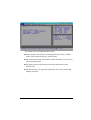
When and How to Use the SCU Program ..............................5-2
When to Use ....................................................................5-2
Starting SCU....................................................................5-2
Moving Around and Making Selections ...........................5-4
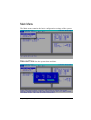
Main Menu ...........................................................................5-5
Advanced Menu....................................................................5-7
Security Menu.......................................................................5-9
Boot Menu..........................................................................5-11
Exit Menu...........................................................................5-13
Chapter 6 Installing Software Drivers ..................................6-1
How to Use the CD ...............................................................6-2
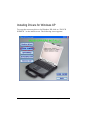
Installing Device Drivers for Windows 2000/Windows XP ...6-3
Install Touch Screen Driver for Windows 2000 .....................6-5
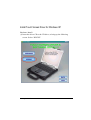
Installing Drivers for Windows XP .......................................6-6
Install Touch Screen Driver for Windows XP........................6-7
Touchscreen Utility.............................................................6-17
Chapter 7 Caring for the Computer ......................................7-1
Protecting the Computer........................................................7-2
Using the Password .........................................................7-2
Using an Anti-Virus Strategy ...........................................7-2
Taking Care of the Computer ................................................7-3
Location Guidelines.........................................................7-3
iv
General Guidelines ..........................................................7-3
Cleaning Guidelines.........................................................7-4
Battery Pack Guidelines...................................................7-4
When Traveling ....................................................................7-5
Chapter 8 Troubleshooting ...................................................8-1
Preliminary Checklist............................................................8-2
Solving Common Problems...................................................8-3
Battery Problems .............................................................8-4
CD/DVD/COMBO Drive Problems (on optional docking
station) ............................................................................8-5
Display Problems.............................................................8-5
Floppy Disk Drive Problems (on optional docking station)8-7
Hardware Device Problems..............................................8-8
Hard Disk Drive Problems...............................................8-8
Keyboard, Mouse, and Touchpad Problems .....................8-9
LAN Problems...............................................................8-10
Wireless LAN Problems ................................................8-10
Modem Problems...........................................................8-11
PC Card Problems .........................................................8-11
Power Management Problems (for Windows) ................8-11
Printer Problems (connected through optional docking
station) ..........................................................................8-12
Software Problems.........................................................8-13
Sound Problems.............................................................8-13
Startup Problems ...........................................................8-14
v
Other Problems..............................................................8-14
Resetting the Computer.......................................................8-15
Appendix A Specifications.................................................. A-1
Preface
This manual contains information that will help you operate the
computer. It is divided into 8 chapters and an appendix.
Chapter 1, Getting Started, takes you through the process of setting up
the computer and identifying its external components.
Chapter 2, Operating Your Computer, tells you how to use the
computer’s components and features.
Chapter 3, Managing Power, provides information on power.
Chapter 4, Expanding Your Computer, provides information on
installing and using peripheral devices.
Chapter 5, SCU (Setup Configuration Utility), describes the SCU
program that configures the computer’s BIOS settings.
Chapter 6, Installing Software Drivers, describes how to install the
drivers and utilities supplied with the computer.
Chapter 7, Caring for the Computer, gives you tips in care and
maintenance.
Chapter 8, Troubleshooting, gives solutions to common problems you
may encounter when using the computer.
Appendix A, Specifications, gives a brief specification of the computer.
vi
Notational Conventions
Throughout this manual, the following conventions are used to
distinguish elements of text.
NOTE: identifies additional information that requires special attention.
CAUTION: identifies important information which, if not followed, may result in loss of data or
damage to the computer.
Keyboard keys are shown in a bold typeset. For example:
Press Enter to complete.
When keys are joined by a plus sign (+), press the first key, and, while
keeping the first key down, press the remaining keys, finally release all
the keys. When necessary, keys are also shown in graphics.
A title, command, setup item, or button that you can see on the screen is
shown in boldface. A value or an option that you can select for a setup
item is shown in italic. For example:
Select Power Management, set it to Enabled, and then
click the OK button.
vii
COMPUTER SOFTWARE COPYRIGHTS
The Motorola products described in this instruction manual
may include copyrighted Motorola computer programs stored
in semiconductor memories or other media. Laws in the United
States and other countries preserve for Motorola certain
exclusive rights for copyrighted computer programs, including
the exclusive right to copy or reproduce in any form the
copyrighted computer program. Accordingly, any copyrighted
Motorola computer programs contained in the Motorola
products described in this instruction manual may not be
copied or reproduced in any manner without the express
written permission of Motorola. Furthermore, the purchase of
Motorola products shall not be deemed to grant either directly
or by implication, estoppel or otherwise, any license under the
copyrights, patents or patent applications of Motorola, except
for the normal non-exclusive, royalty free license to use that
arises by operation of law in the sale of a product.
This Warranty applies within the fifty(50) United States' the
District of Columbia and Canada.
LIMITED WARRANTY
MOTOROLA COMMUNICATION PRODUCTS
If the affected product is being purchased pursuant to a written
Communications System Agreement signed by Motorola, the
warranty contained in that written agreement will apply.
Otherwise, the following warranty applies.
viii
I. WHAT THIS WARRANTY COVERS AND FOR HOW
LONG:
Motorola Inc. or if applicable, Motorola Canada Limited ("Motorola",)
warrants the Motorola manufactured radio communications product,
including original equipment crystal devices and channel elements
("Product"), against material defects in material and workmanship
under normal use and service for a period of Three (3)Years from the
date of shipment.
Motorola, at its option, will at no charge either repair the Product (with
new or reconditioned parts), replace it with the same or equivalent
Product (using new or reconditioned Product), or refund the purchase
price of the product during the warranty period provided purchaser
notifies Motorola according to the terms of this warranty. Repaired or
replaced Product is warranted for the balance of the original applicable
warranty period. All replaced parts of the Product shall become the
property of Motorola.
This express limited warranty is extended by Motorola to the original
end user purchaser purchasing the Product for purposes of leasing or
for commercial, industrial, or governmental use only, and is not
assignable or transferable to any other party. This is the complete
warranty for the Product manufactured by Motorola.
Motorola assumes no obligations or liability for additions or
modifications to this warranty unless made in writing and signed by an
officer of Motorola. Unless made in a separate written agreement
between Motorola and the original end user purchaser, Motorola does
not warrant the installation maintenance or service of the Product.
ix
Motorola cannot be responsible in any way for any ancillary equipment
not furnished by Motorola which is attached to or used in connection
with the product, or for operation of the Product with any ancillary
equipment, and all such equipment is expressly excluded from this
warranty. Because each system which may use the Product is unique,
Motorola disclaims liability for range, coverage, or operation of the
system as a whole under this warranty.
II. GENERAL PROVISIONS:
This warranty sets forth the full extent Motorola’s responsibilities
regarding the product. Repair replacement or Refund of the purchase
price, at Motorola’s option, is the exclusive is the exclusive remedy.
THIS WARRANTY IS GIVEN IN LIEU OF ALL OTHER EXPRESS
WARRANTIES.
MOTOROLA DISCLAIMS ALL OTHER WARRANTIES OR
CONDITIONS, EXPRESS OR IMPLIED INCLUDING THE IMPLIED
WARRANTIES OR CONDITIONS OF MERCHANTABILITY AND
FITNESS FOR A PARTICULAR PURPOSE. IN NO EVENT SHALL
MOTOROLA BE LIABLE FOR DAMAGES IN EXCESS OF THE
PURCHASE OF PRICE THE PRODUCT FOR ANY LOSS OF USE
LOSS OF TIME, INCONVE-NIENCE, COMMERCIAL LOSS, LOST
PROFITS OR SAVINGS OR OTHER INCIDENTAL, SPECIAL
INDIRECT OR CONSEQUENTIAL DAMAGES ARISING OUT OF
THE USE OR INABILITY TO USE SUCH PRODUCT TO THE FULL
EXTENT SUCH MAY BE DISCLAMIED By LAW.
III. How TO GET WARRANTY SERVICE:
Purchaser must notify Motorola’s representative or call Motorola’s
Customer Response Center at1.800.247.2346
within the applicable warranty period for information regarding warranty
service.
x
IV. WHAT THIS WARRANTY DOES NOT COVER:
A) Defects or damage resulting from use of the Product in other than its
normal and customary manner.
B) Defects or damage from misuse, accident, water, or neglect.
C) Defects or damage from improper testing, operation, maintenance,
installation, alteration, modification, or adjustment.
D) Breakage or damage to antennas unless caused directly by defects
in material workmanship.
E) A Product subjected to unauthorized Product modifications,
disassemblies or repairs (including, without limitation, the addition to
the Product of non-Motorola supplied equipment) which adversely affect
performance of the Product or interfere with Motorola’s normal warranty
inspection and testing of the Product to verify any warranty claim.
F) Product which has had the serial number removed or made illegible.
G) Batteries (they carry their own separate limited warranty).
H) Freight costs to the repair depot.
I) A Product which, due to illegal or unauthorized alteration of the
software/firmware in the Product, does not function in accordance
with Motorola’s published specifications or with the FCC type
acceptance labeling in effect for the Product at the time the Product
was initially distributed from Motorola.
J) Scratches or other cosmetic damage to Product surfaces that do not
affect the operation of the Product.
K) That the software in the product will meet the purchaser’s requirements
or that the operation of the software will be uninterrupted or error-free.
L) Normal and customary wear and tear.
M) Non-Motorola manufactured equipment unless bearing a Motorola Part
Number in the form of an alpha numeric number (i.e.,TDE6030B).
xi
V. GOVERNING LAW
In the case of a Product sold in the United States and Canada, this
Warranty is governed by the laws of the State of llli-nois and the
Province of Ontario respectively.
VI. PATENT AND SOFTWARE PROVISIONS:
Motorola will defend, at its own expense, any suit brought against
the end user purchaser to the extent that it is based on a claim that
the Product or its parts infringe a United States patent, and Motorola
will pay those costs and damages finally awarded against the end
user purchaser in any such suit which are attributable to any such
claim, but such defense and payments are conditioned on the
following:
A) That Motorola will be notified promptly in writing by such
purchaser of any notice of such claim;
B) That Motorola will have sole control of the defense of such suit
and all negotiations for its settlement or compromise; and
C) Should the Product or its parts become, or in Motorola’s opinion
be likely to become, the subject of a claim of infringement of a
United States patent, that such purchaser will permit Motorola,
at its option and expense, either to procure for such purchaser the
right to continue using the product or its parts or to replace or
modify the same so that it becomes non-infringing or to grant
such purchaser a credit for the Product or its parts as depredated
and accept its return. The depreciation will be an equal amount
per year over the lifetime of the product or its parts as established
by Motorola.
xii
Motorola will have no liability with respect to any claim of patent
infringement which is based upon the combination of the Product or its
parts furnished hereunder with software, apparatus or devices not
furnished by Motorola, nor will Motorola have any liability for the use
of ancillary equipment or software not furnished by Motorola which is
attached to or used in connection with the Product. The foregoing
states the entire liability of Motorola with respect to infringement of
patents by the Product or any of its parts thereof.
Laws in the United States and other countries preserve for Motorola
certain exclusive rights for copyrighted Motorola software such as the
exclusive rights to reproduce in copies and distribute copies of such
Motorola software. Motorola software may be used only in the Product
in which the software was originally embodied and such software in
such Product may not be replaced, copied, distributed, modified in any
way, or used to produce any derivative thereof. .No other use including,
without limitation, alteration, modification, reproduction, distribution,
or reverse engineering of such Motorola software or exercise of rights
in such Motorola software is permitted. No license is granted by
implication, estoppel otherwise under Motorola patent rights or
copyrights.
EPS-48759-O
FCC INTERFERENCE WARNlNG
The FCC requires that manuals pertaining to Class A and Class B
computing devices must contain warnings about possible interferm1ce
with local residential radio and TV reception. This warning reads as
follows:
xiii
NOTE: This equipment has been tested and found to comply with
limits for a Class B digital device, pursuant to Part 15 of the FCC
Rules. These limits are designed to provide reasonable protection
against harmful interference when the equipment is operated in a
commercial or residential environment. This equipment generates, uses
and can radiate radio frequency energy and, if not installed and used in
accordance with the instruction manual, may cause harmful
interference to radio communications.
Trademarks
Motorola and the Motorola logo are registered trademarks of Motorola
Inc.
Mobile Laptop 850 are trademarks of Motorola.
Microsoft, MS-DOS, MS-Windows, and Windows are registered
trademarks of Microsoft Corporation.
Centrino and Intel are registered trademarks of Intel Corporation.
xiv
CHAPTER 1
Getting Started
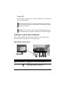
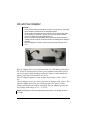
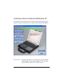
Congratulations on purchasing this industrial notebook computer.
It’s rugged, compact, and portable design allows you to use it in the
field or inside a vehicle and other demanding situations where
conventional notebook computers just cannot measure up. It can also
connect with a docking station to extend the capabilities of input/output
devices.
This chapter first tells you step by step how to get the computer up and
running. You will find instructions for these procedures:
l Unpacking
l Connecting to AC power
l Opening the cover
l Connecting the computer to the docking station
l Turning on the computer
l Turning off the computer
Then, you will find a section briefly introducing the external
components of the computer. And the last section navigates you to the
information you may need after the computer is ready for use.
Getting Started
1-1
Getting the Computer Running
This section guides you through the procedures for getting the
computer ready for operation.
Unpacking
After unpacking the shipping carton, you should find these
standard items:
l Notebook Computer
l Accessories:
− AC adapter (100~240 VAC, 50~60 Hz)
− AC power cord
− Driver CD
− Docking Station (Optional), include CD-ROM/DVDROM/COMBO & FD Drive
− Car-mount (Optional)
− Car adapter (12~32 VDC) − (Optional)
− External battery charger − (Optional)
− This Operation Manual
− Touchscreen Pen (Optional)
− 3M High Performance Cloth
Inspect all the items. If any item is damaged or missing, notify
your dealer immediately.
Keep the shipping carton and packing materials in case you need
to ship or store the computer in the future.
Connecting to AC Power
The computer operates either on the external AC power or internal
battery power. It is suggested that you use AC power when you
start up the computer for the first time.
CAUTION: Use only the AC adapter included with your computer. Using other AC
adapters may damage the computer.
1-2
Getting Started
1. Make sure the computer is turned off.
2. Plug the DC cord of the AC adapter to the power connector on the
computer.
NOTE: When the computer is attached to the docking station, connect the DC cord to
the power connector on the docking station instead.
3. Plug the female end of the AC power cord to the AC adapter and the
male end to an electrical outlet.
4. When the AC adapter is connected, the indicator on the computer /
docking station lights up, indicating that power is being supplied from
the electrical outlet to the AC adapter and onto your computer /
docking station. Now, you are ready to turn on the computer.
CAUTION:
l When you disconnect the AC adapter, disconnect from the electrical outlet first and
then from the computer / docking station. A reverse procedure may damage the
AC adapter or the computer / docking station.
l When unplugging the connector, always hold the plug head. Never pull on the
cord.
NOTE: When the AC adapter is connected, it also charges the battery pack. For
information on using battery power, see Chapter 3.
Opening the Cover
CAUTION: Be gentle when opening and closing the cover. Opening it vigorously or
slamming it shut could damage the computer.
Open the top cover by pulling the cover latch (bottom part)
outward using your thumb and at the same time using your index
finger to press on the notch on the top portion, and lifting up the
cover. You can tilt the cover forward or backward for optimal
viewing clarity.
Getting Started
1-3
Closing the Cover
When closing the cover, make sure that the hook is latched properly to
safeguard against the following:
z To prevent damage to the LCD screen during transport.
z To prevent the computer from accidentally waking up from Suspend mode during
transport without the user’s knowledge.
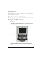
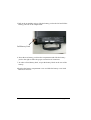
Turning On and Off the Computer
Turning On
1. Make sure the computer / docking station is connected to AC power.
2. Press the power button.
Power
3. Each time the computer is turned on, it performs a Power-On Self test (POST), and the operating system such as Windows should
start.
1-4
Getting Started
Turning Off
To turn off the computer power, use the “Shut Down” command of
your operating system.
NOTE: There are other ways you can stop the computer so that you will be back to
where you left off when you next turn on the computer. (See “Stopping the Computer”
in Chapter 2 for information.)
CAUTION: If you have to turn the computer on again immediately after turning it off,
wait for at least five seconds. Turning the computer off and on rapidly can damage it.
Taking a Look at the Computer
This section identifies the external components of the computer and
briefly describes the function of each component.
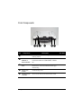
Right-Side Components
Ref
n
Component
Device Indicators
See Also
Shows the current status of the computer’s
devices.
Battery State Indicator – blinks orange
when battery charge is 9% or lower.
Getting Started
1-5
Ref
Component
Description
See Also
Battery Charge Indicator:
– glows green when the battery is fully
charged.
– Glows orange when the battery is being
charged.
– Is dark when battery has no charge left
and AC adapter is connected and
powered on.
System State Indicator:
– glows green when the computer is
powered on.
– Glows orange when the computer is in
Suspend mode.
AC Power Indicator – glows green when
computer is connected to AC power and is
powered-on.
•
PC Card Slot
Accepts a PC Card for additional
functions.
Ž
RJ-45 Connector
Connects the LAN cable.
•
RJ-11 Connector
Connects the telephone line.
•
USB Port
Connects an USB device such as printer,
digital camera, joystick and more.
1-6
Getting Started
Left-Side Components
Ref
Component
n
Audio Output
Connector
Connects a hi-fi set, radio set, synthesizer,
walkman, etc.
o
Microphone In
Connector
Connects an external microphone.
Getting Started
Description
See Also
1-7
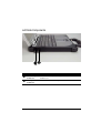
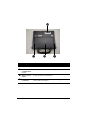
Rear Components
Ref
Component
Description
n
USB Port
Each of the two ports connects a USB device,
such as a USB floppy drive, printer, digital
camera, joystick, and more.
o
VGA Port
Connects an external monitor.
p
Serial Port
Connects a serial device, such as mouse.
q
Power
Connector
Connects the AC adapter.
1-8
See Also
Getting Started
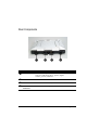
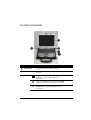
Front Components
Ref
Component
Description
Œ
Notched Hole
Allows you to hook the computer to the
docking station.
•
Wireless
Modem or
GSM Antenna
Serves as the antenna for the optional
wireless modem or GSM/GPRS, CDMA
etc..
Ž
Touchscreen
Pen
Provides a convenient way to use the
touchscreen. Can be stretched for better grip
and handing.
•
Top Cover
Latch
Locks the top cover.
•
Wireless LAN
Antenna
Serves as the antenna for the Wireless LAN.
Getting Started
See Also
1-9
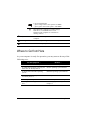
Ref
Component
Description
See Also
n
Speaker
Sends out sound and voice from the computer.
o
Battery
Compartment
Cover
Open the cover to access the battery pack.
p
Battery Cover
Latch
Locks the battery compartment.
q
Docking
Connector
Serves as the interface between the docking
station and the computer.
1-10
Getting Started
Top-Open Components
Ref
Component
Description
n
LCD Screen
o
Device Indicators Shows the current status of the computer’s
devices.
See Also
Displays the output of the computer.
Caps Lock Indicator – glows green when Caps
Lock key is pressed and its function is
activated.
Num Lock Indicator– glows green when Num
Lk key is pressed and its function is activated.
Scroll Lock Indicator – glows green when
Scroll Lk key is pressed and its function is
activated.
Getting Started
1-11
LAN 10/100 Indicator
– glows orange when LAN speed is 10 MBPS
– glows green when LAN speed is 100 MBPS
Hard Disk Drive Indicator (includes Floppy
Disk Drive or CD-ROM Drive In-use
Indicator when computer is connected to
docking station)
Ž
Keyboard
Serves as the data input device of the
computer.
•
Touchpad
Serves as the pointing device of the computer.
•
Power Button
Turns the computer power ON and OFF.
Where to Go from Here
As your computer is ready for operation, you may want to do any of the
following now:
For this purpose …
Do this …
To know more about the computer …
Go on to the next chapter.
To install the operating system if your
dealer has not already done so …
See the operating system manual.
To know more about the operating
system …
Read the operating system manual.
To install the drivers if your dealer has See Chapter 6.
not already done so …
To set a power-on password …
See “Security Menu” in Chapter 5.
To charge the battery pack for the first See “Charging the Battery Pack” in
time …
Chapter 3.
1-12
Getting Started
CHAPTER 2
Operating Your Computer
This chapter provides information about the use of the computer.
If you are new to computers, reading this chapter will help you learn the
operating basics. If you are already a computer user but are new to
notebook computers, you may choose to read only the parts containing
information unique to your computer.
Described in this chapter are the operating basics of these components:
l Keyboard
l Touchpad
l Touchscreen
l Floppy disk drive (when connected to docking station)
l Hard disk drive
l CD/DVD/COMBO drive (when connected to docking station)
And these features:
l Starting and stopping the computer
l Function keys
l Video features
l Audio features
l Communication features
Operating Your Computer
2-1
Starting and Stopping the Computer
There are a number of ways to start and stop the computer.
Starting the Computer
You always start the computer using the power button.
A computer starts up with an operating system (OS) existing on the
storage device such as the hard disk; or from a floppy disk or CD if you
have the docking station installed. The computer will automatically load
the OS after you turn it on. This process is called booting.
NOTE: An operating system is the platform for all your software application programs
to run on. The most widely used operating system today is Microsoft Windows.
Stopping the Computer
When you finish a working session, you can stop the computer by
turning off power or leaving the computer in Standby or Suspend mode:
To stop in
this mode …
Off
Do this …
To start up or
resume again
Follow the shutdown procedure of your
operating system. This can prevent loss
of unsaved data or damage to your
software programs.
Press the power
button.
If the system is locked up because of
hardware or software problems, press the
power button to turn off the computer.
Standby
Depending on your settings in Windows,
you can place the computer in Standby
mode by:
•
•
•
2-2
Press any key or
Open Lid.
Closing the display cover
Pressing the power button
Pressing Fn+F10
Operating Your Computer
To stop in
this mode …
Do this …
To start up or
resume again
Hibernation
Depending on your settings in Windows,
you can place the computer in
Hibernation mode:
l by pressing the power button
l by closing the display cover.
Press the power
button.
If you choose to stop in Standby or Hibernation mode, you can
return to where you left off the next time you start up the
computer. (See “Power Management” in Chapter 3 for more
information.)
Operating Your Computer
2-3
Using the Keyboard
Your keyboard has all the standard functions of a full-sized computer
keyboard plus a Fn. key added for specific functions.
The standard functions of the keyboard can be further divided into four
major categories:
Typewriter keys
Cursor-control keys
Numeric keys
Function keys
Typewriter Keys
Typewriter keys are similar to the keys on a typewriter. Several keys are
added such as the Ctrl, Alt, Esc, and lock keys for special purposes. The
Control key is normally used in combination with other keys for
program-specific functions. The Alternate key is normally used in
combination with other keys for program-specific functions. The Escape
key is usually used for stopping a process. Examples are exiting a
program and canceling a command. The function depends on the
program you are using. When the lock keys (Caps Lock , Num Lk, and Scroll
Lk) are pressed, their corresponding indicators light up on the
computer’s device indicators.
Cursor-Control Keys
NOTE: The word “cursor” refers to the indicator on the screen that lets you know
exactly where on your screen anything you type will appear. It can take the form of a
vertical or horizontal line, a block, or one of many other shapes.
2-4
Operating Your Computer
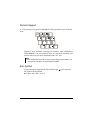
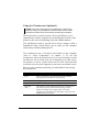
Numeric Keypad
A 15-key numeric keypad is embedded in the typewriter keys as shown
next:
Numeric keys facilitate entering of numbers and calculations.
When Num Lk is on, the numeric keys are activated; meaning you
can use these keys to enter numerals with “Fn” key.
NOTE:
Some software may not be able to use the numeric keypad on the computer. If so,
use the numeric keypad on an external keyboard instead.
l
Euro Symbol
If your Windows supports the Euro dollar sign
the sign on the keyboard.
, you can press
l To press the CTRL+ALT+E.
Operating Your Computer
2-5
Function Keys
On the top row of the keys are the function keys: F1 to F12. Function
keys are multi-purpose keys that perform functions defined by
individual programs.
Hot key functions are assigned to F1, F3 , F4, F5, F6, F8, F9, and F10 by your
computer. (See “Hot Keys” section in this chapter for information.)
Fn. Key
The Fn. key, at the lower left corner of the keyboard, is used with
another key to perform the alternative function of a key. The letter “Fn.”
and the alternative functions are identified by the color of blue on the
keycap. To perform a desired function, first press and hold Fn., then
press the other key.
Hot Keys
Key
2-6
Description
Fn+F1
Toggles Keyboard backlight.
Fn+F3
Decreases the speaker volume.
Fn+F4
Increases the speaker volume.
Fn+F5
Decreases the LCD brightness.
Fn+F6
Increases the LCD brightness.
Fn+F7
Toggle LCD Backlight On/Off.
Fn+F8
Switches LCD on and off.
Operating Your Computer
Key
Description
Fn+F9
Switches the display output to one of the following three when
an external CRT monitor is connected through the docking
station.
LCD
CRT monitor
Display on both
NOTE: If the display mode is set to 256 colors or lower, or in
DOS mode, there will be only two modes for selecting: CRT
only and Display on both.
Fn+F10
Serves as the sleep button that you can define with Windows’
Power Management. (See “Power Management” in chapter
3.)
Operating Your Computer
2-7
Using the Touchpad
CAUTION: Do not use a sharp object such as a pen on the touchpad. Doing so may
damage the touchpad surface.
NOTE: For optimal performance of the touchpad, keep your fingers and the pads
clean and dry. When tapping on the pad, tap lightly. Do not use excessive force.
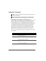
The touchpad is a pointing device that allows you to
communicate with the computer by controlling the location of the
pointer on the screen and making selection with the buttons.
The touchpad consists of a rectangular pad and two buttons. To
use the touchpad, place your forefinger or thumb on the pad. The
rectangular pad acts like a miniature duplicate of your display.
As you slide your fingertip across the pad, the pointer (also
called cursor) on the screen moves accordingly. When your
finger reaches the edge of the pad, simply relocate yourself by
lifting the finger and placing it on the other side of the pad.
Here are some common terms that you should know when using
the touchpad:
Term
Action
Point
Move your finger on the pad until the cursor points to the
selection on the screen.
Click
Press and release the left button.
-orTap gently anywhere on the pad.
Double-click
Press and release the left button twice in quick succession.
-orTap twice on the pad rapidly.
2-8
Operating Your Computer
Term
Drag and
drop
Action
Press and hold the left button, then move your fingers
until you reach your destination (drag). Finally, release
the button (drop) when you finish dragging your selection
to the destination. The object will drop into the new
location.
-orGently tap twice on the pad, and on the second tap, keep
your finger in contact with the pad. Then, move your
finger across the pad to drag the selected object to your
destination. When you lift your finger from the pad, the
selected object will drop into place.
Scroll
To scroll is to move up and down or left and right in the
working area on the screen.
To move vertically, place your finger on the right edge of
the pad and slide your finger up and down along the edge.
To move horizontally, place your finger on the bottom
edge of the pad and slide your finger left and right.
This function works only after you install the touchpad
driver supplied with the computer and it may not work for
all applications.
TABLE NOTE: If you swap the left and right buttons, “tapping” on the
touchpad as an alternative method of pressing the left button will no longer be
valid.
Configuring the Touchpad
You may want to configure the touchpad to suit your needs. For
example, if you are a left-handed user, you can swap the two
buttons so that you can use the right button as the left button and
vise versa. You can also change the size of the on-screen pointer,
the speed of the pointer, and so on.
To configure the touchpad, you can use the standard Microsoft or
IBM PS/2 driver if you are using Windows. However, you can
install the touchpad driver supplied with your computer to take
advantage of more powerful features. (For information on
installing the driver, see “How to Use the CD” in Chapter 6.)
Operating Your Computer
2-9
Using the Touchscreen (Optional)
CAUTION: Do not use a sharp object such as a ballpoint pen or pencil on the
touchscreen. Doing so may damage the touchscreen surface. Use the included
touchscreen pen instead, which can be stretched for better grip and handling.
The touchscreen is a touch-sensitive device that allows you to
communicate with the computer by controlling the location of the
pointer on the screen and making selection with the buttons.
The touchscreen needs a special device driver support called a
PenMount Utility, which allows you to easily use the computer
without any external pointing device.
The touchscreen pen is located at the handle of the computer
(refer to “Rear Components” on chapter 1). To use the
touchscreen, place the touchscreen pen or your forefinger on the
touchscreen. As you slide your pen or fingertip across the screen,
the pointer, or cursor, on the screen moves in the same direction
across the screen as your fingertip or pen moves across the screen.
Here are some common terms that you should know when using
the touchscreen:
Term
2-10
Action
Point
Move your finger or pen on the touchscreen until the
cursor points to the selection on the screen.
Click
Tap gently anywhere on the touchscreen.
Double-click
Tap twice on the touchscreen rapidly.
Drag and
drop
Press lightly on the touchscreen and move your finger or
pen until you reach your destination (drag). Finally,
release your finger or pen (drop) when you finish
dragging your selection to the destination. The object will
drop into the new location.
Operating Your Computer
Term
Scroll
Action
To scroll is to move up and down or left and right in the
working area on the screen.
To move vertically, place your finger or pen on the right
edge of the touchscreen and slide your finger or pen up
and down along the edge. To move horizontally, place
your finger or pen on the bottom edge of the touchscreen
and slide your finger or pen left and right.
This function works only after you install the touchscreen
driver supplied with the computer and it may not work for
all applications.
TABLE NOTE: If you swap the left and right buttons, “tapping” on the
touchscreen as an alternative method of pressing the left mouse button will no
longer be valid.
Configuring the Touchscreen
You may want to configure the touchscreen to suit your needs. You can
also change the size of the on-screen pointer, the speed of the pointer,
and so on.
To configure the touchscreen, you can use the standard Microsoft or
IBM PS/2 driver if you are using Windows. However, you can install
the touchscreen driver supplied with your computer to take advantage of
more powerful features. (For information on installing the driver, see
Chapter 6.)
Operating Your Computer
2-11
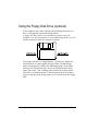
Using the Floppy Disk Drive (optional)
Your computer may come with the optional floppy disk drive as
drive A through the optional docking station.
A floppy disk drive allows you to install new programs into your
computer, or to store information on a removable floppy disk so you can
transfer information from one computer to another.
The floppy disk drive is a high-density 3.5-inch one, which can
read and write to either double-density (2DD) 720-KB floppy
disks or high-density (2HD) 1.44-MB floppy disks. Notice that
both types of floppy disk have an arrow imprinted on the front
upper left corner , and a sliding write-protect tab on the bottom
left corner, as illustrated above. When opened, the write-protect
tab prevents data from being written to, or erased from, the floppy
disk.
2-12
Operating Your Computer
Inserting and Ejecting Floppy Disks
To insert a floppy disk, hold it with the arrow facing up and
towards the drive. Slide the disk into the drive until it clicks into
place.
To eject a floppy disk, first ensure that the floppy disk drive in-use
indicator is off, and then press the eject button on the drive. When
the floppy disk pops out of the drive, remove the floppy disk and
store it properly.
CAUTION:
l Never turn off or reset the computer while the floppy disk drive in-use indicator is
on.
l Always store your floppy disks in a safe, clean container, to protect them from the
environment and magnetic fields.
l A floppy disk must be formatted before you can use it. (To know how to format a
floppy disk, see your operating system manual.)
Operating Your Computer
2-13
Using the Hard Disk Drive
Your computer comes with a hard disk drive as drive C.
A hard disk drive is a storage device with non-removable, rotating,
magnetic storage platters inside it. It is where your operating system and
application software programs are stored.
Your hard disk drive is a 2.5-inch IDE (Integrated Drive Electronics)
hard disk drive. This type of drive embodies the latest in fast, reliable
mass storage by integrating all the control circuitry necessary for
operation directly onto the drive itself. This allows the drive
manufacturer to carefully optimize drive performance.
CAUTION:
Make regular backups of your data files from your hard disk drive to floppy disks or
other storage media.
l Never try to remove or install the hard disk drive while the computer is powered
on. Doing so can result in loss of data, and can damage the computer and the
hard disk drive’s sensitive circuitry.
l Never turn off or reset the computer while the hard disk drive in-use indicator is on.
l
2-14
Operating Your Computer
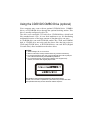
Using the CD/DVD/COMBO Drive (optional)
Your computer may come with an optional CD-ROM drive, COMBO
drives, or DVD-ROM drives through the optional docking station. This
drive is usually configured as drive D.
The drive uses removable 5.25-inch silver CD-ROM discs, which look
like standard music CDs. It is an ideal medium to use for distributing
multimedia because of the huge amount of data that a disc can store.
A CD-ROM drive can read CD-ROMs, audio CDs, CD-R, and COMBO
disk. A CD-RW drive not only reads the above discs but also writes to
CD-R and CD-RW discs. A DVD-ROM drive can read DVD (Digital
Versatile Disc) discs in addition to the above discs.
CAUTION:
1. When inserting a CD, do not use force.
2. Make sure the CD is correctly inserted into the tray, and then close the tray.
3. Do not leave the CD tray open. Also, avoid touching the lens in the tray with your
hand. If the lens becomes dirty, the CD-ROM may malfunction.
4. Do not wipe the lens with rough surface materials (such as paper towel).
Instead, use a cotton swab to gently wipe the lens.
FDA regulations require the following statement for all laser-based devices:
“Caution, Use of controls or adjustments or performance of procedures other than
those specified herein may result in hazardous radiation exposure.”
Operating Your Computer
2-15
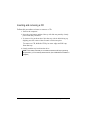
Inserting and removing a CD
Follow this procedure to insert or remove a CD.
1. Turn on the computer.
2. Press the eject button and the CD tray will slide out partially. Gently
pull it until fully extended.
3. To insert a CD, put down the CD in the tray with its label facing up.
Slightly press the center of the CD until it clicks into place.
To remove a CD, hold the CD by its outer edge and lift it up
from the tray.
4. Gently push the tray back into the drive.
NOTE: In the unlikely event that you are unable to release the CD tray by pressing
the eject button, you can manually release the CD. (See “CD/DVD Drive Problems” in
Chapter 8.)
2-16
Operating Your Computer
Using the Video Features
The video subsystem of your computer features:
l 12.1-inch TFT (Thin-Film Transistor) color LCD display with
1024x768 XGA (Extended Video Graphics Array) resolution.
l Sunlight Readable Panel , Hi-Contrast solution LCD (Optional).
l Simultaneous display on LCD and external monitor (connect through
the docking station), which is useful when you have a presentation as
you can control the screen from your computer and face the audience
at the same time.
l Multi-display capability, which allows you to expand your desktop on
the screen to another display device so that you have more desktop
space to work on.
Power Management.
NOTE: The computer enters Standby or Suspend mode when the LCD is closed. If
you want to use the computer with the LCD closed, set None to the “When I close the
lid of my portable computer” option in the Power Management properties. Thus the
computer does not enter Standby or Suspend mode when the LCD is closed.
Configuring the Display Modes
NOTE: To take advantage of the enhanced video capabilities, the video driver
supplied with your computer must be installed.
Your computer has been set to a default resolution and number of colors
before shipment. You can view and change display settings through
your operating system. See your operating system documentation or
online help for specific information.
For displaying in higher resolutions, you can connect an external CRT
monitor that supports higher resolutions through the optional docking
station. (See“Connecting a Monitor”in Chapter 4 for more information.)
The following table lists the display modes supported by your computer.
Operating Your Computer
2-17
Display Mode
Resolution
640x480
720x480
800x600
848x480
2-18
LCD Only CRT Only
Simultaneous
Display
Colors
8-bit
√
√
√
16-bit
√
√
√
24-bit
√
√
√
32-bit
√
√
√
8-bit
√
√
√
16-bit
√
√
√
24-bit
√
√
√
32-bit
√
√
√
8-bit
√
√
√
16-bit
√
√
√
24-bit
√
√
√
32-bit
√
√
√
8-bit
√
√
√
16-bit
√
√
√
24-bit
√
√
√
32-bit
√
√
√
Operating Your Computer
LCD Only
CRT Only
Simultaneous
Display
8-bit
√
√
√
16-bit
√
√
√
24-bit
√
√
√
32-bit
√
√
√
Display Mode
1024x768
1152x864
1280x1024
1600x1200
8-bit
√
16-bit
√
24-bit
√
32-bit
√
8-bit
√
16-bit
√
24-bit
√
8-bit
√
16-bit
√
TABLE NOTE: 8-bit = 256 colors; 16-bit = High Color or 65,536 (64 K)
colors; 24 and 32-bit = True Color 16,770,000 (16 M) colors.
Operating Your Computer
2-19
Using the Audio Features
NOTE:
To take advantage of the enhanced audio capabilities, the audio driver supplied
with your computer must be installed.
l If you experience interference while recording, try lowering the microphone
recording volume.
l
The audio subsystem of your computer features:
l Digital audio and analog mixing functions required for recording and
playing sound on your computer
l SoundBlaster Pro, Adlib, and Microsoft Windows Sound System
support
l Speaker (located on the underside of both computer and the optional
docking station)
l External audio connectors (located on the left side of the computer or
on the right side of the optional docking station)
Ways of playing and recording sound vary with the operating
system used. See your operating system documentation or online
help for specific information.
Connecting Audio Devices
For higher audio quality, you can send or receive sound through
external audio devices.
l Microphone Connector (
) can be connected to an external
microphone for recording voice or sound.
l Audio Output Connector (
) can be connected to the line-in
connector of powered speakers with built-in amplifiers, headphones,
or earphone set.
NOTE: When using external speakers/headphones, you cannot use the internal one.
2-20
Operating Your Computer
Using the Communication Features
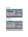
Using the Modem
NOTE: To take advantage of the modem feature, the modem driver supplied with
your computer must be installed.
The internal 56 K fax/data modem allows you to use the telephone line
to communicate with others by fax, email, or connect to an online
service or bulletin board.
To connect the telephone line to the modem, connect the end nearest the
core on the modem cable to the computer’s RJ-11 connector and the
other end to the telephone line.
Using the LAN
NOTE for Windows 2000: To take advantage of the LAN feature, the LAN driver
supplied with your computer must be installed.
The internal 100Base-T LAN (Local Area Network) module allows you
to connect your computer to a network. It supports data transfer rate up
to 100 Mbps.
To connect the network cable to the LAN module, connect one end of
the LAN cable to the RJ-45 connector on the computer and the other
end to the network hub.
Operating Your Computer
2-21
Using the Wireless LAN
Depending on your model, an internal Mini PCI wireless LAN (WLAN) card may
have been pre-installed by your computer manufacturer at the factory. This card
allows you to access corporate networks or the Internet in a wireless environment.
The WLAN features include:
IEEE 802.11b standard compliance
2.4 GHz DSSS (Direct Sequence Spread Spectrum) technology
Peer-to-Peer (Ad-Hoc) and Access Point (Infrastructure) modes support
WEP (Wired Equivalent Privacy) 64/128-bit data encryption
Transmission rate at 11 Mbps, 5.5 Mbps, 2 Mbps, and 1 Mbps with automatic data
rating
To take advantage of the WLAN feature, make sure that the WLAN driver is installed
correctly. (See Chapter 6 for more information.) If your WLAN card was provided by
your dealer instead of the computer manufacturer, contact your dealer for the correct
driver to use.
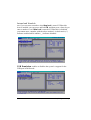
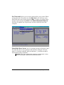
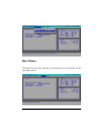
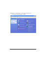
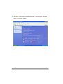
Configuring the WLAN
After driver installation, you can use the WLAN utility to configure and monitor your
WLAN connection. If you are using Windows XP, you can also use its built-in
WLAN utility. Follow this procedure to launch the WLAN utility in Windows XP:
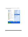
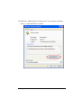
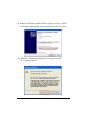
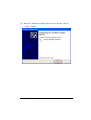
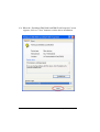
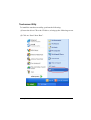
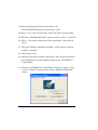
1. Select Control Panel from the Start menu.
2. Click Network and Internet Connections.
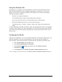
3. Click Network Connections, then double-click the Wireless Network
Connection icon
.
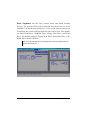
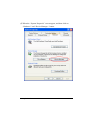
4. Click Properties in the Wireless Network Connection Status dialog box.
You can configure your WLAN settings in the Wireless Network Connection Properties dialog box.
2-22
Operating Your Computer
CHAPTER 3
Managing Power
Your computer operates either on external AC power, car adapter, or
internal battery power.
This chapter tells you how you can effectively manage power. To
maintain optimal battery performance, it is important that you use the
battery in the proper way.
The topics in this chapter include:
What is an AC or car adapter?
How to charge the battery pack
When and how to initialize the battery pack
How to check the battery level
How to replace the battery pack
What happens when the battery is low and what actions to take
What is Power Management?
How to save power
Managing Power
3-1
AC and Car Adapter
CAUTION:
z The AC and car adapter is designed for use with your computer only. Connecting
the AC adapter to another device can damage the adapter.
z The AC power cord supplied with your computer is for use in the country where
you purchased your computer. If you plan to go overseas with the computer,
consult your dealer for the appropriate power cord.
z When you disconnect the AC adapter, disconnect from the electrical outlet first
and then from the computer. A reverse procedure may damage the AC adapter or
computer.
z When unplugging the connector, always hold the plug head. Never pull on the
cord.
The AC adapter serves as a converter from AC (Alternating Current) to
DC (Direct Current) power because your computer runs on DC power,
but an electrical outlet usually provides AC power. It also charges the
battery pack when connected to AC power.
The AC adapter operates on any voltage in the range of 100 ~ 240 V
AC.
The car adapter serves as a converter from car battery to DC power. The
cigarette lighter port of the car usually provides DC power. It also
charges the battery pack when connected. The car adapter operates on
any voltage in the range of 12 ~ 32 V DC.
NOTE: The battery pack cannot be charged when the input power of car adapter falls below
11.5 V DC.
3-2
Managing Power
Battery Pack
The battery pack is the internal power source for the computer. It is
rechargeable using the AC or car adapter.
The operating time of a fully charged battery pack depends on how you
are using the computer. When your applications often access peripherals,
you will experience a shorter operating time.
NOTE: Care and maintenance information for the battery is provided in Chapter 8. In
addition to this chapter, be sure to read the “Battery Pack Guidelines” section in
Chapter 8 as well.
Charging the Battery Pack
NOTE:
l
l
l
Charging will not start if the battery’s temperature is below 0°C (32°F) or above
40°C (104°F).
The charging process will stop when the battery’s temperature gets above 60°C
(140°F). If this happens, the battery pack may be damaged, please contact your
dealer.
During charging, do not disconnect the AC adapter before the battery has been
fully charged; otherwise you will get a prematurely charged battery.
To charge the battery pack, connect the AC adapter to the computer and
an electrical outlet. The Battery Charge Indicator LED on the computer
glows orange to indicate that charging is in progress. You are advised to
keep the computer power off while the battery is being charged. When
the battery is fully charged, the Battery Charge Indicator LED glows
green.
It takes approximately 90 minutes to charge the battery pack to 80%
capacity and two or three more hours to fully charge the battery pack.
CAUTION: After the computer has been fully recharged, do not immediately
disconnect and reconnect the AC adapter to charge it again. Doing so may damage
the battery.
Managing Power
3-3
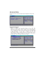
Initializing the Battery Pack
You need to initialize a new battery pack before using it for the first
time or when the actual operating time of a battery pack is much less
than expected.
Initializing is the process of fully charging, discharging, and then
charging. It can take several hours.
1. Make sure the computer power is turned off. Connect the AC adapter to fully
charge the battery pack.
2. After the battery pack is fully charged, turn on the computer.
3. Disconnect the AC adapter and leave the computer on until the battery is
fully discharged. The computer will shut down automatically.
4. Connect the AC adapter to fully charge the battery pack.
Checking the Battery Level
NOTE: Any battery level indication is an estimated result. The actual operating time
can be different from the estimated time, depending on how you are using the
computer.
You can check the approximate battery level using the battery meter
function of the operating system. To read the battery level in Windows,
on the taskbar. (Click the
click the icon
is using AC power.)
icon if the computer
Replacing the Battery Pack
CAUTION:
l There is danger of explosion if the battery is incorrectly replaced. Replace the
battery only with the computer manufacturer’s optional battery packs. Discard
used batteries according to the dealer’s instructions.
l Do not attempt to disassemble the battery pack.
3-4
Managing Power
If you often rely on battery power for a long period of time while
traveling, you may consider the purchase of an additional battery pack
from your dealer and keep it with you in a fully charged state as a
backup.
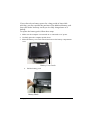
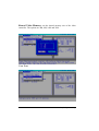
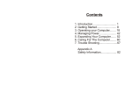
To replace the battery pack, follow these steps:
1. Make sure the computer is not turned on or connected to AC power.
2. Carefully place the computer upside down.
3. Slides the battery cover latch inward and remove the battery compartment
cover.
Battery Cover Latch
4. Pull the battery pack.
Battery Block
Managing Power
3-5
5. Pull on the protruding strip to slide the battery pack to the left and lift the
battery pack out of its compartment.
Pull Battery Pack
6. Insert the new battery pack into the compartment and slide the battery
pack to the right to allow the proper connection of connectors.
7. In order to fixed battery back, we put the battery block on the rear of the
battery.
8.Replace the battery compartment cover and slide the battery cover latch
outward to secure it.
3-6
Managing Power
Battery Low Signals and Actions
Battery Low occurs when the battery has approximately 10% of its
charge remaining. The computer in the Battery State Indicator LED
blink to alert you to take actions.
NOTE: You can set up your threshold and signals of Battery Low under Windows.
Immediately save your data upon Battery Low. The remaining operating
time depends on how you are using the computer. If you are using the
audio subsystem, PC Card, hard or CD-ROM or floppy disk drives, the
battery might run out of charge very quickly.
Always respond to Battery Low by placing your computer on suspendto-disk, turning off the computer, or connecting the AC or car adapter.
If you do not take any action and after two minutes’, the computer will
automatically suspend-to-disk (if enabled under O/S program) and turn
off or, system will continue on until battery is dead.
l
l
l
CAUTION:
If you are using a flash PC Card, do not access the card during battery low
periods. This is because the access may take longer than the time it takes the
battery to run out of charge, thus making your access to the card unsuccessful.
If you fail to save your data when the battery completely runs out of charge, then
you lose your data.
Managing Power
3-7
Power Management
Your computer supports APM (Advanced Power Management) and
ACPI (Advanced Configuration and Power Interface) for power
management. The power management feature allows you to reduce the
power consumption for energy saving.
With an ACPI-compliant operating system such as Windows 98 and
Windows 2000, power supply to different computer components is
controlled on an as-needed basis. This allows maximum power
conservation and performance at the same time.
In general, Windows’ power management works in this way:
What …
When …
Power to the hard disk is turned off
When the hard disk has been idle for
a set period.
Power to the display is turned off
When the display has been idle for a
set period.
The computer enters Standby mode.
The hard disk and display are turned
off and the entire system consumes
less power.
When the entire system has been idle
for a set period, or
when you press Fn+F10, * or
when you close the cover, * or
when you press the power button. *
The computer enters Hibernation
mode. (See the next subsection for
more information.)
When you press Fn+F10, * or
when you close the cover, * or
when you press the power button. *
* Depends on your settings in Windows.
For detailed information on power management, see Windows’ Help.
Suspend-to-Disk (Suspend mode)
NOTE: If your operating system does not support ACPI, you can use the computer’s
“Suspend-to-Disk” function, which is equivalent to Windows’ Hibernation function.
(See “Power Menu” in Chapter 5 for more information.)
3-8
Managing Power
Manual Power Management
You can manually initiate Suspend-to-disk mode at any time in one of
two ways:
l Use the O/S that supports the Suspend function.
l Press down the power button and release it in less than 4 seconds with the
system on. Repeat the action to wake up the system under Suspend mode.
Suspend-to-disk is a very useful feature. People frequently open many
applications when they use computers. It takes some time to get all
these applications open and running, and normally they all have to be
closed before the system can be turned off.
When you use the Suspend-to-disk feature, you do not have to close the
applications. The computer stores the state of your computer to a file on
the hard disk and then shut down. The next time you turn on your
computer, you return to exactly where you left off.
Managing Power
3-9
Power-Saving Tips
In addition to your computer’s automatic power management, you can
do your part to maximize the battery’s operating time by following
these suggestions.
l Do not disable Power Management.
l Decrease the LCD brightness to the lowest comfortable level.
l Disable the parallel and serial ports if no devices are connected to these
ports. (See “Advanced Menu” in Chapter 5.)
l If you work with an application that uses the serial port or a PC Card, exit
the application when you finish using it.
l If you have a PC Card installed, remove it when not in use. Some PC Cards
drain power even while they are inactive.
l Turn off the computer when you are not using it.
3-10
Managing Power
CHAPTER 4
Expanding Your Computer
You can expand the capabilities of your computer by connecting other
peripheral devices. When using a device, be sure to read the
instructions accompanying the device together with the relevant
section in this chapter.
This chapter gives guidelines on installing and using these devices:
External monitor
Parallel device (through the optional docking station)
Serial device
USB device
PC Card
Expanding Your Computer
4-1
Connecting an External Monitor (Optional)
If you want the benefits of a larger display screen with higher
resolution, you can connect an external CRT monitor to your
computer through the optional docking station.
Follow this procedure to connect an external monitor:
1. Make sure the computer is not turned on.
2. Plug the monitor’s D-type signal connector to the docking station’s
VGA port.
3. Plug one end of the monitor’s power cord into the power socket on
the monitor and the other end to an electrical outlet.
4. To use the monitor, turn on the monitor before turning on the
computer.
5. The monitor should respond by default. If not, you can switch the
display to the monitor or to both (simultaneous displays) by pressing
Fn+F9. In Windows, you can also change the display through the
settings in Display Properties.
6. You can change display settings through your operating system. See
your operating system documentation or online help for specific
information.
CAUTION: Do not disconnect the external monitor while the computer is in Standby mode
or Suspend mode. If no external monitor is connected when the computer resumes, the
LCD remains blank and the output is not displayed.
4-2
Expanding Your Computer
Connecting a Parallel Device (optional)
The optional docking station has a p arallel port for connecting a
parallel device such as printer. The port supports ECP (Extended
Capabilities Port) and EPP (Enhanced Parallel Port) modes that turn
the standard parallel port into a high-speed bi-directional peripheral
port.
Follow this procedure to connect a parallel device:
1. Make sure that the “LPT Port” item is set properly in the BIOS Setup
program. (See “Advanced Menu” in Chapter 5 for information.)
2. Make sure the computer is not turned on.
3. Plug the parallel device’s cable to the docking station’s parallel port.
4. If the parallel device has independent power, plug its power cord into
an electrical outlet.
5. If the parallel device has its own power switch, turn on the parallel
device before turning on the computer.
Expanding Your Computer
4-3
Connecting a Serial Device
Your computer has a serial port for connecting a serial device such as
a serial mouse or modem.
Follow this procedure to connect a serial device:
1. Make sure the “COM1 Port” item is set properly in the SCU program.
(See “Advanced Menu” in Chapter 5 for information.)
2. Make sure the computer is not turned on.
3. Plug the device cable to the serial port on the computer.
NOTE: When the computer is connected to the optional docking station, plug its cable to
the serial port on the rear of the docking station instead of using the serial port of the
computer.
4. Turn on the computer.
NOTE: Portable modems that derive power through the serial port cannot be used with the
computer. Instead, use a modem that is powered by its own internal battery or external AC
power.
4-4
Expanding Your Computer
Connecting a USB Device (USB 2.0)
Your computer has one USB port on the right side for connecting
USB 2.0 devices such as digital camera, scanner, printer, modem, or
mouse and two USB ports on the left side of the optional docking
station.
USB is specified to be an industry standard extension to the PC
architecture. It supports “Plug-and-Play” technology so you can
install and remove USB devices without turning off the computer.
With its multiple connection capability, up to 127 devices can be
connected in a daisy-chain configuration. In addition, you can use a
USB hub that converts a single USB connector into multiple ports
where USB devices can be connected.
To connect a standard USB device, simply plug the device cable to
the USB port on the computer.
NOTE:
l
When the computer is connected to the optional docking station, plug its cable to the
USB port on the left side of the docking station instead of using the USB port of the
computer.
Expanding Your Computer
4-5
Using PC Cards
Your computer has one PC Card slot to accommodate one type II card.
ZV Port and CardBus Support
Your computer’s PC Card slot supports CardBus and ZV (Zoomed-Video)
Port specifications. CardBus is the 32-bit version of PC Card technology. It
allows speeds of up to 133 Mbps at 33 MHz. Typical applications are SCSI
host bus, graphic video, and high-speed network cards.
Inserting and removing a PC Card
NOTES:
l
Some PC Cards require additional system resources. Before using such PC card, you
may have to free other system resources for the PC Card.
l
Although some PC Cards can be inserted and removed without turning off the computer,
you cannot remove or install PC Cards during Standby mode.
To insert a PC Card:
1. Locate the PC Card slot on the right side of the computer.
2. Slide the PC Card, with its label facing up, into the slot until the eject
button pops out.
3. When a new card is seated, the computer will detect it and try to
install the appropriate driver. Follow the on-screen instruction to complete
the process.
4-6
Expanding Your Computer
To remove a PC Card:
1. Your operating system may require you to stop the PC Card before
you actually remove it. (In Windows, double-click the PC Card
icon in Control Panel to stop the card.)
2.
Push the eject button and the card will slide out slightly.
3.
Pull the card out of the slot.
System Memory Upgrade
You can upgrade your computer by changing system memory to a maximum
of 1GB on the DDR SDRAM slot. However, to avoid damage during the
installation procedure, please ask your dealer for help.
Expanding Your Computer
4-7
4-8
Expanding Your Computer
CHAPTER 5
Setup Configuration Utility (SCU)
SCU is a program for configuring the BIOS (Basic input/output System)
settings of the computer.
BIOS are a layer of software, called firmware that translates instructions
from other layers of software into instructions that the computer
hardware can understand. The BIOS settings are needed by your
computer to identify the types of installed devices and establish special
features.
This chapter tells you how to use the SCU program.
Setup Configuration Utility
5-1
When and How to Use the SCU Program
When to Use
You need to run the SCU program when:
l You see an error message on the screen requesting you to run Setup.
l You want to restore the factory default settings.
l You want to modify some specific settings according to the hardware.
l You want to modify some specific settings to optimize system
performance.
Starting SCU
NOTES:
l
The Setup screens shown in this chapter are for your reference only. The actual
items or settings on your computer may differ.
l
The Setup program may have been updated after the publication of this manual.
l
The settings you select in your operating system might override similar settings in
Setup.
To run SCU, press F2 when the prompt appears in the left corner of the
screen during system startup. The prompt shows up on the screen for
only a few seconds. You must press F2 quickly. The SCU menu appears
as shown next.
5-2
Setup Configuration Utility
The menu can be divided into four areas:
l On the top line is the menu bar containing the titles of the available
menus. Each menu title brings a specific menu.
l The center left column of the menu contains items that you can set for
the selected menu title.
l The right column of the menu provides help information of the
selected item.
l The bottom lines give keyboard instructions for moving around and
making selections.
Setup Configuration Utility
5-3
Moving Around and Making Selections
A brief description of keyboard usage is listed next:
Key
Function
←, →
Selects a menu title.
↑, ↓
Selects an item or option.
Enter
Opens or closes the options window when an item is selected.
Space bar, Cycles through the pre-defined value for the selected item.
–
Pressing the space bar brings up the next value; pressing the
minus (–) key does the contrary.
Esc
1) Exits the SCU program.
2) Returns to the previous menu if in a submenu.
3) Closes the options window if one is open.
NOTE: You are advised to use the touchpad or mouse (if installed), as it is more
straightforward than using the keyboard.
5-4
Setup Configuration Utility
Main Menu
The Main menu contains the basic configuration settings of the system.
Date and Time Sets the system date and time.
Setup Configuration Utility
5-5
Internal and Numlock
sets if you can enter a number when Num Lock is turn off. When this
item is enabled, you can press and hold FN, and then press a letter key to
enter a number even if Num Lock is turned off. When this is disabled,
you cannot enter a number with the above method. A check mark (ü)
indicates enabled while undline (_) indicates disabled.
USB Emulation enables or disables the system’s support for the
USB port in DOS mode.
5-6
Setup Configuration Utility
Advanced Menu
The Advanced menu contains the input/output configuration settings of the
system.
Geyserville Support
Enables or disables the Geyserville feature of the CPU. The
Geyserville feature helps conserve battery life by decreasing the
CPU’s running speed under certain conditions while still maintaining
a high performance. If this item is enabled, the CPU will
automatically change its speed whenever necessary based on the
“Power Scheme” setting in Windows’s Control Panel. If this item is
disabled, the CPU will always run in the low speed.
Setup Configuration Utility
5-7
Shared Video Memory sets the shared memory size of the video
controller. The options are 4M, 8M, 16M and 32M.
Com Ports
5-8
Setup Configuration Utility
HDD Hearter
Security Menu
The Security menu contains the security setting that safeguards your
system against unauthorized use.
Setup Configuration Utility
5-9
Set Password allows you to set the password for your system. When
typing password, first make usre that Num Lock is off, then type your
password in the entry fields and press Enter. Confirm your password by
typing it again and pressing Enter. If the Enable Password to Power-on
sub-item is enabled, the set password is always required to boot the
computer.
Hard Disk Boot Sector sets if a warning message will appear when
the hard disk boot sector (partition table) has been changed. A check
mark (ü) indicates enabled, while an underline (_) indicates disabled.
The default setting is disabled.
CAUTION: sets this item to disabled before installing an operating system, running
Fdisk or Format program. Otherwise, the intended action will fail.
5-10
Setup Configuration Utility
Boot Menu
The Boot men sets the sequence of the devices to be searched for the
operating system.
Setup Configuration Utility
5-11
Boot Sequence sets the first, second, third, and fourth booting
devices. The system will try to boot from the first device but if it is not
available, will try the next boot device. If you set the first boot device to
LAN Boot, the system will boot from the LAN server first. The options
are Hard Disk Drive, CD-ROM Drive, Floppy Disk Drive, and LAN
Boot. The default setting is Floppy Disk Drive, Hard Disk Drive, CDROM Drive, then LAN Boot.
Note: If you set all booting options to the same device, then the computer will try to
boot from that device only.
5-12
Setup Configuration Utility
Exit Menu
The Exit menu displays ways of exiting SCU. After finished with your
setting, you must save and exit so that the new setting can take effect.
Save Change and Exit saves the changes you have made and exits
SCU.
Discard Changes and Exit exits SCU without saving the changes you
have made.
Get Default Values loads factory default values for all the items.
Load Previous Values loads CMOS values before running SCU.
Setup Configuration Utility
5-13
5-14
Setup Configuration Utility
CHAPTER 6
Installing Software Drivers
To take full advantage of the unique features of your computer,
some operating systems require custom software, known as
drivers, to be installed.
If you purchased the computer with Windows pre-installed; your
dealer may have already installed the drivers. If not, you need to
install the drivers using the CD supplied with your computer.
This chapter describes how to install the drivers.
Installing Software Drivers
6-1
How to Use the CD
NOTES:
• The drivers may have been updated after this manual was published. For driver’s
upgrade, please contact your dealer.
• You can always find README or document files on the CD. These files contain
the latest information from the software supplier. Please read the files together
with this chapter.
•
This driver CD supports Windows 2000 and Windows XP only.
•
The available items may differ according to your computer model and Operating
System.
An autorun is provided on the driver CD to help you easily install
the drivers. As you insert the driver CD, the autorun program
automatically starts. If you need to start the program manually, run
the Autorun.exe program from the Setup directory of the driver
CD.
Note: If driver CD version is not the same as the one shown on the Operation Manual,
please refer to the UserGuide file on the driver CD for the latest driver
installation action steps and sequence.
6-2
Installing Software Drivers
Install Device Driver for Windows 2000/Windows XP
To install the necessary driver, just click on the particular option and
follow the onscreen instructions to continue and complete installation.
Device Driver Press the “Device driver” button, the system will auto
install include VGA, Audio, Modem, LAN , Wireless
LAN, USB 2.0, DirectX 8.1, Chipset driver.
Installing Software Drivers
6-3
VGA Allows you to select high-resolution displays
with richer colors. It can drive CD displays as
well as CRT displays.
Audio Allows you to take full advantage of the audio
subsystem.
Modem The modem driver allows you to transmit
information over a standard telephone line
through RJ-11 port.
Speedstep Press the Speedstep button, the system will
auto install for Window 2000.
LAN/Wireless
LAN
Allows you to use the network function of the
computer.
USB 2.0
Allows your system to connect to USB 2.0
devices.
DirectX 8.1 Allows you to take full advantage of the
multimedia applications.
Chipset
Ensures the full function of the following
drivers.
Install this main chipset driver installing the device
drivers.
Touchscreen
Allows you to use your fingers as a pointing device on the
LCD screen ( refer to the next section for further
instructions).
DOCKING DRV Click on the WIN2000/WINXP button to install
docking driver, the system will auto install USB To
COM Port.
Note: ML850 can support USB 1.1 and USB 2.0 350K CCD
6-4
Installing Software Drivers
Install Touch Screen Driver for Windows 2000
1. Insert the driver CD into the drive.
2. Click on “TOUCH SCREEN” then “WIN2000”, and follow the
onscreen instructions to continue.
3. When finished installing, select “Yes” to reboot your system. The
driver should now be loaded.
4. After the system has finished rebooting, click on the “PenMount
Monitor” icon located on the taskbar to bring up the “PenMount
Control Panel.”
5. Select the “ Standard Calibrate” folder and click on “OK” button.
6. If you need 4,9,16,25 dot of the calibrate, we suggest select
“Advanced Calibration” button to calibrate.
7. Click on the four sides (points) and the plus-sign “+” on the screen
to calibrate your touchscreen pen for use on the computer.
Installing Software Drivers
6-5
Installing Drivers for Windows XP
To set up the necessary drivers for Windows XP, click on “TOUCH
SCREEN ” on the initial screen. The following screen appears:
6-6
Installing Software Drivers
Install Touch Screen Driver for Windows XP
Hardware Install:
(1) Insert the driver CD to the CD drive, to bring up the following
screen. Select “WINXP”.
Installing Software Drivers
6-7
(2) When the TSRC-XP.htm file appear, then select ”START” ->
“Control Panel” button.
6-8
Installing Software Drivers
(4) When the “Control Panel “ screen appear, then click on
“ performance and Maintenance” button.
Installing Software Drivers
6-9
(5) When the “Performance and Maintenance” screen appear, and then
click on “System” button.
6-10
Installing Software Drivers
(5) When the “System Properties” screen appear, and then click on
“Hardware” and “Device Manager “ button.
Installing Software Drivers
6-11
(6) When the “Device Manager” screen appear, then click on
“ ?Unknown device” and then click on the “Properties” icon.
6-12
Installing Software Drivers
(8) When the “Unknown Device Properties” screen appear, and then
click on “ Reinstall Driver” button.
Installing Software Drivers
6-13
(9) When the “Hardware Update Wizard” appears, click on “ Install
the software automatically [Recommand], then click on ”Next”.
(10) When the “Hardware Installation” screen appears, click
on ”Continue Anyway”.
6-14
Installing Software Drivers
(11) When the “Hardware Update Wizard”screen appears, click on
”Finish” button.
Installing Software Drivers
6-15
(12) When the “PenMount DMC9000 and DMC9100 Properties”screen
appears, click on ”Close” button to exit the driver installation..
6-16
Installing Software Drivers
Touchscreen Utility
To install the touchscreen utility, perform the following:
(1) Insert the driver CD to the CD drive, to bring up the following screen.
(2) Click on “Start” then “Run”.
Installing Software Drivers
6-17
(3) Enter the following directory on the driver CD:
\TOUCHSCREEN\Setup.exe, then click on “OK”.
(4) Select “Yes” to the question if this is the first time to run this setup.
(5) When the “InstallShield Wizard” appears, click on “Next” to continue.
(6) Select “ I accept the terms in the license agreement,” then click on
“Next”.
(7) When the “Ready to Install the Program” screen appears, clcik on
“Install” to continue.
(8) Reboot the system.
(9) After the system has restarted, click on the “PM” icon located on the
lower-right portion of your taskbar to bring up the “PENMOUNT
Control Panel”.
(10) When the “PENMOUNT Control Panel” dialog box appears, click
on the “Calibrate” folder and click on the “Standard Calibration”
button.
6-18
Installing Software Drivers
(11) If you need 4,9,16,25 dot of the calibrate, we suggest select
“ Advanced Calibration” button to calibrate.
(13) Click on the four sides red points and plus sign on the screen to
calibrate your “PENMOUNT” pen to start using your ML 850’s
Touchscreen.
Installing Software Drivers
6-19
6-20
Installing Software Drivers
CHAPTER 7
Caring for the Computer
Taking good care of your computer will ensure a trouble-free operation
and reduce the risk of damage to your computer.
This chapter gives you guidelines covering these areas of maintenance:
l How to protect the computer
l What to note when using and storing the computer
l How to clean the computer
l What to note when using the battery pack
l What to note when traveling with the computer
Caring for the computer
7-1
Protecting the Computer
To safeguard the integrity of your computer data as well as the computer
itself, you can protect the computer in several ways as described in this
section.
Using the Password
The power-on password protects your computer against unauthorized
use. If the password is set, the prompt requesting for the password
appears on the screen whenever the computer is turned on.
The password is set via the SCU program. See “Security Menu” in
Chapter 5 for instructions.
Using an Anti-Virus Strategy
New viruses are always being developed nowadays and they are
attacking computers even more easily with emails so commonly used
worldwide.
The Security feature of the SCU program protects the boot sector of the
hard disk. To enable the function, see “Security Menu” in Chapter 5 for
instructions.
You can also install a virus-detecting program to monitor potential
viruses that could damage your files.
7-2
Caring for the Computer
Taking Care of the Computer
Location Guidelines
l Use the computer where the temperature is between 0 °C to 55 °C .
l Avoid placing the computer in a location subject to high humidity, extreme
temperatures, mechanical vibration, direct sunlight, or heavy dust.
l Do not cover or block any ventilation openings on the computer. For
example, do not place the computer on a bed, sofa, rug, or other similar
surface. Otherwise, overheating may occur that results in damage to the
computer.
l Keep the computer at least 13 cm (5 inches) away from electrical appliances
that can generate a strong magnetic field such as a TV, refrigerator, motor,
or a large audio speaker.
l Do not move the computer abruptly from a cold to a warm place. A
temperature difference of more than 10 °C (18 °F) will cause condensation
inside the unit, which may damage the storage media.
l Do not place the computer on an unsteady surface.
General Guidelines
l Do not place heavy objects on top of the computer when it is closed as this
may damage the display.
l The screen surface is easily scratched. Do not use paper towels to clean the
display. Avoid touching it with a ballpoint pen or pencil.
l To maximize the life of the backlight in the display, allow the backlight to
automatically turn off as a result of power management. Avoid using a
screen saver or other software that prevents the power management from
working.
Caring for the computer
7-3
Cleaning Guidelines
l Never clean the computer with its power on.
l Use a soft cloth moistened with water or a non-alkaline detergent to
wipe the exterior of the computer.
l Gently wipe the display with a soft, lint-free cloth. Do not use alcohol
or detergent on the display.
l Dust or grease on the touchpad/touchscreen can affect its sensitivity.
Clean the pad/screen by using adhesive tape to remove the dust and
grease on its surface.
Battery Pack Guidelines
l Recharge the battery pack when it is nearly discharged. When
recharging, make sure the battery pack is fully charged. Doing so may
avoid harm to the battery pack.
l Operate the computer with the battery pack installed even when using
external power. This ensures that the battery is fully charged.
l If you will not be using the computer for a long period of time
(more than two weeks), remove the battery pack from the computer.
l If you remove the battery pack, make sure the battery terminals do
not contact any conductors such as metal objects or water.
Otherwise, the battery may become unusable as a result of a short
circuit.
l If you need to store the battery pack, store it in a cool, dry place.
Never allow the temperature to exceed 60 °C (140 °F).
l Do not leave the battery pack in storage for more than 6 months
without recharging it.
Note: In order to fixed battery back, we put the block of the battery on the back
of the battery. ( If you want to replace battery pack, please see page 3-5. )
7-4
Caring for the Computer
When Traveling
l Before traveling with your computer, make a backup of your hard
disk data into floppy disks or other storage devices. As an added
precaution, bring along an extra copy of your important data.
l Make sure the battery pack is fully charged.
l Make sure the computer is turned off and the top cover is securely
closed.
l Do not leave objects that will press onto the display.
l Disconnect the AC adapter from the computer and take it with you.
Use the AC adapter as the power source and as a battery-charger.
l Hand-carry the computer. Do not check it in as luggage.
l If you need to leave the computer in the car, put it in the trunk of the
car to avoid exposing the computer to excessive heat.
l Allow extra time for airport security. Many airports inspect electronic
devices carefully.
l When going through airport security, it is recommended that you send
the computer and floppy disks through the X-ray machine (the device
you set your bags on). Avoid the magnetic detector (the device you
walk through) or the magnetic wand (the hand-held device used by
security personnel).
l If you plan to travel abroad with your computer, consult your dealer
for the appropriate AC power cord for use in your country of
destination.
Caring for the computer
7-5
7-6
Caring for the Computer
CHAPTER 8
Troubleshooting
Hardware, software, or a combination of both can cause
computer problems. When you encounter any problem, it might
be a typical problem that can easily be solved.
This chapter tells you what actions to take when solving
common computer problems. It is divided into three sections:
l Preliminary checklist
l Solving common problems
l Resetting the computer
Troubleshooting
8-1
Preliminary Checklist
Here are helpful hints to follow before you take further actions
when you encounter any problem:
l Try to isolate which part of the computer is causing the problem.
l Make sure that you turn on all peripheral devices before turning on
the computer.
l If an external device has a problem, make sure that the cable
connections are correct and secure.
l Make sure that the configuration information is properly set in the
SCU program.
l Make sure that all the device drivers are correctly installed.
l Make notes of your observations. Are there any messages on the
screen? Do any indicators light? Do you hear any beeps? Detailed
descriptions are useful to the service personnel when you need to
consult one for assistance.
If any problem persists after you follow the instructions in this
chapter, contact an authorized dealer for help.
8-2
Troubleshooting
Solving Common Problems
For easy reference, the problems are divided into these categories.
Problem Type
Go to
Battery problems
P. 8-4
CD/DVD/COMBO drive problems (on optional docking
station)
P. 8-5
Display problems
P. 8-5
Floppy disk drive problems (on optional docking station)
P. 8-7
Hardware device problems
P. 8-8
Hard disk drive problems
P. 8-8
Keyboard, mouse, and touchpad problems
P. 8-9
LAN problems
P. 8-10
Wireless LAN problems
P. 8-10
Modem problems
P. 8-10
PC Card problems
P. 8-10
Power Management problems (for Windows)
P. 8-11
Printer problems (connected to optional docking station)
P. 8-12
Software problems
P. 8-12
Sound problems
P. 8-13
Startup problems
P. 8-13
Other problems
P. 8-15
Troubleshooting
8-3
Battery Problems
The battery does not charge (Battery Charge LED indicator does
not light orange).
l Make sure that the AC adapter is properly connected.
l Make sure that the battery is not too hot – gets above 55oC
or too cold – below 0oC. Allow time for the battery pack to
return to room temperature.
l Make sure that the battery pack is installed correctly.
l Make sure that the battery terminals are clean.
The operating time of a fully charged battery becomes shorter.
l If you often partially recharge and discharge, the battery might not be
charged to its full potential. Initialize the battery to solve the problem.
(See “Initializing the Battery Pack” in Chapter 3 for instructions.)
l Make sure that power to the computer is off. If you use the computer
during recharging for more than 4 hours, the recharging will stop no
matter whether the battery has been fully charged or not. If this
happens, you can disconnect and then reconnect the AC adapter to
start the recharging again.
The battery operating time indicated by the battery meter does not
match the actual operating time.
l The actual operating time can be different from the estimated time,
depending on how you are using the computer. If the actual operating
time is much less than the estimated time, initialize the battery. (See
“Initializing the Battery Pack” in Chapter 3 for instructions.)
8-4
Troubleshooting
CD/DVD/COMBO Drive Problems (on optional docking
station)
The CD/DVD/COMBO drive cannot read a CD.
l Make sure that the CD is correctly seated in the tray, with the label
facing up.
l Make sure that the CD is not dirty. Clean the CD with a CD cleaning
kit, available in most computer stores.
l Make sure that the CD/DVD/COMBO drive driver is installed
correctly.
l Make sure that the computer supports the CD or files.
You cannot eject a CD.
l The CD is not properly seated in the drive. Manually release the CD
following the method described next:
1. Turn off the computer.
2. Insert a small rod, such as a straightened paperclip, into the
drive’s manual eject hole and push firmly to release the tray.
3. Pull the tray out until fully extended, and then remove the CD.
Display Problems
Nothing appears on the screen.
l If the power-on indicator LED is not on, check the electrical outlet,
the plugs and power cords.
l If the power button does not respond to a light touch, press the button
firmly.
l If you are using the battery power, make sure that it has a charge
remaining and that it is installed correctly.
l During operation, the screen may automatically turn off as a result of
power management. Press any key to see if the screen comes back.
Troubleshooting
8-5
l The brightness level might be too low. Increase brightness by pressing
Fn+F6.
l The display output might be set to an external monitor. To switch the
display back to the LCD, press Fn+F9.
l Reset the computer by pressing the Ctrl+Alt+Del keys if you are using
an external keyboard.
l Try turning the computer off; wait a few seconds, then turn it backs
on.
The characters on the screen are dim.
l Adjust the brightness.
Bad dots appear on the display at all times.
l A small number of missing, discolored, or bright dots on the screen
are an intrinsic characteristic of TFT LCD technology. It is not
regarded as a LCD defect. The Inspection Standard generally agreed
in the LCD industry allows a maximum of 8 pixels on a unit.
Term definition:
Bright dots When the LCD screen is lighted, dots appear
bright at a dark area. Red/green/blue bright dots
also count.
Dark dots When the LCD screen is lighted, dots appear black
at bright areas.
Distance between The minimum distance between two defective
defective dots dots.
Adjacent defective dots Defective dots within a radius of 10 mm.
Resolution cannot be adjusted to desired setting.
l Make sure that the video driver is installed correctly.
l Make sure that the video memory in the SCU program is configured
properly.
l If using an external display device, make sure that the device supports
the desired resolution.
8-6
Troubleshooting
The external monitor displays nothing.
l Make sure that the monitor is turned on.
l Make sure that the monitor’s signal cable is properly connected.
l Check if the Setup item Display Mode on the Main menu of the SCU
program is configured correctly.
l Switch the display to the monitor by pressing Fn+F9 or through the
Windows’ Display properties.
Simultaneous display does not work.
l Make sure that you turn on the external monitor before turning on the
computer.
l Check the Setup item Display Mode on the Main menu of the SCU
program is configured correctly.
l Press Fn+F9 or use Windows’ Display properties to select the display
options.
Floppy Disk Drive Problems (on optional docking station)
The Floppy Disk Drive In-use Indicator stays on.
l Make sure that the floppy disk is not physically damaged.
l Make sure that the floppy disk is inserted correctly.
The disk drive cannot write to a floppy disk.
l Make sure that the floppy disk is formatted.
l Make sure that the floppy disk is not write-protected.
l Make sure that you are writing to the correct drive.
l Make sure that there is enough space left on the floppy disk.
l Make sure that the floppy disk is not physically damaged.
Troubleshooting
8-7
The disk drive cannot read a floppy disk.
l Make sure that the floppy disk is formatted.
l Make sure that you are reading the correct drive.
Hardware Device Problems
The computer does not recognize a newly installed device.
l The device may not be correctly configured in the SCU program. Run
the SCU program to identify the new type.
l Make sure if any device driver needs to be installed. (Refer to the
documentation that came with the device.)
l Make sure if the device needs any jumper or switch settings. (Refer to
the documentation that came with the device.)
l Check the cables or power cords for correct connections.
l For an external device that has its own power switch, make sure that
the power is turned on.
Hard Disk Drive Problems
The computer cannot find the hard disk drive after it is turned on.
l Make sure that the hard disk drive type is configured correctly in the
SCU program.
The hard disk drive error message appears on the screen.
l Insert a bootable diskette and check the integrity of your hard drive.
l The hard disk drive has defects. Ask your dealer for help.
The hard disk drive operations seem slow.
l The data files stored on the hard disk drive may be fragmented. Use a
tool such as Window’s Disk Defragmenter to defragment the files.
8-8
Troubleshooting
The hard disk drive in-use indicator glows without blinking.
l The data files stored on the hard disk drive may be fragmented. Use a
tool such as Window’s Disk Defragmenter to defragment the files.
Keyboard, Mouse and Touchpad Problems
The keyboard does not respond.
l Try connecting an external keyboard. If it works, contact the
authorized dealer, as the internal keyboard cable might be loose.
The numeric keypad is disabled.
l Make sure that Num. Lk is switched on. (Check if the Num. Lk LED
Indicator
lights green or not.)
The external keyboard does not work.
l Make sure that the keyboard cable is properly connected.
The PS/2 mouse does not work.
l Make sure that the mouse cable is properly connected.
l Make sure that the pointing device is enabled in the SCU program.
The serial mouse does not work.
l Make sure that the mouse cable is properly connected.
l Make sure that you connect the mouse before booting the computer.
l Make sure that the serial port is enabled in the SCU program.
The touchpad does not work, or the pointer is difficult to control
with the touchpad.
l Make sure that the touchpad is clean.
Troubleshooting
8-9
LAN Problems
I cannot access the network.
l Make sure that the LAN driver is correctly installed.
l Make sure that the LAN cable is properly connected to the RJ-45
connector and the network hub.
l Make sure that the network configuration is appropriate.
l Make sure that the user name or password is correct.
Wireless LAN Problems
I cannot use the WLAN feature.
Make sure that the Mini PCI WLAN card is correctly installed.
Make sure that the necessary driver(s) is correctly installed.
Make sure that the WLAN feature is turned on.
Modem Problems
The modem does not work.
l Make sure that the modem driver is correctly installed.
l Make sure that the telephone line is properly connected.
l Make sure that the COM port in the communication software is correctly
set.
l Turn off power management.
8-10
Troubleshooting
PC Card Problems
The PC Card does not work.
l Make sure that the PC Card is correctly seated.
l If the card requires an IRQ (interrupt request), make sure that there is
one available.
l The PC Card may be attempting to use a COM port in a manner that
conflicts with the COM port being used by another device. Try running
the SCU program to change the COM port setting. If your PC Card uses
COM1, set COM1 as Disabled. If your PC Card uses COM3, set COM3
as Disabled. If your PC Card uses COM4, set COM4 at Disabled.
WARNING: COM3 is reserved for use by the touchscreen, do not disable it.
The following table is the default settings:
COM Port
COM1 (available)
COM4 (reserve for
Wireless Modem )
COM3 (reserved for
touchscreen only)
I/O (input/output) Port
3F8
2E8
IRQ (Interrupt Request)
IRQ4
IRQ5
3E8
IRQ3
The PC Card stops communicating properly.
l The application may have been reset when the computer is turned off
or in Standby mode. Exit and restart the application.
Power Management Problems (for Windows)
The computer does not enter Standby or Suspend mode
automatically.
l If you have a connection to another computer, the computer does not
enter Standby or Suspend mode if the connection is actively in use.
Troubleshooting
8-11
l Make sure that the Standby or Suspend time-out is enabled.
The computer does not enter Standby or Suspend mode immediately.
l If the computer is performing an operation, it normally waits for the
operation to finish.
The computer does not resume from Standby or Suspend mode.
The computer automatically enters Standby or Suspend mode when the
battery pack is empty. Does any one of the following:
− Connect the AC or car adapter to the computer.
− Replace the empty battery pack with a fully charged one.
The computer does not enter Standby or Suspend mode with the
Fn+F10 hot keys.
l You might be using a PC Card that prevents the computer from
entering Suspend mode. To enter the mode, stop the communication
program and then remove the card or stop the card.
Printer Problems (connected through optional docking
station)
The printer does not work.
l Make sure that the printer is turned on (if with independent power
source) and is online (ready to use).
l Make sure that the printer’s signal cable is properly connected.
l Make sure that the printer driver is correctly installed.
l Make sure that you have assigned the printer port correctly in your
operating system or application program.
l Make sure that the printer port is enabled in the SCU program.
The printer prints garbled information.
l Make sure that the printer driver is correctly installed.
l Make sure that the printer cable is properly connected.
8-12
Troubleshooting
Software Problems
An application program does not work correctly.
l Make sure that the software is correctly installed.
l If an error message appears on the screen, consult the software
program’s documentation for further information.
l If you are sure the operation has stopped reset the computer. (See
“Resetting the Computer” in this chapter.)
Sound Problems
No sound is produced.
l Make sure that the volume control is not set too low.
l Make sure that the audio driver is correctly installed.
l Make sure that the computer is not in Standby mode.
l If using an external speaker, make sure that the speaker is properly
connected.
Distorted sound is produced.
l Make sure that the volume control is not set too high or too low. In
most cases, a high setting can cause the audio electronics to distort the
sound.
The sound system does not record.
l Adjust the playback or recording sound levels.
The external microphone or audio device does not work.
l Make sure that the microphone is connected to the proper connector
on the computer.
l Make sure that your computer is equipped with the driver needed.
l Click the speaker symbol on the taskbar and check the Windows
volume control.
l Check the volume control of your computer.
Troubleshooting
8-13
Startup Problems
When you turn on the computer, it does not respond and the Power
Indicator does not light green.
l If you are using an external AC power, make sure that the AC adapter
is correctly and securely connected. If so, make sure that the electrical
outlet works properly.
l If you are using the battery power, make sure that the battery is not
discharged.
When you turn on the computer, it stops after POST.
l Restart your computer.
The message “Operating system not found” appears on the screen
after you turn on the computer.
l Make sure that there is no floppy disk in the floppy disk drive (when
connected to the docking station). If there is, remove it and restart the
system.
l If this message appears when you are booting from the hard disk,
insert a bootable disk in the floppy disk drive and check the condition
of the hard disk.
l Make sure that the hard disk is set correctly in the SCU program.
The message “Invalid system disk” or “Disk error” appears on the
screen after you turn on the computer.
l If you are deliberately trying to boot from a floppy disk, replace the
disk with a bootable one and press any key to continue booting.
l If you are booting from the hard disk, make sure that there is no
floppy disk in the floppy disk drive (when connected to the docking
station). If there is, remove it and restart the system.
l If this message appears when you are booting from the hard disk,
insert a bootable disk in the floppy disk drive (when connected to the
docking station) and check the condition of the hard disk.
l Make sure that the hard disk is set correctly in the SCU program.
8-14
Troubleshooting
Other Problems
The date/time is incorrect.
l Correct the date and time via the operating system or SCU program.
l After you have performed everything as described above and still
have the incorrect date and time every time you turn on the computer,
the RTC (real-time Clock) battery is at the end of its life. Call an
authorized dealer to replace the RTC battery.
Resetting the Computer
You may have to reset (reboot) your computer on some occasions when
an error occurs and the program you are using hangs up.
If the system operation seems to hang up, first wait. It is possible that
the system is processing data. Periodically check the hard disk drive inuse LED indicator, if it flashes irregularly, the program may be
accessing data and preventing you from using the keyboard. If you are
sure the operation has stopped and you cannot use the “restart” function
of the operating system, reset the computer.
Reset the computer by any one of these method:
l Press Ctrl+Alt+Del.
l If the above action does not work, turn off the system. Wait for at
least five seconds and turn it on again.
CAUTION: Resetting will cause any unsaved data to be lost.
Troubleshooting
8-15
8-16
Troubleshooting
APPENDIX
R
Specifications
NOTE: Specifications are subject to change without any prior notices.
Parts
CPU
Cache Memory
ROM BIOS
RAM
System
Display
Video
Panel
Video controller
Video port
Keyboard
Pointing device
Storage
Floppy disk drive
device
Hard disk drive
CD/DVD/COMBO
drive
Audio
Audio controller&
Audio port
PC Card
Specifications
Specifications
Intel Pentium M Processor LV1.1 GHz in µ-FCBGA
L2 1M on-die
512 KB Flash EEPROM, PC2001-compliant
One 200-pin PC2100 DDR SO-DIMM sockets, standard 256 MB,
Maximum 1GB
64MB (integrated DDR memory )
12.1-inch TFT XGA LCD, resolution up to 1024×768, 18-bit color
12.1-inch touch screen (optional)
Sunlight Readable, Hi-Contrast display (optional)
855 GM , integrated 32 bit 3D/2D gfx core with Dynamic
Support Directx(R)R
VGA port via optional docking station
Water-proof membrane keyboard, Backlight function (Optional)
Rubber keyboard with back-light (Optional)
PS/2-compatible touchpad or touchscreen pen
3.5-inch, 1.44 MB (via optional docking station)
2.5-inch, IDE, Ultra DMA-100 support
CD-ROM, DVD-ROM, or COMBO (via optional docking station)
AC97 audio support
MS-Sound compatible
Built-in one speaker (Mono)
Microphone-in
Earphone-out
Type II x 1, PCMCIA 2.1 compliant, ZV Port and CardBus support
A-1
Specifications
Parts
I/O ports
On computer
Serial Port × 1
VGA Port x 1
USB 2.0 port x 2
DC input x1
Docking Port x1
RJ-11x1 for 56Kbps Software Modem port
RJ-45 100 Base-T LAN port
Microphone-in & Earphone out ports
Docking station (option)
Serial Port × 1 (pure serial singal)
Serial Port x 1 (USB transfer to serial signal)
Parallel Port x 1
VGA port x 1
USB 2.0 port x 3
DC input x1
CD-ROM/DVD-ROM Combo drive
Microphone-in & Earphone out ports
56 KBPS internal fax modem
Fast Ethernet, 10/100 MBPS auto-negotiation
Modem
LAN
Power
AC adapter
Car adapter
Battery
Dimension (W×D×H)
Weight
Environment
Temperature
Humidity
A-2
100∼240 V AC, 50∼60 Hz auto-switching
12~32 V DC
Li-ion battery, 9 cells
10.8×9.4×1.7 inch (276×239×43 mm) – for computer
10.87×9.41×1.02 inch (276×239×26 mm) – for docking station
(option)
5.91 lb. (2.7 kg) – includes handle and battery for computer
2.76 lb. (1.25 kg) – for docking station (option)
Operating: 0 °C to 55 °C
-20°C to 55°C ( Optional )
Non-operating: –40 °C to 70 °C
Operating: 5% to 95% RH, non-condensing
Specifications