1
Administrator’s
Handbook
Motorola Netopia Embedded Seftware
Version 8.7.4
®
Enterprise Series Routers
Administrator’s Handbook
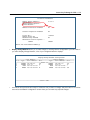
Copyright
Copyright © 2007 by Motorola, Inc.
All rights reserved. No part of this publication may be reproduced in any form or by any means or used to
make any derivative work (such as translation, transformation or adaptation) without written permission
from Motorola, Inc.
Motorola reserves the right to revise this publication and to make changes in content from time to time
without obligation on the part of Motorola to provide notification of such revision or change. Motorola
provides this guide without warranty of any kind, either implied or expressed, including, but not limited to,
the implied warranties of merchantability and fitness for a particular purpose. Motorola may make
improvements or changes in the product(s) described in this manual at any time. MOTOROLA and the
Stylized M Logo are registered in the US Patent & Trademark Office. Microsoft, Windows, Windows Me,
and Windows NT are either trademarks or registered trademarks of Microsoft Corporation in the U.S and/or
other countries. Macintosh is a registered trademark of Apple, Inc. Firefox is a registered trademark of the
Mozilla Foundation. All other product or service names are the property of their respective owners.
Motorola, Inc.
1303 East Algonquin Road
Schaumburg, Illinois 60196
USA
Version 8.7.4
Part Number
6161252-00-01
Contents
Contents
iii
Chapter 1 — Introduction..........................................................1-1
What’s New in 8.7.4 ...................................................... 1-1
Telnet-based Management.............................................. 1-2
Motorola Netopia® Telnet Menus.................................... 1-2
Motorola Netopia® Models............................................. 1-3
Screen differences .............................................. 1-3
Connecting through a Telnet Session............................... 1-4
Configuring Telnet software................................... 1-4
Navigating through the Telnet Screens............................. 1-5
Chapter 2 — WAN Configuration................................................2-1
WAN Configuration ......................................................... 2-1
WAN Ethernet Configuration screen ....................... 2-1
ADSL Line Configuration screen ............................ 2-4
Creating a New Connection Profile................................... 2-8
Advanced Connection Options....................................... 2-15
Configuration Changes Reset WAN Connection..... 2-15
Scheduled Connections...................................... 2-16
Backup Configuration ......................................... 2-21
Diffserv Options ................................................ 2-22
Priority Queuing (TOS bit).................................... 2-25
VRRP Options (WAN Link Failure Detection).......... 2-26
Chapter 3 — System Configuration............................................3-1
System Configuration Features ....................................... 3-1
IP Setup........................................................................ 3-2
Filter Sets ..................................................................... 3-2
IP Address Serving ........................................................ 3-2
Network Address Translation (NAT) .................................. 3-2
Stateful Inspection......................................................... 3-3
Add Exposed Address List .................................... 3-3
Exposed Address Associations ............................. 3-7
VLAN Configuration ...................................................... 3-11
Overview ........................................................... 3-11
G
iv
Administrator’s Handbook
Ethernet Switching/Policy Setup ......................... 3-12
Associating Inter-VLAN Routing Groups ................ 3-17
Adding a RADIUS Profile ..................................... 3-18
Adding Port interfaces ....................................... 3-20
Changing or Deleting a VLAN............................... 3-23
Changing or Deleting an Authentication Server
Configuration ..................................................... 3-24
Configuring additional Authentication Servers....... 3-25
VLAN Example ................................................... 3-27
Date and time ............................................................. 3-37
Wireless configuration .................................................. 3-38
Wireless Multimedia (WMM) ............................... 3-40
Enable Privacy ................................................... 3-41
Multiple SSIDs................................................... 3-45
MAC Address Authentication............................... 3-47
Console Configuration .................................................. 3-49
SNMP (Simple Network Management Protocol)............... 3-50
Security ...................................................................... 3-50
Upgrade Feature Set .................................................... 3-50
Router/Bridge Set........................................................ 3-51
IGMP (Internet Group Management Protocol) ................. 3-52
Logging ....................................................................... 3-55
Log event dispositions ....................................... 3-56
Procedure for Default Installation for ICSA firewall certification
of Small/Medium Business Category Module
(ADSL Routers) ............................................................ 3-60
Chapter 4 — Multi-NAT .............................................................4-1
Overview ....................................................................... 4-1
Features ............................................................. 4-2
Supported traffic ................................................. 4-5
Support for AOL Instant Messenger (AIM)
File Transfer ........................................................ 4-5
Support for Yahoo Messenger............................... 4-5
Contents
v
MultiNAT Configuration ................................................... 4-6
Easy Setup Profile configuration ............................ 4-6
Server Lists and Dynamic NAT configuration........... 4-7
System Configuration ........................................... 4-7
Modifying map lists ............................................ 4-12
Adding Server Lists...................................................... 4-15
Modifying server lists ......................................... 4-18
Deleting a server ............................................... 4-20
Binding Map Lists and Server Lists ............................... 4-21
IP profile parameters.......................................... 4-21
IP Parameters (WAN Default Profile) .................... 4-23
NAT Associations ......................................................... 4-25
IP Passthrough ............................................................ 4-27
MultiNAT Configuration Example .................................... 4-30
Chapter 5 — Virtual Private Networks (VPNs)............................5-1
Overview ....................................................................... 5-1
About PPTP Tunnels ....................................................... 5-4
PPTP configuration ............................................... 5-4
About IPsec Tunnels....................................................... 5-7
About L2TP Tunnels ....................................................... 5-7
L2TP configuration ............................................... 5-8
About GRE Tunnels ...................................................... 5-10
VPN force-all...................................................... 5-12
About ATMP Tunnels..................................................... 5-14
ATMP configuration ............................................ 5-14
Encryption Support ...................................................... 5-16
MS-CHAP V2 and 128-bit strong encryption ......... 5-17
ATMP/PPTP Default Profile............................................ 5-17
VPN QuickView ............................................................ 5-18
Dial-Up Networking for VPN ........................................... 5-19
Installing Dial-Up Networking............................... 5-20
Creating a new Dial-Up Networking profile ............ 5-21
G
vi
Administrator’s Handbook
Configuring a Dial-Up Networking profile ...............
Windows XP Client Configuration .........................
Connecting using Dial-Up Networking...................
Allowing VPNs through a Firewall ...................................
PPTP example....................................................
ATMP example ...................................................
Windows Networking Broadcasts...................................
5-21
5-23
5-23
5-23
5-24
5-27
5-30
Chapter 6 — Internet Key Exchange for VPNs ............................6-1
Overview ....................................................................... 6-1
Internet Key Exchange (IKE) Configuration........................ 6-2
Adding an IKE Phase 1 Profile ............................... 6-4
Changing an IKE Phase 1 Profile ........................... 6-9
Key Management......................................................... 6-11
Advanced IPsec Options ..................................... 6-14
IPsec WAN Configuration Screens ................................. 6-21
IPsec Manual Key Entry................................................ 6-22
VPN Quickview ................................................... 6-23
WAN Event History Error Reporting ...................... 6-24
Chapter 7 — IP Setup ...............................................................7-1
IP Setup........................................................................ 7-1
IP subnets........................................................... 7-3
Static routes ....................................................... 7-6
RIP Options ................................................................... 7-9
Overview ............................................................. 7-9
Authentication configuration................................ 7-10
Connection Profiles and Default Profile ................ 7-15
IP Address Serving ...................................................... 7-17
IP Address Pools................................................ 7-19
DHCP NetBIOS Options ...................................... 7-21
More Address Serving Options...................................... 7-23
Configuring the IP Address Server options ........... 7-24
DHCP Relay Agent........................................................ 7-28
Contents
Connection Profiles ......................................................
Multicast Forwarding....................................................
Virtual Router Redundancy (VRRP) ......................
Additional LANs .................................................
vii
7-30
7-32
7-34
7-38
Chapter 8 — Line Backup .........................................................8-1
Configuring Backup ........................................................ 8-1
Connection Profiles ........................................................ 8-2
IP Setup .............................................................. 8-6
WAN Configuration ......................................................... 8-7
Backup Configuration screen ................................ 8-9
Using Scheduled Connections with Backup .................... 8-12
Backup Default Gateway............................................... 8-14
Backup Configuration screen .............................. 8-14
IP Setup screen ................................................. 8-16
Backup Management/Statistics .................................... 8-16
QuickView ................................................................... 8-18
Chapter 9 — Monitoring Tools ...................................................9-1
Quick View Status Overview............................................ 9-1
General status..................................................... 9-2
Current status ..................................................... 9-2
Status lights........................................................ 9-3
Statistics & Logs ........................................................... 9-3
Event Histories .............................................................. 9-4
IP Routing Table............................................................. 9-6
General Statistics .......................................................... 9-6
System Information........................................................ 9-8
Simple Network Management Protocol (SNMP)................. 9-8
The SNMP Setup screen....................................... 9-9
SNMP traps....................................................... 9-11
Chapter 10 — Security ...........................................................10-1
Suggested Security Measures....................................... 10-1
G
viii
Administrator’s Handbook
Telnet Tiered Access – Two Password Levels ................. 10-1
UPnP Support.................................................... 10-2
Superuser configuration ..................................... 10-3
Limited user configuration .................................. 10-3
Advanced Security Options ........................................... 10-5
RADIUS server authentication ............................. 10-6
TACACS+ server authentication........................... 10-7
Warning alerts ................................................... 10-8
User access password ..................................... 10-11
User menu differences..................................... 10-12
Telnet Access ............................................................ 10-19
About Filters and Filter Sets........................................ 10-20
What’s a filter and what’s a filter set? ............... 10-20
How filter sets work ......................................... 10-20
How individual filters work ................................ 10-21
Design guidelines ............................................ 10-26
Working with IP Filters and Filter Sets .......................... 10-27
Adding a filter set............................................. 10-27
Deleting a filter set .......................................... 10-32
A sample filter set............................................ 10-32
Policy-based Routing using Filtersets ........................... 10-35
TOS field matching ........................................... 10-37
Firewall Tutorial ......................................................... 10-38
General firewall terms ...................................... 10-38
Basic IP packet components............................. 10-38
Basic protocol types......................................... 10-38
Firewall design rules ........................................ 10-39
Filter basics..................................................... 10-41
Example filters................................................. 10-42
Configuration Management ......................................... 10-45
TFTP ............................................................... 10-48
Contents
ix
Chapter 11 — Utilities and Diagnostics ...................................11-1
Ping ............................................................................ 11-2
Trace Route................................................................. 11-4
Telnet Client ................................................................ 11-5
Factory Defaults .......................................................... 11-6
Transferring Configuration and Software Files with TFTP .. 11-6
Updating software.............................................. 11-7
Downloading configuration files ........................... 11-7
Uploading configuration files ............................... 11-8
Restarting the System ................................................. 11-8
Appendix A — Troubleshooting..................................................A-1
Configuration Problems .................................................. A-1
Network problems................................................ A-2
How to Reset the Router to Factory Defaults.................... A-2
Power Outages .............................................................. A-3
Technical Support .......................................................... A-3
Before contacting Motorola................................... A-3
Environment profile .............................................. A-3
How to reach us .................................................. A-4
Online product information ................................... A-4
Index
G
x
Administrator’s Handbook
Introduction 1-1
Chapter 1
Introduction
This Administrator’s Handbook covers the advanced features of the Motorola Netopia® ENT Enterprise-Series
Router family.
Your Motorola Netopia® equipment offers advanced configuration features accessed through the Main Menu of
the Telnet configuration screen. This Administrator’s Handbook documents the advanced features, including
advanced testing, security, monitoring, and configuration. This Administrator’s Handbook should be used as a
companion to the Quickstart Guide and the Getting Started Guide. You should read the Quickstart Guide and
the Getting Started Guide before reading this Administrator’s Handbook.
What’s New in 8.7.4
New in Motorola Netopia® Embedded Software Version 8.7.4 are the following features:
•
Specify Source Address of Outbound Router Traffic. See “Enhanced Dead Peer Detection” on page 6-15.
•
Ability to support multiple networks over the same IPSec tunnel. See “Multiple Network IPsec” on
page 6-17.
•
Backup timer can now be set in seconds instead of minutes. Minimum failure setting has been reduced to
10 seconds. See Chapter 8, “Line Backup.”
•
USB-equipped models now support Macintosh Mac OS X on the USB port.
•
VLAN enhancements. See “VLAN Configuration” on page 3-11.
•
IP multicast to layer 2 unicast mapping. See “IGMP (Internet Group Management Protocol)” on
page 3-52.
Corresponding commands have been added to the Command Line Interface (CLI). In addition:
•
DHCP Generic Options support.
•
DHCP filtersets support.
•
Support for router generated packets with their source address outside the local member range for IPSec
force all tunnels.
See the Command Line Interface Commands Reference available on the Motorola Netopia® website.
1-2 Administrator’s Handbook
Telnet-based Management
Telnet-based management is a fast menu-driven interface for the capabilities built into Motorola Netopia®
Embedded Software Version 8.7.4. Telnet-based management provides access to a wide variety of features that
the Router supports. You can customize these features for your individual setup. This chapter describes how to
access the Telnet-based management screens. This section covers the following topics:
•
“Motorola Netopia® Telnet Menus” on page 1-2
•
“Motorola Netopia® Models” on page 1-3
•
“Connecting through a Telnet Session” on page 1-4
•
“Navigating through the Telnet Screens” on page 1-5
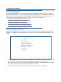
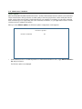
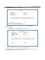
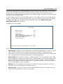
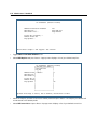
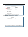
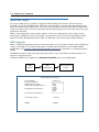
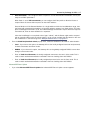
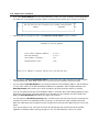
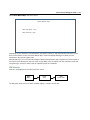
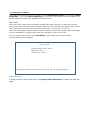
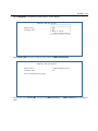
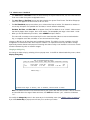
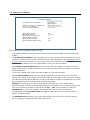
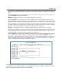
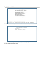
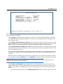
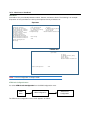
Motorola Netopia® Telnet Menus
Telnet-based management screens contain the main entry points to Motorola Netopia® Embedded Software
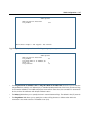
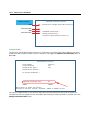
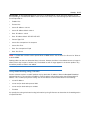
Version 8.7.4 configuration and monitoring features. The entry points are displayed in the Main Menu shown
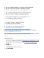
below:
Netopia 3366 V 8.7.4
Easy Setup...
WAN Configuration...
System Configuration...
Utilities & Diagnostics...
Statistics & Logs...
Quick Menus...
Quick View...
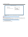
•
The Easy Setup menus display and permit changing the values contained in the default connection profile.
You can use Easy Setup to initially configure the Router directly through a Telnet session.
Easy Setup menus contain up to five descendant screens for viewing or altering these values. The number
of screens depends on whether you have optional features installed.
The Quickstart Guide describes the Easy Setup menus to get you up and running quickly.
Introduction 1-3
•
The WAN Configuration menu displays and permits changing your connection profile(s), Virtual Private
Networks (VPNs) and default profile, creating or deleting additional connection profiles, and configuring or
reconfiguring the manner in which you may be using the Router to connect to more than one service
provider or remote site. See “WAN Configuration,” beginning on page 2-1. See also Chapter 5, “Virtual
Private Networks (VPNs).”
•
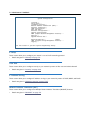
The System Configuration menus display and permit changing:
• IP Setup
• Filter Sets
• IP Address Serving
• Network Address Translation (NAT)
• Date and Time
• SNMP (Simple Network Management Protocol)
• Security
• Upgrade Feature Set
• Change Device to a Bridge
• Logging
and more. See “System Configuration Features,” beginning on page 3-1.
•
The Utilities & Diagnostics menus provide a selection of the various tools for monitoring and diagnosing
the Router's behavior, as well as for updating the software and rebooting the system. See Chapter 11,
“Utilities and Diagnostics.”
•
The Statistics & Logs menus display several sets of tables and device logs that show information about
your Router, your network, and their history. See “Statistics & Logs,” beginning on page 9-3.
•
The Quick Menus screen is a shortcut entry point to a variety of the most commonly used configuration
menus that are accessed through the other menu entry points.
•
The Quick View menu displays at a glance current real-time operating information about your Router. See
“Quick View Status Overview” on page 9-1.
Motorola Netopia® Models
This Administrator’s Handbook covers all of the Motorola Netopia® ENT Enterprise-Series Router models.
However some information in this guide will only apply to a specific model.
Screen differences
Because different Motorola Netopia® ENT Enterprise-Series models offer many different features and
interfaces, the options shown on some screens in this Administrator’s Handbook may not appear on your own
particular model’s Telnet screen.
These differences are noted throughout the manual.
1-4 Administrator’s Handbook
Connecting through a Telnet Session
Features of Motorola Netopia® Embedded Software Version 8.7.4 can be configured through the Telnet
screens.
Before you can access the console screens through Telnet, you must have:
•
A network connection locally to the Router or IP access to the Router.
•
Telnet software installed on the computer you will use to configure the Router
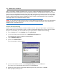
Configuring Telnet software
If you are configuring your device using a Telnet session, your computer must be running a Telnet software
program.
•
If you connect a PC with Microsoft Windows, you can use a Windows Telnet application or run Telnet from
the Start menu.
•
If you connect a Macintosh computer, Mac OS X users can use the Terminal application that comes with
Mac OS X in the Utilities folder.
Introduction 1-5
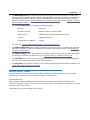
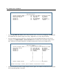
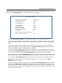
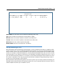
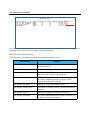
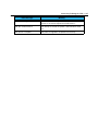
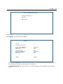
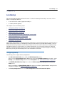
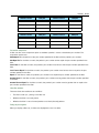
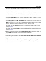
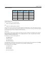
Navigating through the Telnet Screens
Use your keyboard to navigate the Motorola Netopia® Embedded Software Version 8.7.4’s configuration
screens, enter and edit information, and make choices. The following table lists the keys to use to navigate
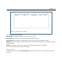
through the Telnet screens.
To...
Use These Keys...
Move through selectable items in a screen or pop-up menu
Up, Down, Left, and Right Arrow
Set a change to a selected item or open a pop-up menu of
options for a selected item like entering an upgrade key
Return or Enter
Change a toggle value (Yes/No, On/Off)
Tab
Restore an entry or toggle value to its previous value
Esc
Move one item up
Up arrow or Control + O
Move one item down
Down arrow or Control + K
Page up
Control + A
Page down
Control + Z
Display a dump of the device event log
Control + E
Display a dump of the WAN event log
Control + F
Refresh the screen
Control + L
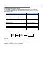
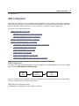
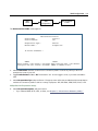
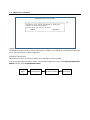
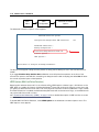
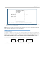
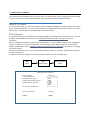
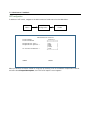
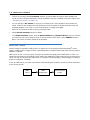
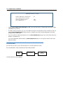
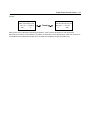
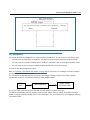
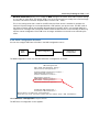
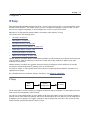
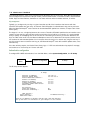
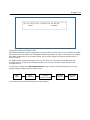
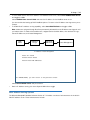
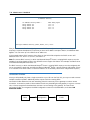
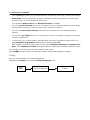
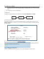
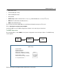
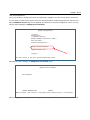
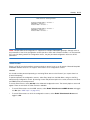
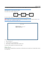
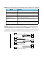
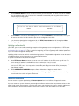
To help you find your way to particular screens, some sections in this guide begin with a graphical path guide
similar to the following example:
Main
Menu
System
Configuration
IP Setup
This particular path guide shows how to get to the Network Protocols Setup screens. The path guide represents
these steps:
1.
Beginning in the Main Menu, select System Configuration and press Return. The System Configuration
screen appears.
2.
Select IP Setup and press Return. The IP Setup screen appears.
To go back in this sequence of screens, use the Escape key.
1-6 Administrator’s Handbook
WAN Configuration 2-1
Chapter 2
WAN Configuration
This chapter describes how to use the Telnet-based management screens to access and configure advanced
features of your equipment. You can customize these features for your individual setup. These menus provide a
powerful method for experienced users to set up their Router’s connection profiles configuration.
This section covers the following topics:
•
“WAN Configuration” on page 2-1
•
“WAN Ethernet Configuration screen” on page 2-1
•
“ADSL Line Configuration screen” on page 2-4
•
“Creating a New Connection Profile” on page 2-8
•
“Advanced Connection Options” on page 2-15
•
“Configuration Changes Reset WAN Connection” on page 2-15
•
“Scheduled Connections” on page 2-16
•
“Backup Configuration” on page 2-21
•
“Diffserv Options” on page 2-22
•
“Priority Queuing (TOS bit)” on page 2-25
•
“VRRP Options (WAN Link Failure Detection)” on page 2-26
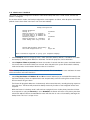
WAN Configuration
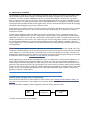
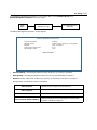
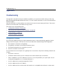
To configure your Wide Area Network (WAN) connection, navigate to the WAN Configuration screen from the Main
Menu and select WAN (Wide Area Network) Setup.
Main
Menu
WAN
Configuration
WAN
Setup
The Line Configuration screen appears. The Line Configuration screen will be appropriate to the type of WAN
interface supported by your particular Router model.
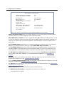
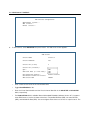
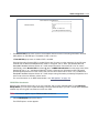
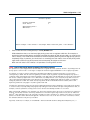
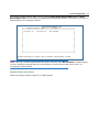
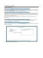
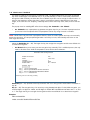
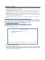
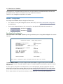
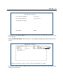
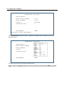
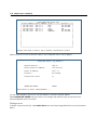
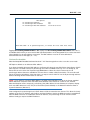
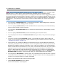
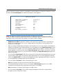
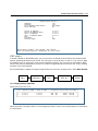
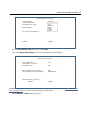
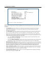
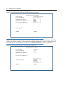
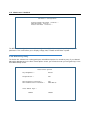
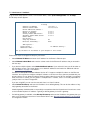
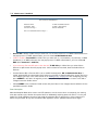
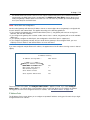
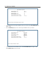
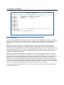
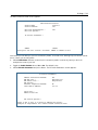
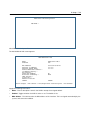
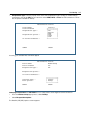
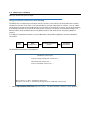
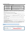
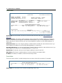
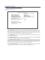
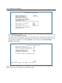
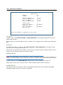
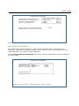
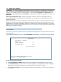
WAN Ethernet Configuration screen
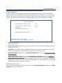
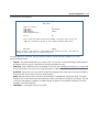
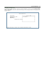
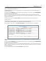
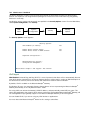
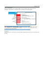
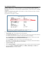
The WAN Ethernet Configuration screen appears as follows:
2-2 Administrator’s Handbook
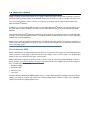
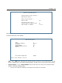
WAN Ethernet Configuration
Address Translation Enabled:
Obtain WAN address via DHCP:
Yes
On
NAT Map List...
NAT Server List...
NAT Options...
Stateful Inspection Enabled:
Easy-PAT List
Easy-Servers
No
Filter Set...
Remove Filter Set
WAN Ethernet Speed Setting...
Wan Ethernet MAC Address:
Auto-Negotiation
00:0f:cc:0b:9d:ce
DHCP Client Mode:
Standards-Based
RIP Options...
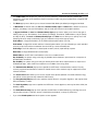
Set up the basic IP attributes of your Ethernet Module in this screen.
•
Address Translation Enabled allows you to specify whether or not the router performs Network Address
Translation (NAT) on the Ethernet WAN port. NAT is enabled by default.
•
Obtain WAN address via DHCP allows you to toggle WAN DHCP Off and On. DHCP is On by default. so that
if you do not change the setting, the Router will acquire its WAN IP address automatically. By default, the
router acts as a DHCP client on the Ethernet WAN port and and attempts to acquire an address from a
DHCP server.
•
The Local WAN IP Address field allows you to manually configure an IP address for use on the Ethernet
WAN port. This field only becomes visible if you toggle Obtain WAN address via DHCP to Off.
•
The Local WAN IP Mask field becomes visible if you specify a Local WAN IP Address. This allows you to
manually configure an IP subnet mask for use on the Ethernet WAN port. This item is visible only if you
have configured a non-zero Ethernet IP Address; otherwise, the router obtains a subnet mask via DHCP.
•
The NAT Map List and NAT Server List options are set to the defaults, Easy-PAT List and Easy-Servers.
These provide standard NAT mappings. For more advanced NAT configurations, see “Multi-NAT” on
page 4-1.
•
NAT Options allows you to specify IP Passthrough, allowing a single PC on the LAN to have the router’s
public address assigned to it. See “IP Passthrough” on page 4-27.
•
If you set Stateful Inspection Enabled to Yes, you can enable a security feature for computers on your LAN
when NAT is disabled. See “Stateful Inspection” on page 3-3.
•
The Filter Set pop-up allows you to associate an IP filter set with the Ethernet WAN port. See “About Filters
and Filter Sets” on page 10-20.
•
Remove Filter Set allows you to remove a previously associated filter set.
•
The WAN Ethernet Speed Setting is configurable via a pop-up menu. Options are:
•
Auto-Negotiation (the default)
WAN Configuration 2-3
•
100 Mbps Full Duplex
•
100 Mbps Half Duplex
•
10 Mbps Full Duplex
•
10 Mbps Half Duplex
•
100 Mbps, Full Duplex, Fixed
•
100 Mbps, Half Duplex, Fixed
•
10 Mbps, Full Duplex, Fixed
•
10 Mbps, Half Duplex, Fixed
This may be useful in mixed networks, where multiple routers have different ethernet speed capability. If
you want to maintain a single speed setting for compatibility with multiple routers on your LAN, you can
select a speed/duplex combination that all of your routers can match.
•
The Wan Ethernet MAC Address is the hardware address of the Motorola Netopia® device. Some service
providers require a specific MAC address as part of their authentication process. In such a case, you can
enter the MAC address that your service provider requires. If your service provider doesn’t use this
method, you don’t need to change this field.
•
The DHCP Client Mode setting depends on the type of access concentrator equipment your service
provider uses. Most use Standards-Based. Alternatively, your provider may instruct you to select Copper
Mountain Specific.
•
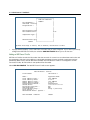
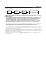
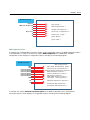
The RIP Options selection displays the WAN Ethernet RIP Parameters screen.
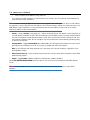
Receive RIP:
•
WAN Ethernet RIP Parameters
+----------------+
+----------------+
| Off
|
| v1
|
| v2
|
| Both v1 and v2 |
| v2 MD5 Authentication
+----------------+
The Receive RIP pop-up menu controls the reception and transmission of Routing Information Protocol
(RIP) packets on the Ethernet WAN port. The default is Both.
2-4 Administrator’s Handbook
The Transmit RIP pop-up menu is hidden if NAT is enabled.
Routing Information Protocol (RIP) is needed if there are IP routers on other segments of your Ethernet
network that the Motorola Netopia® Router needs to recognize. Set to “Both” (the default) Motorola
Netopia® Embedded Software Version 8.7.4 will accept information from either RIP v1 or v2 routers.
Alternatively, select Receive RIP and select v1, v2, or v2 MD5 Authentication from the popup menu. With
Receive RIP set to “v1,” the Motorola Netopia® Router’s Ethernet port will accept routing information
provided by RIP packets from other routers that use the same subnet mask. Set to “v2,” the Motorola
Netopia® Embedded Software Version 8.7.4 will accept routing information provided by RIP packets from
other routers that use different subnet masks.
For more information on v2 MD5 Authentication, see “RIP Options” on page 7-9.
If you want the Motorola Netopia® Router to advertise its routing table to other routers via RIP, select
Transmit RIP and select v1, v2 (broadcast), or v2 (multicast) from the popup menu. With Transmit RIP v1
selected, the Motorola Netopia® Embedded Software Version 8.7.4 will generate RIP packets only to other
RIP v1 routers. With Transmit RIP v2 (broadcast) selected, the Motorola Netopia® Embedded Software
Version 8.7.4 will generate RIP packets to all other hosts on the network. With Transmit RIP v2 (multicast)
selected, the Motorola Netopia® Embedded Software Version 8.7.4 will generate RIP packets only to other
routers capable of recognizing RIP v2 packets.
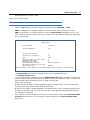
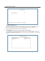
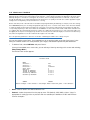
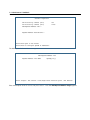
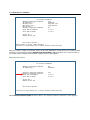
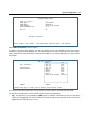
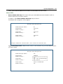
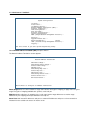
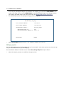
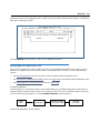
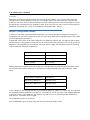
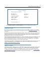
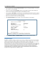
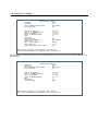
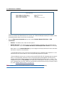
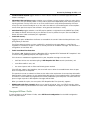
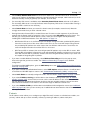
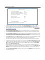
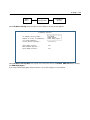
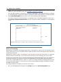
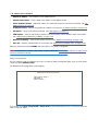
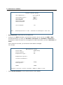
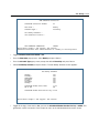
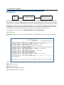
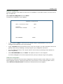
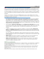
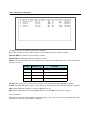
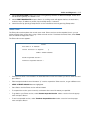
ADSL Line Configuration screen
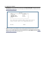
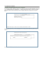
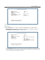
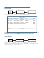
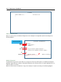
The ADSL Line Configuration screen is shown below:
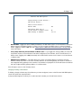
ADSL Line Configuration
Circuit Type...
Trellis Coding Enabled:
Multimode
On
Signaling Mode...
Fast Retrain Enabled:
FDM
On
Wiring Type...
Data Link Encapsulation...
Annex Modes enabled:
AutoSense
RFC1483
Off
1.
Select Circuit Type and from the pop-up menu choose the type of circuit to which you will be connecting:
Multimode, T1.413, G.dmt, or G.lite.
2.
Select Trellis Coding Enabled. Toggle it to On (the default) or Off.
3.
Select Signaling Mode and choose Echo Cancellation or FDM (the default).
4.
If you selected Multimode Circuit Type, the Fast Retrain Enabled field appears. Toggle it to On (the default)
or Off.
WAN Configuration 2-5
5.
For model 3341 and 3366C ADSL modems, a Wiring Type pop-up menu allows you to choose the type of
copper pair wiring in use at your location. For all other models this option is preset and does not appear.
Usually, the default AutoSense will detect the type and adjust itself accordingly. If you want to set it
yourself, and you know the type of wiring you have, choose either Tip/Ring (Inner Pair) or A/A1 (Outer Pair)
from the pop-up menu.
6.
Select Data Link Encapsulation and press Return. The pop-up menu will offer you the choice of PPP or
RFC1483.
7.
Toggle Annex Modes enabled to On only if your service provider supports it. The embedded software has
the ability to support Annex M mode. However, Annex M mode may affect the training timing in some
cases. Consequently, the default is Off. Not all services support this feature for all subscribers.
ATM Circuit Configuration
On ADSL WAN interfaces, the Asynchronous Transfer Mode (ATM) connection between the router and the
central office equipment (DSLAM) is divided logically into one or more virtual circuits (VCs). A virtual circuit may
be either a permanent virtual circuit (PVC) or a switched virtual circuit (SVC). Motorola Netopia® Routers
support PVCs.
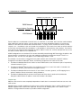
VCs are identified by a Virtual Path Identifier (VPI) and Virtual Channel Identifier (VCI). A VPI is an 8-bit value
between 0 and 255, inclusive, while a VCI is a 16-bit value between 0 and 65535, inclusive.
•
Circuits support attributes in addition to their VPI and VCI values. When configuring a circuit, you can
specify an optional circuit name of up to 14 characters. The circuit name is used only to identify the circuit
for management purposes as a convenience to aid in selecting circuits from lists. The default circuit name
is “Circuit <n>”, where <n> is some number between one and eight corresponding to the circuit’s position
in the list of up to eight circuits.
•
You can also individually enable or disable a circuit without deleting it. This is useful for temporarily
removing a circuit without losing the configured attributes.
•
In order to function, each circuit must be bound to a Connection Profile or to the Default Profile. Among
other attributes, the profile binding specifies the IP addressing information for use on the circuit. Each
circuit must be bound to a distinct Connection Profile.
ATM VPI/VCI Autodetection. You can bind multiple circuits to the same Connection Profile. Motorola Netopia®
Embedded Software Version 8.7.4 allows you to have a standard configuration that uses, for example, four VCs
(0/35, 0/38, 8/35, 8/38) pointing to the same profile.
The unit will now automatically select the active VC on networks with a VPI/VCI of any of these four values
without any custom configuration of the unit. You must, however, manually create these VCs and associate
them with the profile you desire.
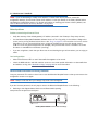
You configure Virtual Circuits in the Add/Change Circuit screen.
Main
Menu
WAN
Configuration
ATM Circuits
Configuration
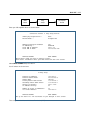
2-6 Administrator’s Handbook
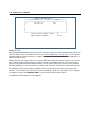
ATM Circuits Configuration
Show/Change Circuit...
Add Circuit...
Delete Circuit...
8.
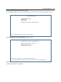
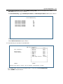
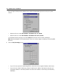
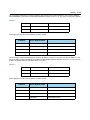
To add a circuit, select Add Circuit and press Return. The Add Circuit screen appears.
Add Circuit
Circuit Name:
Circuit 2
Circuit Enabled:
Yes
Circuit VPI (0-255):
0
Circuit VCI (32-65535):
QoS...
Peak Cell Rate (0 = line rate):
Use Connection Profile...
Use Default Profile for Circuit
ADD Circuit NOW
+-------------+
+-------------+
| UBR
|
| CBR
|
| VBR
|
+-------------+
Default Profile
CANCEL
•
Enter a name for the circuit in the Circuit Name field.
•
Toggle Circuit Enabled to Yes.
•
Enter the Virtual Path Identifier and the Virtual Channel Identifier in the Circuit VPI and Circuit VCI
fields, respectively.
•
The Peak Cell Rate field is editable. Motorola Netopia® Embedded Software Version 8.7.4 supports
three ATM classes of service for data connections: Unspecified Bit Rate (UBR), Constant Bit Rate
(CBR), and Variable Bit Rate (VBR). You can configure these classes of service on a per VC basis. The
WAN Configuration 2-7
default ATM class of service is UBR.
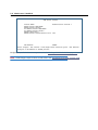
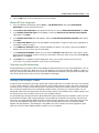
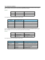
Quality of Service (QoS) settings
Note: QoS settings are not available on Ethernet-to-Ethernet WAN models.
•
Select the QoS (Quality of Service) setting from the pop-up menu: UBR. CBR, or VBR.
UBR: No configuration is needed for UBR VCs. Leave the default value 0 (maximum line rate).
CBR: One parameter is required for CBR VCs. Enter the Peak Cell Rate that applies to the VC. This
value should be between 1 and the line rate. You set this value according to specifications defined by
your service provider.
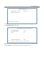
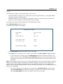
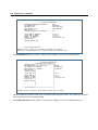
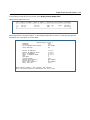
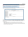
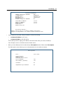
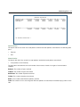
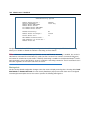
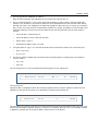
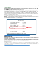
Add Circuit
Circuit Name:
Circuit 2
Circuit Enabled:
Yes
Circuit VPI (0-255):
0
Circuit VCI (32-65535):
32
QoS...
Peak Cell Rate (0 = line rate):
Sustained Cell Rate:
Maximum Burst Size:
Use Connection Profile...
Use Default Profile for Circuit
ADD Circuit NOW
VBR
0
0
0
Default Profile
CANCEL
Return accepts * ESC cancels * Left/Right moves insertion point * Del deletes.
VBR: This class is characterized by:
• a Peak Cell Rate (PCR), which is a temporary burst, not a sustained rate, and
• a Sustained Cell Rate (SCR),
• a Burst Tolerance (BT), specified in terms of Maximum Burst Size (MBS). The MBS is the maximum
number of cells that can be transmitted at the peak cell rate and should be less than, or equal to the
Peak Cell Rate, which should be less than, or equal to the line rate.
VBR has two sub-classes:
a. VBR non-real-time (VBR-nrt): Typical applications are non-real-time traffic, such as IP data traffic.
This class yields a fair amount of Cell Delay Variation (CDV).
b. VBR real time (VBR-rt): Typical applications are real-time traffic, such as compressed voice over IP
and video conferencing. This class transmits cells with a more tightly bounded Cell Delay Variation.
The applications follow CBR.
•
Then, select a Connection Profile for the Circuit. To use the Default Profile, select Use Default Profile
for Circuit and press Return. For other options, select a profile from the Use Connection Profile
pop-up menu.
2-8 Administrator’s Handbook
Note: With multiple VCs you must explicitly statically bind the second (and all subsequent) VCs to a profile.
The first VC will automatically statically bind according to pre-defined dynamic binding rules when you add the
second VC. It will revert back to dynamic binding if the number of VCs is reduced to one; for example, by
deleting previously defined VCs.
When the link comes up the router binds the VC dynamically to the first suitable Connection Profile or to the
Default Profile if there is no Connection Profile configured.
• If you factory default the router, the VC binds to the Default Profile.
• If you delete a Connection Profile that is statically bound to a VC, the VC binding is set back to the Default
Profile. If there is only one VC defined, the VC dynamically binds to the first suitable profile or to the Default
Profile. If there are multiple VCs defined, it binds to the Default Profile.
• If you add a second VC, it is initialized to the Default Profile, and the menu screens display the VC
Connection Profile-related items, allowing you to bind to a specific Connection Profile instead of the Default
Profile. In addition, the router statically binds the first VC according to the rules used to select a profile for
dynamic binding. At this point, each profile uses static binding when the link is brought up.
• If there are no VCs when you add a VC -- for example, if you deleted all your previous VCs and started adding
them again -- dynamic binding will occur when the link comes up. If you delete a VC, leaving only one VC, that VC
resumes dynamically binding again.
•
9.
Select ADD Circuit NOW and press Return.
To display or change a circuit, select Display/Change Circuit, select a circuit from the pop-up menu, and
press Return. The fields are the same as those in the Add Circuit screen.
10. To delete a circuit, select Delete Circuit, select a circuit from the pop-up menu, and press Return. In the
confirmation window, select CONTINUE and press Return.
11. Press Escape to return to the WAN Setup menu.
Creating a New Connection Profile
Connection profiles are useful for configuring the connection and authentication settings for negotiating a PPP
connection. If you are using the PPP data link encapsulation method, you can store your authentication
information in the connection profile so that your user name and password (or host name and secret) are
transmitted when you attempt to connect.
Connection profiles define the networking protocols necessary for the Router to make a remote connection. A
connection profile is like an address book entry describing how the Router is to get to a remote site, or how to
recognize and authenticate a connection. To create a new connection profile, you navigate to the WAN
Configuration screen from the Main Menu, and select Add Connection Profile.
WAN Configuration 2-9
WAN
Configuration
Main
Menu
Add Connection
Profile
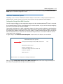
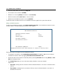
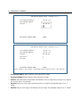
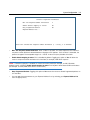
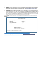
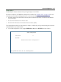
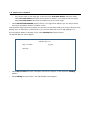
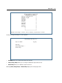
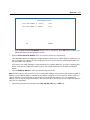
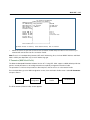
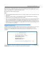
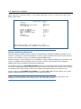
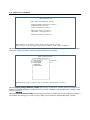
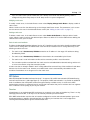
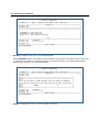
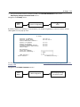
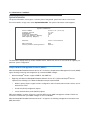
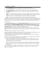
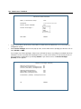
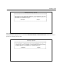
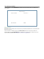
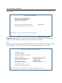
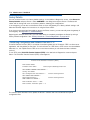
The Add Connection Profile screen appears.
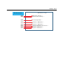
Add Connection Profile
Profile Name:
Profile Enabled:
Profile 1
Yes
Encapsulation Type...
RFC1483
RFC1483 Mode...
Bridged 1483
IP Profile Parameters...
COMMIT
CANCEL
Return accepts * ESC cancels * Left/Right moves insertion point * Del deletes.
Configure a new Conn. Profile. Finished? COMMIT or CANCEL to exit.
1.
Select Profile Name and enter a name for this connection profile. It can be any name you wish. For
example: the name of your ISP.
2.
Toggle Profile Enabled to Yes or No. The default is Yes. You can toggle it to No, if you want to disable it
later.
3.
Select Encapsulation Type and press Return. The pop-up menu offers the possible data link encapsulation
methods for connection profiles used for a variety of purposes: PPP, RFC1483, ATMP, PPTP, IPsec, L2TP.
Multiple Data Link Encapsulation Settings
4.
Select Encapsulation Options and press Return.
•
If you selected ATMP, PPTP, L2TP, or IPSec, see Chapter 5, “Virtual Private Networks (VPNs).”
2-10 Administrator’s Handbook
•
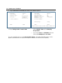
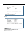
If you selected PPP or RFC1483, the screen offers different options:
Add Connection Profile
Profile Name:
Profile Enabled:
Encapsulation Type...
RFC1483 Mode...
Add Connection Profile
Profile 1
Yes
+--------------+
+--------------+
| Bridged 1483 |
| Routed 1483 |
+--------------+
IP Profile Parameters...
COMMIT
Profile Name:
Profile Enabled:
Profile 1
Yes
Encapsulation Type...
Underlying Encapsulation...
PPP Mode...
Encapsulation Options...
PPP
None
VC Multiplexed
IP Profile Parameters...
CANCEL
Interface Group...
Primary
COMMIT
CANCEL
Configure a new Conn. Profile. Finished?
•
If you selected RFC1483, the screen allows you
to choose Bridged 1483 or Routed 1483.
COMMIT or CANCEL to exit.
•
If you selected PPP, the screen allows you to
choose PPPoE or None as the Underlying
Encapsulation.
•
If you choose None, the PPP Mode offers the
choice of VC Multiplexed or LLC SNAP.
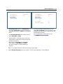
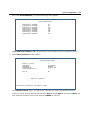
If you are using PPP, when you select Encapsulation Options, the Datalink (PPP/MP) Options screen
appears. (RFC1483 does not require these options and does not offer the menu selection.)
WAN Configuration 2-11
Datalink (PPP/MP) Options
Datalink (PPP/MP) Options
Data Compression...
Standard LZS
Data Compression...
Standard LZS
Send Authentication...
PAP
Send Authentication...
PAP
Send User Name:
Send Password:
Receive User Name:
Receive Password:
•
Data Compression defaults to Standard LZS. You
can select Ascend LZS, if you are connecting to
compatible equipment, or None from the pop-up
menu.
•
The Send Authentication pop-up menu lets you
select PAP, CHAP, or None.
•
Selecting PAP or CHAP allows you to enter your
authentication credentials for both sending and
receiving connections.
PAP requires a User Name and Password;
CHAP requires a Host Name and Secret.
The screen changes to accommodate your
selection.
Send User Name:
Send Password:
Receive User Name:
Receive Password:
•
Dial on Demand:
Yes
Idle Timeout (seconds):
300
If you are creating a Backup profile, you can
toggle Dial on Demand to Yes (the default) or No
and adjust the idle timeout in seconds from the
default 300 (5 minutes).
See “Line Backup” on page 8-1 for more
information.
Return to the Add Connection Profile screen by pressing Escape.
5.
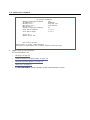
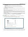
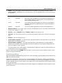
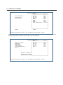
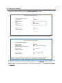
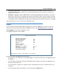
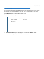
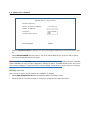
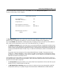
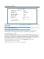
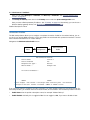
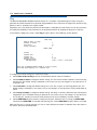
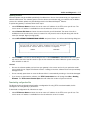
Select IP Profile Parameters and press Return. The IP Profile Parameters screen appears.
2-12 Administrator’s Handbook
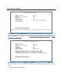
IP Profile Parameters
Address Translation Enabled:
IP Addressing...
NAT Map List...
NAT Server List...
NAT Options...
Stateful Inspection Enabled:
Yes
Numbered
Easy-PAT List
Easy-Servers
Local WAN IP Address:
Local WAN IP Mask:
0.0.0.0
0.0.0.0
No
Filter Set...
Remove Filter Set
RIP Profile Options...
Return/Enter to select <among/between> ...
Configure IP requirements for a remote network connection here.
6.
Toggle or enter your IP Parameters.
For more information, see:
•
“IP Setup” on page 7-1
•
“Network Address Translation (NAT)” on page 3-2
•
“Stateful Inspection Options” on page 3-8
•
“Filter Sets” on page 3-2
•
The RIP Profile Options selection displays the RIP Profile Parameters screen.
WAN Configuration 2-13
Receive RIP:
•
RIP Profile Parameters
+-----------------------+
+-----------------------+
| Off
|
| v1
|
| v2
|
| Both v1 and v2
|
| v2 MD5 Authentication |
+-----------------------+
The Receive RIP pop-up menu controls the reception and transmission of Routing Information Protocol
(RIP) packets on the WAN port. The default is Both v1 and v2.
A Transmit RIP pop-up menu is hidden if NAT is enabled.
Routing Information Protocol (RIP) is needed if there are IP routers on other segments of your Ethernet
network that the Motorola Netopia® Router needs to recognize. Set to “Both” (the default) Motorola
Netopia® Embedded Software Version 8.7.4 will accept information from either RIP v1 or v2 routers.
Alternatively, select Receive RIP and select v1, v2, or v2 MD5 Authentication from the popup menu. With
Receive RIP set to “v1,” the Motorola Netopia® Router’s Ethernet port will accept routing information
provided by RIP packets from other routers that use the same subnet mask. Set to “v2,” the Motorola
Netopia® Embedded Software Version 8.7.4 will accept routing information provided by RIP packets from
other routers that use different subnet masks.
For more information on v2 MD5 Authentication, see “RIP Options” on page 7-9.
PPPoE/PPPoA Autodetection
Beginning with Software Version 8.5, if you are using PPP, and you have selected PPPoE as the Underlying
Encapsulation, you can further enable the ability to connect automatically to your ISP’s central office equipment
whether they are using PPP over Ethernet or PPP over ATM.
Note: This feature applies only to ATM-based WAN connections.
7.
Select PPPoE Options and press Return.
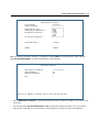
The PPPoE Options screen appears.
2-14 Administrator’s Handbook
PPPoE Options
PPPoA Autodetect:
No
Return/Enter accepts * Tab toggles * ESC cancels.
Toggle PPPoA Autodetect to On.
If your ISP is using PPPoE, the connection will be made normally. If your ISP is using PPPoA, when the
Motorola Netopia® Gateway detects this, it will automatically switch to PPPoA transparently.
8.
Return to the Add Connection Profile screen by pressing Escape.
9.
Select COMMIT and press Return. Your new Connection Profile will be added.
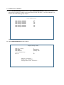
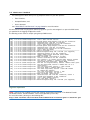
If you want to view the Connection Profiles in your device, return to the WAN Configuration screen, and
select Display/Change Connection Profile. The list of Connection Profiles is displayed in a scrolling pop-up
screen.
WAN Configuration
+-Profile Name---------------------IP Address------+
+--------------------------------------------------+
| Easy Setup Profile
255.225.255.255 |
| Profile 1
0.0.0.0
|
|
|
|
|
|
|
|
|
|
|
|
|
|
|
|
|
|
|
|
|
|
|
|
|
|
|
|
|
+--------------------------------------------------+
WAN Configuration 2-15
You can also delete Connection Profiles by selecting them in the same manner using the Delete Connection
Profile option in the WAN Configuration screen.
Advanced Connection Options
Depending on your model, the Advanced Connection Options screen offers a variety of powerful options for
advanced users. Screens shown in this section may vary from what your particular model displays.
Configuration Changes Reset WAN Connection
The menu supports delaying some configuration changes until after the Motorola Netopia® Router is restarted.
If your Motorola Netopia® Router is preconfigured by your service provider, or if you are not remotely configuring
the router, you can leave this setting unchanged.
The purpose of this feature is to defer configuration changes only when remotely configuring or reconfiguring the
Motorola Netopia® Router to prevent premature Telnet disconnection. When this feature is enabled, no changes
to the WAN setup, datalink encapsulation, Connection Profiles, or Default Gateway will take effect until after the
Motorola Netopia® Router is restarted. Until the Motorola Netopia® Router is restarted the WAN link and the
routing table remain unaffected.
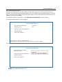
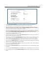
A single setting in the Advanced Connection Options screen controls this feature, as shown below.
Advanced Connection Options
Configuration Changes Reset WAN Connection:
Yes
Scheduled Connections...
Backup Configuration...
Prioritize Delay-Sensitive Data: No
Diffserv Options...
VRRP Options...
Return/Enter to configure SA Backup Parameters.
When you toggle Configuration Changes Reset WAN Connection either to Yes or No using the Tab key and
press Return, a pop-up window asks you to confirm your choice.
2-16 Administrator’s Handbook
Advanced Connection Options
+----------------------------------------------------+
+----------------------------------------------------+
| The Router will now be restarted to allow this
|
| feature to function properly.
|
| Are you sure you want to do this?
|
|
|
|
CANCEL
CONTINUE
|
|
|
+----------------------------------------------------+
No
Toggling from Yes to No makes the router ready to be configured. If you toggle from No to Yes after any
configuration changes have been entered (and confirm the reboot), your changes are committed and the router
comes up using the newly created configuration.
Scheduled Connections
Scheduled connections are useful for PPPoE, PPTP, and ATMP connection profiles.
To go to the Scheduled Connections screen, from the WAN Configuration screen select Advanced Connection
Options and then select Scheduled Connections.
Main
Menu
WAN
Configuration
Advanced
Connection Options
Scheduled
Connections
WAN Configuration 2-17
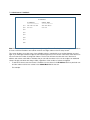
Scheduled Connections
Display/Change Scheduled Connection...
Add Scheduled Connection...
Delete Scheduled Connection...
Navigate from here to add/modify/change/delete Scheduled Connections.
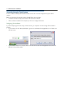
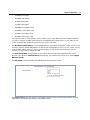
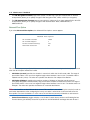
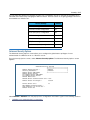
Viewing scheduled connections
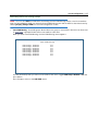
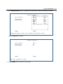
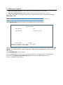
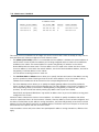
To display a table of scheduled connections, select Display/Change Scheduled Connection in the Scheduled
Connections screen. Each scheduled connection occupies one row of the table.
Scheduled Connections
+-Days----Begin At---HH:MM---When----Conn. Prof. Name----Enabled-----+
+--------------------------------------------------------------------+
| mtWtfss 08:30PM
06:00
weekly Profile 01
No
|
|
|
|
|
|
|
|
|
|
|
+--------------------------------------------------------------------+
The first column in the table shows a one-letter representation of the Days of the week, from Monday (M or m)
to Sunday (S or s). If a letter representing a day is capitalized, the connection will be activated on that day; a
lower-case letter means that the connection will not be activated on that day. If the scheduled connection is
configured for a once-only connection, the word “once” will appear instead of the days of the week.
The other columns show:
2-18 Administrator’s Handbook
•
The time of day that the connection will Begin At
•
The duration of the connection (HH:MM)
•
Whether it’s a recurring Weekly connection or used Once Only
•
Which connection profile (Conn. Prof.) is used to connect
•
Whether the scheduled connection is currently Enabled
The Router checks the date and time set in scheduled connections against the system date and time.
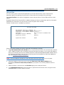
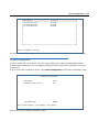
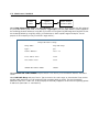
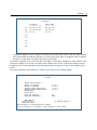
Adding a scheduled connection
To add a new scheduled connection, select Add Scheduled Connection in the Scheduled Connections screen
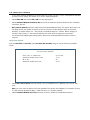
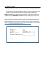
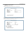
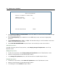
and press Return. The Add Scheduled Connection screen appears.
Add Scheduled Connection
Scheduled Connection Enable:
On
How Often...
Weekly
Schedule Type...
Forced Up
Set Weekly Schedule...
Use Connection Profile...
ADD SCHEDULED CONNECTION
CANCEL
Scheduled Connections dial remote Networks on a Weekly or Once-Only basis.
Follow these steps to configure the new scheduled connection:
•
To activate the connection, select Scheduled Connection Enable and toggle it to On. You can make the
scheduled connection inactive by toggling Scheduled Connection Enable to Off.
•
Decide how often the connection should take place by selecting How Often and choosing Weekly or Once
Only from the pop-up menu.
•
The Schedule Type allows you to set the exact weekly schedule or once-only schedule.
Options are:
•
Forced Up, meaning that this connection will be maintained whether or not there is a demand call on
the line.
•
Forced Down, meaning that this connection will be torn down or blocked whether or not there is a
demand call on the line.
WAN Configuration 2-19
•
Demand-Allowed, meaning that this schedule will permit a demand call on the line.
•
Demand-Blocked, meaning that this schedule will prevent a demand call on the line.
•
Periodic, meaning that the connection is retried several times during the scheduled time.
•
Random Retry, which operates as follows:
First, it will wait 0 to 60 seconds before starting, then it will try three times to bring the connection up as
quickly as possible;
Second, on each successive retry after these first three attempts it will wait a random number of seconds
between zero and a user-specified maximum.
Should the connection come up, and subsequently go down, the Scheduled Connection will start over with
three retries. Switched connections have a variable redial back-off time depending on the interface type.
Consequently, the first three attempts for such connections will be slower. Once the connection is up it will
be forced to remain up.
•
If How Often is set to Weekly, the item directly below How Often reads Set Weekly Schedule. If How Often
is set to Once Only, the item directly below How Often reads Set Once-Only Schedule.
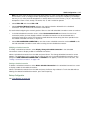
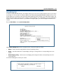
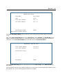
Set Weekly Schedule
If you set How Often to Weekly, select Set Weekly Schedule and go to the Set Weekly Schedule screen.
•
Select the days for the scheduled connection to occur and toggle them to Yes.
Set Weekly Schedule
Monday:
Tuesday:
Wednesday:
Thursday:
Friday:
Saturday:
Sunday:
No
No
No
No
No
No
No
Scheduled Window Start Time:
AM or PM:
04:29
AM
Scheduled Window Duration Per Day: 00:00
Retry interval (minutes):
5
Return/Enter accepts * Tab toggles * ESC cancels.
•
Select Scheduled Window Start Time and enter the time to initiate the scheduled connection.
•
You must enter the time in the format H:M, where H is a one- or two-digit number representing the hour and
M is a one- or two-digit number representing the minutes. The colon is mandatory. For example, the entry
2-20 Administrator’s Handbook
1:3 (or 1:03) would be accepted as 3 minutes after one o’clock. The entry 7:0 (or 7:00) would be accepted
as seven o’clock, exactly. The entries 44, :5, and 2: would be rejected.
•
Select AM or PM and choose AM or PM from the pop-up menu.
•
Select Scheduled Window Duration Per Day and enter the maximum duration allowed for this scheduled
connection, per call.
•
Retry interval (minutes) becomes visible if you have selected Random Retry. This option allows you to set
the upper limit for the number of minutes to use for the retry time (the attempts after the first three
attempts). It accepts values of 1 – 255 minutes; the default setting is 5 minutes. With a setting of 5
minutes it will try every 0 – 300 seconds after the first three retries to bring up the connection.
You are finished configuring the weekly options. Return to the Add Scheduled Connection screen to
continue.
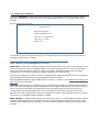
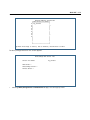
Set Once-Only Schedule
If you set How Often to Once Only, select Set Once-Only Schedule and go to the Set Once-Only Schedule
screen.
Set Once-Only Schedule
•
Place Call on (MM/DD/YY):
05/07/1998
Scheduled Window Start Time:
AM or PM:
11:50
AM
Scheduled Window Duration:
00:00
Select Place Call On (Date) and enter a date in the format MM/DD/YY or MM/DD/YYYY (month, day,
year).
Note: You must enter the date in the format specified. The slashes are mandatory. For example, the entry
5/7/98 would be accepted as May 7, 1998. The entry 5/7 would be rejected.
•
Select Scheduled Window Start Time and enter the time to initiate the scheduled connection.
WAN Configuration 2-21
Note: You must enter the time in the format H:M, where H is a one- or two-digit number representing the
hour and M is a one- or two-digit number representing the minutes. The colon is mandatory. For example,
the entry 1:3 (or 1:03) would be accepted as 3 minutes after one o’clock. The entry 7:0 (or 7:00) would be
accepted as seven o’clock, exactly. The entries 44, :5, and 2: would be rejected.
•
Select AM or PM and choose AM or PM.
•
Select Scheduled Window Duration and enter the maximum duration allowed for this scheduled
connection. Use the same format restrictions noted above.
You are finished configuring the once-only options. Return to the Add Scheduled Connection screen to continue.
•
In the Add Scheduled Connection screen, select Use Connection Profile and choose from the list of
connection profiles you have already created. A scheduled connection must be associated with a
connection profile to be useful. The connection profile becomes active during the times specified in the
associated scheduled connection, if any exists.
•
Select ADD SCHEDULED CONNECTION to save the current scheduled connection. Select CANCEL to exit
the Add Scheduled Connection screen without saving the new scheduled connection.
Modifying a scheduled connection
To modify a scheduled connection, select Display/Change Scheduled Connection in the Scheduled
Connections screen to display a table of scheduled connections.
Select a scheduled connection from the table and press Return. The Change Scheduled Connection screen
appears. The parameters in this screen are the same as the ones in the Add Scheduled Connection screen
(except that ADD SCHEDULED CONNECTION and CANCEL do not appear). To find out how to set them, see
“Adding a scheduled connection” on page 2-18.
Deleting a scheduled connection
To delete a scheduled connection, select Delete Scheduled Connection in the Scheduled Connections screen
to display a table of scheduled connections.
Select a scheduled connection from the table and press the Return key to delete it. To exit the table without
deleting the selected scheduled connection, press the Escape key.
Backup Configuration
See “Line Backup” on page 8-1.
2-22 Administrator’s Handbook
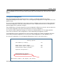
Diffserv Options
Motorola Netopia® Embedded Software Version 8.7.4 offers Differentiated Services (Diffserv) enhancements.
These enhancements allow your Router to make Quality of Service (QoS) decisions about what path Internet
traffic, such as Voice over IP (VoIP), should travel across your network. For example, you may want streaming
video conferencing to use high quality, but more restrictive, connections, or, you might want e-mail to use less
restrictive, but less reliable, connections.
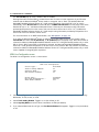
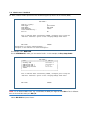
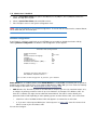
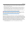
When you select Diffserv Options, the Diffserve Options configuration screen appears.
Diffserv Options
Diffserv Enabled:
•
No
Differentiated Services is disabled by default. To enable Differentiated Services, toggle Diffserv Enabled to
Yes and press Return.
The Diffserv options are displayed.
WAN Configuration 2-23
Diffserv Options
Diffserv Enabled:
Lo/Hi Ratio:
Yes
0
Show/Change Rules...
Add Rules...
Return accepts * ESC cancels * Left/Right moves insertion point * Del deletes.
•
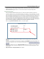
Enter a value from 60 to 100 (percent) in the Lo/Hi Ratio field.
Differentiated Services uses the low-to-high priority queue ratio to regulate traffic flow. For example, to
provide the least possible latency and highest possible throughput for high priority traffic, you could set the
ratio to 100(%). This would cause the Router to forward low priority data only after the high priority queue is
completely empty. In practice, you should set it to something less than 100%, since the low priority traffic
might have to wait too long to be passed, and consequently be subject to time-outs.
When the LoHi value is 50 or below, it is equivalent to turning off the service.
Note: Low to High Priority Queue Asymmetry Field (lohi-asymmetry)
This parameter is a percentage between 50 and 100 used to regulate the level of packets allowed to be pending in the low
priority queue. It can be used to some degree to adjust the relative throughput bandwidth for low vs. high priority traffic.
For example, to provide for least possible latency and highest throughput for high priority packets, you can set the
lohi-asymmetry to 100%. This will cause the gateway to forward low priority packets only when the high priority queue is
completely empty. If the high priority stream throughput is such that it fully loads the Gateway, the low priority stream will in
this case be completely suppressed. If it is a TCP stream, it probably will time out. To keep low priority TCP connections
“alive” with minimal throughput while other applications are loading the Gateway with high priority traffic, you might try
setting the parameter to 90%. The means a low priority packet will be forwarded whenever the relative packet count
asymmetry, defined as (low)/(high + low) with is greater than .90.
Lowering the lohi-asymmetry value will lower the throughput and widen the latency distribution of the high priority streams,
so for best results, especially during heavy high priority loading, the value should be left high. Setting the field to 50%, for
example, is almost equivalent to turning off the service as far as the Gateway's behavior is concerned.
Much of the benefit of DiffServe is a cumulative one observed as packets traverse the nodes on a network from endpoint to
endpoint. A small improvement in the latency distribution for the flow through a single network node (such as a Motorola
Netopia® “edge” Gateway) may not be especially noticeable in a VoIP conversation, for example. If the latency for the VoIP
packets in a stream can be minimized through 10 or 20 nodes in the route to the other end of the conversation, however,
the cumulative difference may be very noticeable.
In general, a VoIP call, for example, is low bandwidth – bi-directional UDP streams totaling about 20 packets/sec, or
2-24 Administrator’s Handbook
bandwidths from 20 kbps to 90 kbps, depending on the CODEC setting – compared to the total throughput bandwidth of the
Gateway and the network. There will usually be fewer than two or three packets pending in the Gateway in any queue in the
Gateway during the conversation. If, during the call, however, a user is surfing and decides to download, or upload, a file
through the Gateway, it is possible that during the file transfer the voice quality of the VoIP call could be degraded. A higher
setting for the lohi-asymmetry will prevent this from occurring.
On the other hand, if 10 or 20 VoIP calls are simultaneously being handled by the Gateway, for example, in an office setting,
then 1000-2000 packets/sec are being throughput at high priority. If one or several of the callers in the office then attempt
to download, 10-15 packets may be pending in the low priority receive queues, with perhaps 2-3 pending in the high. The
corresponding asymmetry in this case would be around 80-86%. If it were found in this situation that the file transfers were
too sluggish, then the lohi-asymmetry threshold could be set to 80%. This would cause more of the low priority traffic to be
throughput, at the expense of the high priority streams. As a result, the file downloads might proceed at a more satisfactory
rate, while the degradation to the 10 or 20 VoIP calls might not be noticeable.
The lo-hi asymmetry parameter is therefore one means of balancing the traffic load to satisfy everyone.
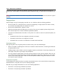
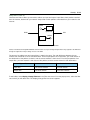
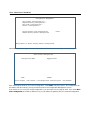
You can then define custom Rules. If your applications do not provide Quality of Service (QoS) control, rules
allow you to define streams for some protocols, port ranges, and between specific end point addresses.
•
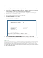
To define a Rule, select Add Rules and press Return.
(Once you have added one or more rules, you can edit any of them by returning to this screen and selecting
Show/Change Rules.)
The Diffserv Rule screen appears.
Diffserv Rule
Name:
Protocol...
TCP
Priority...
Direction...
Start Port:
End Port:
Inside Ip Address:
Inside Ip Netmask:
Outside Ip Address:
Outside Ip Netmask:
off
outbound
0
0
0.0.0.0
0.0.0.0
0.0.0.0
0.0.0.0
COMMIT
CANCEL
Return accepts * ESC cancels * Left/Right moves insertion point * Del deletes.
•
Name – Enter a name in this field to label the rule.
•
Protocol – Select the protocol from the pop-up menu: TCP (default), UDP, ICMP, or Other. “Other” is
appropriate for setting up rules on protocols with non-standard port definitions. IPSEC and PPTP are
common examples.
WAN Configuration 2-25
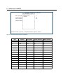
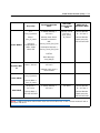
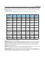
•
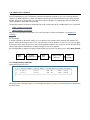
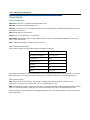
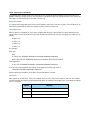
Priority – This is the Quality of Service setting for the rule, based on the TOS bit information. Select
assure, expedite, or off (default) from the pop-up menu. The following table outlines the TOS bit settings
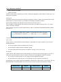
and behavior:
QoS Setting
TOS Bit Value
Behavior
off
TOS=000
This custom rule is disabled. You can activate it by selecting one of
the two settings below. This setting allows you to pre-define flows
without actually activating them.
assure
TOS=001
Use normal queuing and throughput rules, but do not drop packets
if possible. Appropriate for applications with no guaranteed delivery
mechanism.
expedite
TOS=101
Use minimum delay. Appropriate for VoIP and video applications.
•
Numerical Protocol – If you select “Other” protocol, this field appears for you to provide its actual protocol
number, with a range of 0 – 255.
•
Direction – Choose outbound (default), inbound, or both from the pop-up menu.
•
Start Port – For TCP or UDP protocols, you can optionally specify a range of ports. Enter the starting port
here.
•
End Port – Enter the ending port here.
•
Inside IP Address/Netmask – For outbound flows, specify an IP address and subnet mask on your LAN. For
inbound flows, this setting is ignored.
•
Outside IP Address/Netmask – If you want traffic destined for and originating from a certain WAN IP
address to be controlled, enter the IP address and subnet mask here. If you leave the default all-zeroes,
the outside address check is ignored.
For outbound flows, the outside address is the destination IP address for traffic; for inbound packets, the
outside address is the source IP address.
When you are finished, select COMMIT and press Return. You will be returned to the Diffserv Options screen
and your settings will take effect.
Priority Queuing (TOS bit)
Motorola Netopia® Embedded Software Version 8.7.4 offers the ability to prioritize delay-sensitive data over the
WAN link on DSL connections.
Certain types of IP packets, such as voice or multimedia packets, are sensitive to latency introduced by the
network. This means that if such packets are not received rapidly, the quality of service degrades. If you expect
to route significant amounts of such traffic you can configure your router to prioritize this type of traffic using the
priority queuing feature.
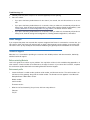
To configure your router to prioritize delay-sensitive data, navigate to the Advanced Connection Options screen
in the console menu.
2-26 Administrator’s Handbook
Main
Menu
WAN
Configuration
Advanced Connection
Options
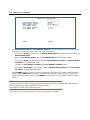
The Advanced Connection Options screen appears.
Advanced Connection Options
Configuration Changes Reset WAN Connection:
Yes
Scheduled Connections...
Backup Configuration...
Prioritize Delay-Sensitive Data: No
Diffserv Options...
VRRP Options...
Return/Enter to configure SA Backup Parameters.
The Router will recognize a delay-sensitive packet as having the low-latency bit set in the TOS field of the IP
header.
If you toggle Prioritize Delay-Sensitive Data to Yes the router will place these packets at the front of the
transmission queue to the WAN link, overtaking non-delay-sensitive traffic. Accepting the default No will allow
the normal sequential queue of data packets.
VRRP Options (WAN Link Failure Detection)
Beginning with Software Version 8.5.1, the software offers VRRP Options to detect Layer 3 link failures on the
WAN. When you enable this feature, the Motorola Netopia® Router will continuously Ping one or two hosts that
you specify to determine when a link fails, even if the physical connection remains established. If Layer 3 WAN
Link Failure Detection is enabled, the Motorola Netopia® Router will send continuous Pings, so the WAN link will
stay up and idle timeout will not occur.
See “Virtual Router Redundancy (VRRP)” on page 7-34 for a detailed description of VRRP and how to create
Virtual Routers.
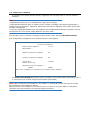
To enable WAN Link Failure Detection, select VRRP Options in the Advanced Connection Options menu. The
VRRP Options menu appears.
WAN Configuration 2-27
VRRP Options
WAN Link Failure Detection:
Ping Enable:
Off
Return/Enter accepts * Tab toggles * ESC cancels.
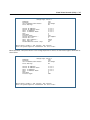
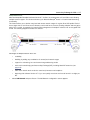
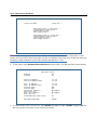
Toggle Ping Enable to On and press Return. The Ping settings options appear.
VRRP Options
WAN Link Failure Detection:
Ping Enable:
Ping Host Name or IP Address #1:
Ping Host Name or IP Address #2:
Delay (s):
Ping failures:
On
5
10
•
The Ping Host Name or IP Address #1 and Ping Host Name or IP Address #2 fields allow you to enter the
fully-qualified host name(s) or IP address(es) in standard dotted-quad format of the hosts you want to Ping
for connection validation. If no ICMP echo(es) are returned from these hosts, the connection is assumed to
be lost, and the Virtual Router will relinquish Master status.
•
The Delay (s) field allows you to specify the time in seconds between Pings. The default is five (5) seconds.
•
The Ping failures field allows you to specify the number of Ping time-outs or failures after which the
connection is assumed to be lost. The default is ten (10).
2-28 Administrator’s Handbook
System Configuration 3-1
Chapter 3
System Configuration
This chapter describes how to use the Telnet-based management screens to access and configure advanced
features of your equipment. You can customize these features for your individual setup. These menus provide a
powerful method for experienced users to set up their Router’s system configuration.
System Configuration Features
The Motorola Netopia® Router’s default settings may be all you need to configure. Some users, however,
require advanced settings or prefer manual control over the default selections. For these users, Motorola
Netopia® Embedded Software Version 8.7.4 provides many advanced system configuration options.
This section covers the following topics:
•
“IP Setup” on page 3-2
•
“Wireless configuration” on page 3-38
•
“Filter Sets” on page 3-2
•
“Console Configuration” on page 3-49
•
“IP Address Serving” on page 3-2
•
“SNMP (Simple Network Management Protocol)”
on page 3-50
•
“Network Address Translation (NAT)” on
page 3-2
•
“Security” on page 3-50
•
“Stateful Inspection” on page 3-3
•
“Upgrade Feature Set” on page 3-50
•
“Procedure for Default Installation for ICSA
firewall certification of Small/Medium
Business Category Module (ADSL Routers)”
on page 3-60
•
“Router/Bridge Set” on page 3-51
•
“VLAN Configuration” on page 3-11
•
“IGMP (Internet Group Management Protocol)”
on page 3-52
•
“Date and time” on page 3-37
•
“Logging” on page 3-55
To access the system configuration screens, select System Configuration in the Main Menu and press Return.
The System Configuration menu screen appears:
3-2 Administrator’s Handbook
System Configuration
IP Setup...
Filter Sets...
IP Address Serving...
Network Address Translation (NAT)...
Stateful Inspection...
VLAN Configuration...
Date and Time...
Wireless Configuration...
Console Configuration
SNMP (Simple Network Management Protocol)...
Security...
Upgrade Feature Set...
Router/Bridge Set...
Router
IGMP (Internet Group Management Protocol)...
Logging...
Use this screen if you want options beyond Easy Setup.
IP Setup
These screens allow you to configure your network’s use of the IP networking protocol.
•
Details are given in “IP Setup” on page 7-1.
Filter Sets
These screens allow you to configure security on your network by means of filter sets and a basic firewall.
•
Details are given in “Security” on page 10-1.
IP Address Serving
These screens allow you to configure IP address serving on your network by means of DHCP, WANIP, and BootP.
•
Details are given in “IP Address Serving” on page 7-17.
Network Address Translation (NAT)
These screens allow you to configure the Multiple Network Address Translation (MultiNAT) features.
•
Details are given in “Multi-NAT” on page 4-1.
System Configuration 3-3
Stateful Inspection
Stateful inspection is a security feature that prevents unsolicited inbound access when NAT is disabled.
Stateful inspection can be enabled on a Connection Profile whether NAT is enabled or not. You can configure
UDP and TCP “no-activity” periods that will also apply to NAT time-outs if stateful inspection is enabled on the
interface. Stateful Inspection parameters are active on a WAN interface only if enabled on your Gateway.
Stateful Inspection
UDP no-activity timeout (sec):
180
TCP no-activity timeout (sec):
14400
DoS Detect:
No
Add Exposed Address List...
Exposed Address Associations...
Return/Enter goes to new screen.
Return/Enter to configure Xposed IP addresses.
•
UDP no-activity time-out: The time in seconds after which a UDP session will be terminated, if there is no
traffic on the session.
•
TCP no-activity time-out: The time in seconds after which an TCP session will be terminated, if there is no
traffic on the session.
•
DoS Detect: If you toggle this option to Yes, the device will monitor packets for Denial of Service (DoS)
attack. Offending packets may be discarded if it is determined to be a DoS attack.
•
Add Exposed Address List: Accesses the Add Exposed Address List screen. See “Add Exposed Address
List” on page 3-3.
•
Exposed Address Associations: Accesses the Exposed Address Associations screen. See “Exposed
Address Associations” on page 3-7. The hosts specified in Exposed addresses will be allowed to receive
inbound traffic even if there is no corresponding outbound traffic. This is active only if NAT is disabled on a
WAN interface. An Exposed Address List can be associated with a Connection Profile only if NAT is disabled
and Stateful Inspection is enabled on the profile.
Add Exposed Address List
You can specify the IP addresses you want to expose by selecting Add Exposed Address List from the Stateful
Inspection menu and pressing Return.
3-4 Administrator’s Handbook
Stateful Inspection
UDP no-activity timeout (sec):
180
TCP no-activity timeout (sec):
14400
Add Exposed Address List...
Exposed Address Associations...
Return/Enter goes to new screen.
Return/Enter to configure Xposed IP addresses.
The Add Exposed Address List screen appears.
Add Exposed Address List
Exposed Address List Name:
xposed_list_1
Return accepts * ESC cancels * Left/Right moves insertion point * Del deletes.
Enter a descriptive name for the list and press Return. A new field Add Exposed Address Range appears.
System Configuration 3-5
Add Exposed Address List
Exposed Address List Name:
xposed_list_1
Add Exposed Address Range...
Return/Enter goes to new screen.
Select Add Exposed Address Range and press Return.
The Exposed Address Range screen appears.
Add Exposed Address Range ("xposed_list_1")
First Exposed Address:
0.0.0.0
Last Exposed Address:
0.0.0.0
Protocol...
ANY
ADD EXPOSED ADDRESS RANGE
CANCEL
Enter an IP address in decimal and dot form (xxx.xxx.xxx.xxx).
Enter the First and Last Exposed Addresses in dotted-quad format for the range of IP addresses you want to
expose,
The pop-up Protocol menu offers the type of protocols to be assigned to this range.
3-6 Administrator’s Handbook
Add Exposed Address Range ("xposed_list_1")
First Exposed Address:
192.168.1.10
Last Exposed Address:
+-------------+
+-------------+
| TCP and UDP |
| TCP
|
| UDP
|
| ANY
|
+-------------+
Protocol...
ADD EXPOSED ADDRESS RANGE
CANCEL
Add Exposed Address Range ("xposed_list_1")
First Exposed Address:
192.168.1.10
Last Exposed Address:
192.168.1.12
Protocol...
TCP and UDP
Port Start:
0
Port End:
0
ADD EXPOSED ADDRESS RANGE
CANCEL
Return accepts * ESC cancels * Left/Right moves insertion point * Del deletes.
•
First Exposed Address: Start IP Address of the exposed host range.
•
Last Exposed Address: End IP Address of the exposed host range
•
Protocol: Select the Protocol of the traffic to be allowed to the host range from the pop-up menu. Options
are Any, TCP, UDP, or TCP and UDP.
•
Port Start: Start port of the range to be allowed to the host range. The acceptable range is from 1 65535.
•
Port End: End port of the range to be allowed to the host range. The acceptable range is from 1 - 65535.
System Configuration 3-7
You can edit or delete exposed address lists by selecting Show/Change Exposed Address List or Delete
Exposed Address List. A list of previously configured exposed addresses appears. This allows you to select an
exposed address list for editing or deletion.
Add Exposed Address List
+------Exposed Address Range---------Protocol-------------------+
+---------------------------------------------------------------+
| 192.168.1.10
192.168.1.12
TCP and UDP
|
|
|
|
|
|
|
|
|
|
|
|
|
|
|
|
|
|
|
|
|
|
|
|
|
|
|
|
|
|
|
+---------------------------------------------------------------+
Up/Down Arrow Keys to select, ESC to dismiss, Return/Enter to Edit.
Note: Add, Edit, or Delete exposed addresses options are active only if NAT is disabled on a WAN interface.
The hosts specified in exposed addresses will be allowed to receive inbound traffic even if there is no
corresponding outbound traffic.
Exposed Address Associations
Enable and configure stateful inspection on a WAN interface.
3-8 Administrator’s Handbook
IP Profile Parameters
Address Translation Enabled:
IP Addressing...
NAT Map List...
NAT Server List...
NAT Options...
Stateful Inspection Enabled:
Yes
Numbered
Easy-PAT List
Easy-Servers
Local WAN IP Address:
Local WAN IP Mask:
0.0.0.0
0.0.0.0
No
Filter Set...
Remove Filter Set
RIP Profile Options...
Return/Enter to select <among/between> ...
Configure IP requirements for a remote network connection here.
When you create or modify a Connection Profile, the IP Profile Parameters screen allows you to enable Stateful
Inspection on that profile by toggling Stateful Inspection Enabled to Yes. By default, this is turned off (No). If
you enable Stateful Inspection, the Stateful Inspection Options field appears.
Stateful Inspection Options
IP Profile Parameters
Address Translation Enabled:
IP Addressing...
No
Numbered
Stateful Inspection Enabled:
Stateful Inspection Options...
Local WAN IP Address:
Local WAN IP Mask:
Yes
0.0.0.0
0.0.0.0
Filter Set...
Remove Filter Set
RIP Profile Options...
Configure IP requirements for a remote network connection here.
Select Stateful Inspection Options and press Return. The Stateful Inspection Parameters screen appears.
System Configuration 3-9
Stateful Inspection Parameters
Max. TCP Sequence Number Difference:
0
Enable default mapping to router:
No
Deny Fragmented Packets:
No
Exposed Address List...
Enter max. allowed TCP sequence number difference (1 - 65535), 0 to disable.
•
Max. TCP Sequence Number Difference: Enter a value in this field. This value represents the maximum
sequence number difference allowed between subsequent TCP packets. If this number is exceeded, the
packet is dropped. The acceptable range is 0 – 65535. A value of 0 (zero) disables this check.
•
Enable default mapping to router: This is disabled by default. Toggling this option to Yes will allow the
router to respond to traffic received on this interface, for example, ICMP Echo requests.
Note: If Stateful Inspection is enabled on a base connection profile (for example, for PPP, RFC1483
bridged/routed, or PPPoE), Enable default mapping to router must be yes to allow inbound VPN terminations.
(for example. for PPTP/ATMP client access to the router)
•
Deny Fragmented Packets: Toggling this option to Yes causes the router to discard fragmented packets on
this interface.
•
You can apply these parameters to your Exposed Address lists by selecting your Exposed Address List
from the pop-up menu,
3-10 Administrator’s Handbook
Stateful Inspection Parameters
+Exposed Address List N+
+----------------------+
Max. TCP Sequ| xposed_list_1
|
0
| <<None>>
|
Enable defaul|
|
No
|
|
Deny Fragment|
|
No
|
|
Exposed Addre|
|
|
|
|
|
|
|
|
|
|
|
|
|
|
|
|
|
|
|
+----------------------+
Up/Down Arrows to select, then Return/Enter; ESC to cancel.
Open ports in default Stateful Inspection installation
Port
Protocol
Description
Private Interface
Public Interface
23
TCP
telnet
Yes
No
53
UDP
DNS
Yes
No
67
UDP
Bootps
Yes
No
68
UDP
Bootpc
Yes
No
80
TCP
HTTP
Yes
No
137
UDP
Netbios-ns
Yes
No
138
UDP
Netbios-dgm
Yes
No
161
UDP
SNMP
Yes
No
500
UDP
ISAKMP
Yes
No
520
UDP
Router
Yes
No
1701
UDP
L2TP
Yes
No
1900
UDP
UPnP
Yes
No
1723
TCP
PPTP
Yes
No
System Configuration 3-11
VLAN Configuration
Overview
A Virtual Local Area Network (VLAN) is a network of computers or other devices that behave as if they are
connected to the same wire even though they may be physically located on different segments of a LAN. You
set up VLANs by configuring the Gateway software rather than hardware. This makes VLANs very flexible. VLANs
behave like separate and independent networks.
Beginning with Version 8.7.4, VLANs are now strictly layer 2 entities. They can be thought of as virtual Ethernet
switches, into which can be added: Ethernet ports, router IP interfaces, ATM PVC/VCC interfaces, SSIDs, and
any other physical port such as USB, HPNA, or MOCA. This allows great flexibility in how the components of a
system are connected to each other.
VLANs are part of Motorola’s VGx Virtual Gateway technology which allows individual port-based VLANs to be
treated as separate and distinct “channels.” When data is passed to a Motorola Netopia® VGx-enabled
broadband gateway, specific policies, routing, and prioritization parameters can be applied to each individual
service, delivering that service to the appropriate networked device with the required level of quality of service
(QoS). In effect, a single Motorola gateway acts as separate virtual gateways for each distinct service being
delivered.
Motorola’s VGx technology provides service segmentation and QoS controls, and supports delivery of triple play
applications: voice for IP Telephony, video for IPTV, and data.
Your Gateway supports the following:
•
Global VLANs - these are used when trunking/tagging is required on any port member of the VLAN. Trunks
are used to interconnect switches to form networks. The VLANs can communicate with each other via a
trunking connection between the two switches using the router.
- Supports 802.1q and 802.1p; both are configurable
•
Port-based VLANs - these can be used when no trunking is required
•
Routed VLANs
- WAN-side VLAN with Multiple WAN IPoE/PPPoE interface support and IP interface-to-VLAN binding
- LAN-side VLAN with IP interface-to-VLAN binding
- Inter-VLAN routing groups to extend VLAN segmentation up through the IP routing layer.
•
Bridged VLANs - these VLANs are used to bridge traffic from LAN to WAN
•
Prioritization per VLAN and per port
3-12 Administrator’s Handbook
Ethernet Switching/Policy Setup
Before you configure any VLANs, an unconfigured Gateway is set up as a router composed of a LAN switch, a
WAN switch, and a router in the middle, with LAN and WAN IP interfaces connected to their respective switches.
These bindings between Ethernet switch ports, IP LAN interface, IP WAN interface and WAN physical ports are
automatically created.
When you configure any VLANs, the default bindings are no longer valid, and the system requires explicit binding
between IP interfaces and layer 2 interfaces. Each VLAN can be thought of as a layer 2 switch, and enabling
each port or interface in a VLAN is analogous to plugging it in to the layer 2 switch.
Thereafter, in order for devices to communicate on layer 2, they must be associated in the same VLAN. For
devices to communicate at layer 3, the devices must be either on the same VLAN, or on VLANs that have an
Inter-VLAN routing group enabled in common.
When configuring VLANs you must define how traffic needs to be forwarded:
•
If traffic needs to be bridged between LAN and WAN you can create a single VLAN that encompasses the
WAN port and LAN ports.
•
If traffic needs to be routed then you must define four elements:
• LAN-side VLANs
• WAN-side VLANs
• Associate IP Interfaces to VLANs
• Inter-VLAN Routing Groups: configuration of routing between VLANs is done by association of a VLAN to a
Routing Group. Traffic will be routed between VLANs within a routing group. The LAN IP Ethernet Interface
can be bound to multiple LAN VLANs, but forwarding can be limited between an Ethernet LAN port and a
WAN VLAN if you properly configure Inter-VLAN groups.
Inter-VLAN groups are also used to block routing between WAN interfaces. If each WAN IP interface is
bound to its own VLAN and if you configure a different Inter-VLAN group for each WAN VLAN then no routing
between WAN IP interfaces is possible.
•
Example: to route between a VCC and all the LAN ports, which effectively is similar to the default
configuration without any VLANs:
Create a VLAN named "WAN" consisting of your Connection Profile and Inter-VLAN-Routing Group-1
Create a VLAN named "LAN" consisting of Eth 0/1, Eth 0/2, Eth 0/3, Eth 0/4, SSID 1, SSID 2, SSID 3,
SSID 4 (etc.), and Inter-VLAN-Routing Group-1
System Configuration 3-13
An example of multiple VLANs, using a Netopia Router with VGx managed switch technology, is shown below:
A VLAN Model Combining Bridging and Routing
3-14 Administrator’s Handbook
To configure VLANs, select VLAN Configuration in the System Configuration screen and press Return.
The VLAN Configuration screen appears.
VLAN Configuration
VLAN Enable:
Off
Set Up VLAN from this and the following Menus.
Toggle VLAN Enable to On and press Return.
The Add VLAN selection appears.
VLAN Configuration
VLAN Enable:
On
Add VLAN...
Authentication Server Configuration...
Return/Enter to select <among/between> ...
Set Up VLAN from this and the following Menus.
Select Add VLAN and press Return.
System Configuration 3-15
The Add VLAN screen appears.
Add VLAN...
VLAN ID (1-4094):
VLAN Type...
VLAN Name:
VLAN Network:
Inter-VLAN-Routing...
0
port-based
802.1x:
No
<None>
Once a VLAN has been successfully added, configure ports using the
"Add Port Interface" option of the "Display/Change VLAN" menu.
ADD VLAN
CANCEL
Return accepts * ESC cancels * Left/Right moves insertion point * Del deletes.
Configure a new VLAN and its associated ports.
You can create up to 16 VLANs, and you can also restrict any VLAN, and the computers on it, from
administering the Router.
•
VLAN ID – The VLAN ID field allows you to enter a VID. This must be a unique identifying number between 1
and 4094. (A VID of zero (0) is permitted on the Ethernet WAN port only.)
•
VLAN Type – LAN or WAN Port(s) can be enabled on the VLAN. See “Adding Port interfaces” on page 3-20
for more information. You can choose a type designation as follows:
port-based: Traffic sent to this port will be treated as belonging to the VLAN, and will not be forwarded to
other ports that are not within a common VLAN segment.
global: Indicates that the ports joining this VLAN are part of a global 802.1q Ethernet VLAN. This VLAN
includes ports on this Router and may include ports within other devices throughout the network. The VID
in this case may define the behavior of traffic between all devices on the network having ports that are
members of this VLAN segment.
•
VLAN Name – A descriptive name for the VLAN.
3-16 Administrator’s Handbook
•
VLAN Network – From the VLAN Network pop-up menu select None, Primary LAN, a Connection Profile (for
the IP networking configuration) or, if you have configured an Additional LAN (ALAN), an Additional LAN. See
“Additional LANs” on page 7-38.
Add VLAN...
+-Name---------------------------IP Address------+
+------------------------------------------------+
| Primary LAN
192.168.1.1
|
| Additional LAN 1
0.0.0.0
|
| Additional LAN 2
1.1.1.1
|
| Easy Setup Profile
127.0.0.2
|
| <None>
|
|
|
+------------------------------------------------+
Once a VLAN has been successfully added, configure ports using the
"Add Port Interface" option of the "Display/Change VLAN" menu.
ADD VLAN
•
CANCEL
802.1x – This option is only available for Router models with VGx technology. Otherwise, it does not
appear. If you are configuring a VLAN for a Motorola Netopia® Router model with VGx technology (wired or
wireless), you can specify a RADIUS server for user authentication by toggling 802.1x to Yes. See “Adding
a RADIUS Profile” on page 3-18. The default is No.
System Configuration 3-17
Associating Inter-VLAN Routing Groups
Note: You must first ADD the VLAN before associating the Inter-VLAN-Routing Groups or the Port Interfaces.
Once you have added the VLAN, you access the Inter-VLAN-Routing screen and the Add Port Interface screen by
selecting Display/Change VLAN from the VLAN Configuration screen.
•
Inter-VLAN-Routing – Inter-VLAN groups allow VLANs in the group to route traffic to the others as discussed
on page 3-12; ungrouped VLANs cannot route traffic to each other.
When you select Inter-VLAN-Routing, the Inter-VLAN-Routing screen appears.
Inter-VLAN-Routing
VLAN
VLAN
VLAN
VLAN
VLAN
VLAN
VLAN
VLAN
Group-1
Group-2
Group-3
Group-4
Group-5
Group-6
Group-7
Group-8
Enabled:
Enabled:
Enabled:
Enabled:
Enabled:
Enabled:
Enabled:
Enabled:
Off
Off
Off
Off
Off
Off
Off
Off
For each VLAN Group that you want to route traffic to each other, toggle VLAN Group-n Enabled to On and
press Return.
Press Escape to return to the Add VLAN screen.
3-18 Administrator’s Handbook
Adding a RADIUS Profile
• Authentication Profile – If you toggle 802.1x to Yes, this option displays. Select Authentication Profile and
press Return.
If you have RADIUS server profiles already defined, the pop-up menu allows you to select one for use with
this VLAN. If none are defined, the pop-up menu offers the option to configure a RADIUS Profile.
Caution!If you enable 802.1x for a VLAN that includes a wireless SSID, you must access the Wireless LAN
Configuration menu and set Enable Privacy to WPA-802.1x as well. See “Enable Privacy” on page 3-41. If
multiple SSIDs are split across several VLANs, the VLANs must either:
• all have 802.1x enabled with WPA-802.1x enabled in Wireless Privacy, or
• have the VLANs set to 802.1x disabled and Wireless Privacy set to some other privacy setting. In that case
Wireless Privacy can be any setting. Wireless does not currently support separate privacy modes per SSID.
When enabling WPA-802.1x, wireless will default to the RADIUS configuration specified in Advanced Security
Options (see “Advanced Security Options” on page 10-5), unless it is part of a VLAN. If it is part of a VLAN it
will use the VLAN authentication profile's specified RADIUS server.
Add VLAN...
VLAN
VLAN
VLAN
VLAN
ID (1-4094):
Type...
Name:
Network:
10
global
Network A
Primary LAN
+----------Profile Name-----------+
802.1x:
+---------------------------------+
Authentication Profile...
| <Add RADIUS Profile>
|
|
|
Once a VLAN has been successfully|
|
"Add Port Interface" option of th|
|
+---------------------------------+
ADD VLAN
Select Add RADIUS Profile and press Return.
The Add Server Profile screen appears.
CANCEL
System Configuration 3-19
Add Server Profile
Profile Name:
Authentication Profile 1
Remote Server Addr/Name:
Remote Server Secret:
Alt Remote Server Addr/Name:
Alt Remote Server Secret:
RADIUS Identifier:
RADIUS Server Authentication Port: 1812
ADD PROFILE
CANCEL
Return accepts * ESC cancels * Left/Right moves insertion point * Del deletes.
Configure a new RADIUS or TACACS profile.
The Add Server Profile screen allows you to specify the RADIUS server and its authentication credentials to
be associated with your VLAN.
•
Profile Name – Enter a descriptive name for the profile, up to 35 characters.
•
Remote Server Addr/Name – Enter the IP address or fully qualified server name.
•
Remote Server Secret – Enter the server CHAP secret.
•
Alt Remote Server Addr/Name – If you have an alternate RADIUS server, enter the IP address or
server name here, as above.
•
Alt Remote Server Secret – If you have an alternate RADIUS server, enter the server CHAP secret
here, as above.
•
RADIUS Identifier – Enter the RADIUS Network Access Server (NAS) identifier. The default NAS identifier is an ASCII representation of the server’s base MAC address.
•
RADIUS Server Authentication Port – Ordinarily, the RADIUS server port number is 1812. If you are
using a different port number, enter it here.
Select ADD PROFILE and press Return. You will be returned to the Add VLAN screen.
3-20 Administrator’s Handbook
Adding Port interfaces
Note: You must first ADD the VLAN before associating the Inter-VLAN-Routing Groups or the Port Interfaces.
Once you have added the VLAN, you access the Inter-VLAN-Routing screen and the Add Port Interface screen by
selecting Display/Change VLAN from the VLAN Configuration screen.
Once you have created a VLAN entry you must associate it with a port interface. This interface may be either a
physical port, such as USB or Ethernet, or a Network ID (SSID) of a wireless LAN. If you have a Motorola
Netopia® Router model that offers Motorola’s VGx technology, you can also associate a VLAN with each of the
physical Ethernet managed switch ports.
When setting up a VLAN, typically you will add one or more physical ports, such as an Ethernet port or a
wireless SSID.
Note: You can associate two VLANs, one of which is 802.1x authenticated and the other is not, with the
same port. This allows you to have authenticated access for PCs on the wired-or wireless LAN to
non-authenticated devices such as print servers.
Return to the VLAN Configuration screen, select Display/Change VLAN, and from the pop-up menu, select the
VLAN ID to be modified.
VLAN Configuration
VLAN Enable:
+----------VLAN ID: NAME----------+
+---------------------------------+
Display/Change VLAN...
| 10: Network A
|
Add VLAN...
|
|
Delete VLAN...
|
|
|
|
Authentication Server|
|
|
|
|
|
|
|
+---------------------------------+
Up/Down Arrow Keys to select, ESC to dismiss, Return/Enter to Edit.
The Display/Change VLAN screen appears.
System Configuration 3-21
Display/Change VLAN...
VLAN ID (1-4094):
VLAN Type...
VLAN Name:
VLAN Network:
Inter-VLAN-Routing...
1
port-based
Network A
Easy Setup Profile
1, 2
802.1x:
No
Add Port Interface...
Return accepts * ESC cancels * Left/Right moves insertion point * Del deletes.
Select Add Port Interface and press Return.
The Add Port Interface screen appears. The Add Port Interface screen varies depending on the types of ports
available on your Motorola Netopia® Router. (The example below shows the four Ethernet ports, four wireless
SSIDs, and the Easy Setup Connection Profile that was created in your initial configuration of a 4-port wireless
VGx model.)
Port Interface...
TOS-Priority:
IPTOS-Promote:
COMMIT
Add Port Interface...
+-NAME-----------------TYPE----+
+------------------------------+
| Eth 0/1
Port
|
| Eth 0/2
Port
|
| Eth 0/3
Port
|
| Eth 0/4
Port
|
| SSID 1
Port
|
| SSID 2
Port
|
| SSID 3
Port
|
| SSID 4
Port
|
| Easy Setup Profile
Profile |
|
|
|
|
|
|
|
|
|
|
|
|
+------------------------------+
CANCEL
Up/Down Arrow Keys to select, ESC to dismiss, Return/Enter to Edit.
From the Port Interfaces pop-up menu, select the port(s) that you want to associate with this VLAN.
You specify the characteristics of the VLAN by setting the next three parameters:
•
Tag – The Tag option is only available on global type ports. Packets transmitted from this port through this
VLAN must be tagged with the VLAN VID. Packets received through this port destined for this VLAN must be
tagged with the VLAN VID by the source.
3-22 Administrator’s Handbook
•
TOS-Priority – Use any 802.1p priority bits in the VLAN header to prioritize packets within the Gateway’s
internal queues, according to DiffServ priority mapping rules. See “Diffserv Options” on page 2-22 for
more information.
•
IPTOS-Promote – Write any 802.1p priority bits into the IP-TOS header bit field for received IP packets on
this port destined for this VLAN. Write any IP-TOS priority bits into the 802.1p priority bit field for tagged IP
packets transmitted from this port for this VLAN. All mappings between Ethernet 802.1p and IP-TOS are
made according to a pre-defined QoS mapping policy. The pre-defined mapping can now be set in the CLI.
See the Command Line Interface Commands Reference for more information.
Select COMMIT and press Return. Your VLAN settings will be associated with the port you have selected.
Example:
Display/Change VLAN...
VLAN ID (1-4094):
VLAN Type...
VLAN Name:
VLAN Network:
Inter-VLAN-Routing...
1
port-based
Network A
Easy Setup Profile
1, 2
802.1x:
No
Add Port Interface...
Change Port Interface...
Display/Delete Port Interface...
Return/Enter to Add Port Interface to VLAN.
Note: VLAN changes require a reboot to take effect. See “Restarting the System” on page 11-8.
System Configuration 3-23
Changing or Deleting a VLAN
You can change or delete a VLAN by returning to the VLAN Configuration screen and selecting Display/Change
VLAN or Delete VLAN. In either case, select the VLAN that you want to change or delete from the pop-up menu,
and press Return.
VLAN Configuration
VLAN Enable:
+----------VLAN ID: NAME----------+
+---------------------------------+
Display/Change VLAN...
| 10: Network A
|
Add VLAN...
|
|
Delete VLAN...
|
|
|
|
Authentication Server|
|
|
|
|
|
|
|
+---------------------------------+
Up/Down Arrow Keys to select, ESC to dismiss, Return/Enter to Edit.
3-24 Administrator’s Handbook
Changing or Deleting an Authentication Server Configuration
You can change or delete a RADIUS or TACACS server profile by returning to the VLAN Configuration screen and
selecting Authentication Server Configuration, then Display/Change Server Profile or Delete Server Profile. In
either case, select the Server Profile that you want to change or delete from the pop-up menu, and press
Return.
Authentication Server Configuration
+----------Profile Name-----------+
+---------------------------------+
Display/Change Server| ATE1 V1
|
Add Server Profile...|
|
Delete Server Profile|
|
|
|
+---------------------------------+
Up/Down Arrow Keys to select, ESC to dismiss, Return/Enter to Edit.
If you are deleting a profile, you will be challenged to be sure that you want to delete the profile that you have
selected.
Authentication Server Configuration
Display/Change Server+----------Profile Name-----------+
+--------------------------------------------------------+--------+
+--------------------------------------------------------+
|
| Are you sure you want to delete this server profile?
|
|
|
|
|
|
CANCEL
CONTINUE
|
|
|
|--------+
|
|
+--------------------------------------------------------+
If you select CONTINUE, the profile will be deleted.
System Configuration 3-25
Configuring additional Authentication Servers
You can configure additional (or your first) Authentication Server from the main VLAN Configuration screen.
VLAN Configuration
Display/Change VLAN...
Add VLAN...
Delete VLAN...
Authentication Server Configuration...
Set Up VLAN from this and the following Menus.
Select Authentication Server Configuration and press Return.
Authentication Server Configuration
Display/Change Server Profile...
Add Server Profile...
Delete Server Profile...
Return/Enter to modify an existing server profile.
Set Up Authentication Server Profiles from this and the following Menus.
Select Add Server Profile and press Return.
The Add Server Profile screen appears.
3-26 Administrator’s Handbook
Add Server Profile
Profile Name:
Authentication Profile 2
Remote Server Addr/Name:
Remote Server Secret:
Alt Remote Server Addr/Name:
Alt Remote Server Secret:
RADIUS Identifier:
RADIUS Server Authentication Port: 1812
ADD PROFILE
CANCEL
Return accepts * ESC cancels * Left/Right moves insertion point * Del deletes.
Configure a new RADIUS or TACACS profile.
Configure your profile in the same way as described in “Adding a RADIUS Profile” on page 3-18.
Note: VLAN changes require a reboot to take effect. See “Restarting the System” on page 11-8.
System Configuration 3-27
VLAN Example
The following is a simple example of how you might configure some VLANs:
You want to configure a 3347NWG-VGx Gateway with two SSIDs (see “Multiple SSIDs” on page 3-45 for more
information) for two VLANs, allowing both access to the Internet, which will be via a third VLAN.
•
One SSID will be in the same VLAN as the four ports of the Ethernet Switch, so that those two networks
can communicate.
•
The second VLAN will be for a different SSID.
•
The third VLAN will be for communication with the Internet (WAN).
This setup might be useful if you have a doctor’s office or a coffee shop, and you want to keep your customers
separated from the rest of the network.
1.
In the VLAN Configuration screen, toggle VLAN Enable to On, select Add VLAN, and press Return.
VLAN Configuration
VLAN Enable:
On
Add VLAN...
Authentication Server Configuration...
Set Up VLAN from this and the following Menus.
3-28 Administrator’s Handbook
2.
Enter a VLAN ID (1 – 4094) and enter the VLAN Name you would like.
Add VLAN...
VLAN ID (1-4094):
VLAN Type...
VLAN Name:
VLAN Network:
Inter-VLAN-Routing...
1
port-based
Network A
<None>
802.1x:
No
Once a VLAN has been successfully added, configure ports using the
"Add Port Interface" option of the "Display/Change VLAN" menu.
ADD VLAN
CANCEL
Return/Enter to select <among/between> ...
Configure a new VLAN and its associated ports.
For example, call it Network A. This VLAN will be for SSID 2, which is a "closed system" SSID, and the
Ethernet ports.
3.
For the VLAN Network select the Primary LAN from the pop-up menu.
Add VLAN...
+-Name---------------------------IP Address------+
+------------------------------------------------+
| Primary LAN
192.168.1.1
|
| Additional LAN 1
192.168.2.1
|
| Additional LAN 2
1.1.1.1
|
| Easy Setup Profile
127.0.0.2
|
| <None>
|
|
|
+------------------------------------------------+
Once a VLAN has been successfully added, configure ports using the
"Add Port Interface" option of the "Display/Change VLAN" menu.
ADD VLAN
4.
CANCEL
Select ADD VLAN and press Return.
This creates the VLAN and returns you to the VLAN Configuration screen.
5.
In the VLAN Configuration screen select Display/Change VLAN, and from the pop-up menu select
Network A (which you have just created).
System Configuration 3-29
Then select Inter-VLAN-Routing. The Inter-VLAN-Routing screen appears.
Inter-VLAN-Routing
VLAN
VLAN
VLAN
VLAN
VLAN
VLAN
VLAN
VLAN
Group-1
Group-2
Group-3
Group-4
Group-5
Group-6
Group-7
Group-8
Enabled:
Enabled:
Enabled:
Enabled:
Enabled:
Enabled:
Enabled:
Enabled:
On
Off
Off
Off
Off
Off
Off
Off
Toggle VLAN Group-1 Enabled to On and press Return. Press Escape to return to the previous screen.
6.
Select Add Port Interface and press Return.
Display/Change VLAN...
VLAN ID (1-4094):
VLAN Type...
VLAN Name:
VLAN Network:
Inter-VLAN-Routing...
1
port-based
Network A
Primary LAN
1
802.1x:
No
Add Port Interface...
Return/Enter to Add Port Interface to VLAN.
In the Add Port Interface screen, you add the Port Interfaces you want associated with the VLAN.
In this case, select all of the physical Ethernet ports: Eth 0/1 through Eth 0/4, and wireless SSID 2. You
must select the interfaces one at a time and press COMMIT for each one.
3-30 Administrator’s Handbook
Port Interface...
TOS-Priority:
IPTOS-Promote:
COMMIT
Add Port Interface...
+-NAME-----------------TYPE----+
+------------------------------+
| Eth 0/1
Port
|
| Eth 0/2
Port
|
| Eth 0/3
Port
|
| Eth 0/4
Port
|
| SSID 1
Port
|
| SSID 2
Port
|
| SSID 3
Port
|
| SSID 4
Port
|
| Easy Setup Profile
Profile |
|
|
|
|
|
|
|
|
|
|
|
|
+------------------------------+
CANCEL
Up/Down Arrow Keys to select, ESC to dismiss, Return/Enter to Edit.
Once you have added all the ports for this VLAN, the Display/Delete Port Interfaces pop-up window in the
Display/Change VLAN screen will show the ports you have selected.
Display/Change VLAN...
+-NAME-----------------TYPE----+
+------------------------------+
VLAN ID (1-4094):
| Eth 0/1
Port
|
VLAN Type...
| Eth 0/2
Port
|
VLAN Name:
| Eth 0/3
Port
|
VLAN Network:
| Eth 0/4
Port
|
Inter-VLAN-Routing...
| SSID 2
Port
|
|
|
802.1x:
|
|
|
|
|
|
|
|
|
|
|
|
Add Port Interface...|
|
Change Port Interface|
|
Display/Delete Port I|
|
+------------------------------+
Up/Down Arrow Keys to select, ESC to dismiss, Return/Enter to Edit.
System Configuration 3-31
7.
In the Add VLAN screen, create your second VLAN.
Add VLAN...
VLAN ID (1-4094):
VLAN Type...
VLAN Name:
VLAN Network:
Inter-VLAN-Routing...
2
port-based
Network B
Primary LAN
802.1x:
No
Once a VLAN has been successfully added, configure ports using the
"Add Port Interface" option of the "Display/Change VLAN" menu.
ADD VLAN
CANCEL
Return/Enter to select <among/between> ...
Configure a new VLAN and its associated ports.
The VLAN Name must be given another unique name. For example, call it Network B.
This will be for SSID 1.
8.
For the VLAN Network select the Primary LAN from the pop-up menu.
Add VLAN...
+-Name---------------------------IP Address------+
+------------------------------------------------+
| Primary LAN
192.168.1.1
|
| Additional LAN 1
192.168.2.1
|
| Additional LAN 2
1.1.1.1
|
| Easy Setup Profile
127.0.0.2
|
| <None>
|
|
|
+------------------------------------------------+
Once a VLAN has been successfully added, configure ports using the
"Add Port Interface" option of the "Display/Change VLAN" menu.
ADD VLAN
9.
CANCEL
Select ADD VLAN and press Return.
This creates the VLAN and returns you to the VLAN Configuration screen.
10. In the VLAN Configuration screen select Display/Change VLAN, and from the pop-up menu select
Network B (which you have just created).
3-32 Administrator’s Handbook
11. Select Inter-VLAN-Routing and press Return. Toggle VLAN Group-2 Enabled to On and press Return.
Since we do not want this VLAN to communicate with the other LAN ports, it must be made part of a
different Inter-VLAN-Routing group, Group-2.
Inter-VLAN-Routing
VLAN
VLAN
VLAN
VLAN
VLAN
VLAN
VLAN
VLAN
Group-1
Group-2
Group-3
Group-4
Group-5
Group-6
Group-7
Group-8
Enabled:
Enabled:
Enabled:
Enabled:
Enabled:
Enabled:
Enabled:
Enabled:
Off
On
Off
Off
Off
Off
Off
Off
Press Escape to return to the previous screen.
12. Select Add Port Interface and press Return.
Display/Change VLAN...
VLAN ID (1-4094):
VLAN Type...
VLAN Name:
VLAN Network:
Inter-VLAN-Routing...
2
port-based
Network B
Primary LAN
2
802.1x:
No
Add Port Interface...
Change Port Interface...
Display/Delete Port Interface...
System Configuration 3-33
In the Add Port Interface screen, you add the Port Interfaces you want associated with this VLAN.
Port Interface...
TOS-Priority:
IPTOS-Promote:
COMMIT
Add Port Interface...
+-NAME-----------------TYPE----+
+------------------------------+
| Eth 0/1
Port
|
| Eth 0/2
Port
|
| Eth 0/3
Port
|
| Eth 0/4
Port
|
| SSID 1
Port
|
| SSID 2
Port
|
| SSID 3
Port
|
| SSID 4
Port
|
| Easy Setup Profile
Profile |
|
|
|
|
|
|
|
|
|
|
|
|
+------------------------------+
CANCEL
Up/Down Arrow Keys to select, ESC to dismiss, Return/Enter to Edit.
Select the SSID 1 port interface.
Add Port Interface...
Port Interface...
SSID 1
TOS-Priority:
IPTOS-Promote:
No
No
COMMIT
CANCEL
Add A Port Interface to a VLAN.
13. Select COMMIT and press Return. Press Escape.
3-34 Administrator’s Handbook
14. Next, create a VLAN to provide the Inter-VLAN-Routing Groups access to the Internet (WAN).
Add VLAN...
VLAN ID (1-4094):
VLAN Type...
VLAN Name:
VLAN Network:
Inter-VLAN-Routing...
3
port-based
WAN VLAN
<None>
802.1x:
No
Once a VLAN has been successfully added, configure ports using the
"Add Port Interface" option of the "Display/Change VLAN" menu.
ADD VLAN
CANCEL
Return/Enter to select <among/between> ...
Configure a new VLAN and its associated ports.
For example, call it WAN VLAN.
For the VLAN Network, select your Connection Profile – in this example, the Easy Setup Profile.
Add VLAN...
+-Name---------------------------IP Address------+
+------------------------------------------------+
| Primary LAN
192.168.1.1
|
| Additional LAN 1
192.168.2.1
|
| Additional LAN 2
1.1.1.1
|
| Easy Setup Profile
127.0.0.2
|
| <None>
|
|
|
+------------------------------------------------+
Once a VLAN has been successfully added, configure ports using the
"Add Port Interface" option of the "Display/Change VLAN" menu.
ADD VLAN
CANCEL
Note: For an Ethernet WAN router, e.g. a 3387NWG, the WAN port might be called Eth 2. This is different
from the internal LAN switch port Eth 0/2.
Select ADD VLAN and press Return.
System Configuration 3-35
15. In the VLAN Configuration screen select Display/Change VLAN, and from the pop-up menu select
WAN VLAN (which you have just created).
For Inter-VLAN-Routing, toggle VLAN Group-1 Enabled and VLAN Group-2 Enabled to On and press Return.
Inter-VLAN-Routing
VLAN
VLAN
VLAN
VLAN
VLAN
VLAN
VLAN
VLAN
Group-1
Group-2
Group-3
Group-4
Group-5
Group-6
Group-7
Group-8
Enabled:
Enabled:
Enabled:
Enabled:
Enabled:
Enabled:
Enabled:
Enabled:
On
On
Off
Off
Off
Off
Off
Off
Press Escape.
Select Add Port Interface and press Return.
16. Now add the port interface for the WAN VLAN.
Port Interface...
TOS-Priority:
IPTOS-Promote:
COMMIT
Add Port Interface...
+-NAME-----------------TYPE----+
+------------------------------+
| Eth 0/1
Port
|
| Eth 0/2
Port
|
| Eth 0/3
Port
|
| Eth 0/4
Port
|
| SSID 1
Port
|
| SSID 2
Port
|
| SSID 3
Port
|
| SSID 4
Port
|
| Easy Setup Profile
Profile |
|
|
|
|
|
|
|
|
|
|
|
|
+------------------------------+
CANCEL
Up/Down Arrow Keys to select, ESC to dismiss, Return/Enter to Edit.
For the WAN VLAN, choose your Connection Profile – in this case the Easy Setup Profile.
Select COMMIT and press Return.
3-36 Administrator’s Handbook
Display/Change VLAN...
VLAN ID (1-4094):
VLAN Type...
VLAN Name:
VLAN Network:
Inter-VLAN-Routing...
3
port-based
WAN VLAN
Easy Setup Profile
1, 2
802.1x:
No
Add Port Interface...
Change Port Interface...
Display/Delete Port Interface...
Return/Enter to Add Port Interface to VLAN.
Members of Groups 1 and 2 will now be able to communicate with the Internet (WAN), but not with each
other.
17. Once you have finished with the VLAN configuration restart the Motorola Netopia® Router.
System Configuration 3-37
Date and time
You can set the system’s date and time parameters in the Set Date and Time screen. Date and Time
parameters govern the reporting of system events. These events are recorded in the system logs.
Select Date and Time in the System Configuration screen and press Return. The Set Date and Time screen
appears.
By default, Network Time Protocol (NTP) is enabled, allowing your Router to obtain Date and Time information
periodically over the Internet. You do not have to reset the system clock manually.
However, manual control is available if you desire it.
Set Date and Time
NTP (Network Time Prot.) Enabled:
Time Server 1 Host Name/IP Address
Time Server 2 Host Name/IP Address
Time Zone...
NTP Update Interval (HHHH:MM)
On
204.152.184.72
18.72.0.3
GMT -8:00 Pacific Standard Time
1:00
System Date Format:
MM/DD/YY
System Time Format:
AM/PM
Follow these steps to adjust the system’s date and time parameters manually:
1.
Toggle NTP (Network Time Prot.) Enabled to On to synchronize the Router’s time and date with a network
server. Toggle this field to Off to manually set the time and date; the options in this screen will change to
allow you to manually enter the time and date parameters. Motorola Netopia® Embedded Software Version
8.7.4 updates timestamps reported in the system logs with new timestamps as these are updated via
NTP. See “Statistics & Logs” on page 9-3.
Note: If time and date are manually set, that information will be lost upon reboot or loss of power.
2.
Enter the IP address of the time server in the field Time Server 1 Host Name/IP Address and,
alternatively, Time Server 2 Host Name/IP Address, if you prefer to use server(s) different from the
defaults.
3.
Select the Router’s time zone from the Time Zone pop-up menu and press Return.
4.
In the NTP Update Interval field, enter how often to synchronize with the time server, using the format
HHHH:MM where H is hours and M is minutes.
3-38 Administrator’s Handbook
5.
Select a System Date Format; the options are MM/DD/YY, DD/MM/YY, and YY/MM/DD, where M is
month, D is day, and Y is year.
6.
Select a System Time Format, either AM/PM or 24hrs.
7.
Press Escape to return to the System Configuration menu.
Note: NTP can be blocked by some firewall configurations. To ensure that this feature works, create a filterset
rule to allow UDP port 123 to be open.
Wireless configuration
If your Router is a wireless model (such as a 3347NWG) you can enable or disable the wireless LAN by
selecting Wireless Configuration. The Wireless LAN Configuration screen appears.
Wireless LAN Configuration
Enable Wireless:
SSID:
Block Wireless Bridging:
Channel...
AutoChannel...
Closed System...
Wireless Multimedia (WMM)...
Enable Privacy...
No
0271 1000
No
6
Off
Open
Off
Off
Wireless Multiple SSID Setup...
MAC Address Authentication...
Turn on WEP or WPA encryption to protect your network.
Enable Wireless is set to Yes by default. When Enable Wireless is disabled (No), the Gateway will not provide or
broadcast any wireless LAN services. If you toggle Enable Wireless to No or Yes, you must restart the Gateway
for the change to take effect. See “Restarting the System” on page 11-8.
•
SSID (Wireless ID): The SSID is preset to a number that is unique to your unit. You can either leave it as is,
or change it by entering a freeform name of up to 32 characters, for example “Ed’s Wireless LAN”. On
client PCs’ software, this might also be called the Network Name. The SSID is used to identify this
particular wireless LAN. Depending on their operating system or client wireless card, users must either:
•
select from a list of available wireless LANs that appear in a scanned list on their client
•
or, if you are in Closed System Mode (see “Closed System” on page 3-39), enter this name on their
clients in order to join this wireless LAN.
You can then configure:
System Configuration 3-39
•
Block Wireless Bridging: Toggle this setting to Yes to block wireless clients from communicating with other
wireless clients on the LAN side of the Gateway.
•
Channel: (1 through 11) on which the network will broadcast. This is a frequency range within the 2.4Ghz
band. Channel selection depends on government regulated radio frequencies that vary from region to
region. The widest range available is from 1 to 14. However, in North America only 1 to 11 may be
selected. Europe, France, Spain and Japan will differ. Channel selection can have a significant impact on
performance, depending on other wireless activity close to this Gateway. Channel selection is not
necessary at the client computers; the clients will scan the available channels seeking access points using
the same ESSID as the client.
•
AutoChannel: (only available for 802.11G models). AutoChannel is a feature that allows the Netopia
Router to determine the best channel to broadcast automatically.
Three settings are available from the pull-down menu: Off, At Startup, and Continuous.
•
Off is the default setting; the Netopia Router will use the configured default Channel selected from the
previous menu.
•
At Startup causes the Netopia Router at startup to briefly initialize on the default channel, then perform a full two- to three-second scan, and switch to the best channel it can find, remaining on that
channel until the next reboot.
•
Continuous performs the at-startup scan, and will continuously monitor the current channel for any
other Access Point activity. If Access Point activity is detected on the same channel, the Motorola
Netopia® Router will initiate a scan of the other channels, locate a less active one, and switch. Once it
has switched, it will remain on this channel for at least 30 minutes before switching again if a new
Access Point is detected.
Note: Channel scans can be disruptive to normal wireless activity and may take a few minutes.
•
Closed System: If you toggle Closed System to Closed, the wireless network is hidden from the scanning
features of wireless client computers. Unless both the wireless clients and the Router share the same
SSID in Closed System mode, the Router’s wireless LAN will not appear as an available network when
scanned for by wireless-enabled computers. Members of the Closed System WLAN must log onto the
Router’s wireless network with the identical SSID as that configured in the router.
Closed System mode is an ideal way to increase wireless security and to prevent casual detection by
unwanted neighbors, office users, or malicious users such as hackers.
If you toggle it to Open, it is more convenient, but potentially less secure, for clients to access your WLAN
by scanning available access points. You must decide based on your own network requirements.
3-40 Administrator’s Handbook
Note: Enabling Closed System Mode on your wireless Gateway provides another level of security, since your
wireless LAN will no longer appear as an available access point to client PCs that are casually scanning for one.
Your own wireless network clients, however, must log into the wireless LAN by using the exact SSID of the
Motorola Netopia® Gateway.
In addition, if you have enabled WEP encryption on the Motorola Netopia® Gateway, your network clients must
also have WEP encryption enabled, and must have the same WEP encryption key as the Motorola Netopia®
Gateway.
Once the Motorola Netopia® Gateway is located by a client computer, by setting the client to a matching SSID,
the client can connect immediately if WEP is not enabled. If WEP is enabled then the client must also have WEP
enabled and a matching WEP key.
Wireless client cards from different manufacturers and different operating systems accomplish connecting to a
wireless LAN and enabling WEP in a variety of ways. Consult the documentation for your particular wireless card
and/or operating system.
Wireless Multimedia (WMM)
Wireless Multimedia is an advanced feature that allows you to prioritize various types of data travelling over the
wireless network. Certain types of data that are sensitive to delays, such as voice or video, must be prioritized
ahead of other, less delay-sensitive types, such as email.
Wireless Multimedia implements wireless Quality of Service (QoS) by transmitting data depending on Diffserv
priority settings. See “Diffserv Options” on page 2-22. These priorities are mapped into four Access Categories
(AC), in increasing order of priority:
•
•
•
•
Background (BK),
Best Effort (BE),
Video (VI), and
Voice (VO).
It requires Wireless Multimedia (WMM)-capable clients, usually a separate feature enabled at the client network
settings, and client PC software that makes use of Differentiated Services (Diffserv). Refer to your operating
system instructions for enabling Diffserv QoS.
System Configuration 3-41
Wireless LAN Configuration
Enable Wireless:
SSID:
Block Wireless Bridging:
Channel...
AutoChannel...
Closed System...
Wireless Multimedia (WMM)...
Enable Privacy...
Yes
0271 1000
No
6
+------------+
+------------+
| Off
|
| diffserv
|
+------------+
Wireless Multiple SSID Setup...
MAC Address Authentication...
To enable the Wireless Multimedia custom settings, select diffserv from the pull-down menu.
Enable Privacy
By default, Enable Privacy is set to Off. IT IS STRONGLY RECOMMENDED THAT YOU ENABLE PRIVACY.
•
WPA-PSK: (Wi-Fi Protected Access) The easiest way to enable Privacy on your Wireless network is by
selecting WPA-PSK - (Pre-Shared Key) from the pop-up menu.
Wireless LAN Configuration
Enable Wireless:
SSID:
Block Wireless Bridging:
Channel...
AutoChannel...
Closed System...
Enable Privacy...
Yes
0271 1000
No
+---------------------------+
+---------------------------+
| Off
|
| WEP - Manual
|
| WEP - Automatic
|
| WPA - PSK (Pre-Shared Key)|
| WPA - 802.1x
|
+---------------------------+
Wireless Multiple SSID Setup...
MAC Address Authentication...
The Pre Shared Key field becomes visible to allow you to enter a Pre Shared Key. The key can be between
8 and 63 characters, but for best security it should be at least 20 characters. Clients wishing to connect
must also be configured to use WPA with this same key.
3-42 Administrator’s Handbook
Wireless LAN Configuration
Enable Wireless:
SSID:
Block Wireless Bridging:
Channel...
AutoChannel...
Closed System...
Enable Privacy...
Yes
0271 1000
No
6
Off
Open
WPA - PSK (Pre-Shared Key)
Pre Shared Key:
Wireless Multiple SSID Setup...
MAC Address Authentication...
Select an 8 to 63 character passphrase.
•
At least 20 is ideal for best security.
WPA - 802.1x: If you select WPA - 802.1x you can then configure a RADIUS server to authenticate users of
the wireless network. To do this, you must return to the Security menu, Advanced Security Options to
specify the RADIUS server you want to use. See “Advanced Security Options” on page 10-5 and “VLAN
Configuration” on page 3-11.
Wireless LAN Configuration
Enable Wireless:
SSID:
Block Wireless Bridging:
Channel...
AutoChannel...
Closed System...
Enable Privacy...
Yes
0271 1000
No
6
Off
Open
WPA - 802.1x
Configure a RADIUS server in the Security menu, under
Advanced Security Options, to authenticate using 802.1x.
If the SSID is part of a VLAN, it will use the VLAN's
configured RADIUS server in the Authentication Profile instead.
Wireless Multiple SSID Setup...
MAC Address Authentication...
•
WPA Version: If you select either WPA-802.1x or WPA-PSK as your privacy setting, the WPA Version
pop-up menu allows you to select the WPA version(s) that will be required for client connections. Choices
are:
•
All, for maximum interoperability,
System Configuration 3-43
•
WPA Version 1, for backward compatibility,
•
WPA Version 2, for maximum security.
All clients must support the version(s) selected in order to successfully connect.
Wireless LAN Configuration
Enable Wireless:
SSID:
Block Wireless Bridging:
Channel...
AutoChannel...
Closed System...
Enable Privacy...
WPA Version...
Pre Shared Key:
Yes
7101 3245
No
+---------------------------+
+---------------------------+
| All
|
| WPA Version 1
|
| WPA Version 2
|
+---------------------------+
Wireless Multiple SSID Setup...
MAC Address Authentication...
•
WEP: Alternatively, you can provide a level of data security by enabling WEP (Wired Equivalent Privacy) for
encryption of network data. You can enable 40-, 128-, or 256-bit WEP Encryption (depending on the
capability of your client wireless card) for IP traffic on your LAN.
Wireless LAN Configuration
Enable Wireless:
SSID:
Block Wireless Bridging:
Channel...
AutoChannel...
Closed System...
Enable Privacy...
Default Key...
Passphrase:
Well I stand up next
Key
Key
Key
Key
1
2
3
4
(40b):
(40b):
(40b):
(40b):
5ad06701b4
80a6ab7474
9ea5a25101
1d8979e024
Wireless Multiple SSID Setup...
MAC Address Authentication...
Yes
0271 1000
No
6
Off
Open
WEP - Automatic
1
to a mountain,
3-44 Administrator’s Handbook
You select a single key for encryption of outbound traffic. The WEP-enabled client must have an identical
key of the same length, in the identical slot (1 – 4) as the Gateway, in order to successfully receive and
decrypt the traffic. Similarly, the client also has a ‘default’ key that it uses to encrypt its transmissions. In
order for the Gateway to receive the client’s data, it must likewise have the identical key of the same
length, in the same slot. For simplicity, a Gateway and its clients need only enter, share, and use the first
key.
The pop-up menu for enabling WEP offers these settings: On - Automatic or On - Manual.
•
On - Automatic uses a passphrase to generate encryption keys for you. You enter a passphrase that
you choose in the Passphrase field. The passphrase can be any string of words or numbers.
Note: While clients may also have a passphrase feature, these are vendor-specific and may not necessarily
create the same keys. You can passphrase generate a set of keys on one, and manually enter them on the
other to get around this.
Select the Default Key (#1 – #4). The longer the key, the stronger the encryption and the more difficult it is
to break the encryption.
•
On - Manual allows you to enter your own encryption keys manually. This is a difficult process, but only
needs to be done once. Avoid the temptation to enter all the same characters.
Wireless LAN Configuration
Key
Key
Key
Key
Enable Wireless:
Yes
SSID:
Channel...
Closed System...
Enable WEP...
4405 2605
6
Open
On - Manual
Default Key...
1
+--------+
+--------+
| 40 bit|9a82ff3d92
| 128 bit|2f5d42db7b734ff4e17b65881e
| 256 bit|db298860b6f380e6daec7dbfd4
+--------+c8e5281016
(Setting one of the key sizes)
Default Key (#1 – #4): Specifies which key the Router will use to encrypt transmitted traffic. The default is
key #1.
Key (#1 – #4): The encryption keys. You enter keys using hexadecimal digits. For 40/64bit encryption, you
need ten digits; 26 digits for 128bit, and 58 digits for 256bit WEP. Hexadecimal characters are 0 – 9, and
a – f. The longer the key, the stronger the encryption and the more difficult it is to break the encryption.
Examples:
40bit: 02468ACE02
128bit: 0123456789ABCDEF0123456789
System Configuration 3-45
256bit: 592CA140F0A238B0C61AE162F592CA140F0A238B0C61AE162F21A09C
Multiple SSIDs
• Wireless Multiple SSID Setup: This feature allows you to add additional network identifiers (SSIDs or
Network Names) for your wireless network.
To enable it, select Wireless Multiple SSID Setup and press Return.
The Multiple SSID Configuration screen appears.
Multiple SSID Configuration
Enable Multiple SSIDs:
No
Second SSID:
Enable Privacy...
0000 0000
Off
Third SSID:
Enable Privacy...
0000 0000
Off
Fourth SSID:
Enable Privacy...
0000 0000
Off
Configure additional wireless SSID's that clients can associate with.
Toggle Enable Multiple SSIDs to Yes, and enter names or other identifiers for up to three additional SSIDs
you want to create.
Multiple SSID Configuration
Enable Multiple SSIDs:
Second SSID:
Enable Privacy...
Third SSID:
Enable Privacy...
Fourth SSID:
Enable Privacy...
Yes
GameRoom
+---------------------------+
+---------------------------+
| Off
|
| WPA - PSK (Pre-Shared Key)|
| WPA - 802.1x
|
+---------------------------+
Alice in Wonderland
Off
3-46 Administrator’s Handbook
You can then specify a Privacy mode for each one from the pop-up menu. Privacy modes available from the
pull-down menu for the multiple SSIDs are: WPA-PSK, WPA-802.1x, or Off.
Multiple SSID Configuration
Enable Multiple SSIDs:
Second SSID:
Enable Privacy...
WPA Version...
Key:
Third SSID:
Enable Privacy...
Fourth SSID:
Enable Privacy...
On
GameRoom
+---------------------------+
+---------------------------+
| All
|
| WPA Version 1
|
| WPA Version 2
|
+---------------------------+
0000 0000
Off
You can also specify a WPA Version from the pop-up menu in the same way as the primary SSID.
Multiple SSID Configuration
Enable Multiple SSIDs:
On
Second SSID:
Enable Privacy...
WPA Version...
Key: oncemoreintothebreach
GameRoom
WPA - PSK (Pre-Shared Key)
All
Third SSID:
Enable Privacy...
DJ's Kitchen
Off
Fourth SSID:
Enable Privacy...
Alice in Wonderland
Off
Enter a string of characters (32 max) to identify this wireless network.
Configure additional wireless SSID's that clients can associate with.
These additional SSIDs are “Closed System Mode” Wireless IDs (see page 3-40) that will not be shown by
a client scan, and therefore must be manually configured at the client. In addition, wireless bridging
between clients is disabled for all members of these additional network IDs. See Block Wireless Bridging
on page 3-39.
System Configuration 3-47
MAC Address Authentication
Enhanced in Software Version 8.5, MAC Address Authentication allows you to specify which client PCs are
allowed to join the LAN by specific hardware address. Once it is enabled, only entered MAC addresses that have
been set to Allow will be accepted onto the LAN. Alternatively, you can prevent access by certain client PCs by
specifying only those to be denied.
To enable MAC Address Authentication, select MAC Address Authentication, and press Return.
The Authorized MAC Addresses screen appears.
Authorized MAC Addresses
MAC Authentication Mode:
Wireless Only:
Disabled
Yes
Display/Change MAC Addresses...
Add MAC Address...
Delete MAC Address...
Return/Enter to select <among/between> ...
Add/View/Delete MAC addresses from this and the following Screens.
From the MAC Authentication Mode pull-down menu, select the mode you want to implement:
Authorized MAC Addresses
MAC Authentication Mode:
Wireless Only:
Display/Change MAC Addresses...
Add MAC Address...
Delete MAC Address...
•
Disabled - turns MAC Authentication off.
+--------------------------------+
+--------------------------------+
| Disabled
|
| Allow only specified addresses |
| Deny only specified addresses |
+--------------------------------+
3-48 Administrator’s Handbook
•
Allow only specified addresses - limits access to only those addresses that you enter.
•
Deny only specified addresses - prevents access from only those addresses that you enter.
If you want to apply MAC Authentication to addresses on the wired LAN as well as the wireless LAN, toggle
Wireless Only to No.
Note: The Wireless Only option appears only on models equipped with a wireless interface.
Select Add MAC Address and press Return. The Add MAC Address screen appears.
Add MAC Address
MAC Allowed:
Yes
MAC Address:
00-0a-27-ae-71-a4
ADD MAC NOW
CANCEL
Return/Enter accepts * Tab toggles * ESC cancels.
Configure a new MAC in this Screen.
Enter the MAC (hardware) address of the client PC you want to authorize for access to your wireless LAN. MAC
Allowed is set to Yes (enabled) by default. Toggling this to No (disabled) specifically denies access from this
MAC address.
Select ADD MAC NOW, and press Return.
Your entry will be added to a list of up to 32 authorized addresses. To display the list of authorized MAC
addresses, select Display/Change MAC Addresses from the Authorized MAC Addresses menu.
The list is displayed as shown below.
System Configuration 3-49
+-MAC Address -------------------- Permission ---------------------+
+------------------------------------------------------------------+
| 00-0a-27-ae-71-a4
Allowed
|
| 00-0b-28-af-72-b5
Allowed
|
| 00-0c-29-bd-69-b3
Blocked
|
|
|
|
|
|
|
|
|
|
|
|
|
|
|
|
|
|
|
|
|
|
|
|
|
|
|
+------------------------------------------------------------------+
Select an address to modify.
You can continue to Add, Change, or Delete addresses to the list by selecting the respective menu options.
Console Configuration
For those models with a console port, if you are communicating with the Motorola Netopia® Router via a
terminal emulator application, you can change the default terminal communications parameters to suit your
requirements.
To go to the Console Configuration screen, select Console Configuration in the System Configuration screen.
Console Configuration
Baud Rate...
9600
Hardware Flow Control:
No
SET CONFIG NOW
CANCEL
Return/Enter accepts * Tab toggles * ESC cancels.
Follow these steps to change a parameter’s value:
3-50 Administrator’s Handbook
1.
Select 57600, 38400, 19200, or 9600.
Console Configuration
+-------+
+-------+
Baud Rate...
| 57600 |
| 38400 |
Hardware Flow Control:
| 19200 |
| 9600 |
+-------+
SET CONFIG NOW
2.
CANCEL
Select SET CONFIG NOW to save the new parameter settings. Select CANCEL to leave the parameter
unchanged and exit the Console Configuration screen.
SNMP (Simple Network Management Protocol)
These screens allow you to monitor and configure your network by means of a standard Simple Network
Management Protocol (SNMP) agent.
•
Details are given in “Simple Network Management Protocol (SNMP)” on page 9-8.
Security
These screens allow you to add users and define passwords on your network.
•
Details are given in “Security” on page 10-1.
Upgrade Feature Set
You can upgrade your Motorola Netopia® Router by adding new feature sets through the Upgrade Feature Set
utility.
See the release notes that came with your Router or feature set upgrade, or visit the Motorola Web site at
www.netopia.com for information on new feature sets, how to obtain them, and how to install them on your
Router.
System Configuration 3-51
Router/Bridge Set
For Motorola Netopia® DSL Routers, this feature allows you to turn off the routing features and use your device
as a bridge. It is not an option for Ethernet WAN models. Motorola Netopia® Embedded Software Version 8.7.4
further allows you to choose to have the Router both bridge and route IP traffic. If you select either option, the
device will restart itself, and reset all the settings to factory defaults. Any configurations you have made will be
erased. Use this feature with caution. If you decide to change it again, you must reconfigure the device from
scratch.
From the Main Menu, select System Configuration.
System Configuration
IP Setup...
Filter Sets...
IP Address Serving...
Network Address Translation (NAT)...
Stateful Inspection...
VLAN Configuration...
Date and Time...
Wireless Configuration...
Console Configuration
SNMP (Simple Network Management Protocol)...
+------------------------+
Security...
+------------------------+
Upgrade Feature Set...
| Router
|
| Bridge
|
Router/Bridge Set...
| Mixed-bridging-routing |
IGMP (Internet Group Management+------------------------+
Logging...
Select Router/Bridge Set and form the pop-up menu, choose the option you want:
•
Router – retains the full routing features and corresponding menus.
•
Bridge – the device becomes a simple bridge, offering no routing features. Corresponding menus are
hidden.
•
Mixed-bridging-routing – allows concurrent bridging and routing and retains corresponding menus for
routing features.
You will be challenged to confirm your choice.
+----------------------------------------------------+
+----------------------------------------------------+
| This change requires a reboot and will result
|
| in Factory Defaulting the device.
|
|
|
|
CANCEL
CONTINUE
|
|
|
+----------------------------------------------------+
3-52 Administrator’s Handbook
If you chose CONTINUE, the device will reboot and restart in the selected mode. Routing features will be
disabled or changed and the Telnet menus corresponding configuration items, such as Easy Setup, will be
removed.
Example of Bridge-only mode menus
Netopia Router
WAN Configuration...
System Configuration...
Utilities & Diagnostics...
Statistics & Logs...
Quick View...
If you decide to return to the previous mode, you can repeat the process. Remember that you will have to
reconfigure all your previous settings.
IGMP (Internet Group Management Protocol)
Multicasting is a method for transmitting large amounts of information to many, but not all, computers over an
Internet. One common use is to distribute real time voice, video, and data services to the set of computers
which have joined a distributed conference. Other uses include: updating the address books of mobile
computer users in the field or sending out company newsletters to a distribution list.
Since a router should not be used as a passive forwarding device, Motorola Netopia® Routers use a protocol
for forwarding multicasting: Internet Group Management Protocol (IGMP).
Motorola Netopia® Gateways support IGMP Version 1, Version 2 or Version 3. See “Multicast Forwarding” on
page 7-32 for more information.
Unicasting multicast-streams for a wireless link aims at improving the receipt of multicast data by a wireless
client. (The router replaces the multicast MAC-address with the physical MAC-address of the wireless client. If
there is more than one wireless client interested in the same multicast group, the router will revert to
multicasting the stream immediately. When one or more wireless clients leave a group, and the router
determines that only a single wireless client is interested in the stream, it will once again unicast the stream.)
This feature is only available if IGMP Snooping is enabled.
IGMP “Snooping” is a feature of Ethernet layer 2 switches that “listens in” on the IGMP conversation between
computers and multicast routers. Through this process, it builds a database of where the multicast routers
reside by noting IGMP general queries used in the querier selection process and by listening to other router
protocols.
System Configuration 3-53
From the host point of view, the snooping function listens at a port level for an IGMP report. The switch then
processes the IGMP report and starts forwarding the relevant multicast stream onto the host's port. When the
switch receives an IGMP leave message, it processes the leave message, and if appropriate stops the
multicast stream to that particular port. Basically, customer IGMP messages although processed by the switch
are also sent to the multicast routers.
In order for IGMP snooping to function with IGMP Version 3, it must always track the full source filter state of
each host on each group, as was previously done with Version 2 only when Fast Leave support was enabled.
To configure the IGMP options available in Motorola Netopia® Routers, select IGMP (Internet Group
Management Protocol) and press Return.
The IGMP Setup screen appears.
IGMP Setup
IGMP Snooping:
On
Wireless M2U:
Off
Robustness:
Query Interval(s):
Query Response Interval(deci-sec):
Unsolicited Report Interval(s):
IGMP Querier Version:
V2/V3 Settings...
2
125
100
10
v3
Return/Enter accepts * Tab toggles * ESC cancels.
You can set the following options:
•
IGMP Snooping – toggling this option to On enables the Motorola Netopia® Router to “listen in” to IGMP
traffic. The Router discovers multicast group membership for the purpose of restricting multicast
transmissions to only those ports which have requested them. This helps to reduce overall network traffic
from streaming media and other bandwidth-intensive IP multicast applications.
•
Wireless M2U (Wireless Multicast-to-Unicast) – if IGMP Snooping is set to On, toggling this option to On
permits mapping an IP multicast to a wireless unicast. If IGMP Snooping is set to Off, this option does not
appear. Wireless M2U allows a higher wireless transmission rate to be used to "stream" IP multicast
packets. This mapping is limited to a single stream to a single client per group, otherwise the router will
revert to multicasting the stream immediately.
•
Robustness – a way of indicating how sensitive to lost packets the network is. IGMP can recover from
robustness minus 1 lost IGMP packet. The default value is 2.
•
Query Interval(s) – the amount of time in seconds between IGMP General Query messages sent by the
querier router. The default query interval is 125 seconds.
3-54 Administrator’s Handbook
•
Query Response Interval (deci-sec) – the maximum amount of time in tenths of a second that the IGMP
router waits to receive a response to a General Query message. The default query response interval is 10
seconds and must be less than the query interval.
•
Unsolicited Report Interval(s) – the amount of time in seconds between repetitions of a particular
computer’s initial report of membership in a group. The default unsolicited report interval is 10 seconds.
•
IGMP Querier Version – select a version of the IGMP Querier from the pop-up menu: v1, v2 or v3. If you
know you will be communicating with other hosts that are limited to v1 or v2, for backward compatibility,
select accordingly; otherwise, allow the default v3.
If you have upgraded from earlier software versions, and had previously selected v2, v3 will be the new
default.
Note: IGMP Querier version is relevant only if the router is configured for IGMP forwarding. If any IGMP v1
routers are present on the subnet, the querier must use IGMP v1. The use of IGMP v1 must be administratively
configured, since there is no reliable way of dynamically determining whether IGMP v1 routers are present on a
network. IGMP forwarding is enabled per IP Profile and WAN Connection Profile.
See “Multicast Forwarding” on page 7-32 for more information.
If you chose IGMP Querier Version v2 or v3, select V2/V3 Settings, and press Return.
The IGMP V2/V3 Settings screen appears.
IGMP V2/V3 Settings
Last Member Query Interval(deci-sec):
Last Member Query Count:
Fast Leave:
10
2
Off
Amount of time in deci-seconds that the IGMP router waits to receive a response
You can configure the following parameters:
•
Last Member Query Interval (deci-sec) – the amount of time in tenths of a second that the IGMP router
waits to receive a response to a Group-Specific Query message. The last member query interval is also the
amount of time in seconds between successive Group-Specific Query messages. The default last member
query interval is 1 second (10 deci-seconds).
System Configuration 3-55
•
Last Member Query Count – the number of Group-Specific Query messages sent before the router
assumes that there are no members of the host group being queried on this interface. The default last
member query count is 2.
•
Fast Leave – Toggling this option to On enables a non-standard expedited leave mechanism. The querier
keeps track of which client is requesting which channel by IP address. When a leave message is received,
the querier can check its internal table to see if there are any more clients on this group. If there are none,
it immediately sends an IGMP leave message to the upstream querier. By default, Fast Leave is set to Off.
Press Escape twice to return to the System Configuration menu.
Logging
You can configure a UNIX-compatible (BSD syslog protocol - RFC 3164) syslog client to report a number of
subsets of the events entered in the Router’s WAN Event History. See “WAN Event History” on page 9-4.
Select Logging from the System Configuration menu.
The Logging Configuration screen appears.
Logging Configuration
WAN
Log
Log
Log
Log
Log
Event Log Options
Boot and Errors:
Line Specific:
Connections:
PPP, DHCP:
IP:
Syslog Parameters
Syslog Enabled:
Hostname or IP Address:
Facility...
Log Filter Violations:
Log Accepted Packets:
Log Access Attempts:
Yes
Yes
Yes
Yes
Yes
No
Local 0
No
No
No
Return/Enter accepts * Tab toggles * ESC cancels.
By default, all events are logged in the event history.
•
By toggling each event descriptor to either Yes or No, you can determine which ones are logged and which
are ignored.
•
You can enable or disable the syslog client dynamically. When enabled, it will report any appropriate and
previously unreported events.
•
You can specify the syslog server’s address either in dotted decimal format or as a DNS name up to 63
characters.
•
You can specify the UNIX syslog Facility to use by selecting the Facility pop-up.
3-56 Administrator’s Handbook
•
The following three fields allow you to log exceptions based on your filter policies:
•
Filter Violations,
•
Accepted Packets, and
•
Access Attempts
See “About Filters and Filter Sets” on page 10-20 for more information.
You will need to install a Syslog client daemon program on your PC and configure it to report the WAN events
you specified in the Logging Configuration screen.
The following screen shows a sample syslog dump of WAN events:
May 5 10:14:06 tsnext.netopia.com
May 5 10:14:06 tsnext.netopia.com
May 5 10:14:06 tsnext.netopia.com
May 5 10:14:06 tsnext.netopia.com
May 5 10:14:06 tsnext.netopia.com
May 5 10:14:06 tsnext.netopia.com
May 5 10:14:06 tsnext.netopia.com
May 5 10:14:06 tsnext.netopia.com
May 5 10:14:06 tsnext.netopia.com
May 5 10:14:06 tsnext.netopia.com
May 5 10:14:06 tsnext.netopia.com
May 5 10:14:06 tsnext.netopia.com
May 5 10:14:06 tsnext.netopia.com
May
May
May
May
5
5
5
5
10:14:06
10:14:06
10:14:06
10:14:06
tsnext.netopia.com
tsnext.netopia.com
tsnext.netopia.com
tsnext.netopia.com
May 5 10:14:06 tsnext.netopia.com
May 5 10:14:06 tsnext.netopia.com
May
5 10:14:06 tsnext.netopia.com
May
5 10:14:06 tsnext.netopia.com
May
5 10:14:06 tsnext.netopia.com
May
May
May
May
May
May
5
5
5
5
5
5
10:14:06
10:14:06
10:14:06
10:14:06
10:14:06
10:14:06
tsnext.netopia.com
tsnext.netopia.com
tsnext.netopia.com
tsnext.netopia.com
tsnext.netopia.com
tsnext.netopia.com
Link 1 down: PPP PAP failure
>>Issued Speech Setup Request from our DN: 5108645534
Requested Disc. from DN: 917143652500
Received Clear Confirm for our DN: 5108645534
Link 1 down: Manual disconnect
>>Issued Speech Setup Request from our DN: 5108645534
Requested Disc. from DN: 917143652500
Received Clear Confirm for our DN: 5108645534
Link 1 down: No answer
--Device restarted---------------------------------------->>Received Speech Setup Ind. from DN: (not supplied)
Requested Connect to our DN: 5108645534
ASYNC: Modem carrier detected (more) Modem
reports: 26400 V34
>>WAN: 56K Modem 1 activated at 115 Kbps
Connect Confirmed to our DN: 5108645534
PPP: Channel 1 up, Answer Profile name: Default Profile
PPP: NCP up, session 1, Channel 1 Final (fallback)
negotiated auth: Local PAP , Remote NONE
PPP: PAP we accepted remote, Channel 1 Remote name: guest
PPP: MP negotiated, session 1 Remote EDO: 06 03 0
000C5700624 0
PPP: CCP negotiated, session 1, type: Ascend
LZS Local mode: 1, Remote mode: 1
PPP: BACP negotiated, session 1 Local MN: FFFFFF
FF, Remote MN: 00000001
PPP: IPCP negotiated, session 1, rem:
192.168.10.100 local: 192.168.1.1
>>WAN: 56K Modem 1 deactivated
Received Clear Ind. from DN: 5108645534, Cause: 0
Issued Clear Response to DN: 5108645534
Link 1 down: Remote clearing
PPP: IPCP down, session 1
>>Received Speech Setup Ind. from DN: (not supplied)
Log event dispositions
Note: Syslog must be enabled to comply with Logging requirements mentioned in The Modular Firewall
Certification Criteria - Baseline Module - version 4.1 (specified by ICSA Labs).
For more information, please go to the following URL:
http://www.icsalabs.com/icsa/docs/html/communities/firewalls/pdf/4.1/baseline.pdf
System Configuration 3-57
Message format
Protocol:<TCP/UDP> srcIP: <value> dstIP: <value> srcPort: <value> dstPort<value> <reason-string>
Protocol:<ICMP> srcIP: <value> dstIP: <value> type:<value> code:<value> <reason-sting>
Protocol:<value> srcIP: <value> dstIP: <value> <reason-sting>
The following syslog messages may be generated by the Router based on system-events:
1.
permitted
2.
attempt
3.
administrative access authenticated and allowed
4.
administrative access allowed
5.
dropped - violation of security policy
6.
dropped - invalid checksum
7.
dropped - invalid data length
8.
dropped - fragmented packet
9.
dropped - cannot fragment
10. dropped - no route found
11. dropped - possible land attack
12. dropped - reassembly timeout
13. dropped - illegal size
14. dropped - invalid IP version
15. TCP SYN flood detected
16. Telnet receive DoS attack - packets dropped
17. administrative access denied - telnet access not allowed
18. administrative access denied - invalid user name
19. administrative access denied - invalid password
20. administrative access attempted
21. administrative access denied - web access not allowed
3-58 Administrator’s Handbook
The following syslog messages may be generated by the router if WAN Event Log Options are enabled:
1.
Device Restarted
2.
EN: IP up, WAN 1, gateway: <IP Address> local: <IP Address>
3.
Received NTP Date and Time [mon][dd][hh][mm][ss][year]
4.
NTP configuration has been changed
5.
System Date/Time configuration changed
6.
PPP: IPCP negotiated, session [sessionID], rem: [IP Address] local: [IP Address]
7.
RFC1483-[ID]: IP up, gateway: [IP Address] local: [IP Address]
8.
PPP: Channel [channelID] up [reason] Profile name: [name]
9.
PPP: NCP up, session [sessionID] Channel [channelID] Final (fallback) negotiated auth: Local [IP Address],
Remote [IP Address]
10. PPP: MP negotiated, session [sessionID] Remote EDO: [value]
11. PPP: CCP negotiated, session [sessionID], type: [type] Local mode: [mode], Remote mode: [mode]
12. * PPP:[sessionID] authentication failed, Channel [channelID] Reason: [reason]
13. PPP: [authentication type] remote accepted us, Channel [ChannelID] Remote name: [name]
14. PPP: [authentication type] we accepted remote, Channel [ChannelID] Remote name: [name]
15. PPP: NCP up (more) Remote (auth) name: [name]
16. * PPP: Remote auth name not found: [name]
17. PPP: BACP negotiated, session [sessionID] Local MN: [local], Remote MN: [remote]
18. PPP: IPCP down, session [sessionID]
19. PPP down:[reason]
20. IP: Demand call requested by [IP Address] to IP destination [IP Address]
21. PPP: Timeout, session [sessionID]
22. >>WAN: [ID} activated at [rate] Kbps
23. >>WAN: [ID] deactivated
24. * WAN: data link inactive, no valid profile
25. RFC1483-[ID]: IP up, gateway: [IP Address] local: [IP Address]
26. RFC1483-[ID]: IP down
27. RFC1483-[ID]: IP connection refused
28. RFC1483-[ID]: IP up, local: [IP Address]
29. PPPOE:[ID] profile [Profile Name]
30. PPPOE: PADI Sent
31. PPPOE: PADO Received
32. PPPOE: PADR Sent
System Configuration 3-59
33. PPPOE: PADS Received
34. PPPOE: PADT Received
35. PPPOE: PADT Sent
36. PPPOE: Discovery state started profile [Profile Name]
37. PPPOE: Session state started profile [Profile Name]
38. PPPoE: Auth. Failed with Server: [Server]
39. PPTP: IP up, rem: [IP Address], via: [IP Address] tunnel id: [ID]
40. PPTP: IP down, rem: [IP Address] tunnel id: [ID]
41. IPsec: VPN installed:profile: [Name], spi: [SPI], rem sg: [IP Address]
42. IPsec: VPN fail: profile: [Name]
43. IPsec: VPN removed: profile: [Name], spi: [SPI], rem sg: [IP Address]
44. IPsec: tx: spi not found, profile [Name]
45. IPsec: tx: no remote sg, profile [Name]
46. IPsec: tx: local vpn, profile [Name], spi [SPI], src [IP Address]
47. IPsec: tx: remote vpn, profile [Name], spi [SPI], dest [IP Address]
48. IPsec: tx: remote route, profile [Name], spi [SPI], sg [IP Address]
49. IPsec: tx: local addr, profile [Name], spi [SPI], sg [IP Address]
50. IPsec: rx: spi mismatch, profile [Name], spi [SPI], sg [IP Address]
51. IPsec: rx: auth fail, profile [Name], spi [SPI], sg [IP Address]
52. IPsec: rx: crypt fail, profile [Name], spi [SPI], sg [IP Address]
53. IPsec: rx: spi not found, protocol [Prot], spi [SPI], sg [IP Address]
54. IPsec: rx: sg mismatch, profile [Name], spi [SPI], sg [IP Address]
55. IPsec: rx: sa proto, profile [Name], spi [SPI], sg [IP Address]
56. IPsec: rx: unknown protocol, profile [Name], spi [SPI], sg [IP Address]
57. IPsec: rx: vpn host accepted, profile [Name], spi [SPI], sg [IP Address]
58. IPsec: rx: vpn host rejected, profile [Name], spi [SPI], sg [IP Address]
59. IPcomp: compression failure, profile [Name], spi [SPI], sg [IP Address]
60. IPcomp rx: IPcomp mismatch?, profile [Name], spi [SPI], sg [IP Address]
61. Last message repeated [Num.] times
62. IKE: no ph1 preferences assigned, sg [IP Address]
63. IKE: DNS lookup failure, profile [Name]
64. IKE: no matching ph1 profile: sg [IP Address]
65. IKE: no matching ph1 proposal sg [IP Address] profile [Name], sg [IP Address]
3-60 Administrator’s Handbook
66. IKE: phase 1 auth failure sg [IP Address] profile [Name], sg [IP Address] code [code]
67. IKE: phase 1 resend timeout sg [IP Address] profile [Name], sg [IP Address]
68. IKE: phase 1 complete sg [IP Address] profile [Name], sg [IP Address]
69. IKE: phase 2 hash failure sg [IP Address] profile [Name] sg [IP Address]
70. IKE: no matching ph2 proposal sg [IP Address] profile [Name] sg [IP Address]
71. IKE: ph2 resend timeout sg [IP Address] profile [Name], sg [IP Address]
72. IKE: phase 2 complete sg [IP Address] profile [Name], sg [IP Address]
73. IPSEC: Dead Peer Detected sg [IP Address] profile [Name], sg [IP Address]
74. L2TP: tunnel up, rem: [IP Address], via: [IP Address] id: [ID]
75. L2TP: tunnel down, rem: [IP Address], tunnel id: [ID]
76. L2TP: peer failed to authenticate, tunnel id: [ID]
77. L2TP: no matching profile for rcvd hostname, id: [ID]
78. L2TP: session up, session id: [SessionID], tunnel id: [ID]
79. L2TP: session down, session id: [SessionID]
80. L2TP: tunnel result code = [Result], error code = [Error]
81. L2TP: session result code = [Result], error code = [Error]
82. SCHED: Next retry in [Num.] seconds profile [Name]
Procedure for Default Installation for ICSA firewall certification of Small/Medium
Business Category Module (ADSL Routers)
Note: The following installation procedure outlines steps needed to enable required features to comply with
ICSA firewall certification. For more information please go to the following URLs:
http://www.icsalabs.com/icsa/docs/html/communities/firewalls/pdf/4.1/baseline.pdf
http://www.icsalabs.com/icsa/docs/html/communities/firewalls/pdf/4.1/smb.pdf
Install via the Console menu
1.
Access the Router through the serial interface (if available) or telnet to the product from the private (LAN)
side. DHCP server is enabled on LAN by default. See “Connecting through a Telnet Session” on page 1-4.
Set up a Connection Profile to configure WAN connectivity: (Follow the Easy Setup instructions in the
Quickstart Guide, or create a new Connection Profile. See “Creating a New Connection Profile” on
page 2-8.)
2.
Go to Easy Setup…
3.
Set Data Circuit VPI (0-255) to the desired value
4.
Set Data Circuit VCI (32-65535) to the desired value
5.
Select NEXT SCREEN
System Configuration 3-61
6.
Choose None as the value for Underlying Encapsulation…
7.
Local WAN IP Address and Local WAN IP Mask can be left at 0.0.0.0 if WAN interface can receive IP
Address from a DHCP server
8.
Select NEXT SCREEN
9.
Primary Domain Name Server and Secondary Domain Name Server can be left at 0.0.0.0, if dynamic
address is used on WAN
10. Select RESTART DEVICE
Set up administrative interface access restriction
(See “Telnet Tiered Access – Two Password Levels” on page 10-1 for more information.)
1.
Go to System Configuration…
2.
Select Security… and then Superuser Configuration
3.
Type desired username and password. You will be asked to re-enter password. Navigate to 'ADD
SUPERUSER' to add 'Superuser' and restrict access to administrative console.
4.
Once 'Superuser' is created, you can add further users, if desired, by going to Add Access Name/Password...
5.
Escape once back to Main Menu
Setting up an encrypted communication channel: (PPTP with MS-CHAP/MPPE)
(See “Virtual Private Networks (VPNs)” on page 5-1 for more information.)
1.
From the Main Menu, Go to Quick Menus...
2.
Select ATMP/PPTP Default Profile
3.
Set Answer ATMP/PPTP Connections: to Yes
4.
Under PPTP Configuration Options set Receive Authentication... to MS-CHAP
5.
Escape once back to Quick Menus
6.
Scroll up to Add Connection Profiles and press Enter
7.
Supply a descriptive Profile Name.
8.
Set the Encapsulation Type... to PPTP and press Enter
9.
Enter Encapsulation Options...
a. Enter the PPTP Partner IP Address - this can be set to 0.0.0.0
b. For Authentication... select MS-CHAP
c. For Data Encryption... select MPPE
d. Enter the Receive Host Name and Receive Secret the client will be entering as their username and
password in their Dial-up Networking VPN profile.
e. Set Initiate Connections to No.
f. Adjust the Idle Timeout (seconds) to whatever you prefer. The default value is 300 seconds.
3-62 Administrator’s Handbook
g. Escape once back to the Add Connection Profile screen.
h. Press Enter on COMMIT to save this profile
10. Select Display/Change Connection Profile... and press Enter on the VPN profile you have just created.
11. Set Profile Enabled: to Yes
12. Select IP Profile Parameters...
a. Set Address Translation to No
b. If Stateful Inspection Enabled is set to Yes, make sure that Enable default mapping to router under
Stateful Inspection Options... is enabled.
c. Set Remote IP Address: to a static private IP address on this Router’s network that is available and not
being served via DHCP
d. Set Remote IP Mask: to 255.255.255.255. Alternatively, you can leave the Remote IP Address: and
Remote IP Mask: at 0.0.0.0, and your router can assign an IP address to the PPTP client.
e. Do not enable a filter set in the VPN profile. Ignore Rip Profile Options…
f. Escape to the Main Menu and go to Utilities and Diagnostics...
g. Select Restart System... and CONTINUE
The router is now configured for incoming PPTP from a remote Dial-Up Networking client.
Set up NTP
(See “Date and time” on page 3-37 for more information.)
1.
NTP is enabled by default.
2.
To change NTP Settings, Go to System Configuration and select Date and Time…
3.
Set Date and Time parameters, if desired
a. NTP Enabled can be set to On/Off
b. Time Server 1 Host Name/IP Address and Time Server 2 Host Name/IP Address points to the primary
and secondary Time Servers respectively.
c. Time Zone… can be changed (defaults to Pacific Standard Time)
d. NTP Update Interval can be changed (defaults to one hour)
e. System Date Format can be changed (defaults to MM/DD/YY)
f. System Time Format can be changed (defaults to AM/PM)
g. Escape to the Main Menu and go to Utilities and Diagnostics...
h. Select Restart System... and CONTINUE
Set up Syslog
(See “Logging” on page 3-55 for more information.)
1.
Go to System Configuration and select Logging…
2.
Under Syslog Parameters,
System Configuration 3-63
a. Set Syslog Enabled to Yes
b. Set Hostname or IP Address to the Syslog Server
c. Facility… can be changed (default to Local 0)
d. Set Log Filter Violations to Yes - this will log packets that are dropped by the Router due to violations
e. Set Log Accepted Packets to Yes
f. Set Log Access Attempts to Yes
g. Escape twice to the Main Menu and go to Utilities and Diagnostics...
h. Select Restart System... and CONTINUE
Enable the Stateful Inspection Firewall
See “Stateful Inspection” on page 3-3 for more information.)
1.
Go to System Confiuration…, Select Stateful Inspection…
a. UDP no-activity timeout (sec) can be adjusted.
b. TCP no-activity timeout (sec) can be adjusted.
c. Set DoS Detect to Yes
d. Escape twice to get to the Main Menu
2.
Go to WAN Configuration…
3.
Select Display/Change Connection Profile…
4.
Select Easy Setup Profile (if available) or the desired Connection Profile you have created.
5.
Go to IP Profile Parameters
6.
Under IP Profile Parameters, Set Stateful Inspection Enabled to Yes
7.
Select Stateful Inspection Options…
a. Under Stateful Inspection Parameters, configure Max. TCP Sequence Number Difference, if desired.
b. Set Enable default mapping to router to No
c. Deny Fragmented Packets can be set to Yes
8.
Escape twice to Change Connection Profile menu, select COMMIT
9.
Escape to the Main Menu and go to Utilities and Diagnostics...
10. Select Restart System... and CONTINUE
3-64 Administrator’s Handbook
Multi-NAT 4-1
Chapter 4
Multi-NAT
Motorola Netopia® Embedded Software Version 8.7.4 offers advanced Multiple Network Address Translation
functionality.
You should read this chapter completely before attempting to configure any of the advanced NAT features.
This chapter covers the following topics:
•
Overview on page 4-1
•
MultiNAT Configuration on page 4-6
•
Easy Setup Profile configuration on page 4-6
•
Server Lists and Dynamic NAT configuration on page 4-7
•
Adding Server Lists on page 4-15
•
Binding Map Lists and Server Lists on page 4-21
•
NAT Associations on page 4-25
•
IP Passthrough on page 4-27
•
MultiNAT Configuration Example on page 4-30
Overview
NAT (Network Address Translation) is a means of mapping one or more IP addresses and/or IP service ports
into different values. This mapping serves two functions:
•
It allows the addresses of many computers on a LAN to be represented to the public Internet by only one or
a few addresses, saving you money.
•
It can be used as a security feature by obscuring the true addresses of important machines from potential
hackers on the Internet.
To help you understand some of the concepts discussed here, it may be helpful to introduce some NAT
terminology.
The term mapping refers to rules that associate one or more private addresses on the Motorola Netopia®
Router’s LAN to one or more public addresses on the Motorola Netopia® Router’s WAN interface (typically the
Internet).
The terms private and internal refer to addresses on the Motorola Netopia® Router’s LAN. These addresses are
considered private because they are protected or obscured by NAT and cannot be directly accessed from the
WAN (or Internet) side of the Motorola Netopia® Router unless specifically configured otherwise.
The terms public and external refer to the WAN (or Internet) side of the Motorola Netopia® Router.
4-2 Administrator’s Handbook
Features
MultiNAT features can be divided into several categories that can be used simultaneously in different
combinations on a per-Connection Profile basis.
The following is a general description of these features:
Port Address Translation
The simplest form of classic Network Address Translation is PAT (Port Address Translation). PAT allows a group
of computers on a LAN, such as might be found in a home or small office, to share a single Internet connection
using one IP address. The computers on the LAN can surf the Web, read e-mail, download files, etc., but their
individual IP addresses are never exposed to the public network. Instead, a single IP address acts as the
source IP address of traffic originating from the LAN. The Motorola Netopia® Router allows you to define
multiple PAT mappings, which can be individually mapped to different public IP addresses. This offers more
control over the access permitted to users on the LAN.
A limitation of PAT is that communication must be initiated from the internal network. A user on the external
side cannot access a machine behind a PAT connection. A PAT enhancement is the ability to define multiple PAT
mappings. Each of these can optionally map to a section or range of IP addresses of the internal network. PAT
mapping allows only internal users to initiate traffic flow between the internal and external networks.
Server lists
Server lists, sometimes known as exported services, make it possible to provide access from the public
network to hosts on the LAN. Server lists allow you to define particular services, such as Web, ftp, or e-mail,
which are available via a public IP address. You define the type of service you would like to make available and
the internal IP address to which you would like to provide access. You may also define a specific public IP
address to use for this service if you want to use an IP other than the WAN IP address of the Motorola Netopia®
Router.
Static mapping
If you want to host your own Website or provide other Internet services to the public, you need more than
classic NAT. The reason is noted under Port Address Translation above – external users cannot initiate traffic to
computers on your LAN because external users can never see the real addresses of the computers on your
LAN. If you want users outside your LAN to have access, for example, to a Web or FTP server that you host, you
need to make a public representation of the real IP addresses of those servers.
Static mappings are a way to make one or more private IP addresses fully accessible from the public network
via corresponding public IP addresses. Some applications may negotiate multiple TCP connections in the
process of communication, which often does not work with traditional PAT. Static mapping offers the ability to
use these applications through NAT. Each private IP address is mapped, on a one-to-one basis, to a public IP
address that can be accessed from the Internet or public network. As with PAT mappings, you may have multiple
static mappings to map a range of private IP addresses to a range of public IP addresses if desired.
Multi-NAT 4-3
Dynamic mapping
Dynamic mapping, often referred to as many-to-few, offers an extension to the advantages provided by static
mapping. Instead of requiring a one-to-one association of public addresses and private addresses, as is
required in static mapping, dynamic mapping uses a group of public IP addresses to dynamically allocate static
mappings to private hosts that are communicating with the public network. If a host on the private network
initiates a connection to the Internet, for example, the Motorola Netopia® Router automatically sets up a
one-to-one mapping of that host’s private IP address to one of the public IP addresses allocated to be used for
Dynamic NAT. As long as this host is communicating with the Internet, it will be able to use that address. When
traffic from that host ceases, and no traffic is passed from that host for five minutes, the public address is
made available again for other private hosts to use as necessary.
When addresses are returned to the group of available addresses, they are returned to the head of the group,
being the most recently used. If that same host requests a connection an hour later, and the same public
address is still available, then it will be mapped to the same private host. If a new host, which has not
previously requested a connection, initiates a connection it is allocated the last, or oldest, public address
available.
Dynamic NAT is a way of sharing a range of public, or exterior, NAT addresses among one or more groups of
private, or interior, hosts. This is intended to provide superior support for applications that traditionally have
difficulty communicating through NAT. Dynamic NAT is intended to provide functionality beyond many-to-one and
one-to-one translation. Motorola Netopia®’s NAT implementation makes it possible to have a static mapping of
one public address to one private address, thus allowing applications such as NetMeeting to work by assuring
that any traffic sent back to the source IP address is forwarded through to the internal machine.
Static one-to-one mapping works well if you have enough IP addresses for all the workstations on your LAN. If
you do not, Dynamic NAT allows machines to make full use of the publicly routable IP addresses provided by the
ISP as necessary, on demand. When these public IP addresses are no longer being used by a particular
workstation, they are returned to a pool of available addresses for other workstations to use.
A common example is a DSL customer’s application. Most DSL ISPs only provide customers with a few IP
addresses for use on their network. For networks with more than four or five machines it is usually mandatory to
use NAT. A customer may have 15 workstations on the LAN, all of which need Internet access. The customer is
only provided five IP addresses by their ISP. The customer has eight hosts, which only need to use email and
have Web access, but another seven hosts, which use NetMeeting to communicate with clients once or twice a
day. NetMeeting will not work unless a static one-to-one mapping exists for the machine running NetMeeting to
use for communication. The customer does not have enough IP addresses to create a one-to-one mapping for
each of the seven users. This is where dynamic NAT applies.
The customer can configure four of these addresses to be used for Dynamic NAT. The fifth address is then used
for the eight other machines that do not need one-to-one mappings. As each machine configured to use
addresses from the dynamic pool tries to connect to the Internet it is allocated a public IP address to use
temporarily. Once the communication has been terminated, that IP address is freed for one of the other six
hosts to use.
4-4 Administrator’s Handbook
Available for Dynamic NAT
Used for Normal NAT
172.16.1.29
172.16.1.28
172.16.1.27
172.16.1.26
172.16.1.25
WAN Network
192.168.1.16
192.168.1.15
192.168.1.14
192.168.1.13
192.168.1.12
192.168.1.11
192.168.1.10
192.168.1.9
192.168.1.8
192.168.1.7
192.168.1.6
192.168.1.5
192.168.1.4
192.168.1.3
LAN Network
192.168.1.2
Network Address Translation
Exterior addresses are allocated to internal hosts on a demand, or as-needed, basis and then made available
when traffic from that host ceases. Once an internal host has been allocated an address, it will use that
address for all traffic. Five minutes after all traffic ceases – no pings, all TCP connections closed, no DNS
requests, etc. – the address is put at the head of an available list. If an interior host needs an exterior address
an hour later, and the previously used address is still available, it will acquire the same address. If an interior
host that has not previously been allocated an exterior address needs one, it will be allocated the last, hence
the oldest, exterior address on the available list.
All NAT configurations are rule-based. This means that traffic passed through NAT from either the public or the
private network is compared to the rules and mappings configured in the Motorola Netopia® Router in a
particular order. The first rule that applies to the traffic being initiated is used.
For example, if a connection is initiated from the public network and is destined for a public IP address
configured on the Motorola Netopia® Router, the following comparisons are made in this order.
1.
The Motorola Netopia® Router first checks its internal NAT cache to see if the data is part of a previously
initiated connection, if not…
2.
The Motorola Netopia® Router checks the configured server lists to see if this traffic is intended to be
forwarded to an internal host based on the type of service.
3.
The Motorola Netopia® Router then checks to see if there is a static, dynamic, or PAT mapping for the
public IP address that the connection is being initiated to.
4.
The Motorola Netopia® Router answers the request itself if the data is destined for the Motorola
Netopia®’s WAN interface IP address. Otherwise the data is discarded.
Complex maps
Map lists and server lists are completely independent of each other. A Connection Profile can use one or the
other or both.
MultiNAT allows complex mapping and requires more complex configuration than in earlier software versions.
Multiple mapped interior subnets are supported, and the rules for mapping each of the subnets may be
different. The figure below illustrates a possible multiNAT configuration.
Multi-NAT 4-5
206.1.1.1
206.1.1.2
206.1.1.3
206.1.1.4
206.1.1.5
206.1.1.6
192.168.1.1
Public Addresses
}
206.1.2.1 – 6
(possible later)
Private Addresses
IP Host
NAT Type
192.168.1.253
192.168.1.254
Web/FTP Server
E-mail Server
1:1 Static
1:1 Static
192.168.1.1 – 252 LAN Users
1:1 Dynamic
192.168.1.1 – 252 LAN Users
1:Many PAT
192.168.1.1 – 252 LAN Users
1:1 Dynamic
In order to support this type of mapping, you define two address ranges. First, you define a public range which
contains the first and last public address to be used and the way in which these addresses should be used
(PAT, static, or dynamic). You then configure an address map which defines the private IP address or addresses
to be used and which public range they should be mapped to. You add the address map to the list of address
maps which are configured, creating a map list. The mappings in the map list are order-dependent and are
compared in order from the top of the list to the bottom. If a particular resource is not available, subordinate
mappings can be defined that will redirect traffic.
Supported traffic
MultiNat supports the following IP protocols:
•
PAT: TCP/UDP traffic which does not carry source or destination IP addresses or ports in the data stream
(i.e., HTTP, Telnet, ‘r’ commands, tftp, NFS, NTP, SMTP, NNTP, etc.).
•
Static NAT: All IP protocol traffic which does not carry or otherwise rely on the source or destination IP
addresses in the data stream.
•
Dynamic NAT: All IP protocol traffic which does not carry or otherwise rely on the source or destination IP
addresses in the data stream.
Support for AOL Instant Messenger (AIM) File Transfer
Motorola Netopia® Embedded Software Version 8.7.4 provides Application Level Gateway (ALG) support for
AOL Instant Messenger (AIM) file transfer. This allows AIM users to exchange files, even when both users are
behind NAT. Previously, the file transfer function would work only if one or neither of the two users were behind
NAT.
Currently there is a restriction that the remote user must be routed to via the WAN interface, otherwise the
connections will fail. There is no restriction as to the number of connections.
There is no user configuration required for this feature.
Support for Yahoo Messenger
Motorola Netopia® Embedded Software Version 8.7.4 provides Application Level Gateway (ALG) support for
Yahoo Messenger. This allows Yahoo Messenger users to exchange files, even when both users are behind NAT.
Previously, the file transfer function would work only if one or neither of the two users were behind NAT.
4-6 Administrator’s Handbook
Currently there is a restriction that the remote user must be routed to via the WAN interface, otherwise the
connections will fail. There is no restriction as to the number of connections.
There is no user configuration required for this feature.
MultiNAT Configuration
You configure the MultiNAT features through the Telnet menu:
•
For a simple 1-to-many NAT configuration (classic NAT or PAT), use the Easy Setup Profile configuration,
described below.
•
For the more advanced features, such as server lists and dynamic NAT, follow the instructions in:
•
System Configuration, described on page 4-7
•
IP profile parameters, described on page 4-21
Easy Setup Profile configuration
The screen below is an example. Depending on the type of Router you are using, fields displayed in this screen
may vary.
Connection Profile 1: Easy Setup Profile
Underlying Encapsulation...
None
PPP Mode...
VC Multiplexed
PPP Authentication...
PAP
Send User Name:
tonyf
Send Password:
********************
Address Translation Enabled:
IP Addressing...
Yes
Numbered
Local WAN
Local WAN
Remote IP
Remote IP
0.0.0.0
0.0.0.0
127.0.0.2
255.255.255.255
IP Address:
IP Mask:
Address:
Mask:
PREVIOUS SCREEN
NEXT SCREEN
Enter basic information about your WAN connection with this screen.
The Local WAN IP Address is used to configure a NAT public address range consisting of the Local WAN IP
Address and all its ports. The public address map list is named Easy-PAT List and the port map list is named
Easy-Servers.
The two map lists, Easy-PAT List and Easy-Servers, are created by default and NAT configuration becomes
effective.This will map all your private addresses (0.0.0.0 through 255.255.255.255) to your public address.
These map lists are bound to the Easy Setup Profile. See Binding Map Lists and Server Lists on page 4-21.
This is all you need to do if you want to continue to use a single PAT, or 1-to-many, NAT configuration.
Multi-NAT 4-7
Server Lists and Dynamic NAT configuration
You use the advanced NAT feature sets by first defining a series of mapping rules and then grouping them into
a list. There are two kinds of lists -- map lists, made up of dynamic, PAT and static mapping rules, and server
lists, a list of internal services to be presented to the external world. Creating these lists is a four-step process:
1.
Define the public range of addresses that external computers should use to get to the NAT internal
machines. These are the addresses that someone on the Internet would see.
2.
Create a List name that will act as a rule or server holder.
3.
Create a map or rule that specifies the internal range of NATed addresses and the external range they are
to be associated with.
4.
Associate the Map or Server List to your WAN interface via a Connection Profile or the Default Profile.
The three NAT features all operate completely independently of each other, although they can be used
simultaneously on the same Connection Profile.
You can configure a simple 1-to-many PAT (often referred to simply as NAT) mapping using Easy Setup. More
complex setups require configuration using the Network Address Translation item on the IP Setup screen.
An example MultiNAT configuration at the end of this chapter describes some applications for these features.
See the MultiNAT Configuration Example on page 4-30.
In order to configure the Router to make servers on your LAN visible to the Internet, you use advanced features
in the System Configuration screens, described in System Configuration.
System Configuration
To access the Network Address translation (NAT) configuration screens, from the Main Menu navigate to
System Configuration:
Main
Menu
System
Configuration
Network Address
Translation (NAT)
4-8 Administrator’s Handbook
System Configuration
IP Setup...
Filter Sets...
IP Address Serving...
Network Address Translation (NAT)...
Stateful Inspection...
VLAN Configuration...
Date and Time...
Wireless Configuration...
Console Configuration
SNMP (Simple Network Management Protocol)...
Security...
Upgrade Feature Set...
Router/Bridge Set...
Router
IGMP (Internet Group Management Protocol)...
Logging...
Use this screen if you want options beyond Easy Setup.
Select Network Address Translation (NAT) and press Return.
The Network Address Translation screen appears.
Network Address Translation
Add Public Range...
Show/Change Public Range...
Delete Public Range...
Add Map List...
Show/Change Map List...
Delete Map List...
Add Server List...
Show/Change Server List...
Delete Server List...
NAT Associations...
Return/Enter to configure IP Address redirection.
Public Range defines an external address range and indicates what type of mapping to apply when using this
range. The types of mapping available are dynamic, static and pat.
Map Lists define collections of mapping rules. A rule maps interior range addresses to exterior range
addresses by the mapping techniques defined in the map list.
Server Lists bind internal IP addresses and ports to external IP addresses and ports so that connections
initiated from the outside can access an interior server.
Multi-NAT 4-9
NAT rules
The following rules apply to assigning NAT ranges and server lists:
•
Static public address ranges must not overlap other static, PAT, public addresses, or the public address
assigned to the Router’s WAN interface.
•
A PAT public address must not overlap any static address ranges. It may be the same as another PAT
address or server list address, but the port range must not overlap.
You configure the ranges of exterior addresses by first adding public ranges.
Select Add Public Range and press Return.
The Add NAT Public Range screen appears.
Add NAT Public Range
Range Name:
my_first_range
Type...
pat
Public Address:
206.1.1.6
First Public Port:
49152
Last Public Port:
65535
ADD NAT PUBLIC RANGE
CANCEL
•
Select Range Name and give a descriptive name to this range.
•
Select Type and from the pop-up menu, assign its type. Options are static, dynamic, or pat (the default).
•
If you choose pat as the range type, select Public Address and enter the exterior IP address in the
range you want to assign. Select First and Last Public Port and enter the first and last exterior ports
in the range. These are the ports that will be used for traffic initiated from the private LAN to the outside world.
Note: For PAT map lists and server lists, if you use the Public Address 0.0.0.0, the list will acquire its public IP
address from the WAN IP address specified by your WAN IP configuration in the Connection Profile. If that is a
static IP address, then the PAT map list and server lists will acquire that address. If it is a negotiated IP
address, such as may be assigned via DHCP or PPP, the PAT map list and server lists will acquire that address
each time it is negotiated.
•
If you choose dynamic as the range type, a new menu item, First Public Address, becomes visible.
Select First Public Address and enter the first exterior IP address in the range you want to assign.
Select Last Public Address and enter an IP address at the end of the range.
4-10 Administrator’s Handbook
•
•
If you choose static as the range type, a new menu item, First Public Address, becomes visible.
Select First Public Address and enter the first exterior IP address in the range you want to assign.
Select Last Public Address and enter an IP address at the end of the range.
Select ADD NAT PUBLIC RANGE and press Return. The range will be added to your list and you will be
returned to the Network Address Translation screen.
Once the public ranges have been assigned, the next step is to bind interior addresses to them. Because these
bindings occur in ordered lists, called map lists, you must first define the list, then add mappings to it.
From the Network Address Translation screen select Add Map List and press Return.
The Add NAT Map List screen appears.
Add NAT Map List
Map List Name:
my_map
Add Map...
•
Select Map List Name and enter a descriptive name for this map list. A new menu item, Add Map,
appears.
•
Select Add Map and press Return. The Add NAT Map screen appears.
Multi-NAT 4-11
Add NAT Map ("my_map")
First Private Address:
192.168.1.1
Last Private Address:
192.168.1.254
Use NAT Public Range...
ADD NAT MAP
CANCEL
•
Select First and Last Private Address and enter the first and last interior IP addresses you want to assign
to this mapping.
•
Select Use NAT Public Range and press Return. A screen appears displaying the public ranges you have
defined.
Add NAT Map ("my_map")
+-Public Address Range------------Type----Name-------------+
+----------------------------------------------------------+
| 0.0.0.0
-pat
Easy-PAT
|
| 206.1.1.6
-pat
my_first_range
|
| 206.1.1.1
206.1.1.2
static my_second_range |
| <<NEW RANGE...>>
|
|
|
|
|
|
|
|
|
|
|
|
|
|
|
|
|
|
|
|
|
|
|
|
|
+----------------------------------------------------------+
Select
Up/Down Arrow Keys to select, ESC to cancel, Return/Enter to Delete.
•
From the list of public ranges you defined, select the one that you want to map to the interior range for this
mapping and press Return.
4-12 Administrator’s Handbook
If none of your preconfigured ranges are suitable for this mapping, you can select <<NEW RANGE>> and
create a new range. If you choose <<NEW RANGE>>, the Add NAT Public Range screen displays and you
can create a new public range to be used by this map. See Add NAT Public Range on page 4-9.
•
The Add NAT Map screen now displays the range you have assigned.
Add NAT Map ("my_map")
First Private Address:
192.168.1.1
Last Private Address:
192.168.1.254
Use NAT Public Range...
my_first_range
Public Range Type is:
Public Range Start Address is:
ADD NAT MAP
•
pat
206.1.1.6
CANCEL
Select ADD NAT MAP and press Return. Your mapping is added to your map list.
Modifying map lists
You can make changes to an existing map list after you have created it. Since there may be more than one map
list you must select which one you are modifying.
From the Network Address Translation screen select Show/Change Map List and press Return.
•
Select the map list you want to modify from the pop-up menu.
Multi-NAT 4-13
Network Address Translation
+-NAT Map List Name--+
+--------------------+
Add Out| Easy-PAT List
|
Show/Ch| my_map
|
Delete |
|
|
|
Add Map|
|
Show/Ch|
|
Delete |
|
|
|
Add Ser|
|
Show/Ch|
|
Delete |
|
|
|
NAT Ass|
|
|
|
|
|
|
|
+--------------------+
Up/Down Arrow Keys to select, ESC to dismiss, Return/Enter to Edit.
The Show/Change NAT Map List screen appears.
Show/Change NAT Map List
Map List Name:
my_map
Add Map...
Show/Change Maps...
Delete Map...
•
Add Map allows you to add a new map to the map list.
•
Show/Change Maps allows you to modify the individual maps within the list.
•
Delete Map allows you to delete a map from the list.
Selecting Show/Change Maps or Delete Map displays the same pop-up menu.
4-14 Administrator’s Handbook
Show/Change NAT Map List
+---Private Address Range---------Type----Public Address Range------------+
+-------------------------------------------------------------------------+
| 192.168.1.1
192.168.1.254
pat
206.1.1.6
-|
| 192.168.1.253
192.168.1.254
static 206.1.1.1
206.1.1.2
|
| 192.168.1.1
192.168.1.252
dynamic 206.1.1.3
206.1.1.5
|
|
|
|
|
|
|
|
|
|
|
|
|
|
|
|
|
|
|
|
|
|
|
|
|
|
|
+-------------------------------------------------------------------------+
Scroll to the map you want to modify using the arrow keys and press Return.
The Change NAT Map screen appears.
Change NAT Map ("my_map")
First Private Address:
192.168.1.253
Last Private Address:
192.168.1.254
Use NAT Public Range...
my_second_range
Public Range Type is:
Public Range Start Address is:
Public Range End Address is:
CHANGE NAT MAP
static
206.1.1.1
206.1.1.2
CANCEL
Make any modifications you need and then select CHANGE NAT MAP and press Return. Your changes will
become effective and you will be returned to the Show/Change NAT Map List screen.
Multi-NAT 4-15
Adding Server Lists
Server lists, also known as Exports, are handled similarly to map lists. If you want to make a particular server’s
port accessible (and it isn’t accessible through other means, such as a static mapping), you must create a
server list.
Select Add Server List from the Network Address Translation screen.
The Add NAT Server List screen appears.
Add NAT Server List
Server List Name:
my_servers
Add Server...
•
Select Server List Name and type in a descriptive name. A new menu item, Add Server, appears.
•
Select Add Server and press Return. The Add NAT Server screen appears.
4-16 Administrator’s Handbook
Add NAT Server ("my_servers")
External Service...
Server Private IP Address:
0.0.0.0
Public IP Address:
0.0.0.0
Protocol...
TCP and UDP
Internal Port Start:
0
ADD NAT SERVER
CANCEL
Return/Enter to select <among/between> ...
•
Select External Service and press Return. A pop-up menu appears listing a selection of commonly
exported services.
Add NAT Server ("my_servers")
+-Type------Port(s)-------+
+-------------------------+
External Service...
| ftp
20 - 21
|
| telnet
23
|
Server Private IP Address:
| smtp
25
|
| tftp
69
|
Public IP Address:
| gopher
70
|
| finger
79
|
Protocol...
| www-http 80
|
| pop2
109
|
Internal Port Start:
| pop3
110
|
| snmp
161 - 162
|
| timbuktu 407
|
| pptp
1723
|
| irc
6665 - 6669
|
| Other...
|
+-------------------------+
ADD NAT SERVER
•
CANCEL
Choose the service you want to export and press Return.
You can choose a preconfigured service from the list, or define your own by selecting Other. If you select
Other, a screen is displayed that allows you to enter the port number range for your customized service.
Multi-NAT 4-17
Other Exported Port
First Port Number (1..65535):
31337
Last Port Number (1..65535):
31337
OK
•
•
CANCEL
Enter the First and Last Port Number between ports 1 and 65535. Select OK and press Return. You
will be returned to the Add NAT Server screen.
Enter the Server Private IP Address of the server whose service you are exporting.
Since MultiNAT permits the mapping of multiple private IP addresses to multiple public IP addresses, your
ISP or corporate site’s Router must be configured such that it knows that your multiple public addresses
are accessible via your Router.
If you want to use static mappings to map internal servers to public addresses, your ISP or corporate site's
Router must also be configured for static routes to these public addresses on the Motorola Netopia®
Router.
•
Enter the Public IP Address to which you are exporting the service.
Note: For PAT map lists and server lists, if you use the Public Address 0.0.0.0, the list will acquire its public IP
address from the WAN IP address specified by your WAN IP configuration in the Connection Profile. If that is a
static IP address, then the PAT map list and server lists will acquire that address. If it is a negotiated IP
address, such as may be assigned via DHCP or PPP, the PAT map list and server lists will acquire that address
each time it is negotiated.
•
Choose the protocol from the pop-up menu: TCP and UDP, TCP only, or UDP only.
4-18 Administrator’s Handbook
Add NAT Server ("my_servers")
External Service...
Server Private IP Address:
Public IP Address:
Protocol...
Internal Port Start:
ADD NAT SERVER
192.168.1.45
+-------------+
+-------------+
| TCP and UDP |
| TCP
|
| UDP
|
+-------------+
CANCEL
•
Enter the Internal Port Start, if different from and not already preselected from the External Service type
list.
•
Select ADD NAT SERVER and press Return. The server will be added to your server list and you will be
returned to the Add NAT Server List screen.
Note: In order to use CUSeeMe through the Motorola Netopia® Router, you must export the ports 7648 and
7649. In MultiNat, you may use a port range export. Without the export, CUSeeMe will fail to work. This is true
unless a static mapping is in place for the host using CUSeeMe. In that case no server list entry is necessary.
Modifying server lists
Once a server list exists, you can select it for modification or deletion.
•
Select Show/Change Server List from the Network Address Translation screen.
•
Select the Server List Name you want to modify from the pop-up menu and press Return.
Multi-NAT 4-19
Network Address Translation
+-NAT Server List Name-+
+----------------------+
A| my_servers
|
S|
|..
D|
|
|
|
A|
|
S|
|
D|
|
|
|
A|
|
S|
|.
D|
|
|
|
|
|
|
|
|
|
|
|
+----------------------+
Up/Down Arrow Keys to select, ESC to dismiss, Return/Enter to Edit.
The Show/Change NAT Server List screen appears.
Show/Change NAT Server List
Server List Name:
my_servers
Add Server...
Show/Change Server...
Delete Server...
•
Selecting Show/Change Server or Delete Server displays the same pop-up menu.
4-20 Administrator’s Handbook
Show/Change NAT Server List
+Private Address--Public Address---Port------------Protocol------+
+----------------------------------------------------------------+
| 192.168.1.254
206.1.1.1
smtp
TCP and UDP
|
| 192.168.1.254
206.1.1.2
ftp
TCP and UDP
|
| 192.168.1.254
206.1.1.4
tftp
TCP
|
| 192.168.1.254
206.1.1.3
gopher
TCP and UDP
|
| 192.168.1.254
206.1.1.5
timbuktu
TCP and UDP
|
|
|
|
|
|
|
|
|
|
|
|
|
|
|
|
|
|
|
|
|
|
|
+----------------------------------------------------------------+
Up/Down Arrow Keys to select, ESC to dismiss, Return/Enter to Edit.
Select any server from the list and press Return. The Change NAT Server screen appears.
Change NAT Server ("my_servers")
External Service...
smtp 25
Server Private IP Address:
192.168.1.254
Public IP Address:
206.1.1.1
Protocol...
TCP and UDP
Internal Port Start:
25
CHANGE NAT SERVER
CANCEL
Return/Enter to select <among/between> ...
You can make changes to the server’s service and port or internal or external address.
Select CHANGE NAT SERVER and press Return. Your changes take effect and you are returned to the
Show/Change NAT Server List screen.
Deleting a server
To delete a server from the list, select Delete Server from the Show/Change NAT Server List menu and press
Return.
Multi-NAT 4-21
A pop-up menu lists your configured servers. Select the one you want to delete and press Return. A dialog box
asks you to confirm your choice.
Show/Change NAT Server List
+Private Address--Public Address---Port------------Protocol------+
+----------------------------------------------------------------+
| 192.168.1.254
206.1.1.1
smtp
TCP and UDP
|
| 192.168.+----------------------------------------------+ UDP
|
| 192.168.+----------------------------------------------+
|
| 192.168.| Are you sure you want to delete this Server? | UDP
|
| 192.168.|
| UDP
|
|
|
CANCEL
CONTINUE
|
|
|
|
|
|
|
|
|
|
|
+----------------------------------------------+
|
|
|
|
|
|
|
|
|
|
|
|
|
|
|
+----------------------------------------------------------------+
Choose CONTINUE and press Return. The server is deleted from the list.
Binding Map Lists and Server Lists
Once you have created your map lists and server lists, for most Motorola Netopia® Router models you must
bind them to a profile, either a Connection Profile or the Default Profile. You do this in one of the following
screens:
•
the IP profile parameters screen (see below) of the Connection Profile configuration menu
•
the IP Parameters (WAN Default Profile) screen (see page 4-23) of the Default Profile configuration menu
•
the Binding Map Lists and Server Lists screen (see page 4-21)
IP profile parameters
To bind a map list to a Connection Profile, from the Main Menu go to the WAN Configuration screen then the
Display/Change Connection Profile screen. From the pop-up menu list of your Connection Profiles, choose the
one you want to bind your map list to. Select IP Profile Parameters and press Return.
Main
Menu
WAN
Configuration
The IP Profile Parameters screen appears.
Display/Change
Connection Profile
IP Profile
Parameters
4-22 Administrator’s Handbook
IP Profile Parameters
Address Translation Enabled:
IP Addressing...
NAT Map List...
NAT Server List...
NAT Options...
Stateful Inspection Enabled:
Yes
Numbered
Easy-PAT List
Easy-Servers
Local WAN IP Address:
Local WAN IP Mask:
Remote IP Address:
Remote IP Mask:
Filter Set...
Remove Filter Set
0.0.0.0
0.0.0.0
127.0.0.2
255.255.255.255
No
RIP Profile Options...
Toggle to Yes if this is a single IP address ISP account.
Configure IP requirements for a remote network connection here.
•
Select NAT Map List and press Return. A pop-up menu displays a list of your defined map lists.
IP Profile Parameters
+--NAT Map List Name---+
Address Trans+----------------------+s
IP Addressing| Easy-PAT List
|mbered
NAT Map List.| my_map
|sy-PAT List
NAT Server Li| <<None>>
|sy-Servers
NAT Options..|
|
Stateful Insp|
|
|
|
Local WAN IP |
|0.0.0
Local WAN IP |
|0.0.0
Remote IP Add|
|7.0.0.2
Remote IP Mas|
|5.255.255.255
Filter Set...|
|
Remove Filter|
|
|
|
|
|
|
|
|
|
RIP Profile O+----------------------+
Up/Down Arrows to select, then Return/Enter; ESC to cancel.
•
Select the map list you want to bind to this Connection Profile and press Return. The map list you selected
will now be bound to this Connection Profile.
•
Select NAT Server List and press Return. A pop-up menu displays a list of your defined server lists.
Multi-NAT 4-23
IP Profile Parameters
+-NAT Server List Name-+
Address Trans+----------------------+s
IP Addressing| Easy-Servers
|mbered
NAT Map List.| my_servers
|sy-PAT List
NAT Server Li| <<None>>
|sy-Servers
NAT Options..|
|
Stateful Insp|
|
|
|
Local WAN IP |
|0.0.0
Local WAN IP |
|0.0.0
Remote IP Add|
|7.0.0.2
Remote IP Mas|
|5.255.255.255
Filter Set...|
|
Remove Filter|
|
|
|
|
|
|
|
|
|
RIP Profile O+----------------------+
Up/Down Arrows to select, then Return/Enter; ESC to cancel.
•
Select the server list you want to bind to this Connection Profile and press Return. The server list you
selected will now be bound to this Connection Profile.
Note: There is no interdependency between NAT and IP Addressing. Also, the Local WAN IP Address and Mask
fields’ visibility are dependent only on the IP Addressing type.
IP Parameters (WAN Default Profile)
The Motorola Netopia® Embedded Software Version 8.7.4 using RFC 1483 supports a WAN default profile that
permits several parameters to be configured without an explicitly configured Connection Profile.
The procedure is similar to the procedure to bind map lists and server lists to a Connection Profile.
From the Main Menu go to the WAN Configuration screen, then the Default Profile screen. Select IP Parameters
and press Return.
Main
Menu
WAN
Configuration
The IP Parameters (Default Profile) screen appears.
WAN Default
Profile
IP Parameters
4-24 Administrator’s Handbook
IP Parameters (Default Profile)
Address Translation Enabled:
Yes
NAT Map List...
NAT Server List...
Easy-PAT List
Easy-Servers
Filter Set (Firewall)...
Remove Filter Set
Rip Options...
Return/Enter accepts * Tab toggles * ESC cancels.
•
Toggle Address Translation Enabled to Yes.
•
Select NAT Map List and press Return. A pop-up menu displays a list of your defined map lists.
IP Parameters (Default Profile)
+--NAT Map List Name---+
+----------------------+
| Easy-PAT List
|
| my_map
|
Address Trans| <<None>>
|s
|
|
NAT Map List.|
|
NAT Server Li|
|
|
|
Filter Set (F|
|
Remove Filter|
|
|
|
Rip Options: |
|th
|
|
|
|
|
|
|
|
|
|
+----------------------+
Up/Down Arrow Keys to select, ESC to dismiss, Return/Enter to Edit.
•
Select the map list you want to bind to the default profile and press Return. The map list you selected will
now be bound to the default profile.
•
Select NAT Server List and press Return. A pop-up menu displays a list of your defined server lists.
Multi-NAT 4-25
IP Parameters (Default Profile)
+-NAT Server List Name-+
+----------------------+
| Easy-Servers
|
| my_servers
|
Address Trans| <<None>>
|s
|
|
NAT Map List.|
|_first_map
NAT Server Li|
|
|
|
Filter Set (F|
|
Remove Filter|
|
|
|
Rip Options: |
|th
|
|
|
|
|
|
|
|
|
|
+----------------------+
Up/Down Arrow Keys to select, ESC to dismiss, Return/Enter to Edit.
•
Select the server list you want to bind to the default profile and press Return. The server list you selected
will now be bound to the default profile.
Note: There is no interdependency between NAT and IP Addressing. Also, the Local WAN IP Address and Mask
fields’ visibility are dependent only on the IP Addressing type.
NAT Associations
Configuration of map and server lists alone is not sufficient to enable NAT for a WAN connection because map
and server lists must be linked to a profile that controls the WAN interface. This can be a Connection Profile, a
WAN Ethernet interface, a default profile, or a default answer profile. Once you have configured your map and
server lists, you may want to reassign them to different interface-controlling profiles, for example, Connection
Profiles. To permit easy access to this IP Setup functionality, you can use the NAT Associations screen.
You access the NAT Associations screen from the Network Address Translation screen.
Main
Menu
System
Configuration
Network Address
Translation (NAT)
Select NAT Associations and press Return. The NAT Associations screen appears.
4-26 Administrator’s Handbook
NAT Associations
Profile/Interface Name-------------Nat?-Map List Name-----Server List Name
Default Answer Profile
On
my_first_map
my_servers
Easy Setup Profile
On
Easy-PAT
my_servers
Profile 01
On
my_second_map
my_servers
Profile 02
On
my_first_map
my_server_list
Profile 03
On
<<None>>
<<None>>
•
You can toggle NAT? On or Off for each Profile/Interface name. You do this by navigating to the NAT? field
associated with each profile using the arrow keys. Toggle NAT on or off by using the Tab key.
•
You can reassign any of your map lists or server lists to any of the Profile/Interfaces. You do this by
navigating to the Map List Name or Server List Name field associated with each profile using the arrow
keys. Select the item by pressing Return to display a pop-up menu of all of your configured lists.
NAT Associations
+NAT Map List Name-+
Profile/Interface Name-------------Nat+------------------+Server List Name
Easy Setup Profile
On | Easy-PAT List
|my_servers
Profile 01
On | my_first_map
|my_servers
Profile 02
On | my_second_map
|my_server_list
Profile 03
On | my_map
|<<None>>
Profile 04
On | <<None>>
|<<None>>
|
|
|
|
|
|
|
|
|
|
|
|
|
|
|
|
|
|
|
|
|
|
Default Answer Profile
On +------------------+my_servers
Up/Down Arrow Keys to select, ESC to dismiss, Return/Enter to Edit.
•
Select the list name you want to assign and press Return again. Your selection will then be associated with
the corresponding profile or interface.
Multi-NAT 4-27
IP Passthrough
Motorola Netopia® Embedded Software Version 8.7.4 offers an IP passthrough feature. The IP passthrough
feature allows for a single PC on the LAN to have the router’s public address assigned to it. It also provides PAT
(NAPT) via the same public IP address for all other hosts on the private LAN subnet. Using IP passthrough:
•
The public WAN IP is used to provide IP address translation for private LAN computers.
•
The public WAN IP is assigned and reused on a LAN computer.
•
DHCP address serving can automatically serve the WAN IP address to a LAN computer.
When DHCP is used for addressing the designated passthrough PC, the acquired or configured WAN
address is passed to DHCP, which will dynamically configure a single-servable-address subnet, and reserve
the address for the configured MAC address. This dynamic subnet configuration is based on the local and
remote WAN address and subnet mask. If the WAN interface does not have a suitable subnet mask that is
usable, for example when using PPP or PPPoE, the DHCP subnet configuration will default to a class C
subnet mask.
Note: Globally, only one dynamically-configured DHCP subnet is available. If you configure multiple Connection
Profiles to use IP Passthrough's DHCP option, when any of these profiles is established, the dynamic DHCP
configuration will be overwritten. IP passthrough is restricted to the primary LAN.
In the case of an Ethernet WAN router the IP passthrough configuration is located in the WAN Ethernet
Configuration menu. For all other routers, it is located in the Connection Profiles' IP Profile Parameters.
The WAN Ethernet Configuration screen, found under the WAN Configuration menu, WAN Setup screen,
appears as shown.
WAN Ethernet Configuration
Address Translation Enabled:
Local WAN IP Address:
Yes
0.0.0.0
NAT Map List...
NAT Server List...
NAT Options...
Stateful Inspection Enabled:
Easy-PAT List
Easy-Servers
No
Filter Set...
Remove Filter Set
Enable PPP over Ethernet:
WAN Ethernet Speed Setting...
Wan Ethernet MAC Address:
Off
Auto-Negotiation
00:fc:de:fa:dd:02
DHCP Client Mode:
Standards-Based
RIP Options...
Set up the basic IP attributes of your Ethernet Module in this screen.
The IP Profile Parameters screen, found under the WAN Configuration menu, Add/Change Connection Profile
screen, appears as shown.
4-28 Administrator’s Handbook
IP Profile Parameters
Address Translation Enabled:
IP Addressing...
NAT Map List...
NAT Server List...
NAT Options...
Stateful Inspection Enabled:
Yes
Numbered
Easy-PAT List
Easy-Servers
Local WAN IP Address:
Local WAN IP Mask:
0.0.0.0
0.0.0.0
No
Filter Set...
Remove Filter Set
RIP Profile Options...
Toggle to Yes if this is a single IP address ISP account.
Configure IP requirements for a remote network connection here.
If you select NAT Options, in either case, the NAT Options screen appears.
NAT Options
IP Passthrough Enabled:
No
Toggle ON to allow local WAN IP address to be used on LAN in addition to NAT.
If you toggle IP Passthrough Enabled to Yes, additional field(s) appear.
Multi-NAT 4-29
NAT Options
IP Passthrough Enabled:
IP Passthrough DHCP Enabled:
IP Passthrough DHCP MAC address:
Yes
Yes
00-00-00-00-00-00
Enter MAC addr. of IP passthrough host, or zeroes for first come first serve.
Toggling IP Passthrough DHCP Enabled to Yes displays the IP Passthrough DHCP MAC address field. This is
an editable field in which you can enter the MAC (hardware) address of the designated PC be used as the DHCP
Client Identifier for dynamic address reservation. The MAC address must be six colon-delimited or
dash-delimited sets of hex digits ('0' – 'FF').
First Come First Serve Mode
Motorola Netopia® Embedded Software Version 8.7.4 IP Passthrough allows a first come first serve mode.
NAT Options defaults to an all-zeroes MAC address.
If you leave the default all-zeroes MAC address, the Router will select the next DHCP client that initiates a DHCP
lease request or renewal to be the IP passthrough host. When the WAN comes up, or if it is already up, the
Router will serve this client the IP passthrough/WAN address. When this client's lease ends, the IP
passthrough address becomes available for the next client to initiate a DHCP transaction. The next client will
get the IP passthrough address. Note that there is no way to control which PC has the IP passthrough address
without releasing all other DHCP leases on the LAN.
Note: If you specify a non-zeroes MAC address, the DHCP Client Identifier must be in the format specified
above. Macintosh computers allow the DHCP Client Identifier to be entered as a name or text, however
Motorola Netopia® routers accept only strict (binary/hex) MAC address format. Macintosh computers display
their strict MAC addresses in the TCP/IP Control Panel (Classic MacOS) or the Network Preference Pane of
System Preferences (Mac OS X).
Once configured, the passthrough host's DHCP leases will be shortened to two minutes. This allows for timely
updates of the host's IP address, which will be a private IP address before the WAN connection is established.
After the WAN connection is established and has an address, the passthrough host can renew its DHCP
address binding to acquire the WAN IP address.
4-30 Administrator’s Handbook
A restriction
Since both the router and the passthrough host will use same IP address, new sessions that conflict with
existing sessions will be rejected by the router. For example, suppose you are a teleworker using an IPSec
tunnel from the router and from the passthrough host. Both tunnels go to the same remote endpoint, such as
the VPN access concentrator at your employer’s office. In this case, the first one to start the IPSec traffic will
be allowed; the second one – since, from the WAN it's indistinguishable – will fail.
MultiNAT Configuration Example
To help you understand a typical MultiNAT configuration, this section describes an example of the type of
configuration you may want to implement on your site. The values shown are for example purposes only. Make
your own appropriate substitutions.
A typical DSL service from an ISP might include five user addresses. Without PAT, you might be able to attach
only five IP hosts. Using simple 1-to-many PAT you can connect more than five devices, but use only one of your
addresses. Using multiNAT you can make full use of the address range. The example assumes the following
range of addresses offered by a typical ISP:
Local WAN IP address:
206.1.1.6
Local WAN subnet mask:
255.255.255.248
Remote IP address:
206.1.1.254
Default gateway:
206.1.1.254
Public IP addresses assigned by the ISP are 206.1.1.1 through 206.1.1.6 (255.255.255.248 subnet mask).
Your internal devices have IP addresses of 192.168.1.1 through 192.168.1.254 (255.255.255.0 subnet
mask).
Netopia Router's address is:
192.168.1.1
Web server's address is:
192.168.1.253
Mail server's address is:
192.168.1.254
FTP server's address is:
192.168.1.253
In this example you will statically map the first five public IP addresses (206.1.1.1 - 206.1.1.5) to the first five
corresponding private IP addresses (192.168.1.1 - 192.168.1.5). You will use these 1-to-1 mapped addresses
to give your servers “real” addresses. You will then map 206.1.1.6 to the remaining private IP addresses
(192.168.1.6 - 192.168.1.254) using PAT.
The configuration process is as follows:
From the Main Menu go to the Easy Setup and then the Connection Profile screen.
Multi-NAT 4-31
Easy
Setup
Main
Menu
Connection
Profile
Enter your ISP-supplied values as shown below.
Connection Profile 1: Easy Setup Profile
Underlying Encapsulation...
RFC1483 Mode...
None
Bridged 1483
Address Translation Enabled:
IP Addressing...
Yes
Numbered
Local WAN IP Address:
Local WAN IP Mask:
206.1.1.6
255.255.255.248
PREVIOUS SCREEN
NEXT SCREEN
Return/Enter takes you back to previous screen.
Enter basic information about your WAN connection with this screen.
Select NEXT SCREEN and press Return.
Your IP values are shown here.
IP Easy Setup
Ethernet IP Address:
Ethernet Subnet Mask:
192.168.1.1
255.255.255.0
Domain Name:
Primary Domain Name Server:
Secondary Domain Name Server:
ISP.net
173.166.101.1
173.166.102.1
Default IP Gateway:
IP Address Serving:
206.1.1.254
On
Number of Client IP Addresses:
1st Client Address:
20
192.168.1.2
PREVIOUS SCREEN
NEXT SCREEN
Set up the basic IP & IPX attributes of your Netopia in this screen.
Then navigate to the Network Address Translation (NAT) screen.
4-32 Administrator’s Handbook
System
Configuration
Main
Menu
Network Address
Translation (NAT)
Select Show/Change Public Range, then Easy-PAT Range, and press Return. Enter the value your ISP assigned
for your public address (206.1.1.6, in this example). Toggle Type to pat. Your public address is then mapped to
the remaining private IP addresses using PAT. (If you were not using the Easy-PAT Range and Easy-PAT List that
are created by default by using Easy Setup, you would have to define a public range and map list. For the
purpose of this example you can just alter this range and list.)
Change NAT Public Range
Range Name:
Easy-PAT Range
Type...
pat
Public Address:
206.1.1.6
First Public Port:
49152
Last Public Port:
65535
CHANGE NAT PUBLIC RANGE
CANCEL
Select CHANGE NAT PUBLIC RANGE and press Return. This returns you to the Network Address Translation
screen.
Select Add Public Range and press Return. Type a name for this static range, as shown below. Enter the first
and last public addresses your ISP assigned in their respective fields as shown. The first five public IP
addresses (206.1.1.1 - 206.1.1.5, in this example) are statically mapped to the first five corresponding private
IP addresses (192.168.1.1 - 192.168.1.5).
Multi-NAT 4-33
Add NAT Public Range
Range Name:
Static Range
Type...
static
First Public Address:
206.1.1.1
Last Public Address:
206.1.1.5
ADD NAT PUBLIC RANGE
CANCEL
Return/Enter to commit changes.
Select ADD NAT PUBLIC RANGE and press Return. You are returned to the Network Address Translation
screen.
Next, select Show/Change Map List and choose Easy-PAT List. Select Add Map. The Add NAT Map screen
appears. (Now the name Easy-PAT List is a misnomer since it has a static map included in its list.) Enter in
192.168.1.1 for the First Private Address and 192.168.1.5 for the Last Private Address.
Add NAT Map ("Easy-PAT List")
First Private Address:
192.168.1.1
Last Private Address:
192.168.1.5
Use NAT Public Range...
ADD NAT MAP
CANCEL
Select Use NAT Public Range and from the pop-up menu choose Static Range. Select ADD NAT MAP and
press Return.
This will statically map the first five public IP addresses to the first five corresponding private IP addresses and
will map 206.1.1.6 to the remaining private IP addresses using PAT.
4-34 Administrator’s Handbook
Notes on the example
The Easy-Map List and the Easy-PAT List are attached to any new Connection Profile by default. If you want to
use this NAT configuration on a previously defined Connection Profile then you need to bind the Map List to the
profile. You do this through either the NAT Associations screen or the profile’s configuration screens.
The PAT part of this example setup will allow any user on the Motorola Netopia® Router's LAN with an IP
address in the range of 192.168.1.6 through 192.168.1.254 to initiate traffic flow to the outside world (for
example, the Internet). No one on the Internet would be able to initiate a conversation with them.
The Static mapping part of this example will allow any of the machines in the range of addresses from
192.168.1.1 through 192.168.1.5 to communicate with the outside world as if they were at the addresses
206.1.1.1 through 206.1.1.5, respectively. It also allows any machine on the Internet to access any service
(port) on any of these five machines.
You may decide this poses a security risk. You may decide that anyone can have complete access to your FTP
server, but not to your Router, and only limited access to the desired services (ports) on the Web and Mail
servers.
To make these changes, first limit the range of remapped addresses on the Static Map and then edit the
default server list called Easy-Servers.
•
First, navigate to the Show/Change Map List screen, select Easy-PAT List and then Show/Change Maps.
Choose the Static Map you created and change the First Private Address from 192.168.1.1 to
192.168.1.4. Now the Router, Web, and Mail servers’ IP addresses are no longer included in the range of
static mappings and are therefore no longer accessible to the outside world. Users on the Internet will not
be able to Telnet, Web, SNMP, or ping to them. It is best also to navigate to the public range screen and
change the Static Range to go from 206.1.1.5.
•
Next, navigate to Show/Change Server List and select Easy-Servers and then Add Server. You should
export both the Web (www-http) and Mail (smtp) ports to one of the now free public addresses. Select
Service... and from the resulting pop-up menu select www-http. In the resulting screen enter your Web
server's address, 192.168.1.2, and the public address, for example, 206.1.1.2, and then select ADD NAT
SERVER. Now return to Add Server, choose the smtp port and enter 192.168.1.3, your Mail server's IP
address for the Server Private IP Address. You can decide if you want to present both your Web and Mail
services as being on the same public address, 206.1.1.2, or if you prefer to have your Mail server appear
to be at a different IP address, 206.1.1.3. For the sake of this example, alias both services to 206.1.1.2.
Now, as before, the PAT configuration will allow any user on the Motorola Netopia® Router's LAN with an IP
address in the range of 192.168.1.6 through 192.168.1.254 to initiate traffic flow to the Internet. Someone at
the FTP server can access the Internet and the Internet can access all services of the FTP machine as if it were
at 206.1.1.5. The Router cannot directly communicate with the outside world. The only communication between
the Web server and the Internet is through port 80, the Web port, as if the server were located on a machine at
IP address 206.1.1.2. Similarly, the only communication with the Mail server is through port 25, the SMTP port,
as if it were located at IP address 206.1.1.2
Virtual Private Networks (VPNs) 5-1
Chapter 5
Virtual Private Networks (VPNs)
The Motorola Netopia® Embedded Software Version 8.7.4 offers IPsec, PPTP, and ATMP tunneling support for
Virtual Private Networks (VPN).
The following topics are covered in this chapter:
•
"Overview" on page 5-1
•
"About PPTP Tunnels" on page 5-4
•
"About IPsec Tunnels" on page 5-7
•
"About L2TP Tunnels" on page 5-7
•
"About GRE Tunnels" on page 5-10
•
"About ATMP Tunnels" on page 5-14
•
"Encryption Support" on page 5-16
•
"ATMP/PPTP Default Profile" on page 5-17
•
"VPN QuickView" on page 5-18
•
"Dial-Up Networking for VPN" on page 5-19
•
"Allowing VPNs through a Firewall" on page 5-23
•
"Windows Networking Broadcasts" on page 5-30
Overview
When you make a long distance telephone call from your home to a relative far away, you are creating a private
network. You can hold a conversation, and exchange information about the happenings on opposite sides of the
state, or the continent, that you are mutually interested in. When your next door neighbor picks up the phone to
call her daughter at college, at the same time you are talking to your relatives, your calls don't overlap, but each
is separate and private. Neither house has a direct wire to the places they call. Both share the same lines on
the telephone poles (or underground) on the street.
These calls are virtual private networks. Virtual, because they appear to be direct connections between the
calling and answering parties, even though they travel over the public wires and switches of the phone
company; private, because neither pair of calling and answering parties interacts with the other; and networks,
because they exchange information.
Computers can do the same thing; it's called Virtual Private Networks (VPNs). Equipped with a Motorola
Netopia® Router, a single computer or private network (LAN) can establish a private connection with another
computer or private network over the public network (Internet).
5-2 Administrator’s Handbook
Motorola Netopia® Embedded Software Version 8.7.4 can be used in VPNs either to initiate the connection or
to answer it. When used in this way, the Routers are said to be tunnelling through the public network (Internet).
The advantages are that, like your long distance phone call, you don't need a direct line between one computer
or LAN and the other, but use the local connections, making it much cheaper; and the information you exchange
through your tunnel is private and secure.
Tunneling is a process of creating a private path between a remote user or private network and another private
network over some intermediate network, such as the IP-based Internet. A VPN allows remote offices or
employees access to your internal business LAN through means of encryption allowing the use of the public
Internet to look “virtually” like a private secure network. When two networks communicate with each other
through a network based on the Internet Protocol, they are said to be tunneling through the IP network.
Transit Internetwork
Virtual Private Network
Logical
Equivalent
Unlike the phone company, private and public computer networks can use more than one protocol to carry your
information over the wires. Several such protocols are in common use for tunnelling, Point-to-Point Tunnelling
Protocol (PPTP), IP Security (IPsec), Layer 2 Transport Protocol (L2TP), Generic Routing Encapsulation (GRE),
and Ascend Tunnel Management Protocol (ATMP). The Motorola Netopia® Router can use any of these.
•
Point-to-Point Tunneling Protocol (PPTP) is an extension of Point-to-Point Protocol (PPP) and uses a client
and server model. Motorola Netopia®’s PPTP implementation is compatible with Microsoft’s and can
function as either the client (PAC) or the server (PNS). As a client, a Motorola Netopia® Router can provide
all users on a LAN with secure access over the Internet to the resources of another LAN by setting up a
tunnel with a Windows NT server running Remote Access Services (RAS) or with another Motorola Netopia®
Router. As a server, a Motorola Netopia® Router can provide remote users a secure connection to the
resources of the LAN over a dial-up, cable, DSL, or any other type of Internet access. Because PPTP can
create a VPN tunnel using the Dial-Up Networking (DUN) (see "Dial-Up Networking for VPN" on page 5-19)
utility built into Windows 95, 98, or NT, no additional client software is required.
•
IPsec stands for IP Security, a set of protocols that supports secure exchange of IP packets at the IP layer.
IPsec is deployed widely to implement Virtual Private Networks (VPNs). IPsec supports two encryption
Virtual Private Networks (VPNs) 5-3
modes: Transport and Tunnel. Transport mode encrypts only the data portion (payload) of each packet, but
leaves the header untouched. The more secure Tunnel mode encrypts both the header and the payload. On
the receiving side, an IPsec-compliant device decrypts each packet. The Motorola Netopia® Embedded
Software Version 8.7.4 supports the more secure Tunnel mode.
DES stands for Data Encryption Standard, a popular symmetric-key encryption method. DES uses a 56-bit
key. The Motorola Netopia® Embedded Software Version 8.7.4 offers IPsec DES encryption over the VPN
tunnel.
•
Ascend Tunnel Management Protocol (ATMP) is the protocol that is implemented in many Ascend gateways.
ATMP is a simple protocol for connecting nodes and/or networks together over the Internet via a tunnel.
ATMP encapsulates IP or other user data without PPP headers within General Routing Encapsulation (GRE)
protocol over IP. ATMP is more efficient than PPTP for network-to-network tunnels.
When used to initiate the tunnelled connection, the Router is called a PPTP Access Concentrator (PAC, in PPTP
language), or a foreign agent (in ATMP language). When used to answer the tunnelled connection, the Motorola
Netopia® Router is called a PPTP Network Server (PNS, in PPTP language) or a home agent (in ATMP language).
In either case, the Motorola Netopia® Router wraps, or encapsulates, information that one end of the tunnel
exchanges with the other, in a wrapper called General Routing Encapsulation (GRE), at one end of the tunnel,
and unwraps, or decapsulates, it at the other end.
Configuring the Motorola Netopia® Router for use with the different protocols is done through the Telnet-based
menu screens. Each type is described in its own section:
•
"About PPTP Tunnels" on page 5-4
•
"About IPsec Tunnels" on page 5-7
•
"About L2TP Tunnels" on page 5-7
•
"About GRE Tunnels" on page 5-10
•
"About ATMP Tunnels" on page 5-14
Your configuration depends on which protocol you (and the gateway at the other end of your tunnel) will use, and
whether or not you will be using VPN client software in a standalone remote connection.
Note: You must choose which protocol you will be using, since you cannot both export PPTP and use ATMP, or
vice versa, at the same time.
Having both an ATMP tunnel and a PPTP export is not possible because functions require GRE and the Router’s
PPTP export/server does not distinguish the GRE packets it forwards. Since it processes all of them, ATMP
tunneling is impaired. For example, you cannot run an ATMP tunnel between two gateways and also have PPTP
exported on one side.
Summary
A Virtual Private Network (VPN) connects the components of one network over another network. VPNs
accomplish this by allowing you to tunnel through the Internet or another public network in a manner that
provides the same security and features formerly available only in private networks.
VPNs allow networks to communicate across an IP network. Your local networks (connected to the Motorola
Netopia® Router) can exchange data with remote networks that are also connected to a VPN-capable gateway.
5-4 Administrator’s Handbook
This feature provides individuals at home, on the road, or in branch offices with a cost-effective and secure way
to access resources on remote LANs connected to the Internet with Motorola Netopia® Routers.
About PPTP Tunnels
To set up a PPTP tunnel, you create a Connection Profile including the IP address and other relevant information
for the remote PPTP partner. You use the same procedure to initiate a PPTP tunnel that terminates at a remote
PPTP server or to terminate a tunnel initiated by a remote PPTP client.
PPTP configuration
To set up the Router as a PPTP Network Server (PNS) capable of answering PPTP tunnel requests you must also
configure the VPN Default Answer Profile. See "ATMP/PPTP Default Profile" on page 5-17 for more
information.
PPTP is a Datalink Encapsulation option in Connection Profiles. It is not an option in device or link configuration
screens, as PPTP is not a native encapsulation. Consequently, the Easy Setup Profile does not offer PPTP
datalink encapsulation. See the "Creating a New Connection Profile" on page 2-8 for information on creating
Connection Profiles.
Channel 4 (and higher) events, such as connections and disconnections, reported in the WAN Event Histories
are VPN tunnel events.
To define a PPTP tunnel, navigate to the Add Connection Profile menu from the Main Menu.
Main
Menu
WAN
Configuration
Add Connection
Profile
Add Connection Profile
Profile Name:
Profile Enabled:
Encapsulation Type...
Underlying Encapsulation...
Encapsulation Options...
IP Profile Parameters...
Profile 2
+-------------+
+-------------+
| PPP
|
| ATMP
|
| PPTP
|
| IPsec
|
| L2TP
|
| GRE
|
+-------------+
Interface Group...
Primary
COMMIT
CANCEL
Virtual Private Networks (VPNs) 5-5
When you define a Connection Profile as using PPTP by selecting PPTP as the datalink encapsulation method,
and then select Data Link Options, the PPTP Tunnel Options screen appears.
PPTP Tunnel Options
PPTP Partner IP Address:
Tunnel Via Gateway:
173.167.8.134
0.0.0.0
Authentication...
Data Compression...
CHAP
None
Send Host name:
Send Password:
Receive Host name:
Receive Password:
tony
*****
kimba
******
Initiate Connections:
On Demand:
Yes
Yes
Optional Windows NT Domain Name:
Idle Timeout (seconds):
•
300
Enter the PPTP Partner IP Address. This specifies the address of the other end of the tunnel.
If you do not specify the PPTP Partner IP Address the Router cannot initiate tunnels, i.e., act as a PPTP
Access Concentrator (PAC) for this profile. It can only accept tunnel requests as a PPTP Network Server
(PNS).
•
If you specify the PPTP Partner IP Address, and the address is in the same subnet as the Remote IP
Address you specified in the IP Profile Parameters, the Tunnel Via Gateway option becomes visible. You
can enter the address by which the Router partner is reached.
If you do not specify the PPTP Partner IP Address, the Router will use the default gateway to reach the
partner and the Tunnel Via Gateway field is hidden. If the partner should be reached via an alternate port
(i.e. the LAN instead of the WAN), the Tunnel Via Gateway field allows this path to be resolved.
•
From the pop-up menu select an Authentication protocol for the PPP connection. Options are PAP, CHAP, or
MS-CHAP. The default is PAP. The authentication protocol must be the same on both ends of the tunnel.
•
You can specify a Data Compression algorithm, either None or Standard LZS, for the PPTP connection.
Note: When the Authentication protocol is MS-CHAP, compression is set to None, and the Data
Compression option is hidden.
•
When the authentication protocol is MS-CHAP, you can specify a Data Encryption algorithm for the PPTP
connection. Available options are MPPE and None (the default). For other authentication protocols, this
option is hidden. When MPPE is negotiated, the WAN Event History reports that it is negotiated as a CCP
(compression) type. This is because the MPPE protocol uses a compression engine, even though it is not
itself a compression protocol.
5-6 Administrator’s Handbook
Note: Motorola Netopia® Embedded Software Version 8.7.4 supports 128-bit (“strong”) encryption. Unlike
MS-CHAP version 1, which supports one-way authentication, MS-CHAP version 2 supports mutual
authentication between connected gateways and is incompatible with MS-CHAP version 1 (MS-CHAP-V1). When
you choose MS-CHAP as the authentication method for the PPTP tunnel, the Motorola Netopia® Router will start
negotiating MS-CHAP-V2. If the gateway you are connecting to does not support MS-CHAP-V2, it will fall back to
MS-CHAP-V1, or, if the gateway you are connecting to does not support MPPE at all, the PPP session will be
dropped.
•
You can specify a Send Host Name which is used with Send Secret for authenticating with a remote PNS
when the profile is used for initiating a tunnel connection.
•
You must specify a Send Password (the CHAP and MS-CHAP term for password), used for authenticating
the tunnel when initiating a tunnel connection.
•
You can specify a Receive Host Name which is used with the Receive Secret for authenticating a remote
PPTP client.
•
You must specify a Receive Password, used for authenticating the remote PPTP client.
•
You can specify that this Router will Initiate Connections (acting as a PAC) or only answer them (acting as
a PNS).
•
Tunnels are normally initiated On Demand; however, you can disable this feature. When disabled, the
tunnel must be manually established or may be scheduled using the scheduled connections feature. See
"Scheduled Connections" on page 2-16.
•
Some networks that use Microsoft Windows NT PPTP Network Servers require additional authentication
information, called Windows NT Domain Name, when answering PPTP tunnel connection requests. Not all
Windows NT installations require this information, since not all such installations use this authentication
feature. The Windows NT Domain Name is not the same as the Internet domain name, but is the name of
a group of servers that share common security policy and user account databases. Your PPTP tunnel
partner’s administrator will supply this Windows NT Domain Name if it is required. If you configure your
Router to initiate PPTP tunnel connections by toggling Initiate Connections to Yes, the Optional Windows
NT Domain Name field appears. Enter the domain name your network administrator has supplied.
•
You can specify the Idle Timeout, an inactivity timer, whose expiration will terminate the tunnel. A value of
zero disables the timer. Because tunnels are subject to abrupt termination when the underlying datalink is
torn down, use of the Idle Timeout is strongly encouraged.
•
Return to the Connection Profile screen by pressing Escape.
•
Select IP Profile Parameters and press Return.
The IP Profile Parameters screen appears.
Virtual Private Networks (VPNs) 5-7
IP Profile Parameters
Address Translation Enabled:
Yes
NAT Map List...
NAT Server List...
Easy-PAT
Easy-Servers
Local WAN IP Address:
0.0.0.0
Remote IP Address:
Remote IP Mask:
173.167.8.10
255.255.0.0
Filter Set...
Remove Filter Set
RIP Profile Options...
•
Enter the Remote IP Address and Remote IP Mask for the host to which you want to tunnel.
About IPsec Tunnels
IPsec stands for IP Security, a set of protocols that supports secure exchange of IP packets at the IP layer.
IPsec is deployed widely to implement Virtual Private Networks (VPNs). See "Overview" on page 5-1 for more
information.
IPsec supports two encryption modes: Transport and Tunnel. Transport mode encrypts only the data portion
(payload) of each packet, but leaves the header untouched. The more secure Tunnel mode encrypts both the
header and the payload. On the receiving side, an IPsec-compliant device decrypts each packet. Motorola
Netopia® Routers support the more secure Tunnel mode.
Motorola Netopia® Embedded Software Version 8.7.4 offers IPsec 3DES encryption over the VPN tunnel. DES
stands for Data Encryption Standard, a popular symmetric-key encryption method. DES uses a 56-bit key.
Motorola Netopia® Routers offer IPsec 3DES (triple DES) encryption as a standard option. Some models
support built-in hardware acceleration of 3DES encryption at line speeds.
Internet Key Exchange (IKE) is an authentication and encryption key management protocol used in conjunction
with the IPsec standard. IPsec key management offers a wide variety of options which are explained in
Chapter 6, “Internet Key Exchange for VPNs.”
About L2TP Tunnels
L2TP stands for Layer 2 Tunnelling Protocol, an extension to the PPP protocol. L2TP combines features of two
other tunneling protocols: PPTP and L2F. Like PPTP, L2TP is a Datalink Encapsulation option in Connection
Profiles. It is not an option in device or link configuration screens, as L2TP is not a native encapsulation.
Consequently, the Easy Setup Profile does not offer L2TP datalink encapsulation. See the "Creating a New
Connection Profile" on page 2-8 for information on creating Connection Profiles.
5-8 Administrator’s Handbook
L2TP configuration
To define an L2TP tunnel, navigate to the Add Connection Profile menu from the Main Menu.
Main
Menu
WAN
Configuration
Add Connection
Profile
Add Connection Profile
Profile Name:
Profile Enabled:
Encapsulation Type...
Encapsulation Options...
IP Profile Parameters...
COMMIT
Profile 1
+-------------+
+-------------+
| PPP
|
| ATMP
|
| PPTP
|
| IPsec
|
| L2TP
|
+-------------+
CANCEL
When you define a Connection Profile as using L2TP by selecting L2TP as the datalink encapsulation method,
and then select Encapsulation Options, the L2TP Tunnel Options screen appears.
Virtual Private Networks (VPNs) 5-9
L2TP Tunnel Options
L2TP Partner IP Address:
0.0.0.0
L2TP Tunnel Authentication:
No
PPP Authentication:
Data Compression...
PAP
Standard LZS
Send Host Name:
Send Password:
Receive Host Name:
Receive Password:
Initiate Connections:
On Demand:
Yes
Yes
Idle Timeout (seconds):
300
Enter an IP address in decimal and dot form (xxx.xxx.xxx.xxx).
•
Enter the L2TP Partner IP Address. This specifies the address of the other end of the tunnel.
If you do not specify the L2TP Partner IP Address the Router cannot initiate tunnels.
•
If you specify the L2TP Partner IP Address, and the address is in the same subnet as the Remote IP
Address you specified in the IP Profile Parameters, the Tunnel Via Gateway option becomes visible. You
can enter the address by which the Router partner is reached.
If you do not specify the L2TP Partner IP Address, the Router will use the default gateway to reach the
partner and the Tunnel Via Gateway field is hidden. If the partner should be reached via an alternate port
(i.e. the LAN instead of the WAN), the Tunnel Via Gateway field allows this path to be resolved.
•
Toggle L2TP Tunnel Authentication to No or Yes.
If you set authentication on the tunnel, an editable Pass-phrase field appears where you can specify a
password between eight and 15 characters long.
•
From the pop-up menu select a PPP Authentication protocol for the PPP connection. Options are PAP, or
CHAP. The default is PAP. The authentication protocol must be the same on both ends of the tunnel.
•
You can specify a Data Compression algorithm, either None or Standard LZS, for the L2TP connection.
•
You can specify a Send Host Name which is used with Send Secret for authenticating with a remote PNS
when the profile is used for initiating a tunnel connection.
•
You must specify a Send Password (or Secret, the CHAP term for password), used for authenticating the
tunnel when initiating a tunnel connection.
•
You can specify a Receive Host Name which is used with the Receive Secret for authenticating a remote
L2TP client.
•
You must specify a Receive Password (or CHAP Secret), used for authenticating the remote L2TP client.
•
You can specify that this Router will Initiate Connections (acting as a PAC) or only answer them (acting as
a PNS).
5-10 Administrator’s Handbook
•
Tunnels are normally initiated On Demand; however, you can disable this feature. When disabled, the
tunnel must be manually established or may be scheduled using the scheduled connections feature. See
"Scheduled Connections" on page 2-16.
•
You can specify the Idle Timeout (in seconds), an inactivity timer, whose expiration will terminate the
tunnel. A value of zero disables the timer. Because tunnels are subject to abrupt termination when the
underlying datalink is torn down, use of the Idle Timeout is strongly encouraged.
•
Return to the Connection Profile screen by pressing Escape.
•
Select IP Profile Parameters and press Return.
•
In the Profile Parameters screen, enter the Remote IP Address and Remote IP Mask for the host to which
you want to tunnel. Press Escape to return to the Connection Profile screen. Select COMMIT and press
Return. The tunnel Connection Profile will be activated.
About GRE Tunnels
Generic Routing Encapsulation (GRE) protocol is another form of tunneling that Motorola Netopia® routers
support. A GRE tunnel is brought up when a valid GRE profile is installed, and brought down when the profile is
disabled, or deleted.
GRE tunnels are not connection-based, but rather are installed and simply wait for GRE packets. There is no
special startup initiation as with PPPoE or PPTP. GRE is best adapted to simple routing and/or tunneling, and is
not for use with any sensitive data. GRE offers no encryption; and authentication of data integrity is limited to
checksum verification, if enabled.
To set up a GRE tunnel, you create a Connection Profile including the IP address and other relevant information
for the remote partner.
Main
Menu
WAN
Configuration
Add Connection
Profile
Virtual Private Networks (VPNs) 5-11
Add Connection Profile
Profile Name:
Profile Enabled:
Encapsulation Type...
Underlying Encapsulation...
Encapsulation Options...
IP Profile Parameters...
Profile 2
+-------------+
+-------------+
| PPP
|
| ATMP
|
| PPTP
|
| IPsec
|
| L2TP
|
| GRE
|
+-------------+
Interface Group...
Primary
COMMIT
CANCEL
When you define a Connection Profile as using GRE by selecting GRE as the Encapsulation Type, and then
select Encapsulation Options, the GRE Tunnel Options screen appears.
GRE Tunnel Options
GRE Partner IP Address:
173.167.8.134
Send Checksums:
Sequence Datagrams:
No
No
Key:
0
Enter an IP address in decimal and dot form (xxx.xxx.xxx.xxx).
•
Enter a GRE Partner IP Address in standard dotted-quad format to specify the address of the other end of
the tunnel.
•
You can optionally toggle Send Checksums to Yes to verify that no data corruption or loss is incurred in
transmission. Ordinarily, it is not necessary to send checksums, and you can leave the default No.
5-12 Administrator’s Handbook
•
Sequence Datagrams can also be left at the default No, unless you are otherwise instructed. Datagram
sequencing is mainly needed if compression is being used.
•
You can enter a 32- bit Key of up to 10-digits (numbers only). The receiver can use this key to identify the
source of the packet. The key is a way to match a packet to a tunnel connection.
If you choose to enter a key, be sure that both tunnel endpoints' configurations have matching keys.
•
If you enter a zero (0), the key field is disabled.
•
Return to the Add Connection Profile screen by pressing Escape.
•
Select IP Profile Parameters and press Return.
The IP Profile Parameters screen appears.
IP Profile Parameters
Address Translation Enabled:
IP Addressing...
No
Unnumbered
Remote
Remote
Filter
Remove
173.167.8.134
255.255.0.0
IP Address:
IP Mask:
Set...
Filter Set
RIP Profile Options...
Toggle to Yes if this is a single IP address ISP account.
Configure IP requirements for a remote network connection here.
•
Enter the Remote IP Address and Remote IP Mask for the host to which you want to tunnel.
•
Press Escape to return to the Add Connection profile screen, select COMMIT and press Return. Your GRE
Connection Profile will be enabled.
VPN force-all
GRE tunnelling supports “VPN force-all,” which forces all traffic coming from the LAN onto the GRE tunnel. You
accomplish this by setting the default route to go through the GRE tunnel. A secondary host route where all
tunneled GRE packets route to the actual WAN interface can be configured as a static route when required.
The following table outlines various force-all configurations for different networking scenarios; all other options
can safely use their default values:
Virtual Private Networks (VPNs) 5-13
Static WAN IP
Easy Setup
System Configuration
Menu
IP =
some_IP_address
IP Default Gateway =
127.0.0.2
Mask =
some_IP_mask
Gateway Static Route:
Destination Network =
GRE
Remote_Tunnel_End_Point
Data Link
Encapsulation =
1483, 1490,
HDLC, PPP
GRE Profile
Encapsulation
Menu
Remote Tunnel
End Point =
peer_tunnel_
IP_address
GRE Profile IP
Parameters Menu
Remote Member
IP = 127.0.0.2
Remote Member
Mask cannot be
255.255.255.255
Destination Netmask =
Remote_Tunnel_End_Point
_
netmask
Next Gateway =
local_WAN_IP
Dynamic WAN
IP
IP = 0.0.0.0
Mask = 0.0.0.0
see above
see above
see above
see above
see above
IP Default Gateway =
127.0.0.3
see above
Remote Member
IP = 127.0.0.3
IP Default Gateway =
127.0.0.2
Gateway static route is
recommended
Remote IP =
some_IP_address
Static PPPoE
Remote Mask =
some_IP_mask
Remote IP =
127.0.0.2
Auto PPPoE
Remote Mask =
255.255.255.255
Remote Member
Mask cannot be
255.255.255.255
Note: A GRE tunnel cannot transmit RIP routes over a force-all tunnel, or with a remote member IP with a
host part of all zeros.
5-14 Administrator’s Handbook
About ATMP Tunnels
To set up an ATMP tunnel, you create a Connection Profile including the IP address and other relevant
information for the remote ATMP partner. ATMP uses the terminology of a foreign agent that initiates tunnels
and a home agent that terminates them. You use the same procedure to initiate or terminate an ATMP tunnel.
Used in this way, the terms initiate and terminate mean the beginning and end of the tunnel; they do not mean
activate and deactivate.
ATMP is a tunneling protocol, with two basic aspects. Tunnels are created and torn down using a session
protocol that is UDP-based. User (or client) data is transferred across the tunnel by encapsulating the client
data within Generic Routing Encapsulation (GRE). The GRE data is then routed using standard methods.
ATMP configuration
ATMP is a Datalink Encapsulation option in Connection Profiles. It is not an option in device or link configuration
screens, since ATMP is not a native encapsulation. The Easy Setup Profile does not offer ATMP datalink
encapsulation. See "Creating a New Connection Profile" on page 2-8 for information on creating Connection
Profiles.
The WAN Event History screens will report VPN tunnel events, such as connections and disconnections, as
Channel 4 (and higher) events.
To define an ATMP tunnel, navigate to the Add Connection Profile menu from the Main Menu.
Main
Menu
WAN
Configuration
Add Connection
Profile
Add Connection Profile
Profile Name:
Profile Enabled:
Encapsulation Type...
Underlying Encapsulation...
Encapsulation Options...
IP Profile Parameters...
Profile 2
+-------------+
+-------------+
| PPP
|
| ATMP
|
| PPTP
|
| IPsec
|
| L2TP
|
| GRE
|
+-------------+
Interface Group...
Primary
COMMIT
CANCEL
Virtual Private Networks (VPNs) 5-15
When you define a Connection Profile as using ATMP by selecting ATMP as the datalink encapsulation method,
and then select Data Link Options, the ATMP Tunnel Options screen appears.
ATMP Tunnel Options
ATMP Partner IP Address:
Tunnel Via Gateway:
173.167.8.134
0.0.0.0
Network Name:
Password:
sam.net
****
Data Encryption...
Key String:
DES
Initiate Connections:
On Demand:
Yes
Yes
Idle Timeout (seconds):
300
Note: An ATMP tunnel cannot be assigned a dynamic IP address by the remote server, as in a PPP
connection. When you define an ATMP tunnel profile, the Local WAN IP Address, assigned in the IP Profile
Parameters screen, must be the true IP address, not 0.0.0.0, if NAT is enabled.
•
ATMP Partner IP Address specifies the address of the other end of the tunnel. When unspecified, the
Router can not initiate tunnels (i.e., act as a foreign agent) for this profile; it can only accept tunnel
requests as a home agent.
•
When you specify the ATMP Partner IP Address, and the address is in the same subnet as the Remote IP
Address you specified in the IP Profile Parameters, you can specify the route (Tunnel Via Gateway) by which
the Router partner is reached. If you do not specify the ATMP Partner IP Address, the Router will use the
default gateway to reach the partner and the Tunnel Via Gateway field is hidden. If the partner should be
reached via an alternate port (i.e., the LAN instead of the WAN), the Tunnel Via Gateway field allows this
path to be resolved.
•
You can specify a Network Name. When the tunnel partner is another Motorola Netopia® Router, this name
may be used to match against a Connection Profile. When the partner is an Ascend gateway in Gateway
mode, then Network Name is used by the Ascend gateway to match a gateway profile. When the partner is
an Ascend gateway in Gateway mode, leave this field blank.
•
You must specify a Password, used for authenticating the tunnel.
Note: The Password entry will be the same for both ends of the tunnel.
•
For Netopia-to-Netopia connections only, you can specify a Data Encryption algorithm for the ATMP
connection from the pop-up menu, either DES or None. None is the default.
Note: Ascend does not support DES encryption for ATMP tunnels.
•
You must specify a Key String of up to (and including) 20 characters when DES is selected. When
encryption is None, this field is invisible.
5-16 Administrator’s Handbook
•
You can specify that this Router will Initiate Connections, acting as a foreign agent (Yes), or only answer
them, acting as a home agent (No).
•
Tunnels are normally initiated On Demand; however, you can disable this feature. When disabled, the
tunnel must be manually established through the call management screens.
•
You can specify the Idle Timeout, an inactivity timer, whose expiration will terminate the tunnel. A value of
zero disables the timer. Because tunnels are subject to abrupt termination when the underlying datalink is
torn down, use of the Idle Timeout is strongly encouraged.
•
Return to the Connection Profile screen by pressing Escape.
•
Select IP Profile Parameters and press Return. The IP Profile Parameters screen appears.
IP Profile Parameters
Address Translation Enabled:
Yes
NAT Map List...
NAT Server List...
NAT Options...
Stateful Inspection Enabled:
Easy-PAT List
Easy-Servers
Local WAN IP Address:
0.0.0.0
Remote IP Address:
Remote IP Mask:
Filter Set...
Remove Filter Set
NetBIOS Proxy Enabled
173.167.8.10
255.255.0.0
No
No
RIP Profile Options...
Return/Enter to select Filter Set (Firewall) for this profile.
Configure IP requirements for a remote network connection here.
•
Enter the Remote IP Address and Remote IP Mask for the host to which you want to tunnel.
Encryption Support
Encryption is a method for altering user data into a form that is unusable by anyone other than the intended
recipient. The recipient must have the means to decrypt the data to render it usable to them. The encryption
process protects the data by making it difficult for any third party to get at the original data.
Motorola Netopia® PPTP is fully compatible with Microsoft Point-to-Point Encryption (MPPE) data encryption for
user data transfer over the PPTP tunnel. Microsoft Windows NT Server provides MPPE encryption capability only
when Microsoft Challenge Handshake Authentication Protocol (MS-CHAP) is enabled. Motorola Netopia®
complies with this feature to allow MPPE only when MS-CHAP is negotiated. MS-CHAP and MPPE are
user-selectable options in the PPTP Tunnel Options screen. If either the client or the server side specifies
encryption, then encryption becomes mandatory for both.
Virtual Private Networks (VPNs) 5-17
Motorola Netopia®’s ATMP implementation supports Data Encryption Standard (DES) data encryption for user
data transfer over the ATMP tunnel between two Motorola Netopia® Routers. The encryption option, none or
DES, is a selectable option in the ATMP Tunnel Options screen.
MS-CHAP V2 and 128-bit strong encryption
Notes:
•
Motorola Netopia® Embedded Software Version 8.7.4 supports 128-bit (“strong”) encryption when using
PPTP tunnels.
ATMP does not have an option of using 128-bit MPPE. If you are using ATMP between two Motorola
Netopia® Routers you can optionally set 56-bit DES encryption.
•
When you choose MS-CHAP as the authentication method for a PPTP tunnel, the Motorola Netopia® Router
will start negotiating MS-CHAPv2. If the gateway or VPN adapter client you are connecting to does not
support MS-CHAPv2, the Motorola Netopia® Router will fall back to MS-CHAPv1, or, if the gateway or VPN
adapter client you are connecting to does not support MPPE at all, the PPP session will be dropped. This is
done automatically and transparently.
ATMP/PPTP Default Profile
The WAN Configuration menu offers a ATMP/PPTP Default Profile option. Use this selection when your Router is
acting as the server for VPN connections, that is, when you are on the answering end of the tunnel
establishment. The ATMP/PPTP Default Profile determines the way the attempted tunnel connection is
answered.
WAN Configuration
WAN (Wide Area Network) Setup...
Display/Change Connection Profile...
Add Connection Profile...
Delete Connection Profile...
WAN Default Profile...
ATMP/PPTP Default Profile...
Scheduled Connections...
Configuration Changes Reset WAN Connection:
Yes
To set the parameters under which the Router will answer attempted VPN connections, select ATMP/PPTP
Default Profile and press Return. The ATMP/PPTP Default Profile screen appears.
5-18 Administrator’s Handbook
ATMP/PPTP Default Profile
Answer ATMP/PPTP Connections:
No
PPTP Configuration Options
Receive Authentication...
Data Compression...
PAP
None
•
Toggle Answer ATMP/PPTP Connections to Yes if you want the Router to accept VPN connections or No
(the default) if you do not.
•
For PPTP tunnel connections only, you must define what type of authentication these connections will use.
Select Receive Authentication and press Return. A pop-up menu offers the following options: PAP (the
default), CHAP, or MS-CHAP.
•
If you chose PAP or CHAP authentication, from the Data Compression pop-up menu select either None (the
default) or Standard LZS.
If you chose MS-CHAP authentication, the Data Compression option is not required, and this menu item
becomes hidden.
VPN QuickView
You can view the status of your VPN connections in the VPN QuickView screen.
From the Main Menu select QuickView and then VPN QuickView.
Main
Menu
The VPN QuickView screen appears.
QuickView
VPN
QuickView
Virtual Private Networks (VPNs) 5-19
VPN Quick View
Profile Name----------Type----Rx Pckts---Tx Pckts--RxDiscard--Remote Address-HA <-> FA1 (Jony Fon ATMP
99
99
0
173.166.82.8
HA <-> FA3 (Sleve M. ATMP
13
14
0
173.166.117.91
Profile Name: Lists the name of the Connection Profile being used, if any.
Type: Shows the data link encapsulation method (PPTP or ATMP).
Rx Pckts: Shows the number of packets received via the VPN tunnel.
Tx Pckts: Shows the number of packets transmitted via the VPN tunnel.
Rx Discard: Shows the number of packets discarded.
Remote Address: Shows the tunnel partner’s IP address.
Dial-Up Networking for VPN
Microsoft Windows Dial-Up Networking software permits a remote standalone workstation to establish a VPN
tunnel to a PPTP server such as a Motorola Netopia® Router located at a central site. Dial-Up Networking also
allows a mobile user who may not be connected to a PAC to dial into an intermediate ISP and establish a VPN
tunnel to, for example, a corporate headquarters, remotely. Motorola Netopia® Routers also can serve as a PAC
at the workstation's site, making it unnecessary for the standalone workstation to initiate the tunnel. In such a
case, the Dial-Up Networking software is not required, since the Motorola Netopia® Router initiates the tunnel.
This section is provided for users who may require the VPN client software for Dial-Up Networking in order to
connect to an ISP who provides a PPTP account.
Microsoft Windows Dial-Up Networking (DUN) is the means by which you can initiate a VPN tunnel between your
individual remote client workstation and a private network such as your corporate LAN via the Internet. DUN is a
software adapter that allows you to establish a tunnel.
5-20 Administrator’s Handbook
DUN is a free add-on available for Windows 95, and comes standard with Windows 98, Windows NT, and
Windows XP. The VPN tunnel behaves as a private network connection, unrelated to other traffic on the network.
Once you have installed Dial-Up Networking, you will be able to connect to your remote site as if you had a direct
private connection, regardless of the intervening network(s) through which your data passes. You may need to
install the Dial-Up Networking feature of Windows 95, 98, or 2000 to take advantage of the virtual private
networking feature of your Motorola Netopia® Router.
Note: For the latest information and tech notes on Dial-Up Networking and VPNs be sure to visit the Motorola
Netopia® website at http://www.netopia.com and, for the latest software and release notes, the Microsoft
website at http://www.microsoft.com.
Installing Dial-Up Networking
Check to see if Dial-Up Networking is already installed on your PC. Open your My Computer (or whatever you
have named it) icon on your desktop. If there is a folder named Dial-Up Networking, you don’t have to install it.
If there is no such folder, you must install it from your system disks or CDROM. Do the following:
1.
From the Start menu, select Settings and then Control Panel.
2.
In the Control Panel window, double-click the Add/Remove Programs icon.
The Add/Remove Programs Properties window appears.
3.
Click the Windows Setup tab.
4.
Double-click Communications.
The Communications window appears.
5.
In the Communications window, select Dial-Up Networking and click the OK button.
This returns you to the Windows Setup screen. Click the OK button.
6.
Respond to the prompts to install Dial-Up Networking from the system disks or CDROM.
7.
When prompted, reboot your PC.
Virtual Private Networks (VPNs) 5-21
Creating a new Dial-Up Networking profile
A Dial-Up Networking profile is like an address book entry that contains the information and parameters you
need for a secure private connection. You can create this profile by using either the Internet Connection Wizard
or the Make New Connection feature of Dial-Up Networking. The following instructions tell you how to create the
profile with the Make New Connection feature. Do the following:
1.
Double-click the My Computer (or whatever you have named it) icon on your desktop.
Open the Dial-Up Networking folder, and then double-click Make New Connection. The Make New
Connection wizard window appears.
2.
Type a name for this connection (such as the name of your company, or the computer you are dialing into).
From the pull-down menu, select the device you intend to use for the virtual private network connection.
This can be any device you have installed or connected to your PC. Click the Next button. A screen appears
with fields for you to enter telephone numbers for the computer you want to connect to.
3.
Type the directory number or the Virtual Circuit Identifier number.
This number is provided by your ISP or corporate administrator. Depending on the type of device you are
using, the number may or may not resemble an ordinary telephone directory number.
4.
Click the Next button.
The final window will give you a chance to accept or change the name you have entered for this profile. If
you are satisfied with it, click the Finish button. Your profile is complete.
Configuring a Dial-Up Networking profile
Once you have created your Dial-Up Networking profile, you configure it for TCP/IP networking to allow you to
connect to the Internet through your Internet connection device. Do the following:
1.
Double-click the My Computer (or whatever you have named it) icon on your desktop.
Open the Dial-Up Networking folder. You will see the icon for the profile you created in the previous section.
2.
Right-click the icon and from the pop-up menu select Properties.
3.
In the Properties window click the Server Type button.
5-22 Administrator’s Handbook
From the Type of Dial-up Server pull-down menu select the appropriate type of server for your system
version:
•
Windows 95 users select PPP: Windows 95, Windows NT 3.5, Internet
•
Windows 98 users select PPP: Windows 98, Windows NT Server, Internet
In the Allowed network protocols area check TCP/IP and uncheck all of the other checkboxes.
Note: Motorola Netopia®’s PPTP implementation does not currently support tunnelling of IPX and NetBEUI
protocols.
4.
Click the TCP/IP Settings button.
•
If your ISP uses dynamic IP addressing (DHCP), select the Server assigned IP address radio button.
•
If your ISP uses static IP addressing, select the Specify an IP address radio button and enter your
assigned IP address in the fields provided. Also enter the IP address in the Primary and Secondary
DNS fields.
Virtual Private Networks (VPNs) 5-23
5.
Click the OK button in this window and the next two windows.
Windows XP Client Configuration
1.
From your Windows XP desktop, click on Start ---> My Network Places and select View Network
Connections from the Network Tasks area.
2.
Click Create a New Connection in the Network Tasks area to start the New Connection Wizard. Click Next.
3.
In the Network Connection Type box that appears, select the Connect to the network at my workplace
radio button. Click Next.
4.
In the Network Connection box that appears, select the Virtual Private Network connection radio button.
Click Next.
5.
In the Connection Name window's text box labeled Company Name, assign the name of the organization or
connection to which you log in.
6.
In the VPN Server Selection window's text box labeled Host Name or IP address, type the Local WAN IP
address of the router to which you are connecting.
7.
In the Connection Availability window, you can select the Anyone's Use radio button if you want to make
this connection accessible to other users of your workstation. Otherwise, leave it set to the default My use
only selection. Click Next.
8.
Click Finish. This completes the VPN configuration. Also, you can click the Add a shortcut to this
connection to my desktop checkbox to put an icon on the desktop.
Connecting using Dial-Up Networking
A Dial-Up Networking connection will be automatically launched whenever you run a TCP/IP application, such as
a web browser or email client. When you first run the application a Connect To dialog box appears in which you
enter your User name and Password. If you check the Save password checkbox, the system will remember your
User name and Password, and you won’t be prompted for them again.
Allowing VPNs through a Firewall
An administrator interested in securing a network will usually combine the use of VPNs with the use of a firewall
or some similar mechanism. This is because a VPN is not a complete security solution, but rather a component
of overall security. Using a VPN will add security to transactions carried over a public network, but a VPN alone
will not prevent a public network from infiltrating a private network. Therefore, you should combine use of a
firewall with VPNs, where the firewall will secure the private network from infiltration from a public network, and
the VPN will secure the transactions that must cross the public network.
A strict firewall may not be provisioned to allow VPN traffic to pass back and forth as needed. In order to ensure
that a firewall will allow a VPN, certain attributes must be added to the firewall's provisioning. The provisions
necessary vary slightly between ATMP and PPTP, but both protocols operate on the same basic premise: there
are control and negotiation operations, and there is the tunnelled traffic that carries the payload of data
between the VPN endpoints. The difference is that ATMP uses UDP to handle control and negotiation, while
PPTP uses TCP. Then both ATMP and PPTP use GRE to carry the payload.
5-24 Administrator’s Handbook
For PPTP negotiation to work, TCP packets inbound and outbound destined for port 1723 must be allowed.
Likewise, for ATMP negotiation to work, UDP packets inbound and outbound destined for port 5150 must be
allowed. Source ports are dynamic, so, if possible, make this flexible, too. Additionally, PPTP and ATMP both
require a firewall to allow GRE bi-directionally.
The following sections illustrate a sample filtering setup to allow either PPTP or ATMP traffic to cross a firewall:
•
"PPTP example" on page 5-24
•
"ATMP example" on page 5-27
Make your own appropriate substitutions. For more information on filters and firewalls, see Chapter 10,
“Security.”.
PPTP example
To enable a firewall to allow PPTP traffic, you must provision the firewall to allow inbound and outbound TCP
packets specifically destined for port 1723. The source port may be dynamic, so often it is not useful to apply
a compare function upon this portion of the control/negotiation packets. You must also set the firewall to allow
inbound and outbound GRE packets, enabling transport of the tunnel payload.
From the Main Menu navigate to Display/Change IP Filter Set, and from the pop-up menu select Basic Firewall.
Main
Menu
System
Configuration
Filter
Sets
Display/Change
Filter Set
Basic
Firewall
Select Display/Change Input Filter.
Display/Change Input Filter screen
+--#----Source IP Addr----Dest IP Addr------Proto-Src.Port-D.Port--On?-Fwd--+
+---------------------------------------------------------------------------+
| 1
0.0.0.0
0.0.0.0
TCP
NC
=2000
Yes No
|
| 2
0.0.0.0
0.0.0.0
TCP
NC
=6000
Yes No
|
|
|
+---------------------------------------------------------------------------+
Select Input Filter 1 and press Return. In the Change Input Filter 1 screen, set the Destination Port information
as shown below.
Virtual Private Networks (VPNs) 5-25
Change Input Filter 1
Enabled:
Yes
Forward:
Yes
Call Placement/Idle Reset:
No Change
Force Routing:
No
Source IP Address:
Source IP Address Mask:
Dest. IP Address:
Dest. IP Address Mask:
TOS:
TOS Mask:
Protocol Type:
Source Port Compare...
Source Port ID:
Dest. Port Compare...
Dest. Port ID:
Established TCP Conns. Only:
0.0.0.0
0.0.0.0
0.0.0.0
0.0.0.0
0
0
TCP
No Compare
0
Equal
1723
No
Return/Enter accepts * Tab toggles * ESC cancels.
Enter the packet specific information for this filter.
Select Input Filter 2 and press Return. In the Change Input Filter 2 screen, set the Protocol Type to allow GRE as
shown below.
Change Input Filter 2
Enabled:
Yes
Forward:
Yes
Call Placement/Idle Reset:
No Change
Force Routing:
No
Source IP Address:
Source IP Address Mask:
Dest. IP Address:
Dest. IP Address Mask:
TOS:
TOS Mask:
Protocol Type:
0.0.0.0
0.0.0.0
0.0.0.0
0.0.0.0
0
0
GRE
Return/Enter accepts * Tab toggles * ESC cancels.
Enter the packet specific information for this filter.
5-26 Administrator’s Handbook
In the Display/Change Filter Set screen select Display/Change Output Filter.
Display/Change Output Filter screen
+-#----Source IP Addr----Dest IP Addr------Proto-Src.Port-D.Port--On?-Fwd-+
+-------------------------------------------------------------------------+
| 1
0.0.0.0
0.0.0.0
TCP
NC
=1723
Yes Yes |
| 2
0.0.0.0
0.0.0.0
GRE
--Yes Yes |
|
|
+-------------------------------------------------------------------------+
Select Output Filter 1 and press Return. In the Change Output Filter 1 screen, set the Protocol Type and
Destination Port information as shown below.
Change Output Filter 1
Enabled:
Yes
Forward:
Yes
Call Placement/Idle Reset:
No Change
Force Routing:
No
Source IP Address:
Source IP Address Mask:
Dest. IP Address:
Dest. IP Address Mask:
TOS:
TOS Mask:
Protocol Type:
Source Port Compare...
Source Port ID:
Dest. Port Compare...
Dest. Port ID:
Established TCP Conns. Only:
0.0.0.0
0.0.0.0
0.0.0.0
0.0.0.0
0
0
TCP
No Compare
0
Equal
1723
No
Return/Enter accepts * Tab toggles * ESC cancels.
Enter the packet specific information for this filter.
Select Output Filter 2 and press Return. In the Change Output Filter 2 screen, set the Protocol Type to allow
GRE as shown below.
Virtual Private Networks (VPNs) 5-27
Change Output Filter 2
Enabled:
Yes
Forward:
Yes
Call Placement/Idle Reset:
No Change
Force Routing:
No
Source IP Address:
Source IP Address Mask:
Dest. IP Address:
Dest. IP Address Mask:
TOS:
TOS Mask:
Protocol Type:
0.0.0.0
0.0.0.0
0.0.0.0
0.0.0.0
0
0
GRE
Return/Enter accepts * Tab toggles * ESC cancels.
Enter the packet specific information for this filter.
ATMP example
To enable a firewall to allow ATMP traffic, you must provision the firewall to allow inbound and outbound UDP
packets specifically destined for port 5150. The source port may be dynamic, so often it is not useful to apply
a compare function on this portion of the control/negotiation packets. You must also set the firewall to allow
inbound and outbound GRE packets (Protocol 47, Internet Assigned Numbers Document, RFC 1700), enabling
transport of the tunnel payload.
From the Main Menu navigate to Display/Change IP Filter Set, and from the pop-up menu select Basic Firewall.
Main
Menu
System
Configuration
Filter
Sets
Display/Change
Filter Set
Basic
Firewall
Select Display/Change Input Filter.
Display/Change Input Filter screen
+--#----Source IP Addr----Dest IP Addr------Proto-Src.Port-D.Port--On?-Fwd--+
+---------------------------------------------------------------------------+
| 1
0.0.0.0
0.0.0.0
TCP
NC
=2000
Yes No
|
| 2
0.0.0.0
0.0.0.0
TCP
NC
=6000
Yes No
|
|
|
+---------------------------------------------------------------------------+
Select Input Filter 1 and press Return. In the Change Input Filter 1 screen, set the Destination Port information
as shown below.
5-28 Administrator’s Handbook
Change Input Filter 1
Enabled:
Yes
Forward:
Yes
Call Placement/Idle Reset:
No Change
Force Routing:
No
Source IP Address:
Source IP Address Mask:
Dest. IP Address:
Dest. IP Address Mask:
TOS:
TOS Mask:
Protocol Type:
Source Port Compare...
Source Port ID:
Dest. Port Compare...
Dest. Port ID:
Established TCP Conns. Only:
0.0.0.0
0.0.0.0
0.0.0.0
0.0.0.0
0
0
TCP
No Compare
0
Equal
1723
No
Return/Enter accepts * Tab toggles * ESC cancels.
Enter the packet specific information for this filter.
Select Input Filter 2 and press Return. In the Change Input Filter 2 screen, set the Protocol Type to allow GRE as
shown below.
Change Input Filter 2
Enabled:
Yes
Forward:
Yes
Call Placement/Idle Reset:
No Change
Force Routing:
No
Source IP Address:
Source IP Address Mask:
Dest. IP Address:
Dest. IP Address Mask:
TOS:
TOS Mask:
Protocol Type:
0.0.0.0
0.0.0.0
0.0.0.0
0.0.0.0
0
0
GRE
Return/Enter accepts * Tab toggles * ESC cancels.
Enter the packet specific information for this filter.
Virtual Private Networks (VPNs) 5-29
In the Display/Change IP Filter Set screen select Display/Change Output Filter.
Display/Change Output Filter screen
+-#----Source IP Addr----Dest IP Addr------Proto-Src.Port-D.Port--On?-Fwd-+
+-------------------------------------------------------------------------+
| 1
0.0.0.0
0.0.0.0
TCP
NC
=1723
Yes Yes |
| 2
0.0.0.0
0.0.0.0
GRE
--Yes Yes |
|
|
+-------------------------------------------------------------------------+
Select Output Filter 1 and press Return. In the Change Output Filter 1 screen, set the Protocol Type and
Destination Port information as shown below.
Change Output Filter 1
Enabled:
Yes
Forward:
Yes
Call Placement/Idle Reset:
No Change
Force Routing:
No
Source IP Address:
Source IP Address Mask:
Dest. IP Address:
Dest. IP Address Mask:
TOS:
TOS Mask:
Protocol Type:
Source Port Compare...
Source Port ID:
Dest. Port Compare...
Dest. Port ID:
0.0.0.0
0.0.0.0
0.0.0.0
0.0.0.0
0
0
UDP
No Compare
0
No Compare
5150
Return/Enter accepts * Tab toggles * ESC cancels.
Enter the packet specific information for this filter.
5-30 Administrator’s Handbook
Select Output Filter 2 and press Return. In the Change Output Filter 2 screen, set the Protocol Type to allow
GRE as shown below.
Change Output Filter 2
Enabled:
Yes
Forward:
Yes
Call Placement/Idle Reset:
No Change
Force Routing:
No
Source IP Address:
Source IP Address Mask:
Dest. IP Address:
Dest. IP Address Mask:
TOS:
TOS Mask:
Protocol Type:
0.0.0.0
0.0.0.0
0.0.0.0
0.0.0.0
0
0
GRE
Return/Enter accepts * Tab toggles * ESC cancels.
Enter the packet specific information for this filter.
Windows Networking Broadcasts
Motorola Netopia® software provides the ability to forward Windows Networking NetBIOS broadcasts. This is
useful for, for example, a Virtual Private Network, in which you want to be able to browse the remote network to
which you are tunnelling, as part of your Windows Network Neighborhood.
Routed connections, such as VPNs, can not use NetBEUI to carry the Network Neighborhood information. They
need to use NetBIOS, because NetBEUI cannot be routed. This feature will allow browsing the Network
Neighborhood without any additional workstation configuration.
You enable this feature in the IP Profile Parameters screen of your Connection Profile. The IP Profile Parameters
screen varies slightly, depending on whether your model router connects directly to the Internet, or if it connects
via an Ethernet connection through a cable or DSL modem. The enabling feature is the same for both:
Using the Tab key, toggle NetBIOS Proxy Enabled from the default No to Yes, and press Return. Your remote
Network Neighborhood becomes accessible from your Windows desktop.
Note: The remote IP address and subnet mask should strictly match the IP address and subnet mask
configured on the LAN interface of the remote router. See the following example.
Virtual Private Networks (VPNs) 5-31
Example:
LAN IP 192.168.1.0/24
PC # A --------- Router A
.100
.1
LAN IP 192.168.2.0/24
Tunnel
Router B --------- PC # B
.1
.100
When PC #A sends a Windows networking broadcast it sends it with a destination IP 192.168.1.255.
When Router A receives this broadcast it translates the destination of this broadcast to match the remote IP of
the NetBIOS Proxy-enabled VPN profiles and it forwards the broadcast through the VPN tunnel.
5-32 Administrator’s Handbook
When Router B receives this broadcast, it sends it on its LAN.
Configuration for Router A
IP Profile Parameters
Remote Tunnel Endpoint:
Add Network...
Display/Change Network...
Delete Network...
192.168.2.1
Address Translation Enabled:
No
Stateful Inspection Enabled:
No
Filter Set...
Remove Filter Set
NetBIOS Proxy Enabled
Advanced IP Profile Options...
<<None>>
COMMIT
Yes
CANCEL
Configuration for Router B
IP Profile Parameters
Remote Tunnel Endpoint:
Add Network...
Display/Change Network...
Delete Network...
192.168.1.1
Address Translation Enabled:
No
Stateful Inspection Enabled:
No
Filter Set...
Remove Filter Set
NetBIOS Proxy Enabled
Advanced IP Profile Options...
<<None>>
COMMIT
Yes
CANCEL
Virtual Private Networks (VPNs) 5-33
Note: Microsoft Network browsing is available with or without a Windows Internet Name Service (WINS)
server. Shared volumes on the remote network are accessible with or without a WINS server. Local LAN shared
volumes that have Port Address Translation (PAT) applied to them are not available to hosts on the remote LAN.
For tunnelled traffic, NAT on the WAN has no effect on the Microsoft Networking traffic.
Make sure the NetBIOS filter is not enabled in your Internet Connection Profile.
Motorola includes the NetBIOS Proxy feature as an enhancement and convenience for our customers. It has
been lab-tested and many customers use it successfully. However, Motorola cannot guarantee that this feature
will automatically give you the networking functionality you expect. There are many possible issues with the
various Windows operating systems that may prevent NetBIOS from functioning as described above. Motorola
Technical Support does not troubleshoot problems customers may encounter with their Windows operating
system
5-34 Administrator’s Handbook
Internet Key Exchange for VPNs 6-1
Chapter 6
Internet Key Exchange for VPNs
IPsec stands for IP Security, a set of protocols that supports secure exchange of IP packets at the IP layer.
IPsec is deployed widely to implement Virtual Private Networks (VPNs). See “Virtual Private Networks (VPNs)”
on page 5-1 for more information.
The Motorola Netopia® Embedded Software Version 8.7.4 supports Internet Key Exchange (IKE) for secure
encrypted communication over a VPN tunnel.
This chapter covers the following topics:
•
“Overview” on page 6-1
•
“Internet Key Exchange (IKE) Configuration” on page 6-2
•
“Key Management” on page 6-11
•
“IPsec WAN Configuration Screens” on page 6-21
•
“IPsec Manual Key Entry” on page 6-22
Overview
IPsec supports two encapsulation modes: Transport and Tunnel. Transport mode encrypts only the data portion
(payload) of each packet, but leaves the header untouched. Tunnel mode encrypts both the header and the
payload. On the receiving side, an IPsec-compliant device decrypts each packet. Motorola Netopia® Routers
support Tunnel mode.
DES stands for Data Encryption Standard, a popular symmetric-key encryption method. DES uses a 56-bit key.
Motorola Netopia® Routers offer IPsec 3DES (triple DES) encryption as a standard option.
Internet Key Exchange (IKE) is an authentication and encryption key management protocol used in conjunction
with the IPsec standard.
IKE is a two-phase protocol for key exchange.
•
Phase 1 authenticates the security gateways and establishes the Security Parameters (SPs) they will use
to negotiate on behalf of the clients. Security Associations (SAs) are sets of information values that allow
the two devices on the Internet to communicate securely.
•
Phase 2 establishes the tunnel and provides for secure transport of data.
IPsec can be configured without IKE, but IKE offers additional features, flexibility, and ease of configuration. Key
exchange between your local Router and a remote point can be configured either manually or by using the key
exchange protocol.
6-2 Administrator’s Handbook
The advantage of using IKE is that it automatically negotiates IPsec Security Associations and enables IPsec
secure communications without having to manually enter the lengthy encryption keys at both ends of the
connection. You enter a human-readable pass phrase or shared secret English sentence, like “my dog has
fleas” on each end once. This pass phrase is used to authenticate each end to the other. Thereafter, the two
ends periodically use a public key encryption method called Diffie-Hellman to exchange key material and then
securely generate new authentication and encryption keys. The keys are automatically and continually changing,
making the data exchanged using the keys inherently secure.
It also allows you to specify a lifetime for the IPsec Security Association and allows encryption keys to change
periodically during IPsec sessions. You can set this period for key generation to as often as your security
requirements dictate.
A Security Policy Database (SPD) now defines the security requirements. This is a significant change from
earlier software implementations of IPsec. Traffic with a source IP address that falls within the local member
specification of an IPsec tunnel and that is addressed to a destination IP address that falls within the remote
member specification of that tunnel is not routed using the normal routing table. Instead it is forwarded using
the security policy database to the remote security gateway (remote tunnel endpoint) specified in the IPsec
tunnel configuration. It is not possible to send traffic outside the tunnel by bypassing the tunnel and the remote
security gateway.
Note: To fully protect against IP address “spoofing” of local member addresses requires firewall rules to be
installed on the WAN interface. These must prevent packets coming in through that interface with local member
source addresses, since local member source addresses should only originate from the LAN. Otherwise it is
theoretically possible for a malicious hacker to send packets through the tunnel by impersonating local member
IP addresses. See the chapter “Security” on page 10-1 for more information.
Traffic originating from local member LAN addresses that is not addressed to remote member addresses, as
well as traffic originating from local LAN IP addresses that do not match any local member specifications, is
routed using the normal routing table. This means that if you want to restrict traffic from local members from
going out to the Internet and force it all to go through one or more tunnels you need to specify remote members
of 0.0.0.0 - 255.255.255.255 or 0.0.0.0/0. Traffic originating from the gateway, for example, Telnet, ping, DNS
queries, will not use the default VPN definition even if the source addresses match. Traffic to and from the
gateway is included in specific VPNs.
Internet Key Exchange (IKE) Configuration
IPsec tunnels are defined in the same manner as PPTP tunnels. (See “Virtual Private Networks (VPNs)” on
page 5-1 for more information.) You configure the Connection Profile as follows.
From the Main Menu navigate to WAN Configuration and then Add Connection Profile.
Main
Menu
The Add Connection Profile screen appears.
WAN
Configuration
Add Connection
Profile
Internet Key Exchange for VPNs 6-3
Add Connection Profile
Profile Name:
Profile Enabled:
Encapsulation Type...
RFC1483 Mode...
IP Profile Parameters...
COMMIT
Profile 1
+-------------+
+-------------+
| PPP
|
| RFC1483
|
| ATMP
|
| PPTP
|
| IPsec
|
| L2TP
|
+-------------+
CANCEL
•
From the Encapsulation Type pop-up menu select IPsec.
•
Then select Encapsulation Options. The IPsec Tunnel Options screen appears.
IPsec Tunnel Options
Key Management...
IKE Phase 1 Profile...
IKE
Encapsulation...
ESP
ESP Encryption Transform...
ESP Authentication Transform...
DES
HMAC-MD5-96
Advanced IPsec Options...
COMMIT
CANCEL
For Key Management you can use either IKE or Manual. If you choose Manual, skip to “IPsec Manual Key
Entry” on page 6-22. If you choose IKE (the default) continue below.
•
Select IKE Phase 1 Profile and press Return.
6-4 Administrator’s Handbook
+-IKE Phase1 Profile--+
+---------------------+
| <<ADD PH1 PROFILE>> |
| <<NONE>>
|
Key Management... |
|
IKE Phase 1 Profile|
|
|
|
Encapsulation...
|
|
|
|
|
|
|
|
ESP Encryption Tran|
|
ESP Authentication |
|5-96
|
|
Compression Type...|
|
|
|
|
|
|
|
Advanced IPsec Opti|
|
|
|
COMMIT
+---------------------+
Up/Down Arrow Keys to select, ESC to dismiss, Return/Enter to Edit.
•
A pop-up window displays a list of IKE Phase 1 Profiles that you have configured. If you have not previously
configured an IKE Phase 1 Profile, the selection ADD PH1 PROFILE allows you to do that now.
Adding an IKE Phase 1 Profile
IKE Phase 1 Profiles contain the information that the two ends of a tunnel use to authenticate each other and
the parameters that govern the public key cryptography exchanges that are required to generate new keys
periodically. Make sure to add an IKE Phase 1 Profile. If an IKE Phase 1 Profile is not assigned to an IKE
Connection Profile, all VPN traffic for that profile will be discarded.
Select ADD PH1 PROFILE. The Add IKE Phase 1 Profile screen appears.
Add IKE Phase 1 Profile
Profile Name:
IKE Profile 1
Mode...
Aggressive Mode
Local Identity Type...
Local Identity Value:
Remote Identity Type...
Remote Identity Value:
Authentication Method...
Shared Secret:
Encryption Algorithm...
Hash Algorithm...
Diffie-Hellman Group...
Xauth Options...
Advanced IKE Phase 1 Options...
IPv4 Address
0.0.0.0
IPv4 Address
0.0.0.0
Shared Secret
********************
des
md5
Group 2 (1024 bits)
ADD IKE PHASE 1 PROFILE
CANCEL
Internet Key Exchange for VPNs 6-5
•
The Profile Name field accepts any name of up to 16 characters. Sixteen IKE Phase 1 profiles are
supported, since each of the potential sixteen Connection Profiles may be associated with a separate IKE
Phase 1 profile.
•
The Mode pop-up menu allows you to choose between Main Mode (the default) and Aggressive Mode.
•
In Main Mode the Router hides the Local and Remote Identity Type and Value fields, defaults to the host
address, and always uses the IPV4 Address and the local and remote tunnel endpoint address.
•
In Aggressive Mode the Local and Remote Identity Type pop-up menus allow you to choose the type of
Identity value to use: IPv4 Address, IPv4 Subnet, IPv4 Range, Host Name, E-Mail Address, Key ID (ASCII),
and Key ID (HEX). The Local and Remote Identity Type and Value menus allow you to specify one of the
following, based on what Local Identity Type you selected in the previous pop-up menu:
IPv4 Address: A single IPv4 address in the familiar dotted-quad notation (a.b.c.d).
IPv4 Subnet: A single IPv4 network address in dotted-quad notation (a.b.c.d) followed by a mask specified
either by a slash and a bit-count between 0 and 32 OR by a second dotted-quad.
IPv4 Range: Two IPv4 addresses in dotted quad notation (a.b.c.d) separated by a space.
Host Name: A fully-qualified domain name (FQDN).
E-Mail Address: An RFC 822 e-mail address in the form user@hostname.
Key ID (ASCII): An opaque string consisting of printable ASCII characters represented as a sequence of
printable ASCII characters.
Key ID (HEX): An opaque string consisting of arbitrary 8-bit ASCII values represented as a sequence of
hexadecimal digits, each of which corresponds to one nibble of the string value.
•
The Authentication Method pop-up menu specifies the IKE Phase 1 authentication method. The only
currently supported authentication method is Shared Secret. Other methods may be supported in future
software releases.
•
The Shared Secret field allows you to enter a shared secret phrase (between 1 and 48 characters long)
that will be used to generate key material for IKE Phase 1.
•
The Encryption Algorithm pop-up menu specifies the IKE Phase 1 encryption algorithm, and may be either
DES (the default) or 3DES.
•
The Hash Algorithm pop-up menu specifies the IKE Phase 1 hash algorithm, and may be either SHA1 (the
default) or MD5.
•
The Diffie-Hellman Group pop-up menu specifies the IKE Phase 1 Diffie-Hellman key exchange size, and
may be either Group 1 (768 bits), Group 2 (1024 bits) (the default), or Group 5 (1536 bits).
•
If you select Xauth Options the Xauth Options screen appears.
6-6 Administrator’s Handbook
Xauth Options
XAuth
Xauth
XAuth
XAuth
mode of operation:
Recipient Auth Check:
Local Username:
Local Password:
VPN concentrator
Local
John Doe
********************
Extended Authentication (Xauth), is an extension to the IKE protocol, for IPSec tunnelling. The Xauth
extension provides dual authentication for a remote user’s Motorola Netopia® Gateway to establish a VPN,
authorizing network access to the user’s central office.
•
From the XAuth mode of operation pop-up menu select: Disabled, Remote VPN client, or VPN
concentrator.
•
Disabled – The default value, hides all other options.
•
Remote VPN client – This allows Xauth to send authentication credentials, and to possibly acquire
VPN IP parameters. If you select Remote VPN Client, Xauth Recipient Auth. Check does not display.
When Xauth is set to Remote VPN Client, you can configure the IPSec profile with IP values that allow
the Router to acquire its IP parameters:
• The NAT PAT IP address can now be left at the default 0.0.0.0, indicating that the address is to be
requested from the remote address server and dynamically applied to the profile.
• Remote Members can be set to a subnet of 0.0.0.0/255.255.255.255, indicating that the network
value is to be dynamically requested as well. The acquired value will be applied to all VPN remote
member ranges whose value is exactly 0.0.0.0/255.255.255.255 and whose type is “subnet.” This
configuration requires that Idle Timeout in the Advanced IP Profile Options menu be set to 0 (zero) seconds, specifying that the tunnel should be automatically initiated and permanently connected (“nailed
up.”) See “Multiple Network IPsec” on page 6-17.
Note: If there is an error with the IKE connection, it will attempt to connect repeatedly.
Internet Key Exchange for VPNs 6-7
•
VPN concentrator – This configures Xauth to expect to receive authentication credentials, and to possibly serve VPN IP parameters.
When Xauth is set to VPN concentrator, you can configure the IPSec profile to allow the Router to
respond when the remote client requests an internal IP address:
Remote Members: If the Remote Members is a single address within the Local Members range, then
the Router will respond with that address to incoming address requests from Xauth clients. For example a Local Range of 192.168.1.1/24, and a Remote Range of 192.168.1.99/32 allows the response
192.168.1.99, when an internal address is requested.
Since the Local Range is not required to be of type “subnet,” and the Router might need to respond
with an internal subnet mask, the subnet mask is set to an even multiple of 8 bits based on the number of addresses in the local range. See “Multiple Network IPsec” on page 6-17.
•
From the Xauth Recipient Auth. Check pop-up menu, select the database to be used for authentication:
•
Local – If you choose this option, the Gateway will use the locally configured username and password,
for both concentrator and client modes.
•
RADIUS - If you choose this option, the Gateway will use the globally configured RADIUS server when
acting in concentrator mode.
•
Enter an Xauth Local Username, the locally configured username to be sent in client mode. This is
used to check received authentication credentials when not checking them with RADIUS.
•
Enter an Xauth Local Password, the locally configured password to be sent in client mode. This is
used to check received authentication credentials when not checking them with RADIUS.
Advanced IKE Phase 1 Options
•
If you select Advanced IKE Phase 1 Options the Advanced IKE Phase 1 Options screen appears.
6-8 Administrator’s Handbook
Advanced IKE Phase 1 Options
Negotiation...
Normal
SA Use Policy...
Allow Dangling Phase 2 SAs:
Phase 1 SA Lifetime (seconds):
Phase 1 SA Lifetime (Kbytes):
Newest SAs Immediately
No
28800
0
Send Initial Contact Message:
Include Vendor ID Payload:
Independent Phase 2 Re-keys:
Strict Port Policy:
Invalid SPI recovery:
Traffic based Dead Peer Detection:
DPD Keepalive Idle Time (seconds):
Yes
Yes
Yes
No
No
Yes
20
Return/Enter to select <among/between> ...
Normally it is not necessary to change the settings of the items on the Advanced IKE Phase 1 Options screen.
Most of these settings exist for ensuring compatibility with remote IKE implementations that may have certain
limitations.
•
The Negotiation pop-up menu allows you to specify the way the device will respond to a connection
attempt. Normal (the default) is a two-way mode; Initiate Only or Respond Only permit limiting the
connection to one-way only.
•
The SA Use Policy pop-up menu specifies the policy that the Router will use to determine which Phase 1
SAs to use when multiple valid Phase 1 SAs are available for transmitting traffic on an IPsec tunnel.
Because the Router normally re–keys prior to the expiration of the current Phase 1 SAs, multiple valid
Phase 1 SAs may exist during the period of time after the Router has re-keyed and established new Phase
1 SAs and the time at which the old Phase 1 SAs expire.
•
If you select Newest SAs Immediately, the Router will begin using the newly created Phase 1 SAs
immediately after they are negotiated.
•
If you select Old SAs Until Expired, the Router will continue using the old Phase 1 SAs until they expire
and will begin using the newly created Phase 1 SAs only after the old ones are no longer valid.
•
Allow Dangling Phase 2 SAs toggles whether or not Phase 2 SAs are permitted to survive the expiration of
the Phase 1 SAs under which they were created. Phase 2 SAs “dangle” when the Phase 1 SA under which
they were created expires before they do. There is no requirement that the Phase 1 SA exist for the
duration of the Phase 2 SA’s lifetime, but it is convenient because a Delete message may be sent.
•
Phase 1 SA Lifetime (seconds) specifies the duration in seconds for which the SA will remain valid. The
range of permissible values is the set of non-negative integer values between 0 and 2^32-1. The default
value is 28,800 seconds. The value zero specifies the default.
•
Send Initial Contact Message toggles whether or not the IKE negotiation process begins by sending an
initial contact message. The default is Yes.
Internet Key Exchange for VPNs 6-9
•
Include Vendor-ID Payload toggles whether or not the Router includes the vendor-ID payload in its IKE
Phase 1 messages.
•
Independent Phase 2 Re-keys toggles whether or not a Phase 2 re-keys requires a Phase 1 re-key. If this
item is set to Yes (the default), Phase 2 re-keys will be performed independently when necessary without
requiring a Phase 1 re-key. If this item is set to No, each Phase 2 re-key will be preceded by a Phase 1
re-key. This item should normally be set to Yes unless the device is communicating with a non-compliant
remote IPsec peer that requires that a Phase 1 re-key precede each Phase 2 re-key.
•
Strict Port Policy toggles whether or not IKE requires packets to originate from the IANA IKE port (500).
Set to Yes, the Router will listen only to port 500 and source its packets from port 500. Set to No, the
Router will return traffic to whatever port originated it.
•
Invalid SPI recovery
Toggling this option to Yes allows the Router to re-establish the tunnel if either the Netopia Router or the
peer gateway is rebooted.
If an IPSec packet that does not have a valid SPI is received from the peer address, a new Phase 1
negotiation is initiated to the peer in order to securely transmit an invalid-SPI message. This will cause a
renegotiation of new IPSec SAs.
•
Traffic based Dead Peer Detection
The default is No. Toggling this option to Yes allows IKE to negotiate RFC3706-based IKE “keepalives” with
a remote security gateway (IKE peer) that supports them.
If this feature is enabled and negotiated with its peer, keepalive messages are sent when:
•
the IPSec link has not received anything in DPD Keepalive Idle Time seconds (see below), and
•
some IPSec traffic is sent, and
•
one second passes with no IPSec traffic having been received.
If the IKE peer supports the keepalives, the tunnel will reset to allow for reestablishment when the peer
does not respond to the keepalive.
This permits the router to maintain its IPSec session without the requirement of constant keep alive traffic.
Determination of peer liveliness is only needed during idle periods, since tunneled traffic is itself evidence
of liveliness. Once enabled and negotiated, all tunnels established by the IKE phase 1 instance when the
peer no longer responds to IKE keepalive messages will be killed.
When you enable this option, the next option, DPD Keepalive Idle Time (seconds), appears.
•
DPD Keepalive Idle Time (seconds) allows you to specify an interval, from 3 to 65535 seconds, during
which IPSec traffic may be idle before the router sends a keepalive message to its peer. The default is 20
seconds.
Changing an IKE Phase 1 Profile
To make changes to an IKE Phase 1 Profile, select IKE Phase 1 Configuration from the WAN Configuration
menu, and press Return.
6-10 Administrator’s Handbook
WAN Configuration
WAN (Wide Area Network) Setup...
Display/Change Connection Profile...
Add Connection Profile...
Delete Connection Profile...
ATMP/PPTP Default Profile...
IKE Phase 1 Configuration...
Advanced Connection Options...
Return/Enter to configure IPSec tunnel configuration options.
From here you will configure yours and the remote sites' WAN information.
Selecting Display/Change IKE Phase 1 Profile or Delete IKE Phase 1 Profile displays an IKE Phase 1 Profile
pop-up menu listing the names of all currently defined IKE Phase 1 profiles:
IPsec Configuration
+--IKE Phase1 Profile--+
+----------------------+
D| IKE Profile 2
|1 Profile...
A| Arthropods
|.
D| Anthropoids
|e...
| Anopheles
|
| Albigensians
|
|
|
|
|
|
|
|
|
|
|
|
|
|
|
|
|
|
|
|
|
|
|
+----------------------+
Up/Down Arrow Keys to select, ESC to dismiss, Return/Enter to Edit.
Selecting Display/Change IKE Phase 1 Profile and choosing an IKE phase 1 profile name from the pop-up list
displays the Change IKE Phase 1 Profile screen. This screen is identical to the Add IKE Phase 1 Profile screen
shown on page 6-4.
Selecting Delete IKE Phase 1 Profile and choosing an IKE phase 1 profile name from the pop-up list displays a
confirmation alert asking you to confirm that you really want to delete the specified IKE phase 1 profile:
Internet Key Exchange for VPNs 6-11
IPsec Configuration
+--IKE Phase1 Profile--+
Display+----------------------+
Add IKE| Netopia
|
+------------------------------------------------------------+
|
|
| Are you sure you want to delete this IKE Phase 1 Profile? |
|
|
|
CANCEL
CONTINUE
|
|
|
+------------------------------------------------------------+
|
|
|
|
|
|
|
|
|
|
|
|
|
|
|
|
|
|
|
|
|
|
|
|
+----------------------+
Key Management
You specify your IKE key management on a per-Connection Profile basis. You can do this in one of three ways:
•
You can create your IKE Phase 1 Profile first, and then associate it with an existing Connection Profile
•
You can create a Connection Profile and then modify it to associate it with an existing IKE Phase 1 Profile
•
You can create a new Connection Profile and add a new IKE Phase 1 Profile as you go
You can do this WAN Configuration menus.
Refer to “Creating a New Connection Profile” on page 2-8 for instructions on creating a Connection Profile if
you don’t already know how to do that.
You can access the Key Management menus from the Change Connection Profile menu under the WAN
Configuration screen for a Connection Profile you have already created,
Main
Menu
WAN Configuration
Display/Change
Connection Profile
or you can create a new Connection Profile with your IKE settings included, as you go.
The IKE Key management settings are part of the Data Link Options that you specify in the Add Connection
Profile or Change Connection Profile menus. In this description, it is assumed that you are changing an existing
Connection Profile.
6-12 Administrator’s Handbook
A Change Connection Profile screen is shown below.
Example #1: Change Connection Profile menu, showing Encapsulation Type pop-up:
Change Connection Profile
Profile Name:
Profile Enabled:
Encapsulation Type...
Encapsulation Options...
IP Profile Parameters...
Easy Setup Profile
+-------------+
+-------------+
| PPP
|
| ATMP
|
| PPTP
|
| IPsec
|
+-------------+
Telco Options...
COMMIT
CANCEL
Note: The Change Connection Profile screen will offer different options, depending on the model of gateway
you are using. You can associate an IPsec profile with the Primary, the Backup, or choose to apply it to Any Port
of the WAN interface by choosing the interface from the Interface Group pop-up menu as shown below.
Example #2: Add Connection Profile menu, showing Interface Group pop-up:
Add Connection Profile
Profile Name:
Profile Enabled:
Profile 1
Yes
Encapsulation Type...
Encapsulation Options...
IPsec
IP Profile Parameters...
Interface Group...
COMMIT
+--------------+
+--------------+
| Primary
|
| Backup
|
| Any Port
|
+--------------+
CANCEL
Internet Key Exchange for VPNs 6-13
From the Encapsulation Type pop-up menu, select IPsec. Then select Encapsulation Options and press Return.
The IPsec Tunnel Options screen appears.
IPsec Tunnel Options
Key Management...
IKE Phase 1 Profile...
IKE
Encapsulation...
ESP
ESP Encryption Transform...
ESP Authentication Transform...
DES
HMAC-MD5-96
Advanced IPsec Options...
COMMIT
CANCEL
The Key Management pop-up menu at the top of the IPsec Tunnel Options screen allows you to choose
between IKE key management (the default for a new IPsec profile) and Manual key management.
If you select Manual, the IKE Phase 1 Profile option does not display, and you must enter your IPsec Manual
Keys under the IPsec Manual Keys screen. See “IPsec Manual Key Entry” on page 22.
•
The IKE Phase 1 Profile pop-up menu allows you to associate an IKE Phase 1 Profile with the IPsec tunnel.
An IKE Phase 1 Profile specifies the set of parameters that will be used for the IKE Phase 1 exchange. IKE
Phase 1 Profiles may be shared by multiple IPsec tunnels. The pop-up menu item displays the name of the
currently associated IKE Phase 1 Profile, if any, or is blank if no IKE Phase 1 profile is associated with the
tunnel.
The pop-up menu lists the names of all currently defined IKE Phase 1 Profiles. The pop-up menu also
includes an <<ADD PH1 PROFILE>> item to allow you to define a new IKE Phase 1 Profile directly without
first going to the IPsec Configuration screen, and a <<NONE>> item to allow you to dissociate an existing
IKE Phase 1 Profile from the IPsec tunnel.
The remainder of the screen allows you to configure the IKE Phase 2 parameters that control the contents of
the single IKE Phase 2 proposal sent by the Router. These same items specify the values that must be offered
by one of the remote peer’s proposals.
•
The Encapsulation pop-up menu allows you to select what IPsec encapsulations will be used: ESP only (the
default), AH only, or AH+ESP (both AH and ESP).
•
An AH Authentication Transform pop-up menu (which is visible only if you have selected AH or AH+ESP
encapsulation) allows you to specify the type of AH authentication: HMAC-MD5-96 or HMAC-SHA1–96.
6-14 Administrator’s Handbook
•
The ESP Encryption Transform pop-up menu (which is visible only if you have selected ESP or AH+ESP
encapsulation) allows you to specify the type of ESP encryption: DES, 3DES, or NULL (no encryption).
•
The ESP Authentication Transform pop-up menu (which is visible only if you have selected ESP or AH+ESP
encapsulation) allows you to specify the type of ESP authentication: None, HMAC-MD5-96, or
HMAC-SHA1–96.
Advanced IPsec Options
If you select Advanced IPsec Options, the Advanced IPsec Options screen appears.
Advanced IPsec Options
SA Lifetime seconds:
SA Lifetime Kbytes:
28800
0
Perfect Forward Secrecy:
Yes
Dead Peer Detection:
No
This screen allows you to specify the lifetime associated with each IPsec Security Association (SA) and control
when the SA will expire and become invalid.
•
SA Lifetime (seconds) specifies the duration in seconds for which the SA will remain valid. The range of
permissible values is the set of non-negative integer values between 0 and 2^32-1. The default value is
28,800 seconds (1 hour). The value zero specifies the absence of an elapsed time lifetime.
•
SA Lifetime (Kilobytes) specifies the maximum number of kilobytes of data that may be secured
(encrypted/decrypted or authenticated) using the SA before it expires and becomes invalid. The range of
permissible values is the set of non-negative integer values between 0 and 2^32-1. The default value is 0
Kilobytes. The value zero specifies the absence of a secured data lifetime.
Note: It is invalid to set both lifetime values to zero! This condition is not enforced by the console (in order to
avoid order dependencies when configuring the items), but rather is enforced at runtime and will cause the
IPsec profile to assume the defaults. In such a case, the SA Lifetime (seconds) will default to 300 seconds.
•
Perfect Forward Secrecy toggles whether or not Perfect Forward Secrecy will be used. Enabling Perfect
Forward Secrecy (the default) causes IKE to perform a new Diffie-Hellman exchange with each Phase 2
Internet Key Exchange for VPNs 6-15
re-key. Because the additional Diffie-Hellman exchanges required for Perfect Forward Secrecy introduce
additional overhead, it may be good to disable Perfect Forward Secrecy when security does not require it.
•
Dead Peer Detection toggles whether or not the Router will detect a remote peer being offline.
Enhanced Dead Peer Detection
Motorola Netopia® Embedded Software Version 8.7.4 adds new Dead Peer Detection mechanisms.
In previous software versions, when Dead Peer Detection was enabled, a counter would begin in the router
when any traffic was sent through the tunnel. Determination of a dead peer could take up to eight minutes.
Motorola Netopia® Embedded Software Version 8.7.4 provides a new Dead Peer Detection mechanism. An
IPsec IP net interface sends ICMP ping requests to a specific IP address on a Remote Member network.
The ping is periodic, and the reply is expected within a certain amount of time. If the ICMP reply does not
arrive within that time, the peer is considered dead, the current phase 2 SAs are torn down, and the IKE SA
starts a new phase 1 negotiation, followed by the normal phase 2 negotiation, thereafter.
When you toggle Dead Peer Detection to Yes (on), new options appear.
Advanced IPsec Options
•
SA Lifetime seconds:
SA Lifetime Kbytes:
28800
Perfect Forward Secrecy:
Yes
Dead
Ping
Ping
Ping
Ping
Yes
192.168.2.1
192.168.1.1
5
90
Peer Detection:
host:
source address:
retry interval:
reply timeout:
Ping host allows you to specify the host IP address of the host to ping, and from which replies will be
expected.
This field is only available if you have previously configured, and committed, remote network IP data in the
Add Network Configuration screen under Advanced IP Profile Options. See “Add Network Configuration” on
page 6-18.
•
Beginning with Software Version 8.7.4, Ping source address allows you to specify the source IP address of
outbound router traffic. This permits multiple IPSec tunnels to transmit and receive DPD packets via the
correct tunnel.
•
Ping retry interval and Ping reply timeout options appear.
6-16 Administrator’s Handbook
The defaults are 5 seconds and 90 seconds, respectively. You may adjust these to suit your network’s
tolerances.
Note:
• ICMP Dead Peer Detection is not available when using manual re-keying.
• ICMP Dead Peer Detection does not initiate a series of phase 2 exchanges upon detecting a dead peer; it
instead initiates a new phase 1 negotiation, followed by a new phase 2 negotiation once contact with the peer
has been re-established.
• If you are using Multiple Network IPsec, the IP address of the ICMP Dead Peer Detection mechanism must be
constrained to the set of network ranges defined for the IPsec profile.
Press Escape to return to the Add or Change Connection Profile screen, and select IP Profile Parameters.
If you enable IKE key management the IP Profile Parameters screen appears.
IP Profile Parameters
Remote Tunnel Endpoint:
Add Network...
0.0.0.0
Address Translation Enabled:
No
Stateful Inspection Enabled:
No
Filter Set...
Remove Filter Set
<<None>>
Advanced IP Profile Options...
COMMIT
CANCEL
Enter the IP Address or hostname of the remote tunnel endpoint.
•
The Remote Tunnel Endpoint field accepts either an IP address in the familiar dotted–quad notation a.b.c.d
or a hostname to be resolved using the Domain Name System (DNS).
Note: When the Remote Tunnel Endpoint is an IP address, it will drop IKE packets if they are not sourced
from the Remote Tunnel Endpoint IP address.
When the Remote Tunnel Endpoint is a hostname, there is no check on the source address of the packet;
hostnames are used/resolved only for initiating outgoing connections.
Internet Key Exchange for VPNs 6-17
Multiple Network IPsec
Motorola Netopia® Embedded Software Version 8.7.4 offers an enhancement to IPsec VPN tunnels allowing
multiple network support. This feature enhances your Motorola Netopia® Router’s Virtual Private Networking
functionality.
This feature allows you to define many local and remote network ranges for a given IPsec VPN profile. Each of
these ranges has its own IPsec tunnel. However, each tunnel has a common tunneling endpoint and encryption
policy. This is useful, for example, for branch office management of multiple IP subnets over an encrypted VPN
tunnel. The following diagram illustrates this feature:
Advantages of Multiple Network IPsec are:
•
•
scalability
•
flexibility, by adding any combination of remote/local network ranges
•
support for sub-netting, host and network range addressing modes
•
works with manual keying and Internet Key Exchange (IKE), including Xauth IKE extension (see
page 6-5).
•
each IPsec network works under the same local/remote tunnel endpoints
•
beginning with Software Version 8.7.4, you can specify more than one force-all tunnel in a single profile.
Select Add Network and press Return. The Add Network Configuration screen appears.
6-18 Administrator’s Handbook
Add Network Configuration
+--------------+
+--------------+
Remote Member Format...
| Subnet
|
Remote Member Address:
| Range
|
Remote Member Mask:
| Host Address |
Local Member Format...
+--------------+
Local Member Address:
0.0.0.0
Local Member Mask:
0.0.0.0
COMMIT
•
•
CANCEL
The Remote Member Format and Local Member Format pop-up menus allow you to choose a format for
your network end points: Subnet, Range, or a single Host Address.
•
If you choose Subnet, you must enter the Remote Member Address and the subnet mask that is the
Remote Member Mask.
Enter the Local Member Address and the Local Member Mask in their respective fields.
•
If you choose Range, the next two fields become Remote Member 1st Address and Remote Member
Last Address. You supply these values.
Complete the Local Member 1st Address and Local Member Last Address fields.
•
If you choose Host Address, you need only supply the Remote Member Address and the Local Member Address; the other fields are hidden.
Select COMMIT and press Return to add the configuration. This returns you to the IP Profile Parameters
screen. Select COMMIT and press Return in the IP Profile Parameters screen. This returns you to the
Change Connection Profile screen. Select COMMIT and press Return in the Change Connection Profile
screen.
Note:
• Any two IPsec tunnels differ only by the local/remote networks they are intended to reach; they have the
same encryption policy, which is derived from the base profile.
• The feature is limited to 8 networks per tunnel.
If you return to the IP Profile Parameters screen, two new fields are displayed:
Internet Key Exchange for VPNs 6-19
IP Profile Parameters
Remote Tunnel Endpoint:
Add Network...
Display/Change Network...
Delete Network...
0.0.0.0
Address Translation Enabled:
No
Stateful Inspection Enabled:
No
Filter Set...
Remove Filter Set
NetBIOS Proxy Enabled
Advanced IP Profile Options...
<<None>>
COMMIT
No
CANCEL
Define new local/remote member(s)
•
Display/Change Network allows you to make changes to existing network configurations you have made. If
you select Display/Change Network, a list of your configured networks displays.
Display/Change Network Configuration
--------------Local-Members-------------------------Remote-Members-------------Net #---Type----Start-Address---Size----------Type----Start-Address---Size---------------------------------------SCROLL UP----------------------------------1
SUBNET 192.168.2.1
/24
SUBNET
192.168.1.0
/24
2
SUBNET 10.0.1.1
/8
SUBNET
10.0.0.1
/8
3
HOST 163.176.91.101 HOST
163.176.91.100 4
RANGE 163.176.30.222 21
RANGE
163.176.91.100 100
---------------------------------SCROLL DOWN----------------------------------
•
Scroll down and up with the arrow keys to select the one you want to change, and press Return. You will be
returned to the Network Configuration screen where you can make any required changes.
6-20 Administrator’s Handbook
•
If you select Delete Network in the IP Profile Parameters screen, the same scrolling list will display. When
you select one of the networks and press Return, a warning screen will ask you to confirm your choice:
1
2
3
4
•
+--------------------------------------------------------------+24
| Are you sure you want to delete this network configuration? |8
|
|
|
CANCEL
CONTINUE
|00
|
|
|
|
+--------------------------------------------------------------+
Specifying IKE key management alters the Advanced IP Profile Options screen as follows:
Advanced IP Profile Options
Local Tunnel Endpoint Address:
Next Hop Gateway:
0.0.0.0
0.0.0.0
Idle Timeout (seconds):
300
Maximum Packet Size:
1500
Enter an IP address in decimal and dot form (xxx.xxx.xxx.xxx).
•
You can specify a Local Tunnel Endpoint Address. If not 0.0.0.0, this value must be one of the assigned
interface addresses, either WAN or LAN. This is used as the source address of all IPsec traffic.
•
You can specify a Next Hop Gateway. If you specify the Remote Tunnel Endpoint Address, and the address
is in the same subnet as the Remote Members Network you specified in the IP Profile Parameters, the
Next Hop Gateway option allows you to enter the address by which the Router partner is reached.
If you do not specify the Remote Tunnel Endpoint Address, the Router will use the default gateway to reach
the partner. If the partner should be reached via an alternate port (for example, the LAN instead of the
WAN), the Next Hop Gateway field allows this path to be resolved.
•
You can specify an Idle Timeout (seconds) value. The idle timeout tells the Router that if no traffic passes
through the tunnel for the specified number of seconds, no automatic SA re-key should be performed.
When new traffic does pass through the tunnel, the idle timeout interval resets again when the current SAs
expire.
If you set the value to zero, the Router will re-key the SA whenever the SA Lifetime interval specifies,
regardless of whether traffic is passing through it or not. This will effectively “nail up” the tunnel.
Internet Key Exchange for VPNs 6-21
•
Maximum Packet Size permits you to modify the MTU setting for the tunnel. Some ISPs require a setting
of e.g. 1492 (or other value). The default 1500 is the most common and you usually don’t need to change
this unless otherwise instructed. Accepted values are from 100 – 1500.
This is the starting value that is used for the MTU when the IPSec tunnel is installed. It specifies the
maximum IP packet length for the encapsulated AH or ESP packets sent by the router. The MTU used on
the IPSec connection will be automatically adjusted based on the MTU value in any received ICMP can't
fragment error messages that correspond to IPSec traffic initiated from the router. Normally the MTU only
requires manual configuration if the ICMP error messages are blocked or otherwise not received by the
router.
IPsec WAN Configuration Screens
You can also configure IKE Phase 1 Profiles in the WAN Configuration menus.
Main
Menu
WAN Configuration
IKE Phase 1
Configuration
The WAN Configuration screen now includes IKE Phase 1 Configuration as shown:
WAN Configuration
WAN (Wide Area Network) Setup...
ATM Circuits Configuration...
Display/Change Connection Profile...
Add Connection Profile...
Delete Connection Profile...
WAN Default Profile...
ATMP/PPTP Default Profile...
IKE Phase 1 Configuration...
Advanced Connection Options...
Establish WAN Connection...
Disconnect WAN Connection...
Return/Enter for WAN Line configuration.
From here you will configure yours and the remote sites' WAN information.
Select IKE Phase 1 Configuration and press Return.
The IKE Phase 1 Configuration screen appears.
6-22 Administrator’s Handbook
IKE Phase 1 Configuration
Display/Change IKE Phase 1 Profile...
Add IKE Phase 1 Profile...
Delete IKE Phase 1 Profile...
The IKE Phase 1 Configuration screen allows configuration of global (non-connection-profile-specific) IPsec
parameters. This screen allows you to Display, Change, Add, or Delete an IKE Phase 1 profile.
IPsec Manual Key Entry
The Version 8.6 software has a redesigned layout and additional options for manual key entry. If you selected
Manual Key Management in the IPsec Tunnel Options screen, you will need to enter your encryption keys in the
IPsec Manual Keys screen.
IPsec Tunnel Options
Key Management...
Manual
Encapsulation...
ESP
ESP Encryption Transform...
ESP Authentication Transform...
DES
HMAC-MD5-96
IPsec Manual Keys...
COMMIT
CANCEL
Internet Key Exchange for VPNs 6-23
Select IPsec Manual Keys and press Return.
IPsec Manual Keys
SHA1 ESP Auth. Key:
SHA1 AH Auth. Key:
Depending on your selections of Encapsulation, Encryption Transform, and Authentication Transform in the
IPsec Tunnel Options screen, the IPsec Manual Keys screen will display differing entry fields to enter
authorization keys and encryption keys.
With Manual Keys, you must manually configure identical authentication and encryption keys at both ends of
the tunnel. The authentication keys are either 32 (for MD5) or 40 (for SHA1) ascii hex characters, while the
encryption keys are 16 (for DES) or 48 (for triple-DES) ascii-hex characters.
VPN Quickview
Statistics are displayed on the VPN Quick View screen.
Main
Menu
Quick
View
VPN
Quick View
The VPN Quick View screen has been modified slightly in software version 8.6.
6-24 Administrator’s Handbook
VPN Quick View
Profile Name----------Type--Rx Pckts--Tx Pckts--Discard--Remote Address-HA <-> FA1 (Jony Fon ATMP
99
99
173.166.82.8
HA <-> FA3 (Sleve M. ATMP
13
14
63.193.117.91
My IPsec Tunnel
IPsec
23
12
0.0.0.0
Bangalore
PPTP
45
35
1.1.1.1
If the remote tunnel end point is a hostname (or “0.0.0.0”) 0.0.0.0 is displayed until a Security Association is
established. Previously the remote members network was displayed.
WAN Event History Error Reporting
The following events are logged and displayed in the WAN Event History screen:
Event message:
Meaning:
IKE: no ph1 preferences assigned
An attempt was made to use an IPsec profile with no IKE
profile attached to it.
IKE: DNS lookup failure
The DNS lookup of the remote tunnel end point has failed.
IKE: no matching ph1 profile
An IKE phase 1 request was received and did not match
any of the profiles stored in the local Router.
IKE: no matching proposal
An IKE phase 1 request was received and the proposal did
not match an allowed parameter, or else the remote
rejected the local Router’s proposal.
IKE: phase 1 auth failure
The phase 1 remote authentication failed.
IKE: phase 1 resend timeout
The attempt to resend the phase 1 remote authentication
timed out.
IKE: phase 1 complete
The phase 1 negotiation completed successfully.
IKE: phase 2 hash failure
The phase-2 hash failed because the data received is out
of date or has been tampered with.
Internet Key Exchange for VPNs 6-25
Event message:
Meaning:
IKE: no matching ph2 proposal
Either the local Router rejected the proposals of the
remote or the remote rejected the local Router’s.
IKE: ph2 resend timeout
The attempt to resend the phase 2 authentication timed
out.
IKE: phase 2 complete
The phase 2 negotiation completed successfully.
6-26 Administrator’s Handbook
IP Setup 7-1
Chapter 7
IP Setup
Motorola Netopia® Embedded Software Version 8.7.4 uses Internet Protocol (IP) to communicate both locally
and with remote networks. This chapter shows you how to configure the gateway to route IP traffic. You also
learn how to configure the gateway to serve IP addresses to hosts on your local network.
Motorola’s IP routing features Network Address Translation and IP address serving.
This section covers the following topics:
•
“IP Setup” on page 7-1
•
“RIP Options” on page 7-9
•
“IP Address Serving” on page 7-17
•
“More Address Serving Options” on page 7-23
•
“DHCP Relay Agent” on page 7-28
•
“Connection Profiles” on page 7-30
•
“Multicast Forwarding” on page 7-32
Network Address Translation allows communication between the LAN connected to the Router and the Internet
using a single (or a few) IP address(es) instead of a routed account with separate IP addresses for each
computer on the network.
Network Address Translation also provides increased security by hiding the local IP addresses of the LAN
connected to the Motorola Netopia® gateways from the outside world.
The setup is simpler, so ISPs typically offer Internet accounts supporting Network Address Translation at a
significant cost savings.
For a detailed discussion of Network Address Translation, see Chapter 4, “Multi-NAT.”
IP Setup
Main
Menu
System
Configuration
IP Setup
The IP Setup options screen is where you configure the Ethernet side of the Router. The information you enter
here controls how the gateway routes IP traffic.
Consult your network administrator or ISP to obtain the IP setup information (such as the Ethernet IP address,
Ethernet subnet mask, default IP gateway, and Primary Domain Name Server IP address) you will need before
changing any of the settings in this screen. Changes to these settings that you make in this screen will take
effect only after the Motorola Netopia® device is reset.
7-2 Administrator’s Handbook
To go to the IP Setup options screen, from the Main Menu, select System Configuration, then IP Setup.
The IP Setup screen appears.
IP Setup
Ethernet IP Address:
Ethernet Subnet Mask:
Define Additional Subnets...
192.168.1.1
255.255.255.0
Default IP Gateway:
Backup IP Gateway:
Primary Domain Name Server:
Secondary Domain Name Server:
Domain Name:
0.0.0.0
0.0.0.0
0.0.0.0
0.0.0.0
Rip Options...
Proxy Arp Enabled:
Multicast Forwarding...
No
None
VRRP Options...
Static Routes...
Additional LANs...
IP Address Serving...
Set up the basic IP attributes of your Netopia in this screen.
Follow these steps to configure IP setup for your Router:
•
Select Ethernet IP Address and enter the IP address for the Router’s Ethernet port.
•
Select Ethernet Subnet Mask and enter the subnet mask for the Ethernet IP address that you entered in
the last step.
•
If you desire multiple subnets select Define Additional Subnets. If you select this item you will be taken to
the IP Subnets screen. This screen allows you to define IP addresses and masks for additional subnets.
See “IP subnets” on page 7-3 for details.
The Motorola Netopia® Embedded Software Version 8.7.4 supports multiple IP subnets on the Ethernet
interface. You may want to configure multiple IP subnets to service more hosts than are possible with your
primary subnet. It is not always possible to obtain a larger subnet from your ISP. For example, if you already
have a full Class C subnet, your only option is multiple Class C subnets, since it is virtually impossible to
justify a Class A or Class B assignment.
If you are using NAT, you can use the reserved Class A or Class B subnet.
•
Select Default IP Gateway and enter the IP address for a default gateway. This can be the address of any
major gateway accessible to the Router.
A default gateway should be able to successfully route packets when the Router doesn’t know how to route
to the intended recipient’s IP address. Typically, a default gateway is the ISP’s gateway.
•
If a backup gateway is available, select Backup IP Gateway and enter the IP address of a gateway that you
want to use for backup in the event of a connection failure. See “Backup Default Gateway” on page 8-14
for configuration details.
IP Setup 7-3
•
Select Primary Domain Name Server and enter the IP address for a domain name server. The domain
name server matches the alphabetic addresses favored by people (for example, robin.hood.com) to the IP
addresses actually used by IP gateways (for example, 163.7.8.202).
•
If a secondary DNS server is available, select Secondary Domain Name Server and enter its IP address.
The secondary DNS server is used by the Router when the primary DNS server is inaccessible. Entering a
secondary DNS is useful but not necessary.
•
Select Domain Name and enter your network’s domain name (for example, motorola.com). Motorola
strongly recommends that you enter a domain name.
•
Routing Information Protocol (RIP) is needed if there are IP routers on other segments of your Ethernet
network that the Router needs to recognize. If this is the case select RIP Options and press Return. This
will take you to the Ethernet LAN RIP options screen, where you can configure several parameters,
including RIP v2 MD5 Authentication. See “RIP Options” on page 7-9.
•
•
With Receive RIP set to v1, the Ethernet port will accept routing information provided by RIP packets
from other routers that use the same subnet mask. Set to v2, the router will accept routing information provided by RIP packets from other routers that use different subnet masks. Set to Both, the
router will accept information from either RIP v1 or v2 routers.
•
With Transmit RIP v1 selected, the router will generate RIP packets only to other RIP v1 routers. With
Transmit RIP v2 (broadcast) selected, the router will generate RIP packets to all other hosts on the network. With Transmit RIP v2 (multicast) selected, the router will generate RIP packets only to other routers capable of recognizing RIP v2 packets.
If you want to enable Multicast Forwarding, select Multicast Forwarding and from the pop-up menu,
choose the type that you want to enable. See “Multicast Forwarding” on page 7-32 for detailed
configuration.
To configure multiple IGMP options, go to the IGMP Setup menu. See “IGMP (Internet Group Management
Protocol)” on page 3-52.
•
If you want to create Virtual Redundant Routers, select VRRP Options and press Return. You will be taken
to the Ethernet LAN VRRP Options screens. See “Virtual Router Redundancy (VRRP)” on page 7-34.
•
Select Static Routes to manually configure IP routes. See the section “Static routes” on page 7-6 below.
•
If you select IP Address Serving you will be taken to the IP Address Serving screen (see “IP Address
Serving” on page 7-17). Since no two hosts can use the same IP address at the same time, make sure
that the addresses distributed by the Router and those that are manually configured are not the same.
Each method of distribution must have its own exclusive range of addresses to draw from.
•
If you select Additional LANs you will be taken to the Additional LAN Configuration screen (see “Additional
LANs” on page 7-38). Here you can create up to six additional local area networks that can be associated
with any IP routed interface.
IP subnets
The IP Subnets screen allows you to configure up to eight Ethernet IP subnets on unlimited-user models, one
“primary” subnet and up to seven secondary subnets, by entering IP address/subnet mask pairs:
7-4 Administrator’s Handbook
IP Subnets
#1:
IP Address
---------------192.128.117.162
Subnet Mask
--------------255.255.255.0
#2:
0.0.0.0
0.0.0.0
#3:
#4:
#5:
#6:
#7:
#8:
Note: You need not use this screen if you have only a single Ethernet IP subnet. In that case, you can continue
to enter or edit the IP address and subnet mask for the single subnet on the IP Setup screen.
This screen displays up to eight rows of two editable columns, preceded by a row number between one and
eight. If you have eight subnets configured, there will be eight rows on this screen. Otherwise, there will be one
more row than the number of configured subnets. The last row will have the value 0.0.0.0 in both the IP
address and subnet mask fields to indicate that you can edit the values in this row to configure an additional
subnet. All eight row labels are always visible, regardless of the number of subnets configured.
•
To add an IP subnet, enter the Router’s IP address on the subnet in the IP Address field in a particular row
and the subnet mask for the subnet in the Subnet Mask field in that row.
For example:
IP Setup 7-5
IP Subnets
#1:
IP Address
---------------192.128.117.162
Subnet Mask
--------------255.255.255.0
#2:
192.128.152.162
255.255.0.0
#3:
0.0.0.0
0.0.0.0
#4:
#5:
#6:
#7:
#8:
•
To delete a configured subnet, set both the IP address and subnet mask values to 0.0.0.0, either explicitly
or by clearing each field and pressing Return to commit the change. When a configured subnet is deleted,
the values in subsequent rows adjust up to fill the vacant fields.
The subnets configured on this screen are tied to the address serving pools configured on the IP Address Pools
screen, and changes on this screen may affect the IP Address Pools screen. In particular, deleting a subnet
configured on this screen will delete the corresponding address serving pool, if any, on the IP Address Pools
screen.
If you have configured multiple Ethernet IP subnets, the IP Setup screen changes slightly:
IP Setup
Subnet Configuration...
Default IP Gateway:
Backup IP Gateway:
Primary Domain Name Server:
Secondary Domain Name Server:
Domain Name:
0.0.0.0
0.0.0.0
0.0.0.0
0.0.0.0
Rip Options...
Proxy Arp Enabled:
Multicast Forwarding...
No
None
VRRP Options...
Static Routes...
Additional LANs...
IP Address Serving...
Return/Select to view/configure IP Subnets.
Set up the basic IP attributes of your Netopia in this screen.
7-6 Administrator’s Handbook
The IP address and Subnet mask items are hidden, and the Define Additional Subnets... item becomes Subnet
Configuration.... If you select Subnet Configuration, you will return to the IP Subnets screen that allows you to
define IP addresses and masks for additional Ethernet IP subnets.
Static routes
Static routes are IP routes that are maintained manually. Each static route acts as a pointer that tells the
Router how to reach a particular network. However, static routes are used only if they appear in the IP routing
table, which contains all of the routes used by the Router (see “IP Routing Table” on page 9-6).
Static routes are helpful in situations where a route to a network must be used and other means of finding the
route are unavailable. For example, static routes are useful when you cannot rely on RIP.
To go to the Static Routes screen, select Static Routes in the IP Setup screen and press Return.
The Static Routes screen will appear.
Static Routes
Display/Change Static Route...
Add Static Route...
Delete Static Route...
Configure/View/Delete Static Routes from this and the following Screens.
Viewing static routes
To display a view-only table of static routes, select Display/Change Static Route. The table shown below will
appear.
IP Setup 7-7
+-Dest. Network---Subnet Mask-----Next Gateway----Priority-Enabled-+
+------------------------------------------------------------------+
| 0.0.0.0
0.0.0.0
163.176.8.1
Low
Yes
|
|
|
|
|
|
|
|
|
|
|
|
|
|
|
|
|
|
|
|
|
|
|
|
|
|
|
|
|
+------------------------------------------------------------------+
Select a Static Route to modify.
The table has the following columns:
Dest. Network: The network IP address of the destination network.
Subnet Mask: The subnet mask associated with the destination network.
Next Gateway: The IP address of the gateway that will be used to reach the destination network.
Priority: An indication of whether the Router will use the static route when it conflicts with information received
from RIP packets.
Enabled: An indication of whether the static route should be installed in the IP routing table.
To return to the Static Routes screen, press Escape.
Adding a static route
To add a new static route, select Add Static Route in the Static Routes screen. The Add Static Route screen
will appear.
7-8 Administrator’s Handbook
Add Static Route
Static Route Enabled:
Yes
Destination Network IP Address:
0.0.0.0
Destination Network Subnet Mask:
0.0.0.0
Next Gateway IP Address:
0.0.0.0
Route Priority...
High
Advertise Route Via RIP:
No
ADD STATIC ROUTE NOW
CANCEL
Configure a new Static Route in this Screen.
•
To install the static route in the IP routing table, select Static Route Enabled and toggle it to Yes. To
remove the static route from the IP routing table, select Static Route Enabled and toggle it to No.
•
Be sure to read the rules on the installation of static routes in the IP routing table. See “Rules of static
route installation” on page 7-9.
•
Select Destination Network IP Address and enter the network IP address of the destination network.
•
Select Destination Network Subnet Mask and enter the subnet mask used by the destination network.
•
Select Next Gateway IP Address and enter the IP address for the gateway that the Router will use to reach
the destination network. This gateway does not necessarily have to be part of the destination network, but
it must at least know where to forward packets destined for that network.
•
Select Route Priority and choose High or Low. High means that the static route takes precedence over RIP
information; Low means that the RIP information takes precedence over the static route.
•
If the static route conflicts with a connection profile, the connection profile will always take precedence.
•
To make sure that the static route is known only to the Router, select Advertise Route Via RIP and toggle
it to No. To allow other RIP-capable gateways to know about the static route, select Advertise Route Via
RIP and toggle it to Yes. When Advertise Route Via RIP is toggled to Yes, a new item called RIP Metric
appears below Advertise Route Via RIP.
With RIP Metric you set the number of gateways, from 1 to 15, between the sending gateway and the
destination gateway. The maximum number of gateways on a packet’s route is 15. Setting RIP Metric to 1
means that a route can involve 15 gateways, while setting it to 15 means a route can only involve one
gateway.
•
Select ADD STATIC ROUTE NOW to save the new static route, or select CANCEL to discard it and return to
the Static Routes screen.
IP Setup 7-9
•
Up to 32 static routes can be created, but one is always reserved for the default gateway, which is
configured using either Easy Setup or the IP Setup screen in system configuration.
Modifying a static route
To modify a static route, in the Static Routes screen select Display/Change Static Route to display a table of
static routes.
Select a static route from the table and go to the Change Static Route screen. The parameters in this screen
are the same as the ones in the Add Static Route screen (see “Adding a static route” on page 7-7).
Deleting a static route
To delete a static route, in the Static Routes screen select Delete Static Route to display a table of static
routes. Select a static route from the table and press Return to delete it. To exit the table without deleting the
selected static route, press Escape.
Rules of static route installation
The Motorola Netopia® Embedded Software Version 8.7.4 applies certain rules before installing enabled static
routes in the IP routing table. An enabled static route will not be installed in the IP routing table if any of the
following conditions are true:
•
The static route’s Next Gateway IP Address matches an IP address in the range of IP addresses being
distributed by DHCP.
•
The static route’s Next Gateway IP Address is determined to be unreachable by the Router.
•
The static route’s route information conflicts with a connection profile’s route information.
•
The connection profile associated with the static route has a disabled dial-on-demand setting, and there is
no current connection using that connection profile.
A static route that is already installed in the IP routing table will be removed if any of the conditions listed above
become true for that static route. However, an enabled static route is automatically reinstalled once the
conditions listed above are no longer true for that static route.
RIP Options
Motorola Netopia® Embedded Software Version 8.7.4 supports RIP-2 MD5 Authentication (RFC2082 Routing
Internet Protocol Version 2, Message Digest 5). The purpose of MD5 authentication is to provide an additional
level of confidence that a RIP packet received was generated by a reliable source. In other words, MD5
authentication provides an enhanced level of security that information that your PC receives does not originate
from a malicious source posing as part of your network.
Overview
All participants in an authenticated RIP environment on a network must share an identifier key. There is no key
exchange protocol like IKE, so all keys must be manually entered by an administrator.
RIP-2 MD5 Authentication requires that an interface configured to receive authenticated packets ignore unauthenticated packets or packets authenticated with an invalid key. An interface that is not configured for
receiving authenticated packets ignores authenticated ones.
7-10 Administrator’s Handbook
On a Motorola Netopia® router, every interface will be allowed to have up to two keys. RIP-2 MD5 authentication
can be configured on the Ethernet LAN (all models), Ethernet WAN models, Connection Profiles, and the Default
Profile. Keys can have lifetimes, defined as a start date and time and an end date and time, or infinite.
Key management
Typically, you configure only one key on a given interface and all of the interfaces that interact with that
interface. RIP updates are sent every 30 seconds. Each RIP packet is authenticated using one key and sent.
When the Motorola Netopia® router receives an authenticated RIP packet from a device, it keeps track of that
device (peer).
The longer it is in use, a single key becomes less secure. Therefore, RFC2082 specifies that an interface must
support at least two keys per interface to allow a transition from an old key to a new key. It is recommended
that you specify an overlapping time of five minutes for transitioning from one key to the next. Whenever two
keys are valid at the same time, the Motorola Netopia® router tries to determine if other peers (devices that it
has received an authenticated packet from in the past three minutes) on its network are using the new key. If
any of the peers have not used the new key yet, the Motorola Netopia® router will send RIP updates twice, once
with each key.
If the last valid key expires, the Device Event History logs a “* RIP: last authentication key expired” message,
and continues to use that key as if it were still valid.
Authentication configuration
To configure RIP-2 MD5 authentication, from the Main Menu, select System Configuration, then IP Setup.
Main
Menu
System Configuration
IP Setup
The IP Setup screen appears.
IP Setup
Ethernet IP Address:
Ethernet Subnet Mask:
Define Additional Subnets...
192.168.1.1
255.255.255.0
Default IP Gateway:
Backup IP Gateway:
Primary Domain Name Server:
Secondary Domain Name Server:
Domain Name:
0.0.0.0
0.0.0.0
0.0.0.0
0.0.0.0
Rip Options...
Proxy Arp Enabled:
Multicast Forwarding...
No
None
VRRP Options...
Static Routes...
Additional LANs...
IP Address Serving...
Enter an IP address in decimal and dot form (xxx.xxx.xxx.xxx).
Set up the basic IP attributes of your Netopia in this screen.
IP Setup 7-11
•
Select RIP Options. The Ethernet LAN RIP Options screen appears.
Ethernet LAN RIP Options
+-----------------------+
+-----------------------+
Receive RIP...
| Off
|
| v1
|
Transmit RIP...
| v2
|
| Both v1 and v2
|
| v2 MD5 Authentication |
+-----------------------+
•
Select Receive RIP, and from the pop-up menu choose v2 MD5 Authentication.
Ethernet LAN RIP Options
Receive RIP...
v2 MD5 Authentication
Transmit RIP...
Off
RIP v2 Authentication Keys...
•
You can also select Transmit RIP, and choose v2 MD5 (broadcast) or v2 MD5 (multicast) from the pop-up
menu.
7-12 Administrator’s Handbook
Ethernet LAN RIP Options
Receive RIP...
Transmit RIP...
RIP v2 Authentication Keys...
•
+--------------------+n
+--------------------+
| Off
|
| v1
|
| v2 (broadcast)
|
| v2 (multicast)
|
| v2 MD5 (broadcast) |
| v2 MD5 (multicast) |
+--------------------+
RIP v2 Authentication Keys is visible only if v2 MD5 Authentication is enabled for either Receive or
Transmit RIP.
Note:
• All of the changes on this menu require a reboot. This is unique to the Ethernet LAN. RIP changes on all other
interfaces are immediately effective.
• If you set the RIP Receive option to Both v1 and v2, the interface will ignore authenticated RIP packets since
authenticated v1 packets do not exist. Only v2 packets can be authenticated.
•
Select RIP v2 Authentication Keys.
The RIP v2 Authentication Keys screen appears.
IP Setup 7-13
RIP v2 Authentication Keys
Display/Change Key...
Add Key...
Delete Key...
Adding a key
Select Add Key. The Add Key Screen appears.
Add Key
Key ID:
0
Authentication Key:
Start Date (MM/DD/YY):
Start Time (hh:mm):
AM or PM:
10/10/2002
12:00
AM
End Time Mode:
End Date (MM/DD/YY):
End Time (hh/mm):
AM or PM:
Date
10/10/2002
12:00
AM
COMMIT
CANCEL
•
The key identifier Key ID can be any numeric value from 0 – 255, and must be unique per interface. You
can not have two keys with the same key ID on an interface.
•
The Authentication Key may consist of from 1 – 16 ASCII characters. These appear as asterisks when
typed.
7-14 Administrator’s Handbook
•
The Start Date and End Date formats are determined by the System Date Format, set on the Set Date and
Time menu under the System Configuration menus.
•
The Start Time and End Time formats are determined by the System Time Format. The AM or PM pop-up
menus do not appear if the time format is 24 hour time.
•
The End Time Mode pop-up menu allows you to select either Date or Infinite. This determines whether or
not the key will expire at a specified time and date, or remain effective indefinitely.
End Date, End Time, and AM or PM do not appear if the End Time Mode is set to “Infinite”. Infinite means
that the key begins when it begins, but it never expires. The acceptable year range is from 1904 – 2039.
•
When you are satisfied with your entries, select COMMIT and press Return.
This menu will not accept a non-unique Key ID on the same interface; failure to enter an authentication
key; or a negative start date, end date, or start time and end time range.
Changes to RIP Keys on all interfaces are immediately effective. This differs from the remainder of the RIP
configuration on the Ethernet LAN, which requires a reboot. It is important that the keys be able to change
dynamically, however, because the purpose of entering more than one key on an interface is to insure a smooth
transition between keys with no network outages.
Changing or deleting a key
You change or delete a key by selecting it from a pop-up menu. In the RIP v2 Authentication Keys menu, select
Display/Change Key.
RIP v2 Authentication Keys
+-Key ID--Start Date--Start Time--End Date--End Time--Valid-+
+-----------------------------------------------------------+
| 1
10/10/2002 12:00 AM
Infinite
yes
|
| 255
3/11/2000
3:17 PM
8/6/2002 1:24 AM
no
|
|
|
+-----------------------------------------------------------+
Delete Key...
Up/Down Arrow Keys to select, ESC to dismiss, Return/Enter to Edit.
Note: The date and time formats are determined by the system date and time formats. If the current date
and time fall within the range of dates and times, the Valid field indicates “yes”, otherwise it indicates
“no”.
You modify the Change Key menu in the same way as in the Add Key menu (see “Adding a key,” on page 13).
If you select Delete Key, a pop-up menu will ask you to confirm your choice.
IP Setup 7-15
+----------------------------------------------------------+
+----------------------------------------------------------+
| Are you sure you want to delete this RIP MD5 Key?
|
|
|
|
CANCEL
CONTINUE
|
|
|
|
|
+----------------------------------------------------------+
Connection Profiles and Default Profile
RIP-2 MD5 authentication may be configured in Connection Profiles, as well. If you are not using NAT, your public
Internet connection can benefit from sending authenticated RIP packets as well as receiving them. To configure
RIP-2 MD5 authentication for a Connection Profile, you can either change an existing Connection Profile, or
create a new one.
The Default Profile Leased and Switched menus are the same as the Connection Profile RIP option and
associated menus. For brevity, the following example shows only the Connection Profile RIP option and
associated menus.
In either case, navigate to the RIP Profile Parameters screen under the IP Profile Parameters menu of the
Display/Change (or Add) Connection Profile screen.
Main
Menu
WAN
Configuration
Display/Change
(or Add)
Connection Profile
The connection profile RIP Profile Parameters screen appears.
IP Profile
Parameters
RIP Profile
Options
7-16 Administrator’s Handbook
RIP Profile Parameters
Receive RIP:
v2 MD5 Authentication
Transmit RIP:
TX RIP Policy...
v2 MD5 (multicast)
Poison Reverse
RIP v2 Authentication Keys...
•
Receive RIP is always visible. Here you select Off, v1, v2, Both v1 and v2, or v2 MD5 Authentication from
the pop-up menu. For MD5 authentication, you must select v2 MD5 Authentication.
•
If NAT is disabled, Transmit RIP is visible. Here you select Off, v1, v2 (broadcast), v2 (multicast), v2 MD5
(broadcast), or v2 MD5 (multicast) from the pop-up menu. For MD5 authentication, you must select v2
MD5 (either broadcast or multicast).
•
If you chose any Transmit RIP option other than Off, TX RIP Policy is visible. Here you select Poison
Reverse or Split Horizon from the pop-up menu. Unless otherwise instructed, leave the default Poison
Reverse.
•
If either Receive RIP or Transmit RIP is set to v2 MD5 Authentication, RIP v2 Authentication Keys is
visible. Selecting RIP v2 Authentication Keys takes you to the RIP v2 Authentication Keys screen, where you
can configure your keys in the same manner as in “Adding a key,” on page 13. After configuring your key,
press COMMIT in the Add or Change Key screen, then press Escape three times to return to the Add or
Change Connection Profile screen.
•
Select COMMIT in the Connection Profile screen and press Return. Your changes become effective for the
specified Connection Profile.
Power interruptions
Motorola Netopia® 4000 Series routers use NTP updates to set the correct time. Consequently, the starting
time after a power cycle, whether from power failure or deliberately switching power off and on, is in the year
1904. This could invalidate some keys that would otherwise be valid. To prevent this, if the system time is
before the year 2000, all keys are considered valid regardless of their specified date and time ranges.
IP Setup 7-17
IP Address Serving
Main
Menu
System
Configuration
IP Address
Serving
• Serve DHCP Clients
• Serve BootP Clients
• Serve Dynamic WAN Clients
In addition to being a gateway, the Router is also an IP address server. There are three protocols it can use to
distribute IP addresses.
•
The first, called Dynamic Host Configuration Protocol (DHCP), is widely supported on PC networks, as well
as Apple Macintosh computers using Open Transport and computers using the UNIX operating system.
Addresses assigned via DHCP are “leased” or allocated for a short period of time; if a lease is not
renewed, the address becomes available for use by another computer. DHCP also allows most of the IP
parameters for a computer to be configured by the DHCP server, simplifying setup of each machine.
•
The second, called BootP (also known as Bootstrap Protocol), is the predecessor to DHCP and allows older
IP hosts to obtain most of the information that a DHCP client would obtain. However, in contrast, BootP
address assignments are “permanent” since there is no lease renewal mechanism in BootP.
•
The third protocol, called Dynamic WAN, is part of the PPP/MP suite of wide area protocols used for WAN
connections. It allows remote terminal adapters and NAT-enabled gateways to be assigned a temporary IP
address for the duration of their connection.
Since no two hosts can use the same IP address at the same time, make sure that the addresses distributed
by the Router and those that are manually configured are not the same. Each method of distribution must have
its own exclusive range of addresses to draw from.
Go to the System Configuration screen. Select IP Address Serving and press Return. The IP Address Serving
screen will appear.
7-18 Administrator’s Handbook
IP Address Serving
+------------------+
+------------------+
IP Address Serving Mode...
| Disabled
|
| DHCP Server
|
Number of Client IP Addresses:
| DHCP Relay Agent |
1st Client Address:
+------------------+
Client Default Gateway...
192.168.1.1
Serve DHCP Clients:
DHCP Next-Server:
DHCP Lease Time (Hours):
DHCP NetBIOS Options...
Serve BOOTP Clients:
Yes
0.0.0.0
1
Serve Dynamic WAN Clients
Yes
Yes
Follow these steps to configure IP Address Serving:
•
If you enabled IP Address Serving, then DHCP, BootP clients and Dynamic WAN clients are automatically
enabled.
•
The IP Address Serving Mode pop-up menu allows you to choose the way in which the Router will serve IP
addresses. The device can act as either a DHCP Server or a DHCP Relay Agent. (See “DHCP Relay Agent”
on page 7-28 for more information.) In most cases, you will use the device to serve its own pool of IP
addresses, hence DHCP Server is the default. Address serving can also be disabled.
•
Select Number of Client IP Addresses and enter the total number of contiguous IP addresses that the
Router will distribute to the client machines on your local area network. Twelve-user models are limited to
twelve IP addresses.
In the screen example shown above, five Client IP addresses have been allocated.
•
Select 1st Client Address and enter the first client IP address that you will allocate to your first client
machine. For instance, on your local area network you may want to first figure out which machines are going
to be allocated specific static IP addresses so that you can determine the pool of IP addresses that you will
be serving addresses from via DHCP, BootP, and/or Dynamic WAN.
Example: Your ISP has given your Router the IP address 192.168.6.137, with a subnet mask of
255.255.255.248. The subnet mask allocated will give you six IP addresses to use when connecting to the
ISP over the Internet. Your address range will be from .137 – .143. In this example you would enter
192.168.6.138 as the 1st Client Address, since the gateway itself must have an IP address.
•
To enable DHCP, select Serve DHCP Clients and toggle it to Yes. DHCP serving is automatic when IP
Address Serving is enabled.
•
The DHCP Next-Server field allows you to enter the IP address of the next server in the boot process,
which is typically a Trivial File Transfer Protocol (TFTP) server.
IP Setup 7-19
•
The default DHCP Lease time is one hour. This may be unnecessarily brief in your network environment.
Consequently, the DHCP lease time is configurable. The DHCP Lease Time (Hours) setting allows you to
modify the gateway’s default lease time of one hour. You can enter any number up to and including 168
hours (one week) for the DHCP lease.
Note: About DHCP Auto-configuration:
Certain model gateways will allow the IP Address Server to auto-configure when the gateway is configured with
a new IP Address and Subnet Mask. This applies according to the following guidelines:
• If you configure the gateway with a 24 bit Subnet Mask (Class C), the gateway will continue serving from
100-199, with the new IP Address.
• If you configure the gateway with a subnet smaller than a Class C subnet, the gateway will serve all available
addresses.
• If you explicitly configure the DHCP pool, auto-configuration of the DHCP pool is suppressed.
• If you configure the gateway manually and you would like the gateway to auto-configure DHCP, you must
explicitly set the IP Address and Subnet Mask to 0.0.0.0 and reboot.
If you have configured multiple Ethernet IP subnets, the appearance of the IP Address Serving screen is altered
slightly:
IP Address Serving
IP Address Serving Mode...
DHCP Server
Configure Address Pools...
Serve DHCP Clients:
DHCP Lease Time (Hours):
DHCP NetBIOS Options...
Yes
1
Serve BOOTP Clients:
Yes
Serve Dynamic WAN Clients
Yes
Three menu items are hidden, and Configure Address Pools... appears instead. If you select Configure
Address Pools... you will be taken to the IP Address Pools screen that allows you to configure an address
serving pool for each of the configured Ethernet IP subnets. See “IP Address Pools” on page 7-19.
IP Address Pools
The IP Address Pools screen allows you to configure a separate IP address serving pool for each of up to eight
configured Ethernet IP subnets:
7-20 Administrator’s Handbook
IP Address Pools
Subnet (# host addrs)
--------------------192.128.117.0
(253)
1st Client Addr
--------------192.128.117.196
Clients
------16
Client Gateway
-------------192.128.117.162
192.129.117.0
192.129.117.110
8
192.129.117.4
(253)
This screen consists of between two and eight rows of four columns each. There are exactly as many rows as
there are Ethernet IP subnets configured on the IP Subnets screen.
•
The Subnet (# host addrs) column is non-selectable and non-editable. It indicates the network address of
the Ethernet IP subnet for which an address pool is being configured and the number of host addresses
available on the subnet. The network address is equal to the gateway’s IP address on the subnet
bitwise-ANDed with the subnet mask. The host address count is equal to the subnet size minus three,
since one address is reserved for the network address, one for the subnet broadcast address, and one for
the gateway’s interface address on the subnet.
You can edit the remaining columns in each row.
•
The 1st Client Addr and Clients columns allow you to specify the base and extent of the address serving
pool for a particular subnet. Entering 0.0.0.0 for the first client address or 0 for the number of clients
indicates that no addresses will be served from the corresponding Ethernet IP subnet.
•
The Client Gateway column allows you to specify the default gateway address that will be provided to
clients served an address from the corresponding pool. The value defaults to the Router’s IP address on
the corresponding subnet (or the Router’s default gateway, if that gateway is located on the subnet in
question). You can override the value by entering any address that is part of the subnet.
DHCP, BootP, and dynamic WAN clients may receive an address from any one of the address serving pools
configured on this screen.
Numerous factors influence the choice of served address. It is difficult to specify the address that will be
served to a particular client in all circumstances. However, when the address server has been configured, and
the clients involved have no prior address serving interactions, the Router will generally serve the first unused
address from the first address pool with an available address. The Router starts from the pool on the first row
and continues to the pool on the last row of this screen.
Once the address server and/or the clients have participated in address serving transactions, different rules
apply:
IP Setup 7-21
•
When requesting an address, a client will often suggest an address to be assigned, such as the one it was
last served. The Router will attempt to honor this request if the address is available. The client stores this
address in non-volatile storage, for example, on disk, and the specific storage method/location differs
depending on the client operating system.
•
When requesting an address, a client may provide a client identifier, or, if it does not, the Motorola
Netopia® Embedded Software Version 8.7.4 may construct a pseudo-client identifier for the client. When
the client subsequently requests an address, the Router will attempt to serve the address previously
associated with the pseudo-client identifier. This is normally the last address served to the client.
•
Otherwise, the Motorola Netopia® will select the least-recently used available address, starting from the
first address in the first pool and ending with the last address in the last pool.
Note: The address serving pools on this screen are tied to the IP subnets configured on the IP Subnets
screen. Changes to the IP Subnets screen may affect this screen. In particular, deleting a subnet on the IP
Subnets screen will delete the corresponding address serving pool, if any, on this screen.
DHCP NetBIOS Options
If your network uses NetBIOS, you can enable the Router to use DHCP to distribute NetBIOS information.
NetBIOS stands for Network Basic Input/Output System. It is a layer of software originally developed by IBM
and Sytek to link a network operating system with specific hardware. NetBIOS has been adopted as an industry
standard. It offers LAN applications a variety of “hooks” to carry out inter-application communications and data
transfer. Essentially, NetBIOS is a way for application programs to talk to the network. To run an application that
works with NetBIOS, a non-IBM network operating system or network interface card must offer a NetBIOS
emulator. Many vendors either provide a version of NetBIOS to interface with their hardware or emulate its
transport layer communications services in their network products. A NetBIOS emulator is a program provided
by NetWare clients that allow workstations to run applications that support IBM’s NetBIOS calls.
•
Select DHCP NetBIOS Options and press Return. The DHCP NetBIOS Options screen appears.
7-22 Administrator’s Handbook
DHCP NetBIOS Options
Serve NetBIOS Type:
NetBIOS Type...
Yes
Type B
Serve NetBIOS Scope:
NetBIOS Scope:
No
Serve NetBIOS Name Server:
NetBIOS Name Server IP Addr:
No
0.0.0.0
Configure DHCP-served NetBIOS options here.
•
To serve DHCP clients with the type of NetBIOS used on your network, select Serve NetBIOS Type and
toggle it to Yes.
•
From the NetBIOS Type pop-up menu, select the type of NetBIOS used on your network.
DHCP NetBIOS Options
Serve NetBIOS Type:
NetBIOS Type...
Serve NetBIOS Scope:
NetBIOS Scope:
Serve NetBIOS Name Server:
NetBIOS Name Server IP Addr:
+--------+
+--------+
| Type B |
| Type P |
| Type M |
| Type H |
+--------+
No
0.0.0.0
Local network Broadcast nodes
•
To serve DHCP clients with the NetBIOS scope, select Serve NetBIOS Scope and toggle it to Yes.
Select NetBIOS Scope and enter the scope.
IP Setup 7-23
•
To serve DHCP clients with the IP address of a NetBIOS name server, select Serve NetBIOS Name Server
and toggle it to Yes.
Select NetBIOS Name Server IP Addr and enter the IP address for the NetBIOS name server.
You are now finished setting up DHCP NetBIOS Options. To return to the IP Address Serving screen, press
Escape.
•
To enable BootP’s address serving capability, select Serve BOOTP Clients and toggle to Yes.
Note: Addresses assigned through BootP are permanently allocated from the IP Address Serving pool until
you release them. To release these addresses, navigate back to the Main Menu, then Statistics & Logs,
Served IP Addresses, and Lease Management.
Main
Menu
Statistics
& Logs
Served IP
Addresses
Lease Management
IP Address Lease Management
Reset All Leases
Release BootP Leases
Reclaim Declined Addresses
Hit RETURN/ENTER, you will return to the previous screen.
Select Release BootP Leases and press Return.
•
Back in IP Address Serving, the Serve Dynamic WAN Clients toggle
More Address Serving Options
The Motorola Netopia® Embedded Software Version 8.7.4 includes a number of enhancements in the built-in
DHCP IP address server. These enhancements include:
7-24 Administrator’s Handbook
•
The ability to exclude one or more IP addresses from the address serving pool so the addresses will not be
served to clients.
•
The ability to reserve a particular IP address for a client with a particular Ethernet MAC address.
•
The ability to view the host name associated with a client to which the gateway has leased an IP address.
•
The ability for the gateway’s Ethernet IP address(es) to overlap the DHCP address serving pool(s).
•
The ability to serve as a DHCP Relay Agent.
The Motorola Netopia® Embedded Software Version 8.7.4 supports reserving an IP address only for a type 1
client identifier (i.e., an Ethernet hardware address). It does not support reserving an IP address for an arbitrary
client identifier. (For more information on client identifiers, see RFC 2131, section 9.14.)
Configuring the IP Address Server options
To access the enhanced DHCP server functions, from the Main Menu navigate to Statistics & Logs and then
Served IP Addresses.
Main
Menu
Statistics & Logs
Served IP
Addresses
The following example shows the Served IP Addresses screen after three clients have leased IP addresses. The
first client did not provide a Host Name in its DHCP messages; the second and third clients did.
Served IP Addresses
-IP Address------Type----Expires—-Host Name/Client Identifier--------------------------------------------------SCROLL UP----------------------------------192.168.1.100
192.168.1.101
192.168.1.102
192.168.1.103
DHCP
00:59
EN: 00-00-C5-70-00-04
192.168.1.104
DHCP
00:59
Bill’s Pentium
192.168.1.105
DHCP
00:45
Steve’s Power Mac
192.168.1.106
192.168.1.107
192.168.1.108
192.168.1.109
192.168.1.110
192.168.1.111
192.168.1.112
192.168.1.113
---------------------------------SCROLL DOWN---------------------------------Lease Management...
The rightmost column displays the host name supplied by the client if one was provided; otherwise it displays
the client identifier. (If a host name is displayed, the client identifier is still accessible in a Details pop-up menu.
See below.)
IP Setup 7-25
Note: The server does not query the client for its host name. Macintosh computers running versions of
MacOS prior to MacOS version 8.5 (OT 2.0.1, TCP/IP 2.0.1) do not supply a host name option in their DHCP
messages, so no host name will appear in the Served IP Addresses list.
You can select the entries in the Served IP Addresses screen. Use the up and down arrow keys to move the
selection to one of the entries in the list of served IP addresses.
Served IP Addresses
-IP Address------Type----Expires—-Host Name/Client Identifier--------------------------------------------------SCROLL UP----------------------------------192.168.1.100
192.168.1.101
192.168.1.102
192.168.1.103
192.168.1.104
192.168.1.105
192.168.1.106
+------------+
192.168.1.107
+------------+
192.168.1.108
| Details... |
Barr's XPi 120
192.168.1.109
| Exclude
|
192.168.1.110
| Release
|
192.168.1.111
| Reserve... |
192.168.1.112
+------------+
192.168.1.113
---------------------------------SCROLL DOWN---------------------------------Lease Management...
Once you select an entry, pressing Return displays an action pop-up menu that lists operations that can be
performed on that entry. Possible operations are Details…, Exclude, Include, Release, and Reserve… The
action popup is context-sensitive and lists only those operations that apply to the selected IP address in its
current lease state.
•
Details… is displayed if the entry is associated with both a host name and a client identifier.
Selecting Details… displays a pop-up menu that provides additional information associated with the IP
address. The pop-up menu includes the IP address as well as the host name and client identifier supplied
by the client to which the address is leased.
7-26 Administrator’s Handbook
Served IP Addresses
-IP Address------Type----Expires—-Host Name/Client Identifier--------------------------------------------------SCROLL UP----------------------------------192.168.1.100
192.168.1.101
+----------------------------------------------------------------------------+
+----------------------------------------------------------------------------+
|
|
| IP Address is 192.168.1.108
|
| Host Name is Barr's XPi 120
|
| Client ID is EN: 00-00-c5-45-89-ef
|
|
|
|
OK
|
+----------------------------------------------------------------------------+
192.168.1.111
| Reserve... |
192.168.1.112
+------------+
192.168.1.113
---------------------------------SCROLL DOWN---------------------------------Lease Management...
•
Exclude is displayed if the entry is not already excluded.
Selecting Exclude excludes the IP address from the address serving pool so the address will not be served
to a client. If the IP address is currently leased to or reserved for a client, you will be presented with a
warning dialog asking you to confirm the operation.
Served IP Addresses
-IP Address------Type----Expires—-Host Name/Client Identifier--------------------------------------------------SCROLL UP----------------------------------192.168.1.100
192.168.1.101
192.1+-------------------------------------------------------------+
192.1+-------------------------------------------------------------+
192.1|
|
192.1| You are about to make changes that will affect an address
|
192.1| that is currently in use. Are you sure you want to do this? |
192.1|
|
192.1|
CANCEL
OK
|
192.1|
|
192.1+-------------------------------------------------------------+
192.168.1.111
| Reserve... |
192.168.1.112
+------------+
192.168.1.113
---------------------------------SCROLL DOWN---------------------------------Lease Management...
•
Include is displayed if the entry is either excluded or declined.
IP Setup 7-27
An IP address is marked declined when a client to whom the DHCP server offers the address declines the
address. A client declines an address if it determines that a leased address is already in use by another
device.
Selecting Include restores the selected IP address to the address serving pool so that the IP address is
once again eligible to be served to a client.
•
Release is displayed if the entry is currently offered, leased, or reserved.
Selecting Release puts the selected entry in the available state. You will be presented with a warning
dialog asking you to confirm the operation since the IP address is in use. There is no mechanism to notify
the client to whom the address is leased that the lease has been terminated. Thus, the client will continue
to use the address until the next time it attempts to renew its lease. In the interim, the server may lease
the same IP address to a different client, thereby creating an address conflict. For this reason, releasing
an address that is actively being used by a client is generally not recommended.
•
Reserve… is displayed if the entry is available, declined, excluded, leased, offered, or reserved.
Reserving an IP address for a client with a particular Ethernet MAC address guarantees that a client with
the specified MAC address will be offered or leased the specified IP address. Moreover, it prevents the
specified IP address from being offered or leased to any other client.
Selecting Reserve... displays a pop-up dialog box that displays the IP address and editable item in which
you can enter an Ethernet MAC address. The pop-up dialog box includes OK and CANCEL buttons for
confirming or cancelling the operation. If the IP address is currently offered or leased to, or reserved for, a
client, you will be presented with a warning dialog asking you to confirm the operation. Reserving an IP
address guarantees that the IP address will only be leased.
Served IP Addresses
-IP Address------Type----Expires—-Host Name/Client Identifier--------------------------------------------------SCROLL UP----------------------------------192.168.1.100
192.168.1.101
192.168.1.102
+--------------------------------------+
192.168.1.103
+--------------------------------------+
192.168.1.104
|
|
192.168.1.105
| IP Address is 192.168.1.108
|
192.168.1.106
| MAC Address: 00-00-c5-45-89-ef
|
192.168.1.107
|
|
192.168.1.108
|
CANCEL
OK
|
192.168.1.109
|
|
192.168.1.110
|
|
192.168.1.111
+--------------------------------------+
192.168.1.112
+------------+
192.168.1.113
---------------------------------SCROLL DOWN---------------------------------Lease Management...
The gateway’s Ethernet IP address(es) will be automatically excluded from the address serving pool(s) on
startup. Entries in the served IP address list corresponding to the gateway’s Ethernet IP address(es) that have
been automatically excluded on startup are not selectable.
7-28 Administrator’s Handbook
Served IP Addresses
-IP Address------Type----Expires--Host Name/Client Identifier--------------------------------------------------SCROLL UP----------------------------------192.168.1.1
Excluded for the gateway's IP address
192.168.1.2
Excluded
192.168.1.3
DHCP
00:24
Barr's XPi 120
192.168.1.4
192.168.1.5
192.168.1.6
192.168.1.7
192.168.1.8
192.168.1.9
192.168.1.10
192.168.1.11
192.168.1.12
192.168.1.13
192.168.1.14
---------------------------------SCROLL DOWN---------------------------------Lease Management...
Hit RETURN/ENTER for available operations.
DHCP Relay Agent
The Motorola Netopia® Embedded Software Version 8.7.4 offers DHCP Relay Agent functionality, as defined in
RFC1542. A DHCP relay agent is a computer system or a gateway that is configured to forward DHCP requests
from clients on the LAN to a remote DHCP server, and to pass the replies back to the requesting client
systems.
When a DHCP client starts up, it has no IP address, nor does it know the IP address of a DHCP server.
Therefore, it uses an IP broadcast to communicate with one or more DHCP servers. These broadcasts are
normally limited to the network segment on which the client is located, and do not pass through gateways such
as the Motorola Netopia® Router. If the Motorola Netopia® Router is configured to act as a DHCP server, it will
assign the client an address from an address pool configured locally in the Motorola Netopia® Router and
respond to the client's request itself.
However, if the Motorola Netopia® Router is configured to act as a DHCP relay agent, it does not satisfy the
DHCP request itself, but instead forwards the request to one or more remote DHCP servers. These servers
process the request, assign an address from an address pool configured on the remote server, and forward the
response back to the Motorola Netopia® Router for delivery back to the client. The agent then sends the
response to the client on behalf of the DHCP server. This process is transparent to the client, which doesn't
know that it is communicating through an intermediary rather than directly to a local server. Using DHCP relay,
it is possible to centralize the configuration information for the host computers at many remote sites at a single
location, easing the burden of administering configuration management for remote sites.
To configure the Motorola Netopia® Router to act as a DHCP relay agent, from the Main Menu navigate to the
System Configuration menu.
IP Setup 7-29
Main
Menu
System
Configuration
IP Address
Serving
Select IP Address Serving and press Return. The IP Address Serving screen appears.
IP Address Serving
+------------------+
+------------------+
IP Address Serving Mode...
| Disabled
|
| DHCP Server
|
Number of Client IP Addresses:
| DHCP Relay Agent |
1st Client Address:
+------------------+
Client Default Gateway...
192.168.1.1
Serve DHCP Clients:
DHCP NetBIOS Options...
Yes
Serve BOOTP Clients:
Yes
Select IP Address Serving Mode. The pop-up menu offers the choices of Disabled, DHCP Server (the default),
and DHCP Relay Agent.
If you select DHCP Relay Agent and press Return, the screen changes as shown below.
7-30 Administrator’s Handbook
IP Address Serving
IP Address Serving Mode...
DHCP Relay Agent
Relay
Relay
Relay
Relay
10.1.1.1
20.1.1.1
30.1.1.1
40.1.1.1
Server
Server
Server
Server
#1:
#2:
#3:
#4:
Configure Address Serving (DHCP, BOOTP, etc.) here.
Now you can enter the IP address(es) of your remote DHCP server(s), such as might be located in your
company’s corporate headquarters. Each time you enter an IP address and press Return, an additional field
appears. You can enter up to four DHCP server addresses.
In the example above, DHCP requests from clients on the LAN will be relayed to the DHCP servers at IP
addresses 10.1.1.1, 20.1.1.1, 30.1.1.1, and 40.1.1.1.
Note: The remote DHCP server(s) to which the Motorola Netopia® Router is relaying DHCP requests must be
capable of servicing relayed requests. Not all DHCP servers support this feature. For example, the DHCP server
in the Motorola Netopia® Router does not.
The DHCP server(s) to which the Motorola Netopia® Router is relaying DHCP requests must be configured with
one or more address pools that are within the Motorola Netopia® Router’s primary Ethernet LAN subnet. (There
is no mechanism for DHCP clients to receive an address on a secondary subnet via a relayed DHCP request.)
Connection Profiles
Since you will probably only have a single connection to your ISP over the DSL link, you may not need to create
multiple connection profiles. Additional profiles may be useful for creating VPNs.
Connection Profiles define the line and networking protocols necessary for the gateway to make a remote
connection. A connection profile is like an address book entry describing how the gateway is to get to a remote
site, or how to recognize and authenticate a remote user connecting to the gateway. To create a new
Connection Profile, you navigate to the WAN Configuration screen from the Main Menu, and select Add
Connection Profile.
Main
Menu
WAN
Configuration
Add Connection
Profile
IP Setup 7-31
The Add Connection Profile screen appears.
Add Connection Profile
Profile Name:
Profile Enabled:
Profile 1
Yes
Data Link Encapsulation...
Data Link Options...
PPP
IP Profile Parameters...
COMMIT
CANCEL
Configure a new Conn. Profile. Finished?
COMMIT or CANCEL to exit.
On a Router you can add up to 15 more connection profiles, for a total of 16, although only one can be used at
a time, unless you are using VPNs.
1.
Select Profile Name and enter a name for this connection profile. It can be any name you wish. For
example: the name of your ISP.
2.
Toggle the Profile Enabled value to Yes or No. The default is Yes.
3.
Select IP Profile Parameters and press Return. The IP Profile Parameters screen appears.
IP Profile Parameters
Address Translation Enabled:
Yes
NAT Map List...
NAT Server List...
NAT Options...
Stateful Inspection Enabled:
Easy-PAT List
Easy-Servers
Local WAN IP Address:
0.0.0.0
No
Filter Set...
Remove Filter Set
RIP Profile Options...
Toggle to Yes if this is a single IP address ISP account.
Configure IP requirements for a remote network connection here.
7-32 Administrator’s Handbook
4.
Toggle or enter any IP parameters you require and return to the Add Connection Profile screen by pressing
Escape. For more information on NAT, see “Multi-NAT,” beginning on page 4-1.
The Local WAN IP Address is displayed for numbered or NAT profiles. The Local WAN IP Mask is displayed
for numbered profiles. The Remote IP Address and Remote IP Mask are displayed for unnumbered profiles.
5.
Select ADD PROFILE NOW and press Return. Your new connection profile will be added.
If you want to view the connection profiles in your gateway, return to the WAN Configuration screen, and
select Display/Change Connection Profile. The list of connection profiles is displayed in a scrolling pop-up
screen.
WAN Configuration
+-Profile Name---------------------IP Address------+
+--------------------------------------------------+
| Easy Setup Profile
127.0.0.2
|
| Profile 1
0.0.0.0
|
|
|
|
|
|
|
|
|
|
|
|
|
|
|
|
|
|
|
|
|on:
|
|
|
|
|
|
|
|
+--------------------------------------------------+
Yes
Up/Down Arrow Keys to select, ESC to dismiss, Return/Enter to Edit.
Multicast Forwarding
Multicasting is a method for transmitting large amounts of information to many, but not all, computers over an
Internet. One common use is to distribute real time audio and video to the set of computers which have joined
a distributed conference.
Multicasting is similar to radio or TV broadcasts in the sense that only those who have tuned in to a particular
frequency receive the information. You see and hear the channel you are interested in, but not the others.
Since a router should not be used as a passive forwarding device, Motorola Netopia® Routers use a protocol for
forwarding multicasting. This protocol is Internet Group Management Protocol (IGMP). Motorola Netopia®
Routers can use either IGMP Version 1, Version 2, or Version 3, however, Multicast Forwarding will only work if
your service provider supports it. Check with your service provider. IGMP forwarding is enabled per IP Profile
and WAN Connection Profile.
You configure Multicast Forwarding in two Telnet menu screens:
•
First, you enable Multicast Forwarding in the IP Setup screen in the System Configuration menu,
IP Setup 7-33
•
Then you associate it with a Connection Profile in the IP Profile Parameters screen in the
Add/Display/Change Connection Profile menus.
Navigate to the IP Setup screen.
Main
Menu
IP
Setup
System Configuration
By default, Multicast Forwarding is tuned off (None). You enable the gateway to transmit multicast data by
selecting Tx. from the pop-up menu.
IP Setup
Ethernet IP Address:
Ethernet Subnet Mask:
Define Additional Subnets...
192.168.1.1
255.255.255.0
Default IP Gateway:
Backup IP Gateway:
Primary Domain Name Server:
Secondary Domain Name Server:
Domain Name:
0.0.0.0
0.0.0.0
0.0.0.0
0.0.0.0
Rip Options...
Proxy Arp Enabled:
Multicast Forwarding...
VRRP Options...
Static Routes...
+----------------+
+----------------+
| None
|
| Tx.
|
+----------------+
IP Address Serving...
You can fine-tune IGMP options in the IGMP Setup menu. See “IGMP (Internet Group Management Protocol)”
on page 3-52.
Navigate to the IP Profile Parameters screen.
Main
Menu
WAN Configuration
Add/Display/Change
Connection Profile
7-34 Administrator’s Handbook
IP Profile Parameters
Address Translation Enabled:
IP Addressing...
Yes
Numbered
NAT Map List...
NAT Server List...
Easy-PAT List
Easy-Servers
Local WAN
Local WAN
Remote IP
Remote IP
0.0.0.0
0.0.0.0
0.0.0.0
0.0.0.0
IP Address:
IP Mask:
Address:
Mask:
Filter Set...
Remove Filter Set
+----------------+
+----------------+
| None
|
| Rx.
|
+----------------+
Multicast Forwarding...
RIP Profile Options...
Typically, you will have a Connection Profile that you created in Easy Setup. You may have more. Select the
Connection Profile that you want to use from the Display/Change Connection Profile menu, and then select IP
Profile Parameters.
Note: The Multicast Forwarding option is only visible in this screen if Multicast Forwarding is set to Tx in the
IP Setup menu. See “IP Setup” on page 7-1.
By default, Multicast Forwarding is turned off (None) on Connection Profiles until you enable a specific
Connection Profile to receive multicast data. You enable it by selecting Rx. from the pop-up menu.
Virtual Router Redundancy (VRRP)
Motorola Netopia® Embedded Software Version 8.7.4 offers Virtual Router Redundancy Protocol (VRRP). A
Virtual Router is a software abstraction consisting of a group of two or more hardware routers protecting one or
more IP addresses. One of the routers is designated as the Master, while the others are backups. VRRP is a
protocol that provides redundancy to routers within a local area network by allowing alternate paths for a PC
without changing the IP address or MAC address by which the PC knows its gateway.
To configure Virtual Routers, from the IP Setup screen select VRRP Options and press Return.
The Ethernet LAN VRRP Options screen appears.
Each logical IP interface can have a maximum of two Virtual Routers.
IP Setup 7-35
Ethernet LAN VRRP Options
Display/Change Virtual Routers...
Add Virtual Router...
Delete Virtual Router...
Monitor WAN:
Yes
Serve/Relay DHCP only if
Virtual Router in Master state:
No
DHCP Gateway IP Address:
0.0.0.0
Select Add Virtual Router and press Return.
The Add Virtual Router screen appears.
Add Virtual Router
VRID:
Virtual IP Address:
Priority:
Preempt Mode:
Advertisement-Interval:
Enable:
0
0.0.0.0
100
Yes
1
No
ADD VIRTUAL ROUTER NOW
CANCEL
Enter a value between 1 and 255.
•
VRID – Enter a VRID value. Each logical IP interface can have a maximum of two Virtual Routers. A Virtual
Router is identified by its Virtual Router Identifier (VRID). The VRID must be unique within the IP interface.
•
Virtual IP Address – Enter a Virtual IP Address. Each Virtual Router can have one associated Virtual IP
Address. The Virtual IP Address (VIP):
•
must be in the range of IP addresses covered by the IP interface or the subnets
7-36 Administrator’s Handbook
•
must not match the IP address of any other VIP
If it matches the local IP address of that interface or the subnets, the Virtual Router will be defaulted to
have a priority of 255. See below.
Note: A router currently in VRRP Master mode is the only device which will respond on the Virtual IP address.
Consequently, a router using the Virtual IP address as its Ethernet address will be non-responsive when not in
VRRP Master mode. Therefore, it is recommended that the Virtual IP address not be used as the unique
Ethernet IP address of any network device.
•
Priority – Assign a Priority in the range of 1 – 255 to the Virtual Router. The default is 100. The priority of
a Virtual Router will default to 255 if the Virtual Router is the IP address owner. A priority of 255 indicates
that the Virtual Router should operate in Master mode. Even a non-owner can have a priority of 255, and
thus operate in Master mode. You can configure only one Virtual Router to be a Master by default (priority
of 255) for an interface.
•
Preempt Mode – Toggle Preempt Mode either Yes or No. This setting specifies whether the router should
preempt the current Master for the ID, if its priority is greater than the current Master.
Note: A Virtual Router will always preempt if it is the owner of the Virtual IP address, regardless of the
Preempt Mode setting.
•
Advertisement-Interval – Enter an Advertisement-Interval in seconds, after which the Master sends VRRP
advertisement packets.
•
Enable – Toggle Enable to Yes to enable this Virtual Router; or No to disable it.
Select ADD VIRTUAL ROUTER NOW and press Return. You are returned to the Ethernet LAN VRRP Options
screen.
Note: When an additional LAN is created, or deleted, the Router must be restarted for proper VRRP
operation.
IP Setup 7-37
Ethernet LAN VRRP Options
Display/Change Virtual Routers...
Add Virtual Router...
Delete Virtual Router...
Monitor WAN:
Yes
Serve/Relay DHCP only if
Virtual Router in Master state:
No
DHCP Gateway IP Address:
0.0.0.0
•
Monitor WAN – Toggle this option to Yes (the default) to enable VRRP routers on the interface to relinquish
Master status if the WAN connection is down. If you do not want the VRRP routers to relinquish Master
status, toggle this option to No. Also see “VRRP Options (WAN Link Failure Detection)” on page 2-26 for
more information.
•
Serve/Relay DHCP only if Virtual Router in Master state – If you toggle this setting to Yes, the router will
stop DHCP services if Virtual Routers have been configured on the interface, and no Virtual Router is in
Master state. Toggling this to No (the default) will sustain DHCP services even if there is no Virtual Router
in Master state.
•
DHCP Gateway IP Address – This field allows you to enter a Virtual IP address. Entering a Virtual IP
address causes the router to serve the Virtual IP address as the DHCP gateway and server IP instead of
the configured DHCP gateway on the interface. This behavior only happens if the Virtual Router associated
with the configured DHCP gateway address is in Master state.
Press Escape to return to the IP Setup screen.
Changing or Deleting a Virtual Router
To Display, Change or Delete any Virtual Routers you have configured, return to the Ethernet LAN VRRP Options
screen and select the respective field.
A pop-up window appears to allow you to select and edit or delete your Virtual Router entries.
7-38 Administrator’s Handbook
Ethernet LAN VRRP Options
+-----Virtual Router ID--------VIP------Enabled?--------+
+-------------------------------------------------------+
| 1
192.168.1.25
Yes
|
| 2
192.168.1.26
Yes
|
|
|
|
|
|
|
|
|
|
|
|
|
+-------------------------------------------------------+
Virtual Router in Master state:
No
DHCP Gateway IP Address:
0.0.0.0
Additional LANs
Motorola Netopia® Embedded Software Version 8.7.4 includes support for creating additional logical local area
networks. When used in combination with VLANs (see “VLAN Configuration” on page 3-11), you can maintain
separate functional end-to-end networks to support such services as voice-over-IP, point-of-sale applications, or
audio and video services.
Multiple logical IP LAN support allows you to create additional IP routed LAN interfaces (ALANs). You can add,
edit, or delete Additional LANs similarly to Connection Profiles on the WAN connection. You then associate
physical or logical Ethernet-encapsulated interfaces, such as wired Ethernet ports, wireless SSIDs, and ATM
RFC 1483 bridged VCs, to these interfaces on platforms with more than one Ethernet-encapsulated interface.
The additional LAN IP routed interfaces duplicate all the same parameters that apply to the primary LAN
interface, such as DHCP servers, filtersets, multicast forwarding, and RIP. You can configure up to six ALANs.
To configure an ALAN, select Additional LANs from the IP Setup screen and press Return.
The Additional LAN Configuration screen appears.
IP Setup 7-39
Additional LAN Configuration
Add ALAN...
Select Add ALAN and press Return.
The Add Additional LAN screen appears.
Add Additional LAN
Name:
Enabled:
Additional LAN 1
Yes
MAC Address:
00:00:00:00:00:00
Ethernet IP Address:
Ethernet Subnet Mask:
Define Additional Subnets...
IP Address Serving...
Rip Options...
Proxy Arp Enabled:
Multicast Forwarding...
VRRP Options...
Filter Set...
Remove Filter Set
0.0.0.0
0.0.0.0
COMMIT
CANCEL
No
None
Return accepts * ESC cancels * Left/Right moves insertion point * Del deletes.
Supply the following information:
•
Name – Enter a descriptive name for the ALAN or accept the assigned default.
•
Enabled – Toggles whether the ALAN is active or not. The default is Yes.
•
MAC Address – This field contains the MAC address of the interface. This is assigned automatically by the
system, and cannot be modified.
7-40 Administrator’s Handbook
•
Ethernet IP Address – The IP address of the additional LAN.
•
Ethernet Subnet Mask – The IP subnet mask address of the additional LAN.
•
Define Additional Subnets – Additional subnets for multi-homing (same as the primary interface). See “IP
Address Pools” on page 7-19.
•
IP Address Serving – Same as the global link to address serving. See “IP Address Serving” on page 7-17.
•
RIP Options – Same as the primary interface. See “RIP Options” on page 7-9.
•
VRRP Options – Same as the primary interface. Two Virtual routers can be added to each of the ALANs.
See “Virtual Router Redundancy (VRRP)” on page 7-34.
•
Multicast Forwarding – Same as the primary interface. See “Multicast Forwarding” on page 7-32.
•
Filter Set – Attaches a defined filter set to the LAN. See “About Filters and Filter Sets” on page 10-20.
When you are finished, select COMMIT and press Return. Your ALAN is configured.
Note: ALAN creation or deletion takes effect only upon reboot. See “Restarting the System” on page 11-8, if
you don’t know how to do this.
Editing or Deleting ALANs
You can manage or edit your ALANs at any time. To modify or delete a configured ALAN, return to the IP Setup
screen and select Additional LANs.
The Additional LAN Configuration screen appears.
Additional LAN Configuration
Show/Change ALAN...
Add ALAN...
Delete ALAN...
If you select either Show/Change ALAN or Delete ALAN, a pop-up window allows you to choose the ALAN you
want to modify or delete.
IP Setup 7-41
Additional LAN Configuration
+-Name---------------------------IP Address------+
+------------------------------------------------+
| Additional LAN 1
1.1.1.1
|
| Additional LAN 2
0.0.0.0
|
|
|
|
|
|
|
|
|
+------------------------------------------------+
7-42 Administrator’s Handbook
Line Backup 8-1
Chapter 8
Line Backup
Motorola Netopia® Embedded Software Version 8.7.4 offers line backup functionality in the event of a line
failure on the primary WAN link:
•
to an internal V.92 modem (supported models) or
•
to a backup default gateway.
This chapter covers the following topics:
•
“Configuring Backup” on page 8-1
•
“Connection Profiles” on page 8-2
•
“WAN Configuration” on page 8-7
•
“Using Scheduled Connections with Backup” on page 8-12
•
“Backup Default Gateway” on page 8-14
•
“Backup Management/Statistics” on page 8-16
•
“QuickView” on page 8-18
The purpose of line backup is to provide a recovery mechanism in the event that the primary connection fails. A
failure can be either line loss, for example by central site switch failure or physical cable breakage, or loss of
end-to-end connectivity. Detection of one of these failures causes the router to switch from using the primary
DSL WAN connection to using a built-in V.92 modem. Alternatively, you can choose backup to an alternate
gateway on the Ethernet LAN. In the event of a loss of primary connectivity you have the option of switching
back to the primary port automatically once it has recovered its connection.
Configuring Backup
The following menus support backup configuration:
•
the Add Connection Profile menus under the WAN Configuration menus
Here you choose Encapsulation Type = PPP, fill out the correct IP Profile Parameters information, select
Backup as the Interface Group, and fill out the Telco Options. See “Connection Profiles” on page 8-2.
•
the MODEM (Wan Module 2) Setup menu under the WAN Configuration, WAN (Wide Area Network)
Setup menus
Here you configure the Internal Modem Setup that governs a number of general behavior settings for the
internal V.92 modem. See “WAN Configuration” on page 8-7.
•
the Backup Configuration menu under WAN Configuration, Advanced Connection Options
8-2 Administrator’s Handbook
Here you can select Backup is = Automatic, and Recovery is Automatic. See “Backup Configuration
screen” on page 8-9.
•
the Backup IP Gateway menu item in the IP Setup screen under the System Configuration menu
Here you enter a Backup Gateway IP address. See “IP Setup” on page 8-6. Alternatively, you can choose a
different backup gateway device; see “Backup Default Gateway” on page 8-14.
Detailed descriptions follow.
Connection Profiles
The dial backup feature allows you to configure a complete Connection Profile for the modem backup, just as
you do for your primary WAN connection. In this way profiles are associated with a particular interface. It should
have switched characteristics for modem backup.
Navigate to the Add Connection Profile screen.
Main
Menu
WAN
Configuration
Add Connection
Profile
Add Connection Profile
Profile Name:
Profile Enabled:
Profile 1
Yes
Encapsulation Type...
RFC1483
RFC1483 Mode...
Bridged 1483
IP Profile Parameters...
COMMIT
CANCEL
Return accepts * ESC cancels * Left/Right moves insertion point * Del deletes.
Configure a new Conn. Profile. Finished? COMMIT or CANCEL to exit.
If you used Easy Setup to configure your DSL connection, you have already created one Connection Profile. For
the backup modem, you create a second Connection Profile, and associate it with the backup modem interface.
•
Profile Name: Give the profile a descriptive name, for example “Modem Backup”.
•
Profile Enabled: Ordinarily this is toggled to Yes. You can toggle it to No, if you want to disable it later.
Line Backup 8-3
•
Encapsulation Type: From the pop-up menu select the encapsulation type. Usually, for modem dial-up
connections, this will be PPP, but you can also select ATMP, PPTP, or IPsec for VPN connections. These
are the options needed for dial-up.
Add Connection Profile
Profile Name:
Profile Enabled:
Encapsulation Type...
Encapsulation Options...
IP Profile Parameters...
Profile 1
+-------------+
+-------------+
| PPP
|
| RFC1483
|
| ATMP
|
| PPTP
|
| IPsec
|
| L2TP
|
+-------------+
COMMIT
CANCEL
Assuming you selected PPP, new fields appear.
Add Connection Profile
Profile Name:
Profile Enabled:
Modem Backup
Yes
Encapsulation Type...
PPP
Encapsulation Options...
IP Profile Parameters...
Interface Group...
Telco Options...
+--------------+
+--------------+
| Primary
|
| Backup
|
+--------------+
COMMIT
CANCEL
Underlying Encapsulation and PPP Mode do not usually need to be changed for a PPP connection.
•
From the Interface Group pop-up menu, select Backup.
•
Select Encapsulation Options.
The Datalink (PPP/MP) Options screen appears.
8-4 Administrator’s Handbook
Datalink (PPP/MP) Options
Data Compression...
+------+rd LZS
+------+
| None |
| PAP |
| CHAP |
+------+
Send Authentication...
Send User Name:
Send Password:
Receive User Name:
Receive Password:
Dial on Demand:
PAP--
Yes
Password protection is used.
Passwords are exchanged in clear text.
•
Data Compression should remain set to Standard LZS.
•
Usually, you use PAP Authentication, with a dial-up connection, but you can also use CHAP, or None.
For PAP Authentication, you enter your User Name and Password, and a User Name and Password for
authorization of dial-in connections (if so configured). For CHAP Authentication, you enter a Host Name and
Secret.
Unless otherwise instructed, you can leave the other defaults unchanged.
Press Escape.
Add Connection Profile
Profile Name:
Profile Enabled:
Modem Backup
Yes
Encapsulation Type...
PPP
Encapsulation Options...
IP Profile Parameters...
Interface Group...
Telco Options...
Backup
COMMIT
CANCEL
Configure a new Conn. Profile. Finished?
•
COMMIT or CANCEL to exit.
Select IP Profile Parameters. The IP Profile Parameters screen appears.
Line Backup 8-5
IP Profile Parameters
Address Translation Enabled:
IP Addressing...
NAT Map List...
NAT Server List...
NAT Options...
Stateful Inspection Enabled:
Yes
Unnumbered
Easy-PAT List
Easy-Servers
Local WAN IP Address:
0.0.0.0
Remote
Remote
Filter
Remove
0.0.0.0
0.0.0.0
IP Address:
IP Mask:
Set...
Filter Set
No
RIP Profile Options...
Toggle to Yes if this is a single IP address ISP account.
Configure IP requirements for a remote network connection here.
•
Unless otherwise instructed, accept the defaults, except the following:
•
Set Remote IP Address to 127.0.0.2.
•
Set Remote IP Mask to 255.255.255.0.
These allow your ISP to supply your IP address and subnet mask when you connect via dial-up.
Press Escape to return to the Add Connection Profile screen.
•
When you chose Backup for the Interface Group, Telco Options became visible. Select Telco Options.
The Telco Options screen allows you to set the parameters for the modem connection.
Telco Options
Dial...
Dial In/Out
Dialing Prefix:
Number to Dial:
Alternate Site to Dial:
Dial on Demand:
Idle Timeout (seconds):
Yes
300
Callback:
No
CompuServe Login Enabled:
No
8-6 Administrator’s Handbook
•
From the Dial pop-up menu, you can choose whether to Dial Out Only, Dial In Only, or Dial In/Out (default).
•
Dialing Prefix: If you are connected to a Centrex or PBX phone system that requires you to dial a prefix
number (such as “9” for an outside line), enter it here.
•
You can add the Number to Dial and an Alternate Site to Dial, if available.
•
You can toggle Dial on Demand to Yes or No. This allows the router to determine whether or not to dial the
backup number when there is traffic that needs to be transmitted or received.
•
You can set the Idle Timeout (seconds) to tear down the connection after some specified period of
inactivity.
•
You can also toggle Callback to No or Yes. In most cases, since this is a backup connection, you can leave
this set to the default No.
•
In some cases, your service provider or corporate office may use the CompuServe Login protocol. If so,
toggle CompuServe Login Enabled to Yes. Otherwise, leave the default No.
When enabled, CompuServe Login requires that you enter a CompuServe Host Name, a CompuServe User
Name, and a CompuServe Password. These options become visible only if you enable CompuServe Login.
Press Escape. You are returned to the Add Connection Profile screen.
Select COMMIT, and press Return. Your backup Connection Profile will be created and enabled.
IP Setup
Here, you set the IP address of the alternate gateway.
Navigate to the IP Setup screen under the System Configuration menu.
Main
Menu
System Configuration
IP Setup
Line Backup 8-7
IP Setup
Ethernet IP Address:
Ethernet Subnet Mask:
Define Additional Subnets...
192.168.1.1
255.255.255.0
Default IP Gateway:
Backup IP Gateway:
Primary Domain Name Server:
Secondary Domain Name Server:
Domain Name:
0.0.0.0
0.0.0.0
0.0.0.0
0.0.0.0
RIP Options...
Multicast Forwarding...
Static Routes...
None
IP Address Serving...
Enter an IP address in decimal and dot form (xxx.xxx.xxx.xxx).
Set up the basic IP attributes of your Netopia in this screen.
•
Set Backup IP Gateway to 127.0.0.2.
•
Set Secondary Domain Name Server to the IP Address DNS of your dial-up ISP.
For information about the Backup Default Gateway option, see “Backup Default Gateway” on page 8-14.
WAN Configuration
To configure the modem characteristics, from the Main Menu select WAN Configuration and then WAN Setup.
Main
Menu
WAN Configuration
WAN
Setup
8-8 Administrator’s Handbook
WAN Configuration
WAN (Wide Area Network) Setup...
ATM Circuits Configuration...
Display/Change Connection Profile...
Add Connection Profile...
Delete Connection Profile...
WAN Default Profile...
ATMP/PPTP Default Profile...
IKE Phase 1 Configuration...
Advanced Connection Options...
Return/Enter to create a new Connection Profile.
From here you will configure yours and the remote sites' WAN information.
The Choose Interface to Configure screen appears. These settings govern the general modem behavior.
Choose Interface to Configure
ADSL Setup...
MODEM (Wan Module 2) Setup...
Choose the interface to configure for backup, MODEM (Wan Module 2) Setup.
The Internal Modem Setup screen appears.
Line Backup 8-9
Internal Modem Setup
Modem Dialing Prefix:
PBX Dialing Prefix:
Line Directory Number:
Speaker On...
Speaker Volume...
Answer Incoming calls...
Country...
ATDT
Until Carrier
2-Medium
Always
United States
Enter the dialing prefix to be sent to all modems.
•
Modem Dialing Prefix: ATDT is the standard Hayes-compatible code for alerting the modem itself. You
probably don’t need to change this, unless you have a good reason and are familiar with the Hayes modem
command set.
•
PBX Dialing Prefix: If you are connected to a Centrex or PBX phone system that requires you to dial a prefix
number (such as “9” for an outside line), enter it here.
•
Line Directory Number: Enter the telephone number for the line you are connected to.
•
Speaker On: You can set how you want to hear dialing and connection tones generated by the modem, or
you can turn them off, from the pop-up menu. Options are: Never, Until Carrier, During Answer, Always.
•
Speaker Volume: You can set how loud the modem tones will be from the pop-up menu: 1-Softest,
2-Medium, 3-Loudest.
•
Answer Incoming calls: You can determine whether or not the modem will respond to incoming calls on
this line, from the pop-up menu: Always or Never.
•
Country: Select your country from the pop-up menu.
When you are finished, press Escape.
Backup Configuration screen
Navigate to the Backup Configuration screen.
Main
Menu
WAN
Configuration
Advanced Connection
Options
Backup
Configuration
8-10 Administrator’s Handbook
This screen is used to configure the conditions under which backup will occur, if it will recover, and how the
modem is configured.
For the internal V.92 modem, the Backup Configuration screen appears as follows, when all options are enabled
(default screen shows fewer menu items until some are enabled):
Backup Configuration
Backup Parameters
Backup is...
Requires Failure of (seconds):
Ping Host Name or IP Address #1:
Ping Host Name or IP Address #2:
Recovery to ADSL...
Requires Recovery of (seconds):
Clear Backup Call only if idle:
Backup mode disables RIP/Primary:
Data Link Encapsulation is
Automatic
60
Automatic
60
No
No
Async PPP
Enter Information supplied to you by your telephone company.
•
Select Backup is and from the pop-up menu, select Automatic (default), Manual, or Disabled. You enable
line backup by selecting either Manual or Automatic. For fail-over purposes, choose Automatic.
•
Select Requires Failure of (seconds) and enter the number of seconds that the system should wait before
it assumes that a connection failure has occurred. After that period, the system would switch to backup
mode and connect via the modem. Minimum value is 10 seconds.
Note: Backup and Recovery have resolutions of five seconds. This is how often the router evaluates the state
of the connections and makes decisions.
•
Select Ping Host Name or IP Address #1 and #2 and enter IP address(es) or resolvable DNS name(s) that
the Router will ping. These are optional items that are particularly useful for testing if the remote end of a
VPN connection has gone down.
The Router will ping both addresses simultaneously at five-second intervals, recording the ping responses
from each host. The Router will proceed into backup mode only if neither of the configured remote hosts
responds.
While the Router is in backup mode, it will continue to ping both hosts via the primary interface. If either
host responds to a ping and Recovery is set to Automatic, the Router will revert to the primary interface.
Should this address become unreachable the router will treat this as a loss of connectivity and begin the
backup timer. This loss is a Layer 2 loss.
Line Backup 8-11
Note: For best results, enter an IP address and not a host name. If a host name is used it may not be
resolvable, and may keep the interface down.
Set the Ping Host Name or IP Address to the router's Default Gateway, or other reliable IP address
elsewhere on the backbone – for example, a DNS server. This will ensure that the router will initiate backup
connection on loss of Layer 3.
Note: If you want the router to initiate the backup connection on loss of Layer 1 or 2 only (Physical or Data
link Layer), leave Ping Host Name or IP Address blank. Do not use 0.0.0.0 in this field. Hit the space bar or
Delete key to CLEAR the field totally. Leaving 0.0.0.0 in this field tells the router to ping an address that does
not exist.
•
Select Recovery to ADSL and press Return. Choose either Manual or Automatic to determine how the
system will return to the primary WAN link when it becomes available again. If you choose Automatic, the
next two menu items become visible.
Note: Automatic recovery only works upon loss of primary WAN connectivity.
•
•
If you chose Automatic Recovery, select Requires Recovery of (seconds) and enter the number of seconds that the system should wait before it assumes that a connection has been re-established. This
allows you to be sure that the primary WAN connection is well re-established before the router
switches back to it from the backup mode. If the router's primary connection fails at layer 1, the
Requires Recovery of (seconds) parameter determines the amount of time the primary layer 1 connection must be up (recovered) before the router will tear down the backup connection and revert to
the primary interface. Minimum value is 10 seconds.
Select Clear Backup Call only if idle. The default Yes will prevent the backup call from being torn down if
there is activity on the backup connection when the primary connection comes back up. You can toggle this
to No if you wish.
The Clear Backup Call only if Idle timer is a separate timer from the Requires Recovery of (seconds)
timer. The router will first reach the Requires Recovery of (seconds) counter and count down to zero. Then
the router will consult the Clear Backup Call only if Idle timer to learn if the backup connection has been
idle for the specified seconds. If the connection has been idle for the specified seconds, then the teardown
process of the backup connection will begin.
•
Requires idle time of (seconds) specifies how long the device should wait before permitting the call to be
torn down after a period of inactivity.
•
Toggling Backup mode disables RIP/Primary to Yes (disabled) allows you to disable RIP services on the
primary WAN interface when the Router is in Backup mode. RIP services ordinarily will continue to run on
the primary interface when in Backup mode, attempting to determine “layer 2” connectivity.
Usually, the default No setting is desirable, since it may be required to ping the configured host that
determines “layer 2” connectivity. However, RIP running on the recovering primary interface may cause
problems specific to your application. When in Backup mode, RIP routes are still sent and received through
the primary interface, even though that is not the active interface.
•
Data Link Encapsulation is Async PPP – if it appears (not on all models) this field is not editable.
8-12 Administrator’s Handbook
When you are finished, press Escape.
Using Scheduled Connections with Backup
The backup link is a PPP dial-up connection and only connects to the Internet service provider when traffic is
initiated from the LAN. If you want to use the backup link to provide redundancy for services, such as a Web
service that you provide to the outside world, you must force the connection to stay up. You do this by creating
a scheduled connection entry that will be a permanent “forced up” connection for the backup modem. The
backup modem will be activated upon primary WAN link failure and remain active until primary WAN link
recovery.
To configure a Scheduled Connection, from the Main Menu select WAN Configuration and then Scheduled
Connections.
Main
Menu
WAN
Configuration
Advanced Connection
Options
Scheduled
Connections
The Scheduled Connections screen appears.
Scheduled Connections
Display/Change Scheduled Connection...
Add Scheduled Connection...
Delete Scheduled Connection...
Return/Enter to add a Scheduled Connection.
Navigate from here to add/modify/change/delete Scheduled Connections.
•
Select Add Scheduled Connection and press Return. The Add Scheduled Connection screen appears.
Line Backup 8-13
Add Scheduled Connection
Scheduled Connection Enable:
On
How Often...
Weekly
Schedule Type...
Forced Up
Set Weekly Schedule...
Use Connection Profile...
ADD SCHEDULED CONNECTION
CANCEL
Return/Enter accepts * Tab toggles * ESC cancels.
Scheduled Connections dial remote Networks on a Weekly or Once-Only basis.
•
Toggle Scheduled Connection Enable to On.
•
From the How Often pop-up menu, select Weekly and press Return.
•
From the Schedule Type pop-up menu, accept the default Forced Up and press Return.
•
Select Set Weekly Schedule, and press Return. The Set Weekly Schedule screen appears.
Set Weekly Schedule
Monday:
Tuesday:
Wednesday:
Thursday:
Friday:
Saturday:
Sunday:
Yes
Yes
Yes
Yes
Yes
Yes
Yes
Scheduled Window Start Time:
AM or PM:
11:27
AM
Scheduled Window Duration Per Day: 24:00
Return/Enter accepts * Tab toggles * ESC cancels.
•
Toggle all the days of the week to Yes, and set the Scheduled Window Duration Per Day to 24:00. This
guarantees a 24X7 connection. Press Escape to return to the Add Scheduled Connection screen.
8-14 Administrator’s Handbook
•
Select Use Connection Profile, and press Return. A screen displays all of your Connection Profiles. Select
the one you want to apply this scheduled connection to and press Return. Your selection becomes
effective.
Now, if your primary WAN link fails, the backup link will become active and remain active until the primary link
recovers.
Backup Default Gateway
If your Motorola Netopia® equipment does not have an internal modem, or if you do not want to use the internal
modem for backup, the Motorola Netopia® Embedded Software Version 8.7.4 offers backup functionality to an
alternate gateway typically connected to a LAN port.
A typical application would be to have a LAN connection from your ENT Enterprise-Series Router to another
gateway that has, for example, an ISDN or analog modem connection to the Internet, and designating the
second gateway as the backup gateway. Should the primary WAN connection fail, traffic would be automatically
redirected through your alternate gateway device to maintain Internet connectivity.
Two menus control the backup gateway feature:
•
the Backup Configuration screen in the WAN Configuration menu
Here, you enable the backup feature and set some parameters.
•
the IP Setup screen in the System Configuration menu
Here, you set the IP address of the alternate gateway device.
Backup Configuration screen
To enable the backup feature, from the Main Menu select WAN Configuration, Advanced Connection Options,
and then Backup Configuration.
Main
Menu
WAN
Configuration
The Backup Configuration screen appears.
Advanced
Connection Options
Backup
Configuration
Line Backup 8-15
Backup Configuration
+-----------+
Backup Parameters
+-----------+
Backup is...
| Disabled |
Requires Failure of (seconds):
| Manual
|
Ping Host Name or IP Address #1: | Automatic |
Ping Host Name or IP Address #2: +-----------+
Recovery to ADSL...
Automatic
Requires Recovery of (seconds):
60
Auto-Recovery on loss of Layer 2: No
Automatically switches to Backup Port on loss of Layer 1 or 2.
This screen is used to configure the conditions under which backup will occur, if it will recover, and how the
alternate gateway is configured.
•
Select Backup is and press Return. A pop-up menu allows you to select Disabled, Manual, or Automatic.
You enable backup by selecting either Manual or Automatic. If you enable backup, the subsequent menu
items become visible.
•
Select Requires Data Link Failure of (seconds). Enter the number of seconds you want the system to wait
before the backup port becomes enabled in the event of primary line failure. This allows you to be sure the
WAN connection is not merely briefly interrupted before the gateway switches to backup mode.
•
Select Ping Host Name or IP Address #1 and #2 and enter IP address(es) or resolvable DNS name(s) that
the Router will ping. These are optional items that are particularly useful for testing if the remote end of a
VPN connection has gone down.
The Router will ping both addresses simultaneously at five-second intervals, recording the ping responses
from each host. The Router will proceed into backup mode only if neither of the configured remote hosts
responds.
While the Router is in backup mode, it will continue to ping both hosts via the primary interface. If either
host responds to a ping and Recovery is set to Automatic, the Router will revert to the primary interface.
Note: For best results, enter an IP address and not a host name. If a host name is used it may not be
resolvable, and may keep the interface down.
•
Select Recovery to “WAN_name” (where WAN_name is the type of WAN connection you have, such as
ADSL) and press Return. Choose either Manual or Automatic to determine how the system will return to the
WAN link when it becomes available again. If you choose Automatic, the next two menu items become
visible.
•
If you chose Automatic Recovery, select Requires Recovery of. Enter the number of seconds you want
8-16 Administrator’s Handbook
the system to wait before attempting to switch back to the WAN connection. This allows you to be sure
that the WAN connection is well re-established before the gateway switches back to it from the backup
mode.
•
Press Escape twice to return to the Main Menu.
IP Setup screen
To configure the backup gateway, from the Main Menu select System Configuration then IP Setup.
Main
Menu
System
Configuration
IP
Setup
The IP Setup screen appears.
The IP Setup screen permits entry of a backup IP gateway address. This field is always visible, even if the
Default IP Gateway field is not filled out, as in the case of a DHCP-acquired IP address and default gateway on
the WAN interface.
IP Setup
Ethernet IP Address:
Ethernet Subnet Mask:
Define Additional Subnets...
192.168.1.1
255.255.255.0
Default IP Gateway:
Backup IP Gateway:
Primary Domain Name Server:
Secondary Domain Name Server:
Domain Name:
0.0.0.0
0.0.0.0
0.0.0.0
0.0.0.0
Receive RIP...
Transmit RIP...
Both
Off
Static Routes...
Network Address Translation (NAT)...
IP Address Serving...
Enter an IP address in decimal and dot form (xxx.xxx.xxx.xxx).
Set up the basic IP attributes of your Netopia in this screen.
For more information on IP Setup see the “IP Setup” on page 7-1.
Note: Backup and Recovery have resolutions of five seconds. This is how often the gateway evaluates the
state of the connections and makes decisions.
Backup Management/Statistics
If backup is enabled, the Statistics & Logs menu offers a Backup Management/Statistics option.
Line Backup 8-17
To view Backup Management/Statistics, from the Main Menu select Statistics & Logs then
Backup Management/Statistics and press Return.
Main
Menu
Backup Management/
Statistics
Statistics & Logs
The Backup Management/Statistics screen appears.
Backup Management/Statistics
Current Gateway:
Backup State:
Reason:
Primary
Primary Port Failure in Progress
Loss of Layer 1
Time Since Detection:
Switchover Time:
0:12
2:00
FORCE RECOVERY
•
Current Gateway is a display-only field that shows which port is currently in operation.
•
Backup State is a display-only field that shows the current state of Backup or Recovery.
•
Reason becomes visible when a failure of or recovery to the Primary interface is in progress.
During backup, the following reasons may appear:
Loss of Layer 1
Indicates a loss of sync on the Primary link
Loss of Layer 2
Indicates connection profile cannot come up
Loss of Layer 2 (ping)
Loss of Layer 2 (Protocol Failure)
Indicates Backup Ping Address not responding
Indicates Primary link not responding to Protocol check
(LCP Echo, LMI Status Request)
8-18 Administrator’s Handbook
During recovery, the following reasons may appear:
Recovery of Layer 1
Indicates sync restored on the Primary link
Layer 2 Override
Indicates the backup occurred on layer 2, and
‘Auto-Recovery on loss of Layer 2’ was set to YES
Layer 2 Recovery
Indicates that backup was on Layer 2 and the interface is
fully restored (including Backup Ping)
•
Time Since Detection is a display-only field that is only visible if backup or recovery is in progress. It
displays the elapsed time since detection of either WAN line failure or re-establishment of the connection.
•
Switchover Time displays how high the Time Since Detection will count before the interface switches,
either from Primary to Backup or from Backup to Primary.
This field is only visible if Backup or Recovery is set to Automatic.
When the current interface is Primary and a backup condition exists Switchover Time will display one of
two values:
• If the last backup event was on layer 2 and Auto-Recovery on loss of Layer 2 is set to YES, it will display
the Layer 2 Failure Timer value.
• If this is the first backup event, or the last backup event was on layer 1, it will display the Requires
Failure of value.
When the current interface is the Backup interface and a recovery condition exists, it will display the
Requires Recovery of value.
The displayed value does not change. Rather it indicates how high the Time Since Detection must count
before the switchover occurs.
•
The FORCE BACKUP/FORCE RECOVERY option is a selectable option that, depending on the current state
of backup, will force the switching of gateways. If you are currently in backup mode, the option will be
FORCE RECOVERY. If you are currently in primary mode, the option will be FORCE BACKUP. Selecting
either one and pressing Return will force the link to switch to the other mode.
QuickView
The QuickView screen now has an information element to indicate which gateway is in use.
Quick View
Default IP Gateway:
0.0.0.0
Primary DNS Server:
0.0.0.0
Secondary DNS Server: 0.0.0.0
9/29/2005 01:05:35 PM
Gateway installed -- Backup
Domain Name: happyinternet.com
Monitoring Tools 9-1
Chapter 9
Monitoring Tools
This chapter discusses the Router’s device and network monitoring tools. These tools can provide statistical
information, report on current network status, record events, and help in diagnosing and locating problems.
This section covers the following topics:
•
“Quick View Status Overview” on page 9-1
•
“Statistics & Logs” on page 9-3
•
“Event Histories” on page 9-4
•
“IP Routing Table” on page 9-6
•
“General Statistics” on page 9-6
•
“System Information” on page 9-8
•
“Simple Network Management Protocol (SNMP)” on page 9-8
Quick View Status Overview
You can get a useful, overall status report from the Motorola Netopia® Embedded Software Version 8.7.4 in the
Quick View screen. To go to the Quick View screen, select Quick View in the Main Menu.
Main
Menu
The Quick View screen has three status sections:
•
General status
•
Current DSL Status
•
LED Status
Quick View
9-2 Administrator’s Handbook
General status
Quick View
Default IP Gateway:
0.0.0.0
Primary DNS Server:
0.0.0.0
Secondary DNS Server: 0.0.0.0
10/11/2006 07:31:26 AM
Gateway installed -- Backup
Domain Name: netopia.com
----------------MAC Address--------IP Address-------Status-------------------Ethernet LAN:
00-00-c5-ff-70-00 192.168.1.1
100Mbps Full Duplex
ATM ADSL WAN: 00-00-c5-ff-70-02 0.0.0.0
USB LAN:
00-00-c5-9a-09-a9 192.168.1.1
Down
Current WAN Connection Status
Profile Name----------Rate--%Use-Remote Address-----Est.-More Info-----------ISP
1536
10 IP 92.163.4.1
Lcl NAT 192.163.100.6
VPN QuickView
LED Status
-PWR---USB---DSL Link Activity--ETHERNET Activity Link--+--------LEDS--------| '-'= Off 'G'= Green
G
G
G
| 'R'= Red 'Y'= Yellow
Current Date: The current date; this can be set with the Date and Time utility (see “Date and time” on
page 3-37).
Default IP Gateway: The gateway’s default gateway, which may be either manually configured or learned via
DHCP. This is the value you assigned in the Default IP Gateway field. If you are using the gateway’s defaults
(DHCP and NAT) this value will be 0.0.0.0. If you have assigned an IP address as your default gateway, it is
shown here.
Primary DNS Server: If you are using the gateway’s defaults (DHCP and NAT) this value will be 0.0.0.0. If you
have assigned an IP address as your primary default gateway, it is shown here.
Secondary DNS Server: If you are using the gateway’s defaults (DHCP and NAT) this value will be 0.0.0.0. If you
have assigned an IP address as a secondary gateway, it is shown here.
Domain Name: The domain name you have assigned, typically the name of your ISP.
MAC Address: The Router’s hardware address, for those interfaces that support DHCP.
IP Address: The Router’s IP address, entered in the IP Setup screen.
Current status
The current status section is a table showing the current status of the DSL connection. For example:
Current WAN Connection Status
Profile Name----------Rate--%Use-Remote Address-----Est.-More Info-----------ISP
1536
10 IP 92.163.4.1
Lcl NAT 192.163.100.6
Profile Name: Lists the name of the connection profile being used, if any.
Monitoring Tools 9-3
Rate: Shows the line rate for this connection.
%Use: Indicates the average percent utilization of the maximum capacity of the channels in use for the
connection.
Remote Address: Shows the IP address of the connected remote gateway.
Est: Indicates whether the connection was locally (“Lcl”) or remotely (“Rmt”) established.
More Info: Indicates the NAT address in use for this connection.
Status lights
This section shows the current real-time status of the Router’s status lights (LEDs). It is useful for remotely
monitoring the gateway’s status. The Quick View screen’s arrangement of LEDs corresponds to the physical
arrangement of LEDs on the gateway. These LEDs and the corresponding display in the Telnet menu screen will
vary by model.
LED Status
-PWR---USB---DSL Link Activity--ETHERNET Activity Link--+--------LEDS--------| '-'= Off 'G'= Green
G
G
G
| 'R'= Red 'Y'= Yellow
Each LED representation can report one of four states:
–: The LED is off.
R: The LED is red.
G: The LED is green.
Y: The LED is yellow.
Statistics & Logs
Main
Menu
Statistics & Logs
When you are troubleshooting your Router, the Statistics & Logs screens provide insight into the recent event
activities of the gateway.
Motorola Netopia® Embedded Software Version 8.7.4 updates timestamps reported in the system logs with
new timestamps as these are updated via NTP. The restamp of the time is done in the background after NTP is
received. It may take a few moments for the log to show up with the correct times added.
From the Main Menu go to Statistics & Logs and select one of the options described in the sections below.
9-4 Administrator’s Handbook
Event Histories
Main
Menu
Statistics & Logs
• WAN Event History
• Device Event History
Motorola Netopia® Embedded Software Version 8.7.4 records certain relevant occurrences in event histories.
Event histories are useful for diagnosing problems because they list what happened before, during, and after a
problem occurs. You can view two different event histories: one for the gateway’s system and one for the WAN.
The gateway’s event histories are structured to display the most recent events first, and to make it easy to
distinguish error messages from informational messages. Error messages are prefixed with an asterisk. Both
the WAN Event History and Device Event History retain records of the 128 most recent events.
In the Statistics & Logs screen, select WAN Event History or Device Event History.
WAN Event History
The WAN Event History screen lists a total of 128 events on the WAN. The most recent events appear at the
top.
WAN Event History
Current Date -- 05/11/2006 03:02:23 PM
-Date-----Time-----Event---------------------------------------------------------------------------------------SCROLL UP----------------------------------05/03/06 13:59:06
DSL: IP up, channel 1, gateway: 173.166.107.1
05/03/06 13:59:05
DSL: Channel 1 up
05/03/06 13:59:05 >>WAN: data link activated at 1040 Kbps
05/03/06 13:58:32 --Device restarted----------------------------------------05/03/06 12:46:39 --Device restarted----------------------------------------05/03/06 11:45:57 --Device restarted----------------------------------------05/02/06 17:58:15
DSL: IP up, channel 1, gateway: 173.166.107.1
05/02/06 17:58:10
DSL: Channel 1 up
05/02/06 17:58:10 >>WAN: data link activated at 1040 Kbps
05/02/06 17:57:05
DSL: IP down, channel 1
05/02/06 17:57:05
Link 1 down: No Synch
05/02/06 17:57:05 >>WAN: data link deactivated
05/02/06 17:48:02
DSL: IP up, channel 1, gateway: 173.166.107.1
05/02/06 17:48:01
DSL: Channel 1 up
---------------------------------SCROLL DOWN---------------------------------Clear History...
Return/Enter on event item for details or SCROLL [UP/DOWN] item for scrolling.
Each entry in the list contains the following information:
Date: Date of the event.
Time: Time of the event.
Event: A brief description of the event.
Ch.: The channel involved in the event.
Monitoring Tools 9-5
The first event in each call sequence is marked with double arrows (>>).
Failures are marked with an asterisk (*).
If the event history exceeds the size of the screen, you can scroll through it by using the SCROLL UP and
SCROLL DOWN items.
To scroll up, select SCROLL UP at the top of the list and press Return. To scroll down, select SCROLL DOWN at
the bottom of the list and press Return.
To get more information about any event listed in the WAN Event History, select the event and then press
Return. A dialog box containing more information about the selected event will appear. Press Return or Escape
to dismiss the dialog box.
To clear the event history, select Clear History at the bottom of the history screen and press Return.
Device Event History
The Device Event History screen lists a total of 128 port and system events, giving the time and date for each
event, as well as a brief description. The most recent events appear at the top.
In the Statistics & Logs screen, select Device Event History. The Device Event History screen appears.
Device Event History
Current Date -- 05/11/2006 03:02:23 PM
-Date-----Time-----Event---------------------------------------------------------------------------------------SCROLL UP----------------------------------01/22/06 02:03:11
IP address server initialization complete
01/22/06 02:03:11 --BOOT: Warm start v8.7.4
------------------------------01/22/06 02:02:32
IP address server initialization complete
01/22/06 02:02:32 --BOOT: Warm start v8.7.4
------------------------------01/22/06 01:59:50 * IP: Route 0.0.0.0/0.0.0.0 not installed
01/22/06 01:59:50
IP address server initialization complete
01/22/06 01:59:50 --BOOT: Cold start v8.7.4
------------------------------01/22/06 01:55:07 * IP: Route 0.0.0.0/0.0.0.0 not installed
---------------------------------SCROLL DOWN---------------------------------Clear History...
Return/Enter on event item for details or SCROLL [UP/DOWN] item for scrolling.
If the event history exceeds the size of the screen, you can scroll through it by using SCROLL UP and SCROLL
DOWN.
To scroll up, select SCROLL UP at the top of the list and press Return. To scroll down, select SCROLL DOWN at
the bottom of the list and press Return.
To obtain more information about any event listed in the Device Event History, select the event and then press
Return. A dialog box containing more information about the selected event appears. Press Return or Escape to
dismiss the dialog box.
To clear the Device Event History, select Clear History and press Return.
9-6 Administrator’s Handbook
IP Routing Table
Main
Menu
Statistics & Logs
• IP Routing Table
The IP routing table displays all of the IP routes currently known to the Router.
IP Routing Table
Network Address-Subnet Mask-----via Gateway------Port------------------Type-------------------------------------SCROLL UP----------------------------------0.0.0.0
255.0.0.0
0.0.0.0
-Other
127.0.0.1
255.255.255.255 127.0.0.1
Loopback
Local
192.168.1.0
255.255.255.240 192.168.1.1
Ethernet
Local
192.168.1.1
255.255.255.255 192.168.1.1
Ethernet
Local
192.168.1.15
255.255.255.255 192.168.1.15
Ethernet
Bcast
224.0.0.0
224.0.0.0
0.0.0.0
-Other
255.255.255.255 255.255.255.255 255.255.255.255 -Bcast
---------------------------------SCROLL DOWN---------------------------------UPDATE
The routing table screen represents a snapshot of the routing table information at the time the screen is first
invoked. To take a new snapshot, select Update at the bottom of the screen and press Return.
General Statistics
Main
Menu
Statistics & Logs
• General Statistics
The General Statistics screen displays information about data traffic on the Router’s data ports. This
information is useful for monitoring and troubleshooting your LAN. Note that the counters roll over at their
maximum field width, that is, they restart again at 0.
Monitoring Tools 9-7
General Statistics
Physical I/F-----Rx Bytes---Tx Bytes---Rx Pkts---Tx Pkts----Rx Err----Tx Err
Ethernet Hub
1234567
123456
123456
123456
123456
12345
ATM ADSL 1
1234567
123456
123456
123456
123456
12345
Network----------Rx Bytes---Tx Bytes---Rx Pkts---Tx Pkts----Rx Err----Tx Err
IP
1234567
123456
123456
123456
123456
12345
VC Traffic Statistics...
Physical Interface
The top left side of the screen lists total packets received and total packets transmitted for the following data
ports:
•
Ethernet
•
DSL
Network Interface
The bottom left side of the screen lists total packets received and total packets transmitted:
•
IP (IP packets on the Ethernet)
The right side of the table lists the total number of occurrences of each of six types of communication
statistics:
Rx Bytes. The number of bytes received
Tx Bytes. The number of bytes transmitted
Rx Packets: The number of packets received
Tx Pkts. The number of packets transmitted
Rx Err: The number of bad Ethernet packets received
Tx Err: The number of errors occurring when Ethernet packets are transmitted simultaneously by nodes on the
LAN
9-8 Administrator’s Handbook
System Information
The System Information screen gives a summary view of the general system level values in the Router.
From the Statistics & Logs menu select System Information. The System Information screen appears.
System Information
Serial Number
Firmware Version
ModelNumber
Processor Speed (Mhz)
Flash Rom Capacity (MBytes)
DRAM Capacity (MBytes)
00-aa-77-94 (11171732)
8.7.4r0
3347W
168
2
8
Ethernet
4-Port 10/100 Switch
WAN Interface
Factory Default Configuration:
ADSL
Generic
The information display varies by model, software version, feature set, and so on. You can tell at a glance your
particular system configuration.
Simple Network Management Protocol (SNMP)
Motorola Netopia® Embedded Software Version 8.7.4 includes a Simple Network Management Protocol (SNMP)
agent, allowing monitoring and configuration by a standard SNMP manager.
•
Motorola Netopia® Routers support SNMP-V1 and SNMP-V2c.
•
Beginning with Motorola Netopia® Embedded Software Version 8.7.4, Motorola Netopia® Routers
implement the following in the Motorola Netopia® enterprise-specific MIB:
•
Wireless privacy objects support wireless configuration and information about wireless clients associated with the router.
•
Virtual LAN (VLAN) configuration objects
•
remote authentication profile (RADIUS) objects
MIBs are available in a variety of formats. Load this MIB into your SNMP management software. Follow the
instructions included with your SNMP manager on how to load MIBs.
Motorola Netopia® Embedded Software Version 8.7.4 supports the following management information base
(MIB) documents:
Monitoring Tools 9-9
•
MIB II (RFC 1213)
•
Interface MIB (RFC 1229)
•
Ethernet MIB (RFC 1643)
•
Netopia MIB
•
SNMP-v2 Traps: SNMP v2 MIB (RFC1907) v2 traps only; NPAV2TRAP.MIB (Motorola Netopia®-specific)
•
ATM: ATM TC (RFC2514); ATM MIB (RFC2515)
•
ADSL: ADSL MIB (RFC2662)
You can obtain the latest SNMP MIBs from the Motorola Netopia® anonymous FTP server.
FTP to: ftp.netopia.com/pub/router/snmpinfo.
Load these MIBs into your SNMP management software in the order they are listed here.
The SNMP Setup screen
From the Main Menu, select SNMP in the System Configuration screen and press Return. The SNMP Setup
screen appears.
Main
Menu
System
Configuration
SNMP Setup
System Name:
System Location:
System Contact:
Read-Only Community String:
Read/Write Community String:
Notification Type:
Authentication Traps Enable:
IP Trap Receivers...
public
+---------+
+---------+
| v1 Trap |
| v2 Trap |
| Inform |
+---------+
Follow these steps to configure the first three items in the screen:
SNMP
9-10 Administrator’s Handbook
1.
Select System Name and enter a descriptive name for the Router’s SNMP agent.
2.
Select System Location and enter the gateway’s physical location (room, floor, building, etc.).
3.
Select System Contact and enter the name of the person responsible for maintaining the gateway.
4.
The Notification Type pop-up menu allows you to configure the type of SNMP notifications that will be
generated:
v1 Trap – This selection will generate notifications containing an SNMPv1 Trap Protocol Data Unit (PDU)
v2 Trap – This selection will generate notifications containing an SNMPv2 Trap PDU. SNMP-V2c is a more
feature-rich version, but is not supported by all vendors. Consult with your service provider.
Inform – This selection will generate notifications containing an SNMPv2 InformRequest PDU.
System Name, System Location, and System Contact set the values returned by the Router SNMP agent for the
SysName, SysLocation, and SysContact objects, respectively, in the MIB II system group. Although optional, the
information you enter in these items can help a system administrator manage the network more efficiently.
Community strings
The Read-Only Community String and the Read/Write Community String are like passwords that must be used
by an SNMP manager querying or configuring the Motorola Netopia® Embedded Software Version 8.7.4. An
SNMP manager using the Read-Only Community String can examine statistics and configuration information
from the gateway, but cannot modify the gateway’s configuration. An SNMP manager using the Read/Write
Community String can both examine and modify configuration parameters.
By default, the read-only and read/write community strings are set to public and private, respectively. You
should change both of the default community strings to values known only to you and trusted system administrators.
To change a community string, select it and enter a new value.
Setting the Read-Only and Read-Write community strings to the empty string will block all SNMP requests to the
gateway. (The gateway may still send SNMP Traps if those are properly enabled.)
Previously, if either community string was the empty string, SNMP Requests specifying an empty community
string were accepted and processed.
This change is designed to allow the administrator to block SNMP access to the gateway and to provide more
granular control over the allowed SNMP operations to the gateway.
•
Setting only the Read-Write community string to the empty string will block SNMP Set Requests to the
gateway, but Get Requests and Get-Next Requests will still be honored using the Read-Only community
string (assuming that is not the empty string).
•
Setting only the Read-Only community string to the empty string will not block Get Requests or Get-Next
Requests since those operations (and Set Requests) are still allowed using the (non-empty) Read-Write
community string.
Even if you decide not to use SNMP, you should change the community strings. This prevents unauthorized
access to the Router through SNMP. For more information on security issues, see “Suggested Security
Measures” on page 10-1.
Monitoring Tools 9-11
SNMP traps
An SNMP trap is an informational message sent from an SNMP agent (in this case, the Router) to a manager.
When a manager receives a trap, it may log the trap as well as generate an alert message of its own.
Standard traps generated by Motorola Netopia® Embedded Software Version 8.7.4 include the following:
•
An authentication failure trap is generated when the gateway detects an incorrect community string in a
received SNMP packet. Authentication Traps Enable must be On for this trap to be generated.
•
A cold start trap is generated after the gateway is reset.
•
An interface down trap (ifDown) is generated when one of the gateway’s interfaces, such as a port, stops
functioning or is disabled.
•
An interface up trap (ifUp) is generated when one of the gateway’s interfaces, such as a port, begins
functioning.
Motorola Netopia® Embedded Software Version 8.7.4 sends traps using UDP (for IP networks).
You can specify which SNMP managers are sent the IP traps generated by the Motorola Netopia® Embedded
Software Version 8.7.4. Up to eight receivers can be set. You can also review and remove IP traps.
To go to the IP Trap Receivers screen, select IP Trap Receivers. The IP Trap Receivers screen appears.
IP Trap Receivers
Display/Change IP Trap Receiver...
Add IP Trap Receiver...
Delete IP Trap Receiver...
Return/Enter to modify an existing Trap Receiver.
Navigate from here to view, add, modify and delete IP Trap Receivers.
Setting the IP trap receivers
1.
Select Add IP Trap Receiver.
9-12 Administrator’s Handbook
Add IP Trap Receiver
Receiver IP Address or Domain Name:
Community String:
Send Heartbeat Trap:
Yes
ADD TRAP RECEIVER NOW
CANCEL
2.
Select Receiver IP Address or Domain Name. Enter the IP address or domain name of the SNMP manager
you want to receive the trap.
3.
Select Community String if you enabled one in the SNMP Setup screen, and enter the appropriate
password.
4.
Toggle Send Heartbeat Trap on (Yes) or off (No). The heartbeat setting is used to broadcast contact and
location information about your Router.
5.
Select ADD TRAP RECEIVER NOW and press Return. You can add up to seven more receivers.
Viewing IP trap receivers
To display a view-only table of IP trap receivers, select Display/Change IP Trap Receiver in the IP Trap
Receivers screen.
Modifying IP trap receivers
1.
To edit an IP trap receiver, select Display/Change IP Trap Receiver in the IP Trap Receivers screen.
2.
Select an IP trap receiver from the table and press Return.
3.
In the Change IP Trap Receiver screen, edit the information as needed and press Return.
Deleting IP trap receivers
1.
To delete an IP trap receiver, select Delete IP Trap Receiver in the IP Trap Receivers screen.
2.
Select an IP trap receiver from the table and press Return.
3.
In the dialog box, select Continue and press Return.
Security 10-1
Chapter 10
Security
Motorola Netopia® Embedded Software Version 8.7.4 provides a number of security features to help protect its
configuration screens and your local network from unauthorized access. Although these features are optional, it
is strongly recommended that you use them.
This section covers the following topics:
•
“Suggested Security Measures” on page 10-1
•
“Telnet Tiered Access – Two Password Levels” on page 10-1
•
“Advanced Security Options” on page 10-5
•
“RADIUS server authentication” on page 10-6
•
“TACACS+ server authentication” on page 10-7
•
“Warning alerts” on page 10-8
•
“Telnet Access” on page 10-19
•
“About Filters and Filter Sets” on page 10-20
•
“Working with IP Filters and Filter Sets” on page 10-27
•
“Policy-based Routing using Filtersets” on page 10-35
•
“Firewall Tutorial” on page 10-38
•
“Configuration Management” on page 10-45
Suggested Security Measures
In addition to setting up user accounts, Telnet access, and filters (all of which are covered later in this chapter),
there are other actions you can take to make the Router and your network more secure:
•
Change the SNMP community strings (or passwords). The default community strings are universal and
could easily be known to a potential intruder.
•
Set the answer profile so it must match incoming calls to a connection profile.
Telnet Tiered Access – Two Password Levels
Motorola Netopia® Embedded Software Version 8.7.4 offers tiered access control for greater security and
protection against accidental or malicious misconfiguration. Service providers and network administrators can
now limit the access of other users to the various configuration screens to prevent misconfigurations.
10-2 Administrator’s Handbook
The access privileges of various users that may be assigned are governed by a Superuser administrative
account. The Superuser can assign different privileges to Limited users who will be accessing the gateway
functions in some way.
Configuration access names and passwords are specified in the Security Options screen. From the Main Menu,
select System Configuration, then Security.
Main
Menu
System
Configuration
Security
Options
Security
The Security Options screen appears.
Security Options
UPnP Enabled (on reboot):
Yes
Enable Telnet Console Access:
Enable Telnet Access to SNMP Screens:
Yes
Yes
Superuser Configuration...
Advanced Security Options...
Configuration Management...
Return/Enter accepts * Tab toggles * ESC cancels.
UPnP Support
UPnP Enabled: Universal Plug and Play (UPnP™) is a set of protocols that allows a PC to automatically discover
other UPnP devices (anything from an internet gateway device to a light switch), retrieve an XML description of
the device and its services, control the device, and subscribe to real-time event notification.
By default, UPnP is enabled on the Motorola Netopia® Gateway.
For Windows XP users, the automatic discovery feature places an icon representing the Motorola Netopia®
Gateway automatically in the “My Network Places” folder.
PCs using UPnP can retrieve the Gateway’s WAN IP address, and automatically create NAT port maps. This
means that applications that support UPnP, and are used with a UPnP-enabled Motorola Netopia® Gateway, will
not need application layer gateway support on the Motorola Netopia® Gateway to work through NAT.
You can disable UPnP, if you are not using any UPnP devices or applications.
You must reboot the Motorola Netopia® device for this setting to take effect.
Security 10-3
Superuser configuration
The access privileges of the Superuser account are not modifiable. It is possible, however, to control who can
log in as Superuser.
Select Superuser Configuration and press Return.
The Superuser Configuration screen appears.
Superuser Configuration
Name (19 characters max):
admin
Password:
Telnet Access Enabled:
Yes
ADD SUPERUSER
CANCEL
•
Assign a Superuser Name. It can be up to 19 characters long. It is good practice not to use any
easily-guessed combination such as your birthday.
•
Assign a Password. Keep this password secure. If you lose or forget it, you will not be able to access the
gateway without factory defaulting it, thereby losing all of your configuration information.
•
You can disable Telnet Access. This may be useful for extra security in preventing remote attempts to
access the gateway.
•
Select ADD SUPERUSER and press Return. The Superuser account is now configured.
You will be challenged for this name and password every time you attempt to log into the gateway.
Limited user configuration
The Add Access Name/Password and Show/Change Access Name/Passwords screens allow you to select
which configuration features a limited (non-Superuser) user can access. From the Security Options screen,
select Add Access Name/Password. The Add Access Name/Password screen appears.
10-4 Administrator’s Handbook
Add Access Name/Password
Name (19 characters max):
Password:
Telnet Access Enabled:
user
********************
Yes
+-----------+
+-----------+
| All
|
| LAN
|
| WAN
|
| Custom... |
+-----------+
Access Privileges...
ADD USER
CANCEL
•
Assign a User Name and Password, and enable or disable Telnet and Web access as in the Superuser
Configuration screen.
•
Select Access Privileges, and from the pop-up menu, choose which access privilege you want this user to
have: All, LAN, or WAN.
If you assign any of these privileges, limited users will have full access to privileges associated with these
interfaces. You can customize these privileges further, in order to limit access to only certain portions of
those interfaces’ configuration, by selecting Custom. If you select Custom, the Access Privileges
(Custom) screen appears.
Access Privileges (Custom)
WAN Data Configuration:
Connection Profile Configuration:
Circuit (PVC/DLCI) Configuration:
No
No
No
LAN Data Configuration:
LAN Subnet Configuration:
NAT/Filters Configuration:
Yes
Yes
Yes
Preferences (Global) Configuration:Yes
OK
CANCEL
Security 10-5
You can toggle the default user privileges for each user. The defaults are set to minimize the possibility of an
individual user inadvertently damaging the WAN connection. Exercise caution in assigning privileges other than
these defaults to limited users.
Access Privilege
Default
WAN Data Configuration
No
Connection Profile Configuration
No
Circuit (PVC/DLCI) Configuration
No
LAN Data Configuration
Yes
LAN Subnet Configuration
Yes
NAT/Filters Configuration
Yes
Preferences (Global) Configuration
Yes
Advanced Security Options
The Advanced Security Options screen allows you to configure the global access privileges of users
authenticated via a RADIUS server or a TACACS+ server.
From the Security Options screen, select Advanced Security Options. The Advanced Security Options screen
appears.
Advanced Security Options
+---------------------------+
+---------------------------+
Remote Authentication...
| RADIUS
|
Security Databases...
| TACACS+
|
Remote Server Addr/Name:
+---------------------------+
Remote Server Secret:
Alt Remote Server Addr/Name:
Alt Remote Server Secret:
RADIUS Identifier:
RADIUS Server Authentication Port: 1812
Remote Access Privileges...
Custom
Telnet Server Port:
23
MAC Address Authentication...
LAN (Ethernet) IP Filter Set...
Remove Filter Set
Select RADIUS or TACACS+ from the pop-up menu. Configuration information is given in the following sections:
•
“RADIUS server authentication” on page 10-6
10-6 Administrator’s Handbook
•
“TACACS+ server authentication” on page 10-7
RADIUS server authentication
Advanced Security Options
+---------------------------+
+---------------------------+
Remote Authentication...
| Local only
|
Security Databases...
| Remote only
|
Remote Server Addr/Name:
| Remote then Local
|
Remote Server Secret:
| Remote then Lcl/Ser. Only |
Alt Remote Server Addr/Name:
| Local then Remote
|
Alt Remote Server Secret:
+---------------------------+
RADIUS Identifier:
RADIUS Server Authentication Port: 1812
Remote Access Privileges...
Custom
Telnet Server Port:
23
MAC Address Authentication...
LAN (Ethernet) IP Filter Set...
Remove Filter Set
•
You select your desired mode by using the Security Databases pop-up menu.
•
Choosing Local Only, the default, selects the local authentication database. The database consists of
between one and four username and password pairs. This requires someone seeking menu console or
command line interface configuration access to log in with a username and password when at least
one username and password pair have been configured locally in the router.
•
Choosing Remote Only causes the router to ignore the local database and to authenticate users using
the configured RADIUS server.
•
Choosing Remote then Local causes the router to attempt to authenticate a user first using a RADIUS
server and then, if that fails, using the local authentication database.
•
Choosing Remote then Lcl/Ser. Only causes the router to attempt to authenticate a user first using a
RADIUS server and then, if that fails, using the local authentication database. If RADIUS authentication fails, the router will authenticate the user using the local authentication database only if the user
is accessing the menu console or CLI through the built-in serial console port.
•
Choosing Local then Remote causes the router to attempt to authenticate a user first using the local
authentication database, and then, if that fails using the configured RADIUS server.
Security 10-7
Note: In the latter two modes that involve both RADIUS and the local database, if the local database includes
no username/password pairs, authentication will succeed only if the RADIUS server authenticates the user.
This differs from the Local Only mode where no authentication is performed when the local database is empty.
If the primary RADIUS server responds with an access rejection or an access challenge, the alternate RADIUS
server is not contacted. Only if the primary RADIUS server fails to respond at all is the alternate RADIUS server
contacted.
Therefore, do not attempt to select any of the RADIUS options unless you have a RADIUS server correctly
configured for this purpose. If you attempt to use RADIUS authentication without a RADIUS server, you will lose
your configuration access to the router.
The Advanced Security Options screen supports both a primary RADIUS server and an alternate RADIUS
server. When the router is configured to authenticate using RADIUS, it will first attempt to contact the
primary RADIUS server; if the primary RADIUS server responds, RADIUS authentication succeeds or fails
based on the response returned by the primary server. If and only if the primary server fails to respond, the
router will attempt to contact the alternate RADIUS server to authenticate the user. The router makes two
attempts per server, three seconds apart.
•
You can specify the Remote Server Addr/Name and the Alt Remote Server Addr/Name either by using a
hostname to be resolved using the Domain Name System (DNS) information configured in the router or by
using an IP address in dotted-quad notation. The RADIUS Server Addr/Name items are limited to 63
characters.
•
In addition to specifying the server’s hostname or IP address, you must also specify a Remote Server
Secret and an Alt Remote Server Secret (if configured) known to both the router and the RADIUS server.
The secret is used to encrypt RADIUS transactions in transit. The RADIUS Server Secret items are limited
to 31 characters.
The router’s RADIUS client implementation supports passwords longer than 16 characters and properly
encrypts such passwords per RFC 2138. Not all RADIUS server implementations handle passwords longer
than 16 characters.
•
RADIUS Identifier can be either an IP address or an arbitrary string to be used as the identifier in the
router’s outgoing Access-Request packets. The RADIUS identifier is limited to 63 characters.
•
RADIUS Server Authentication Port specifies the UDP destination port to which the router’s RADIUS
authentication requests will be sent. The default value is 1812, the official IANA-assigned UDP port
number for the RADIUS authentication service.
TACACS+ server authentication
Motorola Netopia® Embedded Software Version 8.7.4 supports TACACS+ server authentication. Its application
to a Motorola Netopia® Router is to control access to the Router’s management interface, and to audit
commands submitted by a user.
TACACS (Terminal Access Controller Access Control System) protocol provides access control for Motorola
Netopia® Routers via a centralized server. TACACS+ provides separate authentication, authorization and
accounting services.
TACACS allows a client to accept a username and password and query a TACACS authentication server.
10-8 Administrator’s Handbook
Advanced Security Options
Remote Authentication...
Security Databases...
Remote Server Addr/Name:
Remote Server Secret:
Alt Remote Server Addr/Name:
Alt Remote Server Secret:
TACACS+
Local only
TACACS+ Accounting:
Remote Access Privileges...
No
Custom
Telnet Server Port:
23
MAC Address Authentication...
LAN (Ethernet) IP Filter Set...
Remove Filter Set
Configuration is similar to RADIUS server configuration. An additional toggle option TACACS+ Accounting
allows you to enable or disable the TACACS+ Accounting services feature.
Note: If the user is authenticated by a TACACS+ server, and TACACS+ Accounting is enabled, the session is
switched into Command Line Interface (CLI) mode (see the Command Line Interface Commands Reference)
and cannot be switched to console mode. If TACACS+ Accounting is enabled on the Motorola Netopia® Router,
each command is sent to the TACACS+ server in a TACACS+ Accounting transaction. The CLI command is then
executed, regardless of the return code from the server.
Warning alerts
Certain security-related configuration changes cause the router to display a warning alert. Choosing either Local
then Remote or Remote then Local from the Security Databases pop-up menu when there are no configured
username/password pairs causes the router to present the following warning alert:
Security 10-9
Advanced Security Options
+---------------------------------------------------------------+
+---------------------------------------------------------------+
|
|
| You have no local passwords defined. If you continue you will |
| be unable to configure this device unless a Remote Server is |
| available to authenticate you.
|
|
|
|
CONTINUE
CANCEL
|
|
|
+---------------------------------------------------------------+
Attempting to delete the last username/password pair from the local authentication database when the
Security Databases pop-up menu is set to either Local then Remote or Remote then Local causes the router to
present the following warning alert:
Security Options
+-------------------------------------------------------------+
+-------------------------------------------------------------+
|
|
| You are about to delete the only local password. If you
|
| continue you will be unable to configure this device unless |
| a Remote Server is available to authenticate you.
|
|
|
|
CONTINUE
CANCEL
|
|
|
+-------------------------------------------------------------+
10-10 Administrator’s Handbook
Advanced Security Options
Remote Authentication...
RADIUS
Security Databases...
Local only
Remote Server Addr/Name:
Remote Server Secret:
Alt Remote Server Addr/Name:
Alt Remote Server Secret:
RADIUS Identifier:
RADIUS Server Authentication Port+-----------+
+-----------+
Remote Access Privileges...
| All
|
| LAN
|
Telnet Server Port:
| WAN
|
| Custom... |
MAC Address Authentication...
+-----------+
LAN (Ethernet) IP Filter Set...
Remove Filter Set
•
Select RADIUS Access Privileges, and from the pop-up menu, choose which access privilege you want this
user to have: All, LAN, WAN, or Custom.
If you assign any of these privileges, limited users will have full access to privileges associated with these
interfaces. You can customize these privileges further, in order to limit access to only certain portions of
those interfaces’ configuration, by selecting Custom. If you select Custom, the Access Privileges
(Custom) screen appears.
Access Privileges (Custom)
WAN Data Configuration:
Connection Profile Configuration:
Circuit (PVC/DLCI) Configuration:
Yes
Yes
Yes
LAN Data Configuration:
LAN Subnet Configuration:
NAT/Filters Configuration:
Yes
Yes
Yes
Preferences (Global) Configuration:Yes
OK
CANCEL
Return/Enter accepts * Tab toggles * ESC cancels.
Since authentication via RADIUS server is, by definition, authentication of remote users, the WAN-related
defaults are preset to Yes. Toggle any that should be changed.
Security 10-11
User access password
Users must be able to change their names and passwords, regardless of other security access restrictions.
If a user does not have security access, then they will only be able to modify the password for their account.
When a limited-access user logs into the gateway. and accesses the System Configuration menus, the only
Security option displayed is Change Access Password.
System Configuration
IP Setup...
Filter Sets...
IP Address Serving...
Network Address Translation (NAT)...
Date and Time...
Console Configuration...
Change Access Password...
Upgrade Feature Set...
Logging...
Use this screen if you want options beyond Easy Setup.
Selecting this option displays the Change Access Password screen.
Change Access Password
New Password:
CHANGE PASSWORD NOW
CANCEL
Return accepts * ESC cancels * Left/Right moves insertion point * Del deletes.
When changing a password, you will be challenged to enter it again to be sure you have entered it correctly.
10-12 Administrator’s Handbook
User menu differences
Menus reflect the security access level of the user. Consequently, configuration menus will display differing
options based upon the parameters a particular user is allowed to change. Some differences include:
•
Limited users (non-Superusers) do not have access to Easy Setup.
•
All users have access to System Configuration, Quick Menus, and Quick View, but limited users have only
limited access to configuration elements in their descendant menus.
•
Configuration screen elements to which configuration access is forbidden are usually hidden.
•
The Quick Menus screen reflects the security access level of the user. Menus to which configuration
access is forbidden are hidden.
Main Menu
The following is an example comparison of the Main Menu as seen by the Superuser and by a Limited user.
Superuser
Netopia Router
Limited user
Netopia Router
Easy Setup...
WAN Configuration...
System Configuration...
System Configuration...
Utilities & Diagnostics...
Utilities & Diagnostics...
Statistics & Logs...
Statistics & Logs...
Quick Menus...
Quick Menus...
Quick View...
Quick View...
Based on access level, the Main Menu displays its configuration options according to the following diagram:
Security 10-13
User Access Level
Netopia Router
Superuser
WAN, Conn. Profiles, PVC
All
All
Global, Voice
All
All
Easy Setup...
WAN Configuration...
System Configuration...
Utilities & Diagnostics...
Statistics & Logs...
Quick Menus...
Quick View...
WAN Configuration screens
If a limited user is allowed WAN, Connection Profile, or PVC configuration access, the WAN Configuration option
in the Main Menu is visible. If a limited user selects WAN Configuration in the Main Menu, the WAN
Configuration screen displays its configuration options according to the following diagram:
User Access Level
WAN Configuration
WAN
PVC
Connection Profiles
Connection Profiles
Connection Profiles
Connection Profiles
Connection Profiles
Connection Profiles
WAN
All
All
WAN (Wide Area Network) Setup...
ATM Circuits Configuration...
Display/Change Connection Profile...
Add Connection Profile...
Delete Connection Profile...
WAN Default Profile...
ATMP/PPTP Default Profile...
IKE Phase 1 Configuration...
Advanced Connection Options...
Establish WAN Connection...
Disconnect WAN Connection...
If a limited user selects Advanced Connection Options in the WAN Configuration menu, the Advanced
Connection Options screen displays its configuration options according to the following diagram:
10-14 Administrator’s Handbook
Advanced Connection Options
User Access Level
WAN
Configuration Changes Reset WAN Connection:
No
Connection Profiles
WAN
Scheduled Connections...
Connection Profiles
Backup Configuration...
Prioritize Delay-Sensitive Data: No
Connection Profiles
The Superuser can disallow limited user access to a particular Connection Profile. When adding a Connection
Profile in the Add Connection Profile screen the Superuser can toggle the Superuser Accessible Only option to
Yes or No.
Add Connection Profile
Profile Name:
Profile Enabled:
Profile 1
Yes
Encapsulation Type...
Encapsulation Options...
PPP
IP Profile Parameters...
Superuser Accessible Only:
No
COMMIT
CANCEL
Return/Enter to accept the profile.
Configure a new Conn. Profile. Finished?
COMMIT or CANCEL to exit.
This option is visible whether or not there are authorized username/passwords other than the Superuser.
The Superuser can also change the user accessibility after creating a Connection Profile or a limited user in the
Change Connection Profile screen.
Security 10-15
System Configuration menu
The System Configuration menu is always available to all users. Based on access level, the System
Configuration menu displays its configuration options according to the following diagram:
System Configuration
User Access Level
LAN
NAT
LAN
NAT
IP Setup...
Filter Sets...
IP Address Serving...
Network Address Translation (NAT)...
Global
Date and Time...
All
Superuser
Superuser, All
Console Configuration...
SNMP (Simple Network Management
Protocol)...
All
Superuser
All
Security...
Upgrade Feature Set...
Change Device to a Bridge...
Note: Network Address Translation (NAT) is displayed in this screen in order to make access control
simpler. Security becomes Change Access Password for non-Superusers, and provides access to the
associated menu described previously.
IP Setup menu
In the IP Setup menu, users that do not have LAN Subnet Configuration access will see a screen similar to the
following:
10-16 Administrator’s Handbook
IP Setup
LAN IP Subnet is...
.
.
.
192.168.1.1/24
Utilities & Diagnostics menu
Based on access level, the Utilities & Diagnostics menu displays its configuration options according to the
following diagram:
Utilities & Diagnostics
User Access Level
Global
Global
Global
Ping...
Trace Route...
Telnet...
All
Global
Log off Serial Console Session...
Trivial File Transfer Protocol (TFTP)...
All
Superuser
Restart System...
Defaults...
Revert to Factory
Statistics & Logs menu
The Statistics & Logs menu shown below is a composite of all the possible options on all Motorola Netopia®
gateways supported by the software. Substantial differences exist among screens on a given gateway. Here, all
selection options are shown.
Based on access level, the Statistics & Logs menu displays its options according to the following diagram:
Security 10-17
User Access Level
Statistics & Logs
Global
Global
WAN Event History...
Device Event History...
Global
IP Routing Table...
Global
Served IP Addresses...
Global
Served IP Addresses...
Global
Global
Global
Backup Management/Statistics...
General Statistics...
System Information...
10-18 Administrator’s Handbook
Quick Menus
Quick Menus vary considerably between models, features, and access levels. The following is an example
comparison of the Quick Menu as seen by the Superuser and by a Limited user.
Superuser
Quick Menu
Connection Profiles
Add Connection Profiles
Change Connection Profiles
Delete Connection Profiles
WAN Default Profile
ATMP/PPTP Default Profile
IKE Phase 1 Config
Scheduled Connections
Add Scheduled Connection
Change Scheduled Connection
Delete Scheduled Connection
Line Configuration
IP Setup
Fr. Relay Config
IP Address Serving Setup
Fr. Relay DLCI Config
IP Filter Sets
Backup Config
Static Routes
Telephone Setup
Network Address Translation
MacIP Setup
TFTP
Console Configuration
SNMP Setup
Limited user
Quick Menu
IP Setup
IP Address Serving Setup
Filter Sets
Static Routes
Network Address Translation
Console Configuration
TFTP
Note: Console Configuration is always visible.
ATM Circuits Configuration menu
You select ATM Circuits Configuration from the WAN Configuration menu.
Main
Menu
WAN Configuration
The ATM Circuits Configuration menu screen appears as follows:
ATM Circuits
Configuration
Security 10-19
ATM Circuits Configuration
Display/Change WAN 1 Circuit...
Add WAN 1 Circuit...
Delete WAN 1 Circuit...
Display/Change WAN 2 Circuit...
Add WAN 2 Circuit...
Delete WAN 2 Circuit...
Note: Multiple ATM circuit configuration is supported on multiple ATM-capable gateways. Although some of
the parameters of the Circuit Configuration screens pertain to Voice and Connection Profiles, it is assumed that
if the user has been granted PVC configuration access, they are permitted configuration access to all PVC
parameters.
Telnet Access
Telnet is a TCP/IP service that allows remote terminals to access hosts on an IP network. Motorola Netopia®
Embedded Software Version 8.7.4 supports Telnet access to its configuration screens.
Caution!
You should consider password-protecting or restricting Telnet access to the Router if you suspect there is a
chance of tampering.
To password-protect the configuration screens, select Easy Setup from the Main Menu, and go to the Easy
Setup Security Configuration screen. By entering a name and password pair in this screen, all access via Telnet
and SNMP will be password-protected.
To restrict Telnet access, select Security in the Advanced Configuration menu. The Security Options screen will
appear. There are two levels of Telnet restriction available:
•
To restrict Telnet access to the SNMP screens, select Enable Telnet Access to SNMP Screens and toggle
it to No. (See “SNMP traps” on page 9-11.)
•
To restrict Telnet access to all of the configuration screens, select Enable Telnet Console Access and
toggle it to No.
10-20 Administrator’s Handbook
About Filters and Filter Sets
Security should be a high priority for anyone administering a network connected to the Internet. Using packet
filters to control network communications can greatly improve your network’s security.
The Motorola Netopia® Embedded Software Version 8.7.4’s packet filters are designed to provide security for
the Internet connections made to and from your network. You can customize the gateway’s filter sets for a
variety of packet filtering applications. Typically, you use filters to selectively admit or refuse TCP/IP connections
from certain remote networks and specific hosts. You will also use filters to screen particular types of
connections. This is commonly called firewalling your network.
Before creating filter sets, you should read the next few sections to learn more about how these powerful
security tools work.
What’s a filter and what’s a filter set?
A filter is a rule that lets you specify what sort of data can flow in and out of your network. A particular filter can
be either an input filter—one that is used on data (packets) coming in to your network from the Internet—or an
output filter—one that is used on data (packets) going out from your network to the Internet.
A filter set is a group of filters that work together to check incoming or outgoing data. A filter set can consist of
a combination of input and output filters.
How filter sets work
A filter set acts like a team of customs inspectors. Each filter is an inspector through which incoming and
outgoing packages must pass. The inspectors work as a team, but each inspects every package individually.
Each inspector has a specific task. One inspector’s task may be to examine the destination address of all
outgoing packages. That inspector looks for a certain destination—which could be as specific as a street
address or as broad as an entire country—and checks each package’s destination address to see if it matches
that destination.
TOR
INSPEC
ED
ROV
APP
FROM:
TO:
FROM:
FROM:
TO:
A filter inspects data packets like a customs inspector scrutinizing packages.
TO:
Security 10-21
Filter priority
Continuing the customs inspectors analogy, imagine the inspectors lined up to examine a package. If the
package matches the first inspector’s criteria, the package is either rejected or passed on to its destination,
depending on the first inspector’s particular orders. In this case, the package is never seen by the remaining
inspectors.
packet
first
filter
match?
no
send
to next
filter
yes
forward
or
discard?
discard
(delete)
forward
to network
If the package does not match the first inspector’s criteria, it goes to the second inspector, and so on. You can
see that the order of the inspectors in the line is very important.
For example, let’s say the first inspector’s orders are to send along all packages that come from Rome, and the
second inspector’s orders are to reject all packages that come from France. If a package arrives from Rome,
the first inspector sends it along without allowing the second inspector to see it. A package from Paris is
ignored by the first inspector, rejected by the second inspector, and never seen by the others. A package from
London is ignored by the first two inspectors, so it’s seen by the third inspector.
In the same way, filter sets apply their filters in a particular order. The first filter applied can forward or discard
a packet before that packet ever reaches any of the other filters. If the first filter can neither forward nor discard
the packet (because it cannot match any criteria), the second filter has a chance to forward or reject it, and so
on. Because of this hierarchical structure, each filter is said to have a priority. The first filter has the highest
priority, and the last filter has the lowest priority.
How individual filters work
As described above, a filter applies criteria to an IP packet and then takes one of three actions:
•
Forwards the packet to the local or remote network
10-22 Administrator’s Handbook
•
Blocks (discards) the packet
•
Ignores the packet
A filter forwards or blocks a packet only if it finds a match after applying its criteria. When no match occurs, the
filter ignores the packet.
A filtering rule
The criteria are based on information contained in the packets. A filter is simply a rule that prescribes certain
actions based on certain conditions. For example, the following rule qualifies as a filter:
Block all Telnet attempts that originate from the remote host 199.211.211.17.
This rule applies to Telnet packets that come from a host with the IP address 199.211.211.17. If a match
occurs, the packet is blocked.
Here is what this rule looks like when implemented as a filter on the Motorola Netopia® Embedded Software
Version 8.7.4:
+-#--Source IP Addr--Dest IP Addr-----Proto-Src.Port-D.Port--On?-Fwd-+
+--------------------------------------------------------------------+
| 1 199.211.211.17 0.0.0.0
TCP
23
Yes No |
+--------------------------------------------------------------------+
To understand this particular filter, look at the parts of a filter.
Parts of a filter
A filter consists of criteria based on packet attributes. A typical filter can match a packet on any one of the
following attributes:
•
The source IP address (where the packet was sent from)
•
The destination IP address (where the packet is going)
•
The type of higher-layer Internet protocol the packet is carrying, such as TCP or UDP
Port numbers
A filter can also match a packet’s port number attributes, but only if the filter’s protocol type is set to TCP or
UDP, since only those protocols use port numbers. The filter can be configured to match the following:
•
The source port number (the port on the sending host that originated the packet)
•
The destination port number (the port on the receiving host that the packet is destined for)
By matching on a port number, a filter can be applied to selected TCP or UDP services, such as Telnet, FTP, and
World Wide Web. The following tables show a few common services and their associated port numbers:
Internet service
FTP
TCP port
20/21
Internet service
Finger
TCP port
79
Security 10-23
Internet service
TCP port
Internet service
TCP port
Telnet
23
World Wide Web
80
SMTP (mail)
25
News
144
Gopher
70
rlogin
513
Internet service
UDP port
Internet service
UDP port
Who Is
43
TFTP
69
World Wide Web
80
who
513
SNMP
161
Port number comparisons
A filter can also use a comparison option to evaluate a packet’s source or destination port number. The
comparison options are:
No Compare: No comparison of the port number specified in the filter with the packet’s port number.
Not Equal To: For the filter to match, the packet’s port number cannot equal the port number specified in the
filter.
Less Than: For the filter to match, the packet’s port number must be less than the port number specified in the
filter.
Less Than or Equal: For the filter to match, the packet’s port number must be less than or equal to the port
number specified in the filter.
Equal: For the filter to match, the packet’s port number must equal the port number specified in the filter.
Greater Than: For the filter to match, the packet’s port number must be greater than the port number specified
in the filter.
Greater Than or Equal: For the filter to match, the packet’s port number must be greater than or equal to the
port number specified in the filter.
Other filter attributes
There are three other attributes to each filter:
•
The filter’s order (i.e., priority) in the filter set
•
Whether the filter is currently active
•
Whether the filter is set to forward packets or to block (discard) packets
Putting the parts together
When you display a filter set, its filters are displayed as rows in a table:
10-24 Administrator’s Handbook
+-#---Source IP Addr---Dest IP Addr-----Proto-Src.Port-D.Port--On?-Fwd-+
+----------------------------------------------------------------------+
| 1
192.211.211.17
0.0.0.0
TCP
0
23
Yes No |
| 2
0.0.0.0
0.0.0.0
TCP
NC
=6000
Yes No |
| 3
0.0.0.0
0.0.0.0
ICMP --Yes Yes |
| 4
0.0.0.0
0.0.0.0
TCP
NC
>1023
Yes Yes |
| 5
0.0.0.0
0.0.0.0
UDP
NC
>1023
Yes Yes |
|
|
|
|
|
|
|
|
|
|
|
|
|
|
|
|
|
|
|
|
|
|
+----------------------------------------------------------------------+
The table’s columns correspond to each filter’s attributes:
#: The filter’s priority in the set. Filter number 1, with the highest priority, is first in the table.
Source IP Addr: The packet source IP address to match.
Dest IP Addr: The packet destination IP address to match.
Proto: The protocol to match. This can be entered as a number (see the table below) or as TCP or UDP if those
protocols are used.
Protocol
Number to use
Full name
N/A
0
Ignores protocol type
ICMP
1
Internet Control Message Protocol
TCP
6
Transmission Control Protocol
UDP
17
User Datagram Protocol
Src. Port: The source port to match. This is the port on the sending host that originated the packet.
D. Port: The destination port to match. This is the port on the receiving host for which the packet is intended.
On?: Displays Yes when the filter is in effect or No when it is not.
Fwd: Shows whether the filter forwards (Yes) a packet or discards (No) it when there’s a match.
Filtering example #1
Returning to our filtering rule example from above (see page 10-22), look at how a rule is translated into a filter.
Start with the rule, then fill in the filter’s attributes:
Security 10-25
1.
The rule you want to implement as a filter is:
Block all Telnet attempts that originate from the remote host 199.211.211.17.
2.
3.
4.
The host 199.211.211.17 is the source of the Telnet packets you want to block, while the destination
address is any IP address. How these IP addresses are masked determines what the final match will be,
although the mask is not displayed in the table that displays the filter sets (you set it when you create the
filter). In fact, since the mask for the destination IP address is 0.0.0.0, the address for Dest IP Addr could
have been anything. The mask for Source IP Addr must be 255.255.255.255 since an exact match is
desired.
•
Source IP Addr = 199.211.211.17
•
Source IP address mask = 255.255.255.255
•
Dest IP Addr = 0.0.0.0
•
Destination IP address mask = 0.0.0.0
Using the tables on page 10-22, find the destination port and protocol numbers (the local Telnet port):
•
Proto = TCP (or 6)
•
D. Port = 23
The filter should be enabled and instructed to block the Telnet packets containing the source address
shown in step 2:
•
On? = Yes
•
Fwd = No
This four-step process is how we produced the following filter from the original rule:
+-#---Source IP Addr---Dest IP Addr-----Proto-Src.Port-D.Port--On?-Fwd-+
+----------------------------------------------------------------------+
| 1
192.211.211.17
0.0.0.0
TCP
0
23
Yes No |
|
|
+----------------------------------------------------------------------+
Filtering example #2
Suppose a filter is configured to block all incoming IP packets with the source IP address of 200.233.14.0,
regardless of the type of connection or its destination. The filter would look like this:
+-#---Source IP Addr---Dest IP Addr-----Proto-Src.Port-D.Port--On?-Fwd-+
+----------------------------------------------------------------------+
| 1
200.233.14.0
0.0.0.0
0
Yes No |
|
|
+----------------------------------------------------------------------+
This filter blocks any packets coming from a remote network with the IP network address 200.233.14.0. The 0
at the end of the address signifies any host on the class C IP network 200.233.14.0. If, for example, the filter
is applied to a packet with the source IP address 200.233.14.5, it will block it.
10-26 Administrator’s Handbook
In this case, the mask, which does not appear in the table, must be set to 255.255.255.0. This way, all
packets with a source address of 200.233.14.x will be matched correctly, no matter what the final address byte
is.
Note: The protocol attribute for this filter is 0 by default. This tells the filter to ignore the IP protocol or type of
IP packet.
Design guidelines
Careful thought must go into designing a new filter set. You should consider the following guidelines:
•
Be sure the filter set’s overall purpose is clear from the beginning. A vague purpose can lead to a faulty
set, and that can actually make your network less secure.
•
Be sure each individual filter’s purpose is clear.
•
Determine how filter priority will affect the set’s actions. Test the set (on paper) by determining how the
filters would respond to a number of different hypothetical packets.
•
Consider the combined effect of the filters. If every filter in a set fails to match on a particular packet, the
packet is:
•
Forwarded if all the filters are configured to discard (not forward)
•
Discarded if all the filters are configured to forward
•
Discarded if the set contains a combination of forward and discard filters
Disadvantages of filters
Although using filter sets can greatly enhance network security, there are disadvantages:
•
Filters are complex. Combining them in filter sets introduces subtle interactions, increasing the likelihood
of implementation errors.
•
Enabling a large number of filters can have a negative impact on performance. Processing of packets will
take longer if they have to go through many checkpoints.
•
Too much reliance on packet filters can cause too little reliance on other security methods. Filter sets are
not a substitute for password protection, effective safeguarding of passwords, caller ID, the “must match”
option in the answer profile, PAP or CHAP in connection profiles, callback, and general awareness of how
your network may be vulnerable.
An approach to using filters
The ultimate goal of network security is to prevent unauthorized access to the network without compromising
authorized access. Using filter sets is part of reaching that goal.
Each filter set you design will be based on one of the following approaches:
•
That which is not expressly prohibited is permitted.
•
That which is not expressly permitted is prohibited.
Security 10-27
It is strongly recommended that you take the latter, and safer, approach to all of your filter set designs.
Working with IP Filters and Filter Sets
This section covers IP filters and filter sets.
System
Configuration
Main
Menu
Filter
Sets
To work with filters and filter sets, begin by accessing the filter set screens.
Note: Make sure you understand how filters work before attempting to use them. Read the section “About
Filters and Filter Sets,” beginning on page 10-20.
Filter Sets
Add Filter Set...
Display/Change Filter Set...
Delete Filter Set...
The procedure for creating and maintaining filter sets is as follows:
1.
Add a new filter set.
2.
Create the filters for the new filter set.
3.
View, change, or delete individual filters and filter sets.
The sections below explain how to execute these steps.
Adding a filter set
You can create up to eight different custom filter sets. Each filter set can contain up to 16 output filters and up
to 16 input filters.
10-28 Administrator’s Handbook
To add a new filter set, select Add Filter Set in the Filter Sets screen and press Return. The Add Filter Set
screen appears.
Add Filter Set...
Filter Set Name:
Filter Set 3
ADD FILTER SET
CANCEL
Naming a new filter set
All new filter sets have a default name. The first filter set you add will be called Filter Set 1, the next filter will be
Filter Set 2, and so on.
To give a new filter set a different name, select Filter Set Name and enter a new name for the filter set.
To save the filter set, select ADD FILTER SET. The saved filter set is empty (contains no filters), but you can
return to it later to add filters (see “Adding filters to a filter set” on page 10-29).
Security 10-29
Adding filters to a filter set
There are two kinds of filters you can add to a filter set: input and output. Input filters check packets received
from the Internet, destined for your network. Output filters check packets transmitted from your network to the
Internet.
packet
WAN
input filter
LAN
packet
output filter
The Motorola Netopia® Router
Packets in the Motorola Netopia® Embedded Software Version 8.7.4 pass through an input filter if they originate in the WAN and
through an output filter if they’re being sent out to the WAN.
The process for adding input and output filters is exactly the same. The main difference between the two
involves their reference to source and destination. From the perspective of an input filter, your local network is
the destination of the packets it checks, and the remote network is their source. From the perspective of an
output filter, your local network is the source of the packets, and the remote network is their destination.
Type of filter
Source means
Destination means
Input filter
The remote network
The local network
Output filter
The local network
The remote network
To add a filter, select Display/Change Filter Set in the Filter Set screen. From the pop-up menu, select the filter
set to which you will add a filter. The Display/Change Filter Set screen appears.
10-30 Administrator’s Handbook
Display/Change Filter Set...
Filter Set Name:
Filter Set
3
Add Input Filter to Filter Set...
Display/Change Input Filter...
Delete Input Filter...
Move Input Filter...
Add Output Filter to Filter Set...
Display/Change Output Filter...
Delete Output Filter...
Move Output Filter...
Note: There are two groups of items in this screen, one for input filters and one for output filters. In this
section, you’ll learn how to add an input filter to a filter set. Adding an output filter works exactly the same way,
providing you keep the different source and destination perspectives in mind.
1.
To add a filter, select Add Input Filter to Filter Set and press Return. The Add Input Filter screen appears.
Add Input Filter
2.
Enabled:
Forward:
Yes
No
Source IP Address:
Source IP Address Mask:
0.0.0.0
0.0.0.0
Dest. IP Address:
Dest. IP Address Mask:
0.0.0.0
0.0.0.0
Protocol Type:
Protocol Type:
Source Port Compare...
Source Port ID:
Dest. Port Compare...
Dest. Port ID:
Established TCP Conns. Only:
ANY
TCP
No Compare
0
No Compare
0
No
ADD THIS FILTER NOW
CANCEL
To make the filter active in the filter set, select Enabled and toggle it to Yes. If Enabled is toggled to No, the
filter can still exist in the filter set, but it will have no effect.
Security 10-31
3.
If you want the filter to forward packets that match its criteria to the destination IP address, select Forward
and toggle it to Yes. If Forward is toggled to No, packets matching the filter’s criteria will be discarded.
4.
Select Source IP Address and enter the source IP address this filter will match on. You can enter a subnet
or a host address.
5.
Select Source IP Address Mask and enter a mask for the source IP address. This allows you to further
modify the way the filter will match on the source address. Enter 0.0.0.0 to force the filter to match on all
source IP addresses, or enter 255.255.255.255 to match the source IP address exclusively.
6.
Select Dest. IP Address and enter the destination IP address this filter will match on. You can enter a
subnet or a host address.
7.
Select Dest. IP Address Mask and enter a mask for the destination IP address. This allows you to further
modify the way the filter will match on the destination address. Enter 0.0.0.0 to force the filter to match on
all destination IP addresses.
8.
Select Protocol Type and enter ICMP, TCP, UDP, Any, or the number of another IP transport protocol (see
the table on page 10-24).
Note: If Protocol Type is set to TCP or UDP, the settings for port comparison that you configure in steps 8
and 9 will appear. These settings only take effect if the Protocol Type is TCP or UDP.
9.
Select Source Port Compare and choose a comparison method for the filter to use on a packet’s source
port number. Then select Source Port ID and enter the actual source port number to match on (see the
table on page 10-22).
10. Select Dest. Port Compare and choose a comparison method for the filter to use on a packet’s destination
port number. Then select Dest. Port ID and enter the actual destination port number to match on (see the
table on page 10-22).
11. When you are finished configuring the filter, select ADD THIS FILTER NOW to save the filter in the filter set.
Select CANCEL to discard the filter and return to the Add IP Filter Set screen.
Viewing filters
To display a table of input or output filters, select Display/Change Input Filter or Display/Change Output Filter
in the Display/Change Filter Set screen.
Modifying filters
To modify a filter, select Display/Change Input Filter or Display/Change Output Filter in the Display/Change
Filter Set screen. Select a filter from the table and press Return. The Change Filter screen appears. The
parameters in this screen are set in the same way as the ones in the Add Filter screen (see “Adding filters to a
filter set” on page 10-29).
10-32 Administrator’s Handbook
Change Filter
Enabled:
Forward:
No
No
Source IP Address:
Source IP Address Mask:
0.0.0.0
0.0.0.0
Dest. IP Address:
Dest. IP Address Mask:
0.0.0.0
0.0.0.0
Protocol Type:
0
Source Port Compare...
Source Port ID:
Dest. Port Compare...
Dest. Port ID:
No Compare
0
No Compare
0
Enter the IP specific information for this filter.
Deleting filters
To delete a filter, select Delete Input Filter or Delete Output Filter in the Display/Change Filter Set screen to
display a table of filters.
Select the filter from the table and press Return to delete it. Press Escape to exit the table without deleting the
filter.
Moving filters
To reorganize the filters in a filter set, select Move Input Filter or Move Output Filter in the Display/Change
Filter Set screen to display a table of filters.
Select a filter from the table and press Return. Then use the up or down arrow key to change the filter’s order in
the filter set. Press Return to accept the new filter location.
Deleting a filter set
Note: If you delete a filter set, all of the filters it contains are deleted as well. To reuse any of these filters in
another set, before deleting the current filter set you’ll have to note their configuration and then recreate them.
To delete a filter set, select Delete Filter Set in the Filter Sets screen to display a list of filter sets.
Select a filter set from the list and press Return. Select CONTINUE and press Return to delete it.
A sample filter set
This section contains the settings for a filter set called Basic Firewall, which is part of Motorola Netopia®
Embedded Software Version 8.7.4’s factory configuration.
Security 10-33
Basic Firewall blocks undesirable traffic originating from the WAN (in most cases, the Internet), but forwards all
traffic originating from the LAN. It follows the conservative “that which is not expressly permitted is prohibited”
approach: unless an incoming packet expressly matches one of the constituent input filters, it will not be
forwarded to the LAN.
The five input filters and one output filter that make up Basic Firewall are shown in the table below.
Input filter
1
Input filter
2
Input filter
3
Input filter
4
Input filter
5
Enabled
Yes
Yes
Yes
Yes
Yes
Yes
Forward
No
No
Yes
Yes
Yes
Yes
Source IP
address
0.0.0.0
0.0.0.0
0.0.0.0
0.0.0.0
0.0.0.0
0.0.0.0
Source IP
address mask
0.0.0.0
0.0.0.0
0.0.0.0
0.0.0.0
0.0.0.0
0.0.0.0
Dest. IP
address
0.0.0.0
0.0.0.0
0.0.0.0
0.0.0.0
0.0.0.0
0.0.0.0
Dest. IP
address mask
0.0.0.0
0.0.0.0
0.0.0.0
0.0.0.0
0.0.0.0
0.0.0.0
Protocol type
TCP
TCP
ICMP
TCP
UDP
0
Source port
comparison
No
Compare
No
Compare
N/A
No
Compare
No
Compare
N/A
Source port ID
0
0
N/A
0
0
N/A
Dest. port
comparison
Equal
Equal
N/A
Greater
Than
Greater
Than
N/A
Dest. port ID
2000
6000
N/A
1023
1023
N/A
Setting
Output
filter 1
Basic Firewall’s filters play the following roles.
Input filters 1 and 2: These block WAN-originated OpenWindows and X-Windows sessions. Service origination
requests for these protocols use ports 2000 and 6000, respectively. Since these are greater than 1023,
OpenWindows and X-Windows traffic would otherwise be allowed by input filter 4. Input filters 1 and 2 must
precede input filter 4; otherwise they would have no effect since filter 4 would have already forwarded
OpenWindows and X-Windows traffic.
Input filter 3: This filter explicitly forwards all WAN-originated ICMP traffic to permit devices on the WAN to ping
devices on the LAN. Ping is an Internet service that is useful for diagnostic purposes.
Input filters 4 and 5: These filters forward all TCP and UDP traffic, respectively, when the destination port is
greater than 1023. This type of traffic generally does not allow a remote host to connect to the LAN using one
of the potentially intrusive Internet services, such as Telnet, FTP, and WWW.
10-34 Administrator’s Handbook
Output filter 1: This filter forwards all outgoing traffic to make sure that no outgoing connections from the LAN
are blocked.
Basic Firewall is suitable for a LAN containing only client hosts that want to access servers on the WAN, but not
for a LAN containing servers providing services to clients on the WAN. Basic Firewall’s general strategy is to
explicitly forward WAN-originated TCP and UDP traffic to ports greater than 1023. Ports lower than 1024 are the
service origination ports for various Internet services such as FTP, Telnet, and the World Wide Web (WWW).
A more complicated filter set would be required to provide WAN access to a LAN-based server. See the next
section, “Possible modifications,” for ways to allow remote hosts to use services provided by servers on the
LAN.
Possible modifications
You can modify the sample filter set Basic Firewall to allow incoming traffic using the examples below. These
modifications are not intended to be combined. Each modification is to be the only one used with Basic Firewall.
The results of combining filter set modifications can be difficult to predict. It is recommended that you take
special care if you are making more than one modification to the sample filter set.
Trusted host. To allow unlimited access by a trusted remote host with the IP address a.b.c.d (corresponding to
a numbered IP address such as 163.176.8.243), insert the following input filter ahead of the current input
filter 1:
•
Enabled: Yes
•
Forward: Yes
•
Source IP Address: a.b.c.d
•
Source IP Address Mask: 255.255.255.255
•
Dest. IP Address: 0.0.0.0
•
Dest. IP Address Mask: 0.0.0.0
•
Protocol Type: 0
Trusted subnet. To allow unlimited access by a trusted remote subnet with subnet address a.b.c.d
(corresponding to a numbered IP address such as 163.176.8.0) and subnet mask e.f.g.h (corresponding to a
numbered IP mask such as 255.255.255.0), insert the following input filter ahead of the current input filter 1:
•
Enabled: Yes
•
Forward: Yes
•
Source IP Address: a.b.c.d
•
Source IP Address Mask: e.f.g.h
•
Dest. IP Address: 0.0.0.0
•
Dest. IP Address Mask: 0.0.0.0
•
Protocol Type: 0
Security 10-35
FTP sessions. To allow WAN-originated FTP sessions to a LAN-based FTP server with the IP address a.b.c.d
(corresponding to a numbered IP address such as 163.176.8.243), insert the following input filter ahead of the
current input filter 1:
•
Enabled: Yes
•
Forward: Yes
•
Source IP Address: 0.0.0.0
•
Source IP Address Mask: 0.0.0.0
•
Dest. IP Address: a.b.c.d
•
Dest. IP Address Mask: 255.255.255.255
•
Protocol Type: TCP
•
Source Port Comparison: No Compare
•
Source Port ID: 0
•
Dest. Port Comparison: Equal
•
Dest. Port ID: 21
Note: A similar filter could be used to permit Telnet or WWW access. Set the Dest. Port ID to 23 for Telnet or
to 80 for WWW.
Deleting a filter set does not delete the filters in that set. However, the filters in the deleted set are no longer in
effect (unless they are part of another set). The deleted set will no longer appear in the answer profile or any
connection profiles to which it was added.
Policy-based Routing using Filtersets
Previous software versions routed IP packets only by destination IP address. Motorola Netopia® Embedded
Software Version 8.7.4 now offers the ability to route IP packets using criteria other than the destination IP
address. This is called policy-based routing. You are now able to route IP traffic based on the following:
•
source IP address
•
source and/or destination protocol field
•
source and/or destination port numbers
•
TOS field
You specify the routing criteria and routing information by using IP filtersets to determine the forwarding action
of a particular filter.
10-36 Administrator’s Handbook
In previous software versions, a filter would either pass or block the specified traffic. Motorola Netopia®
Embedded Software Version 8.7.4 adds a third option, force routing. You specify a gateway IP address, and
each packet matching the filter is routed according to that gateway address, rather than by means of the global
routing table.
In addition, the TOS field has been added to the classifier list in a filter. This allows you to filter on TOS field
settings in the IP packet, if you desire.
The new filterset screen appears as follows:
Change Input Filter 1
Enabled:
Yes
Forward:
Yes
Call Placement/Idle Reset:
No Change
Force Routing:
Yes
Gateway IP Address:
163.176.8.134
Source IP Address:
Source IP Address Mask:
Dest. IP Address:
Dest. IP Address Mask:
TOS:
TOS Mask:
Protocol Type:
Source Port Compare...
Source Port ID:
Dest. Port Compare...
Dest. Port ID:
0.0.0.0
0.0.0.0
0.0.0.0
0.0.0.0
0
0
UDP
Equal
137
No Compare
0
Return/Enter to set comparison of packet Port ID and Filter Port ID.
Enter the packet specific information for this filter.
To use the policy-based routing feature, you create a filter that forwards the traffic.
•
Toggle Forward to Yes. This will display the Force Routing options.
•
The Call Placement/Idle Reset setting is used to determine if a packet which matches the filter will cause
an “instant-on” link to connect, if it is down; or reset its idle timer, if it is already up.
If you select No Change from the Call Placement/Idle Reset pull-down-menu, a match on this rule will
keep the WAN connection alive by resetting the idle-timeout status.
If you select Disabled, a match on this rule will not reset the idle-timeout status.
For example, if you wanted ping traffic not to keep the link up, you would create a filter which forwards a
ping, but with the Call Placement/Idle Reset set to Disabled.
•
Toggle Force Routing to Yes.
•
Enter the Gateway IP Address in standard dotted-quad notation to which the traffic should be forwarded.
•
You can enter Source and Destination IP Address(es) and Mask(s), Protocol Type, and Source and
Destination Port ID(s) for the filter, if desired.
Security 10-37
TOS field matching
Motorola Netopia® Embedded Software Version 8.7.4 supports two additional parameters in an IP filter: TOS
and TOS Mask. Both fields accept values in the range 0 – 255.
Certain types of IP packets, such as voice or multimedia packets, are sensitive to latency introduced by the
network. A delay-sensitive packet is one that has the low-latency bit set in the TOS field of the IP header. This
means that if such packets are not received rapidly, the quality of service degrades. If you expect to route
significant amounts of such traffic you can configure your router to route this type of traffic to a gateway other
than your normal gateway using this feature.
The TOS field matching check is consistent with source and destination address matching.
Example: You want packets with the TOS low latency bit to go through VC 2 (via gateway 127.0.0.3) instead of
your normal gateway. You would set up the filter as follows:
Add Input Filter
Enabled:
Yes
Forward:
Yes
Call Placement/Idle Reset:
No Change
Force Routing:
Yes
Gateway IP Address:
127.0.0.3
Source IP Address:
Source IP Address Mask:
Dest. IP Address:
Dest. IP Address Mask:
TOS:
TOS Mask:
Protocol Type:
0.0.0.0
0.0.0.0
0.0.0.0
0.0.0.0
16
16
ANY
ADD THIS FILTER NOW
CANCEL
Return/Enter to add this Filter to the Filter Set.
Enter the packet specific information for this filter.
Note:
Default Forwarding Filter
If you create one or more filters that have a matching action of forward, then action on a packet matching none
of the filters is to block any traffic.
Therefore, if the behavior you want is to force the routing of a certain type of packet and pass all others through
the normal routing mechanism, you must configure one filter to match the first type of packet and apply Force
Routing. A subsequent filter is required to match and forward all other packets.
Management IP traffic
If the Force Routing filter is applied to source IP addresses, it may inadvertently block communication with the
router itself. You can avoid this by preceding the Force Routing filter with a filter that matches the destination IP
address of the router itself.
10-38 Administrator’s Handbook
Firewall Tutorial
General firewall terms
Filter rule: A filter set is comprised of individual filter rules.
Filter set: A grouping of individual filter rules.
Firewall: A component or set of components that restrict access between a protected network and the Internet,
or between two networks.
Host: A workstation on the network.
Packet: Unit of communication on the Internet.
Packet filter: Packet filters allow or deny packets based on source or destination IP addresses, TCP or UDP
ports, or the TCP ACK bit.
Port: A number that defines a particular type of service.
Basic IP packet components
All IP packets contain the same basic header information, as follows:
Source IP Address
163.176.132.18
Destination IP Address
163.176.4.27
Source Port
2541
Destination Port
80
Protocol
TCP
ACK Bit
Yes
DATA
User Data
This header information is what the packet filter uses to make filtering decisions. It is important to note that a
packet filter does not look into the IP data stream (the User Data from above) to make filtering decisions.
Basic protocol types
TCP: Transmission Control Protocol. TCP provides reliable packet delivery and has a retransmission
mechanism (so packets are not lost). RFC 793 is the specification for TCP.
UDP: User Datagram Protocol. Unlike TCP, UDP does not guarantee reliable, sequenced packet delivery. If data
does not reach its destination, UDP does not retransmit the data. RFC 768 is the specification for UDP.
There are many more ports defined in the Assigned Addresses RFC. The table that follows shows some of these
port assignments.
Security 10-39
Example TCP/UDP Ports
TCP Port
Service
UDP Port
Service
20/21
FTP
161
SNMP
23
Telnet
69
TFTP
25
SMTP
387
AURP
80
WWW
144
News
Firewall design rules
There are two basic rules to firewall design:
•
“What is not explicitly allowed is denied.”
and
•
“What is not explicitly denied is allowed.”
The first rule is far more secure, and is the best approach to firewall design. It is far easier (and more secure)
to allow in or out only certain services and deny anything else. If the other rule is used, you would have to figure
out everything that you want to disallow, now and in the future.
Firewall Logic
Firewall design is a test of logic, and filter rule ordering is critical. If a packet is forwarded through a series of
filter rules and then the packet matches a rule, the appropriate action is taken. The packet will not forward
through the remainder of the filter rules.
For example, if you had the following filter set...
Allow WWW access;
Allow FTP access;
Allow SMTP access;
Deny all other packets.
and a packet goes through these rules destined for FTP, the packet would forward through the first rule (WWW),
go through the second rule (FTP), and match this rule; the packet is allowed through.
If you had this filter set for example....
Allow WWW access;
Allow FTP access;
Deny FTP access;
Deny all other packets.
10-40 Administrator’s Handbook
and a packet goes through these rules destined for FTP, the packet would forward through the first filter rule
(WWW), match the second rule (FTP), and the packet is allowed through. Even though the next rule is to deny all
FTP traffic, the FTP packet will never make it to this rule.
Binary representation
It is easiest when doing filtering to convert the IP address and mask in question to binary. This will allow you to
perform the logical AND to determine whether a packet matches a filter rule.
Logical AND function
When a packet is compared (in most cases) a logical AND function is performed. First the IP addresses and
subnet masks are converted to binary and then combined with AND. The rules for the logical use of AND are as
follows:
0 AND 0 = 0
0 AND 1 = 0
1 AND 0 = 0
1 AND 1 = 1
For example:
Filter rule:
Deny
IP: 163.176.1.15BINARY:10100011.10110000.00000001.00001111
Mask: 255.255.255.255BINARY:11111111.11111111.11111111.11111111
Incoming Packet:
IP 163.176.1.15BINARY:10100011.10110000.00000001.00001111
If you put the incoming packet and subnet mask together with AND, the result is:
10100011.10110000.00000001.00001111
which matches the IP address in the filter rule and the packet is denied.
Implied rules
With a given set of filter rules, there is an Implied rule that may or may not be shown to the user. The implied
rule tells the filter set what to do with a packet that does not match any of the filter rules. An example of implied
rules is as follows:
Implied
Meaning
Y+Y+Y=N
If all filter rules are YES, the implied rule is NO.
N+N+N=Y
If all filter rules are NO, the implied rule is YES.
Y+N+Y=N
If a mix of YES and NO filters, the implied rule is NO.
Security 10-41
Established connections
The TCP header contains one bit called the ACK bit (or TCP Ack bit). This ACK bit appears only with TCP, not
UDP. The ACK bit is part of the TCP mechanism that guarantees the delivery of data. The ACK bit is set
whenever one side of a connection has received data from the other side. Only the first TCP packet will not have
the ACK bit set; once the TCP connection is in place, the remainder of the TCP packets with have the ACK bit
set.
The ACK bit is helpful for firewall design and reduces the number of potential filter rules. A filter rule could be
created just allowing incoming TCP packets with the ACK bit set, since these packets had to be originated from
the local network.
Example filter set screen
This is an example of the Motorola Netopia® filter set screen:
Change Input Filter 1
Enabled:
Forward:
Yes
No
Source IP Address:
Source IP Address Mask:
0.0.0.0
0.0.0.0
Dest. IP Address:
Dest. IP Address Mask:
0.0.0.0
0.0.0.0
Protocol Type:
Source Port Compare...
Source Port ID:
Dest. Port Compare...
Dest. Port ID:
Established TCP Conns. Only:
TCP
No Compare
0
Equal
2000
No
Filter basics
In the source or destination IP address fields, the IP address that is entered must be the network address of
the subnet. A host address can be entered, but the applied subnet mask must be 32 bits (255.255.255.255).
The Motorola Netopia® Embedded Software Version 8.7.4 has the ability to compare source and destination
TCP or UDP ports. These options are as follows:
Item
What it means
No Compare
Does not compare TCP or UDP port
Not Equal To
Matches any port other than what is defined
Less Than
Anything less than the port defined
10-42 Administrator’s Handbook
Less Than or Equal
Any port less than or equal to the port defined
Equal
Matches only the port defined
Greater Than or Equal
Matches the port or any port greater
Greater Than
Matches anything greater than the port defined
Example network
Input Packet
Filter
Internet
IP 200.1.1.??
Data
Example filters
Example 1
Filter Rule:
200.1.1.0
(Source IP Network Address)
255.255.255.128
(Source IP Mask)
Forward = No
(What happens on match)
Incoming packet has the source address of 200.1.1.28
IP Address
200.1.1.28
Binary Representation
00011100
(Source address in incoming IP packet)
10000000
(Perform the logical AND)
00000000
(Logical AND result)
AND
255.255.255.128
Security 10-43
This incoming IP packet has a source IP address that matches the network address in the Source IP Address
field (00000000) in the Motorola Netopia® Embedded Software Version 8.7.4. This will not forward this packet.
Example 2
Filter Rule:
200.1.1.0
(Source IP Network Address)
255.255.255.128
(Source IP Mask)
Forward = No
(What happens on match)
Incoming packet has the source address of 200.1.1.184.
IP Address
200.1.1.184
Binary Representation
10111000
(Source address in incoming IP packet)
10000000
(Perform the logical AND)
10000000
(Logical AND result)
AND
255.255.255.128
This incoming IP packet (10000000) has a source IP address that does not match the network address in the
Source IP Address field (00000000) in the Motorola Netopia® Embedded Software Version 8.7.4. This rule will
forward this packet because the packet does not match.
Example 3
Filter Rule:
200.1.1.96
(Source IP Network Address)
255.255.255.240
(Source IP Mask)
Forward = No
(What happens on match)
Incoming packet has the source address of 200.1.1.184.
IP Address
200.1.1.184
Binary Representation
10111000
(Source address in incoming IP packet)
11110000
(Perform the logical AND)
10110000
(Logical AND result)
AND
255.255.255.240
10-44 Administrator’s Handbook
Since the Source IP Network Address in the Router is 01100000, and the source IP address after the logical
AND is 1011000, this rule does not match and this packet will be forwarded.
Example 4
Filter Rule:
200.1.1.96
(Source IP Network Address)
255.255.255.240
(Source IP Mask)
Forward = No
(What happens on match)
Incoming packet has the source address of 200.1.1.104.
IP Address
200.1.1.104
Binary Representation
01101000
(Source address in incoming IP packet)
11110000
(Perform the logical AND)
01100000
(Logical AND result)
AND
255.255.255.240
Since the Source IP Network Address in the Router is 01100000, and the source IP address after the logical
AND is 01100000, this rule does match and this packet will not be forwarded.
Example 5
Filter Rule:
200.1.1.96
(Source IP Network Address)
255.255.255.255
(Source IP Mask)
Forward = No
(What happens on match)
Incoming packet has the source address of 200.1.1.96.
IP Address
200.1.1.96
Binary Representation
01100000
(Source address in incoming IP packet)
11111111
(Perform the logical AND)
01100000
(Logical AND result)
AND
255.255.255.255
Security 10-45
Since the Source IP Network Address in the Router is 01100000, and the source IP address after the logical
AND is 01100000, this rule does match and this packet will not be forwarded. This rule masks off a single IP
address.
Configuration Management
Motorola Netopia® Embedded Software Version 8.7.4 offers a Configuration Management feature.
Configuration Management provides a way to store several gateway configurations in a single device for use at
different times.
You can store up to 15 configurations in the router’s memory in addition to the currently running configuration.
The current configuration is the one currently booted from and is updated whenever there is a change to the
gateway (logged events, parameter changes).
Other configurations are stored along with the current configuration. Whenever you choose, you can reboot into
one of these configurations (the copy of which becomes the current configuration).
You name the saved configurations, giving you a reference for identifying each one. The naming operation
occurs when you decide to save a configuration or when downloading a configuration via TFTP.
The configurations that are saved will persist across a Factory Default (soft or NMI). The gateway will reboot
with a Factory Defaulted configuration, as usual, but the saved configurations are still available for use.
You save your configurations in the Configuration Management screen in the Security menus.
Security Options
UPnP Enabled (on reboot):
Yes
Enable Telnet Console Access:
Enable Telnet Access to SNMP Screens:
Yes
Yes
Console Access timeout (seconds):
600
Superuser Configuration...
Advanced Security Options...
Configuration Management...
Return/Enter accepts * Tab toggles * ESC cancels.
Select Configuration Management, and press Return. The Configuration Management screen appears.
10-46 Administrator’s Handbook
Configuration Management
Save Current Configuration as...
Replace Existing Configuration...
Boot from a Configuration...
Delete a Configuration...
Factory Default from Configuration:
Remove Factory Default Configuration
<none>
Return/Enter to select Factory Default Configuration.
Select Save Current Configuration as, and press Return. The Save Current Configuration screen appears.
Save Current Configuration
Configuration Name:
HappyInternet
SAVE
CANCEL
Return accepts * ESC cancels * Left/Right moves insertion point * Del deletes.
Enter a descriptive name for your current configuration, select SAVE, and press Return. Your configuration will
be saved to the flash memory, and you will be returned to the Configuration Management screen.
If you choose to run one of your stored configurations, you can select it from a pop-up menu. If you select Boot
from a Configuration and select a different one, you can reboot the gateway with your selected configuration.
Security 10-47
Configuration Management
Save Current Configuration as...
Replace Existing Configuration...
Boot from a Configuration...
Delete a Configuration...
+-Configuration Name---Type---+
+-----------------------------+
| HappyInternet
Binary |
| Config1
Binary |
| LesMizz
Binary |
+-----------------------------+
Factory Default from Configuration:
Remove Factory Default Configuration
<none>
A warning screen will ask you to confirm your choice.
Factory Default to a saved configuration
If you need to Factory Default the Router, it may be useful to be able to return to a previously saved
configuration, rather than to completely reconfigure all your settings. To do this, you designate one of your
saved configurations as the Factory Default configuration.
From the Factory Default from Configuration pop-up menu, select the configuration you want to designate as
the Factory Default.
Configuration Management
+-----------------------------------+
Save Current Conf+-----------------------------------+
Replace Existing | LesMizz
Binary
|
Boot from a Confi| HappyInternet
Binary
|
Delete a Configur| Config1
Binary
|
|
|
|
|
|
|
|
|
Factory Default f|
|
Remove Factory De+-----------------------------------+
Up/Down Arrows to select, then Return/Enter; ESC to cancel.
10-48 Administrator’s Handbook
Once you make the selection, if you factory Default the Router, it will reboot with the saved configuration you
have selected.
Configuration Management
Save Current Configuration as...
Replace Existing Configuration...
Boot from a Configuration...
Delete a Configuration...
Factory Default from Configuration:
Remove Factory Default Configuration
HappyInternet
Return/Enter to select Factory Default Configuration.
To remove the saved configuration from being the Factory Default, select Remove Factory Default
Configuration and press Return. This will remove the configuration from being used as the Factory Default.
It does not, however, delete the configuration, so you can still re-use it at any time.
TFTP
You can also send or receive your stored configuration files via TFTP. You select the stored configuration files
from pop-up menus in the TFTP File Transfer screen in the Utilities & Diagnostics menu, as shown.
Trivial File Transfer Protocol (TFTP)
TFTP Server Name:
Firmware File Name:
GET ROUTER FIRMWARE FROM SERVER...
Config File Name:
Get Configuration Destination...
GET CONFIG FROM SERVER...
Send Configuration...
SEND CONFIG TO SERVER...
+-----------------------+
+-----------------------+
| Current Configuration |
| Backup Config
|
| HappyInternet
|
| <Empty> Type Name
|
+-----------------------+
TFTP Transfer State -- Idle
TFTP Current Transfer Bytes -- 0
Up/Down Arrow Keys to select, ESC to dismiss, Return/Enter to Edit.
Utilities and Diagnostics 11-1
Chapter 11
Utilities and Diagnostics
A number of utilities and tests are available for system diagnostic and control purposes.
This section covers the following topics:
•
“Ping” on page 11-2
•
“Trace Route” on page 11-4
•
“Telnet Client” on page 11-5
•
“Factory Defaults” on page 11-6
•
“Transferring Configuration and Software Files with TFTP” on page 11-6
•
“Restarting the System” on page 11-8
Note: These utilities and tests are accessible only through the Telnet-based management screens. See the
Getting Started Guide chapter, “Telnet-Based Management,” for information on accessing the Telnet-based
management screens.
You access the Utilities & Diagnostics screens from the Main Menu.
Utilities & Diagnostics...
Ping...
Trace Route...
Telnet...
Disconnect Telnet Console Session...
Trivial File Transfer Protocol (TFTP)...
Restart System...
Revert to Factory Defaults...
11-2 Administrator’s Handbook
Ping
The Motorola Netopia® Embedded Software Version 8.7.4 includes a standard Ping test utility. A Ping test
generates IP packets destined for a particular (Ping-capable) IP host. Each time the target host receives a Ping
packet, it returns a packet to the original sender.
Ping allows you to see whether a particular IP destination is reachable from the Router. You can also ascertain
the quality and reliability of the connection to the desired destination by studying the Ping test’s statistics.
In the Utilities & Diagnostic screen, select Ping and press Return. The ICMP Ping screen appears.
ICMP Ping
Name of Host to Ping:
Packets to Send:
Data Size:
Delay (seconds):
5
56
1
START PING
Status:
Packets Out:
Packets In:
Packets Lost:
Round Trip Time
(Min/Max/Avg):
0
0
0 (0%)
0.000 / 0.000 / 0.000 secs
Enter the IP Address/Domain Name of a host to ping.
Send ICMP Echo Requests to a network host.
To configure and initiate a Ping test, follow these steps:
1.
Select Name of Host to Ping and enter the destination domain name or IP address.
2.
Select Packets to Send to change the default setting. This is the total number of packets to be sent during
the Ping test. The default setting is adequate in most cases, but you can change it to any value from 1 to
4,294,967,295.
3.
Select Data Size to change the default setting. This is the size, in bytes, of each Ping packet sent. The
default setting is adequate in most cases, but you can change it to any value from 0 (only header data) to
1664.
4.
Select Delay (seconds) to change the default setting. The delay, in seconds, determines the time between
Ping packets sent. The default setting is adequate in most cases, but you can change it to any value from
0 to 4,294,967. A delay of 0 seconds forces packets to be sent immediately, one after another.
5.
Select START PING and press Return to begin the Ping test. While the test is running, the START PING
item becomes STOP PING. To manually stop the Ping test, select STOP PING and press Return or Escape.
While the Ping test is running and when it is over, a status field and a number of statistical items are active on
the screen. These are described below.
Utilities and Diagnostics 11-3
Status: The current status of the Ping test. This item can display the status messages shown in the able below:
Description
Message
Resolving host name
Finding the IP address for the domain name-style address
Can’t resolve host name
IP address can’t be found for the domain name–style address
Pinging
Ping test is in progress
Complete
Ping test was completed
Cancelled by user
Ping test was cancelled manually
Destination unreachable from
w.x.y.z
Ping test was able to reach the gateway with IP address w.x.y.z,
which reported that the test could not reach the final
destination
Couldn’t allocate packet buffer
Couldn’t proceed with Ping test; try again or reset system
Couldn’t open ICMP port
Couldn’t proceed with Ping test; try again or reset system
Packets Out: The number of packets sent by the Ping test.
Packets In: The number of return packets received from the target host. To be considered on time, return
packets are expected back before the next packet in the sequence of Ping packets is sent. A count of the
number of late packets appears in parentheses to the right of the Packets In count.
In the example that follows, a Router is sending Ping packets to another host, which responds with return Ping
packets. Note that the second return Ping packet is considered to be late because it is not received by the
Router before the third Ping packet is sent. The first and third return Ping packets are on time.
time
send Ping packet 1
Netopia
receive Ping packet 1
send return Ping packet 1
Netopia
Netopia
send Ping packet 2
send return Ping packet 2
Netopia
send Ping packet 3
host
host
receive return Ping packet 2
receive Ping packet 3
send return Ping packet 3
Netopia
host
receive return Ping packet 1
receive Ping packet 2
Netopia
host
receive return Ping packet 3
host
host
11-4 Administrator’s Handbook
Packets Lost: The number of packets unaccounted for, shown in total and as a percentage of total packets
sent. This statistic may be updated during the Ping test, and may not be accurate until after the test is over.
However, if an escalating one-to-one correspondence is seen between Packets Out and Packets Lost, and
Packets In is noticeably lagging behind Packets Out, the destination is probably unreachable. In this case, use
STOP PING.
Round Trip Time (Min/Max/Avg): Statistics showing the minimum, maximum, and average number of
seconds elapsing between the time each Ping packet was sent and the time its corresponding return Ping
packet was received.
The time-to-live (TTL) value for each Ping packet sent by the Router is 255, the maximum allowed. The TTL value
defines the number of IP gateways that the packet can traverse. Ping packets that reach their TTL value are
dropped, and a “destination unreachable” notification is returned to the sender (see the table on the previous
page). This ensures that no infinite routing loops occur. The TTL value can be set and retrieved using the SNMP
MIB-II ip group’s ipDefaultTTL object.
Trace Route
You can count the number of gateways between your Motorola Netopia® Router and a given destination with the
Trace Route utility.
In the Statistics & Diagnostics screen, select Trace Route and press Return. The Trace Route screen appears.
Trace Route
Host Name or IP Address:
Maximum Hops:
Timeout (seconds):
30
5
Use Reverse DNS:
Yes
START TRACE ROUTE
Enter the IP Address/Domain Name of a host.
Trace route to a network host.
To trace a route, follow these steps:
1.
Select Host Name or IP Address and enter the name or address of the destination you want to trace.
2.
Select Maximum Hops to set the maximum number of gateways to count between the Motorola Netopia®
Router and the destination gateway, up to the maximum of 64. The default is 30 hops.
3.
Select Timeout (seconds) to set when the trace will timeout for each hop, up to 10 seconds. The default is
3 seconds.
Utilities and Diagnostics 11-5
4.
Select Use Reverse DNS to learn the names of the gateways between the Motorola Netopia® Router and
the destination gateway. The default is Yes.
5.
Select START TRACE ROUTE and press Return. A scrolling screen will appear that lists the destination,
number of hops, IP addresses of each hop, and DNS names, if selected.
6.
Cancel the trace by pressing Escape. Return to the Trace Route screen by pressing Escape twice.
Telnet Client
The Telnet client mode replaces the normal menu mode. Telnet sessions can be cascaded, that is, you can
initiate a Telnet client session when using a Telnet console session. To activate the Telnet client, select Telnet
from the Utilities & Diagnostics menu.
The Telnet client screen appears.
Telnet
Host Name or IP Address:
Control Character to Suspend:
Q
START A TELNET SESSION
Resume Suspended Session...
Terminate Suspended Session...
•
Enter the host name or the IP address in dotted decimal format of the machine you want to Telnet into and
press Return.
•
Either accept the default control character “Q” used to suspend the Telnet session, or type a different one.
•
START A TELNET SESSION becomes highlighted.
•
Press Return and the Telnet session will be initiated.
•
To suspend the session, press Control-Q or whatever other control character you specified.
•
To go back to your Telnet session, select Resume Suspended Session. Select a session from the pop-up
menu and press Return.
•
To end a suspended session, select Terminate Suspended Session. Select a session from the pop-up
menu and press Return.
11-6 Administrator’s Handbook
Factory Defaults
You can reset the Router to its factory default settings. In the Utilities & Diagnostics screen, select Revert to
Factory Defaults and press Return. Select CONTINUE in the dialog box and press Return. The Router will
reboot and its settings will return to the factory defaults, deleting your configurations.
In an emergency, you can also use the Reset switch to return the gateway to its factory default settings. Call
Motorola Technical Support for instructions on using the Reset switch.
If you lose your password and are unable to access the Telnet screens, you can manually reset the gateway in
an emergency. See Appendix A, “Troubleshooting.”
Beginning with Software Version 8.5, you can avoid having to completely reconfigure the Router by saving a
Factory Default configuration. See “Factory Default to a saved configuration” on page 10-47.
Transferring Configuration and Software Files with TFTP
Trivial File Transfer Protocol (TFTP) is a method of transferring data over an IP network. TFTP is a client-server
application, with the gateway as the client. To use the Router as a TFTP client, a TFTP server must be available.
Motorola, Inc., has a public access TFTP server on the Internet where you can obtain the latest software
versions.
To use TFTP, select Trivial File Transfer Protocol (TFTP) in the Statistics & Diagnostics screen and press
Return. The Trivial File Transfer Protocol (TFTP) screen appears.
Trivial File Transfer Protocol (TFTP)
TFTP Server Name:
Firmware File Name:
/Users/njbill/Desktop/nl861.bin
GET ROUTER FIRMWARE FROM SERVER...
Config File Name:
Get Configuration Destination...
GET CONFIG FROM SERVER...
Current Configuration
Send Configuration...
SEND CONFIG TO SERVER...
Current Configuration
TFTP Transfer State -- Idle
TFTP Current Transfer Bytes -- 0
The sections below describe how to update the Router’s software and how to download and upload
configuration files.
Utilities and Diagnostics 11-7
Updating software
Software updates may be available periodically from Motorola or from a site maintained by your organization’s
network administrator. The software governs how the device communicates with your network and the WAN or
remote site. Software updates are periodically posted on the Motorola Netopia® website.
To update the gateway’s software, follow these steps:
•
Select TFTP Server Name and enter the server name or IP address of the TFTP server you will use. The
server name or IP address is available from the site where the server is located.
•
Select Firmware File Name and enter the name of the file you will download. The name of the file is
available from the site where the server is located. You may need to enter a file path along with the file
name (for example, bigroot/config/myfile).
•
Select GET GATEWAY FIRMWARE FROM SERVER and press Return. You will see the following dialog box:
+--------------------------------------------------------------------+
+--------------------------------------------------------------------+
| Are you sure you want to send a firmware file to your Netopia?
|
| The device will restart when the transfer is complete.
|
|
|
|
CANCEL
CONTINUE
|
|
|
|
|
+--------------------------------------------------------------------+
•
Select CANCEL to exit without downloading the file, or select CONTINUE to download the file. The system
will reset at the end of the file transfer to put the new software into effect. While the system resets, the
LEDs will blink on and off.
Caution!
•
Be sure the software update you load onto your gateway is the correct version for your particular model.
Some models do not support all software versions. Loading an incorrect software version can permanently
damage the unit.
•
Do not manually power down or reset the Router while it is automatically resetting or it could be damaged.
•
If you choose to download the software, the TFTP Transfer State item will change from Idle to Reading
Firmware. The TFTP Current Transfer Bytes item will reflect the number of bytes transferred.
Downloading configuration files
The Router can be configured by downloading a configuration file using TFTP. Once downloaded, the file
reconfigures all of the gateway’s parameters.
To download a configuration file, follow these steps:
•
Select TFTP Server Name and enter the server name or IP address of the TFTP server you will use. The
server name or IP address is available from the site where the server is located.
11-8 Administrator’s Handbook
•
Select Config File Name and enter the name of the file you will download. The name of the file is available
from the site where the server is located. You may need to enter a file path along with the file name (for
example, bigroot/config/myfile).
•
Select GET CONFIG FROM SERVER and press Return. You will see the following dialog box:
+----------------------------------------------------------------------+
+----------------------------------------------------------------------+
| Are you sure you want to send a saved configuration to your Netopia? |
|
|
|
|
|
CANCEL
CONTINUE
|
|
|
+----------------------------------------------------------------------+
•
Select CANCEL to exit without downloading the file, or select CONTINUE to download the file. The system
will reset at the end of the file transfer to put the new configuration into effect.
•
If you choose to download the configuration file, the TFTP Transfer State item will change from Idle to
Reading Config. The TFTP Current Transfer Bytes item will reflect the number of bytes transferred.
Uploading configuration files
Using TFTP, you can send a file containing a snapshot of the gateway’s current configuration to a TFTP server.
The file can then be downloaded by a different Router unit to configure its parameters (see “Downloading
configuration files” on page 11-7). This is useful for configuring a number of gateways with identical parameters
or just for creating configuration backup files.
Uploading a file can also be useful for troubleshooting purposes. The uploaded configuration file can be tested
on a different Router unit by Motorola or your network administrator.
To upload a configuration file, follow these steps:
1.
Select TFTP Server Name and enter the server name or IP address of the TFTP server you will use. The
server name or IP address is available from the site where the server is located.
2.
Select Config File Name and enter a name for the file you will upload. The file will appear with the name you
choose on the TFTP server. You may need to enter a file path along with the file name (for example,
Mypc/Netopia/myfile).
3.
Select SEND CONFIG TO SERVER and press Return. Motorola will begin to transfer the file.
4.
The TFTP Transfer State item will change from Idle to Writing Config. The TFTP Current Transfer Bytes
item will reflect the number of bytes transferred.
Restarting the System
You can restart the system by selecting the Restart System item in the Utilities & Diagnostics screen.
You must restart the system whenever you reconfigure the Router and want the new parameter values to take
effect. Under certain circumstances, restarting the system may also clear up system or network malfunctions.
Some configuration processes automatically restart the system to apply the changes you have made.
Troubleshooting A-1
Appendix A
Troubleshooting
This appendix is intended to help you troubleshoot problems you may encounter while setting up and using
Motorola Netopia® Embedded Software Version 8.7.4. It also includes information on how to contact Motorola
Technical Support.
Important information on these problems can be found in the event histories kept by the Router. These event
histories can be accessed in the Statistics & Logs screen.
This section covers the following topics:
•
“Configuration Problems” on page A-1
•
“How to Reset the Router to Factory Defaults” on page A-2
•
“Power Outages” on page A-3
•
“Technical Support” on page A-3
Configuration Problems
If you encounter problems during your initial configuration process, review the following suggestions before
calling for technical support. There are four zones to consider when troubleshooting initial configuration:
1.
The computer’s connection to the gateway
2.
The gateway’s connection to the telecommunication line(s)
3.
The telecommunication line’s connection to your ISP
4.
The ISP’s connection to the Internet
If the connection from the computer to the gateway was not successful, verify that the following conditions are
in effect:
•
The Router is turned on.
•
An Ethernet cable connects your PC’s Ethernet card or built-in Ethernet port to the Router.
•
Telnet is available on your PC or Macintosh. (On a PC, it must be specified in your system path. You can
usually find the application as “c:\windows\telnet.exe”.)
•
Your PC or Macintosh is properly configured for TCP/IP.
•
Your PC or Macintosh has an IP address.
•
Your PC or Macintosh has a subnet mask that matches or is compatible with the Router’s subnet mask.
A-2 Administrator’s Handbook
Note: If you are attempting to modify the IP address or subnet mask from a previous, successful
configuration attempt, you will need to clear the IP address or reset your Router to the factory default before
reinitiating the configuration process. For further information on resetting your Router to factory default, see
“How to Reset the Router to Factory Defaults” on page A-2.
Network problems
Problems communicating with remote IP hosts
•
Verify the accuracy of the default gateway’s IP address (entered in the IP Setup or Easy Setup screen).
•
Use the Motorola Netopia® Embedded Software Version 8.7.4’s Ping utility, in the Utilities & Diagnostics
screen, and try to Ping local and remote hosts. See “Ping” on page 11-2 for instructions on how to use the
Ping utility. If you can successfully Ping hosts using their IP addresses but not their domain names
(198.34.7.1 but not garcia.netopia.com, for example), verify that the DNS server’s IP address is correct
and that it is reachable from the Router (use Ping).
•
If you are using filters, check that your filter sets are not blocking the type of connections you are trying to
make.
Local routing problems
•
Observe the Ethernet LEDs to see if data traffic flow appears to be normal.
•
Check the WAN statistics and LAN statistics screens to see more specific information on data traffic flow
and address serving. See “Statistics & Logs” on page 9-3 for more information.
How to Reset the Router to Factory Defaults
Lose your password? This section shows how to reset the Motorola Netopia® Router so that you can access the
configuration screens once again.
Note: Keep in mind that all of your settings may need to be reconfigured.
If you don't have a password, the only way to access the Motorola Netopia® Router is the following:
1.
Referring to the diagram below, find the round Reset Switch opening.
Example Motorola Netopia® Router back panel
Factory Reset Switch: Push to clear all settings
Troubleshooting A-3
2.
Carefully insert the point of a pen or an unwound paperclip into the opening.
3.
Press this switch.
•
If you press the factory default button for less than 1/2 a second, the unit will continue to run as normal.
•
If you press the factory default button for 3 seconds, when you release it, the Gateway will perform a
factory reset, clear all settings and configurations, except those saved as Saved Configuration(s). (See
“Factory Default to a saved configuration” on page 10-47.) The Router will then reboot.
•
If you press the factory default button for 6 seconds, when you release it, the Gateway will perform a
factory reset, clear all settings and configurations, including Saved Configurations, and reboot.
Power Outages
If you suspect that power was restored after a power outage and the Router is connected to a remote site, you
may need to switch the Router off and then back on again. After temporary power outages, a connection that
still seems to be up may actually be disconnected. Rebooting the gateway should reestablish the connection.
Technical Support
Motorola, Inc. is committed to providing its customers with reliable products and documentation, backed by
excellent technical support.
Before contacting Motorola
Look in this guide for a solution to your problem. You may find a solution in this troubleshooting appendix or in
other sections. Check the index for a reference to the topic of concern. If you cannot find a solution, complete
the environment profile below before contacting Motorola Technical Support.
Environment profile
• Locate the Router’s model number, product serial number, and firmware version. The serial number is on
the bottom of the gateway, along with the model number. The firmware version appears in the Motorola
Netopia® Router’s Main Menu screen.
Model number:
Serial number:
Firmware version:
•
What kind of local network(s) do you have, with how many devices?
Ethernet
TCP/IP
A-4 Administrator’s Handbook
How to reach us
We can help you with your problem more effectively if you have completed the environment profile in the
previous section. If you contact us by telephone, please be ready to supply Motorola Technical Support with the
information you used to configure the Router. Also, please be at the site of the problem and prepared to
reproduce it and to try some troubleshooting steps.
When you are prepared, contact Motorola Technical Support by e-mail, telephone, fax, or post:
Internet: [email protected] (for technical support)
[email protected] (for general information)
Phone: 1 510-597-5400
Fax: 1 510-420-7601
Motorola, Inc.
Customer Services
6001 Shellmound Street
Emeryville, California 94608
USA
Online product information
Product information can be found in the following:
Motorola Netopia® World Wide Web server via http://www.netopia.com
Internet via anonymous FTP to ftp.netopia.com/pub
Index-1
Index
1-4
A
add static route 7-7
Additional LANs 7-3, 7-38
ADSL Line Configuration 2-4
advanced configuration
features 3-1
ALANs 7-38
ATMP 5-17
tunnel options 5-14
AutoChannel
Wireless 3-39
B
backup default gateway 8-14
backup, line 8-1
basic firewall 10-33
BootP 7-17
clients 7-23
C
change static route 7-9
community strings 9-10
configuration
troubleshooting
PC A-1
configuration files
downloading with TFTP 11-7
uploading with TFTP 11-8
Configuration Management 10-45
configuring
with console-based management 12, 2-1, 3-1
configuring terminal emulation software
configuring the console 3-49
Connection profiles 2-8
console
configuring 3-49
console configuration 3-49
console-based management
configuring with 1-2, 2-1, 3-1
Constant Bit Rate (CBR) 2-6
D
D. port 10-24
Data Encryption Standard (DES) 5-17
date and time
setting 3-37
dead peer detection 6-15
traffic based 6-9
delayed configuration 2-15
delete static route 7-9
DES 5-3, 5-7, 6-1
designing a new filter set 10-26
DHCP Lease 7-19
DHCP NetBIOS options 7-21
DHCP Next-Server 7-18
DHCP Relay Agent 7-28
Differentiated Services 2-22
Diffserv Options 2-22
display static routes 7-6
downloading configuration files 11-7
with TFTP 11-7
Dynamic Host Configuration Protocol
(DHCP) 7-17
Dynamic WAN 7-17
E
Easy Setup
Index-2
navigating 1-5
encryption 5-2, 5-7, 5-16, 6-1
event history
device 9-5
WAN 9-4
Exposed Addresses 3-3
Extended Authentication 6-6
firewall 10-32
firmware files
updating with TFTP 11-7
FTP sessions 10-35
F
10
factory default A-3
Factory Default from Configuration 10-47
filter
parts 10-22
parts of 10-22
filter priority 10-21
filter sets
adding 10-27
defined 10-20
deleting 10-32
disadvantages 10-26
display 10-23
sample (Basic Firewall) 10-32
using 10-27
filtering example #1 10-24
filters
actions a filter can take 10-21
adding to a filter set 10-29
defined 10-20
deleting 10-32
disadvantages of 10-26
input 10-29
modifying 10-31
output 10-29
using 10-26, 10-27
viewing 10-31
H
G
general statistics 9-6
Generic Routing Encapsulation (GRE) 5-
how to reach us A-4
I
IGMP Snooping 3-53
IKE 6-1
input filter 3 10-33
input filters 1 and 2 10-33
input filters 4 and 5 10-33
Internet Key Exchange 6-1
Internet Key Exchange (IKE) 5-7, 6-1
Internet Protocol (IP) 7-1
Invalid SPI recovery 6-9
IP address serving 7-17
IP setup 7-1, 7-2
IP trap receivers
deleting 9-12
modifying 9-12
setting 9-11
viewing 9-12
IPsec 5-2, 5-7, 6-1
L
L2TP 5-7
latency 2-25, 10-37
Layer 2 Tunnelling Protocol 5-7
LED status 9-3
LEDs 9-3
Index-3
line backup 8-1
backup IP gateway 8-16
connection profiles 8-2
management and statistics 8-16
scheduled connections 8-12
WAN configuration 8-7, 8-8
Logging 3-55
security 10-1
system utilities and diagnostics 11-1
Network Address Translation
see NAT 7-1
network problems A-2
network status overview 9-1
M
output filter 1 10-34
MAC Address Authentication 3-47
MIBs supported 9-8
Mixed-bridging-routing 3-51
model numbers 1-3
MPPE 5-16
MS-CHAPv2 5-17
Multicast Forwarding 7-32
Multiple SSIDs 3-45
multiple subnets 7-3
P
N
NAT
adding server lists 4-15
Easy Setup Profile 4-6
IP profile parameters 4-21
map lists 4-8
modifying map lists 4-12
outside ranges 4-8
server lists 4-8
navigating
Easy Setup 1-5
NetBIOS 7-21
NetBIOS scope 7-22
Netopia
distributing IP addresses 7-17
models 1-3
monitoring 9-1
O
PAT (Port Address Translation) 4-2
permanent virtual circuit 2-5
ping 11-2
Ping Host Name 8-10
Ping source address 6-15
ping test, configuring and initiating 11-2
policy-based routing 10-35
port number
comparisons 10-23
port numbers 10-22
PPPoA Autodetect 2-14
PPTP 5-16
tunnel options 5-4
priority queuing 2-25
PVC 2-5
Q
quality of service 2-25, 10-37
Quick View 9-1
R
restarting the system 11-8
restricting telnet access 10-19
RFC-1483 Transparent Bridging 3-51
RIP 2-4, 2-13
RIP-2 MD5 Authentication 7-9
router to serve IP addresses to hosts 7-1
Index-4
routing tables
IP 7-6, 9-6
technical A-3
syslog 3-55
S
T
scheduled connections 2-16
adding 2-18
deleting 2-21
modifying 2-21
once-only 2-20
viewing 2-17
weekly 2-19
security
filters 10-20–10-35
measures to increase 10-1
telnet 10-19
Security Policy Database (SPD) 6-2
Simple Network Management Protocol,
see SNMP
SNMP
community strings 9-10
MIBs supported 9-8
setup screen 9-9
traps 9-11
SNMP-V2c 9-8
src. port
technical support A-3
telnet 1-4
access 10-19
terminal emulation software
configuring 1-4
TFTP
defined 11-6
downloading configuration files 11-7
transferring files 11-6
updating firmware 11-7
uploading configuration files 11-8
tiered access 10-1
TOS bit 2-26, 10-37
Trivial File Transfer Protocol (TFTP) 11-6
Trivial File Transfer Protocol, see TFTP
troubleshooting A-1
configuration
PC A-1
event histories 9-4
trusted host 10-34
trusted subnet 10-34
tunnel options
ATMP 5-14
PPTP 5-4
tunneling 5-2
10-24
SSID (Wireless ID) 3-38
Stateful inspection 3-3
static route
rules of installation 7-9
static routes 7-3, 7-6
strong encryption 5-17
subnets
multiple 7-3
support
U
Unspecified Bit Rate (UBR) 2-6
updating firmware
with TFTP 11-7
updating Netopia’s firmware 11-7
upgrade 1-3
Index-5
uploading configuration files 11-8
with TFTP 11-8
utilities and diagnostics 11-1
V
Variable Bit Rate (VBR) 2-6
viewing scheduled connections 2-17
Virtual Private Networks (VPN) 5-1
Virtual Redundant Routers 7-3
Virtual Router Redundancy Protocol 7-34
VPN 5-1
allowing through a firewall 5-23
ATMP tunnel options 5-14
default answer profile 5-17
encryption support 5-16
PPTP tunnel options 5-4
VRID 7-35
VRRP 7-34
VRRP Options 2-26, 7-3
W
WAN
event history 9-4
WAN Ethernet Configuration 2-1
WAN event history 9-4
WAN Link Failure Detection 2-26
WEP (Wired Equivalent Privacy) 3-43
Wi-Fi Protected Access 3-41
Windows NT Domain Name 5-6
Wireless Configuration 3-38
Wireless Multimedia (WMM) 3-40
wireless privacy 3-41
WPA 3-41
X
Xauth Options 6-5
Index-6