1
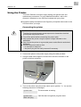
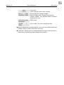
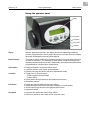
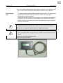
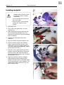
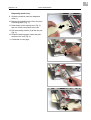
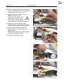
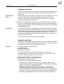
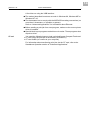
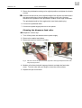
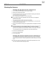
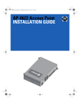
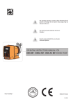
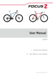
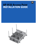
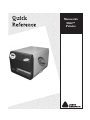
Quick Reference TC9864QR Rev. AA 6/08 Monarch® 9864™ Printer ©2008 by Avery Dennison Corp. All rights reserved. Each product and program carries a respective written warranty, the only warranty on which the customer can rely. Avery Dennison reserves the right to make changes in the product, the programs, and their availability at any time and without notice. Although Avery Dennison has made every effort to provide complete and accurate information in this manual, Avery Dennison shall not be liable for any omissions or inaccuracies. Any update will be incorporated in a later edition of this manual. 2008 Avery Dennison Corporation. All rights reserved. No part of this publication may be reproduced, transmitted, stored in a retrieval system, or translated into any language in any form by any means, without the prior written permission of Avery Dennison Corporation. WARNING This equipment has been tested and found to comply with the limits for a Class A digital device, pursuant to Part 15 of the FCC Rules. These limits are designed to provide reasonable protection against harmful interference when the equipment is operated in a commercial environment. This equipment generates, uses, and can radiate radio frequency energy and, if not installed and used in accordance with the instruction manual, may cause harmful interference to radio communications. Operation of this equipment in a residential area is likely to cause harmful interference in which case the user will be required to correct the interference at his own expense. CANADIAN D.O.C. WARNING This digital apparatus does not exceed the Class A limits for radio noise emissions from digital apparatus set out in the Radio Interference Regulations of the Canadian Department of Communications. Le présent appareil numérique n'émet pas de bruits radioélectriques dépassant les limites applicables aux appareils numériques de la classe A prescrites dans le Réglement sur le brouillage radioélectrique édicte par le ministère des Communications du Canada. Trademarks Monarch and 9864 are trademarks of Paxar Americas, Inc. Avery Dennison® is a trademark of Avery Dennison Corp. Avery Dennison Printer Systems Division 170 Monarch Lane Miamisburg, OH 45342 Visit www.monarch.com for sales, service, supplies, information, and telephone numbers for our International locations. TOLL FREE: 1-800-543-6650 (U.S.A.) 1-800-363-7525 (Canada) 1 06/08 Rev. AA QUICK REFERENCE Getting Started 9864 Using the Printer This Quick Reference contains supply loading and general care and maintenance procedures. For more detailed information, refer to the Operator’s Handbook on the CD-Rom included with your printer. « Review the safety information in the Regulatory Compliance document on the CD-Rom before you begin. Connecting the printer WARNING! Touching live electrical parts causes exposure to hazardous electrical currents and may lead to burns. « Turn off the printer before connecting the power cable. « Only operate the printer using the system voltage indicated on the nameplate. « Only connect the printer to a grounded power socket fitted to authorized standards. « Connect the power cable so that – no one trips or steps on it – the power plug can be easily removed if necessary. 1. Turn the printer power switch to “0” (off). 2. Connect the printer to the power supply using the cable provided. 3. Using the data cable supplied, connect the Centronics interface on the printer to the host computer. A [1] B Sockets for the Centronics cable (A) and power cable (B) on a 9864. 4. Turn on the printer using the power switch (set to position “1”). You see the following sequence of messages: System start... The boot loader is starting. System start... Start user prog Valid firmware recognized, program starts. 2 06/08 Rev. AA QUICK REFERENCE Getting Started 9864 9864 V 4.10 Printer type Version number of the printer firmware Memory: 64 MB Flashcard: 32 MB Internal RAM (for example: 64 MB) Optional RAM on the Compact Flash card (for example: 32 MB) – only displayed when a Compact Flash card is in use. OFFLINE 0 JOBS Initialisation Offline mode ONLINE JOBS Online mode. The unit is ready for printing. 0 ¯ When the parameter SYSTEM PARAMETER > Active Mode is set to Offline, the printer switches directly to offline mode when turned on. ¯ CAUTION! - Wait at least 10 seconds between turning the printer off and on, because any modified parameter settings are not saved. 3 06/08 Rev. AA QUICK REFERENCE Getting Started 9864 Using the operator panel Display Prog button Feed button Online button Cut button [2] Operator panel Display With 32 digits and two lines, the display shows the operating conditions (modes) for parameters, values, status and errors. You can select the display language. Backlighting ensures good legibility. Button functions The buttons offer a multitude of operating functions. A logical menu structure is used for operation. The meaning of each button varies according to the operating mode and the menu item. Additionally, special functions have been programmed for certain button combinations. Online button y Switches between online and offline mode. y Confirms entries, menu items and messages. y Selects print jobs and enters values in standalone mode. Cut button y Triggers a cut. Requirements: – Cutter installed and activated. – Printer offline. y Scrolls down through the menu and selects menu items. y Decreases values. Feed button y y y y Prog button y Accesses the parameter menu when offline. y Returns to previous menu item and/or exits the menu. Feeds the material when the device is offline. Starts printing once the feed has been stopped (in online mode). Scrolls up through the menu and selects menu items. Increases values. 4 06/08 Rev. AA QUICK REFERENCE Getting Started 9864 y For more detailed descriptions of the button functions, see “Creating a print job” or refer to Info-Printouts and Parameters section on the CD-Rom. Remote operator panel The printer can be equipped with a remote operator panel. The printer must provide the appropriate optional connector. Refer to the Operator’s Handbook for more information. The button functions are the same as those on the standard operator panel. Exception: The on/off switch is not available at the remote control panel. With the remote control panel connected, both panels are active and show the same information. CAUTION! Using both operator panels at the same time can cause malfunctions. « Use only one operator panel at a time to operate the printer. CAUTION! If the connection cable is longer than 2.5 m, EMC-caused disturbances can occur. « Only use the factory-installed cable. « Do not extend the cable. [3] Remote operator panel (article number 160005) 5 06/08 Rev. AA QUICK REFERENCE 9864 Loading material 1 CAUTION! Rotating axles! These can pull in and tear off hair, clothing and jewelry. – Do not operate the printer with the cover open! – Keep long hair, loose clothing, jewelry etc. away from the printer! 1. Open the cover. 2. Pull off the outer guide disk (1) of the unwinder (2). 2 3. Place the material on the unwinder with the corresponding adapter rings. The material roll should turn counter-clockwise when unwinding. 4. Replace the outer guide disk of the unwinder. 5. Lay the material around the dancer arm. 6. Set the material guide to the material width. Loosen the thumb screw on the underside of the front material guide (3). Push the material guide sideways. Tighten the thumb screw (Fig. 2). 3 7. Press the red or green opener (4) of the intake to raise the pad rollers. Press and hold the opener and push the material through the material guide until it is below the printhead (Fig. 3). 8. Align the material so that it is straight. While holding down the loading lever, position the pad rollers so that both rollers (5) sit symmetrically on the material. (The printhead has been removed in Fig. 4 to allow a better view). 4 6 06/08 Rev. AA QUICK REFERENCE 9864 Dispensing model only: 1 9. Guide the material under the dispenser roller (1). 10. Remove the labels from the first 10 inches of backing paper (Fig. 1). 11. Press down on the locking lever (Fig. 2) and turn it half a revolution to the rear. 12. Pull the drawing module (2) all the way out (Fig. 3). 13. Guide the backing paper under the print module to the rear (Fig. 4). P Continued on next page. 2 3 4 7 06/08 Rev. AA QUICK REFERENCE 9864 14. Guide the backing paper around the feed roller (1) and guide pins (2) of the drawing module to form an S shape (Fig. 1). 1 15. Replace the drawing module (Fig. 2). ¯ When replacing, the locking lever must point to the right (half a revolution open). Do not lock it until the drawing module has been pushed in all the way! 16. Wrap the end of the backing paper clockwise around the takeup reel (3) and secure it with the clip (4) (Figs. 3 and 4). 17. Position the block bearing and the pressure roller (5) in the middle of the backing paper. 2 ¯ This keeps the backing paper in place around the dispensing edge! 18. Lock the locking lever (Fig. 4). 3 4 8 06/08 Rev. AA QUICK REFERENCE 9864 Loading fan-folded material 1. Set the outer disk of the material unwinder to the material width. 2. Pull the material through the inlet opening (1) to the material guide printing side up. 3. See “Loading material” to continue. [1] Pull the fan-folded material through the inlet opening in the rear side and see “Loading material” to continue. 9 06/08 Rev. AA QUICK REFERENCE 9864 Changing material 1 Follow these instructions to replace the material roll. ¯ The printer must be turned on; otherwise, the printhead presses on the material. 9864 1. Set the printer to offline mode and open the cover. 2. To remove the material, press and hold the opener while pulling the material back towards the roll (Fig. 2). 2 9864 dispenser 1. Set the printer to offline mode and open the cover. 2. Tear the backing paper off (2), pull out the clip (Fig. 3) and remove the wound up backing paper (Fig. 4). 3. Open the shutter (3) and pull out the remaining backing paper towards the dispensing edge. 4. To remove the material, press and hold the opener while pulling the material back towards the roll (Fig. 2). ¯ You can also move the material backwards by pressing the Online+Cut keys while in offline mode. 3 10 06/08 Rev. AA QUICK REFERENCE 9864 Loading a ribbon 1 1. Turn on the printer. 2. Open the cover. 3. Place the roll of ribbon on the ribbon unwind reel (1) so that it unwinds counterclockwise. 4. Place the empty ribbon core on the rewind reel (2). 5. Lead the end of the protective ribbon (yellow here) under the ribbon deflector (3) and printhead (4). 6. Pull the protective ribbon upwards and lay it over the ribbon roller (5). 2 7. Lead the protective ribbon under the rewind reel (2) and secure it on the empty ribbon core using the self-adhesive strip (6) (Fig. 3). ¯ With many ribbons, the protective ribbon (shown in yellow) is followed by a strip of cleaning ribbon (7) which removes contamination from the printhead. The material must be loaded as described to clean effectively! 3 8. The ribbon should be straight and creasefree. Turn the ribbon unwind reel to tighten the ribbon and eliminate slack. 4 11 06/08 Rev. AA QUICK REFERENCE 9864 Settings for all printers Ribbon tension The tension of the ribbon unwind reel (1) and ribbon rewind reel (2) can be set using the red plastic hexagons on the ribbon reels. If these are turned clockwise, the tension increases (Fig. 1: dispenser version). Default settings The default settings covers a wide range of ribbon widths, but you may need to adjust the settings for very narrow or very wide ribbons. Setting During feeding, the ribbon must run evenly (no creases) for the entire length between the reels. Use the following guidelines: If the ribbon is loose, creased, or is loosely wound on the rewind reel. « Increase the unwind/rewind tension (Turn the red hex nut clockwise). If the ribbon visibly stretches or tears during printing. The ribbon is not loaded correctly. « Decrease the unwind/rewind tension (Turn the red hex nut counter-clockwise). 1 12 06/08 Rev. AA QUICK REFERENCE 9864 Material parameters The following three parameters are used to set the material properties: Parameter Function PRINT PARAMETER > material type Sets the material type (punched or continuous) PRINT PARAMETER > material length Sets the material length PRINT PARAMETER > material width Sets the material width SYSTEM PARAMETER > light sens. type Sets the sensor type (reflex or transmission) based on the material (marks or perforations) [Tab. 1] Important parameters for setting material properties P For more information on setting parameters, see “Operating the parameter menu” in the topic section “Info printouts and parameters.” 13 06/08 Rev. AA QUICK REFERENCE 9864 Creating a print job There are two ways of creating a print job: by using the Microsoft® Windows® printer driver for the 9864, or by creating a text file using Easy Plug print commands. Windows printer driver 9864 printer drivers are available for different versions of Windows. You can print from nearly every Windows application using the printer drivers. However, functionality is strongly dependent on the choice of software. Label layout programs are preferred. ¯ The driver’s help function explains how to use the printer driver. The help function of your Windows operating system tells you how to install the driver. Printer drivers for different versions of Windows are available on our Web site (www.monarch.com). Command file You can write a sequence of commands in a text file and send it to the printer. Use any text editor and the MS-DOS Copy command. Easy Plug provides a special command language to program print jobs. However, writing a print job in text file format requires some programming knowledge. You cannot preview the resulting printout on the screen. Instead, print a test print to see a copy of the finished result. For more information refer to the Easy Plug Manual. Sending a print job The printer processes print jobs once the jobs are sent to the printer’s RAM. This can be accomplished with a direct transfer from your computer using a data cable or saving it to a Compact Flash (CF) card. Data cable The print job can be transferred with y the serial interface, y the parallel interface, y the Ethernet connection. To transfer data with the serial or parallel interface, connect the corresponding ports on the host computer and the printer. Use the DOS window to send the print job file to the interface. y Serial interface (COM1): copy testjob.txt com1 y Parallel interface (LPT1): copy testjob.txt lpt1 y USB interface / Ethernet interface: copy testjob.txt \\computername\sharename. – computername = Name of the computer (for example, “Warehouse”). In Windows XP this can be found under START > SETTINGS > CONTROL PANEL > SYSTEM > COMPUTER NAME. – sharename = enter the name found under START > SETTINGS > PRINTERS AND FAXES after clicking on a printer symbol and rightclicking PROPERTIES > SHARE (in Windows XP). The sharename stands for a printer, which is connected to a certain port. This is the USB port for transferring with USB and the TCP/IP port for transferring by Ethernet. 14 06/08 Rev. AA QUICK REFERENCE 9864 A few hints on using the USB interface: ¯ The method described here does not work in Windows 98, Windows ME or Windows NT 4.0. ¯ The sharename has to comply with the MS-DOS formatting conventions (no more than 8 characters, no symbols or spaces). Refer to “Advanced Applications” for information about Ethernet. ¯ Before sending a print job from a text program, make sure the correct printer driver is installed. ¯ Special label layout programs make this much easier. These programs also require a driver. CF card You need the following items to load a print job from a Compact Flash card: y CF card (copy the print job to the directory \FORMATS) y CF card reader (to connect to your computer) For information about transferring print jobs via the CF card, refer to the Standalone Operation section of “Advanced Applications.” 15 06/08 Rev. AA QUICK REFERENCE 9864 Starting to print Settings for the material type The parameter settings below describe setting up the label material. When printing from a layout program, these settings are usually provided automatically by the printer driver. For your first test prints, you need to configure them manually. Material type y The label material is endless (continuous) which means that it contains no punches/perforations, breaks or reflex marks that could be recognized by the punch (die cut) sensor: « Set the PRINT PARAMETER > Material Type to endless. y The label material contains punches/perforations, breaks or reflex marks that can be recognized by the punch sensor (so-called “punched” material): « Set the PRINT PARAMETER > Material Type to “Punched.” Material length « Set the PRINT PARAMETER > Material Length to the length of the material (in mm). Material width « Set the PRINT PARAMETER > Material Width to the width of the material (in mm). Only for punched/perforated (die cut) material: Type of punch y Label material with breaks or punches: « Set the SYSTEM PARAMETER > Sensor Type to Punched. y Label material with reflex marks: « Set the SYSTEM PARAMETER > Sensor Type to Reflex. For more information on setting parameters: refer to “Info-Printouts and Parameters.” Printing the status report To test the printer, print a status report. The width of the status printout can be set to 4 inches (100 mm) or 2 inches (50 mm). This should match the width of the label material used. The length of the printout is 8 inches (200 mm). 4-inch width (100 mm) 2-inch width (50 mm) « Navigate to INFO PRINTOUT > Printer Status. The printout (two 8-inch labels) lists all of the printer’s current parameter settings. « Set the SYSTEM PARAMETER > Print Info Mode to “Compact right.” « Navigate to INFO PRINTOUT > Printer Status. This printout contains the same information as the 4-inch printout, compressed to a 2-inch width. 16 06/08 Rev. AA QUICK REFERENCE 9864 Density To make the print darker, increase the print density as follows: 1. Press Esc while in online mode. You see Print contrast 60% 2. Press Cut/Feed to increase or decrease the heat energy of the printhead (in %). The heat energy should be kept as low as possible while retaining an acceptable printing result. A high level of heat energy reduces the life span of the printhead. 17 06/08 Rev. AA QUICK REFERENCE 9864 Care & Maintenance Regular maintenance is required to keep the printer operating properly. Safety WARNING! Maintenance and cleaning may result in hazerdous situations. Accidents can occur if the appropriate safety instructions are not followed! Turn off the printer and disconnect the power supply before any cleaning or maintenance work! Be careful when cleaning the cutter! Troubleshooting Status When an error occurs, read the messages first and refer to the documentation for more information. Call servicing If you need to call Technical Support, have your printer’s model and serial numbers ready. To order spare parts, call Technical Support. Notes on cleaning Frequency of care Frequent maintenance and cleaning is required to make sure the printer is operating safely. The rate and frequency at which you print determines how often you must clean the printer. Regularly check the printhead and feed roller for paper or adhesive buildup. CAUTION! - Do not use any cleaning agents which could damage or destroy the coating surfaces, labelling, display, electrical components etc. CAUTION! - Avoid acidic and alkaline solutions. Do not use any cleaning agents that are abrasive or damaging to plastics. Cleaning the Printhead You may need to clean the printhead when you see voids or streaks in the printing or notice uneven printing. 1. Turn off the printer and disconnect the power supply. 2. Remove the material and ribbon. 3. Unscrew the two thumb screws on the printhead mounting and rotate the entire printhead mounting upwards. CAUTION! - The printhead is sensitive to static electricity, which can damage the printhead or reduce its life. Ground yourself by touching a metal object, such as the printer’s metal base, before touching the printhead. Do not use sharp or metal objects to clean the printhead or touch the printhead with your fingers. 18 06/08 Rev. AA QUICK REFERENCE 9864 ¯ The printhead does not need to be removed. Mark the position of the printhead on the axle, if it is not flushed against the inner or outer plastic ring. 4. Moisten a lint-free cloth with isopropyl alcohol and wipe the printhead clean. You can also use a cleaning pen (114226). Fig. 1 Cleaning the printhead – the printhead does not need to be removed (Fig: Dispenser version). 5. Return the printhead mounting to its original position and tighten the thumb screws. ¯ Press the thumb screw on the tapered edge of the square axle to ensure the exact positioning of the printhead mounting on the axle. Also pay attention to the position of the printhead in relation to the edge of the label. The printhead should be flush against the inner black plastic plug. 6. Connect the printhead cable before turning on the printer. 19 06/08 Rev. AA QUICK REFERENCE 9864 Cleaning the Rollers Cleaning the print roller Clean the print roller when you see adhesive buildup or dirt on the roller. 1. Turn off the printer and disconnect the power supply. 2. Remove the material and ribbon. 3. Dispenser version only: Remove the dispensing edge to access the print roller by removing both holding screws (1). Fig. 2 When using a 64xx dispenser, remove the dispensing edge to access the print roller. 1 1 4. Unscrew the two thumb screws on the printhead mounting and rotate the entire printhead mounting upwards. P See “Cleaning the Printhead” for more information. ¯ If the printhead needs to be removed, mark the position of the printhead on the axle, if it is not flushed against the inner or outer plastic ring. 5. Moisten a cloth with isopropyl alcohol and wipe the roller clean. Turn the print roller with your finger to clean the entire surface. Fig. 3 Rotate the printhead upwards before cleaning it. 20 06/08 Rev. AA QUICK REFERENCE 9864 ¯ CAUTION! - Only clean the print roller with a lint-free cloth. Do not use sharp objects to clean the rollers! 6. Return the printhead mounting to its original position and tighten the thumb screws. ¯ Press the thumb screw on the tapered edge of the square axle and ensure the exact positioning of the printhead mounting on the axle. Also pay attention to the position of the printhead in relation to the edge of the label. The printhead should be flush against the inner black plastic plug. 7. Connect the printhead cable before turning on the printer. Cleaning the feed roller Clean the feed roller when you adhesive buildup or dirt on the roller. 1. Turn off the printer and disconnect the power supply. 2. Remove the material and ribbon. 3. Remove the printhead. 4. Moisten a lint-free cloth with isopropyl alcohol and wipe the feed roller clean. Turn the roller with your finger to make sure it is clean all the way around. ¯ Shift the front material guiding (1) and the contact pressure rollers (2) for better access to the roller. Fig. 4 To clean the feed roller, remove the printhead and shift material guiding (1) and set the contact pressure rollers (2) aside. 2 1 21 06/08 Rev. AA QUICK REFERENCE 9864 5. Return the printhead mounting to its original position and tighten the thumb screws. ¯ Press the thumb screw on the tapered edge of the square axle and ensure the exact positioning of the printhead mounting on the axle. Also pay attention to the position of the printhead in relation to the edge of the label. The printhead should be flush against the inner black plastic plug. 6. Connect the printhead cable. 7. Connect the power supply and turn on the printer. Cleaning the dispenser-feed roller ¯ Dispensor version only! 1. Turn off the printer and disconnect the power supply. 2. Remove he material and ribbon. 3. Remove the pull-out module (left side). Fig. 5 Left side: remove the pull-out module; right side: cleaning the dispenser-feed-roller using isopropyl alcohol. 4. Moisten a lint-free cloth with isopropyl alcohol and wipe the feed roller clean. Turn the roller with your finger to clean the entire surface. 5. Replace the pull-out module. 22 06/08 Rev. AA QUICK REFERENCE 9864 Cleaning the Sensors Cleaning the gap photoelectric switch/sensor 1. Turn off the printer and disconnect the power supply. 2. Remove the material and ribbon. 3. Unscrew the two thumb screws on the printhead mounting and rotate the entire printhead mounting upwards. P See “Cleaning the Printhead” for more information. ¯ If you need to remove the printhead, mark the position of an adjusted printhead on the axle. The gap photoelectric switch can now be accessed. 4. Clean the gap photoelectric switch with compressed air or a lint-free cloth moistened with isopropyl alcohol. 5. Return the printhead mounting to its original position and tighten the thumb screws. ¯ Press the thumb screw on the tapered edge of the square axle and ensure the exact positioning of the printhead mounting on the axle. Also pay attention to the position of the printhead in relation to the edge of the label. The printhead should be flush against the inner black plastic plug. 6. Connect the printhead cable. 7. Connect the power supply. 8. Turn on the printer. Cleaning the material end photoelectric switch/sensor The material end photoelectric switch is located on the inner red material feed on the print module. Clean the photoelectric switch when you see dust on it. £ Clean the material end photoelectric switch with compressed air or a lintfree cloth moistened with isopropyl alcohol. 23 06/08 Rev. AA QUICK REFERENCE 9864 Specifications Printer - 4-inch Height: 12.0 inches (305 mm) Width: 12.8 inches (320 mm) Depth: 21.6 inches (540 mm) with cutter 19.6 (490 mm) with dispenser (peel) Weight: 48 lb. (22 kg) with cutter 52 lb. (24 kg) with dispenser (peel) Print Width: 4.3 inches (107 mm) Print Speed: 2 - 16 ips (50 - 406 mms) Printer - 5-inch Height: 12.0 inches (305 mm) Width: 12.8 inches (320 mm) Depth: 21.6 inches (540 mm) with cutter 19.6 (490 mm) with dispenser (peel) Weight: 48 lb. (22 kg) with cutter 52 lb. (24 kg) with dispenser (peel) Print Width: 5.1 inches (128 mm) Print Speed: 2 - 16 ips (50 - 406 mms) Printer - 6-inch Height: 12.0 inches (305 mm) Width: 14.0 inches (350 mm) Depth: 21.6 inches (540 mm) with cutter 19.6 (490 mm) with dispenser (peel) Weight: 51 lb. (23 kg) with cutter 54 lb. (25 kg) with dispenser (peel) Print Width: 6.3 inches (160 mm) Print Speed: 2 - 14 ips (50 - 359 mms) 24 06/08 Rev. AA QUICK REFERENCE 9864 Printer - 8-inch Height: 12.0 inches (305 mm) Width: 18.0 inches (450 mm) Depth: 21.6 (540 mm) with cutter 19.6 (490 mm) with dispenser (peel) Weight: 61 lb. (27.5 kg) with cutter 65 lb. (29.5 kg) with dispenser (peel) Print Width: 8.4 inches (213 mm) Print Speed: 2 - 9 ips (50 - 229 mms) Printer Operation Limits: 41° to 95°F (5° to 35°C) Storage: -4° to 158°F (-20° to 70°C) Humidity: 45% to 75% non-condensing Printhead: 300 dpi (12 dots per mm) Printing Method: Thermal Transfer (ribbon) or Thermal Direct Non-Print Zone: A 0.04-inch non-print zone exists on the leading edge and the right edge of the label. 25 06/08 Rev. AA QUICK REFERENCE 9864 Supplies (Material) 4-Inch Width: 1.0 - 6.2 inches (25.4 to 154 mm) 1.0 - 5.6 inches (25.4 - 140 mm) with dispenser 5-Inch Width: 1.0 - 6.2 inches (25.4 to 154 mm) 1.0 - 5.6 inches (25.4 - 140 mm) with dispenser 6-Inch Width: 1.2 - 7.3 inches (30.2 - 185 mm) 1.2 - 6.8 inches (30.2 - 172 mm) with dispenser 8-Inch Width: 4.0 - 10.0 inches (100 - 254 mm) 4.0 - 9.5 inches (100 - 241 mm) with dispenser Min. Length: 0.2 inches (5 mm) 0.4 inches (10 mm) with dispenser Roll Diameter: 8.3 inches (210 mm) maximum outer diameters 1.5, 3.0, or 4.0 inches (38, 76, or 102 mm) inner diameters Ribbon (Foil) 4-Inch Width: 1.2 - 5.3 inches (30 to 132 mm) 1.2 - 5.6 inches (30 - 140 mm) with dispenser 5-Inch Width: 1.2 - 5.3 inches (30 to 132 mm) 1.2 - 5.6 inches (30 - 140 mm) with dispenser 6-Inch Width: 1.2 to 6.5 inches (30 to 164 mm) 1.2 to 6.8 inches (30 to 172 mm) with dispenser 8-Inch Width: 1.6 to 8.6 inches (40 to 217 mm) 1.6 to 9.6 inches (40 to 241 mm) with dispenser Roll Diameter: 3.6 inches (90 mm) maximum outer diameter 1.0 inches (25.4 mm) inner diameter