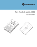
1
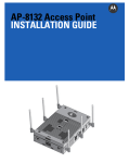
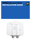
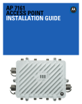
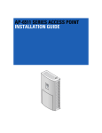
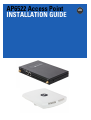
AP6522 Access Point
INSTALLATION GUIDE
2
AP6522 Access Point
MOTOROLA SOLUTIONS and the Stylized M Logo are registered in the US Patent & Trademark Office. © Motorola Solutions,
Inc. 2012. All rights reserved.
Installation Guide
1.0 Introduction . . . . . . . . . . . . . . . . . . . . . . . . . . . . . . . . . . . . . . . . . . . . . . . . . . . . . . 4
1.1 Document Conventions . . . . . . . . . . . . . . . . . . . . . . . . . . . . . . . . . . . . . . . . . . . . . . . 4
1.2 Warnings . . . . . . . . . . . . . . . . . . . . . . . . . . . . . . . . . . . . . . . . . . . . . . . . . . . . . . . . . . 5
1.3 Site Preparation . . . . . . . . . . . . . . . . . . . . . . . . . . . . . . . . . . . . . . . . . . . . . . . . . . . . 5
1.4 AP6522 Package Contents. . . . . . . . . . . . . . . . . . . . . . . . . . . . . . . . . . . . . . . . . . . . . 5
2.0 Hardware Installation . . . . . . . . . . . . . . . . . . . . . . . . . . . . . . . . . . . . . . . . . . . . . . 7
2.1 Installation Instructions . . . . . . . . . . . . . . . . . . . . . . . . . . . . . . . . . . . . . . . . . . . . . . . 7
2.2 Precautions . . . . . . . . . . . . . . . . . . . . . . . . . . . . . . . . . . . . . . . . . . . . . . . . . . . . . . . . 8
2.3 Access Point Placement. . . . . . . . . . . . . . . . . . . . . . . . . . . . . . . . . . . . . . . . . . . . . . . 8
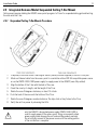
2.4 Integrated Antenna Model Wall Mount Instructions . . . . . . . . . . . . . . . . . . . . . . . . 8
2.5 Integrated Antenna Model Suspended Ceiling T-Bar Mount . . . . . . . . . . . . . . . . . 11
2.6 External Antenna Model Wall Mount Instructions . . . . . . . . . . . . . . . . . . . . . . . . . 12
2.7 External Antenna Model Suspended Ceiling T-Bar Mount . . . . . . . . . . . . . . . . . . . 15
2.8 External Antenna Suspended Ceiling Tile (Plenum) Mount . . . . . . . . . . . . . . . . . . 17
2.9 AP6522 External Antenna Model Antenna Options . . . . . . . . . . . . . . . . . . . . . . . . 18
2.10 LED Indicators . . . . . . . . . . . . . . . . . . . . . . . . . . . . . . . . . . . . . . . . . . . . . . . . . . . . 20
3.0 Initial Access Point Configuration . . . . . . . . . . . . . . . . . . . . . . . . . . . . . . . . . . 22
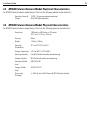
4.0 Specifications. . . . . . . . . . . . . . . . . . . . . . . . . . . . . . . . . . . . . . . . . . . . . . . . . . . . 38
4.1 AP6522 Integrated Antenna Model Electrical Characteristics . . . . . . . . . . . . . . . . 38
4.2 AP6522 Integrated Antenna Model Physical Characteristics . . . . . . . . . . . . . . . . . 38
4.3 AP6522 External Antenna Model Electrical Characteristics . . . . . . . . . . . . . . . . . . 39
4.4 AP6522 External Antenna Model Physical Characteristics. . . . . . . . . . . . . . . . . . . 39
4.5 Radio Characteristics. . . . . . . . . . . . . . . . . . . . . . . . . . . . . . . . . . . . . . . . . . . . . . . . 40
5.0 Regulatory Information . . . . . . . . . . . . . . . . . . . . . . . . . . . . . . . . . . . . . . . . . . . . 41
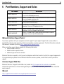
6.0 Part Numbers, Support and Sales . . . . . . . . . . . . . . . . . . . . . . . . . . . . . . . . . . . 49
7.0 Motorola Solutions, Inc. End-User License Agreement . . . . . . . . . . . . . . . . 50
8.0 AP6522 Access Point China ROHS Compliance . . . . . . . . . . . . . . . . . . . . . . 53
3
4
AP6522 Access Point
1 Introduction
The AP6522 access point, a component of the Motorola Solutions wireless controller system, links wireless
802.11abgn devices to the controller, enabling the growth of your wireless network with a cost effective
alternative to standard access points. The AP6522 access point provides multiple deployment options.
The AP6522 access point receives all power and transfers data through the same CAT-5 or better Ethernet cable.
An 802.3af Ethernet switch or power supply (specifically rated for the AP6522) is required (Part No.
PWRS-14000-148R).
An AP6522 model access point uses WiNG 5 software as its onboard operating system. The access point’s unique
WiNG 5 software enables the access point to function as either a Virtual Controller AP capable of adopting and
managing up to 24 additional AP6522 access points, a Standalone access point or a Dependent mode access point
managed by its connected controller.
If new to Motorola Solutions access point technology, refer to the WiNG Access Point System Reference Guide to
familiarize yourself with access point technology and the feature set supported by the WiNG operating system.
The guide is available, at http://supportcentral.motorola.com/support/product/manuals.do.
The AP6522 access point is approved under MODEL: AP-0622.
This document is written for the qualified network device installer.
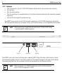
1.1 Document Conventions
The following graphical alerts are used in this document to indicate notable situations:
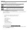
NOTE
!
Tips, hints, or special requirements that you should take note of.
CAUTION
Care is required. Disregarding a caution can result in data loss or
equipment malfunction.
WARNING! Indicates a condition or procedure that could result in personal injury or
equipment damage.
Installation Guide
5
1.2 Warnings
•
•
•
•
•
Read all installation instructions and site survey reports, and verify correct equipment installation before
connecting the access point.
Remove jewelry and watches before installing this equipment.
Verify the unit is grounded before connecting it to the power source.
Verify any device connected to this unit is properly wired and grounded.
Verify there is adequate ventilation around the device, and that ambient temperatures meet equipment
operation specifications.
1.3 Site Preparation
• Consult your site survey and network analysis reports to determine specific equipment placement, power
drops, and so on.
• Assign installation responsibility to the appropriate personnel.
• Identify and document where all installed components are located.
• Ensure adequate, dust-free ventilation to all installed equipment.
• Identify and prepare Ethernet and console port connections.
• Verify cable lengths are within the maximum allowable distances for optimal signal transmission.
1.4 Package Contents
An AP6522 access point is available in integrated antenna and external antenna models. Contents differ
depending on the model ordered.
1.4.1 External Antenna Model Package Contents
•
•
•
•
AP6522 access point with external antenna connectors (Plenum Rated)
2 customer installed mounting lugs
4 mounting lug retaining screws
AP6522 Installation Guide (This Guide)
1.4.2 Internal Antenna Model Package Contents
•
•
AP6522 access point with internal antennas
AP6522 Installation Guide (This Guide)
6
AP6522 Access Point
1.4.3 Features
•
•
•
•
2 RJ-45 connectors, one for 10/100/1000 Ethernet and the other for the serial/console connector
LED indicators
Slots for wall mounting
Clips for mounting on a suspended ceiling T-bar (internal antenna model only) with separately orderable
accessories
• Lock port for Kensington® style Security Lock
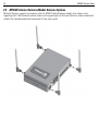
The AP6522 access point has one RJ-45 connector supporting an 10/100/1000 Ethernet port and accepts
802.3af-compliant power from an external source. The illustration below is of an integrated antenna model.
NOTE
When operating in a Gigabit Ethernet environment, CAT-5e or CAT-6 cable
is recommended for Gigabit operation.
DC12V
GE1/PoE
Console
The AP6522 access point comes with dual radios supporting 802.11abgn. The access point contains runtime
firmware which enables the unit to boot after a power up. The runtime firmware on the access point and the
firmware downloaded from the connected controller can be updated via the Ethernet interface.
NOTE
When connecting to an AP6522 model access point, note that the baud
rate is 115,200 as opposed to 19,200.
Installation Guide
2
7
Hardware Installation
2.1 Installation Instructions
The AP6522 access point mounts either on a wall (with customer supplied M4 x 25 pan head screws and wall
anchor - or equivalent) or on a suspended ceiling T-bar. If deploying an external antenna model AP6522 on a
suspended ceiling T-bar, access point mounting kit (Part No. KT-135628-01) is required. An AP6522 is not designed
for mounting on a desk.
To prepare for the installation:
1. Match the model number on the purchase order with the model numbers in the packing list and on the
case of the access point.
2. Verify the contents of the box include the intended AP6522 access point, and the included hardware
matches the package contents on page 5.
Part Number
Description
AP-6522-66030-US
Dual 802.11n radio AP6522. Plastic enclosure with internal antennas.
For use in the US deployments only.
AP-6522-66030-EU
Dual 802.11n radio AP6522. Plastic enclosure with internal antennas.
For use in European countries only.
AP-6522-66030-WR
Dual 802.11n radio AP6522. Plastic enclosure with internal antennas.
For use in non-US countries only.
AP-6522-66040-US
Dual 802.11n radio AP6522. Metal enclosure with external antenna
connectors. For use in US deployments only.
AP-6522-66040-EU
Dual 802.11n radio AP6522. Metal enclosure with external antenna
connectors. For use in European countries only.
AP-6522-66040-WR
Dual 802.11n radio AP6522. Metal enclosure with external antenna
connectors. For use in non-US countries only.
3. Review site survey and network analysis reports to determine the location and mounting position for the
AP6522 access point.
4. Connect a CAT-5 or better Ethernet cable to a compatible 802.3af power source and run the cable to the
installation site. Ensure there is sufficient slack on the cable to perform the installation steps.
NOTE
When operating in a Gigabit Ethernet environment, CAT-5e or CAT-6 cable
is recommended for Gigabit operation.
8
AP6522 Access Point
2.2 Precautions
Before installing an AP6522 model Access Point, verify the following:
•
•
•
If a DC power supply is used, ensure it’s the approved power supply for the AP6522 (PWRS-1400-148R).
Motorola Solutions recommends you do not to install the AP6522 in wet or dusty areas.
Verify the environment has a continuous temperature range between 0° C to 40° C.
2.3 Access Point Placement
For optimal performance, install the access point away from transformers, heavy-duty motors, fluorescent lights,
microwave ovens, refrigerators and other industrial equipment. Signal loss can occur when metal, concrete, walls
or floors block transmission. Install the access point in an open area or add access points as needed to improve
coverage.
Antenna coverage is analogous to lighting. Users might find an area lit from far away to be not bright enough. An
area lit sharply might minimize coverage and create dark areas. Uniform antenna placement in an area (like even
placement of a light bulb) provides even, efficient coverage.
Place the access point using the following guidelines:
•
•
Install the access point at an ideal height of 10 feet from the ground.
Orient the access point antennas vertically for best reception (applies to external antenna models only).
To maximize the access point’s radio coverage area, Motorola Solutions recommends conducting a site survey to
define and document radio interference obstacles before installing the access point.
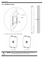
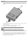
2.4 Integrated Antenna Model Wall Mount Instructions
Wall mounting requires hanging the AP6522 along its width or length using the two slots on the bottom of the unit.
The AP6522 can be mounted on to any plaster, wood, or cement wall surface using customer supplied screw
hardware (M3.5 x 0.6 x 20 mm- or equivalent).
2.4.1 Wall Mount Hardware
•
•
•
Two wide-shoulder Phillips pan head self-tapping screws (customer supplied)
Two wall anchors (customer supplied)
Security cable (optional)
NOTE
The following screws are recommended: (ANSI Standard) #6-18 X
0.875in. Type A or AB Self-Tapping Screw, or (ANSI Standard Metric)
M3.5 X 0.6 X 20mm Type D Self-Tapping Screw.
Installation Guide
9
2.4.2 Wall Mount Procedure
1. Orient the case on the wall by its width or length.
!
CAUTION
To ensure proper operation of an AP6522 access point, ensure it is
mounted in the correct orientation as shown above.
10
AP6522 Access Point
2. Mark two points (for drill holes) 4.08 inches (103.7 mm) apart on a horizontal line.
3. At each point, drill a hole in the wall, insert an anchor, screw into the anchor the wall mounting screw and
stop when there is 1mm between the screw head and the wall.
NOTE
When pre-drilling a hole the recommended hole size is 2.8mm (0.11in.).
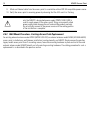
4. If required, install and attach a Kensington security cable (customer supplied) to the unit’s lock port.
5. Attach an Ethernet cable from the access point to a controller with an 802.3af-compatible power source
or use the PWRS-14000-148R power supply to supply power to the AP6522 (once fully cabled).
6. Place the middle of each of the case’s mount slots over the screw heads.
7. Slide the case down along the mounting surface to hang the mount slots on the screw heads.
8. Verify the unit has power by observing that the LEDs are lit or flashing.
CAUTION
!
If not using a 802.3af capable controller to power the AP6522, ensure
only the AP6522’s designated power supply (PWRS-14000-148R) is
used to supply power to the access point. Using an incorrectly rated
power supply could damage the unit and void the product warranty.
Do not actually connect to the power source until the cabling portion
of the installation is complete.
Installation Guide
11
2.5 Integrated Antenna Model Suspended Ceiling T-Bar Mount
Ceiling mount requires holding the AP6522 access point up against a T-bar of a suspended ceiling grid and twisting
the case onto the T-bar.
2.5.1 Suspended Ceiling T-Bar Mount Procedure
1. If required, install and attach a Kensington security cable (customer supplied) to the unit’s lock port.
2. Attach an Ethernet cable from the access point to a controller with an 802.3af compatible power source
or use the PWRS-14000-148R power supply to supply power to the AP6522 (once fully cabled).
3. Align the bottom of the T-bar with the back of the case.
4. Orient the case by its length, and the length of the T-bar.
5. Rotate the case 45 degrees clockwise, or about 10 o’clock.
6. Push the back of the case onto the bottom of the T-bar.
7. Rotate the case 45 degrees counter-clockwise. The clips click as they fasten to the T-bar.
8. Verify the unit has power by observing the LEDs.
CAUTION
!
If not using a 802.3af capable controller to power the AP6522, ensure
only the AP6522’s designated power supply (PWRS-14000-148R) is
used to supply power to the access point. Using an incorrectly rated
power supply could damage the unit and void the product warranty.
Do not actually connect to the power source until the cabling portion
of the installation is complete.
12
AP6522 Access Point
2.6 External Antenna Model Wall Mount Instructions
A wall mount deployment requires hanging the AP6522 access point along its width or length using the pair of slots
on the bottom of the unit. The AP6522 can be mounted on to any plaster, wood or cement wall surface using the
provided wall anchors.
2.6.1 Wall Mount Hardware
•
•
•
Two customer provided wide-shoulder Phillips pan head self-tapping screws (M3.5 x 0.6 x 20 mm)
Two wall anchors (customer supplied)
Security cable (optional)
NOTE
The following screws are recommended: (ANSI Standard) #6-18 X
0.875in. Type A or AB Self-Tapping Screw, or (ANSI Standard Metric)
M3.5 X 0.6 X 20mm Type D Self-Tapping Screw.
2.6.2 Wall Mount Procedure - New Installation
This section describes a new AP6522 installation with no previous access point existing on the intended wall
surface.
Installation Guide
13
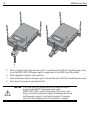
1. Attach the two provided mounting ears (using four ear mounting screws) to the two narrow ens of the
AP6522. Align the ears using the built in ear alignment pin on the access point housing. Torque the screws
to 6 lb-in.
1-0
DIO
RA
A
OL
OT
OR
le
M
nso
Co
oE
1/P
GE
DC
12V
2-1
DIO
RA
2. Place the access point against the wall, ensuring the access point’s Motorola Solutions “bat wings” logo
is in the correct orientation.
3. Mark the screw hole locations on a vertical axis using the ear’s mounting holes.
4. At each point, drill a hole in the wall and insert the anchor.
NOTE
When pre-drilling a hole the recommended hole size is 2.8mm (0.11in.).
5. Place the access point on the anchor. Insert screws through the access point’s mounting ears and into the
anchor.
6. If required, install and attach a Kensington security cable (customer supplied) to the unit’s lock port.
7. Attach an Ethernet cable from the access point to a controller with an 802.3af-compatible power source
or use the PWRS-14000-148R power supply to supply power to the AP6522 (once fully cabled).
8. Attach appropriate antennas to the connectors.
14
AP6522 Access Point
9. Attach an Ethernet cable from the access point to a controller with an 802.3af compatible power source.
10. Verify the access point is receiving power by observing that the LEDs are lit or flashing.
CAUTION
!
If not using a 802.3af capable controller to power the AP6522, ensure
only the AP6522’s designated power supply (PWRS-14000-148R) is
used to supply power to the access point. Using an incorrectly rated
power supply could damage the unit and void the product warranty.
Do not actually connect to the power source until the cabling portion
of the installation is complete.
2.6.3 Wall Mount Procedure - Existing Access Point Replacement
An existing external antenna model AP300 (WSAP-5100-100) or external antenna model AP650 (AP-0650-660X0)
access point, installed on a wall (plenum installation), can be placed by an AP6522. Simply remove the existing
legacy model access point from its mounting screws, leave the mounting hardware in place and install the new
external antenna model AP6522 directly on to the existing mounting hardware. The cabling procedure for such a
replacement is as described in the previous section.
Installation Guide
15
2.7 External Antenna Model Suspended Ceiling T-Bar Mount
Ceiling mount requires holding the AP6522 access point up against a T-bar of a suspended ceiling grid and twisting
the case onto the T-bar. If deploying an external antenna model AP6522 on a ceiling T-Bar, access point mounting
kit (Part No. KT-135628-01) or ceiling mount hardware (SCT-2) is required.
2.7.1 Suspended Ceiling T-Bar Mount Procedure - Using Mounting Kit
The following installation uses the access point mounting kit (Part No. KT-135628-01) to deploy the access point
on a ceiling T-Bar.
1. If required, install and attach a Kensington security cable (customer provided) to the unit’s lock port.
2. Using only the mounting bracket from the mounting kit, rotate and click the mounting bracket into the
mounting slots on the AP6522.
3. Attach an Ethernet cable from the access point to a controller with an 802.3af compatible power source
or use the PWRS-14000-148R power supply to supply power to the AP6522 (once fully cabled).
4. With the ceiling tile raised, slip the T-Bar bracket on to the exposed T-Bar flange.
5. Lower the ceiling tile and verify the stability of the T-Bar mounting bracket connection. There will be no
stability in this assembly until the ceiling tile is lowered on to the T-Bar to secure the mounting hardware.
6. Verify the unit has power by observing the LEDs.
CAUTION
!
If not using an 802.3af capable controller to power the AP6522,
ensure only the AP6522’s designated power supply
(PWRS-14000-148R) is used to supply power to the access point.
Using an incorrectly rated power supply could damage the unit and
void the product warranty. Do not actually connect to the power
source until the cabling portion of the installation is complete.
2.7.2 Suspended Ceiling T-Bar Mount Procedure - Using Ceiling Mount Hardware
The following installation uses the access point ceiling mounting kit (Part No. SCT-2) to deploy the access point on
a ceiling T-Bar.
1.
2.
3.
4.
If required, install and attach a Kensington security cable (customer provided) to the unit’s lock port.
Remove nut from the SCT-2 kit and place assembly and screw through access point mounting ear.
Place the clips from the SCT-2 ceiling mount kit over ceiling T-Bar.
Tighten clips using provided nuts.
16
AP6522 Access Point
1-0
1-0
DIO
DIO
RA
RA
A
OL
OT
OR
M
A
OL
TO
R
MO
le
nso
Co
DC
D
-1
IO2
RA
le
nso
Co
oE
oE
1/P
GE
1/P
GE
12V
DC
12V
-1
IO2
D
RA
5. Attach an Ethernet cable from the access point to a controller with an 802.3af compatible power source
or use the PWRS-14000-148R power supply to supply power to the AP6522 (once fully cabled).
6. Attach appropriate antennas to the connectors.
7. Attach an Ethernet cable from the access point to the controller with an 802.3af compatible power source.
8. Verify the unit has power by observing the LEDs.
CAUTION
!
If not using an 802.3af capable controller to power the AP6522,
ensure only the AP6522’s designated power supply
(PWRS-14000-148R) is used to supply power to the access point.
Using an incorrectly rated power supply could damage the unit and
void the product warranty. Do not actually connect to the power
source until the cabling portion of the installation is complete.
Installation Guide
17
2.8 External Antenna Suspended Ceiling Tile (Plenum) Mount
Ceiling mount requires placing the AP6522 access point above suspended ceiling tile.
NOTE
Notes or warnings about suspended ceiling mounts apply to all
installations where the unit is placed on suspended ceiling tile.
CAUTION
!
Motorola Solutions does not recommend mounting the AP6522 access
point directly to any suspended ceiling tile with a thickness less than
12.7mm (0.5in.) or a suspended ceiling tile with an unsupported span
greater than 660mm (26in.). Motorola Solutions strongly recommends
fitting the AP6522 access point with the supplied mounting ears and
hanging the access point on a pipe or beam.
2.8.1 Suspended Ceiling Mount Hardware
•
•
•
Security cable (optional)
Mounting ears
Customer supplied pipe or channel clamps
2.8.2 Ceiling Mount Procedure
1. If possible, remove the ceiling tile from its frame and place it, finish side down, on a work surface.
2. If required, install and attach a Kensington security cable (customer provided) to the unit’s lock port.
3. Place the access point on the ceiling tile or attach to a plenum beam or pipe using industry available
clamps.
4. Attach appropriate antennas to the connectors.
5. Bring the tile into the ceiling space
6. Attach an Ethernet cable from the access point to a controller with an 802.3af compatible power source
or use the PWRS-14000-148R power supply to supply power to the AP6522 (once fully cabled).
7. Verify the access point is receiving power by observing the LEDs.
8. Place the ceiling tile back in its frame.
CAUTION
!
If not using an 802.3af capable controller to power the AP6522,
ensure only the AP6522’s designated power supply
(PWRS-14000-148R) is used to supply power to the access point.
Using an incorrectly rated power supply could damage the unit and
void the product warranty. Do not actually connect to the power
source until the cabling portion of the installation is complete.
18
AP6522 Access Point
2.9 AP6522 External Antenna Model Antenna Options
Motorola Solutions supports two antenna suites for AP6522 External Antenna models. One antenna suite
supporting the 2.4 GHz band and another antenna suite supporting the 5 GHz band. Select an antenna model best
suited to the intended operational environment of your access point.
Installation Guide
19
The 2.4 GHz antenna suite includes the following models:
Part Number
Antenna Type
ML-2452-APA2-01
Dipole Antenna
ML-2499-SD3-01R
Patch Antenna
ML-2499-HPA3-01R
Omni Antenna
ML-2452-PNA5-01R
Panel Antenna
ML-2452-PTA3M3-036
Omni Antenna
ML-2452-APAG2A1-01 (Black)
ML-2452-APAG2A1-02 (White)
Dipole Antenna
The 5 GHz antenna suite includes the following models:
Part Number
Antenna Type
ML-2452-APA2-01
Dipole Antenna
ML-5299-PTA1-01R
Patch Antenna
ML-5299-HPA1-01R
Omni Antenna
ML-2452-PNA5-01R
Panel Antenna
ML-2452-PTA3M3-036
Omni Antenna
ML-2452-APAG2A1-01 (Black)
ML-2452-APAG2A1-02 (White)
Dipole Antenna
For up-to-date information on supported antennas and antenna specifications, please refer to the Motorola
Solutions Enterprise Wireless LAN Antenna Specification Guide available on the Motorola Solutions Web site. For
more information, refer to http://supportcentral.motorola.com/support/product/manuals.do.
20
AP6522 Access Point
2.10 LED Indicators
Both Integrated Antenna and External Antenna models have LED activity indicators on the front of the case. With
the External Antenna models mounted above a ceiling, LEDs are at the center of an oval badge on the ceiling.
The LEDs provide a status display indicating error conditions, transmission, and network activity for the 5 GHz
802.11an (amber) radio or the 2.4 GHz 802.11bgn (green) radio.
Installation Guide
21
Task
5 GHz Activity LED (Amber)
2.4 GHz Activity LED (Green)
Unadopted
Off
Blink interval at 5 times a second
Normal
Operation
• If this radio band is enabled:
Blink at 5 second interval
• If this radio band is disabled:
Off
• If there is activity on this band:
Blink interval at 1 time per second
• If this radio band is enabled:
Blink at 5 second interval
• If this radio band is disabled:
Off
• If there is activity on this band:
Blink interval at 1 time per second
Firmware
Update
On
Off
Sensor Mode Blink interval at 5 times a second
Blink interval at 5 times a second
22
3
AP6522 Access Point
Initial Access Point Configuration
Once the access point is installed and powered on, complete the following steps to get the device up and running
using the Initial Setup Wizard:
NOTE
When connecting to an AP6522 model access point, note that the baud
rate is 115,200 as opposed to 19,200.
1. Attach an Ethernet cable from the access point to a controller with an 802.3af compatible power source
or use the PWRS-14000-148R power supply to supply power to the AP6522 (once fully cabled).
If your host system is a DHCP server, an IP address is automatically assigned to the AP6522 and can be
used for device connection. However, if a DHCP server is not available, you’ll need to derive the IP address
from the AP6522 MAC address. Using this method, the last two bytes of the AP6522 MAC address become
the last two octets of the IP address.
AP6522 MAC address - 00:C0:23:00:F0:0A
AP6522 IP address equivalent - 169.254.240.10
To derive the AP6522’s IP address using its factory assigned MAC address:
a. Open the Windows calculator be selecting Start > All Programs > Accessories > Calculator. This menu
path may vary slightly depending on your version of Windows.
b. With the Calculator displayed, select View > Scientific. Select the Hex radio button.
c. Enter a hex byte of the AP6522’s MAC address. For example, F0.
d. Select the Dec radio button. The calculator converts F0 into 240. Repeat this process for the last
AP6522 MAC address octet.
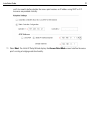
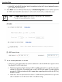
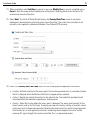
2. Point the Web browser to the AP6522’s IP address (using https://). The following login screen displays.
3. Enter the default username admin in the Username field.
4. Enter the default password motorola in the Password field.
Installation Guide
23
5. Click the Login button to load the management interface.
NOTE
When logging in for the first time, you’re prompted to change the
password to enhance device security in subsequent logins.
NOTE
If you get disconnected when running the wizard, you can connect again
with the access point’s actual IP address (once obtained) and resume the
wizard.
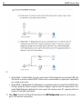
6. Select the Start Wizard button to run the initial setup wizard.
The setup wizard displays the first time the AP6522 user interface is accessed in order to define the
AP6522’s initial configuration.
7. If this is the first time the management interface has been accessed, a dialogue displays to start the
wizard. Select Start Wizard to run the wizard.
24
AP6522 Access Point
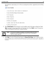
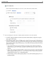
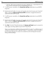
The first page of the Initial AP Setup Wizard displays the Navigation Panel and Introduction for the
configuration activities comprising the access point's initial setup
A green checkmark to the left of an item in the Navigation Panel defines the listed task as having its
minimum required configuration parameters set correctly. A red X defines the task as still requiring at
least one parameter be defined correctly.
Installation Guide
25
The Introduction screen displays a list of the basic configuration activities supported by the Initial Setup
Wizard.
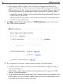
8. Select Save/Commit within each page to save the updates made to that page's configuration. Select
Next to proceed to the next page listed in the Navigation Panel. Select Back to revert to the previous
screen in the Navigation Panel without saving your updates.
NOTE
While you can navigate to any page in the navigation panel, you cannot
complete the Initial AP Setup Wizard until each task in the Navigation
Panel has a green checkmark.
9. Select Next. The Initial AP Setup Wizard displays the Access Point Type screen to define the access
point's Standalone versus Virtual Controller AP functionality and the way the access point is adopted to a
controller.
26
AP6522 Access Point
10. Select an Access Point Type from the following options:
• Virtual Controller AP - When more than one access point is deployed, a single access point can
function as a Virtual Controller AP. Up to 24 access points can be connected to, and managed by, a
single Virtual Controller AP of the same AP6522 model.
• Standalone AP -Select this option to deploy this access point as an autonomous fat access point. A
Standalone AP isn't managed by a Virtual Controller AP, or adopted by a controller.
NOTE If designating the access point as a Standalone AP, Motorola Solutions recommends
the access point’s UI be used exclusively to define its device configuration, and not
the CLI. The CLI provides the ability to define more than one profile and the UI does
not. Consequently, the two interfaces cannot be used collectively to manage profiles
without an administrator encountering problems.
• Adopted to Controller - Select this option when deploying the access point as a controller managed
(Dependent mode) access point. Selecting this option closes the Initial AP Setup Wizard. An adopted
access point obtains its configuration from a profile stored on its managing controller. Any manual
configuration changes are overwritten by the controller upon reboot.
Select the Automatic controller discovery option to enable the access point to be discovered and
adopted using layer 2 settings. If preferring layer 3 adoption, select the Static Controller
Configuration option, and define the addresses of the preferred controllers. If using the static method,
Installation Guide
27
you’ll also need to define whether the access point receives an IP address using DHCP or if IP
resources are provided statically.
11. Select Next. The Initial AP Setup Wizard displays the Access Point Mode screen to define the access
point's routing or bridging mode functionality.
28
AP6522 Access Point
12. Select an Access Point Mode from the available options.
• Router Mode - In Router Mode, the access point routes traffic between the local network (LAN) and
the Internet or external network (WAN). Router mode is recommended in a deployment supported by
just a single access point.
• Bridge Mode - In Bridge Mode, the AP depends on an external router for routing LAN and WAN traffic.
Routing is generally used on one device, whereas bridging is typically used in a larger network. Thus,
select Bridge Mode when deploying this access point with numerous peer APs supporting clients on
both the 2.4 and 5GHz radio bands.
13. Select Next. The Initial AP Setup Wizard displays the LAN Configuration screen to set the access
point's LAN interface configuration.
Installation Guide
29
14. Set the following DHCP and Static IP Address/Subnet information for the LAN interface:
• Use DHCP - Select the checkbox to enable an automatic network address configuration using the
access point’s DHCP server.
• Static IP Address/Subnet - Enter an IP Address and a subnet for the access point's LAN interface. If
Use DHCP is selected, this field is not available. When selecting this option, define the following DHCP
Server and Domain Name Server (DNS) resources, as those fields will become enabled on the bottom
portion of the screen.
• Use on-board DHCP server to assign IP addresses to wireless clients -Select the checkbox to
enable the access point’s DHCP server to provide IP and DNS information to clients on the LAN
interface.
• Range - Enter a starting and ending IP Address range for client assignments on the LAN interface.
Avoid assigning IP addresses from x.x.x.1 - x.x.x.10 and x.x.x.255, as they are often reserved for
standard network services. This is a required parameter.
• Default Gateway - Define a default gateway address for use with the default gateway. This is a
required parameter.
30
AP6522 Access Point
• DNS Forwarding - Select this option to allow a DNS server to translate domain names into IP
addresses. If this option is not selected, a primary and secondary DNS resource must be specified.
DNS forwarding is useful when a request for a domain name is made but the DNS server, responsible
for converting the name into its corresponding IP address, cannot locate the matching IP address.
• Primary DNS - Enter an IP Address for the main Domain Name Server providing DNS services for
the access point's LAN interface.
• Secondary DNS - Enter an IP Address for the backup Domain Name Server providing DNS services
for the access point's LAN interface
15. Select Next. The Initial AP Setup Wizard displays the WAN Configuration screen to set the access
point's WAN interface configuration.
16. Set the following DHCP and Static IP Address/Subnet information for the WAN interface:
• Use DHCP - Select the checkbox to enable an automatic network address configuration using the
access point’s DHCP server.
• Static IP Address/Subnet - Enter an IP Address/Subnet and gateway for the access point's WAN
interface. These are required fields
• The port connected to the WAN - Select the port used as the physical access point connection to the
external network. This ports available differ depending on the access point model deployed. Access
point models with a single port have this option fixed.
Installation Guide
31
• Enable NAT on the WAN Interface - Select the checkbox to allow traffic to pass between the access
point's WAN and LAN interfaces.
17. Select Next. The Initial AP Setup Wizard displays the Radio Configuration screen to define support for
the 2.4GHz radio band, 5GHz radio band or to set the radio's functionality as a dedicated sensor.
NOTE
The ADSP Sensor Server field displays at the bottom of the screen only
if a radio has been dedicated as a sensor.
18. Set the following parameters for the radio:
• Configure as a Data Radio - Select this option to dedicate this radio for WLAN client support in either
the selected 2.4 or 5GHz radio band.
• Radio Frequency Band - Select either the 2.4GHz or 5.0GHz radio band to use with the radio when
selected as a Data Radio. The selected band is used for WLAN client support. Considers selecting
one radio for 2.4GHz and another for 5GHz support when supporting clients in both the 802.11bg
and 802.11n bands.
• Power Level - Use the spinner control to select a 1 - 23 dBm minimum power level to assign to this
radio in selected 2.4 or 5.0 GHz band. 1 dBm is the default setting.
32
AP6522 Access Point
•
Channel Mode - Select either Random, Best or Static. Select Random for use with a 802.11an
radio. To comply with Dynamic Frequency Selection (DFS) requirements in the European Union, the
802.11an radio uses a randomly selected channel each time the access point is powered on.
Select Best to enable the access point to scan non-overlapping channels and listen for beacons
from other access points. After the channels are scanned, it will select the channel with the fewest
access points. In the case of multiple access points on the same channel, it will select the channel
with the lowest average power level. When Constantly Monitor is selected, the access point will
continuously scan the network for excessive noise and sources of interference. Select Static to
assign the access point a permanent channel and scan for noise and interference only when
initialized.
• Configure as a Sensor Radio - Select this option to dedicate the radio to sensor support exclusively.
When functioning as a sensor, the radio scans in sensor mode across all channels within the 2.4 and
5.0GHz bands to identify potential threats within the access point managed network. If dedicating a
radio as a sensor resource, a primary and secondary ADSP server must be specified as an ADSP
management resource.
• Disable the Radio - Select this option to disable this radio, thus prohibiting it from either providing
WLAN or sensor support. Verify this course action with your network administrator before rendering
the radio offline.
19. Select Next. The Initial AP Setup Wizard displays the Wireless LAN Setting screen to define network
address and security settings for two WLAN configurations available to the access point as part of the
Initial Setup Wizard. Once the access point has an initial configuration defined, numerous additional
WLAN configurations can be set.
Installation Guide
33
20. Set the following parameters for each of the two WLAN configurations available as part of this Initial AP
Setup Wizard:
• SSID - Enter or modify the Services Set Identification (SSID) associated with the WLAN. The WLAN
name is auto-generated using the SSID until changed by the user. The maximum number of characters
is 32. Do not use < > | “ & \ ? , This is a required parameter for each WLAN.
• WLAN Type - Set the data protection scheme used by clients and access points within the WLAN. The
following options are available:
• No Authentication and no Encryption - Select this option to provide no security between the access
point and connected clients on this WLAN.
• Captive Portal Authentication and No Encryption - Select this option to use a Web page (either
internally or externally hosted) to authenticate users before access is granted to the network. If
using this option, define whether a local or external RADIUS authentication resource is used.
• PSK Authentication and WPA2 Encryption - Select the option to implement a pre-shared key that
must be correctly shared between the access point and requesting clients using this WLAN. If using
this option, specify a WPA key in either ASCII (8-63 characters) or HEX (64 characters) format.
• EAP Authentication and WPA2 Encryption - Select this option to authenticate clients within this
WLAN through the exchange and verification of certificates. If using this option, define whether a
local or external RADIUS authentication resource is used.
• WPA Key - If a WPA key is required (PSK Authentication and WPA2 Encryption), enter an alphanumeric
string of 8 to 63 ASCII characters or 64 HEX characters as the primary string both transmitting and
receiving authenticators must share. The alphanumeric string allows character spaces. This
passphrase saves the administrator from entering the 256-bit key each time keys are generated.
• RADIUS Server - If the WLAN requires a RADIUS server to validate user credentials, designate
whether the access point is using an External RADIUS Server resource or the access point's own
Onboard RADIUS Server. If using an external RADIUS server resource, provide the IP address of the
external server and the shared secret used to authenticate the request.
NOTE
If using the access point’s onboard RADIUS server, an additional RADIUS
Server Configuration screen displays within the Navigation Panel on
the left-hand side of the screen. Use this screen to create user accounts
validated when the access point authenticates client connection requests
to the onboard RADIUS server.
21. Select Next. The Initial AP Setup Wizard displays the RADIUS Server Configuration screen if the
access point’s onboard RADIUS server is required to validate user requests. If an onboard RADIUS server
is not required, the Initial AP Setup Wizard displays the Country/Date/Time screen to set device
deployment, administrative contact and system time information.
34
AP6522 Access Point
22. Refer to the Username, Password, Description and Actions columns to review credentials of existing
RADIUS Server user accounts. Add new accounts or edit the properties of existing accounts as updates
are required.
23. Refer to the Add On-Board RADIUS Server Users field to set the following parameters for a user
account:
• Username - If adding a new user account, create a username up to X characters in length. The
username cannot be revised if modifying the user configuration. This is a required parameter.
• Password - Provide (or modify) a password between X - X characters in length entered each time a
requesting client attempts access to the AP managed network using the access point's onboard
RADIUS server. This is a required parameter.
• Confirm Password - Re-enter (or modify) the password as a means of confirming the password. This is
a required parameter.
• Description - Optionally provide a description of the user account as means of further differentiating
it from others.
Installation Guide
35
24. When completed, select Add User to commit a new user, Modify User to commit a modified user or
Reset to clear the screen without updating the configuration. Selecting Reset clears the field of all
entered user account information.
25. Select Next. The Initial AP Setup Wizard displays the Country/Date/Time screen to set device
deployment, administrative contact and system time information. The system time can either be set
manually or be supplied by a dedicated Network Time Protocol (NTP) resource.
26. Refer to the Country and Time Zone field to set the following device deployment information:
• Location - Define the location of the access point. The Location parameter acts as a reminder of where
the AP is deployed within the Motorola Solutions managed wireless network.
• Contact - Specify the contact information for the administrator. The credentials provided should
accurately reflect the individual responding to service queries.
• Country - Select the Country where the access point is deployed. The access point prompts for the
correct country code on the first login. A warning message also displays stating an incorrect country
setting may result in illegal radio operation. Selecting the correct country is central to legal operation.
Each country has its own regulatory restrictions concerning electromagnetic emissions and the
maximum RF signal strength that can be transmitted. This is a required parameter.
36
AP6522 Access Point
• Time Zone - Set the time zone where the access point is deployed. This is a required parameter. The
setting should be complimentary with the selected deployment country.
27. If an NTP resource is unavailable, set the System Date and Time (calendar date, time and AM/PM
designation).
28. Optionally enter the IP address of a server used to provide system time to the access point. Once the IP
address is entered, the Network Time Protocol (NTP) functionality is engaged automatically for
synchronization with the NTP resource.
29. If an NTP resource is unavailable, set the System Date and Time (calendar date, time and AM/PM
designation).
30. Optionally enter the IP address of a server used to provide system time to the access point. Once the IP
address is entered, the Network Time Protocol (NTP) functionality is engaged automatically for
synchronization with the NTP resource.
31. Select Next. The Initial AP Setup Wizard displays the Summary and Commit screen to summarize the
screens (pages) and settings updated using the Initial AP Setup Wizard.
There's no user intervention or additional settings required within this screen. It’s an additional means of
validating the configuration before its deployed. However, if a screen displays settings not intended as
part of the initial configuration, the screen can be selected from within the Navigation Panel and its
settings modified accordingly.
Installation Guide
37
If the configuration displays as intended, select the Save/Commit button to implement these settings to
the access point’s configuration. If additional changes are warranted based on the summary, either select
the target page from the Navigational Panel, or use the Back and Next buttons to scroll to the target
screen
For information on how use a Motorola Solutions RFS Series controller to manage an AP6522 access
point, refer to http://supportcentral.motorola.com/support/product/manuals.do.
38
4
AP6522 Access Point
Specifications
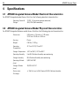
4.1 AP6522 Integrated Antenna Model Electrical Characteristics
An AP6522 Integrated model Access Point has the following electrical characteristics:
Operating Current &
Voltage
12VDC, 1A (accessory power connector)
48V,0.25A (PoE connector)
4.2 AP6522 Integrated Antenna Model Physical Characteristics
An AP6522 Integrated Antenna model Access Point has the following physical characteristics:
Dimensions
9.38 inches x 7.5 inches x 1.38 inches
23.82 cm x 19.50 cm x 3.50 cm
Housing
Plastic
Weight
0.90 lbs / 0.40 kg
Operating
Temperature
32°F to 104°F/0°C to 40°C
Storage Temperature -40°F to 185°F/-40°C to 85°C
Operating Humidity
5 to 95% Relative Humidity non-condensing
Storage Humidity
85% Relative Humidity non-condensing
Operating Altitude
(max)
8,000 ft @ 28C
Storage Altitude
(max)
30,000 ft @ 12C
Electrostatic
Discharge
+/-15kV Air and +/-8kV Contact @ 50% Relative Humidity
Installation Guide
39
4.3 AP6522 External Antenna Model Electrical Characteristics
An AP6522 External Antenna model Access Point has the following electrical characteristics:
Operating Current &
Voltage
12VDC, 1A (accessory power connector)
48V,0.25A (PoE connector)
4.4 AP6522 External Antenna Model Physical Characteristics
An AP6522 External Antenna model Access Point has the following physical characteristics:
Dimensions
7.88 inches x 5.00 inches x 1.00 inches
20.01 cm x 12.70 cm x 2.54 cm
Housing
Metal
Weight
1.45 lbs / 0.65 kg
Operating
Temperature
32°F to 104°F/0°C to 40°C
Storage Temperature -40°F to 185°F/-40°C to 85°C
Operating Humidity
5 to 95% Relative Humidity non-condensing
Storage Humidity
85% Relative Humidity non-condensing
Operating Altitude
(max)
8,000 ft @ 28C
Storage Altitude
(max)
30,000 ft @ 12C
Electrostatic
Discharge
+/-15kV Air and +/-8kV Contact @ 50% Relative Humidity
40
AP6522 Access Point
4.5 Radio Characteristics
The AP6522 model Access Points have the following radio characteristics:
Operating Channels
All channels from 4920 MHz to 5825 MHz except channel
52 -64
Channels 1-13 (2412-2472 MHz)
Channel 14 (2484 MHz) Japan only
Actual operating frequencies depend on regulatory approval for the
country of use.
Data Rates Supported 802.11b: 1,2,5.5,11Mbps
802.11g: 1,2,5.5,11,6,9,12,18,24,36,48, and 54Mbps
802.11a: 6,9,12,18,24,36,48, and 54Mbps
802.11n: MCS 0-15 up to 300Mbps
Wireless Medium
Direct Sequence Spread Spectrum (DSSS),
Orthogonal Frequency Division Multiplexing (OFDM)
Spatial multiplexing (MIMO)
Network Standards
802.11a, 802.11b, 802.11g, 802.3, 802.11n (Draft 2.0)
Maximum Available
Transmit Power
Maximum available conducted transmit power per chain:
2.4 GHz: 21dBm
Maximum available conducted transmit power all chains:
2.4 GHz: 24dBm
Maximum available conducted transmit power per chain:
5 GHz: 19dBm
Maximum available conducted transmit power all chains:
5 GHz: 22dBm
Transmit Power
Adjustment
1dB increments
Installation Guide
5
41
Regulatory Information
This device is approved under the Symbol Technologies, Inc. brand: Symbol Technologies, Inc. is a wholly owned subsidiary of Motorola
Solutions, Inc. (collectively "Motorola").
This guide applies to Model Number AP6522. The AP6522 access point is approved under MODEL: AP-0622.
All Motorola/Symbol devices are designed to be compliant with rules and regulations in locations they are sold and will be labeled as
required.
Local language translations are available at the following website:
http://supportcentral.motorola.com/
Any changes or modifications to Motorola/Symbol Technologies equipment, not expressly approved by Motorola/Symbol Technologies, could
void the user’s authority to operate the equipment.
Motorola/Symbol devices are professionally installed, the Radio Frequency Output Power will not exceed the maximum allowable limit for
the country of operation.
Antennas: Use only the supplied or an approved replacement antenna. Unauthorized antennas, modifications, or attachments could cause
damage and may violate regulations.
This device is only to be used with a Motorola/Symbol Technologies Wireless Switch.
Country Approvals
Regulatory markings, subject to certification, are applied to the device signifying the radio(s) is/are approved for use in the following
countries: United States, Canada, Japan, China, S. Korea, Australia, and Europe.
Please refer to the Declaration of Conformity (DoC) for details of other country markings. This is available at: http://www.motorola.com/doc
Note: For 2.4GHz or 5GHz Products: Europe includes, Austria, Belgium, Bulgaria, Czech Republic, Cyprus, Denmark, Estonia, FinlFor 2.4GHz
or 5GHz Products: Europe includes, Austria, Belgium, Bulgaria, Czech Republic, Cyprus, Denmark, Estonia, Finland, France, Germany, Greece,
Hungary, Iceland, Ireland, Italy, Latvia, Liechtenstein, Lithuania, Luxembourg, Malta, Netherlands, Norway, Poland, Portugal, Romania,
Slovak Republic, Slovenia, Spain, Sweden, Switzerland and the United Kingdom.
Operation of the device without regulatory approval is illegal.
Health and Safety Recommendations
Country Selection
Select only the country in which you are using the device. Any other selection will make the operation of this device illegal.
Frequency of Operation – FCC and IC
You are reminded of the need to observe restrictions on the use of radio devices in fuel depots, chemical plants etc. and areas where the air
contains chemicals or particles (such as grain, dust, or metal powders).
5 GHz Only
The use in the UNII (Unlicensed National Information Infrastructure) band 1 (5150-5250 MHz) is restricted to Indoor Use Only; any other use
will make the operation of this device illegal.
42
AP6522 Access Point
Industry Canada Statement:
Caution: The device for the band 5150-5250 MHz is only for indoor usage to reduce potential for harmful interference to co-Channel mobile
satellite systems. High power radars are allocated as primary users (meaning they have priority) of 5250-5350 MHz and 5650-5850 MHz and
these radars could cause interference and/or damage to LE-LAN devices.
Avertissement: Le dispositif fonctionnant dans la bande 5150-5250 MHz est réservé uniquement pour une utilisation à l'intérieur afin de
réduire les risques de brouillage préjudiciable aux systèmes de satellites mobiles utilisant les mêmes canaux.
Les utilisateurs de radars de haute puissance sont désignés utilisateurs principaux (c.-à-d., qu'ils ont la priorité) pour les bands 5250-5350
MHz et 5650-5850 MHz et que ces radars pourraient causer du brouillage et/ou des dommages aux dispositifs LAN-EL.
Health and Safety Recommendations
Warnings for Use of Wireless Devices
Please observe all warning notices with regard to the usage of wireless devices.
Potetially Hazerdous Atmospheres - Fixed Installations
You are reminded of the need to observe restrictions on the use of radio devices in fuel depots, chemical plants etc. and areas where the air
contains chemicals or particles (such as grain, dust, or metal powders).
Safety in Hospitals
Wireless devices transmit radio frequency energy and may affect medical electrical equipment. When installed adjacent to other
equipment, it is advised to verify that the adjacent equipment is not adversely affected.
Pacemakers
Pacemaker manufacturers recommended that a minimum of 15cm (6 inches) be maintained between a handheld wireless device and a
pacemaker to avoid potential interference with the pacemaker. These recommendations are consistent with independent research and
recommendations by Wireless Technology Research.
Persons with Pacemakers:
• Should ALWAYS keep the device more than 15cm (6 inches) from their pacemaker when turned ON.
• Should not carry the device in a breast pocket.
• Should use the ear furthest from the pacemaker to minimize the potential for interference.
• If you have any reason to suspect that interference is taking place, turn OFF your device.
Other Medical Devices
Please consult your physician or the manufacturer of the medical device, to determine if the operation of your wireless product may interfere
with the medical device.
RF Exposure Guidelines
Safety Information
Reducing RF Exposure - Use Properly
Only operate the device in accordance with the instructions supplied.
Installation Guide
43
International
The device complies with internationally recognized standards covering human exposure to electromagnetic fields from radio devices. For
information on “International” human exposure to electromagnetic fields refer to the Motorola/Symbol Declaration of Conformity (DoC) at:
http://www.motorola.com/doc
EU
Remote and Standalone Antenna Configurations
To comply with EU RF exposure requirements, antennas that are mounted externally at remote locations or operating near users at
stand-alone desktop of similar configurations must operate with a minimum separation distance of 20 cm from all persons.
US and Canada
Co-located statement
To comply with FCC RF exposure compliance requirement, the antennas used for this transmitter must not be co-located or operating in
conjunction with any other transmitter/antenna except those already approved in this filling.
Remote and Standalone Antenna Configurations
To comply with FCC RF exposure requirements, antennas that are mounted externally at remote locations or operating near users at
stand-alone desktop of similar configurations must operate with a minimum separation distance of 20 cm from all persons.
Power Supply
Use ONLY a LISTED Motorola, Type no. PWRS-14000-148R (12VDC @ 4.16A), direct plug-in power supply, marked Class 2 (IEC60950-1, SELV).
This device can be powered from a 802.3af compliant power source which is certified by the appropriate agencies.
Use of alternative Power Supply will invalidate any approvals given to this unit and may be dangerous.
Wireless Devices - Countries
Country Selection
Select only the country in which you are using the device. Any other selection will make the operation of this device illegal.
NOTE
The US only models (AP-6522-66030-US and AP-6522-66040-US) have the country code
permanently set to the US. The EU only models (AP-6522-66030-EU and
AP-6522-66040-EU) have the country code permanently set to Europe. The WR models
(AP-6522-66030-WR and AP-6522-66040-WR) cannot be configured for use in the US or
Europe.
Operation in the US and Canada
The use on UNII (Unlicensed National Information Infrastructure) Band 1 5150-5250 MHz is restricted to indoor use only, any other use will
make the operation of this device illegal.
The available channels for 802.11 bg operation in the US are Channels 1 to 11. The range of channels is limited by firmware.
44
AP6522 Access Point
Radio Frequency Interference Requirements—FCC
This equipment has been tested and found to comply with the limits for a Class B digital device, pursuant to Part 15 of
the FCC rules. These limits are designed to provide reasonable protection against harmful interference in a residential
installation. This equipment generates, uses and can radiate radio frequency energy and, if not installed and used in
accordance with the instructions, may cause harmful interference to radio communications. However there is no
guarantee that interference will not occur in a particular installation. If this equipment does cause harmful interference to radio or television
reception, which can be determined by turning the equipment off and on, the user is encouraged to try to correct the interference by one or
more of the following measures:
•
•
•
•
Reorient or relocate the receiving antenna
Increase the separation between the equipment and receiver
Connect the equipment into an outlet on a circuit different from that to which the receiver is connected
Consult the dealer or an experienced radio/TV technician for help.
Radio Transmitters (Part 15)
This device complies with Part 15 of the FCC Rules. Operation is subject to the following two conditions: (1) this device may not cause harmful
interference, and (2) this device must accept any interference received, including interference that may cause undesired operation.
Radio Frequency Interference Requirements – Canada
This Class B digital apparatus complies with Canadian ICES-003.
Cet appareil numérique de la classe B est conforme à la norme NMB-003 du Canada.
Radio Transmitters
For RLAN Devices:
The use of 5 GHz RLAN’s, for use in Canada, have the following restrictions:
•
Restricted Band 5.60 – 5.65 GHz
This device complies with RSS 210 of Industry Canada. Operation is subject to the following two conditions: (1) this device may not cause
harmful interference and (2) this device must accept any interference received, including interference that may cause undesired operation.
Ce dispositif est conforme à la norme CNR-210 d'Industrie Canada applicable aux appareils radio exempts de licence. Son fonctionnement
est sujet aux deux conditions suivantes: (1) le dispositif ne doit pas produire de brouillage préjudiciable, et (2) ce dispositif doit accepter
tout brouillage reçu, y compris un brouillage susceptible de provoquer un fonctionnement indésirable.
Label Marking: The Term "IC:" before the radio certification signifies that Industry Canada technical specifications were met.
Installation Guide
45
CE Marking and European Economic Area (EEA)
The use of 2.4GHz RLAN’s, for use through the EEA, have the following restrictions:
•
•
•
Maximum radiated transmit power of 100 mW EIRP in the frequency range 2.400 -2.4835 GHz.
France outside usage, the equipment is restricted to 2.400-2.45 GHz frequency range.
Italy requires a user license for outside usage.
Statement of Compliance
Motorola hereby, declares that this device is in compliance with the essential requirements and other relevant provisions of Directive
1999/5/EC. A Declaration of Conformity may be obtained from http://www.motorola.com/doc.
Korea Warning Statement for Class B
Other Countries
Australia
Use of 5GHz RLAN’s in Australia is restricted in the following band 5.50 – 5.65GHz.
Brazil
Declarações Regulamentares para AP6522 - Brasil
Nota: A marca de certificação se aplica ao Transceptor, modelo AP6522. Este equipamento opera em caráter secundário, isto é, não tem
direito a proteção contra interferência prejudicial, mesmo de estações do mesmo tipo, e não pode causar interferência a sistemas operando
em caráter primário. Para maiores informações sobre ANATEL consulte o site: www.anatel.gov.br
Chile
Este equipo cumple con la Resolución No 403 de 2008, de la Subsecretaria de telecomunicaciones, relativa a radiaciones electromagnéticas.
Mexico
Restrict Frequency Range to: 2.450 – 2.4835 GHz.
46
Taiwan
5.25-5.35 ⿁䌿丏ᐊܻ᪡П⛵㎮䊛㿞ڇ䔌䀁ˈ٭䰤ᮐᅸܻՓ⫼
Korea
Turkish WEEE Statement of Compliance
EEE Yönetmeliğine Uygundur
AP6522 Access Point
Installation Guide
Waste Electrical and Electronic Equipment (WEEE)
English: For EU Customers: All products at the end of their life must be
returned to Motorola for recycling. For information on how to return product,
please go to: http://www.motorola.com/recycling/weee.
Français: Clients de l'Union Européenne: Tous les produits en fin de cycle
de vie doivent être retournés à Motorola pour recyclage. Pour de plus amples
informations sur le retour de produits, consultez :
http://www.motorola.com/recycling/weee.
Español: Para clientes en la Unión Europea: todos los productos deberán
entregarse a Motorola al final de su ciclo de vida para que sean reciclados.
Si desea más información sobre cómo devolver un producto, visite:
http://www.motorola.com/recycling/weee.
Bulgarish: За клиенти от ЕС: След края на полезния им живот всички
продукти трябва да се връщат на Motorola за рециклиране. За информация
относно връщането на продукти, моля отидете на адрес:
http://www.motorola.com/recycling/weee.
Deutsch: Für Kunden innerhalb der EU: Alle Produkte müssen am Ende
ihrer Lebensdauer zum Recycling an Motorola zurückgesandt werden.
Informationen zur Rücksendung von Produkten finden Sie unter
http://www.motorola.com/recycling/weee.
Italiano: per i clienti dell'UE: tutti i prodotti che sono giunti al termine del
rispettivo ciclo di vita devono essere restituiti a Motorola al fine di consentirne
il riciclaggio. Per informazioni sulle modalità di restituzione, visitare il
seguente sito Web: http://www.motorola.com/recycling/weee.
Português: Para clientes da UE: todos os produtos no fim de vida devem
ser devolvidos à Motorola para reciclagem. Para obter informações sobre
como devolver o produto, visite: http://www.motorola.com/recycling/weee.
Nederlands: Voor klanten in de EU: alle producten dienen aan het einde van
hun levensduur naar Motorola te worden teruggezonden voor recycling.
Raadpleeg http://www.motorola.com/recycling/weee voor meer informatie
over het terugzenden van producten.
Polski: Klienci z obszaru Unii Europejskiej: Produkty wycofane z eksploatacji
nale¿y zwróciæ do firmy Motorola w celu ich utylizacji. Informacje na temat
zwrotu produktów znajduj¹ siê na stronie internetowej
http://www.motorola.com/recycling/weee.
Čeština: Pro zákazníky z EU: Všechny produkty je nutné po skonèení jejich
životnosti vrátit spoleènosti Motorola k recyklaci. Informace o zpùsobu
vrácení produktu najdete na webové stránce:
http://www.motorola.com/recycling/weee.
Eesti: EL klientidele: kõik tooted tuleb nende eluea lõppedes tagastada
taaskasutamise eesmärgil Motorola'ile. Lisainformatsiooni saamiseks toote
tagastamise kohta külastage palun aadressi:
http://www.motorola.com/recycling/weee.
Magyar: Az EU-ban vásárlóknak: Minden tönkrement terméket a Motorola
vállalathoz kell eljuttatni újrahasznosítás céljából. A termék
visszajuttatásának módjával kapcsolatos tudnivalókért látogasson el a
http://www.motorola.com/recycling/weee weboldalra.
47
48
Svenska: För kunder inom EU: Alla produkter som uppnått sin livslängd
måste returneras till Motorola för återvinning. Information om hur du
returnerar produkten finns på http://www.motorola.com/recycling/weee.
Suomi: Asiakkaat Euroopan unionin alueella: Kaikki tuotteet on palautettava
kierrätettäväksi Motorola-yhtiöön, kun tuotetta ei enää käytetä. Lisätietoja
tuotteen palauttamisesta on osoitteessa
http://www.motorola.com/recycling/weee.
Dansk: Til kunder i EU: Alle produkter skal returneres til Motorola til
recirkulering, når de er udtjent. Læs oplysningerne om returnering af
produkter på: http://www.motorola.com/recycling/weee.
Ελληνικά: Για πελάτες στην Ε.Ε.: Όλα τα προϊόντα, στο τέλος της διάρκειας
ζωής τους, πρέπει να επιστρέφονται στην Motorola για ανακύκλωση. Για
περισσότερες πληροφορίες σχετικά με την επιστροφή ενός προϊόντος,
επισκεφθείτε τη διεύθυνση http://www.motorola.com/recycling/weee στο
Διαδίκτυο.
Malti: Għal klijenti fl-UE: il-prodotti kollha li jkunu waslu fl-aħħar tal-ħajja ta'
l-użu tagħhom, iridu jiġu rritornati għand Motorola għar-riċiklaġġ. Għal aktar
tagħrif dwar kif għandek tirritorna l-prodott, jekk jogħġbok żur:
http://www.motorola.com/recycling/weee.
Românesc: Pentru clienţii din UE: Toate produsele, la sfârşitul duratei lor de
funcţionare, trebuie returnate la Motorola pentru reciclare. Pentru informaţii
despre returnarea produsului, accesaţi:
http://www.motorola.com/recycling/weee.
Slovenski: Za kupce v EU: vsi izdelki se morajo po poteku življenjske dobe
vrniti podjetju Motorola za reciklažo. Za informacije o vračilu izdelka obiščite:
http://www.motorola.com/recycling/weee.
Slovenčina: Pre zákazníkov z krajín EU: Všetky výrobky musia byť po
uplynutí doby ich životnosti vrátené spoločnosti Motorola na recykláciu.
Bližšie informácie o vrátení výrobkov nájdete na:
http://www.motorola.com/recycling/weee.
Lietuvių: ES vartotojams: visi gaminiai, pasibaigus jų eksploatacijos laikui,
turi būti grąžinti utilizuoti į kompaniją „Motorola“. Daugiau informacijos, kaip
grąžinti gaminį, rasite: http://www.motorola.com/recycling/weee.
Latviešu: ES klientiem: visi produkti pēc to kalpošanas mūža beigām ir
jānogādā atpakaļ Motorola otrreizējai pārstrādei. Lai iegūtu informāciju par
produktu nogādāšanu Motorola, lūdzu, skatiet:
http://www.motorola.com/recycling/weee.
Türkçe: AB Müşterileri için: Kullanım süresi dolan tüm ürünler geri
dönüştürme için Motorola'ya iade edilmelidir. Ürünlerin nasıl iade edileceği
hakkında bilgi için lütfen şu adresi ziyaret edin:
http://www.motorola.com/recycling/weee.
AP6522 Access Point
Installation Guide
6
49
Part Numbers, Support and Sales
Part Number
Description
AP-6522-66030-US
Dual 802.11n radio AP6522. Plastic enclosure with internal antennas.
For use in the US deployments only.
AP-6522-66030-EU
Dual 802.11n radio AP6522. Plastic enclosure with internal antennas.
For use in European countries only.
AP-6522-66030-WR
Dual 802.11n radio AP6522. Plastic enclosure with internal antennas.
For use in non-US countries only.
AP-6522-66040-US
Dual 802.11n radio AP6522. Metal enclosure with external antenna
connectors. For use in US deployments only.
AP-6522-66040-EU
Dual 802.11n radio AP6522. Metal enclosure with external antenna
connectors. For use in European countries only .
AP-6522-66040-WR
Dual 802.11n radio AP6522. Metal enclosure with external antenna
connectors. For use in non-US countries only .
Motorola Solutions Support Central
If you have a problem with your equipment, contact support for your region. Support and issue resolution is
provided for products under warranty or that are covered by a services agreement. Contact information and web
self-service is available by visiting http://supportcentral.motorola.com/.
When contacting support, please provide the following information:
• Serial number of the unit
• Model number or product name
• Software type and version number
Motorola Solutions responds to calls by email or telephone within the time limits set forth in support agreements.
If you purchased your product from a Motorola Solutions business partner, contact that business partner for
support.
Customer Support Web Sites
Motorola Solutions‘ Support Central Web site, located at http://supportcentral.motorola.com/ provides
information and online assistance including developer tools, software downloads, product manuals and online
repair requests.
Manuals
http://supportcentral.motorola.com/support/product/manuals.do
50
7
AP6522 Access Point
Motorola Solutions, Inc. End-User License Agreement
BY DOWNLOADING, INSTALLING, OR USING THE SOFTWARE DESCRIBED IN THIS DOCUMENT, YOU OR THE ENTITY OR COMPANY THAT
YOU REPRESENT ("LICENSEE") ARE UNCONDITIONALLY CONSENTING TO BE BOUND BY AND ARE BECOMING A PARTY TO THIS LICENSE
AGREEMENT ("AGREEMENT"). LICENSEE'S USE OR CONTINUED USE OF THE DOWNLOADED OR INSTALLED MATERIALS SHALL ALSO
CONSTITUTE ASSENT TO THE TERMS OF THIS AGREEMENT. IF LICENSEE DOES NOT UNCONDITIONALLY AGREE TO ALL OF THE TERMS
OF THIS AGREEMENT, DO NOT CONTINUE THE INSTALLATION PROCESS. IF THESE TERMS ARE CONSIDERED AN OFFER, ACCEPTANCE IS
EXPRESSLY LIMITED TO AND EXPRESSLY CONTINGENT UPON THESE TERMS. IF YOU ARE ACCEPTING THESE TERMS ON BEHALF OF A
COMPANY, ANOTHER PERSON OR ANY OTHER LEGAL ENTITY, YOU REPRESENT AND WARRANT THAT YOU HAVE THE AUTHORITY TO
BIND THAT COMPANY, PERSON OR ENTITY.
1
LICENSE GRANT. Subject to the terms of this Agreement, Motorola, Inc. and/or its subsidiaries ("Licensor") hereby grants Licensee a
limited, personal, non-sublicensable, non-transferable, nonexclusive license to use the software that Licensee is about to download
or install and the documentation that accompanies it (collectively, the "Software") for Licensee's personal use in connection with
hardware produced by Licensor and only in accordance with the accompanying documentation. Licensee may download, install and
use the Software only on a single computer. Licensee may make one copy of the Software (excluding any documentation) for backup
purposes, provided that copyright and other restricted rights notices of Licensor and its suppliers are reproduced exactly.
2
LICENSE RESTRICTIONS. Except as expressly permitted by this Agreement, Licensee shall not, nor permit anyone else to, directly or
indirectly: (i) copy (except for one backup copy), modify, distribute or create derivative works based upon the Software; (ii) reverse
engineer, disassemble, decompile or otherwise attempt to discover the source code or structure, sequence and organization of the
Software; or (iii) rent, lease, or use the Software for timesharing or service bureau purposes, or otherwise use the Software for any
commercial purpose/on behalf of any third party. Licensee shall maintain and not remove or obscure any proprietary notices on the
Software, and shall reproduce such notices exactly on all permitted copies of the Software. All title, ownership rights, and intellectual
property rights in and to the Software, and any copies or portions thereof, shall remain in Licensor and its suppliers or licensors.
Licensee understands that Licensor may modify or discontinue offering the Software at any time. The Software is protected by the
copyright laws of the United States and international copyright treaties. The Software is licensed, not sold. This Agreement does not
give Licensee any rights not expressly granted herein.
3
INTELLECTUAL PROPERTY; CONTENT. All title and intellectual property rights in and to the Software (including but not limited to any
images, photographs, animations, video, audio, music, text and "applets" incorporated into the Software), and any copies you are
permitted to make herein are owned by Licensor or its suppliers. All title and intellectual property rights in and to the content which
may be accessed through use of the Software is the property of the respective content owner and may be protected by applicable
copyright or other intellectual property laws and treaties. This EULA grants you no rights to use such content. As a condition to
Licensee's use of the Software, Licensee represents, warrants and covenants that Licensee will not use the Software: (i) to infringe
the intellectual property rights or proprietary rights, or rights of publicity or privacy, of any third party; (ii) to violate any applicable law,
statute, ordinance or regulation; (iii) to disseminate information or materials in any form or format ("Content") that are harmful,
threatening, abusive, harassing, tortuous, defamatory, vulgar, obscene, libelous, or otherwise objectionable; or (iv) to disseminate any
software viruses or any other computer code, files or programs that may interrupt, destroy or limit the functionality of any computer
software or hardware or telecommunications equipment. Licensee, not Licensor, remains solely responsible for all Content that
Licensee uploads, posts, e-mails, transmits, or otherwise disseminates using, or in connection with, the Software.
4
FEES; SUPPORT AND UPGRADES. Licensor may, at Licensor's sole option, provide support services related to the Software ("Support
Services"). Nothing in this Agreement grants Licensee any right to receive any Support Services. Use of any Support Services provided
is governed by the Licensor policies and programs described in the user manual, in "online" documentation, and/or in other
Licensor-provided materials or support agreements. Any supplemental software code provided to you as part of any Support Services
shall be considered part of the Software and subject to the terms and conditions of this EULA. With respect to technical information
you provide to Licensor as part of any Support Services, Licensor may use such information for its business purposes, including for
product support and development. Licensor will not utilize such technical information in a form that personally identifies Licensee.
5
TERMINATION. Either party may terminate this Agreement at any time, with or without cause, upon written notice. Any termination of
this Agreement shall also terminate the licenses granted hereunder. Upon termination of this Agreement for any reason, Licensee
Installation Guide
51
shall return all copies of the Software to Licensor, or destroy and remove from all computers, hard drives, networks, and other storage
media all copies of the Software, and shall so certify to Licensor that such actions have occurred. Sections 2-13 shall survive
termination of this Agreement.
6
DISCLAIMER OF WARRANTIES. To the maximum extent permitted by applicable law, Licensor and its suppliers provide the Software
and any (if any) Support Services AS IS AND WITH ALL FAULTS, and hereby disclaim all warranties and conditions, either express,
implied or statutory, including, but not limited to, any (if any) implied warranties or conditions of merchantability, of fitness for a
particular purpose, of lack of viruses, of accuracy or completeness of responses, of results, and of lack of negligence or lack of
workmanlike effort, all with regard to the Software, and the provision of or failure to provide Support Services. ALSO, THERE IS NO
WARRANTY OR CONDITION OF TITLE, QUIET ENJOYMENT, QUIET POSSESSION, CORRESPONDENCE TO DESCRIPTION, OR
NON-INFRINGEMENT WITH REGARD TO THE SOFTWARE. THE ENTIRE RISK AS TO THE QUALITY OF OR ARISING OUT OF USE OR
PERFORMANCE OF THE SOFTWARE AND SUPPORT SERVICES, IF ANY, REMAINS WITH LICENSEE.
7
EXCLUSION OF INCIDENTAL, CONSEQUENTIAL AND CERTAIN OTHER DAMAGES. TO THE MAXIMUM EXTENT PERMITTED BY
APPLICABLE LAW, IN NO EVENT SHALL LICENSOR OR ITS SUPPLIERS BE LIABLE FOR ANY GENERAL, SPECIAL, INCIDENTAL, DIRECT,
INDIRECT, OR CONSEQUENTIAL DAMAGES WHATSOEVER (INCLUDING, BUT NOT LIMITED TO, DAMAGES FOR LOSS OF PROFITS OR
CONFIDENTIAL OR OTHER INFORMATION, FOR BUSINESS INTERRUPTION, FOR PERSONAL INJURY, FOR LOSS OF PRIVACY, FOR
FAILURE TO MEET ANY DUTY INCLUDING OF GOOD FAITH OR OF REASONABLE CARE, FOR NEGLIGENCE, AND FOR ANY OTHER
PECUNIARY OR OTHER LOSS WHATSOEVER) ARISING OUT OF OR IN ANY WAY RELATED TO THE USE OF OR INABILITY TO USE THE
SOFTWARE, THE PROVISION OF OR FAILURE TO PROVIDE SUPPORT SERVICES, OR OTHERWISE UNDER OR IN CONNECTION WITH
ANY PROVISION OF THIS AGREEMENT, EVEN IN THE EVENT OF THE FAULT, TORT (INCLUDING NEGLIGENCE), STRICT LIABILITY,
BREACH OF CONTRACT OR BREACH OF WARRANTY OF LICENSOR OR ANY SUPPLIER, AND EVEN IF LICENSOR OR ANY SUPPLIER
HAS BEEN ADVISED OF THE POSSIBILITY OF SUCH DAMAGES.
8
LIMITATION OF LIABILITY AND REMEDIES. Notwithstanding any damages that Licensee might incur for any reason whatsoever
(including, without limitation, all damages referenced above and all direct or general damages), the entire liability of Licensor and any
of its suppliers under any provision of this Agreement and Licensee's exclusive remedy for all of the foregoing shall be limited to the
greater of the amount actually paid by Licensee for the Software or U.S.$5.00. The foregoing limitations, exclusions and disclaimers
shall apply to the maximum extent permitted by applicable law, even if any remedy fails its essential purpose.
9
INDEMNITY. Licensee agrees that Licensor shall have no liability whatsoever for any use Licensee makes of the Software. Licensee
shall indemnify and hold harmless Licensor from any claims, damages, liabilities, costs and fees (including reasonable attorney fees)
arising from Licensee's use of the Software as well as from Licensee's failure to comply with any term of this Agreement.
10
FAULT TOLERANCE. The Software is not fault-tolerant and is not designed, manufactured or intended for use or resale in on-line
control equipment in hazardous environments requiring fail-safe performance, such as, but not limited to, the operation of nuclear
facilities, aircraft navigation or communication systems, air traffic control, life support machines, or weapons systems, in which the
failure of the Software could lead directly or indirectly to death, personal injury, or physical or environmental damage ("High Risk
Activities"). Licensor and its suppliers specifically disclaim any express or implied warranty of fitness for High Risk Activities.
11
U.S. GOVERNMENT LICENSE RIGHTS. Software provided to the U.S. Government pursuant to solicitations issued on or after
December 1, 1995 is provided with the commercial license rights and restrictions described elsewhere herein. Software provided to
the U.S. Government pursuant to solicitations issued prior to December 1, 1995 is provided with "Restricted Rights" as provided for in
FAR, 48 CFR 52.227-14 (JUNE 1987) or DFAR, 48 CFR 252.227-7013 (OCT 1988), as applicable. The "Manufacturer" for purposes of
these regulations is Motorola, Inc., One Symbol Plaza, Holtsville, NY 11742.
12
EXPORT RESTRICTIONS. Licensee shall comply with all export laws and restrictions and regulations of the Department of Commerce,
the United States Department of Treasury Office of Foreign Assets Control ("OFAC"), or other United States or foreign agency or
authority, and Licensee shall not export, or allow the export or re-export of the Software in violation of any such restrictions, laws or
regulations. By downloading or using the Software, Licensee agrees to the foregoing and represents and warrants that Licensee is not
located in, under the control of, or a national or resident of any restricted country.
13
MISCELLANEOUS. Licensee may not sublicense, assign, or transfer this Agreement, or its rights or obligations hereunder, without the
prior written consent of Licensor. Any attempt to otherwise sublicense, assign, or transfer any of the rights, duties, or obligations
hereunder is null and void. Licensor may assign this Agreement in its sole discretion. In the event that any of the provisions of this
52
AP6522 Access Point
Agreement shall be held by a court or other tribunal of competent jurisdiction to be illegal, invalid or unenforceable, such provisions
shall be limited or eliminated to the minimum extent necessary so that this Agreement shall otherwise remain in full force and effect.
No waiver or modification of this Agreement will be binding upon a party unless made in writing and signed by a duly authorized
representative of such party and no failure or delay in enforcing any right will be deemed a waiver. This Agreement shall be governed
by the laws of the State of New York without regard to the conflicts of law provisions thereof. The application the United Nations
Convention of Contracts for the International Sale of Goods is expressly excluded. Unless waived by Licensor for a particular instance,
any action or proceeding arising out of this Agreement must be brought exclusively in the state or federal courts of New York and
Licensee hereby consents to the jurisdiction of such courts for any such action or proceeding. This Agreement supersedes all prior
discussions and writings and constitutes the entire agreement between the parties with respect to the subject matter hereof. The
prevailing party in any action arising out of this Agreement shall be entitled to costs and attorneys' fees.
Installation Guide
8
53
AP6522 Access Point China ROHS Compliance
有毒有害物质或元素
部件名称
(Parts)
金属部件
(Metal Parts)
电路模块
(Circuit Modules)
电缆及电缆组件
(Cables and Cable Assemblies)
塑料和聚合物部件
(Plastic and Polymeric Parts)
光学和光学组件
(Optics and Optical Components)
电池
(Batteries)
15
铅
(Pb)
汞
(Hg)
镉
(Cd)
O
O
O
O
多溴联
苯
(PBB)
O
X
O
O
O
O
O
X
O
O
O
O
O
O
O
O
O
O
O
O
O
O
O
O
O
O
O
O
O
O
O
六价铬
(Cr6+)
多溴二苯
醚
(PBDE)
O
O:表示该有毒有害物质在该部件所有均质材料中的含量均在 SJ/T11363-2006 标准规定的限量要求以
下。
X:表示该有毒有害物质至少在该部件的某一均质材料中的含量超出 SJ/T11363-2006 标准规定的限量
要求。
对销售之日的所售产品,本表表示,公司供应链的电子信息产品可能包含这些物质。注意:在所售产品
中可能会也可能不会含有所有所列的部件。
This table was created to comply with China RoHS requirements for Motorola Solutions‘ AP6522 Access Point.
54
AP6522 Access Point
Installation Guide
55
Motorola Solutions, Inc.
1301 E. Algonquin Rd.
Schaumburg, IL 60196-1078, U.S.A.
http://www.motorolasolutions.com
MOTOROLA, MOTO, MOTOROLA SOLUTIONS and the Stylized M Logo are trademarks or registered trademarks of Motorola
Trademark Holdings, LLC and are used under license. All other trademarks are the property of their respective owners.
© 2012 Motorola Solutions, Inc. All Rights Reserved.
72-162462-01 Revision B
August 2012