1
No.99MBC071A1
SERIES No.544
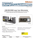
LSM-6900
Laser Scan
Micrometer
(Display Unit)
User's Manual
Read this User’s Manual thoroughly
before operating the instrument. After reading,
retain it close at hand for future reference.
CONVENTIONS USED IN USER'S MANUAL
Safety Precautions
To operate the instrument correctly and safely, Mitutoyo manuals use various safety signs (Signal
Words and Safety Alert Symbols) to identify and warn against hazards and potential accidents.
The following signs indicate general warnings:
DANGER
WARNING
Indicates an imminently hazardous situation which, if not avoided, will result in serious
injury or death.
Indicates a potentially hazardous situation which, if not avoided, could result in serious
injury or death.
Indicates a potentially hazardous situation which, if not avoided, may result in minor or
moderate injury or property damage.
CAUTION
The following signs indicate specific warnings or prohibited actions, or indicate a mandatory action:
Alerts the user to a specific hazardous situation. The given example means “Caution,
risk of electric shock”.
Prohibits a specific action. The given example means “ Do not disassemble”.
Specifies a required action. The given example means “Ground”.
i
No. 99MBC071A
CONVENTIONS USED IN USER'S MANUAL
On Various Types of Notes
The following types of notes are provided to help the operator obtain reliable measurement data
through correct instrument operation.
IMPORTANT • An important note is a type of note that provides information essential to the completion
of a task. You cannot disregard this note to complete the task.
• An important note is a type of precaution, which if neglected could result in a loss of
data, decreased accuracy or instrument malfunction/failure.
NOTE A note emphasizes or supplements important points of the main text. A note supplies information that may only apply in special cases (e.g.. Memory limitations, equipment configurations, or details that apply to specific versions of a program).
TIP A tip is a type of note that helps the user apply the techniques and procedures described in
the text to their specific needs.
It also provides reference information associated with the topic being discussed.
Mitutoyo assumes no liability to any party for any loss or damage, direct or indirect,
caused by use of this instrument not conforming to this manual.
Information in this document is subject to change without notice.
© Copyright Mitutoyo Corporation 2002. All rights reserved.
NOTES FOR EXPORTING
IMPORTANT For exporting this product, be sure to contact our office.
No. 99MBC071A
ii
PRECAUTIONS
1. Safety Precautions
The Measuring Unit connected to the Display Unit uses a very low power laser.
Use of controls or adjustments or performance of procedures other than those
specified herein may result in hazardous radiation exposure.
CAUTION
1) The IEC standard provides for two classes of laser product: a Class 2 laser product uses
a visible laser (maximum power: 1.5 mW for scanning; laser device: semiconductor
laser; wavelength: 650 nm).
2) Do not look directly into the laser beam. (Even if it seems that no light is being emitted
from the emission window, do not look into it.)
3) Do not stare the laser beam directly through optical instrument, such as a magnifying
lens.
4) If measuring flat objects with mirror finishes, avoid looking at the reflection on the
surface.
5) Close the beam shutter when the instrument is not in use.
6) Do not remove the laser class identification labels attached to the Measuring Unit.
7) Before using this unit, carefully read the “Measuring Unit Specifications” and “Precautions on Use of Laser” sections provided in the manual supplied with the Measuring
Unit.
CAUTION
LASER RADIATION-DO NOT
STARE INTO BEAM
1.5mW(peak) SCANNING LASER
SEMICONDUCTOR LASER 650nm
CLASS 2 LASER PRODUCT
CAUTION
LASER LIGHT-DO NOT
STARE INTO BEAM
1mW-650nm
CLASS II LASER PRODUCT
IEC 60825-1 (1997-09)
2. Before making the connection between the Measuring Unit and the Display Unit, turn off the
power. If an optional device is to be connected to this system, make sure that the optional
device is also turned off.
3. Firmly tighten the screws of the cable connectors and interfaces to ensure shielding.
4. Do not touch the terminals of the connectors, otherwise contact may be poor.
5. Positively ground the Display Unit.
6. An error display may appear during operation. However, it may not always indicate a fault. If
an error display appears, consult the “Maintenance and Inspection” section.
Do not open the covers provided on the emission unit and reception unit.
iii
No. 99MBC071A
INSTALLING CONDITIONS
The Mitutoyo Laser Scan Micrometer is both a precision optical instrument and a precision
electronic instrument and this unit is the instrument suitable for indoor use as well. Therefore,
it must be carefully installed and the following conditions must be taken into consideration to
attain the highest possible accuracy.
1. Vibration
Install this unit if possible in a place where it will not be subject to vibration. If this unit is
used for a long period of time in an environment where there are significant vibrations, the
precision parts in this unit may be affected, resulting in the deterioration of measuring
accuracy.
If this unit has to be used in an environment where vibration is significant, measures such as
the laying of a vibration damping rubber pad under the unit must be applied to reduce the
effect of vibration.
2. Dust
Dust and airborne particles at the installation site adversely affect optical parts including the
protective glass and electronic parts of the Measuring Unit. Place this unit in a place with as
little dust and as few airborne particles as possible.
3. Direct sunlight
If this unit is subjected to direct sunlight, the heat may deform this unit and affect the
measuring accuracy.
If this unit must be placed by a window where it will be subjected to direct sunlight, protect
the unit by shading it.
4. Ambient temperature and humidity
This unit must be operated in an environment where the temperature is between 0 and 40˚C
and the humidity is between 35 and 85% RH. Avoid installing this unit where there is
significant temperature or humidity change.
Significant temperature and humidity changes may reduce measuring accuracy.
WARRANTY
In the event that the Mitutoyo Laser Scan Micrometer (LSM) should prove defective in
workmanship or material, within one year from the date of original purchase for use, it will
be repaired or replaced, at our option, free of charge upon its prepaid return to us.
If the unit fails or is damaged because of the following causes it will be subject to a repair
change, even if it is still under warranty.
1. Failure or damage due to inappropriate handling or unauthorized modification.
2. Failure or damage due to transport, droppage, or relocation of the machine after
purchase.
3. Failure or damage due to fire, salt, gas, abnormal voltage, or natural catastrophe.
This warranty is effective only where the machine is properly installed and operated following this manual.
No. 99MBC071A
iv
CONTENTS
CONVENTIONS USED IN USER'S MANUAL ................................................................. i
NOTES FOR EXPORTING ...............................................................................................ii
PRECAUTIONS ...............................................................................................................iii
INSTALLING CONDITIONS ........................................................................................... iv
WARRANTY .................................................................................................................... iv
v
1.
INTRODUCTION ................................................................................................... 1-1
1.1 Outline ........................................................................................................... 1-1
1.2 Foreword ....................................................................................................... 1-1
1.3 Nomenclature ................................................................................................ 1-2
1.3.1 Display Unit ....................................................................................... 1-2
1.3.2 Measuring Unit .................................................................................. 1-4
2.
SETUP .................................................................................................................. 2-1
2.1 Unpacking and Acceptance Check ............................................................... 2-1
2.2 Connecting the Cables ................................................................................. 2-1
2.3 Preliminary Checks ....................................................................................... 2-5
2.4 Initializing the LSM-6900 Display Unit .......................................................... 2-6
3.
DISPLAYS AND KEY OPERATIONS .................................................................. 3-1
3.1 Outline of the Operation Modes ................................................................... 3-1
3.1.1 Measurement Principle ..................................................................... 3-1
3.1.1.1 Overview ................................................................................. 3-1
3.1.1.2 Setting the segment ............................................................... 3-3
3.1.1.3 Measurement interval (measurement time) ........................... 3-4
3.1.2 Outline of the Operation Modes ....................................................... 3-5
3.1.2.1 Basic setup mode ................................................................... 3-6
3.1.2.2 Calibration mode .................................................................... 3-6
3.1.2.3 Measuring condition setup mode ........................................... 3-6
3.1.2.4 Other setup mode ................................................................... 3-6
3.1.2.5 Statistic display mode ............................................................. 3-6
3.1.2.6 Measurement mode ................................................................ 3-7
3.2 Techniques and Terminology of Setup Functions ........................................ 3-9
3.2.1 Program ............................................................................................ 3-9
3.2.2 Basic setup ....................................................................................... 3-9
3.2.3 Function setup ................................................................................ 3-10
3.2.4 Setups according to the property of each workpiece ..................... 3-10
3.2.4.1 Transparent object (Workpiece that transmits light) ............ 3-10
3.2.5 Latch (holding) of the displayed value ........................................... 3-10
3.2.6 Automatic measurement with an edge specification ...................... 3-11
3.2.7 GO/NG judgment ............................................................................ 3-12
3.2.8 Abnormal data elimination .............................................................. 3-14
3.2.9 Offset/Zero-set ................................................................................ 3-15
3.2.10 Mastering ........................................................................................ 3-16
3.2.11 Reference value .............................................................................. 3-16
3.2.12 Data output conditions .................................................................... 3-17
3.2.13 Automatic workpiece detection <Diameter detection method,
Position detection method> ............................................................ 3-17
3.2.14 Group judgment .............................................................................. 3-20
3.2.15 Recording the amount of light ........................................................ 3-21
No. 99MBC071A
3.3 Outline of the Display Contents ..................................................................
3.3.1 Display unit .....................................................................................
3.3.2 Data display unit .............................................................................
3.4 Outline of Key Operations ..........................................................................
3.4.1 Description of key functions ...........................................................
3.4.2 Example key operations .................................................................
4.
No. 99MBC071A
3-22
3-22
3-22
3-24
3-25
3-29
SETTING UP THE MEASURING CONDITIONS ................................................. 4-1
4.1 Basic Setup ................................................................................................... 4-1
4.1.1 Outline of the basic setup procedure ............................................... 4-2
4.1.2 Description of each mode ................................................................. 4-3
4.1.2.1 Selecting and setting the function in the B0 mode. ............... 4-4
a. Setting the resolution (Guidance: RES) ............................ 4-4
b. Setting the number of blank-out digits (Guidance: BLN) .. 4-5
c. Putting a comma after the thousandths digits
(Guidance: (,)) ................................................................... 4-5
d. Setting the buzzer function (Guidance: BUZZER) ............ 4-6
e. Setting the display latch timer (Guidance: LATCH) .......... 4-6
4.1.2.2 Selecting and setting the function in the B1 mode. ............... 4-7
a. Setting the output function in the ready state
(Guidance: D.OUT) ............................................................ 4-7
b. Setting the analog output voltage if Err-0 occurs
(Guidance: ERR-0 V) ........................................................ 4-7
c. Selecting the display message if Err-0 occurs
(Guidance: ERR-0 D) ........................................................ 4-7
d. Selecting the display message at the start of measurement
(Guidance: RUN D) ........................................................... 4-8
e. Selecting the averaging method (Guidance: AVG.M) ....... 4-8
f. Setting the GO/NG judgment method
(Guidance: JDG.M) ............................................................ 4-8
g. Setting whether the target value is copied to the
reference value (Guidance: COPY) .................................. 4-9
4.1.2.3 Selecting and setting the function in the B2 mode .............. 4-10
a. Setting the workpiece type (Guidance: WORK.P) .......... 4-10
b. Setting the simultaneous measurement
(Guidance: PROG) .......................................................... 4-10
c. Selecting the method of specifying segments
(Guidance: SEG) ............................................................. 4-11
4.1.2.4 Selecting and setting the function in the B3 mode .............. 4-12
a. Setting the abnormal value elimination function
(Guidance: ADE) ............................................................. 4-12
b. Setting the automatic workpiece detecting function
(Guidance: AWDT) .......................................................... 4-12
c. Setting the number of scans (Guidance: SCAN) ............ 4-12
d. Setting the group judgment (Guidance: GTJ) ................. 4-13
e. Setting the group judgment output (Guidance: GTJ D) .. 4-13
vi
4.2
4.3
4.4
4.5
5.
vii
4.1.2.5 Selecting and setting the function in the B4 mode ..............
a. Setting the use of RS-232C port (Guidance: RS-232C) .
b. Setting the RS-232C communication baud rate
(Guidance: BAUD) ...........................................................
c. Setting the RS-232C communication data bits
(Guidance: LENGTH) ......................................................
d. Setting the RS-232C communication parity bit
(Guidance: PARITY) ........................................................
e. Setting the delimiter for communication
(Guidance: DELIMT) ........................................................
f. Setting the RS-232C line control
(Guidance: CONTRL) ......................................................
4.1.2.6 Selecting and setting the function in the B5 mode ..............
a. Setting the RUN input function from the I/O interface
(Guidance: RUN) .............................................................
b. Setting the OFFS input function from the I/O interface
(Guidance: OFFS) ...........................................................
c. Setting the GO output function from the I/O interface
(Guidance: GO) ...............................................................
4.1.2.7 Selecting and setting the function in the B6 mode ..............
a. Setting the use of DCU (Guidance: DCU) ......................
Calibration ...................................................................................................
4.2.1 Calibration gages and gage stand .................................................
4.2.2 Entering the calibration mode .........................................................
Positioning a Gage or a Workpiece ............................................................
How to read-in the amount of light .............................................................
Setting Up the Functions ............................................................................
4.5.1 Outline of the function setup mode ................................................
4.5.2 Outline of each function setup mode .............................................
4.5.3 Function setup mode ......................................................................
4.5.3.1 F0: Setting the segment .......................................................
4.5.3.2 F1: Setting the measurement interval (measurement time)
4.5.3.3 F2: Setting the GO/NG judgment criteria .............................
4.5.3.4 F3: Setting the reference value ............................................
4.5.3.5 Analog voltage output and scale value ................................
4.5.3.6 F4: Setting the offset value ..................................................
4.5.3.7 F5: Setting the data output conditions .................................
4.5.3.8 F6: Setting the sample measurement ..................................
4.5.3.9 F7: Automatic workpiece detection setting ..........................
4.5.3.10 F8: Setting the group judgment ............................................
4.5.3.11 Confirming the function setup contents ................................
4-14
4-14
4-14
4-14
4-15
4-15
4-15
4-16
4-16
4-16
4-17
4-17
4-17
4-18
4-18
4-18
4-22
4-22
4-23
4-23
4-25
4-26
4-26
4-28
4-30
4-34
4-35
4-37
4-39
4-40
4-41
4-42
4-43
MEASUREMENT MODE ......................................................................................
5.1 Outline of the Measurement Mode ...............................................................
5.1.1 Settings made in the measurement mode .......................................
5.1.1.1 Setup operation from the arrow key .......................................
5.1.1.2 Setup that can be made directly from each setup item key ..
5.2 Other Functions ............................................................................................
5.2.1 Key lock ............................................................................................
5.2.2 Displaying the measuring position ....................................................
5-1
5-1
5-1
5-2
5-4
5-5
5-5
5-5
No. 99MBC071A
5.3 Applied Measurement ................................................................................... 5-6
5.3.1 Diameter measurement of a precision-machined workpiece ........... 5-6
5.3.2 Measurement of the lead pitch of a multiple-pin IC ......................... 5-7
5.3.3 Applied Measurement with Offset/Zero-Set Functions ..................... 5-9
5.3.4 Sample measurement ..................................................................... 5-12
5.3.5 Applied measurement with automatic workpiece detection ........... 5-14
5.3.6 Applied measurement on a stepped round bar .............................. 5-16
6.
No. 99MBC071A
INTERFACE UNIT ................................................................................................ 6-1
6.1 Standard Interface ........................................................................................ 6-1
6.1.1 I/O Analog Interface .......................................................................... 6-1
6.1.1.1 External view of the connector ............................................... 6-1
6.1.1.2 Terminal names ...................................................................... 6-2
6.1.1.3 Input/output equivalent circuit ................................................. 6-2
6.1.1.4 Timing chart ............................................................................ 6-5
6.1.2 RS-232C Interface ............................................................................ 6-7
6.1.2.1 Specifications .......................................................................... 6-7
6.1.2.2 Connections ............................................................................ 6-8
6.1.2.3 Printer interface .................................................................... 6-10
6.1.2.4 RS-232C/GP-IB commands ................................................. 6-10
6.1.2.5 List of commands ................................................................. 6-12
6.1.2.6 List of response commands if an error occurs .................... 6-14
6.1.2.7 Format of response commands ........................................... 6-15
6.1.2.8 Other commands .................................................................. 6-16
6.1.2.9 Details of command descriptions ......................................... 6-17
6.1.2.10 An example Program of RS-232C Communication ............. 6-25
6.1.2.11 An example Program of GP-IB Communication Control ..... 6-26
6.2 Optional Interface ........................................................................................ 6-27
6.2.1 Digimatic Output Unit interface ....................................................... 6-27
6.2.1.1 Method of use ....................................................................... 6-27
6.2.1.2 Name of each part ................................................................ 6-28
6.2.1.3 I/O specifications .................................................................. 6-29
6.2.1.4 Timing chart .......................................................................... 6-30
6.2.1.5 Data format ........................................................................... 6-31
6.2.2 Second Analog I/O Interface .......................................................... 6-33
6.2.2.1 Method of use ....................................................................... 6-33
6.2.2.2 Name of each part ................................................................ 6-33
6.2.2.3 I/O Interface .......................................................................... 6-34
6.2.2.4 Analog output ....................................................................... 6-43
6.2.3 BCD interface ................................................................................. 6-44
6.2.3.1 Method of use ....................................................................... 6-44
6.2.3.2 Name of each part ................................................................ 6-44
6.2.3.3 Specification ......................................................................... 6-45
6.2.4 GP-IB interface ............................................................................... 6-49
6.2.4.1 Method of use ....................................................................... 6-49
6.2.4.2 Name of each part ................................................................ 6-49
6.2.4.3 Specification ......................................................................... 6-50
6.2.4.4 Functions .............................................................................. 6-52
6.2.4.5 Operations ............................................................................ 6-53
viii
6.3 Installing the Optional Interface Unit .......................................................... 6-54
6.3.1 Digimatic Output Unit ...................................................................... 6-55
6.3.2 Second Analog I/O, BCD, and GP-IB interfaces ............................ 6-55
7.
INSPECTION AND MAINTENANCE .................................................................... 7-1
7.1 Display Unit ................................................................................................... 7-1
7.1.1 Display check .................................................................................... 7-1
7.1.2 Cleaning method ............................................................................... 7-1
7.2 Measuring Unit .............................................................................................. 7-2
7.2.1 Laser emission status indicator LED ................................................ 7-2
7.2.2 Cleaning optical parts ....................................................................... 7-2
7.2.3 Replacement of protection glass ...................................................... 7-3
7.3 Error Messages and Remedies .................................................................... 7-4
7.4 Troubleshooting and Remedies .................................................................... 7-5
7.5 Fuse replacement ......................................................................................... 7-6
8.
SPECIFICATIONS (DISPLAY UNIT) ................................................................... 8-1
8.1 LSM-6900 Display Unit ................................................................................. 8-1
9.
RESTRICTIONS ASSOCIATED WITH THE COMBINATION OF FUNCTIONS,
TABLES OF THE BASIC SETUP MODES ......................................................... 9-1
9.1 Restrictions Associated with the Particular Combination of Functions ........ 9-1
9.2 List of Setup Modes ...................................................................................... 9-3
9.2.1 List of basic setup modes ................................................................. 9-3
9.2.2 List of calibration functions ............................................................... 9-4
9.2.3 Reading in the amount of light ......................................................... 9-4
9.2.4 List of function setup modes ............................................................ 9-5
SERVICE NETWORK
ix
No. 99MBC071A
1
1.1
INTRODUCTION
This chapter describes the Laser Scan Micrometer (LSM) models and
nomenclature of the Display unit and the Measuring unit.
Outline
This system is an accurate, non-contact measurement system capable of measuring workpiece
dimensions at a high speed using a highly directional scanning laser beam.
This non-contact optical measuring system is capable of measuring workpieces which are
difficult to measure with conventional measuring instruments. It performs simple and
accurate measurement of brittle or elastic objects, objects at high temperature, objects which
must be kept clean, and soft objects which may be deformed and suffer dimensional changes
under the measuring forces used.
1.2
Foreword
The Measuring Unit LSM-902 is used for this Display Unit.
This user’s manual primarily explains the functions of the Display Unit. For information
about the safety precautions, specifications, dimensions, standard accessories, and options for
each Measuring Unit, refer to the user’s manual supplied with the LSM-902.
The Measuring Unit uses a laser. For safe operation, carefully read and follow the
“Safety Precautions on Use of Laser” section described in the user’s manual that is
WARNING supplied with each Measuring Unit.
No. 99MBC071A
1-1
1.3
Nomenclature
This section gives the name of each part in the LSM system.
1.3.1
(1)
Display Unit
Front panel
Operation keys
Data display
Mitutoyo
LASER SCAN MICROMETER
LSM-6900
SHIFT
RUN
C.RUN
S.PR
PRINT
SET
READ
7
8
9
C
H.CAL
4
5
6
LIMIT
PROG.
LOCK
LASER EMISSION
CAL
-NG
GO
OFFSET
+NG
S.E
DUAL
L.CAL
1
2
3
MASTER
OFFSET
0
•
+/-
REF
STAT
S.E
ENT
RUN BUSY
LOCK A.CL
UNIT M.CL
Status indicator LEDs (lit/unlit)
Workpiece position indicator LED
Power switch
Stand
(2)
Displays and keys
1-2
SHIFT
RUN
C.RUN
S.PR
PRINT
SET
READ
7
8
9
C
H.CAL
4
5
6
LIMIT
L.CAL
1
2
3
MASTER
OFFSET
0
•
+/-
REF
LOCK
UNIT
A.CL
M.CL
STAT
S.E
ENT
No. 99MBC071A
1. INTRODUCTION
(3)
Rear panel
Optional Interface add-on space
(Second Analog I/O Unit, BCD Output Unit, GP-IB Unit)
Optional Digimatic Output Unit
add-on space
Name plate
AC power inlet
FOOT
SW.
SCAN SIG.-1
ID UNIT 1
Fuse holder
ID
TRANSMITTER-1
REMOTE INTERLOCK
RS-232C
I/O ANALOG
AC power inlet
Foot switch
Analog I/O connector
ID Unit Protection cover
Signal cable connector
Scanning signal connector
Remote interlock connector
RS-232C connector
TIP 1. A label which describes the terminal block name “I/O ANALOG” can be seen if the
protective cover of the Analog I/O terminal block is opened. Use this for wiring.
2. The terminal located at the left end of the power input terminal and marked (by a
symbol
or
) is the grounding terminal to keep the potential of signal line of
this unit equal with other instrument connected. It is used to enhance resistance
against electrical interference.
IMPORTANT Precautions for wiring the terminal block
1. If wiring the I/O analog terminal and Power input terminal, do not directly touch the
output terminals of the terminal block by hand, which has static charges, because
the internal circuit may be damaged by static discharge.
If your hands are charged, discharge the static energy by touching the metallic
surface of the Display Unit in advance. In addition, unplug the power cable from
the outlet before commencing wiring.
2. After wiring has been completed, close the protective cover.
3. Do not touch the input terminals on the terminal block during operation, otherwise
an operation error may result.
No. 99MBC071A
1-3
1.3.2
Measuring Unit
Emission window
Shutter
Laser emission
indicator LED
Signal cable
Serial number label
1-4
Reception window
Reception unit
Emission unit
No. 99MBC071A
2
2.1
SETUP
This chapter describes the connection between the Display Unit and
Measuring Unit.
Unpacking and Acceptance Check
Your LSM has been thoroughly inspected prior to shipment. The mechanical, electrical, and
optical systems are guaranteed to operate properly.
Unpack the package and check that the accessories, for the Display Unit or Measuring Unit,
and signal cables, etc., are intact and not damaged.
Contact Mitutoyo if anything is damaged or missing.
2.2
Connecting the Cables
Make sure that the power switch is turned off (turn the key switch counterclockwise to align
with “O”, then pull it out), then connect the cables according to the following procedure.
Step 1: Integrating the option interface
For the option interface (Second Analog I/O Unit, BCD Output Unit, GP-IB Unit,
and Digimatic Output Unit) to become available with the LSM, it must be installed
by referring to Chapter 6.3 “Installing the Optional Interface Unit”.
For information about the setup switches on the BCD and GP-IB interface units refer
to Section 6.2.3, “BCD Interface” and Section 6.2.4, “GP-IB Interface”, respectively.
No. 99MBC071A
2-1
Step 2: Attaching the ID unit
1. Loosen the two screws that secure the ID unit protection cover at the left on the
real panel of the Display Unit and remove the cover by sliding it rightward.
2. Remove the dummy ID unit (amber) that has been mounted at the left of the
“TRANSMITTER-1” connector on the rear panel of the Display Unit, then insert
the ID unit (beige) that comes in the same package as the Measuring Unit.
This ID unit stores critical data that ensures the accuracy of the Measuring Unit
and has the same serial number as the accompanying Measuring Unit. Confirm that
these two numbers are identical before inserting the ID unit.
ID unit slot
ID UNIT 1
SCAN SIG.-1
TRANSMITTER-1
ID
REMOTE INTERLOCK
ID unit
Serial number
label
ID unit
Measuring unit
3. Replace and secure the ID unit protection cover reversing the procedures in step 1
above.
2-2
No. 99MBC071A
2. SETUP
IMPORTANT • If the dummy ID unit is still mounted, “
”
is displayed in the lower section of the display. If
this is the case, turn off the power and replace the
dummy ID unit with a proper ID unit.
PROG
• If the ID unit is not installed or if the serial number of PROG
the Measuring Unit is not consistent with that on the
ID unit, the system will not work and an error code
as shown at the right will be displayed at power on.
At the same time, the 6-digit serial number of the
measuring unit is displayed for confirmation.
If the C key has been pressed to enter the ready state, measurement can be
automatically started. However, the measuring accuracy can not be guaranteed.
Power cord
ID unit
Signal cable
GND lead wire
Remote interlock
Step 3: Connecting the signal cable
Insert the round plug (12-pin) of the signal cable into the upper connector (12-pin)
on the rear panel of the emission unit. Tighten the ring screw to firmly secure the
connectors.
Insert the square connector (15-pin) on the other end of the signal cable into the
connector “TRANSMITTER-1” at the upper left of the display rear panel and tighten
the securing screws.
Step 4: Connecting the power cord and GND lead wire
Connect the supplied power cord to the AC connector at the upper right on the rear
panel of the Display unit. Also be sure to ground the Display unit with the GND lead
wire for improved resistance to noise.
Grounding must be done properly:
Connect the supplied grounding wire, after cutting it to the minimum length, to the
grounding terminal provided on the Display Unit. This unit operates as a precision
analog processor and, at the same time, a high-speed calculation unit. To enhance
resistance against electrical interference and to increase safety, do not neglect
grounding.
No. 99MBC071A
2-3
Step 5: Checking the remote interlock connector
Make sure that the short-circuiting pin is inserted into the “REMOTE INTERLOCK”
connector on the rear panel of the Display Unit. If this short-circuiting pin is not
inserted, laser emission is disabled, even if the power switch is on.
To emergency stop laser emission, refer to the following diagram.
Switch ON: Laser emission ON
Switch OFF: Laser emission OFF
Short-circuiting pin
Switch
5V, 3mA
Applicable connector: PJ-2
(Manufacturer: Sato Parts)
Step 6: Connecting the interface
For information about the procedure used to connect the interface, refer to Section
6.1.1, “I/O Analog Interface” and Section 6.1.2, “RS-232C Interface”.
IMPORTANT 1. Note the following when connecting the signal cable.
For information about the precautions to be observed when connecting the signal
cable refer to the external view and dimensions in the Section 8.1, “LSM-6900
Display Unit”.
2. Note the following when making cable connections.
Always make connection or disconnection with the power cord unplugged. In
addition, before connecting to the interface make sure that the power to all other
units connected or to be connected are also off.
Do not disassemble this unit. This unit is a precision instrument. Should it be disassembled by the user, its accuracy can not be guaranteed even within the term of its
warranty. And, there will be a charge for repairs.
Observe the following to avoid electric shock.
1. If an optional interface needs to be installed inside the Display Unit, unplug the
power cord from the inlet and put the power switch in the OFF position, then pull
off the key switch.
2. Do not remove the protective cover on which the seal is stuck to. Otherwise, an
electric shock may result.
3. Do not remove the seal, shown at the left.
2-4
No. 99MBC071A
2. SETUP
2.3
Preliminary Checks
The necessary connections should be completed by following the procedure described in the
previous chapter. Simplified operation checks are described here.
Step 1: Fully open the lens cap and shutter of the Measuring Unit.
Fully open the lens caps and beam shutters of both the emission unit and reception
unit to ready the laser beam for emission.
The lens caps should be completely removed, and the shutters should be as shown in
the diagram below.
Emission window
Shutter window
Shutter
If the shutter is closed
If the shutter is open
Step 2: Power on
• Turn the power key switch on the Display Unit clockwise until it is in the I
(power on) position and the power is on.
• This unit enters the self check mode and all the LEDs and segments turn on. They
will be displayed in the upper display section.
will turn off shortly, and eights
When
is displayed across the upper display section, the unit will
turn off shortly. This is followed by the self check on the lower display section.
PROG
PROG
• In the lower display section eights will appear sequentially from the left to
right.
• After
is displayed across the lower display section, it will
turn off shortly.
PROG
PROG
• Measurement is started.
The LASER EMISSION LED turns on and the BUSY LED starts flashing to
indicate the measurement has started from the ready state.
Since the objective segment has been set to
“SEG 1” at the factory, the displayed measurement shows the laser scanning range of the
Measuring Unit.
PROG
Here, the Display Unit is found to be normal
because the scanning range is displayed.
Proceed to Chapter 3, “DISPLAYS AND KEY
OPERATIONS”, to custom set up each
function.
No. 99MBC071A
2-5
• An error may be displayed at this stage,
PROG
however, the display at the right is not actually
an error. Check the shutter of the Measuring
Unit.
For information about other errors that may result refer to Section 7.3, “Error
Messages and Remedies”.
2.4
Initializing the LSM-6900 Display Unit
After making sure that this unit is operating normally, initialize the Display Unit so it can
recognize the Measuring Unit(s) to be used.
Initialization of the Display Unit is also required if the Measuring Unit needs to be changed.
In addition to replacing the ID unit that is associated with the Measuring Unit, initialize the
Display Unit (i.e. restore the factory setups) with the following procedure.
The initialization procedure is as follows:
Step 1: Turn off the power and connect the Measuring Unit with the ID unit that comes with
the Measuring Unit installed.
Step 2: Turn on the power while holding down the C key.
Hold down the C key for approximately 2 seconds, even after the power is on.
Step 3: When the self check has been completed, the
PROG
display shown at the right will appear. To initialize, press the ENT key. When the initialization
process has been completed, the display restors
the initial conditions that existed just after the
power on.
To abort initialization press a key other than the ENT key or turn the power off.
In the former case the initialization process will be aborted and the initial display at
power-on will be restored.
IMPORTANT Initialization will clear all the customer setup data and will restore the factory-setups.
Customize the setups again as necessary.
2-6
No. 99MBC071A
3
DISPLAYS AND KEY
OPERATIONS
This Display Unit is provided with many useful functions that can be
customized according to the user's needs.
This chapter describes these functions and key operations.
3.1
Outline of the Operation Modes
3.1.1
Measurement Principle
In order for the user to understand the measurement principle of the LSM, the following
paragraphs describe about the system block diagram, segments (measurement positions) and
measurement interval (measurement time).
3.1.1.1 Overview
Unlike light emitted from natural sources, a laser provides extremely fine, rectilinear beams
which do not diffuse (coherent light beams).
Using the properties of the laser beam, the Mitutoyo Laser Scan Micrometer (LSM) moves a
scanning laser beam over the workpiece and determines its dimensions by measuring the
duration in which the beam is obstructed by the workpiece.
Workpiece
Emission unit
Motor
Colimator lens
Reception unit
Condenser lens
Polygon mirror
Reception
device S
Polygon mirror
Laser power source
MP
Photoelectric element
(reset signal generation)
Semiconductor laser
Amplifier
RS
Motor driving pulse
Clock pulse
ROM RAM
t
Counter
t
Gate
t
Segment
selection circuit
Edge signal
Edge signal
RS
CPU
Data display
Keyboard
No. 99MBC071A
RS-232C
I/O analog
interface
Foot switch
Option I/F
3-1
The configuration of the system is shown in the above block diagram. A laser beam emitted
from the laser oscillator is directed at the polygon mirror which rotates at high speed and is
synchronized by clock pulses. The laser beam that is reflected by the polygon mirror is then
collimated by the collimator lens towards the workpiece. As the polygon mirror rotates, this
horizontal beam scans the workpiece and the beam not obstructed by the workpiece will
reach the photoelectric element through the condenser lens and induce an output voltage in
the photoelectric element. The output voltage will change according to the duration over
which the laser beam is obstructed. Counting pulses generated during that period are used to
determine the dimension of the obstructed portion. This data is sent to the CPU for processing and the dimensions are displayed digitally.
Consequently, either the dimensions of the workpiece (shadowed areas) or workpiece
clearances (highlighted areas) can be determined by specifying the segments to be measured.
TIP In the system block diagram described in the previous page, the laser beam passed
through the collimator lens is made parallel and, at the same time, stopped down so
that the beam diameter is minimized at the measurement position.
3-2
No. 99MBC071A
3. DISPLAYS AND KEY OPERATIONS
3.1.1.2 Setting the segment
Set the objective portion of a workpiece to be measured.
The highlighted and shaded portions created when the laser scans over the workpiece are
controlled with each assigned number. In the basic setup a selection must be made from one
of two cases: case where there are 1 to 4 highlighted and shaded sections, and case where
there are 1 to 127 similar sections. In the former case the portions are controlled through the
segment number, and are simply called segments. In the latter case the portions are controlled
by the edge number (edge number is between 1 and 255) and called edges. Edge numbers
equal to or greater than 256 are not available.
Segment specification
Edge specification
Highlight 1
SEG1
Highlight 1
Shade 1
SEG2
Shade 1
Highlight 2
SEG3
Shade 2
SEG4
Highlight 3
SEG5
Shade 3
SEG6
Highlight 4
SEG7
EDGE2
Direction of laser scanning
Direction of laser scanning
EDGE1
EDGE3
Highlight 2
EDGE4
Shade 2
EDGE5
Highlight 127
EDGE254
Shade 127
EDGE255
Highlight 128
EDGE256
• A maximum of 4 highlighted sections and a
maximum of 3 shaded sections can be measured.
• Multiple segments can be specified at the same
time.
• Specify segments 1 to 3 for a transparent object.
No. 99MBC071A
• A maximum of 127 highlighted sections and a
maximum of 127 shaded sections can be measured.
• Always specify the start edge and finish edge
numbers. These two edges can be either continued or separated. However, they must not be
identical.
• Edge numbers can not be specified for a transparent object.
• If automatic measurement is specified in the basic
setup, intervals, outside diameters, or gaps
between the same shape of multiple pins can be
automatically measured.
3-3
3.1.1.3 Measurement interval (measurement time)
A measurement interval (measurement time) varies depending on the averaging method and
the number of scans selected for the measurement data.
There are two types of averaging method: the arithmetical average and the moving average.
Select the one best suited for the user’s purpose.
1)
Arithmetical average
• If a moving workpiece is measured, the diameter of the workpiece is determined by
averaging the measured data taken from each section (a: first measurement, b: second
measurement, .... n: nth measurement) of the workpiece the specified number of averaging
times, as shown below.
first measurement
second measurement
...
a
b
nth measurement
n
Moving direction
Moving workpiece
• One of the following number of averaging times can be selected: 1, 2, 4, 8, ....1024, 2048.
• This is suitable for measuring a still object or the run-out of rollers, etc.
2)
Moving average
In the moving average method, a measurement interval identical to that in the arithmetical
average is divided into finer sections such as a1 (1st measurement), a2 (2nd measurement), - - , an (nth measurement). Each measurement is performed almost in parallel. If, for example, the number of averaging times is set to 512, the first measurement requires the
amount of time that corresponds to 512 scans. However, for the second measurement onward,
only the time for 16 scannings is required. With respect to a workpiece with a changing
diameter, this method provides data with smooth variation because of the many pieces of
data, and also quickly detects the trend of workpiece diameter variation.
Measurement with
Measurement with
arithmetical averaging arithmetical averaging
an
...
a2
...
an measurement
a2 measurement
a1
a1 measurement
Moving workpiece
Moving direction
Output of an measurement
Output of a2 measurement
Output of a1 measurement
• One of the following number of scans can be selected: 32, 64, 128, ....1024, 2048.
• This method is suitable for the feedback control of wire drawing machines and extruding
machines.
3-4
No. 99MBC071A
3. DISPLAYS AND KEY OPERATIONS
3.1.2
Outline of the Operation Modes
The LSM system has the following modes:
1: Basic setup mode, 2: Calibration mode, 3: Function setup mode, 4: Other setup mode, 5:
Statistical result display mode, and 6: Measurement mode.
Power ON
Error check
Power ON +
SET
SET
1 : Basic setup mode
6 : Measurement mode
LOCK
UNIT
,
LOCK
UNIT
SHIFT
H.CAL
Ready state
,
L.CAL
4: Other setup mode
2 : Calibration mode
RUN
ENT
SHIFT
(
LOCK
UNIT
)
C.RUN
Measurement in progress
(Program being executed)
• Single-run measurement
• Continuous-run
• measurement
S.PR
PRINT
(
5 : Statistical result
display mode
RUN
( H.CAL ,
ENT
L.CAL
)
C
•
SET
•
LIMIT
,
SHIFT
MASTER
OFFSET
,
,
REF
)
3 : Function setup mode
Measured data display
(Latched display)
SET
S.PR
( PRINT
)
• Latch timer
•
No. 99MBC071A
,
C
•
SET
•
ENT
(
LIMIT
,
MASTER
OFFSET
,
REF
)
3-5
3.1.2.1 Basic setup mode
• This mode is used to customize the basic setup conditions, including the resolution,
interface conditions, and available functions, according to the measurement requirements.
For more information, refer to Section 4.1, “Basic Setup”.
• To enter the basic setup mode turn on the power (turn the key switch clockwise from the
“O” position to the “I” position) while holding down the SET key. Hold down the SET
key for about 2 seconds to initiate the basic setup mode.
3.1.2.2 Calibration mode
• Depending on the environment in which the LSM is used and the Display Unit - Measuring Unit combination, measurement errors may result. Therefore, always perform calibration prior to use, taking the measuring range and environmental conditions into account.
If calibration is performed, the errors described above will be reduced and high accuracy
will be ensured.
• Before performing calibration, always make the setups for resolution, simultaneous
measurement, and available segments in the basic setup mode. If this order is reverse, the
previously set calibration values may be discarded.
• For more information, refer to Section 4.2, “Calibration”.
• Press the H.CAL key to enter the HI CAL mode; and press the L.CAL key to enter the LOW
CAL mode.
3.1.2.3 Measuring condition setup mode
• This mode is used to set up measuring conditions, including segments (objective portion of
workpiece to be measured) and GO/NG judgment criteria.
• Press the SET key to enable all the function setup items established to be set in a batch.
• Each of the LIMIT , SHIFT , MASTER / OFFSET , and REF keys allows the individual function
setup item to be established.
• Press the
key to enter the setup operation for the setup item which is used most
often.
3.1.2.4 Other setup mode
• This mode is used to set the key lock and to set the unit of measurement.
• Press the SHIFT and LOCK / UNIT key to turn on and off the key lock; and press only the
LOCK / UNIT key to enter the unit change mode.
• Press the SHIFT and READ key to enter the measuring position display mode.
3.1.2.5 Statistic display mode
• Displays the statistical processing results.
• Press the SHIFT and STAT / S.E keys in the ready state to enter the statistic display mode.
• Press the SHIFT and S.PR / PRINT keys in the ready state to allow the statistical processing
results to be printed.
3-6
No. 99MBC071A
3. DISPLAYS AND KEY OPERATIONS
3.1.2.6 Measurement mode
This mode can be divided into the following operational states:
1) Measurement in the ready state
• This is the measurement mode that is entered immediately after the power is turned on
or if another measurement mode is aborted by pressing the C key (or by the RESET
signal from the I/O interface or the “CL” command from the RS-232C/GP-IB interface).
• It is used to establish setups for calibration and available functions, which are not part
of the basic setup items, or to enter another measurement mode including single-run
measurement.
• Usually GO/NG judgment and analog output will not take place for measurement in the
ready state, however, these specifications can be made in the basic setup mode.
• Measurements in the ready state are unavailable for statistical processing.
2) Single-run measurement
• If the RUN key (otherwise input RUN via the I/O interface or “R” command via the
RS-232C/GP-IB interface) is pressed, one session of measurement is performed and the
results will be automatically subject to GO/NG judgment and analog output. In addition,
the measured data will be outputted for the RS-232C/GP-IB interface, Digimatic Output
Unit, and printer. The measured data will be held (latched for the specified period) in
the display.
• This data will be available for statistical processing.
3) Continuous-run measurement
• If the C.RUN key (otherwise input RUN+RESET via the I/O interface or “CR” command
via the RS-232C/GP-IB interface) is pressed, one session of measurement is started and
repeated the specified number of times. The measured data will be automatically subject
to GO/NG judgment and analog output. In addition, the measured data will be outputted
for the RS-232C/GP-IB interface, Digimatic Output Unit, and printer.
• Press the RUN or C.RUN key (or if RUN is received from the I/O interface) again to
terminate the measurement and hold the measured data on the display. If the C key
(or input RESET via the I/O interface or “CL” command via the RS-232C/GP-IB interface)
is pressed halfway, the measurement is aborted and the ready state is returned to.
• The measurements are available for statistical processing.
4) Continuous measurement with a term specification
• This will take place where RUN input from the I/O interface has been assigned so as to
start a term-specified continuous-run measurement in the basic setup.
• Repeatedly performs single-run measurement while RUN signal input continues, which
is basically the same as the continuous-run measurement. Therefore, hereafter, continuous-run measurement includes the ones with a term specification.
• The measurements are available for statistical processing.
No. 99MBC071A
3-7
5) Zero-run measurement
• A measurement where the number of samples is set to “0” is called a “zero-run measurement”.
• If the RUN key (otherwise input RUN via the I/O interface or the “R” command via
the RS-232C/GP-IB interface) is pressed, single-run measurement is started and
repeated until the RUN key is pressed again (or RUN is inputted via the I/O interface
or the “STOP” command is inputted via the RS-232C/GP-IB interface). From the
measured data the calculation items (mean, maximum value, minimum value, and
range) that have been set for the sample measurement will be calculated and the
resulting data will be automatically subject to GO/NG judgment and analog output. In
addition, the measured data will be outputted for the RS-232C/GP-IB interface,
Digimatic Output Unit, and printer. The measured data will be held on the display.
• The measured data are available for statistical processing.
• This is suitable for run-out measurement and cylindricity measurement.
6) Sample measurement
• A measurement where the number of samples is set to “2~999” is called a “sample
measurement”.
• In practice this will take place as a single-run measurement or a continuous-run measurement (with a term specification).
From the measured data the calculation items (mean, maximum value, minimum value,
and range) that have been set for the sample measurement will be calculated and the
resulting data will be automatically subject to GO/NG judgment and analog output. In
addition, the measured data will be outputted for the RS-232C/GP-IB interface,
Digimatic Output Unit, and printer.
• The measured data are available for statistical processing.
• This is suitable for run-out measurement and cylindricity measurement.
7) Statistical processing
• Measured data from single-run and continuous-run measurements can be statistically
processed (i.e. the number of measurement times, standard deviation, maximum value,
minimum value, mean, and range are calculated).
These statistical processing results can be outputted for the display, printer (statistical
memory for all programs will be cleared after printout), and RS-232C/GP-IB interface.
• Press the STAT / S.E key (or input “ST” command via the RS-232C/GP-IB interface)
to start statistical processing, and press it again (or input the “NST” command via the
RS-232C/GP-IB interface) to terminate statistical processing.
• Press the A.CL / M.CL key to clear the statistical memory of the foreground program
(case of a simultaneous measurement), and press the SHIFT and A.CL / M.CL keys to
clear the statistical memory of all the programs.
• These statistical results data will be stored in memory while the power is on, and will
be lost when the power is turned off.
3-8
No. 99MBC071A
3. DISPLAYS AND KEY OPERATIONS
3.2
Techniques and Terminology of Setup Functions
3.2.1
Program
• A measurement will automatically be performed according to the registered (programmed)
contents including the segment (feature to be measured) and GO/NG judgment criteria,
etc., in advance. Registration is performed in the function setup mode.
• This unit can hold a maximum of 10 programs, which may include various settings
suitable for up to ten kinds of workpieces.
• The user can select, in the basic setup, whether these ten programs are used as individual
programs (referred to as “single measurement”) or as five pairs of programs (referred to as
“simultaneous measurement”).
a) Single measurement
One session of measurement is performed according to the one specified program.
This is the factory default.
b) Simultaneous measurement
• In one measurement session two programs are executed at one time as a pair. These
pairs are formed as shown in the figure below.
• To run a pair of programs, either of the two can be specified via numeric keys 0
to 9 and the one specified is called “foreground” program, and its counterpart is
called “background” program.
Pair 4: Program No.4
No.9
Pair 3: Program Program
No.3
No.8
Pair 2: Program Program
No.2
No.7
Pair 1: Program Program
No.1
No.6
Pair 0: Program Program
No.0
Program No.5
3.2.2
Basic setup
• This is used to customize the basic setup conditions, including the resolution, available
functions, and interface conditions, according to the measurement requirements.
• This basic setup must be performed at the beginning of a measurement. Note that changing
the setup of resolution or simultaneous measurement in this basic setup cancel the existing
calibration values and function setup.
• The basic setup mode is entered by turning on the power while holding down the SET
key.
Note that no response will be made to an I/O interface input and RS-232C/GP-IB command in the basic setup mode.
• For more information, refer to Section 4.1, “Basic Setup”.
No. 99MBC071A
3-9
3.2.3
Function setup
• Use this procedure to set up the conditions necessary for measurement.
For each program number register measurement conditions including the segment (part
feature to be measured), measurement interval (measurement time), and GO/NG judgment
criteria that are the best suited for the objective workpiece.
• To enter the function setup mode press the SET key in the ready state. Each of the
LIMIT , SHIFT + MASTER / OFFSET , and REF keys allows the individual setup item to be
established, and the
key enters the setup operation for items which are most
frequently accessed for set up.
• For more information refer to Section 4.5, “Setting Up the Functions”.
3.2.4
Setups according to the property of each workpiece
For measuring workpieces that transmit light or have a dimension smaller than the diameter
of the scanning beam it is critical to make setups that take into account the properties of the
workpiece.
3.2.4.1 Transparent object (Workpiece that transmits light)
a) Round bar
• Workpieces such as fiber optics and glass tubes are more or less transparent, while
workpieces made of steel are not. This requires different segment settings.
The segment settings for an opaque object and a transparent object are as follows:
• Setup for measurement of transparent or opaque object is possible in the basic setup.
Photo-electric signal
Laser scan direction
Segment 1
Transparetnt
Workpiece
Segment 1
Segment 2
Segment 3
Segment 2
Segment 4
Segment 5
For opaque mode
Segment 3
For transparent mode
Binary voltage (SHL)
b) Plate (Sheet)
• If the workpiece being measured is a transparent plate (sheet) with edges that are not
chamfered or beveled, measurement may be aborted because there is not a sharp
contrast in the amount of light at the transition from the highlighted portion to the
shaded portion.
3.2.5
Latch (holding) of the displayed value
• In a single-run measurement, etc., GO/NG judgment and analog output will be continued
while the measured data is latched (held) on the display for the specified period of time.
After the set period elapses, system operation returns to the ready state.
• Set up the display latch timer in the basic setup.
• While the display is being latched, inputs from the I/O interface or RS-232C/GP-IB are still valid.
3 - 10
No. 99MBC071A
3. DISPLAYS AND KEY OPERATIONS
3.2.6
Automatic measurement with an edge specification
• If the edge specification is made, it is possible to automatically measure IC or connector
leads with respect to their pitch (even intervals), outside diameter, or gap. This is suitable
for inspecting the IC lead bend, etc.
Outside
diameter
Gap
Pitch
Laser
scanning
direction
• This function is only in effect if the necessary setups are made for edge specification in
the basic setup.
• In the function setup designate whether automatic measurement should be performed (for
pitch/outside diameter/gap measurement) or not (manual measurement). Also designate
both the start and finish edges.
• This is available in combination with automatic workpiece detection.
• If automatic measurement has also been selected, the following will take place.
a) In the ready state the first objective portion of the workpiece to be measured will be
displayed.
b) Automatic measurement will be involved in a single-run measurement or continuousrun measurement.
If “Err-0” (insufficient number of edges to be measured) is detected, the measuring
operation is stopped for the single-run measurement, and the collected measured data is
cleared for continuous measurement to wait for a proper workpiece to be loaded.
c) If the measured data is found to be ±NG, the first source of the ±NG will be displayed
and the measuring operation is stopped. If GO results, the mean of all measurements is
displayed.
d) If the measured data falls within the range of GO, the elapsed measurement time was as
follows:
(Number of measurement edges) x (measurement interval) + (calculation time: 20 ms)
e) The W.P. LED shows the current portion of the workpiece being measured.
No. 99MBC071A
3 - 11
3.2.7
GO/NG judgment
• All the measured data are subject to GO/NG judgment.
To enable, set the GO/NG judgment criteria in advance.
• The following settings can be made in the basic setup.
a) The method of tolerance judgment can be selected from (Lower limit value and upper
limit value), multi-limit selection (7 limits) and (Target value and tolerance values:
upper tolerance value and lower tolerance value).
To output the judgment result with the multi-limit selection it is necessary to select the
optional Second Analog I/O Interface.
b) Simultaneous measurement can be specified. To do this, it is necessary to select the
optional Second Analog I/O Interface for tolerance result output.
c) For (Target value and tolerance values), the user is permitted to select whether the
target value is to be copied to the reference value. If it is, the setup guidance for the
reference value will not appear.
d) Even in the ready state it is possible to select whether tolerance judgment and analog
output are performed. If they are, tolerance judgment and analog output will take place
in the ready state, however, these data are not available for statistical processing.
e) Abnormal data elimination, tolerance judgment, group judgment, and analog output can
be performed in a single-run measurement, zero-run measurement, sample measurement, and continuous-run measurement (with a term specification). The judgment result
will be indicated by the -NG (red LED), GO (green LED), and +NG (red LED) indicators and outputted to the I/O interface and RS-232C (including printer)/GP-IB interface.
f) The following tables show the relationship between the measured data and tolerance
judgment method
1) (Lower and upper limit values)
GO/NG judgment
Measurement (judged if both the lower and upper limit values are set)
-NG
Measurement < Lower limit value
GO
Lower limit value ≤ Measurement < Upper limit value
+NG
Measurement ≥ Upper limit value
2) (Target value and tolerance values)
GO/NG judgment
3 - 12
Measurement (judged if the target value, lower tolerance value and upper
tolerance value are set)
-NG
Measurement < (Target value + lower tolerance limit)
GO
(Target value + lower tolerance value) ≤ Measurement < (Target value + upper
tolerance value)
+NG
Measurement ≥ (Target value + upper tolerance value)
No. 99MBC071A
3. DISPLAYS AND KEY OPERATIONS
3) If all limits from L1 to L6 are set for multi-limit selection
Multi-limit selection output
GO/NG judgment
L1
-NG
Measurement from L1 to L6 are set.
Measurement < L1
L2
GO
L1 ≤ Measurement < L2
L3
GO
L2 ≤ Measurement < L3
L4
GO
L3 ≤ Measurement < L4
L5
GO
L4 ≤ Measurement < L5
L6
GO
L5 ≤ Measurement < L6
L7
+NG
L6 ≤ Measurement
4) If only L1 and L2 are set for multi-limit selection
No. 99MBC071A
Measurement Only L1 and L2 are set.
(Judgment will not be performed if only one
stage is set.)
Multi-limit selection output
GO/NG judgment
L1
-NG
Measurement < L1
L2
GO
L1 ≤ Measurement < L2
L3 ~ L7
+NG
L2 ≤ Measurement
3 - 13
3.2.8
Abnormal data elimination
• The abnormal data elimination function eliminates measurements that are very different
from those specified for the machined workpiece, from the measurement data (neither the
measurement is displayed nor is data output performed).
If, for example, the grindstone of a centerless grinder is controlled based on the measured
data from the LSM, it is possible that a large measurement error may be created due to the
coolant used with the workpiece.
As shown in the figure below where foreign matter (with a height of h) adheres to within
the averaging region L of the workpiece (with a diameter of D). An abnormal outside
diameter results in the region of l and the displayed measurement will be (D + lh / L). As
the result the grinder is subject to improper control that involves some error.
L
l
D
h
Workpiece
Workpiece feed direction
Because the use of this function can eliminate abnormal measurement data generated due
to the adhered foreign matter, the grindstone can be controlled and fed properly.
• Judgment of valid data or abnormal data will be performed at each measurement interval.
Valid data includes those satisfy the following relation: Lower abnormal limit (Measurement) < Upper abnormal limit. All other data will be discarded as abnormal data.
• The following table shows the relationship between measurements and upper and lower
abnormal limits.
Eliminate/Do not eliminate
Measurement (Judged if both the upper and lower
abnormal limits are set.)
Eliminate
Measurement < Lower abnormal limit
Do not eliminate
Lower abnormal limit ≤ Measurement < Upper
(accepted as a measurement) abnormal limit
Eliminate
Measurement ≥ Upper abnormal limit
• In the basic setup select whether this abnormal data elimination function should be used. If
it is the setting of (lower abnormal limit, upper abnormal limit, and count value) should be
performed before actual tolerance judgment.
This count value indicates the number of pieces of abnormal data that occurred until the
alarm will be issued. This alarm output will be sent to the optional Second Analog I/O
Interface by CNT form (The alarm will not be issued if the count value is set to zero).
• Abnormal data elimination function effects in single-run and continuous-run measurements.
• If “Err-0” (specified workpiece not present) is displayed in the sample measurement, the
valid data collected will be discarded.
IMPORTANT If a long series of abnormal data appears, measurement can no longer be continued
since most of the measured data must be eliminated. To avoid this problem, always
monitor CNT output.
3 - 14
No. 99MBC071A
3. DISPLAYS AND KEY OPERATIONS
3.2.9
Offset/Zero-set
This function is used to measure the difference between the workpiece and the reference gage
or to measure the workpiece that is larger than the measuring range of the LSM.
a) Offset
• In this system the operation of setting the reference gage dimension is called the
offset operation.
• This function is applied to measure the absolute dimension of a workpiece.
b) Zero-set
• Setting the reference gage dimension to “0.0” for the purpose of comparing it with a
workpiece dimension is called the zero-set.
• This function is applied to measure a deviation from the reference gage dimension.
c) Direction
Depending on the objective portion of measurement of a workpiece, the positive
direction (set as “0”) or negative direction (set as “1”) must be set.
If, for example, the shaded portion of D in the following diagram is measured, the
direction must be set as positive (0). If the highlighted portion (gap) of W is to be
measured for determining the workpiece dimension L, the direction must be specified
as negative (1).
Set as positive (0)
Set as negative (1)
Reference piece
W
D
Workpiece
L
Workpiece
Reference plane
• Offset operation takes about 1 second to determine the compensation value by measuring
the reference gage.
• Offset value will be ineffective if the segment or edge number is changed (Offset value is
unique to each segment or edge).
NOTE • About the gap measurement.
If it is necessary to measure Segment 1 in such as a runout measurement, use a
reference pin or knife-edge at the focus position, as shown in the diagram below.
If this reference pin is not used, repeatability will be reduced.
Reference pin or knife-edge
SEG1
Workpiece
No. 99MBC071A
3 - 15
3.2.10 Mastering
• If the objective workpieces are high-precision gages that are machined successively, the
above described offset/zero-set values may need to be fine-adjusted to the master. This
fine-adjustment is called mastering.
After mastering, the total compensation value will be:
(Offset value/zero-set value) + (±Mastering value)
Setting a positive (+) mastering value allows the measurement of a workpiece diameter to
be greater than the raw measurement, and setting a negative (-) mastering value allows the
measurement of a workpiece diameter to be smaller than the raw measurement.
• Because no measurement is required for this mastering, the reference gauge is not required
either.
• Mastering will be cancelled if subjected to offset/zeroset.
• Set the reference gage dimension with the offset function and perform mastering.
3.2.11 Reference value
• This function is used to output deviations (measured data - reference value) between the
reference value and the actual measurements of a workpiece for the Analog I/O Interface.
Before analog output, set the reference value and the scale value (gain).
• Measured data is outputted as analog signals at a full scale of ±5V.
Analog signal = (Measured data - reference value) x scale value (gain)
• In the basic setup the following conditions can be set.
a) Whether the target value of GO/NG judgment is be copied to the reference value. If this
is selected, the setup guidance for the reference value will not be displayed, so only the
scale value must be set.
b) It is also possible to set so that tolerance judgment and analog output can take place in
the ready state.
• Analog output is automatically enabled if single-run measurement or continuous-run
measurement is performed.
• If the reference value is being set the deviation value will be output for the RS-232C/GPIB interface and the printer if single-run measurement or continuous-run measurement is
performed.
3 - 16
No. 99MBC071A
3. DISPLAYS AND KEY OPERATIONS
3.2.12 Data output conditions
• In single-run measurement or continuous-run measurement, measured data can be outputted for each measurement if ±NG occurs, or at given intervals to the RS-232C/GP-IB
interface, printer, or Mitutoyo Digimatic Output Unit.
Data output condition
RS-232C
GP-IB
DCU
Printer
0
—
—
1
—
2
—
Remark
The periodical output timer can be set
3
—
4
—
5
The periodical output timer can be set
The periodical output timer can be set
6
7
—
8
—
9
: Outputted for each measurement if RUN or C.RUN key, etc., is pressed.
: Press the RUN or C.RUN key to trigger the measurement. The measured data will be outputted if it falls on GO.
: Press the RUN or C.RUN key to trigger the measurement. The measured data will be outputted if it falls on ±NG.
— : No output will be made.
3.2.13 Automatic workpiece detection <Diameter detection method, Position detection
method>
• Automatic workpiece detection is performed for continuous-run measurement, where
measurement starts with no specified workpiece present (Err-0), then proceeds to automatic detection of the workpiece, followed by measurement repeated number of times. No
specified workpiece present (Err-5) also refers to the workpiece outside the upper and
lower detection limits.
• Whether automatic workpiece detection is performed is specified in the basic setup mode.
If automatic workpiece detection is specified, the number of scanning times for detection
must be specified from among 1 and 16. Select 16 times if detecting precision workpieces.
If automatic workpiece detection is not specified, no further setting is necessary.
• Automatic workpiece detection setup includes the number of measurement times, invalidation period, upper and lower detection limits. Both the upper and lower detection limits
may not always need to be specified, however, they should be set for safety.
• To exclude the measured data of such as chamfered portion of the workpiece, invalidation
period can be set within the range from 0.001 sec to 9.999 sec.
Start of
measurement
No. 99MBC071A
No workpiece
detected
Detection of
workpiece
Invalidation
elapses
Measured the specified
number to times
3 - 17
1) Diameter detection method
• This is used to automatically detect a workpiece that enters the laser scanning plane
perpendicularly.
• For actual detection of a workpiece the displayed measurement (after calibration and
offset) is used.
• One session of automatic detection consists of no workpiece being detected, detection of a workpiece with a dimension that is within the detection range (between the
upper and lower detection limits), an invalidation period required to exclude invalid
dimensions (of chamfered portions, etc.) from the measurement, and effective
measurement for the specified number of times. The final measurement result will be
latched (held) on the display. Once entering the effective measurement the upper and
lower detection limits will no longer be checked.
• The speed of workpiece detection (i.e. the number of scans) can be specified as
either 1 or 16 in the basic setup.
• Use 16 times in the following cases:
* If connecting bars are used between workpieces for feeding convenience and for
setting appropriate intervals between workpieces, and, if the difference in the
outside diameter between the workpiece and the bar is insufficient.
* If the feed rate is low.
• The following diagram is an example where a workpiece with a chamfered outside
diameter of D mm and a length of mm moves at a velocity of V mm/s.
Scanning beam
g
c
D a
Workpiece flow
V mm/s
Setting example:
• Lower detection limit: L < (a +D) / 2
• Upper detection limit: H > Upper limit of the measuring range or 1.1 D
(This setting may be omitted.)
• Invalidation period : T > (c / V) ms
• Number of measurements: N < ( - 2c) x 0.8 (safety factor) / measurement interval / V
3 - 18
No. 99MBC071A
3. DISPLAYS AND KEY OPERATIONS
2) Position detection method
• This is used to automatically detect a workpiece that enters the measuring region in
the laser scanning plane in the same direction of the scan.
• Workpiece detection is performed with one scan, and 16 scans can not be specified
(If specified in the basic setup, the specification will be ignored).
• One session of automatic detection consists of the detection of no workpiece,
detection of a workpiece edge with a dimension that falls within the detection range
(between the upper and lower detection limits), an invalidation period required to
exclude invalid dimensions from the measurement, and effective measurement for the
specified number of times. Once the effective measurement has been entered, the
upper and lower detection limits will no longer be checked.
• In the following diagram, workpiece positions (a) and (b) result in no workpiece
being present, and in (c) it is judged that a workpiece is present.
Detected edge
(a)
C
(c)
Laser scanning range
(b)
Measuring region
Upper detection limit: H
Laser scanning direction
Lower detection limit: L
Vmm/S
Setting example:
Assuming the workpiece diameter as D (mm) and the moving speed as V (mm/s):
• Lower detection limit: L > (Laser scanning range - measuring region) / 2
• Upper detection limit: H < (Laser scanning range + measuring region ) / 2 - D (This
setting may be omitted.)
• Invalidation period : Generally set to 0 ms.
• Number of measurements: N = 1
NOTE • Allow a sufficient margin for the lower detection limit, upper detection limit, invalidation period, and number of measuring times when setting them. If this surplus is
not sufficient, the measurement may not be achieved.
• If using the sample measurement, specify the number of measuring times to 1.
• The automatic workpiece detection functions in the continuous-run measurement.
No. 99MBC071A
3 - 19
3.2.14 Group judgment
• While the tolerance judgment is applied to each measurement from a workpiece, this group
judgment is applied to a group of the specified number of workpieces.
Judgment to Group 1
Judgment to Group 2
Judgment to Group 3
1
2
3
4
5
6
7
8
Individual
judgment
Individual
judgment
Individual
judgment
Individual
judgment
Individual
judgment
Individual
judgment
Individual
judgment
Individual
judgment
Output of
judgment
result 1
Output of
judgment
result 2
Output of
judgment
result 3
Output of
judgment
result 4
Output of
judgment
result 5
Output of
judgment
result 6
Output of
judgment
result 7
Output of individual
judgment result
Output of group judgment result
Output of judgment result 1
Output of
judgment result 2
• In the basic setup select whether group judgment is to be performed. If it is, then set the
group size (the number of workpieces included in a group), calculation items (mean,
maximum value, minimum value, and range), and group lower limit and upper limit. If
“Not performing group judgment” is selected, the setup guidance for it will not be displayed.
• The group judgment will be in effect in a single-run measurement or continuous-run
measurement.
a) For the result display and GO/NG judgment indication each individual measurement
and judgment result will be used.
b) Output of judgment result
1. If only the standard Analog I/O Interface is used
Each individual judgment result will be outputted.
2. If the second Analog I/O Interface is used
Each individual judgment result will be outputted for A-(+NG), A-(GO), and A-(NG), and the group judgment result will be outputted for B-(+NG), B-(GO), and B-(NG), respectively.
c) RS-232C/GP-IB output
In the basic setup it is possible to set whether the group judgment result data is outputted for the RS-232C/GP-IB interface. If it is, the output contents from the group
judgment will be as follows:
P0,
P0,
P0,
GP0,
( GO)
( GO)
(+NG)
( GO)
12.34567 ... Individual data
12.34560 ... Individual data
12.34600 ... Individual data
12.34575 ... Group judgment result data
• Each individual piece of measurement data can be the objective of statistical processing,
however, group measurement data will be excluded from statistical processing.
• Even if “Err-0” (specified workpiece not present) occurs, the obtained data will not be
cleared. To abort the measurement, press the C key (or input RESET via the I/O
Interface or the “CL” command via the RS-232C/GP-IB interface).
3 - 20
No. 99MBC071A
3. DISPLAYS AND KEY OPERATIONS
3.2.15 Recording the amount of light
• The gap measurement may be unstable if not enough laser beam passes through the gaps.
In the case shown in diagram (a) below, an adequate amount of light can be obtained as
the laser passes through gap (g) above the workpiece, even if the gap (t) is small. However, in diagram (b) where gap (t) is small, measurement will be affected. In this case,
therefore, it is necessary to have the system record the full amount of light when there is
no obstruction (workpiece or fixture) in the optical path.
g: Gap for the
reference beam
Laser beam
passes through
this gap.
Photo-electric signal
t
Gap
Workpiece
(a) Light amount can be detected normally = Auto-detecting
t
Workpiece
Gap
Light amount
can be detected
Peak of the
photo-electric
signal
Light amount
cannot be detected
(insufficient duration)
(b) Recording the amount of light is required
• Normally the amount of incident light is continuously checked so that the counting
operation can follow the change in the amount of incident light. To perform gap measurement with Measuring Unit LSM-902, gaps (g or t in the figure above) need to have 1mm
or larger width. If the gap does not have enough gap, have the system record the light
amount following 4.4, “How to read-in the amount of light”. It is also necessary to carry
out this operation twice or three times each year since the light amount of the system may
vary.
No. 99MBC071A
3 - 21
3.3
Outline of the Display Contents
Displays of this system are effected by the display unit and guidance LEDs.
3.3.1
Display unit
The name of each part of the display unit and the LEDs are given below:
Data display unit (fluorescent display tube)
PROG
Upper display section
Lower display section
Measurement state guidance
LOCK
CAL OFFSET
LASER EMISSION
S.E
DUAL
-NG GO +NG RUN BUSY
BUSY LED
RUN LED
GO/NG judgment LEDs
LD oscillation LED
W.P. (Work Position) LED
3.3.2
Data display unit
1) Numeric and character display
• Single measurement: Turns off.
• Simultaneous measurement:
Displays a background program number.
• Displays a settting item in the single measurement.
• Single measurement: Displays a setup value.
• Simultaneous measurement:
Displays the measured data of a background program.
• Displays the unit of measurement.
• Displays the measured
data of a foreground program.
• Displays a foreground program number.
2) Operation state guidance
• LOCK: Turns on in the key lock state, which is initiated by pressing both the SHIFT
and LOCK / UNIT keys. If these keys are input the key lock state will be
canceled.
• CAL:
Turns on if the calibration (HIGH CAL) is specified.
• OFFSET: Turns on if the offset function is active.
• S.E:
Turns on if statistical processing is activated.
• DUAL: Turns on if simultaneous measurement is specified.
3 - 22
No. 99MBC071A
3. DISPLAYS AND KEY OPERATIONS
3) Display LED
• W.P. (Work Position) LED
LED segments corresponding to a region shaded by the workpiece, which blocks the
laser beam, will turn off. This is used to check if the workpiece is located in the center
of the measuring region.
• LD oscillation LED
LASER EMISSION : Indicates that the laser in the Measuring Unit connected to the
“TRANSMITTER-1” connector is oscillating.
• GO/NG judgment LED
1. -NG : Turns on if the measured data is -NG.
2. GO : Turns on if the measured data is GO.
3. +NG : Turns on if the measured data is +NG.
• RUN LED
Turns on if a single-run measurement, continuous-run measurement or continuous-run
measurement with a term specification is performed.
• BUSY LED
Turns on each time the measured data is updated.
IMPORTANT Laser safety
For safety, the laser will not turn on until 5 seconds after the power is turned on. If
the power is unintentionally turned on, turn off the power within 5 seconds to secure
the laser.
No. 99MBC071A
3 - 23
3.4
Outline of Key Operations
On this system operate the keys as follows.
• The STAT / S.E key, for example, has two functions as PROG
indicated on the upper and lower portions of the key
top. The function on the upper portion can be activated
by simply pressing the key, and the one on the lower
portion can be activated by pressing the key while
holding down the SHIFT key. If the SHIFT key is
pressed, the currently displayed program number flashes
for about 10 seconds until another key is pressed.
During this period one of the functions in the upper
portions of the keys can be selected. Press the STAT /
S.E key while the program number is flashing.
• To enter the reference gage values, such as HIGH CAL, LOW CAL and offset, or other
setup values such as reference values and GO/NG judgment criteria, etc., the numeric keys
( 0 to 9 , . , +/- ) and arrow keys (
,
,
and
) can be
used.
a) If a setup value entry is started with a numeric key and an arrow key is pressed halfway,
an operation error will result. The following example shows a case of an offset value.
1. Enter the setup mode of the offset function.
The least significant digit of the existing offset value
is flashing.
PROG
2. Change the value to 12.00 mm.
Press the 1 key.
PROG
3. If an arrow key is pressed at this point, an operation
error occurs, however the display does not change.
PROG
4. To enable the entry of an arrow key, press the C
PROG
key to cancel the setup value.
Now the arrow keys are operable.
b) If a measurement is read as the setup data by pressing the READ key or if the entry of a
setup value is started with an arrow key and a numeric key is pressed halfway an operation
error will result. See the example above.
3 - 24
1. Enter the setup mode of the offset function.
The least significant digit of the existing offset value
flashes.
PROG
2. Enter the
PROG
key.
3. If a numeric key is pressed at this point, an operation
error occurs, however the display does not change.
PROG
4. To enable the entry of a numeric key, press the
C key to cancel the setup value.
Now the numeric keys are operable.
PROG
No. 99MBC071A
3. DISPLAYS AND KEY OPERATIONS
3.4.1
Description of key functions
Key name
0
9
•
+/-
C
• In the ready state
• In the display-latched state
• At single-run measurement
• At continuous-run measurement
• At setup
• Combined use with power-on
• operation
• Changes the program number
• Operation error
• Enters the setup data.
• Operation error
• Operation error
• Enters a decimal point.
• Operation error
• Operation error
• Inverts the sign of the setup value.
• Cancels the error that occurred
when the power was turned on.
• Cancels the latched state and
• returns to the ready state.
• Aborts the measurement and
• returns to the ready state.
• Cancels the setup value or resets
• it to initial value.
• Cancels the error state.
•
C
+ power-on will enter the
• initialization mode of the Display
• Unit.
• Shift key
• To enter the function indicated in
• the upper portion of a double• function key, such as the
SHIFT
STAT
S.E
key, hold down the
• Operation error
• Entry of
SHIFT
+
READ
• (to set the light amount detecting
• function) is valid when the function
• setup item number flashes in the
• function setup mode.
SHIFT
• before pressing the key.
• A foreground program number will
• flash for about 10 seconds.
RUN
C.RUN
S.PR
PRINT
SHIFT
No. 99MBC071A
S.PR
PRINT
• Performs single-run measurement
• (even in the display-latched state).
• Results in a single-run
• measurement error.
• Quits the measuring operation for
• continuous-run measurement.
• Operation error
• Starts continuous-run measurement
• (even in the display-latched state).
• Quits the measuring operation for
• continuous-run measurement
• (same as RUN ).
• Operation error
• Prints out the previous
• measurement data.
• Prints out the data currently
• displayed in the display-latched
• state.
• Results in a single-run
measurement error.
• Prints out the previous
• measurement data in
• continuous-run measurement.
• Operation error
• If the printer is active, prints out all
• the statistical processing data and
• clears the statistical memory.
• If the printer is not active, results in
• an operation error.
• Operation error
• Operation error
3 - 25
Key name
• In the ready state
• In the display-latched state
• At single-run measurement
• At continuous-run measurement
• At setup
• Combined use with power-on
• operation
• Enters the function setup mode.
• Operation error
• Exits from the function setup mode
• and returns to the ready state.
• Enters the state that is entered just
• after the power is turned on, if in
• the basic setup mode.
SET
•
SET
+ power-on is used to enter
• the basic setup mode.
• Directly enters the setup mode for
• GO/NG judgment.
• Operation error
• Press
ENT
to complete the setup
• operation and return to the ready
• state.
LIMIT
• Press
LIMIT
or
SET
to abort the
• setup operation and return to the
• ready state.
MASTER
OFFSET
SHIFT
MASTER
OFFSET
• Performs zero-setting (in the
• positive direction) if an offset value
• is not set.
• If an offset value is set, executes
• the offset function with the offset
• value being set.
• Update of the setup data for the
• offset function must be performed
• in the function setup mode.
• Operation error
• Operation error
• Directly enters the setup for
• mastering.
• If no offset value is set, an error
• results.
• Operation error
• Press
ENT
to complete the setup
• operation and return to the ready
• state.
• Press
MASTER
OFFSET
or
SET
• to abort the setup operation and
• return to the ready state.
REF
ENT
3 - 26
• Directly enters the setup operation
• for the reference value and scale
• value.
• If "Copying the target value to the
• reference value" is specified in the
• basic setup, only the setup
• operation for the scale value takes
• place.
• Operation error
• Operation error
• Operation error
• Press
ENT
to complete the setup
• operation and return to the ready
• state.
• Press
REF
or
SET
to abort the
• setup operation and return to the
• ready state.
• Accepts the setup data that is
• pressed.
No. 99MBC071A
3. DISPLAYS AND KEY OPERATIONS
Key name
STAT
S.E
• In the ready state
• In the display-latched state
• At single-run measurement
• At continuous-run measurement
• At setup
• Combined use with power-on
• operation
• Enables/disables statistical
• processing.
• If statistical processing is active,
• measurement state guidance ( )
• for statistical processing turns on.
• Operation error
• Operation error
• Enters the statistic display mode
• and displays N in the statistical
• memory.
• Operation error
• Operation error
• Operation error
• Operation error
• Operation error
• Operation error
• Operation error
• Operation error
• Enters the key lock mode, turns on • Operation error
• the measurement state guidance
• ( ) for the key lock function, then
• prohibits subsequent key inputs.
• If these keys are pressed again in the
key lock state, it will be canceled.
• Operation error
• Each time the
SHIFT
STAT
S.E
key is
ENT
• pressed S.D, MAX, MIN, AVG,
• R, and N are sequentially displayed.
• Press
STAT
S.E
or
to
SET
• restore the ready state.
• Enters the clear mode of the
• statistical memory for the specified
• program number.
• Press
A.CL
M.CL
ENT
• pressing
to execute clear, and
A.CL
M.CL
or
SET
to abort the
• clearing operation and return to the
ready state.
• Enters the clear mode of the
• statistical memory for all program
• numbers.
SHIFT
A.CL
M.CL
• Press
ENT
to execute clear, and
• press
A.CL
M.CL
or
SET
to abort the
• clearing operation and return to the
• ready state.
• Enters the unit change mode.
• Press
LOCK
UNIT
ENT
to execute a change of
• units, and press
LOCK
UNIT
or
SET
• to abort the unit change operation
• and returns to the ready state.
SHIFT
No. 99MBC071A
LOCK
UNIT
3 - 27
Key name
In the ready state
In the display-latched state
At single-run measurement
At continuous-run measurement
Enters the HIGH CAL setup mode.
Operation error
At setup
Combined use with power-on
¥ operation
(Input of gage diameter) +
ENT
¥ executes HIGH CAL and illuminates
¥ the measurement state guidance ( )
¥ for CAL.
H.CAL
Press
H.CAL
or
SET
in the HIGH CAL
¥ setup mode to abort the setup
¥ operation and return to the ready
¥ state.
Enters the LOW CAL setup mode.
Operation error
(Input of gage diameter) +
ENT
¥ executes LOW CAL.
Press
L.CAL
L.CAL
or
SET
in the
¥ LOW CAL setup mode to abort the
¥ setup operation and return to the
¥ ready state.
Operation error
Operation error
READ
Reads the measurement of the
¥ reference gage as the setup value.
The read value can be modified with
¥ the
,
,
,
¥ and
Enters the detection mode of the
¥ measurement position
¥ (focal position).
SHIFT
READ
Press
READ
or
SET
Operation error
to restore the
If this entry is made when the
¥ function setup item number is
¥ flashing in the function setup mode,
¥ which was accessed by the
SET
¥ ready state.
keys.
key, the setup operation for
¥ the light amount detection is entered.
This is used to enter the setup mode
¥ for the setup item that is being
¥ displayed in the upper section of the
¥ display unit.
3 - 28
Operation error
Move left key
Operation error
Operation error
Move right key
Operation error
Operation error
Up key to increment the setup value.
Operation error
Operation error
Down key to decrement the setup
¥ value.
No. 99MBC071A
3. DISPLAYS AND KEY OPERATIONS
3.4.2
Example key operations
As an example operation this section uses an update of the tolerance limits which are
displayed in the upper display section while in the ready state. Suppose that the new lower
tolerance limit is “12.34500” and the upper tolerance limit is “12.34600” and that the current
values are “12.00000” and “12.00100”.
In the example below, we start with canceling existing upper and lower tolerance limits since
the lower tolerance limit to be set is smaller than the existing upper tolerance limit. If this is
the case, setting the lower tolerance limit first causes an error (ERR-5).
Step 1: In the ready state press the
key to make
the setup item being displayed flash in the upper
display section.
PROG
key is pressed, while the setup item is flashing, the setup item
Each time the
will change sequentially: Segment
→ Measurement interval
→ Offset
→ Lower limit value
→ Upper limit value
→ Reference value
→ Offset
→ Mastering
→
If the
key is pressed, the setup item will change in the reverse order.
As the displayed setup items vary with the results of the basic setup, refer to Section
5.1.1, “Settings made in the measurement mode”
No. 99MBC071A
Step 2: If the upper limit value is going to be canceled,
make the
guidance flash.
PROG
Step 3: Press either the ENT or
key to make the
least significant digit of the setup data flash.
PROG
Step 4: To cancel the upper limit value press the
key to set the setup data to “0”.
PROG
C
Step 5: If the ENT key is pressed, the upper limit value
is canceled and system operation returns to the
ready state.
PROG
Step 6: After making the
guidance flash by pressing
the
key, press the
and ENT keys to
enter the setup mode for the lower limit value.
PROG
Step 7: Press the C key to set the display of the lower
limit value to “0” (can be omitted), then enter a
new lower limit value of “12.34500”.
PROG
3 - 29
1) Each time the numeric key is pressed
the corresponding digit will be
placed in the position of the least
significant digit, as shown in the
figure on the right. In this example
insignificant zeros ( 0
0 ) are
not entered, they will be automatically added to fill the remaining digit
places when the ENT key is
pressed.
PROG
1
PROG
2
PROG
.
PROG
3
↓
PROG
4
2) Press the ENT key to save the setup
data of the lower limit value, and
return to the ready state.
If “Inserting a comma (,) after the
thousandth digit” is specified in the
basic setup, it will be automatically
inserted when the ENT key is
pressed.
5
PROG
ENT
Step 8: As in steps 6 and 7, enter a new upper limit value.
PROG
Step 9: If the ENT key is pressed, the setup data of the
upper limit value is saved in memory, then
operation returns to the ready state.
PROG
Step 10:Here, for practice, intentionally enter the incorrect
upper limit value of “12.34800” then correct it.
PROG
Step 11:Enter the setup mode for the upper limit value
again.
PROG
1) Press the
digit flash.
key twice to make the third
PROG
2) Press the
digit to “6”.
key twice to change the third
PROG
3) Press the ENT key to save the setup data. The
operation will be automatically return to the
ready state.
3 - 30
PROG
No. 99MBC071A
3. DISPLAYS AND KEY OPERATIONS
The following describes how to use the arrow keys using step 7 as an example.
1) Now, the setup data of “0” is displayed as a
result of having pressed the C key.
PROG
2) If the
key is pressed, the digit places are
automatically filled with zeros to reflect the set
resolution, with the appropriate number of
commas inserted after the thousandth digit, then
the highlighted digit moves one position to the
left.
PROG
If the
key is pressed, the digit places are
automatically filled with zeros to reflect the set
resolution, with the appropriate number of
commas inserted after the thousandth digit, then
the least significant digit increases by one.
PROG
If the
key is pressed, the digit places are
automatically filled with zeros to reflect the set
resolution, with the appropriate number of
commas inserted after the thousandth digit, then
the least significant digit decreases by one,
resulting in a negative value.
PROG
If the
key is pressed, the digit places are
automatically filled with zeros to reflect the set
resolution, with the appropriate number of
commas inserted after the thousandth digit, then
the most significant digit that can be set starts
flashing.
PROG
Here, for practice, press the
No. 99MBC071A
key.
3) Press the
key twice to move the digit to
be set to the third digit place, then press the
key five times.
PROG
4) Press the
key to move the digit to be set
to the forth digit place, then press the
key four times.
PROG
5) Press the
key to move the target digit to
be set to the fifth digit, then press the
key three times.
PROG
6) Press the
key to move the digit to be set
to the sixth digit place, then press the
key twice.
PROG
7) Press the
key to move the target digit to
be set to the seventh digit place, then press the
key.
PROG
3 - 31
8) Press the
memory.
key to save the setup value in
ENT
PROG
IMPORTANT Rounding setup value
Setup value will be rounded off automatically if its least significant digit does not
agree with the resolution of the display.
Example: In case the resolution is 0.05 µm
12.345,64 > 12.345,60 (least significant digit 4 is rounded off to 0)
12.345,67 > 12.345,65 (least significant digit 7 is rounded off to 5)
TIP About the input of setup data
1. How to enter a sign
If “Perform GO/NG judgment by (target value +
tolerance)” has been specified in the basic setup
and the lower tolerance limit is “-0.015”, input as
follows. In this case a “0” does not need to be
placed in the integer section.
PROG
PROG
(
0
)
.
0
1
5
PROG
+/-
2.
READ key: About the read operation
Generally, in the calibration or offset value setup operation a reference gage is
used, resulting in a measured data that is very close to the setup value. If this is
the case, first read a measurement as the setup data, then correct the minor
difference.
3. To enter a numeric value such as a gage diameter, it is more convenient to use
the numeric keys. To correct a specific digit, it is more convenient to use the
arrow keys.
4. To select a setup item such as the resolution in the basic setup, it is better to use
the
or
key. Use of a numeric key causes an operation error.
3 - 32
No. 99MBC071A
4
4.1
SETTING UP THE
MEASURING CONDITIONS
Set up the various functions as required to customize the system for the
utmost measurement accuracy.
Basic Setup
• In the basic setup mode select and modify the appropriate functions to meet your measuring purpose. It is not necessary to set up functions which will not be used.
• The basic setup should be performed at the beginning of operation.
Modification of the basic setup after calibration or function setup has been made may
result in the cancellation of the calibration or function setup values.
• RS-232C/GP-IB commands and input from the (Second) Analog I/O Interface can not be
accepted in the basic setup mode.
No. 99MBC071A
4- 1
4.1.1
Outline of the basic setup procedure
Basic setup mode (can be entered by pressing the
Mode No.
B0
SET
key + Power ON)
Setup contents
a. Setting the resolution
b. Setting the number of blanked out (display-off) digits
c. Setting whether a comma (",") is inserted after the thousandth digit
d. Setting the buzzer function
e. Setting the period of the display latch timer
B1
a. Setting whether to perform GO/NG judgment result output and analog output in the ready state
b. Setting the analog output voltage if Err-0 occurs
Use the
c. Setting the display message if Err-0 occurs
d. Setting the display message at the start of measurement
e. Setting the averaging method
f. Setting the GO/NG judgment method
g. Setting whether the target value is copied to the reference value
and
B2
a. Setting the workpiece type (opaque or transparent)
b. Setting the simultaneous measurement
keys to switch between modes.
c. Setting the method of specifying segments
B3
a. Setting the abnormal value elimination function
b. Setting the automatic workpiece detection function
c. Setting the number of scans
d. Setting the group judgment
e. Setting the output function to the RS-232C/GP-IB interface
B4
a. Setting the use of the RS-232C port
b. Setting the RS-232C communication baud rate
c. Setting the RS-232C communication data bits
d. Setting the RS-232C communication parity bit
e. Setting the delimiter for communication
f. Setting the RS-232C line control
B5
a. Setting the RUN input function from the I/O interface
b. Setting the OFFS input function from the I/O interface
c. Setting the GO output function from the I/O interface
B6
a. Setting the use of DCU
Ready state
4-2
No. 99MBC071A
4. SETTING UP THE MEASURING CONDITIONS
4.1.2
Description of each mode
1. Data display unit
If the basic setup mode is entered, the following display appears.
The basic setup number “ ” will be flashing in the most significant digit of the upper
display section, and the guidance for the setup item, followed by the setup value, will be
shown at the right of the setup number.
In the lower display section “
” will be displayed.
Basic setup number: 1 digit
Setup item guidance: 3 to 8 digits
Setup data: 1 to 7 digits
Unit: 2 digits
PROG
The set display of "BASIC PRG"
2. Selecting the basic setup number
• Each time the
key is pressed when the basic setup number is flashing the
function setup number digit changes as follows:
→
→
→
→
→
→
→ . To enter the desired setup mode press the ENT key when its setup number is
key is pressed, the setup mode will change in reverse order.
flashing. If the
• If a key other than
,
, ENT , or SET is pressed during the selection of a
basic setup number an operation error will result.
• When each piece of setup data is accepted with the ENT key in the corresponding
setup mode, the operation will automatically proceed to the next setup item.
3. Setting each setup item
• Except for setting up the display latch timer, select the setup item using the
or
key and accept the setup specification by pressing the ENT key. When the setup
content is accepted, the operation will automatically proceed to the next setup item. In
setting the display latch timer, it is better to use the numeric keys rather than the arrow
keys, which, however, are valid.
4. Confirming the setup contents of each setup item
To confirm the setup specification of each setup item use only the ENT key, which does
not affect the setup specifications.
5. Terminating the basic setup mode
• If the SET key is pressed while the basic setup number is flashing, the setup contents
modified in this session will be saved, and the system will restore the state that is
entered just after the power is turned on.
• If the SET key is pressed in the setup mode of each setup item, the operation returns
to the selection of a basic setup number. If the SET key is pressed again at this point ,
the setup contents modified in this session will be saved, and the system will restore the
state that is entered just after the power is turned on.
• If the power is turned off halfway the setup operation, setup specifications made will
not be saved. If this is the case, setup should be repeated from the beginning.
No. 99MBC071A
4-3
4.1.2.1 Selecting and setting the function in the B0 mode.
a. Setting the resolution (Guidance:
)
Set the resolution of the Measuring Unit. The resolutions that can be set for the Measuring
Units are given in “Table 4.5.2.1A” and “Table 4.5.2.1B”.
Step 1: Each time the
key is pressed the displayed
setup option (number) changes in the following
order:
→
→ ... →
→
→ . If the
desired option is flashing, press the ENT key. If
the resolution setting has been made, the operation
automatically proceeds to the setting for the
number of blanked out digits.
The initial setup option is set to .
1. Resolution using the metric system (Unit: µm)
Model name
LSM-902
0
1
2
0.01
0.02
0.05
3
0.1
Table 4.5.2.1A
4
LSM-902
5
0.2
0.5
2. Resolution using the inch system (Unit: inch)
Model name
0
1
2
3
.000001
.000001
.000002
.000005
PROG
6
1
7
10
Table 4.5.2.1B
4
.00001
5
.00002
6
.00005
7
.0005
Note 1 : The shaded figures show the default setting of each Measuring Unit
Note 2 : Resolutions in the columns of “0” show those which can be obtained from 32 scans.
Resolutions in the columns with “1” show those which can be obtained from 16 scans.
Note 3 : If the number of scans are set between 1 to 8, the least significant digit of a measurement
will be automatically blanked out where resolution is set to No.0, 1, or 2.
Note 4 : Note that setting a too large resolution may often reduce the measuring accuracy.
Where the displayed digits are closely intact and difficult to see, set the number of
blank-out digits or mark the thousandth digit function in the basic setup mode: b0.
IMPORTANT Changing the resolution will cancel all the calibration values (HIGH CAL and LOW
CAL), offset value, mastering, abnormal value eliminating limits, GO/NG judgment
criteria, reference value, and setup values for the automatic workpiece detection.
Therefore, changing of the resolution should be carried out first.
4-4
No. 99MBC071A
4. SETTING UP THE MEASURING CONDITIONS
b. Setting the number of blank-out digits (Guidance:
)
Here, set the number of blank-out digits for measurements to be displayed in the display
unit. This blank out does not apply to the output to BCD interface, RS-232C/GP-IB
interface, printer, Digimatic output unit, and the display of setup value.
: No blank out (all digits are displayed)
→
: The least significant digit is blanked out.
→
: The least significant two digits are blanked out.
→
(Default setting is .)
Step 1: Each time the
key is pressed the displayed
PROG
→
→
figure changes in ascending order:
→ .
While the figure to be set is flashing, press the
ENT key.
After accepting the specified value, the display proceeds to the setup stage of the
next item.
c. Putting a comma after the thousandths digit (Guidance:
)
Set whether a comma ( ,) is inserted after the thousandths digit.
: Not displayed
→
: Displayed
→
(Default setting is
.)
Step 1: Each time the
key is pressed the displayed
string toggles between
and
.
Select the setting and press the ENT key.
After accepting the specified digit position, the
display proceeds to the setting the buzzer function.
No. 99MBC071A
PROG
4-5
d. Setting the buzzer function (Guidance:
)
Set whether or not to enable (key input sensing sound and key entry error sound) and
(±NG judgment sound). Note that the system error sounds (indicating that the printer or
Digimatic Output Unit is not connected, or other system failures) are not disabled with this
setting.
The types of buzzer sound are as follows:
1. Key input sensing sound: very short beep (0.05 sec)
2. Key entry error sound: short beep (0.2 sec)
3. ±NG judgment sound: long beep (1 sec)
4. System error sound: repeated short beeps at intervals of 0.2 seconds
: Sounds a buzzer in all cases.
: Enables the key input sensing sound + key entry error sound
: Sounds a buzzer when the judgment result is ±NG
: Sounds a buzzer only if a system error occurs
(Default setting:
)
Step 1: Each time the
key is pressed the displayed
setup option changes in the following order:
→
→
→
. If the
desired option is flashing, press the ENT key.
When the setup for the buzzer function is completed, operation automatically proceeds to the
setting of the display latch timer.
PROG
e. Setting the display latch timer (Guidance:
)
Set the period the measurement result display is to be latched (held) on the display if a
single-run measurement or continuous-run measurement is performed. Specify a value
between 0 and 99 seconds. “0” seconds specifies an infinite (latch state not canceled).
(Default setting: 10 seconds)
Step 1: This is an example of the display latch timer being
set to 15 seconds.
Enter 1 and 5 in this order.
PROG
PROG
1
PROG
5
Step 2: Press the ENT key to save the setup data in
memory.
The operation automatically proceeds to B1:
Setting the output function in the ready state.
4-6
PROG
ENT
No. 99MBC071A
4. SETTING UP THE MEASURING CONDITIONS
4.1.2.2 Selecting and setting the function in the B1 mode.
a. Setting the output function in the ready state (Guidance:
)
Set whether to perform GO/NG judgment result output and analog output in the ready
state.
: Neither kind of output is performed in the ready state.
: Both kinds of output are performed, even in the ready state.
)
(Default setting:
Step 1: Each time the
key is pressed the displayed
setup option toggles between
and
.
While the desired setup option is flashing, press
the ENT key. When the setup for this function
has been completed, the operation automatically
proceeds to the setting for the analog output
voltage in the event of Err-0.
PROG
b. Setting the analog output voltage if Err-0 occurs (Guidance:
)
Set the analog output voltage in the event of Err-0 (specified workpiece not present).
: Output voltage 0V
: Output voltage +5V
: Output voltage -5V
(Default setting:
V)
Step 1: Each time the
key is pressed the displayed
setup option changes in the following order:
→
→
. While the desired setup option is
flashing, press the ENT key. When the setup for
this function has been completed, the operation
automatically proceeds to the selection of the
display message for Err-0.
PROG
c. Selecting the display message if Err-0 occurs (Guidance:
: Displays “
”.
: Displays “ ” as the least significant digit.
(Default setting:
)
Step 1: Each time the
key is pressed the displayed
setup option toggles between
and .
While the desired setup option is flashing, press
the ENT key. The operation automatically
proceeds to the selection of the display message at
the start of measurement.
No. 99MBC071A
)
PROG
4-7
d. Selecting the display message at the start of measurement (Guidance:
)
Set the message to be displayed at the start of a single-run measurement or continuous-run
measurement.
: Displays “
”.
: Continuously displays the previous data.
(Default setting:
)
Step 1: Each time the
key is pressed the displayed
setup option toggles between
and
. While the desired setup option is
flashing, press the ENT key. The operation
automatically proceeds to the selection of the
averaging method.
PROG
e. Selecting the averaging method (Guidance:
)
Select one of the following averaging methods: arithmetical average and moving average.
: Arithmetical average
: Moving average
(Default setting:
)
Step 1: Each time the
key is pressed the displayed
setup option toggles between
and
. While the desired setup option is
flashing, press the ENT key. The operation
automatically proceeds to the selection of the GO/
NG judgment method.
PROG
)
f. Setting the GO/NG judgment method (Guidance:
Select one of the following GO/NG judgment methods: (lower limit value and upper limit
value), (multi-limit selection: 7 stages), and (target value + tolerance).
: GO/NG judgment is performed according to the specified lower limit and
upper limit.
: GO/NG judgment is performed according to the multi-limit selection (7
stages).
: GO/NG judgment is performed according to the specified target value and
tolerance.
(Default setting:
)
Step 1: Each time the
key is pressed the displayed
setup option changes in the following order:
→
→
. While
the desired setup option is flashing, press the
is selected, operation
ENT key. If
proceeds to setting whether the target value is
is not
copied to the reference value. If
selected, operation proceeds to B2: Setting the
workpiece type.
4-8
PROG
No. 99MBC071A
4. SETTING UP THE MEASURING CONDITIONS
g. Setting whether the target value is copied to the reference value (Guidance:
Set whether the target value is automatically copied to the reference value.
: Target value is not copied to the reference value.
: Target value is copied to the reference value.
(Default setting:
)
Step 1: Each time
key is pressed the displayed
setup option toggles between
and
. While the desired setup option is
flashing press ENT key. The operation automatically proceeds to setting B2: Setting the
workpiece type.
No. 99MBC071A
)
PROG
4-9
4.1.2.3 Selecting and setting the function in the B2 mode
a. Setting the workpiece type (Guidance:
)
Set whether the workpiece is an opaque object or transparent object.
: Workpiece is an opaque object.
: Workpiece is a transparent object.
(Default setting:
)
Step 1: Each time the
key is pressed the displayed
setup option toggles between
and
. While the desired setup option is
flashing, press the ENT key. The operation
automatically proceeds to the setting of simultaneous measurement.
PROG
TIP If
is selected for the workpiece type, the guidance for the selection of the
segment specification method is not displayed. It is omitted (the segment specification process is entered directly).
b. Setting the simultaneous measurement (Guidance:
)
Set whether to perform simultaneous measurement.
: Does not perform simultaneous measurement. (performs single measurement)
: Performs simultaneous measurement.
(Default setting:
)
Step 1: Each time the
key is pressed the displayed
setup option toggles between
and
While the desired setup option is
flashing, press the ENT key. Operation automatically proceeds to setting the method of specifying
segments.
PROG
TIP If
(simultaneous measurement) is selected
If simultaneous measurement is selected, the setup guidance for the following will
not be displayed: Selecting the averaging method, segment specification, and setting
the group judgment.
4 - 10
No. 99MBC071A
4. SETTING UP THE MEASURING CONDITIONS
c. Selecting the method of specifying segments (Guidance:
)
Select the method of specifying the measurement position from segment specification and
edge specification.
: Uses segment specification.
: Uses edge specification.
(Default setting:
)
Step 1: Each time the
key is pressed the displayed
setup option toggles between
and
. While the desired setup option is
flashing, press the ENT key. The operation
automatically enters B3: Setting the abnormal
value elimination function.
PROG
NOTE If any of the following setting is performed, the system automatically proceeds to the
without displaying the guidance for the
stage of segment setup
method of specifying segments SEG:
a.
is selected in Setting the workpiece type.
No. 99MBC071A
4 - 11
4.1.2.4 Selecting and setting the function in the B3 mode
a. Setting the abnormal value elimination function (Guidance:
Set whether to use the abnormal value elimination function.
: Does not use the abnormal value elimination function.
: Uses the abnormal value elimination function.
(Default setting:
)
Step 1: Each time the
key is pressed the displayed
setup option toggles between
and
.
While the desired setup option is flashing, press
the ENT key. The operation automatically enters
the process for setting the automatic workpiece
detecting function.
)
PROG
b. Setting the automatic workpiece detecting function (Guidance:
)
Set whether to use the automatic workpiece detecting function.
: Does not use the automatic workpiece detecting function.
: Performs automatic workpiece detection with the diameter detection
method.
: Performs automatic workpiece detection with the position detection
method.
(Default setting:
)
Step 1: Each time the
key is pressed the displayed
setup option changes in the following order:
→
→
. While the
desired setup option is flashing, press the ENT
key. If
(the automatic workpiece
detecting function is not used) is selected, the
operation proceeds to setting the group judgment,
otherwise it enters the process for setting the
number of scans.
PROG
c. Setting the number of scans (Guidance:
)
Set the number of scans that are used for the automatic workpiece detecting function.
: Detection from 16 scans
: Detection from a single scan
(Default setting:
)
Step 1: Each time the
key is pressed the displayed
setup option toggles between
and . While
the desired setup option is flashing, press the
ENT key. The operation automatically enters the
process for setting the group judgment.
PROG
NOTE Even if 16 scans are specified in the position detection method, the actual detecting
operation will be performed with a single scan.
4 - 12
No. 99MBC071A
4. SETTING UP THE MEASURING CONDITIONS
d. Setting the group judgment (Guidance:
)
Set whether to use the group judgment function.
: Does not use the group judgment function.
: Uses the group judgment function.
(Default setting:
)
Step 1: Each time the
key is pressed the displayed
and
.
setup option toggles between
While the desired setup option is flashing, press
the ENT key. If
is selected, the operation proceeds to B4: Setting the use of RS-232C
baud rate, and if
is selected, the operation
enters the process for setting the group judgment
result output function.
PROG
e. Setting the group judgement output (Guidance:
)
Set whether to output the group judgment result to the RS-232C/GP-IB interface.
: Does not output the group judgment result to the RS-232C/GP-IB interface.
: Outputs the group judgment result to the RS-232C/GP-IB interface.
)
(Default setting:
Step 1: Each time the
key is pressed the displayed
setup option toggles between
and
.
While the desired setup option is flashing, press
the ENT key. The operation automatically
proceeds to B4: Setting the use of RS-232C port.
No. 99MBC071A
PROG
4 - 13
4.1.2.5 Selecting and setting the function in the B4 mode
a. Setting the use of RS-232C port (Guidance:
)
Set if the RS-232C port is used as the communication port (COM) for a personal computer, etc., or as the printer port, or is not used for either.
Except for use as the communication port (COM), the GP-IB interface can take the place
of the RS-232C.
: Used as the communication port (COM) for a personal computer, etc.
: Used as the printer port (GP-IB can be used)
: Is not used for either purpose (GP-IB can be used)
)
(Default setting:
Step 1: Each time the
key is pressed the displayed
setup option changes in the following order:
→
→
. While the desired
setup option is flashing, press the ENT key. If
is selected, the operation proceeds to B5:
Setting the RUN input function from the I/O
interface, otherwise it enters the process for
setting the RS-232C communication speed.
PROG
b. Setting the RS-232C communication baud rate (Guidance:
Set the RS-232C communication speed (baud rate).
: Uses 9600 bps.
: Uses 19200 bps.
: Uses 1200 bps.
: Uses 2400 bps.
: Uses 4800 bps.
(Default setting:
)
Step 1: Each time the
key is pressed the displayed
setup option changes in the following order:
→
→
→
→
. While the desired setup option is
flashing, press the ENT key. The operation
automatically enters the process for setting the
RS-232C data bits.
PROG
c. Setting the RS-232C communication data bits (Guidance:
Set the data bits for RS-232C communication.
: Uses 8 bits.
: Uses 7 bits.
(Default setting: )
Step 1: Each time the
key is pressed the displayed
setup option toggles between
and .
While the desired setup option is flashing, press
the ENT key. The operation automatically enters
the process for setting the parity check method for
RS-232C communication.
4 - 14
)
)
PROG
No. 99MBC071A
4. SETTING UP THE MEASURING CONDITIONS
d. Setting the RS-232C communication parity bit (Guidance:
Set the parity check method for RS-232C communication.
: Does not use parity check.
: Uses odd parity.
: Uses even parity.
(Default setting:
)
Step 1: Each time the
key is pressed the displayed
setup option changes in the following order:
→
→
. While the
desired setup option is flashing, press the ENT
key. The operation automatically enters the
process for setting the delimiter for RS-232C
communication .
)
PROG
e. Setting the delimiter for communication (Guidance
)
Set the delimiter (termination code of one sentence) for RS-232C communication.
: Uses CR+LF as the delimiter.
: Uses CR code as the delimiter.
: Uses LF code as the delimiter.
)
(Default setting:
Step 1: Each time the
key is pressed the displayed
setup option changes in the following order:
→
→
. While the desired
setup option is flashing, press the ENT key. The
operation automatically enters the process for
setting the control method of the RS-232C
communication flow.
PROG
f. Setting the RS-232C line control (Guidance:
)
Set the method of controlling the RS-232C communication flow.
: Does not use a particular control signal (using 3-wire teletype control).
: Uses a control signal.
(Default setting:
)
Note: If the RS-232C interface is set as the printer port, line control will be
achieved by BUSY signals even if this option was set to
.
Step 1: Each time the
key is pressed the displayed
setup option toggles between
and
.
While the desired setup option is flashing, press
the ENT key. The operation automatically
proceeds to B5: Setting the RUN input function
from the I/O interface.
No. 99MBC071A
PROG
4 - 15
4.1.2.6 Selecting and setting the function in the B5 mode
a. Setting the RUN input function from the I/O interface (Guidance:
)
Set if the RUN input from the I/O interface is used to trigger single-run measurement,
continuous-run measurement with a term specification, or continuous-run measurement. If
the function is used for triggering continuous-run measurement with a term specification,
RUN input from the Second Analog I/O Interface will also be used for triggering the same
kind of measurement.
: Used to trigger single-run measurement.
: Used to trigger continuous-run measurement with a term specification
: Used to trigger continuous-run measurement.
(Default setting:
)
Step 1: Each time the
key is pressed the displayed
setup option changes in the following order:
→
→
. While
the desired setup option is flashing, press the
ENT key. The operation automatically enters the
process for setting the OFFS input function from
the Analog I/O Interface.
PROG
b. Setting the OFFS input function from the I/O interface (Guidance:
)
Set whether the OFFS input from the Analog I/O Interface is used for enabling the offset
function or holding the displayed value (while this signal is on, neither the GO/NG
judgment result nor the analog output value is updated). If the function for holding the
displayed value is selected, SHIFT + RUN input from the Second Analog Interface is also
treated as being the same function.
: Uses the input signal to enable the offset function.
: Uses the input signal to hold the value.
(Default setting:
)
Step 1: Each time the
key is pressed the displayed
setup option toggles between
and
. While the desired setup option is
flashing, press the ENT key. The operation
proceeds to B6: Setting the use of DCU if the
Second Analog I/O interface is installed. Otherwise the operation proceeds to the Setting the GO
output function from the I/O interface.
4 - 16
PROG
No. 99MBC071A
4. SETTING UP THE MEASURING CONDITIONS
c. Setting the GO output function from the I/O interface (Guidance:
)
Set whether the GO output from the Analog I/O Interface is used as GO, STB (strobe), or
ACK (acknowledgment). This selection does not apply to the Second Analog I/O Interface, since it has its specific output port. For information about each signal, refer to
Section 6.1.1, “I/O Analog Interface”.
: Used as a GO output.
: Used as a STB output.
: Used as an ACK output.
(Default setting:
)
Step 1: Each time the
key is pressed the displayed
setup option changes in the following order:
→
→
. While the desired setup
option is flashing, press the ENT key. The
operation automatically proceeds to B6: Setting
the use of DCU.
PROG
NOTE If the Second Analog I/O Interface Unit is used
The Second Analog I/O Interface Unit, if installed, will also perform the function of
the standard analog I/O interface unit except the analog output through the I/O port.
4.1.2.7 Selecting and setting the function in the B6 mode
a. Setting the use of DCU (Guidance:
)
Set whether to use the Mitutoyo DP-series Data Processing Unit called DCU (Digimatic
Output Unit).
The setup guidance for this option will be displayed only if the dedicated interface has
been installed.
: Does not use DCU.
: Only uses the OUTPUT-1 interface from the two interface units.
: Uses both interface units.
(Default setting:
)
Step 1: Each time the
key is pressed the displayed
setup option changes in the following order:
→
→
. While the
desired setup option is flashing, press the ENT
key. The operation automatically returns to B0:
Setting the resolution.
PROG
NOTE About the setting of a DCU
is specified so two interfaces are used for single measurement, the
If
OUTPUT-2 will be ignored.
No. 99MBC071A
4 - 17
4.2
Calibration
The LSM system can be calibrated quite easily and with high accuracy.
4.2.1
Calibration gages and gage stand
Supported calibration gages and gage stand have the following shapes.
Thin wire type
Straight type
Stepped type
Gage stand
Calibration gages and stand
4.2.2
Entering the calibration mode
Enter the calibration mode with the following procedure.
< Preparation >
(1) Turn on the power and wait at least 30 minutes for the system to thermally stabilize.
(2) Prior to use, wipe dust and oil from the gage and gage stand with a cloth soaked in
alcohol or thinner. If calibration has been completed, carefully store them in a dedicated
case after applying a rust preventive oil to their surfaces.
(3) Specify SEG 2.
For information about the method of segment specification, refer to Section 4.5, “Setting
Up the Functions”.
PROG
On edge specification, select either manual measurement or automatic measurement with
respect to diameter.
PROG
PROG
a) Manual measurement
b) Automatic measurement
Set the start edge to 2 and the end edge to 3.
PROG
PROG
a) Start edge
4 - 18
b) End edge
No. 99MBC071A
4. SETTING UP THE MEASURING CONDITIONS
(4) Setting the HIGH CAL gage.
HIGH CAL gages vary in shape depending on the LSM model to be calibrated. Set the
calibration gage so that the calibration guide line ( | ) on the side face of the calibration
gage comes vertical, and so that the center of the calibrated section is measured.
In diagram (a), the calibrated position is at the center of the ( | | ) mark, and the center of
the width (indicated by the arrow mark) in diagram (b).
(a)
(b)
Step 1: Cancel the previously set calibration values.
It is not necessary if this setup operation is made with the previously used calibration
gage. However, if the new gage diameter is much different from that of the previous
one, an error (Err-2) may result. If this is the case, cancel the LOW CAL calibration
value, then begin with the setting of HIGH CAL value (it does not matter if both the
LOW CAL and HIGH CAL values are canceled).
1) Cancel the previous LOW CAL data. Press the
L.CAL key in the ready state to initiate the
LOW CAL setup mode.
PROG
2) Press the C and ENT keys to
cancel the LOW CAL data. This
automatically restores the ready state.
PROG
C
PROG
ENT
Step 2: Mount the HIGH CAL gage on the stand.
Press the H.CAL key in the ready state. The
previously set HIGH CAL value is displayed, and
the HIGH CAL setup mode is entered.
PROG
Step 3: Enter the approved dimension of the HIGH CAL
gage.
Example.)
PROG
2
No. 99MBC071A
4
.
0
0
1
2
4 - 19
Step 4: If the ENT key is pressed to save the HIGH CAL
setup value in memory, the operation automatically returns to the ready state.
PROG
Step 5: Set the LOW CAL gage.
As with the HIGH CAL gage, the LOW CAL
gages vary in shape depending on the LSM model
to be calibrated. Set the LOW CAL gage so that
the center of the calibration range is properly
measured.
A LOW CAL gage for calibrating dimensions less
than 2 mm should be set so that it fits with the
mounting hole of the gage stand.
Step 6: Set up the LOW CAL gage.
In the ready state press the L.CAL key. The
previously set LOW CAL value is displayed, and
the LOW CAL setup mode is entered.
PROG
Step 7: Enter the verified dimension of the LOW CAL
gage.
PROG
1
.
0
0
0
5
Step 8: If the ENT key is pressed to save the LOW CAL
setup value in memory, the operation automatically returns to the ready state.
4 - 20
PROG
No. 99MBC071A
4. SETTING UP THE MEASURING CONDITIONS
IMPORTANT Calibration
1. Before performing a calibration, always perform the necessary setup for the
resolution. If this order is reversed, the set calibration value may be canceled and
the measurement accuracy is not guaranteed.
2. Canceling the HIGH CAL value will also cancel the LOW CAL, offset, and mastering values.
3. With only a LOW CAL setup value the compensation calculation does not take
place. This calculation will start when a HIGH CAL (or HIGH CAL and LOW CAL)
value is set.
If a HIGH CAL value is set, the CAL guidance ( ) will turn on in the display unit.
4. A calibration gage is important in that it is critical to the accuracy of the Measuring
Unit. Wipe dust and oil from the gage with a cloth soaked in alcohol or thinner
before using it.
After use, apply a rust preventive oil to its surfaces and store it carefully in a
dedicated case.
5. To confirm the HIGH CAL or LOW CAL setup value, press either the H.CAL or
L.CAL key to enter each setup mode, and press the H.CAL (and SET ) or L.CAL
(and SET ) key to exit to the ready state after the confirmation is over. Do not
perform the setup operation in the confirmation process of the setup data.
6. On the user-supplied calibration gages, the dimensional ratio of a High CAL gage
to a Low CAL gage should be greater than 1.2. Calibration performed with the
calibration gages with diameters that are too close each other may reduce the
measuring accuracy. The calibration gage should be the one which is made of the
same or similar material as that of the workpiece. If a calibration gage of different
material is used, error may be involved in measurement due to the difference in
surface textures or properties.
7. For calibration measurement, no restriction exist for segment specification. If a
gap or displacement needs to be precisely measured, a thickness gage can be
used for calibration. (There will be a slight difference in measured data between
those from diameter and gap depending on the segment specified for calibration.)
No. 99MBC071A
4 - 21
4.3
Positioning a Gage or a Workpiece
1. Position the calibration gage or workpiece so that it is located at the middle of the measurement position.
The shaded section in the following diagram is the measuring region where the rated
measuring accuracy of this system is obtained.
2. It is also possible to measure a workpiece or gage located outside the measuring region, as
long as it is within the laser beam scanning range, however, the measurement accuracy
will be reduced.
26mm(1.02")
70mm(2.76")
70mm(2.76")
3mm(.12")
4.4
How to read-in the amount of light
For measurement of the fine gap where the light passing through it can not be sufficiently
secured it is necessary for the system to read-in the amount of light. For more information
refer to Section 3.2.15, “Recording the amount of light”.
Step 1: Removal of obstructions
Remove any objects (workpiece and fixture) that obstruct the laser path before
reading in the amount of light.
4 - 22
Step 2: Enter the function setup mode from the ready
state.
PROG
Step 3: Press the SHIFT and READ keys while the function
setup number is flashing to enter the light amount
check mode.
Each time the
key is pressed the setup
option toggles between
(automatic
detection) and
(reading in the amount of
light).
PROG
Step 4: Press the ENT key while
is flashing.
If a sufficient amount of light is detected as a
result of this positive check, the operation automatically returns to the ready state. If
is
displayed, it indicates that the amount of light is
insufficient. If this is the case, remove any
obstruction and cancel the error with the C
key, then perform step 4 again.
PROG
PROG
No. 99MBC071A
4. SETTING UP THE MEASURING CONDITIONS
4.5
Setting Up the Functions
Make measurement-related setups based on the conditions set in Section 4.1, “Basic Setup”.
4.5.1
Outline of the function setup mode
Ready state
SET
(
SET
SET
)
SET
No. 99MBC071A
Function No.
Setup contents
F0
Setting the segment
In the basic setup mode, first set whether the workpiece is an opaque or transparent object. If it is an
opaque object, then it is possible to specify the number of segments and edges to be measured.
With the edge specification a multiple-pin workpiece can be measured automatically.
• Segment specification:
(Opaque object: 1 to 7, Transparent object: 1 to 3)
Edge specification:
(Manual:
/ Automatic:
/ Automatic:
/ Automatic:
)
Start edge :
(Between edge number 1 and 254 )
Finish edge :
(Between edge number 2 and 255)
F1
Setting the measurement interval (measurement time) Note1
In the basic setup mode either of the two setting methods can be selected.
• Arithmetical average:
(1 to 2048)
Moving average:
(32 to 2048)
F2
Setting the GO/NG judgment criteria
In the basic setup mode either of the three setting methods can be selected.
In addition, if the abnormal value elimination function will be specified, the limits
(Lower abnormal limit:
→ Upper abnormal limit:
→ Abnormal value count:
for this abnormal value elimination should be set prior to other setup items.
• Lower limit :
→ Upper limit:
Multi-limit selection 1:
→ Multi-limit selection 2:
→ Multi-limit selection 3:
Multi-limit selection 6:
Target value :
→ Lower tolerance limit:
→ Upper tolerance limit:
)
→
F3 Note2
Setting the reference value
In the basic setup mode it is possible to copy the setup data of a target value to the reference value.
If this is done the setup guidance for the reference value is not displayed.
• Reference value:
→ Gain:
(1 to 3)
Gain:
(1 to 3)
F4
Setting the offset and mastering
Both the offset and mastering can be set.
• Offset:
→ Direction:
(0 , 1) → Mastering:
F5
Setting the data output condition
Data output condition:
(0 to 9) : If 1, 3 or 5 is selected →
Periodic data output:
(0 to 999)
F6
Sample measurement Note1
Number of samples:
(0 ~ 999) → Calculation item:
(Mean:
/ Maximum value:
/ Minimum value:
/ Range:
)
4 - 23
Function No.
Setup contents
F7 Note2
Setting automatic workpiece detection
In the basic setup mode either detection by dimension or detection by position can be selected.
If “Not performing the automatic workpiece detection” is selected, the setup guidance for the following
option will not be displayed.
Number of measurements:
(0 to 999) → Invalidation period:
(0 to 9999)
→ Detection lower limit:
→ Detection upper limit:
F8 Note2
Setting the group judgment
In the basic setup mode setups for the group judgment can be made. If “Not performing the group
judgment” is selected, the setup guidance for the following option will not be displayed.
Group size :
(0 ~ 99) → Statistical item:
(Average:
/ Maximum value:
/ Minimum value:
Group lower limit value:
→ Group upper limit value:
/ Range:
)
• Settings following the circle are factory settings.
Settings following a dot are ones which have been selected in the basic setup.
• Settings with no marking can be made in only one way.
NOTE 1: Measurement interval and the number of samples are automatically matched in simultaneous measurement.
NOTE 2: The function number may not be displayed depending on the basic setup contents.
4 - 24
No. 99MBC071A
4. SETTING UP THE MEASURING CONDITIONS
4.5.2
Outline of each function setup mode
1. Data display unit
If the basic setup mode is entered, the following is displayed.
will be flashing in the most significant digit of the upper
The function setup number
display section, and the guidance for the setup item, followed by the setup value, will be
shown to the right of the setup number.
In the lower display section the measurement from the foreground program number will be
displayed.
Function setup number: 1 digit
Setup item guidance: 3 to 8 digits
Setup data: Maximum 10 digits
Unit: 2 digits
PROG
Measurement from the
foregroundprogram number
2. Setting each setup item
• Use the numeric keys for setting the setup value, such as an offset value, and use the
and
keys for selecting the item, such as the statistical item of the sample
measurement.
• Press the ENT key to accept and save the setup data. After the setup content has been
accepted, the operation automatically proceeds to the next setup item.
3. Setup values that must meet the large/small relationships
The setup values for GO/NG judgment should meet the following relationships: Abnormal
lower limit < Abnormal upper limit, Lower tolerance limit < Upper tolerance limit, and
Lower limit value < Upper limit value.
If the previously specified setup value needs to be modified to a great extent, it is recommended to first enter the new setup value thats meets the existing large/small relationship
or, for safety, cancel the both sides to 0 then set them again.
4. Confirming the setup contents of each setup item
To confirm the setup contents of each setup item use only the
affect the setup contents.
ENT
key, which does not
5. Terminating the function setup mode
• If the SET key is pressed while the function setup number is flashing, operation
returns to the ready state.
• If the SET key is pressed in the setup mode of each setup item, operation returns to
the selection of a function setup number. If the SET key is pressed again at this point,
operation returns to the ready state.
• If the power is turned off halfway to the setup operation, on-going setup contents will
not be saved in memory. The contents must be set again.
No. 99MBC071A
4 - 25
4.5.3
Function setup mode
• If the function setup mode is entered using the SET
PROG
key in the ready state, the function setup number
will be flashing as shown in the figure at the right.
• Each time the
key is pressed when the function
setup number is flashing, it will change as follows:
→
→
→
→
→
→
→
→
→
. Press the ENT (
) key while the desired
function setup number is flashing to enter the setup
key is pressed, this order will be
mode. If the
reversed.
• If a key other than the
,
,
, ENT , SET , SHIFT and READ keys are
pressed during the selection of a function setup number, an operation error will result.
• If each piece of setup data is accepted with the ENT key in the corresponding setup
mode, the operation will automatically proceed to the next setup item.
4.5.3.1 F0: Setting the segment
Use this function to set the measurement position (segment). The segment specification and
edge specification methods are provided for this purpose. Both can be selected in the basic
setup.
If this setup mode is entered, the previously established data will flash.
1) Segment specification
Places for displaying the segment numbers are fixed as
shown in the figure at the right. In this example, set to
SEG2.
PROG
Step 1: If the segment setup mode is entered, the previously established data will be displayed.
PROG
Press the
2
key.
Segment
7654321
PROG
2
Step 2: Press the ENT key to save the setup data
in memory.
Operation automatically proceeds to the
measurement interval setting.
PROG
ENT
TIP Segment setup example
1. Set to segments (2 + 4).
PROG
2
4
1
5
2. Set to segments (1 + 5).
4 - 26
PROG
No. 99MBC071A
4. SETTING UP THE MEASURING CONDITIONS
2) Edge specification
Step 1: If the edge specification mode is entered, the
previously established manual measurement/
automatic measurement item will be displayed.
PROG
Each time the
key is pressed the setup
PROG
option changes in the following order:
Manual measurement:
→ Automatic
measurement for pitch:
→ Automatic
measurement for diameter:
→ Automatic
measurement for gap:
. If the desired setup
option is displayed, press the ENT key.
Operation automatically enters the process of setting the start edge.
Step 2: Set the start edge (between number 1 and
254)
In this example, set the start edge to
number 2.
If the ENT key is pressed, the operation
automatically enters the process for setting
the finish edge.
PROG
2
Step 3: Set the end edge (between number 2
and 255)
5
6
In this example, set the end edge to
number 65.
If the ENT key is pressed, the operation automatically proceeds to F1: Setting the measurement
interval.
PROG
TIP 1. If a calibration is performed using the reference gage (placed in SEG2) with the
edge specification active, select Manual measurement:
or Automatic
measurement for diameter:
, then set the start edge to 2 and end edge to 3.
2. If the checks on the start and end edges, performed at the end of the setup
operation, result in start edge > end edge, exchange the start and end edge data.
If the check result shows that both edge numbers are identical, an error (Err-5)
results. If this occurs, cancel the setup data and begin the setting with the start
edge.
No. 99MBC071A
4 - 27
4.5.3.2 F1: Setting the measurement interval (measurement time)
Use this function to set the measurement interval. This measurement interval should be set
according to the arithmetical average and moving average, whichever is specified in the basic
setup.
1) Arithmetical average (Guidance:
)
Step 1: The previously set number of scans for averaging
is displayed. Select between 1 and 2048 times .
The relationship between the number of scans for
averaging and measurement intervals are shown in
the table below.
PROG
Relationship between the number of scans for averaging and measurement intervals (measurement times)
Number of scans for
averaging
Measurement intervals (measurement time)
Arithmetical average
Moving average
1st measurement
1
0.0013 sec
—
2
0.0025 sec
—
4
0.005 sec
—
8
0.01 sec
—
16
0.02 sec
—
32
0.04 sec
0.04 sec
0.02 sec
64
0.08 sec
0.08 sec
0.02 sec
128
0.16 sec
0.16 sec
0.02 sec
256
0.32 sec
0.32 sec
0.02 sec
512
0.64 sec
0.64 sec
0.02 sec
1024
1.28 sec
1.28 sec
0.02 sec
2048
2.56 sec
2.56 sec
0.02 sec
Each time the
→
→
key is pressed, the setup option changes in the following order:
→
→
→
→
→ →
→
→
→
→
. For this example select 512 times.
Select 512 times.
Step 2: Press the ENT key to save the setup data in
memory.
The operation automatically proceeds to F2:
Setting the GO/NG judgment criteria.
4 - 28
2nd and subsequent
measurements
PROG
PROG
ENT
No. 99MBC071A
4. SETTING UP THE MEASURING CONDITIONS
2) Moving average (Guidance:
)
Different in the setup guidance (
) and the
number of scans for averaging (between 32 and
2048), however, the setup method is same with
the arithmetical average.
PROG
NOTE 1. A larger number of scans for averaging will improve the repeatability.
If measuring time permits, set the greatest number of scans for averaging possible.
2. If the number of scans for averaging is set to between 1 and 4, the scan signals
will be thinned for the measurement. This results in a measurement interval of
0.002 to 0.003 second.
No. 99MBC071A
4 - 29
4.5.3.3 F2: Setting the GO/NG judgment criteria
Set the GO/NG judgment criteria according to the tolerance judgment method: (Lower limit
value + Upper limit value), (Multi-limit selection: 7 stages), and (Target value + tolerance),
whichever is specified in the basic setup. If “Using the abnormal value elimination function”
has been specified, the abnormal limit values should be set prior to setting the GO/NG
judgment criteria.
In this example assume that the machining target value is 12.5 +/- 0.01 mm, and that all the
abnormal limits (lower and upper) and GO/NG judgment criteria are canceled (set to 0).
1) Setting the abnormal limit values
Set as follows: Lower abnormal limit = 12.48 mm, Upper abnormal limit = 12.52 mm,
Abnormal value count = 3.
Step 1: The previously set lower abnormal limit is
displayed.
Enter “12.48”.
PROG
PROG
1
2
.
4
8
Step 2: Press the ENT key.
The setup data will be saved in memory and
operation automatically proceeds to the setting for
the upper abnormal limit.
PROG
Step 3: Enter “12.52”, which is the setup data for the
upper abnormal limit.
PROG
1
2
.
5
2
Step 4: Press the ENT key.
The setup data will be saved in memory and
operation automatically proceeds to the abnormal
value count setting.
PROG
Step 5: Enter “3”, which is the setup data for the
abnormal value count.
PROG
Step 6: Press the ENT key.
The setup data will be saved in memory
and operation will automatically proceed to
the GO/NG judgment criteria setting.
The method of GO/NG judgment varies
with the contents of the basic setup.
PROG
Case of (Multi-limit selection)
4 - 30
3
PROG
Case of
(Lower limit value and Upper limit value)
PROG
Case of (Target value + tolerance)
No. 99MBC071A
4. SETTING UP THE MEASURING CONDITIONS
2) GO/NG judgment criteria setting (by “Lower limit value and upper limit value”)
In this example assume that the lower limit value is 12.49 mm and that the upper limit
value is 12.51 mm.
Step 1: The previously set lower limit value is displayed.
Enter “12.49”.
PROG
PROG
1
2
.
4
9
Step 2: Press the ENT key.
The setup data will be saved in memory and the
operation automatically proceeds to the upper
limit value setting.
PROG
Step 3: Enter “12.51”, which is the setup data for the
upper limit value.
PROG
1
2
.
5
1
Step 4: Press the ENT key.
The setup data will be saved in memory and the
operation automatically proceeds to the reference
value setting.
No. 99MBC071A
PROG
4 - 31
3) Setting the GO/NG judgment criteria (by multi-limit selection)
In this example assume the following:
L1=12.49mm
L2=12.494mm
L3=12.498mm
L4=12.502mm
L5=12.506mm
L6=12.51mm
Step 1: The previously entered setup value for L1 is
displayed.
Enter “12.49”.
PROG
PROG
1
2
.
4
9
Step 2: Press the ENT key.
The setup data will be saved in memory and the
operation automatically proceeds to the L2 setting.
PROG
Step 3: Enter “12.494”, which is the setup data for L2.
PROG
1
2
.
4
9
4
Step 4: Press the ENT key.
The setup data will be saved in memory and the
operation automatically proceeds to the L3 setting.
PROG
Step 5: As with L1 and L2, set L3, L4, and L5.
Step 6: Enter “12.51”, which is the L6 setup value.
PROG
PROG
1
2
.
5
1
Step 7: Press the ENT key.
The setup data will be saved in memory and the
operation automatically proceeds to the reference
value setting.
4 - 32
PROG
No. 99MBC071A
4. SETTING UP THE MEASURING CONDITIONS
4) Setting the GO/NG judgment criteria (with “Target value + tolerance”)
In this example assume that the target value is 12.5 mm, lower tolerance is -0.01 mm, and
upper tolerance is 0.01 mm.
Step 1: The previously set target value is displayed.
Enter “12.5”.
PROG
PROG
1
2
.
5
Step 2: Press the ENT key.
The setup data will be saved in memory and the
operation automatically proceeds to the lower
tolerance value setting.
The target value will be automatically copied on
the reference value, if so set in the basic setup,
and if any scale value was not set, it will be set to
1.
PROG
Step 3: Enter “0.01”, which is the lower tolerance value,
and a negative sign.
PROG
(
0
)
.
0
1
PROG
+/-
Step 4: Press the ENT key.
The setup data will be saved in memory and the
operation automatically proceeds to the upper
tolerance value setting.
PROG
Step 5: Enter “0.01”, which is the upper tolerance value.
PROG
(
0
)
.
0
1
Step 6: Press the ENT key.
The setup data will be saved in memory and the
operation automatically proceeds to the reference
value setting.
The displayed guidance for the setup item will
vary depending whether “Copying the target value
to the reference value” has been specified in the
basic setup.
PROG
When not copying the target value
to the reference value.
PROG
When copying the target value
to the reference value.
No. 99MBC071A
4 - 33
4.5.3.4 F3: Setting the reference value
Set the reference value and/or scale value here. If “Copying the target value to the reference
value” has been specified in the basic setup, the setup guidance for the reference value will
not be displayed, however, setting the scale value is permitted.
In this example assume that the reference value is 12.5 mm, and the scale value is 1.
Step 1: The previously set reference value is displayed.
Enter “12.5”.
If “1” is entered the currently displayed
setup value changes to “1”, however, it will
not be saved in memory until the ENT
key is pressed.
PROG
PROG
1
Enter “2”.
PROG
2
Enter a decimal point (“.”).
PROG
.
Enter “5”.
PROG
5
Step 2: Press the ENT key.
The setup data will be saved in memory and the
operation automatically proceeds to the scale
value setting.
PROG
For information about the relationship between the
analog voltage output and scale value, refer to
Section 4.5.3.5, “Analog voltage output and scale
value”.
Enter a scale value of “1”.
Step 3: Press the ENT key.
The setup data will be saved in memory and the
operation automatically proceeds to the offset
value setting.
4 - 34
PROG
PROG
No. 99MBC071A
4. SETTING UP THE MEASURING CONDITIONS
4.5.3.5 Analog voltage output and scale value
The analog voltage output is determined from (Measured data - reference value) x scale value
(gain), and therefore varies depending on the resolution set on each Measuring Unit, as
shown in the following table.
Table 1: Metric units (The upper limit of the analog output must be within the range of actual
measurements)
Scale value (1)
1
2
3
Minimum readout on the display unit
0.01µm
0.02µm
0.05µm
Resolution
2.5mV/0.01µm
2.5mV/0.02µm
2.5mV/0.05µm
2.5mV/0.1µm
Maximum output
±5V/20µm
±5V/40µm
±5V/100µm
±5V/200µm
Resolution
2.5mV/0.1µm
2.5mV/0.2µm
2.5mV/0.5µm
2.5mV/1µm
Number
Maximum output
±5V/200µm
±5V/400µm
±5V/1mm
±5V/2mm
Resolution
2.5mV/1µm
2.5mV/2µm
2.5mV/5µm
2.5mV/10µm
Maximum output
±5V/2mm
±5V/4mm
±5V/10mm
±5V/20mm
0.2µm
0.5µm
1µm
2µm
2.5mV/0.2µm
2.5mV/0.5µm
2.5mV/1µm
2.5mV/2µm
Scale value (2)
Number
1
2
3
Maximum output
±5V/400µm
±5V/1mm
±5V/2mm
±5V/4mm
Resolution
2.5mV/2µm
2.5mV/5µm
2.5mV/10µm
2.5mV/20µm
Maximum output
±5V/4mm
±5V/10mm
±5V/20mm
±5V/40mm
Resolution
2.5mV/20µm
2.5mV/50µm
2.5mV/100µm
2.5mV/200µm
Maximum output
±5V/40mm
±5V/100mm
±5V/200mm
±5V/400mm
Minimum readout on the display unit
Number
2
3
No. 99MBC071A
Resolution
Minimum readout on the display unit
Scale value (3)
1
0.1µm
5µm
10µm
Resolution
2.5mV/5µm
2.5mV/10µm
100µm
2.5mV/100µm
Maximum output
±5V/10mm
±5V/20mm
±5V/200mm
Resolution
2.5mV/50µm
2.5mV/100µm
2.5mV/1mm
Maximum output
±5V/100mm
±5V/200mm
±5V/2000mm
Resolution
2.5mV/500µm
2.5mV/1mm
2.5mV/10mm
Maximum output
±5V/1000mm
±5V/2000mm
±5V/20000mm
4 - 35
Table 2: Inch unit (E=25.4 mm) (The upper limit of the analog output must be within the
range of actual measurements)
Scale value (1)
Number
1
2
3
Minimum readout on the display unit
.000001E
.000002E
.000005E
Resolution
2.5mV/.000001E
2.5mV/.000002E
2.5mV/.000005E
2.5mV/.00001E
Maximum output
±5V/.002E
±5V/.004E
±5V/.01E
±5V/.02E
Resolution
2.5mV/.00001E
2.5mV/.00002E
2.5mV/.00005E
2.5mV/.0001E
Maximum output
±5V/.02E
±5V/.04E
±5V/.1E
±5V/.2E
Resolution
2.5mV/.0001E
2.5mV/.0002E
2.5mV/.0005E
2.5mV/.001E
Maximum output
±5V/.2E
±5V/.4E
±5V/1E
±5V/2E
.00002E
.00005E
.0001E
Resolution
2.5mV/.00002E
2.5mV/.00005E
2.5mV/.0001E
2.5mV/.0002E
Maximum output
±5V/.04E
±5V/.1E
±5V/.2E
±5V/.4E
Resolution
2.5mV/.0002E
2.5mV/.0005E
2.5mV/.001E
2.5mV/.002E
Scale value (2)
Number
1
2
3
Maximum output
±5V/.4E
±5V/1E
±5V/2E
±5V/4E
2.5mV/.002E
2.5mV/.005E
2.5mV/.01E
2.5mV/.02E
Maximum output
±5V/4E
±5V/10E
±5V/20E
±5V/40E
Minimum readout on the display unit
.0005E
.005E
Resolution
2.5mV/.0005E
2.5mV/.005E
Maximum output
±5V/1E
±5V/10E
Resolution
2.5mV/.005E
2.5mV/.05E
Maximum output
±5V/10E
±5V/100E
Resolution
2.5mV/.05E
2.5mV/.5E
Maximum output
±5V/100E
±5V/1000E
3
.0002E
Resolution
Scale value (3)
2
4 - 36
Minimum readout on the display unit
Number
1
.00001E
No. 99MBC071A
4. SETTING UP THE MEASURING CONDITIONS
4.5.3.6 F4: Setting the offset value
Set the offset value and/or mastering value here.
In this example assume that the offset value is 12.5 mm, the direction is 0 (positive), and the
mastering value is 0.0. Assume also that the current offset value is 12.345 mm.
Step 1: The previously set offset value is displayed.
Enter “12.5”.
PROG
PROG
1
2
.
5
Step 2: Offset guidance ( ) turns on and the setup data
will be saved in memory and the operation
automatically proceeds to the direction setting.
PROG
Step 3: Set the direction to “0”.
Since in this example the previous setting is “0”,
it is not necessary to enter the same value again.
However, if there is a need to change the direction
to “1”, enter “1”.
PROG
Step 4: Press the ENT key.
The setup data will be saved in memory and the
operation automatically proceeds to the mastering
value setting.
PROG
Step 5: Enter “0.0”, which is the mastering value.
PROG
0
.
0
Step 6: Press the ENT key.
The setup data will be saved in memory and the
operation automatically enters the data output
condition setting.
No. 99MBC071A
PROG
4 - 37
IMPORTANT How to use the offset function
1. To obtain an offset value, it is necessary to set up the reference gage in place
(the offset value is a compensation value determined from the measurement of
the reference gage). This offset setup takes about 1 second.
2. If the existing setup value is applied, it is not
PROG
necessary to carry out the offset. To force the
offset operation using the same data, move the
highlighted digit place with the
key. This
makes the offset carried out, since the system
judges the data is changed.
For this operation press the MASTER / OFFSET key in the
ready state. With this single key operation offset
will be carried out.
3. So that the maximum displayable range is not exceeded during measurement, the
offset value must be set well within the maximum value shown in the table below.
If measured data exceed the maximum value, “9999999” will be displayed.
Resolution (µm)
Maximum value (mm)
Resolution (E)
Maximum value (E)
0.01/0.02/0.05
±89.99999
.000001/.000002/
.000005
±8.999999
0.1/0.2/0.5
±899.9999
1/2/5/10/100
±8999.999
.00001/.00002/.00005/
.0001/.0002/.0005/.005
±89.99999
4. Precautions prior to modifying the unit system
Note that if an offset value exceeds the above described maximum value when
the unit system is changed from E to metric, the offset function will automatically
be reset.
(Example: If the integer part of the maximum value is restricted to 2 digits,
converting from 4E to 101.6 mm will exceed the limit.)
4 - 38
No. 99MBC071A
4. SETTING UP THE MEASURING CONDITIONS
4.5.3.7 F5: Setting the data output conditions
Set the data output conditions (0-9) and periodical output timer (0-999 sec).
The unit used with the periodical output timer is seconds. Setting it to “0” means that output
takes place for each measurement.
In this example assume that the data output condition is 3 and that the periodical output timer
is 10 seconds.
Step 1: The previously set data output conditions are
displayed.
The setup data for the data output conditions is
shown in the table below.
Data output condition
RS-232C
GP-IB
DCU
Printer
0
—
—
1
—
2
—
PROG
Remark
The periodical output timer can be set
3
—
4
—
The periodical output timer can be set
5
The periodical output timer can be set
6
7
8
—
—
9
: Outputted for each measurement if RUN or C.RUN key, etc., is pressed.
: Press the RUN or C.RUN key to trigger the measurement. The measurement result will be outputted if it
falls on GO.
: Press the RUN or C.RUN key to trigger the measurement. The result will be outputted if it falls on ±NG.
— : No output will be made.
Enter “3” as the data output condition.
PROG
3
Step 2: Press the ENT key.
If the data output condition is 1, 3, or 5, the
operation proceeds to the periodical output timer
setting, otherwise it proceeds to the sample
measurement setting.
PROG
Step 3: Set the periodical output timer to 10 seconds.
PROG
1
Step 4: Press the ENT key to save the setup data in
memory.
The operation enters the sample measurement
setting.
No. 99MBC071A
0
PROG
4 - 39
4.5.3.8 F6: Setting the sample measurement
Set the conditions for the sample measurement here.
For this sample measurement use single-run measurement or continuous-run measurement,
and select either 0, 1 , or 2 to 999 samples.
Number of samples
0
1
2~999
Single-run measurement
Continuous-run measurement
Called "zero-run measurement".
Does not function (causes an input error).
Measurement is initiated by pressing the key assigned to
single-run measurement, and measurement continues until the
same key is pressed again. The result of the specified statistical
item will be displayed as it is latched on the display.
The sample measurement does not take place, but a normal
single-run measurement does.
The sample measurement does not take
place, but a normal continuous-run
measurement does.
The specified number of samples are measured and the result
The single-run measurement described at
of the specified statistical item will be displayed as it is latched the left will be repeated.
on the display.
In this example assume that the number of samples is 50, and the statistical item is range.
Step 1: The previously set number of samples flashes.
PROG
Enter “50” as the number of samples.
PROG
5
0
Step 2: Press the ENT key.
If the number of samples entered is “1”, the
operation proceeds to the automatic workpiece
detection setting, otherwise if “0” or “2 to 999” is
entered, it proceeds to the statistical item setting.
PROG
Step 3: Select the objective statistical item. Each time the
key is pressed, the setup option changes in
the following order:
→
→
→
. Select
in this example.
PROG
(
Step 4: Press the ENT key.
The operation automatically proceeds to the
automatic workpiece detection setting.
4 - 40
)
PROG
No. 99MBC071A
4. SETTING UP THE MEASURING CONDITIONS
4.5.3.9 F7: Automatic workpiece detection setting
Set the conditions for automatic workpiece detection here.
Select between 0 (no automatic workpiece detection) and 999 measurements, and select
between 0 to 9999 ms for the invalidation period.
In this example assume the following:
Number of measuring times =1, Invalidation period = 100 ms (0.1 sec), Lower detection limit
= 12.2 mm, Upper detection limit = 12.8 mm.
Step 1: The previously set data output condition is
flashing.
PROG
Enter “1” as the number of measurements.
PROG
1
Step 2: Press the ENT key.
The operation automatically proceeds to the
invalidation period setting.
PROG
Step 3: Set the invalidation period to 100 ms.
PROG
1
0
0
Step 4: Press the ENT key.
The operation automatically proceeds to the lower
detection limit setting.
PROG
Step 5: Set the lower detection limit to 12.2 mm.
PROG
1
2
.
2
Step 6: Press the ENT key.
The operation automatically proceeds to the upper
detection limit setting.
PROG
Step 7: Set the upper detection limit to 12.8 mm.
PROG
1
2
.
8
Step 8: Press the ENT key.
The operation automatically proceeds to the group
judgment setting.
No. 99MBC071A
PROG
4 - 41
4.5.3.10 F8: Setting the group judgment
Set the conditions for the group judgment here.
Select between 0 and 99 for group size (0 and 1 are used for not performing group judgment).
In this example assume that the group size is 5, and the objective statistical item is mean.
Step 1: The previously set group size is flashing.
PROG
Enter “5” as the group size.
PROG
5
4 - 42
Step 2: Press the ENT key.
If 0 or 1 is set for the group size in step 1 above,
the operation automatically proceeds to the
segment setting, which is the first stage of this
function setup. Otherwise proceeds to the statistical setting.
PROG
Step 3: Select the objective statistical item, Each time the
key is pressed, the setup option will change
in the following order:
→
→
→
. Since “mean” is to be set in this
example, no key input is necessary at this step.
PROG
Step 4: Press the ENT key.
The operation automatically proceeds to the group
lower limit setting.
PROG
Step 5: Set the group lower limit in the manner similar to
that of the lower limit setting. Press the ENT key
and the operation automatically proceeds to the
group upper limit setting.
PROG
Step 6: Set the group upper limit in the manner similar to
that of the upper limit setting. Press the ENT key
and the operation automatically proceeds to the
segment setting, which is the first stage of this
function setup.
PROG
No. 99MBC071A
4. SETTING UP THE MEASURING CONDITIONS
4.5.3.11 Confirming the function setup contents
Every setting that has been made in the function setup mode can be confirmed using the
ENT key without affecting the existing setup data.
Step 1: In the ready state press the SET and ENT keys
to enter the segment setup mode.
PROG
Step 2: Each time the ENT key is pressed, each piece of setup data for segments through
group judgment will be displayed sequentially. Record these data in the List of
Function Setups, at the end of this user's manual.
Step 3: Press the
No. 99MBC071A
SET
key twice to return to the ready state.
4 - 43
MEMO
4 - 44
No. 99MBC071A
5
MEASUREMENT MODE
Perform your measurement according to the basic setup and measuring
conditions specified.
This chapter describes the items which can be set in the ready state and
gives measurement examples.
5.1
Outline of the Measurement Mode
The measurement mode includes the ready state, single-run measurement mode, and continuous-run measurement mode.
1) Ready state
The BUSY LED flashes each time the measurement is performed.
2) Single-run measurement
The RUN LED stays lit from the start of measurement until the display latch timer expires,
and the BUSY LED turns on each time the measured data is updated.
3) Continuous-run measurement
The RUN LED turns on if measurement starts and stays on during repeated measurements.
The BUSY LED turns on each time the measured data is updated. When measurement is
terminated the measured data is latched on the display and the RUN LED turns off when
the display latch time expires.
5.1.1
Settings made in the measurement mode
• This system employs a 2-section display unit, which enables continuous display of setup
values while measurements are being made. Also, it provides a simple method for modifying the setup values.
• The setup mode of the specific setup items can be entered either by using the arrow key
) or by pressing the corresponding item keys directly.
(
No. 99MBC071A
5-1
5.1.1.1 Setup operation from the arrow key
If the
key is pressed in the ready state, the setup operation will progress in the following way. The displayed contents will vary depending on the basic setup.
(If edge specification is enabled)
(If segment specificationis enabled)
PROG
PROG
PROG
(Where the moving
average is selected)
(Where the arithmetical
average is selected)
PROG
PROG
PROG
(Where the abnormal
value elimination is specified)
PROG
PROG
PROG
(If "target + tolerance" is specified)
PROG
(If "lower limit value and
upper limit value" is specified)
PROG
(If the multi-limit
selection is specified)
PROG
PROG
PROG
PROG
(This is not displayed when the target
value is copied to the reference value.)
PROG
PROG
(This is not displayed if
the offset function is canceled.)
PROG
(Where the group
judgment is specified)
PROG
5-2
No. 99MBC071A
5. MEASUREMENT MODE
• The setting procedure is as follows:
Step 1: Press the
setup mode.
key in the ready state to enter the
PROG
Step 2: Each time the
key is pressed, the setup guidance for each setup item changes
in the following order:
(
→
)→
(
)→(
→
)→
→
(
→• • •
or
→
→
)→(
)→
→(
)→(
→
). Press the
key to reverse
ENT key when the desired setup option is flashing. Press the
this order.
Step 3: Modify the setup data. The method used to enter data is the same as that used in the
function setup mode.
For practice, modify the offset value from 12.5 mm to 12.34567 mm.
The previously set data is displayed and its least significant digit is flashing.
Enter “12.34567”.
PROG
1
2
.
3
4
5
6
7
Step 4: Press the ENT key to initiate the following
operation flow: Measure a reference gage, execute
the compensation calculation, save the setup data
in memory, then return to the ready state.
If the insertion of a comma after the thousandth
digit has been specified in the basic setup, the
comma will be automatically inserted.
PROG
For a single measurement the most recent setup
item will always be displayed in the upper section
of the display unit. However, the upper section of
the display unit shows a background measurement
in the simultaneous measurement.
PROG
(In single measurement)
(In simultaneous measurement)
TIP 1. In simultaneous measurement the upper section of the display unit shows a
background measurement. However, the setup mode for the foreground program
can be entered by pressing the
key.
2. In single measurement, if an important setup item being displayed in the upper
section of the display unit is retained, confirmation of the measuring object and
modification of the setup data is easy.
3. If the SET key is pressed halfway in the setup operation, the operation is suspended and the ready state is restored. This can be used to confirm the setup
data.
4. The last setup item made will be displayed first.
No. 99MBC071A
5-3
5.1.1.2 Setup that can be made directly from each setup item key
The user can enter the specific setup mode by pressing the corresponding setup item key
( LIMIT , SHIFT MASTER / OFFSET , REF , or LOCK / UNIT ) in the ready state.
1)
LIMIT
key
This key is used to enter the setup mode for only the
GO/NG judgment function.
If the ENT key is pressed after the setup data is
entered, the set up data will be saved in memory and
operation will return to the ready state. If the LIMIT key
or SET key is pressed halfway in the setup operation,
the setup operation is aborted, and operation returns to
the ready state.
2) SHIFT + MASTER / OFFSET key
This key combination is used to enter the setup mode
for only the mastering function.
If the ENT key is pressed after the setup data is
entered, the set up data will be saved in memory and
operation will return to the ready state. If the MASTER /
OFFSET key or SET key is pressed halfway in the setup
operation, the setup operation is aborted, and operation
returns to the ready state.
PROG
PROG
3) REF key
This key is used to enter the setup mode for only the
reference value and scale value.
If the ENT key is pressed after the setup data is entered,
the setup data will be saved and the operation will return
to the ready state. If the REF key or SET key is
pressed halfway in the setup operation, the setup operation is aborted, and operation returns to the ready state.
PROG
4) LOCK / UNIT key
This key is used to enter the modification mode of the unit of
PROG
measurement. If the metric unit is currently being used,
will be flashing; and if the E unit is currently being used,
will be flashing.
If the ENT key is pressed, the unit is changed to that which is currently flashing, then
operation returns to the ready state.
If the LOCK / UNIT key or SET key is pressed halfway in the setup operation, the setup
operation is aborted, and operation returns to the ready state.
The metric to E (1 E = 25.4 mm) conversion table is shown below.
mm
0.00001
0.00002
0.00005
0.0001
0.0002
0.0005
E
.000001 *
.000001
.000002
.000005
.00001
.00002
mm
0.001
0.002
0.005
0.01
0.1
–
E
.00005
.0001
.0002
.0005
.005
–
Note 1: Theoretically, conversion of a value with an asterisk ("*") into the E system results in a value
of .0000005. On this LSM, the value will be converted into a resolution of .000001.
Note 2: For information about the resolutions that can be selected for each Measuring Unit refer to
Section 4.1.2.1, "B0 mode".
5-4
No. 99MBC071A
5. MEASUREMENT MODE
5.2
Other Functions
From the ready state it is possible to activate the following modes.
5.2.1
Key lock
Press the SHIFT and LOCK / UNIT keys to activate the key lock mode. Subsequently, key
operations other than SHIFT and LOCK / UNIT keys will not be accepted. To cancel this mode,
press the same keys again.
However, if the key lock mode is initiated by the “LOCK” command from the RS-232C/GPIB interface, it can not be canceled by any key operation.
The only way the key lock mode is canceled is by turning the power off.
5.2.2
Displaying the measuring position
• If the SHIFT and READ keys are pressed in the ready state, the measuring position (focal
position) display mode is entered. The ready state can be returned to if the READ key or
SET key is pressed.
• The displayed value is not defined, but a value that is proportional to the beam diameter at
the measuring position.
Since the measurement is defined at the focal position where the displayed value is the
smallest, take measurements at a position as close to the focal position as possible.
If the measured position is off the focal position, the measurement accuracy will be
reduced.
PROG
Measuring position
• Beam diameter at each position
The laser scanning beam is stopped down so that it has a minimum diameter at the measurement position (focal position). Since the beam diameter gets thicker the farther it gets from the
focal point, the repeatability will be reduced if measurements are taken far out.
Therefore, always perform measurement at the focal position.
If a very thin workpiece is measured outside the measuring region, “Err-0” (no objective
workpiece present) may be displayed.
f–θ Lens
Focal position
Beam diameter at each position
• Check the measurement position in the up/down direction with the W.P. LED.
No. 99MBC071A
5-5
5.3
Applied Measurement
Perform measurement according to the conditions set.
This section gives example operations for a better understanding of the versatile functions of
this instrument.
For information about actual setup methods refer to Section 3.4, “Outline of Key Operations”, Section 4.1, “Basic Setup”, and Section 4.5, “Setting up the Functions”.
5.3.1
Diameter measurement of a precision-machined workpiece
Perform a single-run measurement and make a GO/NG judgment of the workpiece diameter.
• Suppose that D = 10 ± 0.002 mm.
Segment 1
Laser scan direction
• Set the following:
Segment 2
1. Segment = 2
D
2. Number of scans for averaging = 512 or more
For precision measurement set a large value.
Segment 3
3. GO/NG criteria
a. Lower limit value = 9.998 mm
b. Upper limit value = 10.00201 mm
(If 10.002 mm is accepted as GO, add the resolution to this value. This also applies
to the following examples.)
• Measurement
1. Perform measurement in the ready state.
The GO/NG LEDs and RUN LED are off, and the
BUSY LED turns on for each measurement.
PROG
-NG GO +NG
2. Start a single-run measurement. “
”
will be displayed in the lower section of the display
unit. Also, the RUN LED lights and stays lit.
PROG
-NG GO +NG
3. After the set measurement interval (approximately
0.64 seconds, for 512 times averaging), the BUSY
LED lights for a moment, then the measured data is
latched on the display.
The measured data is subjected to GO/NG judgment,
and the result will be outputted on the GO/NG
LEDs. It will also be, depending on the setup,
outputted to the RS-232C (printer)/GP-IB and
Digimatic Code Output Unit.
RUN BUSY
RUN BUSY
PROG
-NG GO +NG
RUN BUSY
TIP About the number of scans for averaging and repeatability
If high accuracy is required, select the largest number of scans for averaging possible.
In general, doubling the number of scans for averaging improves repeatability by 1.4
times.
5-6
No. 99MBC071A
5. MEASUREMENT MODE
5.3.2
Measurement of the lead pitch of a multiple-pin IC
If the edge specification is made, it is possible to measure a dimension between two optional
edges from between 1 and 255 edges. This can be applied to inspecting the IC lead bend and
measurement of the head gap of an HDD.
Below is an example where the IC lead bend of a 160-pin flat package IC must be checked
using the automatic workpiece detection function. Assume that the pin thickness and lead-tolead interval are identical according to the specification.
The following IC specifications are used: 40 leads are on one side, the lead-to-lead interval is
0.635 mm (1/40"), the pitch tolerance is 0.01 mm.
• Basic setup
1. Segment specification
Specify the edge specification method.
2. Automatic workpiece detection
Specify use of automatic workpiece detection.
• Function setup
1. Segment
a. Start segment = 2
b. Finish segment = 81
(Last lead number x 2 +1)
2. Number of scans for averaging = 32
3. GO/NG judgment
a. Lower limit = 0.625 mm
b. Upper limit = 0.645 mm
4. Setting automatic measurement
Specify the pitch measurement.
5. Automatic workpiece detection setup
Measurement time = 1
Invalidation period = 20 ms
Lower detection limit = 0.6 mm
Upper detection limit = 0.67 mm
No. 99MBC071A
Laser scan direction
Edge 1
1PIN
Edge 2
P1
2PIN
P2
3PIN
39PIN
P39
40PIN
Edge 81
Edge 82
5-7
• Measurement
Press the C.RUN key.
“
” is displayed and continuous-run
measurement starts.
Provided that edges 1 through 82 are detected within
the measuring region and that the measurements of the
edges 2 and 3 are within the detection range, the system
recognizes the workpiece presence and starts actual
measurements after the elapse of invalidation period.
PROG
In approximately 1.62 second after the invalidation
period the measured data will be displayed.
If the tolerancing judgment result is “GO”, the mean
value is displayed.
If the judgment result is “±NG”, the number of the pin
pitch where “±NG” was detected for the first time is
also displayed.
PROG
-NG GO +NG
-NG GO +NG
RUN BUSY
RUN BUSY
If the next objective IC enters the measuring region, it is automatically detected and
measurement will be repeated.
TIP 1. Measurement time of automatic measurement
{ (Number of objective leads of measurement) x (Measurement interval) + (calculation time: 20 ms)} = (40 x 40 + 20) ms = 1.62 second.
2. If GO/NG judgment is ±NG
The ±NG measurement data, which is detected first, is displayed and the judgment result is outputted. Subsequent measurement is stopped.
3. For the automatic workpiece detection on IC or connector measurement, the part
to be measured (such as PIT, DIA, GAP) of the smallest edge number (falls on
pin No.1) is used for detection, if the diameter detection method is specified.
With the position-detection method measurement starts when the edge of the
smallest eage number is detected.
IMPORTANT About automatic measurement of a moving workpiece
For automatic measurement on a multi-pin IC, etc., this instrument will sequentially
perform measurement from the smallest edge number in the scanning range. For
this reason, if any edge moves outside the scanning range during measurement, the
edge number may change, resulting in incorrect measurement. Therefore, allow a
sufficient measuring time including the invalidation period for automatic measurement.
If possible, take measures so that the workpiece stops within the measuring region.
5-8
No. 99MBC071A
5. MEASUREMENT MODE
5.3.3
Applied Measurement with Offset/Zero-Set Functions
1. Applied measurement with offset function 1
The offset function can be applied for converting
the reference gage dimension to a nominal dimension (Figure a).
Laser scan direction
Segment 1
Segment 2
øD
In Figure a set the offset direction to “0” (positive).
Segment 3
Example of [figure a]
[Figure a]
Let D = 20.0005 ± 0.0015 mm
• Basic setup
Set up according to the requirement.
• Function setup
1. Segment = 2
2. Number of scans for averaging = 512
3. GO/NG judgment
a. Lower limit
= 19.9985 mm
b. Upper limit
= 20.0015 mm
4. Offset
a. Set the nominal dimension of the gage to 20.0 mm.
b. Direction = 0 (positive)
• Measurement
The ready state display appears as shown at the right
before the offset is set.
PROG
-NG GO +NG
If the offset value is set to 20.0 mm, the guidance
display for the OFFSET guidance indicator ( ) turns
on, and the measurement is also replaced to 20.0 mm.
PROG
-NG GO +NG
Press the RUN key.
“
” is displayed and single-run measurement starts.
After the first measurement interval the measurement
value is displayed, and the GO/NG judgement result is
outputted.
RUN BUSY
RUN BUSY
PROG
-NG GO +NG
RUN BUSY
TIP 1. To re-activate the offset function using the existing offset value and direction,
press the MASTER / OFFSET key. With this single key operation, offset can be achieved.
2. It is possible to obtain a deviation from the reference gage by offsetting (zerosetting) it to “0.0”.
No. 99MBC071A
5-9
2. Applied measurement with offset function 2
The offset function is used to measure a
workpiece larger than the measuring range
of this system.
Reference piece
Laser scan direction
Segment 1
In Figure b set the offset direction to “1”
(negative).
W
L
Example of [figure b]
Workpiece
Let L = 50.0 ± 0.01 mm
Reference surface
• Basic setup
Set up according to the requirement.
[Figure b]
• Function setup
1. Segment = 1
2. Number of scans for averaging = 512
3. GO/NG judgment
a. Lower limit = 49.99 mm
b. Upper limit = 50.01 mm
4. Offset
a. Set to 50.0 mm.
b. Direction = 1 (negative)
• Measurement
The ready state display appears as shown at the right
before the offset is set.
Since the offset has not been set, the gap of segment 1
is measured.
PROG
-NG GO +NG
Set the offset to 50.0 mm. The measurement value is
also replaced by 50.0 mm.
As the gap measurement is selected, set here the
negative direction (1).
PROG
-NG GO +NG
Press the RUN key.
“
” is displayed and single-run measurement starts.
After the first measurement interval the measured value
is displayed, and the GO/NG judgment result is outputted.
5 - 10
RUN BUSY
RUN BUSY
PROG
-NG GO +NG
RUN BUSY
No. 99MBC071A
5. MEASUREMENT MODE
3. Applied measurement with the zero-set function
Use the zero-set function to easily measure a
tape thickness.
Guide roller
T
First measure segment 1 (W0) after removing
the tape from the guide roller, which is used
as a reference gage.
Set the tape as the measurement objective on
the guide, then measure segment 1 (W). The
tape thickness (T) is obtained from: T = (W0
- W)
For this measurement use the zero-set
function.
Segment 1
W
W0
Reference Piece
[figure c]
Convert (zero-set) W0 to 0.0 mm and set the direction as 1 (negative). The following results:
T = {W0 - (-W)} = 0.0 - (-W) = W
Here is an example of measuring a tape with a thickness of T = 0.1 ± 0.005 mm.
• Basic setup
Set up as required.
• Function setup
1. Segment = 1
2. Number of scans for averaging = 128
3. GO/NG judgment
a. Lower limit = 0.095 mm
b. Upper limit = 0.105 mm
• Measurement
Remove the tape and offset (zeroset) with “0.0”.
Then set up the tape.
The tape thickness will be displayed, however, GO/NG
judgment is not performed.
PROG
-NG GO +NG
Press the C.RUN key.
“
” is displayed and continuous-run
measurement starts.
PROG
-NG GO +NG
At every measurement interval the measured data is
displayed, and the GO/NG judgment result is outputted.
Press the RUN key or C.RUN key.
The most recent measurement is displayed, and measurement is stopped.
No. 99MBC071A
RUN BUSY
RUN BUSY
PROG
-NG GO +NG
RUN BUSY
5 - 11
5.3.4
Sample measurement
In addition to the diameter, a roller in a paperfeed mechanism requires a high machining
accuracy with respect to both the roundness and
cylindricity.
In the diagram at the right the roller is
turning, and the gap of segment 1 is measured to determine the runout of T while
segment 2 is measured to determine the
diameter.
Runout: T
Laser scan direction
In this example suppose that the roller is being
turned to measure the runout.
Knife-edge
Segment 1
Segment 2
This runout can be derived from the range
(maximum - minimum) of sample measurements.
Segment 3
In this example a knife-edge is used for stable
gap measurement, however, a round pin can
also be used if appropriate.
Here is an example of measuring a rubber roller with a diameter of ø25.0 ±0.05 mm and a
runout tolerance of T = 0.03 mm.
• Basic setup
Specify simultaneous measurement.
• Function setup
Setup item
Program0 (Foreground)
Program5 (Background)
Segment
1
2
Number of scans for
averaging
32
32
Lower limit value
0.0
24.95
Upper limit value
0.03
25.05
Number of sample
50
50
Statistical item
range
(maximum value - minimum value)
mean
NOTE: The rubber roller must be turned more than 360 degrees. Number of scans for averaging is determined
from the revolution speed and the sample number.
5 - 12
No. 99MBC071A
5. MEASUREMENT MODE
• Measurement
In the ready state the gap dimension of segment 1 is
displayed.
PROG
-NG GO +NG
Press the RUN key to start the measurement.
“
” is displayed and the sample measurement starts.
PROG
-NG GO +NG
In this example the measurement result will be displayed and the GO/NG judgment result will be output
approximately 2 second after measurement starts.
RUN BUSY
PROG
-NG GO +NG
No. 99MBC071A
RUN BUSY
RUN BUSY
5 - 13
5.3.5
Applied measurement with automatic workpiece detection
If a workpiece of the specified range of dimension enters the measuring region, measurement
will be automatically started.
L
a
(a)
(b)
(c)
b
D
(n)
Workpiece flow V mm/s
D = 5.0 ±0.0015 mm, L = 12 mm, chamfer a = 0.5 mm, b = 0.5 mm, and V = 50 mm/s.
• Basic setup
Select the diameter detection method for automatic workpiece detection, and specify 16 for
the detecting speed (number of scans).
• Function setup
1. Segment = 2
2. Number of scans for averaging = 256
Set to the maximum value of (Measurement interval) < (L- 2a) / V.
3. GO/NG judgment
a. Lower limit = 4.9985 mm
b. Upper limit = 5.0015 mm
4. Analog output
a. Reference value = 5.0 mm
b. Scale value = 1
To be set if used.
5. Automatic workpiece detection
a. Number of measurements n = 1
b. Invalidation period t = 50 ms
t > (a / V)
c. Lower detection limit L = 4.9 mm
Set using the dimension excluding the chamfered portion.
d. Upper detection limit H = 5.1 mm
NOTE About automatic workpiece detection
If sequentially fed workpieces have a small chamfer and they are almost in contact,
workpieces may not be clearly identified. If this is the case, use connection rods, for
example, for adequate intervals.
In addition, allow a sufficient margin for the invalidation period and upper and lower
detection limits.
5 - 14
No. 99MBC071A
5. MEASUREMENT MODE
• Measurement
The diagram at the right indicates that no workpiece is
present in the measuring region in the ready state.
PROG
-NG GO +NG
Press the C.RUN key to start continuous measurement
while changing the display from “
” to
“
.” If workpiece (a) enters the measuring region, diameter measurement will automatically be
started.
RUN BUSY
PROG
-NG GO +NG
RUN BUSY
If the diameter measurement resulting from 16 scans is
within the preset limits, a workpiece is judged as being
present (“workpiece present”). The system waits until
the specified invalidation period elapses.
After the invalidation period elapses, diameter measurement of workpiece (a) is started. At every measurement
interval the measured data will be displayed and the
GO/NG judgment results will be output.
PROG
-NG GO +NG
Measurement of workpiece (b) entered.
As with workpiece (a) measurement is performed and
the results are displayed.
PROG
-NG GO +NG
Workpieces that enter the measuring region are measured sequentially.
RUN BUSY
PROG
-NG GO +NG
No. 99MBC071A
RUN BUSY
PROG
-NG GO +NG
To terminate measurement, press the RUN key or
C.RUN key again.
The most recently measured data will be displayed.
RUN BUSY
RUN BUSY
5 - 15
5.3.6
Applied measurement on a stepped round bar
In this example 10 stepped round bars are measured
and the results are statistically processed. If ±NG
measurement is obtained, it will be automatically
printed out.
In the figure at the right suppose the following:
øA: ø6 ±0.01 mm
øB: ø10h70-0.015 mm
øA
øB
• Basic setup
1. Set the resolution to 0.1 µm.
2. Specify the RS-232C port as the printer port.
• Function setup
Setup item
Program0 (Foreground)
Program1 (background)
Segment
2
2
Number of scans for
averaging
512
512
Lower limit value
5.99
9.985
Upper limit value
6.01
10.0
Data output condition
2
2
Other condition
0 (cancel)
0 (cancel)
• Preparation for measurement
Press the SHIFT and A.CL / M.CL keys to clear all of the statistical memory, then press the
STAT / S.E key to start statistical processing. If the statistical processing mode is entered,
the S.E. guidance indicator ( ) turns on.
• Measurement
Perform a single-run measurement for the A dimension
by program No.0 after setting the workpiece in place.
The measured data will be displayed and the GO/NG
judgment result will be outputted.
PROG
Change to Program No.1 for the B dimension to be
measured through single-run measurement.
The measured data will be displayed and the GO/NG
judgment result will be outputted.
PROG
-NG GO +NG
-NG GO +NG
Change the workpiece and repeat the same measurements.
RUN BUSY
PROG
-NG GO +NG
5 - 16
RUN BUSY
PROG
-NG GO +NG
If the result is ±NG, it will be automatically printed out.
RUN BUSY
RUN BUSY
No. 99MBC071A
5. MEASUREMENT MODE
• Confirming the statistical data on the display (not always required)
Press the SHIFT and STAT / S.E keys in the ready state
to enter the statistical display mode for Program No.0.
If this mode is entered, the number of samples is
displayed first.
PROG
-NG GO +NG
RUN BUSY
Each time the ENT key is pressed, the statistical processing item changes in the following
order: Number of samples: → Standard deviation:
→ Maximum value:
→
Minimum value:
→ Mean:
→ Range: → Number of samples: .
Press the SHIFT and STAT / S.E keys to return to the
ready state, and confirm the statistical data of Program
No.1 in the same way.
PROG
-NG GO +NG
RUN BUSY
• Printing the statistical data
Use the SHIFT and S.PR / PRINT keys to print out the statistical data. This automatically
clears all of the statistical memory after printout.
An example printout is shown below.
An example printout
P:0
-NG
5.989,9
P:1
-NG
9.984,9
P:0
+NG
6.010,1
P:1
+NG
10.000,1
STAT. DATA
PROGRAM NO.
= 0
N
10
AVG
6.003,2
MAX
6.010,4
MIN
5.989,9
R
0.020,5
S.D
0.007,85
STAT. DATA
PROGRAM NO.
= 1
N
10
AVG
9.993,6
MAX
10.000,1
MIN
9.984,9
R
0.015,2
S.D
0.006,99
No. 99MBC071A
5 - 17
MEMO
5 - 18
No. 99MBC071A
6
INTERFACE UNIT
This chapter describes the setup method and functions provided with the
I/O analog interface and RS-232C interface of this unit.
6.1
Standard Interface
6.1.1
I/O Analog Interface
Below is a description of the I/O analog output interface.
This interface is used to communicate with a PC, programmable controller, or relay circuitry
by means of sequential signals. Since it can also capable of analog output, which may be
used for feedback controls and continuous recording of workpiece deviations.
6.1.1.1 External view of the connector
Open the protection cover of the terminal block to access
to the terminals. At your wiring use the supported signalname seals that correspond to each terminal number for
identification.
A1
A6
A1
B1
B1
No. 99MBC071A
A2
B2
A3
B3
A4
B4
A5
B5
A6
B6
B6
6-1
6.1.1.2 Terminal names
Terminal No.
Signal name
Function
I/O direction
–
A1
FG
Frame ground (connected to the casing)
• Used for connecting the shielded wire of I/O signal cables
A2
STS
Output of measurement condition (status)
• Turned out “H” level in the event of “Err-0”
Out
A3
GO
• GO/NG judgment result output (GO)
• With the basic setup, this can be changed to strobe signal (STB) or
• measurement in-progress signal (ACK) output.
Out
A4
+NG
GO/NG judgment result output (+NG)
Out
A5
–NG
GO/NG judgment result output (-NG)
Out
A6
GND
GND Digital ground
• Common ground terminal of both output (A2 thru A5) and input (B4 thru B6)
Out
B1
FG
B2
ALG
B3
0V
B4
OFFS
Offset input
• Can be changed to hold (HOLD) by the basic setup.
In
B5
RUN
Input of trigger command of single-run measurement
• Can be changed to a trigger for continuous-run measurement or
continuous-run measurement with term specification by the basic setup.
In
B6
RES
Frame ground (connected to the casing)
• Used for connecting the shielded wire of I/O signal cables
–
Analog voltage output
Out
0V output of analog voltage output
Out
• Input of CLEAR command, same as the
C
key
In
6.1.1.3 Input/output equivalent circuit
(1)
Input circuit
2.7KΩ
Connected to the inside (+24V)
Input signal
(OFFS, RUN, RES)
• Input low-level signals between 0 and 1 V. Generally drive this circuit with an open
collector-type transistor.
• Maximum current drawn from the input signal terminal is 12 mA.
6-2
No. 99MBC071A
6. INTERFACE UNIT
(2)
Output circuit
1. Control output
51Ω
Output signal
(GO, -NG, +NG, STS)
GND
• Maximum rating of the output transistor is 30 V, 50 mA.
2. Analog output
560Ω
ALG
0V
• The output voltage range is ±5V.
• The accuracy of the analog voltage output is 0.2% of full-scale range.
• This analog output should be connected to a device that has an input impedance of 1 M
or greater.
If the input impedance is low, the output accuracy will be reduced due to the internally
provided resistance of 560 .
TIP 1. If “Err-0” (specified workpiece not present) occurs, the following remedies are
taken:
• ±NG and GO signals are turned OFF if this error occurs.
• Single-run measurement and zero-run measurement will be terminated without
outputting the results.
• During continuous-run measurement or continuous-run measurement with term
specification ACK remains ON. The measurement can be resumed after “Err-0” is
rectified.
2. Analog signals will be outputted from the following interfaces.
• If a simultaneous measurement is carried out, the analog output of Program Nos.
0 to 4 will be made via the standard interface, and that of Program Nos. 5 to 9 will
be made via the Second Analog I/O Interface.
No. 99MBC071A
6-3
TIP • In practice, do not make connections to the “GND” terminal for the control input
and “0V” terminal for analog output. Otherwise, this system may result in an
operation error due to electrical interference or other problems.
• Always use a shielded-wire analog I/O cable. If the cable does not have a shielding net, the system may experience electrical interference resulting in operation
errors. Or, radio frequency will be emitted from this system and interfere the
electrical equipment such as TVs, etc.
Use the following diagram for fabricating the cable.
Signal lines
Shielding wire
To FG
• Observe the following precautions when relays are used for control circuits. Use
the following diagram when designing the control circuit.
1. Several kV of current may be induced the moment the relay is turned OFF,
which may cause relay-driven components to be damaged. Or, the induced
voltage may cause the system to malfunction. Always insert protective components such as diodes in the circuit.
2. To drive equipment that operates on alternative current, always implement a
protective circuit (spark killer) to protect the relay contacts. In general, if the
current load is caused by induction, add protective circuit (A) or (B).
3. Refer to the manual of each relay for selection. It describes the method of
calculating the protection circuit (or selection of protective parts) depending on
the load.
+24V
GO/NG judgment result output
R2
R1
Q1
D1
K
K
Load
(A)
(B)
GND
0V
Recommended values:
Suppose that the sensitivity of a relay is 50 mA, the following design is recommended:
• R1: 4.7 k , R2: 4.7 k
• Q1: 2SA953 (Manufacturer: NEC, etc.)
• D1: 10D10 (Manufacturer: Japan Inter, etc.)
6-4
No. 99MBC071A
6. INTERFACE UNIT
6.1.1.4 Timing chart
• Single-run measurement
TIN
RES
TW
RUN
TIN
TAD
ACK
TBO
TSO
STB
TAD
TDO
GO, ±NG
• Zero-run measurement
RES
TIN
TIN
RUN
TRA
TAD
ACK
TSO
STB
TDO
GO, ±NG
• Continuous-run measurement
RES
TIN
TIN
RUN
TAD
ACK
TRA
TBO
STB
TDO
TBC
TSO
TBC
TSO
TSO
GO, ±NG
• Continuous-run measurement with term specification
RES
TRA
RUN
ACK
TBO
TBC
TSO
STB
TAD
TBC
TSO
TSO
TDO
GO, ±NG
No. 99MBC071A
6-5
• Output in the ready state (if the basic setup is determined to enable output in the ready
state)
RES
RUN
ACK
TBD
STB
TDO
TSO
TDO
TSO
GO, ±NG
HOLD
TDO or more
• Response time
Signal
Response time
Description
TIN
10 ms or more
Input time
TAD
10 ms or less
Acceptance time
TSO
Depends on the number of scans for averaging
(Refer to the following table.)
Strobe length
TW
10 ms or more
TDO
115 µs
Data setup time
TRA
20 ms or less
Termination time
TBO
(Measurement interval) x n + 10 ms or less
n = Number of samples
Single-run measurement
TBC
(Measurement interval) x n + 5 ms or less
Duration of continuous-run measurement
TBD
(Measurement interval) + 5 ms or less
Duration of ready state
• Strobe length: TSO
Number of scans for averaging
Strobe length
1 ~ 8 times
0.3 ± 0.1 ms
16 ~ 128 times
2 ± 0.2 ms
256 ~ 2048 times
20 ± 0.2 ms
• Other
1. Use negative-true logic pulses of 10 ms or more for the input signals.
2. RES signal clears the previous measurement result and interrupts the measuring
operation.
3. Simultaneous input of multiple signals is not accepted.
4. During measurement only RES, RUN or HOLD signals are accepted.
5. For information about the measurement intervals that correspond to each of the
scannings refer to Section 4.5.3.2, “F1: Setting the measurement interval (measurement
time)”.
NOTE 1. Zero-run measurement is enabled only if the RUN input is set to trigger single-run
measurement in the basic setup.
2. Input of each signal can not be accepted unless it meets the requirement of TIN.
3. Output signals are ensured with a built-in resistance load of 2.2 k .
4. While the HOLD signal is true, the GO, ±NG, STB and analog output signals are
held without being updated.
6-6
No. 99MBC071A
6. INTERFACE UNIT
6.1.2
RS-232C Interface
The standard RS-232C interface of this Display Unit allows the LSM to communicate with
external devices via RS-232C (EIA standard) serial signals.
Prior to using this interface , set up the baud rate, data bits, and parity check, etc. according
to Section 4.1, “Basic Setup”. The setting contents must be compatible to that on the external
device to be connected.
6.1.2.1 Specifications
• Applicable plug connector: D-sub 9 pin (Female) (Manufacturer: AMP, HD-20/747951-1)
or equivalent.
1
5
The pin numbering for this system is shown at the left
9
6
• Communication specifications
Device definition
Specify the LSM as a terminal (DTE)
Communication method
Full-duplex
Synchronizing method
Start/stop method (asynchronous)
Baud rate
1200, 2400, 4800, 9600, 19200 bps
Transmission code
Data configuration
ASCII
Data bits
7 or 8 bits
Start bit
1 bit
Stop bit
1 bit
Parity check
None, odd, or even
Delimiter
CR+LF, CR, LF
NOTE 1. The shaded settings are the factory defaults.
2. In the above table “none parity” can not be selected if the data bits are 7 bits in
length. In this case, set the parity to either odd or even, or set the data bits to 8
bits.
TIP 1. DTR and RTS signals from the LSM will be ON immediately after power on.
2. DSR signals to the LSM are always ignored.
3. The transmitter-receiver inside the LSM uses a µPD4723 (Manufacturer: NEC).
No. 99MBC071A
6-7
6.1.2.2 Connections
(1)
Connecting the RS-232C interface to a device specified as a terminal (DTE)
Example 1 Flow control method (handshake method controlled by CTS, DSR, DTR, and RTS signals)
Personal computer (PC-AT compatible)
specified as a terminal (DTE)
LSM: specified as a terminal (DTE)
Signal name
Pin No.
Pin No.
DCD
1
1
RxD
2
2
RxD
TxD
3
3
TxD
DTR
4
4
DTR
SG
5
5
SG
DSR
6
6
DSR
RTS
7
7
RTS
CTS
8
8
CTS
RI
9
9
9-pin D-sub
Signal name
9-pin D-sub
Example 2 Flow control method (handshake method controlled by CTS, DSR, DTR, and RTS signals)
Personal computer (PC-9801)
specified as a terminal (DTE)
LSM: specified as a terminal (DTE)
Signal name
Pin No.
Pin No.
FG
1
1
Signal name
TxD
2
2
RxD
3
3
TxD
RTS
4
4
DTR
RxD
CTS
5
5
SG
DSR
6
6
DSR
SG
7
7
RTS
DCD
8
8
CTS
DTR
20
9
25-pin D-sub
9-pin D-sub
Example 3 3-Wire method (teletype protocol using TxD, RxD and SG)
Personal computer (PC-AT compatible)
specified as a terminal (DTE)
Signal name
Pin No.
Pin No.
DCD
1
1
RxD
2
2
Signal name
RxD
TxD
3
3
TxD
DTR
4
4
DTR
SG
5
5
SG
DSR
6
6
DSR
RTS
7
7
RTS
CTS
8
8
CTS
RI
9
9
9-pin D-sub
6-8
LSM: specified as a terminal (DTE)
9-pin D-sub
No. 99MBC071A
6. INTERFACE UNIT
(2)
Connecting the RS-232C interface to a device specified as a modem (DCE)
Example 1 Flow control method (handshake method controlled by CTS, DSR, DTR, and RTS signals)
Device specified as a modem (DCE)
LSM: specified as a terminal (DTE)
Signal name
Pin No.
Pin No.
DCD
1
1
RxD
2
2
Signal name
RxD
TxD
3
3
TxD
DTR
4
4
DTR
SG
5
5
SG
DSR
6
6
DSR
RTS
7
7
RTS
CTS
8
8
CTS
RI
9
9
9-pin D-sub
9-pin D-sub
Example 2) DPU-414: Printer (controlled by RTS signal)
The DPU-414 series printer (Manufacturer: Seiko Electronics Co., Ltd.) should
be connected as follows:
DPU-414 series printer
Signal name
LSM: Defined as terminal (DTE)
Pin No.
Pin No.
Signal name
1
1
TxD
2
2
RxD
3
3
TxD
*1
4
4
DTR
SG
5
5
SG
*1
6
6
DSR
7
7
RTS
8
8
CTS
9
9
RTS
9-pin D-sub
RxD
9-pin D-sub
*1: Pin Nos. 4 and 6 of the printer-side connector are internally connected.
*2: Possible to use a straight-type cable (In this case, it is not necesary to install wirings
shown by the dotted lines) .
IMPORTANT 1. The signals names and pin assignment described here may be different from that
of the user’s devices. Refer to the user’s manual of your own device when
making connections.
2. For this connection always use cables that have a shielding net. Both ends of this
shielding net should be connected (grounded) to the RS-232C connector case.
Without using a shielded-wire this system may experience electrical interference
resulting in operation errors. Or, radio frequency will be emitted from this system
and interfere the electrical equipment such as TVs, etc.
No. 99MBC071A
6-9
6.1.2.3 Printer interface
• Depending on the basic setup the RS-232C port can be used as a printer port.
• The applicable printer is a DPU-414 series manufactured by Seiko Electronics, Co., Ltd.
Refer to the printer manual and establish the communication settings compatible to this
instrument.
Since this instrument is subjected to the following restrictions, select the optimal conditions on the printer side.
1. Communication speed (baud rate)
Set to 9600 bps. Select as much as possible 9600 bps, which is the factory setting, even
though the supported speeds are from 1200 to 19200 bps.
2. Line control
On this instrument XON/XOFF control can not be used. Select the H/W BUSY control
on the printer.
3. Print mode
On this instrument the output is made in a format of 40 columns/line. Always select the
normal print mode (40 columns/line) on the printer.
4. Setup command
This can not be used on this instrument.
5. International alphabet code
This instrument always outputs ASCII codes.
• The GP-IB interface can also be used at the same time.
6.1.2.4 RS-232C/GP-IB commands
• On this instrument either one of the RS-232C or GP-IB interfaces can be used. This
selection must be made in the basic setup.
• For the descriptions about the GP-IB interface refer to Section 6.2.4 "GP-IB Interface".
The SRQ status bytes of GP-IB are that follow:
In the event of OK
bit7
bit6
bit5
bit4
bit3
bit2
bit1
bit0
0
RSV
0
0
0
0
0
0
In the event of ERx
0
RSV
0
0
1
In the event of data response
0
RSV
0
1
0
Error No.
NG
GO
1
RSV: Set to “1” according to a service request.
NG: Set to “1” according to a ±NG measurement
GO: Set to “1” according to a GO measurement
• This section describes the reception commands used by the RS-232C and GP-IB interfaces
and the response (transmission) commands that correspond to the reception commands.
The data section of each command consists of ASCII codes.
• The GP-IB commands includes additional “SRQ”, “NSRQ”, and “PR” commands.
• Use the following command subscriptions, symbols and supplement descriptions when you
read Section 6.1.2.5 “List of commands”.
6 - 10
No. 99MBC071A
6. INTERFACE UNIT
• Command symbols
Meaning
Symbol
Entry of numeral
sssssss
aaa-bbb
Segment number
Start edge and finish edge of the edge specification
aaa: Start edge, bbb: Finish edge
Combination using numbers between 1 and 7
Select a number between 1 and 255
However, aaa should not be identical to bbb.
±ddd.dddd
Setup data or measured data
Maximum of 7 significant digits
p
Program Number
Select a number between 0 and 9
m
Measurement interval number
Select a number between 1 and 4
c
Analog output scale number
Select a number between 1 and 3
r
Data output condition
Select a number between 0 and 9
ttt
Periodical output timer value (sec)
Select a number between 0 and 999
tttt
Invalidation period of automatic workpiece detection (msec)
Select a number between 0 and 9999
nnn
Number of measurement times of sample measurement
Select a number between 0 and 999
mmm
Number of measurement times of automatic workpiece detection
Select a number between 1 and 999
nnnn
Number of scans for averaging
2 (select between n=0 and 11)
nn
Group size subject to judgment
Select a number between 0, 1, 2 and 99
∆
Space character
n
TIP 1. To ensure compatibility with the LSM-6900 Display Unit, this system ignores the
following commands without treating them as ER6, but uses “OK”.
• Memory switch command (UP0 uvxyz, UP1 uvxyz, UP2 uvxyz)
• The MNL command is assumed to be identical to the MNH command.
2. If the setup data is “0”, it allows the corresponding function to be disabled. To set
“0” as a numerical value, use “0.0”.
Example 1 “SET, OF0” ................... Offset function is disabled.
Example 2 “SET, OF0.0” ................ Offset function is enabled.
3. Setup data or measured data is denoted by ±ddd.dddd.
• The first (most significant) digit is a sign. For commands that do not specifically
designate the polarity, such as the calibration command, only a positive sign is
accepted. However, these positive signs do not have to be specified.
• Any decimal place is selectable.
An integer can be entered without using a decimal point.
4. For making the setup operation of the measurement interval easier, use the
measurement interval number as shown below. For the correspondence between
the actual number of scans and the measurement interval numbers see the table
below.
Measurement interval number
Measurement interval
Number of scans for averaging
1
0.02 sec
16 times
2
0.08 sec
64 times
3
0.32 sec
256 times
4
0.64 sec
512 times
5. “Pp” command can be appended to the following commands to be treated as a
single command: “SET”, “R”, “CR”, “STAT”, “RP”.
Example: P0, R
P6, STAT
No. 99MBC071A
6 - 11
6.1.2.5 List of commands
Reception command
Response command
LSM clear
CL
OK
0RSV000000
Metric (mm) unit system
E (inch) unit system
MM
E
OK
0RSV000000
Item
Program number change
GP-IB SRQ status byte
Pp
OK
0RSV000000
Calibration
HIGH CAL set
LOW CAL set
HC+ddd.dddd
LC+ddd.dddd
OK
0RSV000000
Segment
Segment specification
Edge specification
SG sssssss
SG aaa-bbb
OK
0RSV000000
Setting the measurement
interval number
Measurement interval
number at arithmetical
average
Mm
OK
0RSV000000
Number of scans for
averaging at arithmetical
average
MN nnnn
Measurement interval
number at moving average
MS m
OK
0RSV000000
Number of scans for
averaging at moving
average
MNH nnnn
Measurement interval
number at arithmetical
average
Storage of measuring conditions
STR
OK
0RSV000000
Key lock
LOCK
OK
0RSV000000
Releasing key lock
UNLOCK
OK
0RSV000000
Request of measuring conditions list
RP
(RP FORMAT)
0RSV000001
Setting the measuring conditions
SET
OK
0RSV000000
Segment specification
Edge specification
,SG sssssss
,SG aaa-bbb
*1
Measurement interval number at arithmetical
average
Number of scans for averaging at arithmetical
average
Measurement interval number at moving average
Number of scans for averaging at moving average
,Mm
Lower abnormal limit
Upper abnormal limit
Count value
,EL ddd.dddd
,EH ddd.dddd
,CNT aaa
*1
Lower limit
Upper limit
*1
,MN nnnn
,MS m
,MNH nnnn
,LL ddd.dddd
,LH ddd.dddd
Multi-limit selection value
,L1 ddd.dddd,
,L6 ddd.dddd
Target value
Lower tolerance limit
Upper tolerance limit
,N ddd.dddd
,LO ddd.dddd
,UP ddd.dddd
Reference value *2
,REF ddd.dddd
Scale value
,SCL c
Positive offset
Negative offset
Positive zero-set
Negative zero-set
6 - 12
,
,OF ddd.dddd
,OM ddd.dddd
,ZERO+
,ZERO
No. 99MBC071A
6. INTERFACE UNIT
Reception command
Response command
Data output conditions
,PR r
OK
0RSV000000
Periodic data output conditions
Periodic output timer
,PRT ttt
Number of sample measurements
Setting the statistical item for sample measurement
(Maximum value, minimum value, range, mean)
,SMP nnn
Item
GP-IB SRQ status byte
,(MAX,MIN,RNG,AVG)
Group sizes subject to judgment
*1
Lower tolerance limit for group judgment
Upper tolerance limit for group judgment
Statistical item for group judgment
(Maximum value, minimum value, mean, range)
,GN nn
,GLL ddd.dddd
,GLH ddd.dddd
,(GMX,GMN,GAG,GRG)
Start of single-run measurement
R
(DATA FORMAT)
0RSV010NGGO1
Continuous-run
measurement
Measurement start
command
Measurement stop
command
CR
(DATA FORMAT) *3
0RSV010NGGO1
CL
OK
0RSV000000
Measurement start
command
Measurement stop
command
R
No response command
STOP
(DATA FORMAT)
0RSV010NGGO1
Zero-run measurement
Request of measurement data
Statistical processing
calculation
Erasing the statistical
processing memory
D
(DATA FORMAT)
0RSV010001
Performs statistical
processing
Does not perform
statistical processing
ST
OK
0RSV000000
NST
OK
Current program only
MC
OK
0RSV000000
All programs
MCAL
Request of statistical processing results
STAT
(STAT FORMAT)
0RSV000001
Condition setting of automatic workpiece detection *1
• Number of measurement times
• Invalidation period
• Lower detection limit
• Upper detection limit
AUT
,N mmm
,D tttt
,L ddd.dddd
,H ddd.dddd
OK
0RSV000000
Automatic workpiece detection control *1
AUT, S
OK
0RSV000000
RA
(RA FORMAT)
0RSV000001
GP-IB
*4
• Output to printer.
• Perform service request.
• Do not perform service request.
PR
SRQ
NSRQ
OK
–
OK
0RSV000000
0RSV000000
–
I/O timing signal
–
ER7
0RSV001111
Request of conditions list for automatic workpiece
detection
*1
*1: Designating any command of the functions which are set to “Not used” in the basic setup will result in ER6.
*2: If “Copying the target value to the reference value” is specified in the basic setup, designating this command results in ER6.
*3: Responds with measurements according to the data output conditions.
*4: Results in ER6 on the RS-232C.
No. 99MBC071A
6 - 13
6.1.2.6 List of response commands if an error occurs
Response command GP-IB SRQ status byte
0RSV001000
A workpiece is not present in the specified segment.
• A workpiece is not set properly.
• Shutter is closed.
ER1
0RSV001001
All setup data are initialized (cleared) when the power is ON.
ER2
0RSV001010
A numeric value greatly different from the reference gage dimension is set.
ER5
0RSV001101
• Limit values for go/no-go judgment and abnormal data exclusion have been set in reverse
order or equal.
• Input value is too large.
ER6
0RSV001110
An unavailable command is received.
• Command format is incorrect.
• Baud rate and/or data bits are not consistent.
ER7
0RSV001111
Message from the external device
• Measurement is interrupted by signal input from key operation or I/O interface.
ER9
6 - 14
Description
ER0
Parity error occurred.
• Check the setup contents in the basic setup.
• Isolate the cables from noise sources.
No. 99MBC071A
6. INTERFACE UNIT
6.1.2.7 Format of response commands
1) (DATA FORMAT): Data format (maximum 38 characters)
Pp, (GO/NG judgment result) ±ddd.dddd (, deviation)
a. Where the GO/NG judgment is active, GO/NG judgment result (-NG, OK or +NG) will
be appended.
b. Where the reference value is set, a deviation (, DEV±ddd.dddd) is appended.
This deviation value is derived from (Measured data - Reference value).
c. In the simultaneous measurement the foreground measurement is followed by the
background measurement after a comma (,) is inserted between them.
2) (RP FORMAT): Report format (maximum 107 characters)
PROGRAM, Pp, SG sssssss, Mm, LL ±ddd.dddd, LH ±ddd.dddd, REF ±ddd.dddd, SCLc,
OF ±ddd.dddd, PR r, PRTttt, SMPnnn, AVG, ST
• A maximum of 107 characters will result from the above described specification, however,
it varies depending on the setup.
a. A maximum of 5 characters are to be added if the number of averages is specified.
b. A maximum of 8 characters are to be added if (target value + tolerance) is specified.
c. A maximum of 52 characters are to be added if the multi-limit selection is specified.
d. A maximum of 32 characters are to be added if the abnormal value eliminating function
is specified.
Between MM and LL “EL ±ddd.dddd, EH ±ddd.dddd, CNTaaa” is inserted.
e. On the GP-IB, SRQ (or NSRQ), LOCAL (or REMOT) is added after ST depending on
the operation mode.
• Available symbols may change depending on the setup contents.
a. SG sssssss
→ SG aaa-bbb
b. Mm
→ Mnnnnn, Msm or MNHnnnn
c. LL ~ LH ±ddd.dddd → N ±ddd.dddd, LO ±ddd.dddd, UP ±ddd.dddd
→ L1 ±ddd.dddd, .................. , L6 ±ddd.dddd
e. OF ±ddd.dddd
→ OM ±ddd.dddd
f. AVG
→ MAX, MIN or RNG
g. ST
→ NST
3) (STAT FORMAT): Statistical data format (maximum 86 characters)
STAT DATA, Pp, Nnnnnnn, AVG±ddd.dddd, MAX±ddd.dddd, MIN±ddd.dddd,
RNGddd.dddd,S.Dddd.dddd
• “nnnnnn” implies the number of statistical data pieces, which is maximum 100,000. Data
pieces that exceed this limit will be excluded from the statistical data.
4) (RA FORMAT) : Data format for automatic workpiece detection (maximum 36 characters)
AUT, Nmmm, Dtttt, L±ddd.dddd, H±ddd.dddd
TIP 1. The integer section of “±ddd.dddd” will be zero-suppressed.
2. The “±” section will be “-” if the value is negative, and will be removed (the following digits are left-flushed) if the value is positive.
No. 99MBC071A
6 - 15
6.1.2.8 Other commands
1) Each of the D, R, and CR commands can be appended with an “N”.
If appended with an “N”, each program number will be removed from these commands.
Item
Reception command
Data request
DN
Single-run measurement (zero-run measurement)
RN
Continuous-run measurement
CRN
Example: “D” → “P0, 12.3456”
“DN” → “12.3456”
: Appended with a program number
: Program number is removed.
2) Each of the D, R, CR, RP, STAT, and RA commands can be appended with an “*”.
If appended with an “*”, these commands have a fixed data length that is not zero-suppressed.
Item
Reception command
Data request
*D
*DN
Single-run measurement (zero-run measurement)
*R
*RN
Continuous-run measurement
*CR
*CRN
Request of measuring conditions list
*RP
Request of statistical processing results
*STAT
Request of automatic workpiece detection conditions list
*RA
Example: “D” → “P0, 12.3456” : Zero suppressed.
“*D” → “P0, +012.3456” : Outputted in 7 digits without zero suppressing.
6 - 16
No. 99MBC071A
6. INTERFACE UNIT
6.1.2.9 Details of command descriptions
(1)
CL
(a) Format:
CL
(b) Description: Functions same as the C key on the Display Unit.
This releases the error state, performs single-run measurement, zero-run
measurement, continuous-run measurement, and releases the measurement
result display latch.
(c) Example:
Reception command
CL
Transmission command OK
(2)
MM, E
(a) Format:
MM
E
(b) Description: MM: Sets the display unit to mm.
E:
Sets the display unit to E (inch).
(c) Example:
Reception command
MM or E
Transmission command OK
(3)
P
(a) Format:
Pp (p: program number)
(b) Description: Program number is changed to the specified one.
(c) Example:
Reception command
P5
Transmission command OK
(4)
HC, LC
(a) Format:
HC+ddd.dddd
LC+ddd.dddd
(b) Description: Calibrates the LSM.
If the supplied gage is set in position and this command is executed, the
proportion of the actually measured gage dimension to the entered value is
calculated and the resultant constant is stored in memory, then the “OK”
response will be issued. It requires approximately a second.
(c) Example:
Reception command
HC24.0005 Transmission command OK
Reception command
LC 0.9995 Transmission command OK
(d) Supplement: Negative setup data results in ER2
No. 99MBC071A
6 - 17
(5)
SG sssssss, SG aaa-bbb
(a) Format:
SG sssssss (sssssss: SEG No. Number of digits should be between 1 and 7.
Duplicated number must not be specified.)
SG aaa-bbb (aaa: start edge, bbb: finish edge. The range is between 1 and 255
for both edges. However, aaa should not be identical to bbb.)
(b) Description: Setting the segment (measuring position).
Two types of setting are available; segment specification and edge specification.
(c) Example:
Reception command SG2
Response command OK
Reception command SG2-65 Response command OK
(d) Supplement: • Segments and edges should be set in the basic setup.
• sssssss can be set with 7 digits or less.
Ex.) SG 1234567, SG 24, SG3, etc.
• aaa and bbb should be set within 3 digits.
Ex.) SG1-2, SG 2-33, SG 111-255, etc.
The order of the start edge and finish edge can be reversed.
(6)
M
(a) Format:
M m (m: measurement interval number, 1 to 4)
(b) Description: Set the averaging method to the arithmetical average, and set a number between
1 and 4 for the representative measurement interval numbers. With these
measurement interval numbers compatibility with the conventional models is
ensured.
(c) Example:
Reception command
M4
Response command
OK
(d) Supplement: Relationship between the measurement interval number, measurement interval,
and number of scans for averaging is as follows:
Measurement interval number
(7)
Measurement interval
Number of scans for averaging
1
0.02 sec
16 times
2
0.08 sec
64 times
3
0.32 sec
256 times
4
0.64 sec
512 times
MN
(a) Format:
MN nnnn (nnnn: Number of scans, between 1 and 2048)
(b) Description: Set the averaging method to the arithmetical average, and specify the number
of scans to nnnn (2n, where n= 0 to 11).
(c) Example:
Reception command
MN 1024
Response command
OK
(8)
MS
(a) Format:
MS m (m: Measurement interval number, between 2 and 4)
(b) Description: Set the averaging method to the moving average, and specify a measurement
interval number to ensure compatibility with conventional models.
(c) Example:
Reception command
MS4
Response command
OK
(d) Supplement: Relationship between the measurement interval number, measurement interval,
and number of scans for averaging is as follows:
6 - 18
No. 99MBC071A
6. INTERFACE UNIT
Measurement interval number
(9)
1st measurement interval
2nd measurement interval
Number of scans for averaging
2
0.08 sec
0.02 sec
64 times
3
0.32 sec
0.02 sec
256 times
4
0.64 sec
0.02 sec
512 times
MNH
(a) Format:
MNH nnnn(nnnn: Number of scans, between 32 and 2048)
(b) Description: Set the averaging method to the moving average, and specify the number of
scans with nnnn. nnnn is 2n, where n= 5 to 11.
(c) Example:
Reception command
MNH 1024
Response command
OK
(d) Supplement: MNL command is as same as MNH command
(10) STR
(a) Format:
STR
(b) Description: Data that has been set by the RS-232C command will be erased from memory
if the power is off. To retain the data after the power off, use this command to
save the critical measuring conditions in memory. But the “ST” and “NST”
command will not be saved.
(c) Example:
Reception command
STR
Response command
OK
(11) LOCK
(a) Format:
LOCK
(b) Description: Locks the keyboard of this machine to prevent accidental operation.
To release this key lock state, use the UNLOCK command.
(c) Example:
Reception command
LOCK
Response command
OK
(d) Supplement: Lock set by this command can not be released with key operation.
(12) UNLOCK
(a) Format:
UNLOCK
(b) Description: Releases the key lock state and enables key operations again.
(c) Example:
Reception command
UNLOCK
Response command
OK
(13) RP (RP FORMAT)
(a) Format:
RP
(b) Description: This is used to confirm the setup contents, if the measuring conditions and
operating conditions set are received as the response.
(c) Example:
Reception command
RP command
Response command
PROGRAM, SG 2, M3, LL D 5.988, LH 6.010,
REF6.000, SCL1, OF 0, PR 3, PRT0, SMP20, MAX,
ST
No. 99MBC071A
6 - 19
(14) SET
(a) Format:
SET
Segment specification *1
Edge specification *1
, SG sssssss
, SG aaa-bbb
Measurement interval number at arithmetical average
Number of scans for arithmetical average
Measurement interval number at moving average
Number of scans for moving average
,Mm
, MN nnnn
, MS m
, MNH nnnn
Lower abnormal limit *2
Upper abnormal limit *2
Abnormal count value *2
, EL±ddd.dddd
, EH±ddd.dddd
, CNT aaa
Lower limit *1
Upper limit *1
, LL±ddd.dddd
, LH±ddd.dddd
Multi-limit selection value *1
, L1±ddd.dddd
, L2 • • • •
, L6±ddd.dddd
Target value *1
Lower tolerance limit *1
Upper tolerance limit *1
, N±ddd.dddd
, LO±ddd.dddd
, UP±ddd.dddd
Reference value *3
Scale value
, REF±ddd.dddd
, SCLc
Positive offset *4
Negative offset *4
Positive zero-set *4
Negative zero-set *4
, OF±ddd.dddd
, OM±ddd.dddd
, ZERO+
, ZERO–
Data output condition *5
Periodic data output timer
, PRr
, PRT ttt
Number of sample measurements
Sample measurement • Maximum value *6
• Minimum value *6
• Range *6
• Mean *6
, SMP nnn
, MAX
, MIN
, RNG
, AVG
Group size subject to judgment *2
Lower tolerance limit of group judgment *2
Upper tolerance limit of group judgment *2
Statistical items for group judgment : Maximum value *2, 6
: Minimum value *2, 6
: Mean *2, 6
: Range *2, 6
, GN nn
, GLL±ddd.dddd
, GLH±ddd.dddd
, GMX
, GMN
, GAG
, GRG
(b) Description: This sets the measuring conditions.
• Each of the commands that follow the SET command must be delimited by a
comma (,).
• A command which doesn’t need a setting change can be eliminated.
• Approximately 0.5 second is required for this command to be processed.
6 - 20
No. 99MBC071A
6. INTERFACE UNIT
(c) Example:
Reception command
SET, SG2, M4, LL 5.988, LH 6.010, REF6.000,
SCL1, OM 0, PR 3, PRT10
*1: Select either setup method in the basic setup.
*2: This is valid only if the function is specified in the basic setup.
*3: This is valid only if the “Copying the target value to the reference value” is specified in
the basic setup.
*4: Set the reference gage on the Measuring Unit before sending this command. These
commands will spend approximately 1 second for processing. The settings of each
function are as follows:
• Positive offset: Offsetting in the positive (0) direction.
• Negative offset: Offsetting in the negative (1) direction.
• Positive zero-set: Zero-setting in the positive (0) direction.
• Negative zero-set: Zero-setting in the positive (1) direction.
*5: “PRr” is used to set the data output conditions for the RS-232C (printer)/GP-IB or
Digimatic Output Unit. If the PR number is 1, 3 or 5, it is possible to set the periodic
output timer, and the data output interval can be selected from 0 (for each measurement) and between 1 and 999 seconds.
The PR numbers and the data output conditions have the following relationships.
Data output condition
(PR No.)
RS-232C
GP-IB
DCU
Printer
0
—
—
1
—
2
—
Remark
The periodical output timer can be set
3
—
4
—
5
The periodical output timer can be set
The periodical output timer can be set
6
7
8
—
—
9
: Outputs data for each measurement.
: Performs measurement and outputs data when a GO measurement results.
: Performs measurement and outputs data when a ±NG measurement results.
— : No output
*6: Only one of these statistical items can be specified.
(15) R
(a) Format:
R
(b) Description: If the number of samples is set between 1 and 999, this command executes
single-run measurement and transmits the measurement result in conformity
with DATA FORMAT as the response command.
(c) Example:
Reception command
R
Response command
P0, 12.3456
No. 99MBC071A
6 - 21
(16) CR, CL
(a) Format:
CR
CL
(b) Description: CR: If the number of samples is set between 1 and 999, this command executes
continuous-run measurement. However, it does not respond to the “CR”
command.
• It transmits the measured results in conformity with DATA FORMAT for
the response command.
CL: Terminates continuous-run measurement.
(c) Example:
Reception command
Response command
CR
None
• Outputs as the response, the measurement results according to the data
output conditions in conformity with DATA FORMAT.
CL
OK
(17) R, STOP
(a) Format:
R
STOP
(b) Description: R:
If the number of samples is set to 0, this command executes zero-run
measurement. However, it does not respond to “R” command.
STOP: Terminates the zero-run measurement, and transmits the measurement
results in conformity with DATA FORMAT as the response.
(c) Example:
Reception command
R
STOP
Response command
P0, 12.3456
(18) D
(a) Format:
D
(b) Description: Transmits as the response the last display of data in the ready state or latched
data not in conformity with DATA FORMAT.
This command is used to transmit the previous data, while the R command is
used to execute measurement then the results are transmitted.
(c) Example:
Reception command
D
Response command
(DATA FORMAT)
(19) ST, NST
(a) Format:
ST
NST
(b) Description: ST : Performs statistical processing. However, measurements obtained in the
ready state will be omitted from the objectives of statistical processing.
NST: Terminates the statistical processing.
(c) Example:
Reception command
ST or NST
Response command
OK
6 - 22
No. 99MBC071A
6. INTERFACE UNIT
(20) MC, MCAL
(a) Format:
MC
MCAL
(b) Description: Both the MC and MCAL commands are used to clear the statistical memory.
This operation is required before starting statistical processing.
(c) Example:
Reception command
MC or MCAL
Response command
OK
(21) STAT
(a) Format:
STAT
(b) Description: Requests the statistical processing data. The statistical processing data will be
cleared when the power is off.
(c) Example:
Reception command
STAT
Response command
STAT DATA, N100, AVG12.0001, MAX12.0005,
MIN11.9998, RNG0.0007, S.D0.00007
(22) AUT
(a) Format:
AUT, Nmmm, Dtttt, L±ddd.dddd, H±ddd.dddd
(b) Description: Set the conditions of automatic workpiece detection with the following data to
follow “AUT” and delimited by a comma (,).
Lower and upper detection limits for the position detection method do not
require a “-” sign, so it will be ignored if specified.
• Responds only when the automatic workpiece detection has been set in the
basic setup.
• N mmm (mmm: number of measurement times between 1 and 999. If “0” is
specified, automatic workpiece detection is not performed.)
• Dtttt (tttt: Invalidation period between 0 and 9999 ms)
• L±ddd.dddd (±ddd.dddd: Lower detection limit)
• H±ddd.dddd (±ddd.dddd: Upper detection limit)
(c) Example:
Reception command
AUT, N50, D15, L9.5, H12.3
Response command
OK
(23) AUT, S
(a) Format:
AUT, S
(b) Description: Where “Performing the automatic workpiece detection” is specified in the basic
setup, and if this command is received, “S” will be responded each time a
workpiece is detected.
If this setup is not made in the basic setup, designating this command results
in ER6.
(c) Example:
Reception command AUT, S
Response command OK
No. 99MBC071A
6 - 23
(24) RA
(a) Format:
RA
(b) Description: Transmits as the response the conditions of the automatic workpiece detection
using RA FORMAT.
(c) Example:
Reception command
RA
Response command
AUT, N50, D15, L9.5, H12.3
(25) PR
(a) Format:
PR
(b) Description: • Dedicated command for GP-IB.
• Used to print the measured data on the optional printer.
• It is necessary to set the RS-232C port to the printer port in the basic setup
in advance. Without this setup, designating this command results in ER6.
(c) Example:
Reception command PR
Response command None (printed on the printer)
(26) SRQ, NSRQ
(a) Format:
SRQ, NSRQ
(b) Description: • Dedicated command for GP-IB.
• This is used to set up the service request transmission, according to the data
condition or command receiving condition.
• Using an SRQ, the interface unit performs a service request to the controller.
With the NSRQ, the interface will not perform service request.
• A response command will not be issued to this SRQ. Acknowledge if the
response is OK with the SRQ status byte.
• With the NSRQ, the interface will not perform service request. It will only
respond with an "OK" command.
(27) Timing signal
If the measuring operation is interrupted by a command from the I/O interface or key operation,
an ER7 will be responded to the RS-232C/GP-IB interface.
This can be used as a timing signal to start a sequencer, etc.
6 - 24
No. 99MBC071A
6. INTERFACE UNIT
6.1.2.10 An example Program of RS-232C Communication
The following is an example BASIC program for the PC-9801 (NEC) computer.
90 CLS 3
100 PRINT "-------------------------------------------------------"
110 PRINT " Set the next
"
120 PRINT " 1:SPEED, 2:LENGTH, 3:PARITY, 4:FLOW CONTROL
"
130 PRINT " (9.6KBPS) (8BIT)
(NONE)
(NONE)
"
140 PRINT "-------------------------------------------------------"
150 INPUT "<CR>---OK START",A$
Setup for the RS-232C
160 ’
communication
170 OPEN "COM:N81N" A$ #1
180 ’
190 A$="CL"
200 PRINT "RS OUT=";A$
210 PRINT #1,A$
Repeat the “CL” command
220 ’
transmission until “OK” is received.
230 LINE INPUT #1,B$
240 PRINT "RS INP=",B$
250 IF B$="OK" THEN ELSE 190
260 ’
270 A$="SET,SG2,M3,LL0,LH0,REF0,SMP1"
280 PRINT "RS OUT=";A$
Set the measuring conditions.
290 PRINT #1,A$
300 ’
310 FOR T=1 TO 500
: ’0.5sec timer
320 NEXT T
330 ’
340 LINE INPUT #1,B$
Acknowledge the “OK” response.
350 PRINT "RS INP=",B$
360 IF B$="OK" THEN ELSE 190
370 ’
380 A$="RN"
Transmission of “RN” command
390 PRINT "RS OUT=";A$
(Single-run measurement)
400 PRINT #1,A$
410 ’
Wait until measurement is
420 FOR T=1 TO 1000
: ’1sec timer
completed.
430 NEXT T
440 ’
450 LINE INPUT #1,C$
Digitize the measurement
460 C=VAL(C$)
result response and display it
470 PRINT "RS INP=";C$;"
DATA=";C
on the CRT.
480
490 END
TIP 1.Each command should be of the programming language to be used.
2. Depending on the timing gap between the host machine and the LSM, meaningless data may be transmitted/received. Therefore, always send the “CL” command
and acknowledge the “OK” command before starting the communication.
3. Timer settings should be compatible to the processing time required for each
command and the host machine.
No. 99MBC071A
6 - 25
6.1.2.11 An example Program of GP-IB Communication Control
The following is an example BASIC program to run on the PC-9801 (NEC) computer.
80
90
100
110
120
130
140
150
160
170
180
190
200
210
220
230
240
250
260
270
280
290
300
310
320
330
340
350
360
370
380
390
400
410
420
430
440
450
460
470
480
490
500
510
520
530
540
550
560
570
580
590
600
610
620
630
640
650
660
670
680
6 - 26
CLS 3
PRINT "----------------------------------------------------"
PRINT " set the next
"
PRINT "
My address (2)
"
PRINT "
Delimiter (CR+LF)
"
PRINT "----------------------------------------------------"
INPUT "<CR>---OK start",A$
'
ISET IFC
:'interface clear
Initializing the GP-IB
ISET REN
:'remote on
CMD DELIM=0
:'delimiter set
'
A$="CL"
:'------------PRINT "GP OUT=";A$
PRINT @2;A$
Transmitting the CL command
'
Repeat until "OK" is sent back
LINE INPUT @2;B$
PRINT "GP INP=";B$
IF B$="OK" THEN ELSE 200
'
A$="SET,SG2,M3,LL0,LH0,REF0,PR3,PRT0,SMP1"
PRINT "GP OUT=";A$
Setting the measuring conditions
PRINT @2;A$
'
FOR T=1 TO 500
: '0.5 sec timer
NEXT T
'
LINE INPUT @2;B$
Confirming the "OK" response
PRINT "GP INP=";B$
IF B$="OK" THEN ELSE 200
'
ON SRQ GOSUB 580
Condition setting for SRQ interrupt
N=0
SRQ ON
'
'---------------------------------------------- C-RUN
Each command is transmitted
IF N=0 THEN A$="SRQ"
:GOTO 490
depending on the condition
IF N=1 THEN A$="CR"
:GOTO 490
• Entering the service request state for
IF N=10 THEN A$="CL" :GOTO 490
the SRQ
GOTO 520
• Transmit CR command for starting
'
continuous-run measurement
PRINT "GP OUT=";A$
:'------------• Transmit STOP command for
PRINT @2;A$
terminating the measurement
'
SRQ ON
Wait for the response
FOR T=1 TO 2000
:'2 sec timer
NEXT T
'
END
'
'-----------------------------------------SRQ ROUTINE
SRQ STOP
Corresponding operation to the SRQ
N=N+1
PRINT "SRQ IN=";
POLL 2,P
PRINT P
IF (P AND &H10)=&H10 OR (P AND &H3F)=1 THEN ELSE RETURN 440
INPUT @2;B$,C$
C=VAL(C$)
PRINT "GP INP=";B$;",";" C=";C
RETURN 430
No. 99MBC071A
6. INTERFACE UNIT
6.2
Optional Interface
Into the option slot either of the Digimatic Code Output Unit, Second I/O Analog, BCD, and
GP-IB Interface Units can be mounted.
6.2.1
Digimatic Output Unit interface
With the optional Digimatic Output Unit interface the LSM can be connected to the
Digimatic Data Processor (DP-1VR etc.) which uses the Mitutoyo-original data format for
easy data collection and processing.
In addition, as this LSM has two interface units, two pairs of measurements can be collected
at a time, if the simultaneous measurement is specified.
6.2.1.1 Method of use
1) Installation and setup of the interface
• Install the interface unit in the Display Unit. For the method of installation, refer to
Section 6.3 “Installing the Optional Interface Unit”.
• In the B6 mode of the basic setup, make the settings for the Digimatic Output Unit
interface.
: Uses only the OUTPUT-1 from the two interface units.
Select this mode for single measurement.
: Uses the OUTPUT-1 and OUTPUT-2 interface units.
Select this mode when two Digimatic Output Units are used for simultaneous
measurement.
• Set the data output conditions in the function setup.
Data output condition
RS-232C
GP-IB
DCU
Printer
0
—
—
1
—
2
—
Remark
The periodical output timer can be set
3
—
4
—
5
The periodical output timer can be set
The periodical output timer can be set
6
7
8
—
—
9
: Outputs data for each measurement.
: Performs measurement and outputs data when a GO measurement results.
: Performs measurement and outputs data when a ±NG measurement results.
— : No output
No. 99MBC071A
6 - 27
2) Data output
a. When a data send request comes from the external equipment such as the Digimatic Data
Processor to the LSM, the measurement data will be outputted through this interface by
the following timing.
• When the DATA key on the Digimatic Data Processor is pressed
• When the foot switch being connected to the Digimatic Data Processor is pressed.
• When an REQ signal is inputted from other external equipment.
b. When the measurement is initiated by pressing the RUN key, or by receiving a RUN
input from the I/O interface or “R” command from the RS-232C/GP-IB interface, the
measurement data will be outputted according to the data output conditions being set.
6.2.1.2 Name of each part
Connector
DIGIMATIC CODEOUT
9
10
1
2
OUTPUT-1
9
10
1
2
OUTPUT-2
Digimatic Output Unit 1 connector
Consisting of
6 - 28
Digimatic Output Unit 2 connector
Quantity
Digimatic Output unit
1
Connecting cable
1
No. 99MBC071A
6. INTERFACE UNIT
6.2.1.3 I/O specifications
The following are the I/O specifications of the Digimatic code output interface.
• Applicable connector:
7910-B500 (Manufacturer: 3M)
XG4M-1030 (Manufacturer: Omron)
9
1
10
2
• Pin assignment
Pin No.
Signal name
I/O direction
1
GND
—
Signal GND
Function
2
DATA
Out
Data out
3
CK
Out
Data transmission clock
4
RDY
Out
Data read request for external device
5
REQ
In
Data output request from external device
6~9
I.C
—
Spare
10
F.G
—
Frame GND
• Signal output circuit
(by open collector)
Pins No.2,3 and 4
TD62503
High: MAX 25V
Low: 0.8V 20mA
Inside of interface
• Signal input circuitry
20K
Pin No.5
74HC14
20K
330P
High: MIN 3.5V
Low: MAX 0.4V
Inside of interface
No. 99MBC071A
6 - 29
6.2.1.4 Timing chart
1) When a data request is transmitted from a Digimatic data processor to the LSM
RDY
Output level
REQ
Output level
DATA
Output level
CK
Output level
d1
t1
d2
d3
d4
d13
t2 t3 t4
t1:10 ms or less (measurement time if successively requested)
t2: 0.2 to 1 ms
t3: 0.2 to 1 ms
t4: 0.2 to 1 ms
2) When a data read request is transmitted from the LSM to the Digimatic data processor
RDY
Output level
REQ
Output level
DATA
Output level
CK
Output level
d1
t5
d2
d3
d4
d13
t6 t2 t3 t4
0 < t5 < 2s
t6: 0 to 100 ms
t2: 0.2 to 1 ms
t3: 0.2 to 1 ms
t4: 0.2 to 1 ms
TIP • The DP-series Digimatic Data Processor takes approximately 2 seconds for
processing each data. Therefore, do not issue a data output request at an interval
less than 2 seconds.
• Data will not be outputted while an error message is shown on the LSM display.
• If the Digimatic Data Processor shows an error message, check the number of
digits (of the sent data) below decimal point. For detail refer to Section 6.2.1.5
“Data format”.
• If the DP-1VR is connected, set the setting of “INTERFACE” to “COMPATIBLE”.
For details, refer to the user’s manual of “DP-1VR”.
6 - 30
No. 99MBC071A
6. INTERFACE UNIT
6.2.1.5 Data format
Digimatic data format consists of measured data which is made up of 13 hexadecimal digits
using 0 to F, each 4 bits (of binary data) long. The data is output serially, starting from the
LSB (Least Significant Bit) of the LSD (Least Significant Digit) to the MSB (Most Significant Bit) of the MSD (Most Significant Digit). The 13 digits have the following content.
Digit
Function
d1
d2
d3
d4
Unassigned
d5
Sign
Bit configuration
F (1111)
F (1111)
F (1111)
F (1111)
+ : 0 (0000)
– : 8 (1000)
MSD
d6
d7
d8
d9
d10
d11
Measured data
(6 digits of BCD)
LSD
X 10
X 10
X 10
X 10
X 10
X 10
Decimal point
position
d12
: 0 (0000)
: 1 (0001)
-2: 2 (0010)
-3
: 3 (0011)
-4
: 4 (0100)
-5
: 5 (0101)
-1
mm :
inch :
mm (+NG) :
mm (GO) :
mm (-NG) :
inch (+NG) :
inch (GO) :
inch (-NG) :
Unit
(GO/±NG
judgment results)
d13
-0
0 (0000)
1 (0001)
2 (0010)
3 (0011)
4 (0100)
5 (0101)
6 (0110)
7 (0111)
An example of output data
d1
d2
d3
d4
d5
d6
d7
d8
d9
F
F
F
F
0
2
1
0
7
d5 d6~d11
d10 d11 d12 d13
6
5
4
0
d12 d13
+ 210765 x 10 -4 mm
→ +21.0765mm
No. 99MBC071A
6 - 31
NOTE 1. Decimal Point Position
The decimal point position will be adjusted as follows for the DP series data
processor, which handles 6-digit data.
• If the uppermost (7th) digit of the output data is 0, the lower six digits will be
output.
• If the uppermost (7th) digit of the output data is not 0, the upper six digits will
be output.
• If six digits are in the decimal places, a “0” is output as a decimal point position.
Example)
Display
Digimatic code output
Transmitted data
Decimal point position
5.4321
054321
4
65.4321
654321
4
765.4321
765432
3
0.654321
654321
0
7.654321
765432
5
• When the decimal point position of the input data is changed, the DP series
data processor cannot continue the data processing unless the accumulated
data is cleared. (Therefore, consider the measuring range of the LSM so that
the resulting data has a uniform decimal point position.)
2. Data output at simultaneous measurement
If two Digimatic Output Units are used in simultaneous measurement, outputs to
each Digimatic Output Units are as follows:
• OUTPUT-1: Data from program Nos. 0 through 4
• OUTPUT-2: Data from program Nos. 5 through 9
If a single Digimatic Output Unit is used, it must be connected to OUTPUT-1,
through which data of the foreground program is outputted.
6 - 32
No. 99MBC071A
6. INTERFACE UNIT
6.2.2
Second Analog I/O Interface
This interface deals with two pairs of GO/NG judgment result output, one set of analog
output and control input. This is suitable for simultaneous measurement, multi-limit selection,
and group judgment operations.
6.2.2.1 Method of use
1) Installation and setup of the interface
• Install the interface unit in the Display Unit. For the method of installation, refer to
Section 6.3 “Installing the Optional Interface Unit”.
• In the basic setup make the settings according to the purpose of measurement. For detail
refer to Section 4.1 “Basic Setup”.
• In the function setup make the settings according to the purpose of measurement. For
detail refer to Section 4.5 “Setting Up the Functions”.
NOTE This interface has jumper pins (for short-circuiting between Pins 1 and 2 of JP1) on
the upper surface of the board. However, never modify the existing setting, since this
is for future expansion.
6.2.2.2 Name of each part
Connector 1 pin mark ( )
Jumper switch: JP1
Connector
JP1
3
1
TP3
TP1
TP2
I/O ANALOG I/F
ALG 0V FG
Analog output connector
Consisting of
No. 99MBC071A
18
1
36
19
I/O
I/O Interface connector
Quantity
Second Analog I/O interface
1
Connector
1
Connecting cable
1
6 - 33
6.2.2.3 I/O Interface
This interface is used to communicate with a sequencer, a PC (programmable controller), or
relay circuitry by means of sequential signals. The signal has negative-true logic (output level
is LOW when control is ON). (Only Err-0 has positive-true logic.)
1) Specifications
• Pin assignment
18
1
36
19
a. Pin assignment for GO/NG judgment.
Pin No.
Signal name
I/O direction
Pin No.
Signal name
I/O direction
1
+5V
(Internal power)
19
GND
(Internal power)
2
COM (IN)
(IN)
20
COM (IN)
(IN)
3
PROG. 0
IN
21
PROG. 1
IN
4
PROG. 2
IN
22
PROG. 3
IN
5
PROG. 4
IN
23
I.C
(OUT)
6
SHIFT
IN
24
PRINT
IN
7
RUN
IN
25
RESET
IN
8
A-(-NG)
OUT
26
A-(GO)
OUT
9
I.C
(OUT)
27
I.C
(OUT)
10
I.C
(OUT)
28
I.C
(OUT)
11
B-(-NG)
OUT
29
B-(GO)
OUT
12
B-(+NG)
OUT
30
I.C
(OUT)
13
I.C
(OUT)
31
I.C
(OUT)
14
A-(+NG)
OUT
32
A-(-NG)
OUT
15
A-(GO)
OUT
33
ACK
OUT
16
ERR. 0
OUT
34
STB
OUT
17
COM (OUT)
(OUT)
35
COM (OUT)
(OUT)
18
CNT
OUT
36
FG
NOTE 1. This is internally wired to I.C. Always retain this pin externally unused.
2. Between Pin No.8 and Pin No.32, and between Pin No.15 and Pin No.26 are
connected internally, therefore outputting the identical signals. Only use either of
the pins.
3. In simultaneous measurement GO/NG judgment result from the program Nos.0 to
4 will be outputted to A-(-NG), A-(GO), and A-(+NG), and that from the program
Nos.5 to 9 will be outputted to B-(-NG), B-(GO), and B-(+NG), respectively.
4. In single measurement identical judgment results will be outputted to A-(-NG) and
B-(-NG), A-(GO) and B-(GO), and A-(+NG) and B-(+NG).
5. When group judgment is done, each individual judgment result will be outputted
for A-(-NG), A-(GO), and A-(+NG), and the group judgment result will be outputted
for B-(-NG), B-(GO), and B-(+NG), respectively.
6 - 34
No. 99MBC071A
6. INTERFACE UNIT
b. Pin assignment for multi-limit selection (L1-L6)
Pin No.
Signal name
I/O direction
Pin No.
Signal name
I/O direction
1
+5V
(Internal power)
19
GND
(Internal power)
2
COM (IN)
(IN)
20
COM (IN)
(IN)
3
PROG. 0
IN
21
PROG. 1
IN
4
PROG. 2
IN
22
PROG. 3
IN
5
PROG. 4
IN
23
B-L7
OUT
6
SHIFT
IN
24
PRINT
IN
7
RUN
IN
25
RESET
IN
8
A-L1
OUT
26
A-L2
OUT
9
A-L3
OUT
27
A-L4
OUT
10
A-L5
OUT
28
A-L6
OUT
11
B-L1
OUT
29
B-L2
OUT
12
B-L3
OUT
30
B-L4
OUT
13
B-L5
OUT
31
B-L6
OUT
14
A-L7
OUT
32
A-L1
OUT
15
A-L2
OUT
33
ACK
OUT
16
ERR. 0
OUT
34
STB
OUT
17
COM (OUT)
(OUT)
35
COM (OUT)
(OUT)
18
CNT
OUT
36
FG
–
• Applicable connector
57-30360 (or the equivalent product by DDK or Anphnor, etc.)
This is the standard accessory of this interface.
NOTE 1. Between Pin No.8 and Pin No.32, and between Pin No.15 and Pin No.26 are
connected internally, therefore they output the identical signals. Only use either of
the pins.
2. In simultaneous measurement results from the program Nos.0 to 4 will be outputted to A-L1 through A-L7, and that from the program Nos.5 to 9 will be outputted
to B-L1 through B-L7, respectively.
3. In single measurement the identical results will be outputted to A-L1 through A-L7
and B-L1 through B-L7, respectively.
4. The group judgment function can not be used for multi-limit selection.
No. 99MBC071A
6 - 35
• Input circuitry
2.2K(1W)
COM (IN): External supply
(5~24V) voltage terminal
Input signal
• Output circuitry
Output signal (30V,10mA or less)
COM (OUT)
2) Power supply for external devices (+5V, GND)
This terminal supplies 5V 100mA to external devices. This is appropriate for a foot switch or
LEDs which consume little power. Do not use this power supply when I/O cable exceeds
1.5m or is used to control a power drive circuitry.
IMPORTANT External power supply
1. Maximum capacity of the external power supply should be 100 mA.
Never draw a current exceeding 100 mA. Otherwise a system failure results.
2. Always use a dedicated external power supply when there is a need to run the I/O
cable more than 1.5 m or control the power circuit.
In this case if the external power supply of the LSM is used, it may cause operation error due to electrical interference.
6 - 36
No. 99MBC071A
6. INTERFACE UNIT
3) Input signal
Signal
RESET
Description
• Clears the result display or interrupts measurement. Same effect as
• pressing the
C
key.
PROG. 0 to 4
• Used to select a PROG No. from among 0 to 4.
SHIFT + PROG. 0 to 4
• To select PROG 5 to 9, enter SHIFT and PROG 0 to 4 concurrently.
RUN
• Used to commence the measurement. Has the same effect as pressing
• the
RUN
key.
• Can be set to trigger continuous-run measurement with term
• specification in the basic setup.
RUN + RESET
• Measurement will commence when these two signals are entered
• simultaneously. Has the same effect as pressing the
•
PRINT
C.RUN
keys together.
• Same effect as pressing the
PRINT + RESET
S.PR
PRINT
key.
• The statistical processing results will be printed, and then all
• statistical memory will be cleared when these two signals are sent
• simultaneously.
• Same effect as pressing the
SHIFT
and
S.PR
PRINT
key.
SHIFT + RESET
Inputting these signals into the I/O interface, the ER7 command will
be output from the RS-232C. Use this as a timing signal.
SHIFT + RUN
• Offsetting will be performed using the already set offset value and
• offset direction. If those offset conditions are not set, zero-setting in
• positive direction will be performed.
• Same effect as pressing the
MASTER
OFFSET
key.
• Can be set as a HOLD signal by the basic setup.
4) Output signal
Signal
Description
A-(-NG), A-(GO),
A-(+NG), A-L1 ~ A-L7
• Output of GO/-NG judgment result and multi-limit judgment result.
• Data for PRG 0 to 4 will be output in the simultaneous measurement
mode.
• Outputs the results of individual judgment in group judgment.
• A-(-NG) and A-L1, and A-(GO) and A-L2 are internally connected
respectively.
B-(-NG), B-(GO),
B-(+NG), B-L1 ~ B-L7
• The output signal is equivalent to A-(-NG), A-(GO), A-(+NG), or
A-L1 through A-L7 In the single measurement.
• Outputs data from a program among No. 5 through 9 in the
simultaneous measurement.
• Outputs the results of group in group judgment.
ERR.0
No. 99MBC071A
• This is usually set to ON (LOW level) but turns to OFF (HIGH
level) when a segment error occurs.
ACK
• This is set to ON (LOW level) during measurement (single-run or
continuous-run).
STB
• Before outputting a judgment result, this will be output (Low) as a
confirming signal.
CNT
• Turns Low level if abnormal data to be discarded occurred
successively.
6 - 37
TIP • When Err-0 occurs, GO/NG judgment and CNT output are all set to OFF.
• The single-run measurement and zero-run measurement will be interrupted by Err0 and the measurement mode will be terminated without outputting the results.
• During the continuous-run measurement, the ACK is set to ON, even if an Err-0
occur. Measurement continues after the error is rectified.
5) I/O timing chart
• Single-run measurement
TIN
(SHIFT+)
PROG. 0 ~ 4
TIN
RESET
TW
TW
TIN
RUN
TBO
TAD
ACK
TSO
STB
TAD
TDO
GO/NG result output
• Zero-run measurement
TIN
(SHIFT+)
PROG. 0 ~ 4
RESET
TW
TIN
TIN
RUN
TRA
TAD
ACK
STB
TSO
TAD
TDO
GO/NG result output
• Continuous-run measurement
TIN
(SHIFT+)
PROG. 0 ~ 4
TW TIN
RESET
RUN
ACK
TIN
TIN
TAD
TBO
STB
TBC
TBC
TRA
TSO
TAD
TDO
GO/NG result output
6 - 38
No. 99MBC071A
6. INTERFACE UNIT
• Continuous-run measurement with term specification
TIN
(SHIFT+)
PROG. 0 ~ 4
RESET
TW
RUN
ACK
TAD
TBO
STB
TBC
TRA
TBC
TSO
TAD
TDO
GO/NG result output
• Timing of HOLD input (at continuous-run measurement)
TIN
(SHIFT+)
PROG. 0 ~ 4
TW TIN
RESET
RUN
ACK
TIN
TIN
TRA
TAD
TBO
STB
TBC
TSO
TAD
TDO
TDO
GO/NG result output
HOLD
TDO or more
• Response time
Signal
Response time
Description
TIN
10 ms or more
Input time
TAD
10 ms or less
Acceptance time
TSO
Depends on the number of scans
(Refer to the following table.)
Strobe length
TW
10 ms or more
Input process time
TDO
115 µs
Data setup time
TRA
20 ms or less
Termination time
TBO
(Measurement interval) + 10 ms or less
(Measurement interval) x n + 10 ms or less
n = Number of measuring times
Single-run measurement
Zero-run measurement
TBC
(Measurement interval) ± 5 ms or less
Duration of continuous-run measurement
• Strobe length: TSO
Number of scans for averaging
No. 99MBC071A
Strobe length
1 ~ 8 times
0.3 ± 0.1 ms
16 ~ 128 times
2 ± 0.2 ms
256 ~ 2048 times
20 ± 0.2 ms
6 - 39
• Other
1. Use negative-true logic pulses of 10 ms or more for the input signals.
2. RES signal clears the previous measurement result and interrupts the measuring operation.
3. RUN, RUN+RESET, or program number switching signal input clears the latched
measured data.
4. During measurement only RESET, RUN or HOLD signals are accepted.
5. For information about the measurement intervals that correspond to each of the scannings
refer to Section 4.5.3.2 “F1: Setting the measurement inerval (masurement time )”.
NOTE Output signals are ensured with a built-in resistance load of 2.2 κW.
6) Application of the I/O interface
a. When the internal power source of the I/O analog output interface is used and the display
of judgment result on GO and ±NG LEDs is triggered by the key operation at the external
device.
Connector pin No.
1
2
20
19
17
35
3
21
4
22
5
6
24
7
25
+5V
(100mA MAX)
COM(IN)
COM(IN)
GND
COM(OUT)
COM(OUT)
PROG0
PROG1
PROG2
PROG3
PROG4
Approximately 330Ω x 3
SHIFT
PRINT
LED
RUN
RESET
C.RUN
8
26
14
-NG
GO
+NG
NOTE 1. For this circuit, shielded cables should be used.
The circuit board must be enclosed in a metal case. Connect the cable’s shield
terminal to the metal case positively.
2. For a circuit that requires concurrent signal input from two terminals, such as a
continuous-run measurement circuit, it is required that diodes be used as shown in
the figure above (circuit for C.RUN).
3. As the keys use switches that cause less chattering.
6 - 40
No. 99MBC071A
6. INTERFACE UNIT
b. When an external power source of +24V is used and the display of judgment result on GO
and ±NG LEDs is triggered by the key operation at the external device.
Connector pin No.
COM(IN)
2
COM(IN)
20
17
35
3
21
4
22
5
6
24
7
25
8
26
14
+24V
COM(OUT)
COM(OUT)
0V
PROG0
PROG1
PROG2
PROG3
0.5W
2.2K X 3
PROG4
SHIFT
LED
PRINT
RUN
RESET
-NG
GO
+NG
c. When the circuit has the same specification as described on the previous page and powers a
lamp (1A maximum) when a ±NG judgment takes place
+24V
Connector pin No.
-NG D1
8
+NG D2
14
COM(OUT)
17
COM(OUT)
35
Q1
D1
D2
R1
Q1: PNP Darlington transistor,
e.g. 2SB975 (Manufacturer: NEC)
R1: Protective resistor, 5W, 1 to 2Ω
D1: Switching diode, e.g. 1S188
D2: (Manufacturer: Toshiba)
LAMP
0V
NOTE 1. Approximately 10 times the rated current will flow through the lamp when it is
turned on. (This is called “rush current”, which is often observed when the lamp
filament resistance is low because of low temperature.) So, the ICMAX of the
driving transistor should have a sufficient rating.
2. About 1.5W dissipates from the transistor in the above diagram. A radiator panel
is needed.
No. 99MBC071A
6 - 41
d. When the circuit has the same specifications as described on the previous pages and controls
alternating current devices for signaling a –NG (assuming that the relay’s sensitivity is
50mA).
+24V
Connector pin No.
-NG
8
17
35
R1
R2
Q1
COM(OUT)
COM(OUT)
D1
K
K
Load
(A)
(B)
Q1: 2SA953, etc.
R1: 10KΩ
0V
R2: 4.7KΩ
D1: Switching diode (100 to 200mA): Model 10D10 (Manufacture: Nihon Inter)
NOTE 1. Always use a shielded-wire cable as the I/O cable, and positively ground the
shielding wire net to the connector casing. If the cable does not have a shielding
net, the system may experience electrical interference resulting in operation
errors. Or, high frequency electromagnetic wave will be emitted from this system
and interfere the electrical equipment such as TVs, etc.
2. Observe the following precautions when relays are used for control circuits. Use
the following diagram when designing the control circuit.
a. Several kV of current may be induced the moment the relay is turned OFF,
which may cause relay-driven components to be damaged. Or, the induced
voltage may cause the system to malfunction. Always insert protective components such as diodes in the circuit.
b. To drive equipment that operates on alternative current, always implement a
protective circuit (spark killer) to protect the relay contacts. In general, if the
current load is caused by induction, add protective circuit (A) or (B).
c. Refer to the manual of each relay for selection. It describes the method of
calculating the protection circuit (or selection of protective parts) depending on
the load.
6 - 42
No. 99MBC071A
6. INTERFACE UNIT
6.2.2.4 Analog output
Measurement results will be outputted as full-scale ±5V analog signals.
1) Specification
• Pin assignment
ALG 0V FG
Pin No.
Signal name
Description
1
ALG
2
0V
Analog output terminal
Analog 0V terminal
3
FG
Frame ground (grounding terminal)
• Output circuit
560Ω
ALG
0V
a. Range of analog output voltage is ±5V.
b. The accuracy of the analog output voltage is 0.2% of its full scale.
c. This analog output must be connected to a device that has an input impedance greater
than 1 ΜΩ. If the input impedance is low, the output accuracy will be reduced due to
the internally provided resistance of 560 Ω.
2) Method of use
• Set a proper reference value and scale value in the function setup. However, if “Copying
the target value to the reference value” is set in the basic setup, set the target value and
scale value (gain) instead.
• Analog output = (Measured data - Reference value) x Scale value (gain)
For detail refer to Section 4.5.3.4 “F3: Setting the reference value”.
NOTE 1. Always use a braided shielding wire cable as the analog cable, and positively
ground the braided shielding wire to the FG terminal.
2. If wiring the Analog output connector, do not directly touch the output terminals by
hand, which has static charges, because the internal circuit may be damaged by
static discharge. Discharge the static energy by touching the metallic surface of
the Display unit in advance. In addition, unplug the power cord from the outlet
before commencing wiring.
3. After wiring has been completed, close the protective cover.
4. This analog output will take place as associated with program numbers 5 through
9 during simultaneous measurement. Output associated with program numbers 0
through 4 will be available through the standard Analog I/O interface.
No. 99MBC071A
6 - 43
6.2.3
BCD interface
This interface outputs data in parallel format. The output data consists of a positive true
logic/negative true logic signal and a decimal number (BCD)/Hexadecimal number (HEX).
6.2.3.1 Method of use
1) Installation and setup of the interface
• By referring to Section 6.2.3.3 “Specification”, set the jumper switches and DIP switches
to meet the purpose of measurement.
• Install this interface unit in the Display Unit. For the installation method, refer to Section
6.3 “Installing the Optional Interface Unit”.
6.2.3.2 Name of each part
Connector 1 pin mark ( )
Connector
Jumper switch: JP3
1
Jumper switch: JP2
JP3
JP2
1
SW1
1
1
JP1
Jumper switch: JP1
DIP switch: SW1
BCD I/F
18
1
36
19
BCD interface connector
Consisting of
BCD interface
6 - 44
Quantity
1
Connector (57-30360)
1
Connecting cable
1
No. 99MBC071A
6. INTERFACE UNIT
6.2.3.3 Specification
1) I/O specifications
• Pin assignment
Pin No.
18
1
36
19
Signal name
1
1
2
2
3
4
4
8
5
1
6
2
7
4
8
8
9
1
10
2
11
4
12
8
}
}
}
X 10
X 10
X 10
0
1
2
Pin No.
Signal name
13
1
14
2
15
4
16
8
17
1
18
2
19
4
20
8
21
1
22
2
23
4
24
8
}
}
}
X 10
X 10
X 10
3
4
5
Pin No.
Signal name
}
25
1
26
2
27
4
28
8
29
Err-0 (segment error)
30
HOLD (input)
31
F/R (Switching foreground / background)
32
STB (strobe output)
33
EXT.Vcc (power supply for external device)
34
+POLE (polarity display)
35
GND (signal GND)
36
FG (Frame GND)
X 10
6
• Applicable connector
57-30360 (or the equivalent product by DDK or Anphnor, etc.)
This is the standard accessory of this interface.
IMPORTANT External power supply, EXT Vcc
1. Maximum capacity of the external power supply should be 100 mA.
Never draw a current exceeding 100 mA. Otherwise a system failure results.
No. 99MBC071A
6 - 45
2) Selection of functions to be used
• Selection of jumper switches
JP2
JP3
JP2
JP1
JP2
1 PIN
Make between No. 1 and 2 pins
or between No.2 and 3 pins
short-circuited using
a short-circuiting plug.
ON
1 2 3
SW1
1
1
JP1
JP1
JP3
3 PIN
3 PIN
1
1
1
1 PIN
JP3
1
• Jumper switch
1 2 3
ON
SW1
• DIP switch
Select a positive true logic/negative true logic signal and a decimal number (BCD)/
Hexadecimal number (HEX) for the data output.
Jumper pin No.
Jumper setting
Function
JP1
Short-circuiting between 1 and 2
(factory setting)
Positive-true logic
Short-circuiting between 2 and 3
Negative-true logic
JP2
Short-circuiting between 1 and 2
(factory setting)
Output of a decimal number (BCD)
Short-circuiting between 2 and 3
Output of a hexadecimal number (HEX) Note
Short-circuiting between 1 and 2
(factory setting)
Negative-true logic
For future expansion, Always short-circuit
between 1 and 2.
JP3
Short-circuiting between 2 and 3
Note: Outputs the displayed measured data in a hexadecimal number (HEX)
• DIP switch settings
Circuit No.
Circuit 1
Circuit 2 Note 1
Circuit 3 Note 1
Switch setting
OFF (factory setting)
Function
ON (prohibited)
For future expansion. Never turn to ON, otherwise an operation
error occurs.
OFF (factory setting)
Uses the external power supply.
ON
Uses internal power and +5V power supply (max. 100 mA)
OFF (factory setting)
Separates between the internal and external grounds.
ON
Connects between the internal and external grounds.
Note 1: Settings of Circuits 2 and 3 should be identical, disregarding it is ON or OFF. These two circuits do
not function if inconsistently set (disregarding ON or OFF).
NOTE Circuits 2 and 3 of the DIP switch
Do not turn the circuits 2 and 3 to ON as much as possible except when it is unavoidable because any external power supply can not be used. If doing so, malfunction may occur due to electrical interference.
6 - 46
No. 99MBC071A
6. INTERFACE UNIT
3) Output signal
External power supply: Vcc
(5~24 V)
R
SW1: Circuit 3
Internal circuit
Internal GND
External GND
• Positive-true logic output by open collector
Voltage: 30V max., Drawing current: 10 mA max.
• External resistance R: (Vcc /10) KΩ R 10 k Ω
Pin No.
Signal name
1~28
DATA
29
ERR-0
32
STB
34
+POLE
Remarks
Output of 7-digit measurement data (possible to select whether by
positive-true logic or by negative-true logic)
Output of segment error (positive-true logic)
Output of strobe (acknowledgment) (negative-true logic)
Output of sign
• HIGH level: Positive (+) data
• LOW level: Negative (-) data
4) Input signal
Internal power +5V
External power supply: Vcc
(5~24 V)
SW1: Circuit 2
10K
F/R, HOLD
SW1: Circuit 3
Internal GND
No. 99MBC071A
Internal circuit
External GND
Pin No.
Signal name
Remarks
30
HOLD
• Does not hold the data when the circuit is open or the line level falls to LOW.
• When the line level rises to HIGH, the previous data will be held (latched)
• and the update does not take place. In order to read the data at a desired
• point in time irrespective of the STB signal, start the read at least 500 µs after
• the input of HOLD signal.
31
F/R
This is valid in simultaneous measurement.
• Selects F (foreground program No.) when the circuit is open or the line level
• falls to LOW.
• Selects R (background program No.) when the line level rises to HIGH.
6 - 47
5) Timing chart
Display value of the foreground side
Display value of the background side
(In simultaneous measurement mode only)
Data output
TDO
TSO
ForeForeForeBackBackground
ground ground ground ground
data being held
data
data
data
data
STB
Background
data
HOLD
F/R
• Strobe length: Tso
Number of scans for averaging
Strobe length
1 ~ 8 times
0.3 ± 0.1 ms
16 ~ 128 times
2 ± 0.2 ms
256 ~ 2048 times
20 ± 0.2 ms
• Time required for data setup: TDO
Approx. 115 µsec.
TIP 1. Data output timing
• Input signals (F/R, HOLD) will be checked just before starting the data output.
• In the ready state or continuous-run measurement, the result data will be
outputted for each measurement interval. However, if the number of averagings
is set to between 1 and 4 times, the output data may be thinned.
• In the single-run measurement or zero-run measurement data of "0" will be
output. Also during a setup that accompanies measurement such as for calibration or offset function, data of "0" will be output.
2. While the HOLD signal is on, measured data will not be outputted, if present.
3. Note that meaningless data may be outputted, if the F/R signal is switched in a
single measurement (not a simultaneous measurement).
4. By the F/R signal it is possible to switch between the foreground and background
data during the display is latched. To do this, wait for at least 2 ms from the rise
of the STB signal. It takes about TD (maximum 2 ms) from the output of a new
data to the output of the STB signal.
Data output
STB
Foreground
data
2 ms or more
Background
data
TD
Foreground
data
TD
F/R
6 - 48
No. 99MBC071A
6. INTERFACE UNIT
6.2.4
GP-IB interface
• This interface unit conforms to the IEEE standard 488-1978.
• The subset of this interface does not include the controller function. Consequently, it can
not output data directly to a printer with a GP-IB interface.
6.2.4.1 Method of use
1) Installation and setup of the interface
• By referring to Section 6.2.4.3 “Specification”, set my-address and delimiter.
• Install this interface unit in the Display Unit. For the installation method, refer to Section
6.3 “Installing the Optional Interface Unit”.
6.2.4.2 Name of each part
Connector 1 pin mark ( )
Connector
GP-IB I/F
1
8
DIP switch
1
24
13
GP-IB Interface connector
Consisting of
No. 99MBC071A
12
Quantity
GP-IB interface
1
Connecting cable
1
6 - 49
6.2.4.3 Specification
1) Specification
• Pin assignment
12
1
24
13
Pin No.
Signal name
Pin No.
Signal name
1
DI01
13
DI05
2
DI02
14
DI06
3
DI03
15
DI07
4
DI04
16
DI08
5
EOI
17
REN
6
DAV
18
GND
7
NRFD
19
GND
8
NDAC
20
GND
9
IFC
21
GND
10
SRQ
22
GND
11
ATN
23
GND
12
F.G. (Frame GND)
24
GND (Signal GND)
• Applicable connector
IEEE-488 based.
2) DIP switch settings
ON 1 2 3 4 5 6 7 8
Delimiter:
The above example sets to "CR+LF+EOI".
My address:
The above example sets the address to "2".
(0-1 EH are available in hexadecimal number)
• List of delimiters
Circuit
Delimiter
6
6 - 50
7
8
CR+LF
ON
ON
OFF
CR
ON
OFF
OFF
LF
OFF
ON
OFF
CR+LF & EOI
ON
ON
ON
CR & EOI
ON
OFF
ON
LF & EOI
OFF
ON
ON
EOI
OFF
OFF
ON
No. 99MBC071A
6. INTERFACE UNIT
TIP • What is “My address” ?
Each of the commonication devices which are on the same GP-IB has an specific
address (number) with which it is identified.
• What is a “delimiter” ?
The delimiter is a signal (or a set of signals) that represents the end of the data.
No. 99MBC071A
6 - 51
6.2.4.4 Functions
The GP-IB interface functions include the following.
Interface function
Application
Function
SH1:
Source Handshake
—
Functions to synchronize transmission with the data bus operation
by handshaking with a device equipped with an AH function
AH1:
Acceptor Handshake
—
Functions to synchronize reception with the data bus operation by
handshaking with a device equipped with an SH function
T6:
Talker
Basic Talker
Function to transmit data for other devices
Serial Poll
Function to transmit a status byte, which represents the talker
condition, for the controller
Cancelling talker by Function for automatically canceling the talker function and setting
MLA.
the listener function by MLA message.
L4:
Listener
Basic Listener
Function to receive data from another device
Cancelling listener
by MTA.
Function for automatically canceling the listener function and
setting the talker function by MTA message.
—
Function to inform the controller of an event occasion, and, as a
consequence, request special service from the controller
Basic Remote Local
Function to select the method of device control; either by local
(manual) or interface information
SR1:
Service Request
RL1:
Remote Local
Local Lockout
DT1:
Device Trigger
Function to prohibit the device from returning to the local mode.
Function to prompt the selected device to execute a specified
operation
—
TIP What is “serial poll” ?
• The controller which receives an SRQ (Service Request) will call the talkers that it
assumes are transmission sources. When the addressed talker transmits a status
byte (8-bit data) back to the controller to represent the talker condition, the controller will check each byte to identify the source talker.
When the controller calls a talker for this purpose, it sends an SPE (Serial Poll
Enable) to the talker to discriminate from general addressing to the talker.
When this command is issued, the addressed talker will output a status byte to
represent the talker condition. The talker, if it has issued the SRQ, indicates this
by setting the 7th bit of the status byte to “L”.
Therefore, the controller must be programmed so that it jumps to a subroutine to
do with the talker’s request when it identifies the source talker.
When the serial poll mode is completed, the controller will send an SPD (Serial
Poll Disable) for the bus line, and will then return to the normal operation mode.
• SRQ status byte
In the serial poll state the GP-IB interface unit indicates the reason for issuing an
SRQ with the following bit contents:
bit contents
bit7
(MSB)
bit6
bit5
bit4
bit3
bit2
bit1
bit0
(LSB)
OK
0
RSV
0
0
0
0
0
0
ERROR
0
RSV
0
0
1
DATA
0
RSV
0
1
0
Item
Error No.
NG
GO
1
• RSV becomes “1” when this interface is in the service request state.
6 - 52
No. 99MBC071A
6. INTERFACE UNIT
6.2.4.5 Operations
1) The GP-IB interface unit for the LSM is basically a listener that receives various commands, and a talker that transmits response commands. For further information on reception commands and response commands, refer to the description in Sec. 6.1.2.4.
2) When receiving an IFC (Inter Face Clear), the GP-IB interface is initialized.
• Remote state will be canceled to local state.
• Local lockout state (LLO) will be canceled.
• Service request (SRQ) transmission will be disabled.
3) When the GP-IB interface receives an REN (Remote ENable) signal followed by other
commands, the interface enters the remote state. In the remote state, only the C key
can be operated.
4) When the GP-IB interface receives an REN (Remote ENable) signal followed by an LLO
(Local LOckout) as a multi-statement, the interface enters into local lockout state. In this
local lockout state, all the key operations are prohibited.
(This state can be released by inputting an IFC (Inter Face Clear) from the host computer.)
5) However in the remote state or local lockout state, I/O operations, except for key entries,
will operate as usual.
6) When the GP-IB interface receives a GET command as a multi-statement, the single-run
measurement or zero-run measurement will commence.
Zero-run measurement can be terminated by inputting another GET command.
7) This interface unit (as a talker) does not output unless a transmission command has been
received.
8) When this interface unit receives an SRQ command, it is ready to transmit the service
request and the SRQ lamp lights.
• When this interface transmits a response (sending data from this interface), send a
service request signal (SRQ) to ready the controller for data reception.
• When the GP-IB interface receives an SPE (Serial Poll Enable) from the controller, the
interface outputs the SRQ status byte on the data bus, which describes the content of
the request.
• In the service request state, the interface does not output the OK or ER0 – 7 commands
as a response command, but only sends the SRQ status byte to describe the conditions.
9) Just after power on transmit a “CL” command as the first communication command and
repeat this until a response of “OK” is received.
No. 99MBC071A
6 - 53
6.3
Installing the Optional Interface Unit
For this system it is possible to select either of the Second Analog I/O, BCD, and GP-IB
interfaces, as well as one Digimatic Output Unit concurrently.
When installing in the Display Unit the above listed units use the same procedure as shown
below.
1) Safety check
• Turn the power key switch to off position (marked as “O”), then remove the key switch.
• Unplug the power cord from the inlet on the rear panel of the Display Unit.
I/O, BCD, GP-IB
Digimatic Output Unit
Protection plate
2) Removing the cover
Remove four screws on both sides of the cover and take out the cover.
3) Installing the interface
• If installing more than two optional interfaces, install them in the order below:
a. Digimatic Output Unit
b. Second Analog I/O, BCD, or GP-IB interface
• Remove the protection plate from where each interface is to be installed.
• Install each interface unit inside the display unit following 6.3.1 and 6.3.2.
• Be sure to tighten the fixing screws of each interface unit.
4) Replacing the cover
Replace the cover which has been removed at step (2) and fit it with four screws.
6 - 54
No. 99MBC071A
6. INTERFACE UNIT
6.3.1
Digimatic Output Unit
• Using the provided connecting cable, connect the Digimatic Output Unit to connector
CN14.
• Fit the connecting cable to the cut on the connector CN14 and firmly connect them.
• Firmly tighten the Digimatic Output Unit mount plate with two screws as shown.
Cut on CN14
1
CN14
10
CN14
Digimatic Output Unit
Connect the connecting cable to CN14.
6.3.2
Second Analog I/O, BCD, and GP-IB interfaces
33
CN9
Cut on CN9
1
2
CN9
Interface unit
34
• Using the provided connecting cable, connect the interface unit to connector CN9.
• Fit the connecting cable to the cut on the connector CN9 and firmly connect them.
• Firmly tighten the Interface Unit mount plate with two screws as shown.
Connect the connecting cable to CN9
No. 99MBC071A
6 - 55
MEMO
6 - 56
No. 99MBC071A
7
7.1
INSPECTION AND
MAINTENANCE
This chapter describes the method of maintenance and troubleshooting, as
well as the contents of the error messages and remedies.
Display Unit
The Display Unit will, if it is turned on, perform a self-check.
7.1.1
Display check
• If the power is on, display check mode is entered.
All LEDs and display sections turn on and then turn off. Then digit 8 turns on successively [888···8] from the upper display section: during which check the display elements if
they are normal and uniform in intensity.
• Internal circuit checking is carried out and if found to be normal, LASER EMISSION
LED turns on. Then the BUSY LED starts flashing and measurement will start from the
ready state.
• Error message will be displayed if abnormality is detected during selfcheck of the internal
circuit. For details of error message, refer to 7.3, “Error Messages and Remedies”.
7.1.2
Cleaning method
If the display unit is contaminated, unplug the power cord from the inlet first, then wipe
lightly with a soft dry cloth for the operator’s safety.
No. 99MBC071A
7-1
7.2
Measuring Unit
This section describes the method of maintenance and inspection of the Measuring Unit.
7.2.1
Laser emission status indicator LED
This LED turns on to indicate that laser emission is on. This is done to highlight safe
operation.
Laser emission
indicator LED
7.2.2
Cleaning optical parts
Periodically clean the protection glass of the emission window and reception window. If the
protection glass is contaminated, not only is the measuring accuracy reduced but the display
unit mistakes the dimension of dust or foreign matter with that of the measuring object.
• Checking with an oscilloscope
On the rear panel of the Display Unit, there is a SCAN SIG.-1 connector provided for
monitoring photo-electrical signals.
Set up the oscilloscope as follows:
• Vertical sensitivity: 0.1V/DIV (if used with a 1/10 probe)
• Horizontal sensitivity: 100 µS/DIV
Approx. 620µs
(a) Normal
Approx. 4 V
(b) Soiled glass
(c) Soiled glass
Clean the protective glass according to the following procedure, if the oscilloscope waveform
(b) or (c) was observed.
For cleaning, use either a blower or wipe lightly with gauze dampened with a small amount
of ethyl alcohol.
IMPORTANT Clean windows are vital for precision measurement in the LSM system. Handle the
glass with care.
7-2
No. 99MBC071A
7. INSPECTION AND MAINTENANCE
7.2.3
Replacement of protection glass
For temporarily removing the protection glass for replacement or cleaning since it is damaged
or contaminated, use the following procedure.
Model name
LSM-902
Disassembly procedure
Unscrew the 4 to 6 screws
that secure the protection glass.
Reassembly procedure
Follow the above procedure in reverse.
Precautions
No. 99MBC071A
If the protective glass is removed, dust may enter
inside of the unit. If the ambient air contains moisture,
the glass may dim. Perform disassembly/reassembly
in a room which is free from dust and well-ventilated.
7-3
7.3
Error Messages and Remedies
The table below lists the error messages and their remedies.
Display
Meaning
Segment error
There is no measuring object that
corresponds to the specified segment.
Shutter is closed.
Laser dose not come into reception unit.
Laser characteristic may be deteriorated.
Setup item error
There is a certain conflict in the setup data.
Remedies
Check if a workpiece is present.
Check the segment settings.
Open the shutter.
Check the LASER EMISSION LED.
Press the
C
key to clear the error message.
Previously setup contents are lost. Redo setup from the
beginning.
Calibration error
Incorrect segment setting
A value significantly different from the dimension of
the reference gage is entered.
The HIGH CAL setting value is too close to
the LOW CAL setting value.
Setup value error:
The upper limit value is set lower than the lower
limit value, or HIGH CAL LOW CAL.
Input the unacceptable value.
Inconsistent ID unit serial data
Serial numbers are not consistent between the ID unit
and Measuring Unit.
Signal cable is not connected.
Incorrect measuring unit is connected.
Laser does not scan.
Signal cable is not connected.
Short-circuiting pin is not inserted in the remote
interlock connector.
Laser diode is deteriorated.
Scanner motor is not running.
LASER EMISSION
Laser diode anomaly
(LASER EMISSION LED is flashing.)
The laser diode is forced to operate below
a temperature outside the specified range.
Laser diode begins to deteriorate.
The dummy ID unit is installed.
Internal circuit error.
Printer error
Cable is not connected or broken.
Communication conditions are not consistent.
Setup value error:
Cable is not connected or broken.
7-4
Press the
C
key to clear the error message.
Redo the segment setting again.
Cancel the setting value, then set it again.
For information about the cancellation procedure,
refer to Section 4.2, "Calibration".
Clear the error message by pressing the
C
key.
Clear the wrong setup values and re-enter the correct
values.
The ID unit has a unique number for each Measuring
Unit. Always mount the ID unit that has the same serial
number as the Measuring Unit to be used.
Turn off the power and mount a correct ID unit.
Turn off the power and connect the signal cable.
Connect the Display Unit to the appropriate Measuring
Unit.
Turn off the power and connect the signal cable.
Insert the short-circuiting pin.
Contact the nearest dealer or Mitutoyo sales
representative.
Using the laser diode at a high temperature reduces
efficiency and accelerates deterioration in addition to
drawing a large current. Take appropriate measures to
cool the diode.
Contact the nearest dealer or Mitutoyo sales
representative.
Replace the dummy ID unit with the ID unit supplied
with the measuring unit.
Contact the nearest dealer or Mitutoyo sales
representative.
Check the cable connection.
Check the cable connection.
• When the printer is not used, set to
• setup.
in the basic
No. 99MBC071A
7. INSPECTION AND MAINTENANCE
7.4
Troubleshooting and Remedies
The following table shows the troubleshooting and remedies on the LSM system.
Symptoms
The LSM does not start
if the power is turned on.
Possible causes
The power cord is not connected. AC
power supply is off or failed.
The fuse is blown out.
Measurements are
unstable, resulting in a
poor accuracy.
Warm-up of the system is insufficient.
Measuring Unit is directly subjected to
sunlight or air flow from the air
conditioner.
Contaminated protection glass.
Vibration of workpiece.
Laser diode power is reduced.
Measuring error persists
even after calibration
Statistical processing
can not be achieved.
The system incorrectly
operates.
Measurement does not
terminate while
is
displayed.
Measurement interval
does not match the
measuring conditions.
No. 99MBC071A
Contaminated protection glass.
Single-run measurement,
continuous-run measurement,
or zero-run measurement has not been
performed.
“ST” command is not sent through
RS-232C.
The system is electrically interfered.
The number of samples in the sample
measurement is too large.
Under the use of abnormal value
eliminating function the workpiece
dimension is significantly different
from the setup value.
Under the use of the abnormal value
eliminating function the workpiece
dimension is significantly different
from the setup value.
Remedies
Check the power cord and AC power
supply.
Replace a fuse after fixing the cause of
blowout.
Warm up the system at least 20 to 30
minutes.
Take measures to avoid the system
from being subjected those troubles.
Clean the glass by referring to Section
7.2. “Measuring Unit”
Set a larger number of scans.
Check the LASER EMISSION LED is
flashing. If it does, contact Mitutoyo or
the nearest sales representative.
Clean the glass by referring to Section
7.2. “Measuring Unit”
Perform the single-run measurement,
continuous-run measurement,
or zero-run measurement.
Send the “ST” command.
Make a positive grounding, and use a
shielded-wire cable for the I/O analog
interface. Lay this cable sufficiently
away from the source of interference.
The external power supply should be
drawn from a line with little electrical
interference.
Stop the measurement with the
C
key and set a smaller number of
samples.
Check the setup value
Check the setup value.
7-5
7.5
Fuse replacement
• Before replacing a fuse, turn the power switch to OFF and unplug the power cord from the
inlet for safety.
• Always use fuses that have the specified rating.
• Refer to the following diagram for the replacement procedure.
The groove on the head
of the fuse holder
Screwdriver
To replace a fuse, insert a
screwdriver blade into the
groove on the head of the fuse
holder, turn the screwdriver
counterclockwise as shown
by the arrow, then remove the
fuse holder cover.
7-6
No. 99MBC071A
8
8.1
(1)
SPECIFICATIONS
(DISPLAY UNIT)
This chapter describes the specifications and supplied accessories of the
LSM-6900 Display Unit.
LSM-6900 Display Unit
Specifications
Code No.
Note 1, Note 2
544-495 (mm/E)
544-496 (mm/inch)
Model No.
LSM-6900
Display unit
16-digit dot-matrix type display (upper) + 11-digit 7-segment display (lower) and 7 guidance LEDs.
Measuring functions
Segment specification: 1 to 7 (1 to 3 for transparent objects) Edge specification : 1 to 255 edges
Averaging method
Arithmetical average
1 to 2048 times
Moving average
32 to 2048 times
Tolerance judgment ( NG, GO), Multi-limit selection (7 stages), Offset/zero-set, Mastering, Group
judgment, Abnormal value elimination, Automatic workpiece detection, Setting the reference data,
Data output, Sample measurement, Statistical processing , Simultaneous measurement, Automatic
measurement with edge specification, Transparent object measurement (Segment: 1 to 3), Workpiece
position display, Key entry prohibition, mm ↔ E changeover, Dual-gage calibration, Model number
identification, Setting the resolution, Display of comma ( ) to mark the thousandth digit, Setting the
number of blank-out digits, Setting the GO/NG judgment method, GO/NG judgment + analog output in
the ready state, Setting the I/O port, Laser power deterioration monitoring.
Remark: There are some restrictions on the combination of the above functions.
Scanning control
signal connector
Standard accessory
Remote interlock connector
Standard accessory
Power switch
Key switch
Standard interface unit
Analog I/O interface, RS-232C, Footswitch
Optional I/F
To be additionally installed in the option slot: Either of the Second I/O Analog, BCD, and GP-IB
¥ interfaces
To be additionally installed in the dedicated slot: Digimatic Output Unit I/F
Rated power supply
100 - 240 VAC 10%, 50/60 Hz, 40 VA
Operating environment
0 to 40 C, 35 to 85% RH (without condensation)
Operating altitude
2000 m or lower
Storage environment
-15 to + 65 C, 20 to 90% RH (without condensation)
Mass
Approx. 5 kg
Safety
Compliance with EN61010-1(OVERVOLTAGE CATEGORY , POLLUTION DEGREE2)
Note1 : This Code No. is a set Code No. of the Measuring Unit LSM-902 and the Display Unit LSM-6900.
Note2 : Be sure to confirm that the Measuring Unit LSM-902 and the Display Unit LSM-6900 to be connected have the same serial numbers.
If the serial number of the Measuring Unit is not consistent with that of the Display Unit, the measuring accuracy cannot be
guaranteed.
No. 99MBC071A
8-1
(2)
Standard Accessories
Part No.
Item
Quantity
Power cord
Note 1)
934626
GND lead wire (Green/Yellow)
Note 1)
1
02ADC020
GND lead wire (Gray)
Note 1)
956042
Short-circuiting pin for remote interlock connector (delivered as mounted on the display unit)
1
214938
Remote interlock connector (PJ-2, manufacturer: Sato Parts)
1
02AGC401
Scan signal monitoring connector (PJ-2240-P)
1
1
02AGC605
Fuse 1A (Time lag) (Available from UL, CSA)
Note 2)
02AGC606
Fuse 1A (Time lag) (Available from SEMKO, BSI)
Note 2)
02AGC604
Power key switch
2
99MBC071A
User's manual (English)
1
1
Note 1, 2: Depending on delivered country.
(3)
Optional Accessories
Part No.
8-2
Item
02AGC880
Second Analog I/O Interface
02AGC910
BCD Interface
02AGC940
GP-IB Interface
02AGC840
Digimatic Output Unit interface (with two channels)
936937
Digimatic Output Unit cable
02AGD600A
Printer cable set: DPU-414-30B + PW-4007-J1 (100 VAC, for Japan)
02AGD600B
Printer cable set: DPU-414-30B + PW-4007-U1 (120 VAC, for U.S.A.)
02AGD600C
Printer cable set: DPU-414-30B + PW-4007-E1 (230 VAC, for Europe)
223663
Printer paper (10 rolls)
937179T
Footswitch
No. 99MBC071A
8. SPECIFICATIONS (DISPLAY UNIT)
(4)
External view and dimensions
24.7 (0.97")
125 (4.92")
13 (0.51")
80 (3.15")
250 (9.84")
292.9 (11.53")
Approx. 12˚
Free space
for cable
134 (5.28")
335 (13.19")
121 (4.76")
Min. R20 (.79")
Unit: mm (inch)
NOTE • The signal cable may break if bent to a small radius of curvature. Refer to “External view and dimensions” when installing the cables.
• The standared cables of this system are not robotic cables, which have a superb
bending resistance.
If high bending resistance is required, consult Mitutoyo.
Special cables are available at request.
No. 99MBC071A
8- 3
MEMO
8-4
No. 99MBC071A
9
RESTRICTIONS ASSOCIATED
WITH THE COMBINATION OF
FUNCTIONS, TABLES OF
THE BASIC SETUP MODES
This chapter describes the restrictions associated with the particular
combination of functions. It also describes the basic setup modes using
tables.
9.1
Restrictions Associated with the Particular Combination
of Functions
The following restrictions exist for function combinations.
a. Restrictions on the combination of functions for single-unit measurement and single
measurement are as follows:
Functions
combinations
Edge
specification
Edge specification
Manual
measurement
TransAutomatic parent
measure- object
measurement
ment
Automatic Abnormal Sample
workpiece value
measuredetection elimination ment
Moving
average
Group
judgment
Manual
measurement
Automatic
measurement
Transparent object
measurement
Automatic workpiece
detection
Abnormal value
elimination
Sample measurement
Moving average
Group judgment
Note: "o" indicates permitted combinations, and "-" indicates combinations that are not permitted.
No. 99MBC071A
9-1
b. The following restrictions are applied to the combination of functions depending on the
measuring method:
Single measurement
Edge specification
Simultaneous measurement
Manual
measurement
Automatic
measurement
Transparent object measurement
Automatic workpiece detection
Abnormal value elimination
Sample measurement
Moving average
Group judgment
Note: " " indicates permitted combinations under the restrictions shown in the a) section.
"-" indicates combinations that are not permitted.
9-2
No. 99MBC071A
9. RESTRICTIONS ASSOCIATED WITH THE COMBINATION OF FUNCTIONS, TABLES OF
THE BASIC SETUP MODES
9.2
List of Setup Modes
Tables in the following are the list of setup modes. Use these tables to check the setup data.
1. Make a check in the squares at the left of the mode number or in the setting content
column that need to be set up.
2. Fill in the setup values for the underlined part.
3. If these setup values are frequently changed, make copies of these forms.
9.2.1
List of basic setup modes
Mode No.
B0
Setup item
a: Resolution (
Setup contents
: 0/
: 4/
)
b: Number of blank-out digits
(
)
c: Mark of thousandth digit (
d: Buzzer sound (
)
e. Display latch timer (
)
a. Output in the ready state
(
)
c. Message in the event of Err-0
(
)
d. Message at the start of measurement (
)
e. Method of average (
)
)
b. Simultaneous measurement
(
)
c. Method of segment designation
(
)
No. 99MBC071A
: No blank-out/
: 1 digit/
: No mark/
: Mark
: 2 digits
sec.
10
: Output voltage 0V/
: Output voltage -5V
: Output voltage +5V
: Displays Err-0 .
: Displays 0 .
: Displays ------- .
: Displays the previous data
f. Method of GO/NG judgment
(
)
a. Workpiece type (
Default setup
: 3/
:7
: Neither GO/NG judgment nor analog output is made/
: Both GO/NG judgment nor analog output are made
b. Analog output voltage at Err-0
(
)
B2
: 2/
: 6/
: Sounds at any event.
: Sounds when key input is made
(indicating acceptance or operation error).
: Sounds when a NG measurement results.
: Does not sound except a system error alarm.
)
Note: System error alarm
can not be prohibited.
B1
: 1/
: 5/
: Arithmetic average /
: Moving average
: Judges with the lower limit and upper limit
: Judges by multi-limit selection
: Judges with the target value + tolerance
e : Method of using the target value and reference value (
)
: Does not copy the target value on the reference value
: Copies the target value on the reference value
(
)
: Opaque object
: Transparent object
: Single measurement
: Simultaneous measurement
: Segment specification
: Edge specification
9-3
Mode No.
Setup item
B3
Setup contents
a. Abnormal value elimination
(
)
B4
b. Automatic workpiece detection
(
)
: Does not use.
: Diameter detection /
c: Number of scans
: 16 times /
: 1 time
d. Group judgment (
: Does not use.
: Uses.
e. Setting the group judgment result output (
: Does not output.
: Outputs.
b. Baud rate (
)
)
/
/
)
)
e. Delimiter (
/
: 8 bits/
d. Parity check (
)
: 7 bits
: Does not use.
: Even parity
)
/
: CR + LF /
: Odd parity
: CR /
: LF
f. line control (
)
: Does not use.
a. I/O RUN input (
)
: Triggers single-run measurement
: Triggers continuous-run measurement with term specification
: Triggers continuous-run measurement
b. I/O OFFS input (
B6
: Position detection
: Uses for communication with PC
: Uses as a printer port (GP-IB is also available)
: Does not use. (GP-IB is also available)
c. Data bits (
9.2.2
: Does not use /
: Use.
a. RS-232C port
(
)
B5
Default setup
)
c. I/O GO output (
)
a. Use of DCU (
)
: Uses.
: Enables offset function.
: Enables HOLD function.
: GO output/
: ACK output
: STB output
: Does not use.
: Uses only OUTPUT-1.
: Uses both OUTPUT-1 and OUTPUT-2.
List of calibration functions
Mode No.
CAL
9.2.3
Setup item
Setup range
Default setting
HIGH CAL
: HIGH CAL gage
=
Max.7 digits in the
positive direction only.
Cancel (0)
LOW CAL
: LOW CAL gage
=
Max.7 digits in the
positive direction only.
Free (0)
Reading in the amount of light
Mode No.
Light amount detection
9-4
Setup contents
Setup contents
: Automatically performs light amount detection.
: Reading in the light amount.
Setup range
Default setting
—
No. 99MBC071A
9. RESTRICTIONS ASSOCIATED WITH THE COMBINATION OF FUNCTIONS, TABLES OF
THE BASIC SETUP MODES
9.2.4
List of function setup modes
Program No.:
Mode No.
F0
Setup item
/
Setup contents
Segment
specification*
: Segment No. =
Edge specification*
: Use of automatic measurement
: Manual measurement
Setup range
Max. 7 positions
Default setting
1
•
1 to 2 at NONE
: Automatic pitch measurement
•
: Automatic diameter measurement
•
: Automatic gap measurement
: Start edge
: Finish edge =
•
2 to 5 at PIT
2 to 3 at DIA
F1
F2
Measurement
interval
(abnormal value
elimination)*
GO/NG judgment*
: Number of scans for averaging
Arithmetic average (Guidance:
Moving average (Guidance:
1 to 254
2 to 255
3 to 4 at GAP
=
1 to 2048
32 to 2048
512
512
=
=
=
Sign + max. 7 digits
Sign + max. 7 digits
0 to 999
Free (0)
: Lower limit value
: Upper limit value
=
=
Sign + max. 7 digits
Sign + max. 7 digits
Free (0)
: Multi-limit selection 1
: Multi-limit selection 2
: Multi-limit selection 3
: Multi-limit selection 4
: Multi-limit selection 5
: Multi-limit selection 6
=
=
=
=
=
=
Sign + max. 7 digits
Sign + max. 7 digits
Sign + max. 7 digits
Sign + max. 7 digits
Sign + max. 7 digits
Sign + max. 7 digits
Free (0)
: Target value
: Lower tolerance limit
: Upper tolerance limit
=
=
=
Sign + max. 7 digits
Sign + max. 7 digits
Sign + max. 7 digits
Free (0)
: Lower abnormal limit
: Upper abnormal limit
: Abnormal count value
)
)
F3
Reference value*
: Reference value
: Scale value
=
=
Sign + max. 7 digits
1 to 3
Free (0)
F4
Offset
: Offset value
: Direction
: Mastering value
=
=
=
Sign + max. 7 digits
0, 1
Sign + max. 7 digits
Free (0)
F5
Data output
condition
0 to 9
0 to 999 sec
Free (0)
F6
Sample
measurement
0 to 999
Free (1)
F7
Automatic
workpiece
detection*
(Position detection
should be made in
the positive
direction only.)
: Number of measurement times =
: Invalidation period =
: Lower detection limit
=
: Upper detection limit
=
0 to 999
0 to 9999
Sign + max. 7 digits
Sign + max. 7 digits
Free (0)
Group judgment*
: Group size subject to judgment
=
: Statistical item applied for group judgment
: Mean
: Maximum value
: Minimum value
: Range
: Group lower limit =
: Group upper limit =
0 to 99
Free (0)
F8
: Data output condition
: Periodic data output timer
=
=
: Number of samples
=
: Statistical item
: Mean /
: Maximum value /
:Minimum value /
: Range
ms
Sign + max. 7 digits
Sign + max. 7 digits
* Varies depending on the basic set up.
No. 99MBC071A
9-5
MEMO
9-6
No. 99MBC071A
SERVICE NETWORK
SERVICE NETWORK
Mitutoyo America Corporation
Illinois Repair Service
958 Corporate Blvd., Aurora, IL. 60504, U.S.A.
TEL: (630)820-3334 FAX: (630)820-2530
Michigan Repair Service
45001 Five Mile Rd., Plymouth, MI 48170, U.S.A.
TEL: (734)459-2810 FAX: (734)459-0455
Los Angeles Repair Service
16925 East Gale Ave., City of Industry, CA 91745, U.S.A.
TEL: (626)961-9661 FAX: (626)333-8019
for Advanced Technical Support Service
Indianapolis Metrology Center
TEL: (317)577-6070 FAX: (317)577-6080
Boston Metrology Center
TEL: (978)692-7474 FAX: (978)692-9729
Charlotte Metrology Center
TEL: (704)875-8332 FAX: (704)875-9273
Mitutoyo Canada Inc.
2121 Meadowvale Blvd., Mississauga, Ont. L5N 5N1, CANADA
TEL: (905)821-1261 to 3 FAX: (905)821-4968
Mitutoyo Sul Americana Ltda.
AV. João Carlos da Silva Borges, 1240, CEP 04726-002 Santo
Amaro P.O. Box 4255 São Paulo, BRASIL
TEL: (011)5643-0000 FAX: (011)5641-3722
Argentina Branch
Av. Mitre 891/899 -C.P.(B1603CQI) Vicente Lopez-Pcia.
Buenos Aires, ARGENTINA
TEL: (011)4730-1433 FAX: (011)4730-1411
Mitutoyo Mexicana S.A. de C.V.
Prol. Ind. Electrica #15 Col. Parq. Ind. Naucalpan C.P.53370,
Naucalpan, Edo. de Mexico, MEXICO
TEL: 05-312-5612 FAX: 05-312-3380
Mitutoyo Meßgeräte GmbH
Borsigstr. 8-10, 41469 Neuss F.R. GERMANY
TEL: (02137)102-0 FAX: (02137)8685
Mitutoyo Polska Sp.z o.o.
ul. Minska, nr54-56, Wroclaw, POLAND
TEL: (0048)71-3548350 FAX: (0048)71-3548355
Mitutoyo Nederland B.V.
Postbus 550, Landjuweel 35, 3905 PE Veenendaal,
NETHERLANDS
TEL: 0318-534911 FAX: 0318-516568
Mitutoyo Scandinavia A.B.
Box 712, Släntvägen 6, 194 27 Upplands-Väsby, SWEDEN
TEL:(07)6092135 FAX: (07)6092410
Mitutoyo Belgium N.V.
Hogenakkerhoekstraat 8, 9150 Kruibeke, BELGIUM
TEL: 03-254 04 04 FAX: 03-254 04 05
Mitutoyo France S.A.R.L.
123, rue de la Belle Etoile, B.P. 50267-Z.I. Paris Nord II 95957
Roissy CDG Cedex, FRANCE
TEL: (01)49 38 35 00 FAX: (01)49 38 35 35
Mitutoyo France S.A.R.L., Agence de Lyon
TEL: (04) 78 26 98 07 FAX: (04) 72 37 16 23
Mitutoyo France S.A.R.L., Agence de Strasbourg
TEL: (03) 88 67 85 77 FAX: (03) 88 67 85 79
Mitutoyo Italiana S.R.L.
Corso Europa No.7, 20020 Lainate, Milano, ITALY
TEL: (02)935781 FAX: (02)9373290
Mitutoyo Schweiz AG
Steinackerstrasse 35, 8902 Urdorf-Zürich, SWITZERLAND
TEL: (01)7361150 FAX: (01)7361151
Mitutoyo (U.K.) Ltd.
Joule Road, West Point Business Park, Andover,
Hampshire SP10 3UX UNITED KINGDOM
TEL: (01264)353123 FAX: (01264)354883
Mitutoyo Asia Pacific Pte. Ltd.
Regional Headquarters
24 Kallang Avenue, Mitutoyo Building, SINGAPORE 339415
TEL: 6294-2211 FAX: 6299-6666
Mitutoyo (Malaysia) Sdn. Bhd.
Suite G.2 Ground Floor, 2A Jalan 243, Section 51A 46100
Petaling Jaya, Selangor Darul Ehsan, MALAYSIA
TEL: 03-7845-9318 FAX: 03-7845-9346
Mitutoyo Thailand Co.,Ltd.
No.668/3, Moo7 Chaengwattana Rd. Anusaowaree, Bangkaen,
Bangkok 10220, THAILAND
TEL: (02)521-6130 to 5 FAX: (02)521-6136
Representative Office
Indonesia:
TEL: 021-526-0737 to 8 FAX: 021-526-0736
Vietnam (Ho Chi Minh City):
TEL: (08)910-0485 to 6 FAX: (08)910-0487
Vietnam (Hanoi):
TEL: (04)934-7098 FAX: (04)934-7072
Philippines:
TEL: (02)842-9305 FAX: (02)842-9307
Mitutoyo South Asia Pvt. Ltd.
C-122, Okhla Industrial Area, Phase-I,
New Delhi-110 020, INDIA
TEL: 011-6372091 to 2 FAX: 011-6372636
Mitutoyo Taiwan Co.,Ltd.
5th FL. No.123, Wu Kung First Road, Wu Ku Industrial Park,
Taipei Hsien, TAIWAN, R.O.C.
TEL: (02)2299-5266 FAX: (02)2299-2358
Mitutoyo Korea Corporation
KOCOM Building 2F, #260-7, Yeom Chang-Dong, Kang Seo-Gu,
Seoul, 157-040, KOREA
TEL: (02)3661-5546 to 7 FAX: (02)3661-5548
Mitutoyo (Beijing) Liaison Office
#1011, Beijing Fortune Bldg., No.5 Dong Sanhuan Bei-Lu
Chaoyang District, Beijing 100004 P.R.CHINA
TEL: 010-65908505 FAX: 010-65908507
Mitutoyo Measuring Instruments Co., Ltd.
Shanghai:
Room B 11/F, Nextage Business Center No.1111 Pudong South
Road, Pudong New District, Shanghai, 200120, P.R. CHINA
TEL: 021-5830-7718 FAX: 021-5830-7717
Suzhou:
No.7 Bai He Street, Suzhou, P.R. CHINA
TEL: 0512-7413510 FAX: 0512-7410603
Mitutoyo Corporation
20-1, Sakado 1-chome, Takatsu-ku, Kawasaki, Kanagawa 213-0012, Japan
Cable: MITUTOYO Kawasaki Telex: 3842-118
Phone: (044)813-8230 Fax: (044)813-8231
Printed in Japan