1
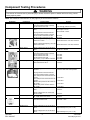
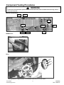
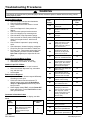
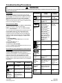
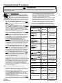
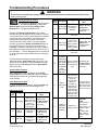
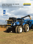
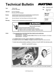
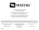
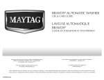
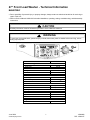
27” Front Load Washer - Technical Information
MAH8700A*
• Due to possibility of personal injury or property damage, always contact an authorized technician for servicing or
repair of this unit.
• Refer to Service Manual 16026126 for detailed installation, operating, testing, troubleshooting, and disassembly
instructions.
!
CAUTION
All safety information must be followed as provided in Service Manual 16026126.
!
WARNING
To avoid risk of electrical shock, personal injury or death; disconnect power to washer before servicing, unless
testing requires power.
Model
Power Source @ 120VAC
Amperage
Frequency
Cabinet Dimensions
Height
Width
Depth
Features
Wash Cycles
Water Temperatures
MAH8700A*
10 Amp
60 Hz
38”
27”
30.75”
26
6
Intellifill™
Water Level
Tumble Pattern
Normal
Hand Wash
Spin Speed
Max Extract Plus
Medium
Gentle
Low
Drain Only
Weight lbs.
Uncrated
June 2006
©2006 Maytag Services
35 per minute
5 per minute
1100
800
600
400
0
191
1
16026882
RPL 16026127
Component Testing Procedures
!
WARNING
To avoid risk of electrical shock, personal injury or death; disconnect power to washer before servicing, unless
testing requires power.
NOTE: See “Machine Control Board” on next page for pin and connector locations.
Illustration
Component
Thermistor
Door Switch
Water Sensor
Unplug harness connector and test
from wire insertion side of connector.
Pin #7 of CN10 and Pin #3 of CN5......
Pin #8 of CN10 and Pin #3 of CN5......
Check voltage and frequency at Pin #6
and Pin #7 of CN3...............................
Results
13K ohms @ 70F/21C (2.5V DC)
Door Open = 5V DC
Door Closed = 0V DC
60 ohms
60 ohms
Reset water level = 2.5V DC, 25.8 KHz
Check voltage and frequency at Pin #6
and Pin #8 of CN3...............................
Reset water level = 2.5V DC, 25.8 KHz
Sump Sensor
Check voltage at Pin #4 and Pin #3 of
CN8.....................................................
0V DC or 3.75V DC
Motor
Unplug harness connector and test
from wire insertion side of connector.
Pin #1 and Pin #2 of CN9....................
Pin #1 and Pin #3 of CN9....................
Pin #2 and Pin #3 of CN9....................
Any 2 Pins (1,2,3) on Motor Connector
During drain check voltage at Pin #1 of
CN5 and Pin #6 of CN10.....................
Drain Pump
Water Valves
AC Power
Heater Relay
Reactor
MEMS Sensor
16026882
RPL 16026127
Test Procedure
Unplug harness connector and test
from wire insertion side of connector.
Pin #6 and Pin #3 of CN3.....................
Check voltage at Pin #6 and Pin #4 of
CN3.....................................................
Check voltage at Pin #1 and Pin #1,2,4
of CN10...............................................
Unplug harness connector and test
from wire insertion side of connector.
(Pre valve) Pin #3 of CN10 and Pin #2
of CN7.................................................
(Hot valve) Pin #2 of CN10 and Pin #2
of CN7.................................................
(Bleach valve) Pin #4 of CN10 and Pin
#2 of CN7.....................
(Main valve) Pin #1 of CN10 and Pin
#2 of CN7............................................
Check voltage at Pin #1 and Pin #3 of
CN5.....................................................
Check voltage at Pin #1 of CN5 and
Pin #1 of CN6......................................
During water heat check voltage at Pin
#1 of CN5 and Pin #2 of RY9...............
Unplug harness connector and test
from wire insertion side........................
3.0 ohms
3.0 ohms
3.0 ohms
3.0 ohms
120V AC
120V AC when each valve operates
1100 ohms
1100 ohms
1100 ohms
1100 ohms
120V AC
120V AC
120V AC
Less than 1 ohm
Check voltage at Pin #1 and Pin #5 of
CN11...................................................
Approximately 2.5V (2.2V – 2.8V)
Check voltage at Pin #1 and Pin #4 of
CN11...................................................
Approximately 2.5V (2.2V – 2.8V)
2
June 2006
©2006 Maytag Services
Component Testing Procedures
!
WARNING
To avoid risk of electrical shock, personal injury or death; disconnect power to washer before servicing, unless
testing requires power.
Machine Control Board
CN11
CN3
1
9
1
5
CN5
3
CN8
1
5
4
1
CN10
2
2
1
1
CN6
4
8
1
3
CN7
1
CN9
RY9
MEMS Sensor
Motor
1
2
3
Normal resistance is approximately 3.0 Ω between any 2 pins (1,2 or 3) on motor
t
June 2006
3
©2006 Maytag Services
16026882
RPL 16026127
Troubleshooting Procedures
!
WARNING
To avoid risk of electrical shock, personal injury or death; disconnect power to washer before servicing, unless
testing requires power.
Will Not Start
• Plug cord into live electrical outlet. Check for
proper voltage.
• Check fuse or reset circuit breaker.
• Push any key to turn ‘ON’ the clothes washer
and press the Rotary Cycle Selector knob to
start the clothes washer.
• Close door and push the Rotary Cycle
Selector knob to start the clothes washer.
• Check to see if the clothes washer is in a pause,
soak or suds period in the cycle. Wait briefly
and it may start. If washer is in suds period,
“SudS” will display, instead of the time
remaining.
• Check for restricted drain system. If there is an
electrical problem in the drain system, “nd” error
will occur after 15 minutes.
• Check water supply.
• Check the line screen and water valve screen.
• Check for loose connections at machine control
board terminal connections CN5 and CN6 (See
“Component Testing Procedures”).
• Replace machine control board.
•
•
•
Will Not Spin
• Check to make sure the door is fully closed.
• Check for water left inside the clothes washer. If
present, see Will Not Drain.
• See Board Output Test or Quick Spin Test.
(Before test, make sure that the tumbler is
empty.) If it doesn’t tumble after the test above,
check unbalanced load scenario, machine
control board, and motor.
• Check for loose connections at pressure switch,
motor, tach harness, motor control and machine
control board terminal connections CN8, CN9,
CN3 (See “Component Testing Procedures”).
• Check motor windings resistance (See
“Component Testing Procedures”).
At CN9, pins 1 & 3 = 3.0 ohms.
Pins 1 & 2 = 3.0 ohms.
Pins 2 & 3 = 3.0 ohms.
• Check belt.
Leaking
• Make sure inlet hose connections are not
leaking. Check for rubber gasket damage due to
over-tightening.
• Check standpipe for leak. Wrap a dry rag
around the standpipe opening. If rag becomes
wet, leak is fault of home plumbing. Be sure the
standpipe is capable of accepting the incoming
flow of water from the clothes washer.
• Make sure end of drain hose is correctly
inserted and secured to drain standpipe.
• Check internal hose connections (fill, drain
systems, dispenser hoses & clamps).
• Check rubber boot. Remove, reposition and
reinstall, if necessary.
• Check for possible kinked dispenser to outer tub
hose. Hot water pressurization may force door
open.
No Tumble
• Start normal cycle with an empty machine and
allow a fill to check tumble.
• See Board Output Test, or Quick Spin Test
(Before test, make sure that the tumbler is
empty.)
• Check for loose connections at machine control
board, pressure switch, motor, tach harness and
motor control.
• Check motor windings resistance (See
16026882
RPL 16026127
“Component Testing Procedures”).
At CN9, pins 1 & 3 = 3.0 ohms.
Pins 1 & 2 = 3.0 ohms.
Pins 2 & 3 = 3.0 ohms.
Check belt.
Faulty main control board.
Faulty motor.
4
No Water Fill
• Test water fill. See Board Output Test.
• Check to make sure water supply is turned on
fully.
• Check electrical circuit and connections at the
water valve, and pressure switch.
• Check for kinks in inlet hoses.
• Check for clogged inlet screens.
• Visually check hot, cold, pre and bleach valves
separately for fill.
• Check for low water pressure. May be
dependent on pressure entering home.
Variations may occur due to usage in the home
at the time machine is used.
• Check for frozen pipes and hoses.
• Check resistance of water valve coils (See
“Component Testing Procedures”). Check pin
#2 of CN7 with pin #1, 2, 3 or 4 of CN10.
Normal is 1.18K ohms.
• Check for loose connections at the pressure
switch or on the machine control board at CN3.
(See “Component Testing Procedures”).
June 2006
©2006 Maytag Services
Troubleshooting Procedures
!
WARNING
To avoid risk of electrical shock, personal injury or death; disconnect power to washer before servicing, unless
testing requires power.
Tub Full of Suds
• Check for restricted drain system. See Will Not
Drain and Will Not Spin.
• Check for loose wire connections at control
board and pump.
• Check to see if belt is off motor and pulley.
• Use high efficiency or low sudsing detergent
specially formulated for front load washers.
• Reduce detergent amount for that specific load
size and soil level. Towel loads have a minimal
amount of soil present and typically create more
suds.
• Use drain pump and cold water to empty tub.
See Board Output Test.
• Run the clothes washer through another
complete cycle using the coldest water,
tablespoon of salt and no detergent.
Wet Clothes
• Very small clothes loads can cause unbalanced
loads. Add additional towels.
• Excessive suds may have been present, due to
not using high efficiency detergent. Reduce
amount of detergent usage.
• See Will Not Spin.
• “Drain Only” or “Low” Spin Speed was selected.
Will Not Lock
• Door not all the way closed or not properly
aligned. Possible laundry load is too large to
close door.
• Place washer into Service Mode and check for
diagnostic codes 4,18 & 22. See Service Mode.
• Check door lock system. See Board Output
Test. Check the output voltage of door lock coil.
If normal, change door lock switch. If not
normal, change main control board. (See
“Component Testing Procedures”).
• Check electrical connections at door lock switch
assembly and machine control board (CN10),
(See “Component Testing Procedures”).
Will Not Unlock
• Push door closed to make sure nothing from
inside is pressing against it, which may keep it
from unlocking.
• Door locked from water level too high. Opening
door will result in water draining from door
opening.
• Check for water remaining in the drum. If water
is present inside drum, see Will Not Drain.
• Check if temperature inside the drum is higher
than 50°C/122°F. If there is no problem with
temperature, check wiring of machine control
June 2006
5
©2006 Maytag Services
•
•
•
•
•
board and door lock switch.
Drain manually by removing drain hose clamp.
Display shows “L0”. Press Power Off button to
turn off the washer and unplug and reconnect
washer. Press any key to turn ‘ON’ the washer.
If “L0” is displayed, machine control board and
door lock switch should be checked.
Place washer into Service Mode and check for
diagnostic codes 4,18 & 22. See Service Mode.
Check electrical connections at door lock switch
assembly and machine control board (CN10).
(See “Component Testing Procedures”).
Check door lock system. See Board Output
Test. Check the output voltage of door lock coil.
If 120 V present, change door lock switch. If 120
V not present, change machine control board.
(See “Component Testing Proceduress”).
Will Not Drain
• Check for restricted drain system.
• In cold climates check for frozen drain hose.
• Check for 120 V at the pump when a spin cycle
is selected.
• Check pump motor winding resistance (See
“Component Testing Proceduress”).
Normal resistance is about 14.2 ohms (±7%).
• Check that the machine control correctly senses
the water level in the washer. See Board Input
Test.
• Check drain pump. See Board Output Test.
• Check the machine control board connections at
CN10 (Pin 6) for the pump. Should see 120 V.
(See “Component Testing Procedures”).
• Check tub to pump hose for twist in hose.
Wrong Water Temperature
• Check that both faucets are turned on fully.
• Make sure water heater is set to deliver a
minimum of 120°F (49°C) hot water at the tap.
Also check water heater capacity and recovery
rate.
• If the water heater is located a long distance
from washer, the water line may need to be
purged prior to starting wash cycle.
• Too Hot/Too Cold: This washer uses a reduced
amount of water, while the control board meters
the incoming flow to regulate the actual
temperature of the water in the tub. This may
appear to be significantly warmer/cooler than
expected.
• Make sure the temperature selection is correct.
• Disconnect inlet hoses from the Water Valve
and clean the valve screens of any debris.
16026882
RPL 16026127
Troubleshooting Procedures
!
WARNING
To avoid risk of electrical shock, personal injury or death; disconnect power to washer before servicing, unless
testing requires power.
Vibration/Walking/Noise
• Check for proper load size and distribution.
• Check for proper installation.
• Verify unit has new motion sensor / control
board.
• Check vent flappers for foam present on
flapper.
• Check for loose pump to bracket screws.
• Check for stripped pump mounting bolts.
• Check location of top suspension springs.
• Check console for broken plastic locating tabs,
check for front panel noise - add foam as
needed.
• Check if debris is present in pump causing
noise.
• Check dampers / inserts-front/grey, rear/green.
• Clean floor and check condition of rubber feet.
• Do Paper Test - Place paper strips under front
feet of washer, pull them out while in Quick
Spin Test at highest rpm. Adjust feet to hold
paper.
LED
Display
Rubber Feet Leaving Marks on Floor
• Use a pencil eraser to remove mark.
• Walk washer into location, do not drag.
Additive Cups Full of Water
• A small amount of water in cups is normal.
• Remove and wash dispenser tray, removable
cup, and rinse cap.
• Level washer.
Buttons do not Respond
• Option and Function buttons respond differently
according to each cycle.
• Child Lock feature has been selected. To
disable feature press and hold Wash/Rinse
Temp and Spin Speed simultaneously until a
beep is heard.
• When display shows “End”, only the Power Off
button will function. Press Power Off and make
new cycle selections.
Consumer Information Codes
If the consumer observes codes on display, see table
below.
Description
LED
Diagnostic
Display
nd
16026882
RPL 16026127
code
The water level fails to
drop below the Low Water
level reset within 15
minutes, before a spin
begins.
1
6
Description
Diagnostic
code
LO
Door failed to unlock after
3 attempts.
2
nF
Continuous fill of 12
minutes. Total fill of 14
minutes.
3
FL
Door failed to lock after 3
attempts.
4
LE
Water sensor level fault.
8
OE
A fault is detected in the
water level sensor. Data
(frequency) shows the
water level is at or above
the overflow level.
E
E2
A key is sensed to be
pressed more than 30
seconds, the key will be
assumed to be stuck.
15
dc
Never exceeded 400 rpm
due to an unbalanced load.
10
od
The door has not been
opened after two complete
wash cycles. Door switch
was not seen open since
the last two final spins.
17
dL
Open door lock switch with
motor running.
18
dS
Door switch is read as
open and the door locked
switch is read as locked.
22
bE
Motor tach signal exists
without motor running.
25
tE
Abnormal high/low temp or
ohm resistance seen.
29
E3
Machine control is
attempting to drive the
motor but is not seeing any
tach response. Visual
check shows motor is not
moving. (Locked, Hall
Sensor fault).
2E
Sr
System Relay failure.
34
Hr
Heater Relay failure
36
3E
Over Current is detected.
Motor won't turn.
3E
2E
Voltage for motor control
bus is over specified limit.
91
2E
Voltage for motor control
bus is under specified limit.
92
June 2006
©2006 Maytag Services
Troubleshooting Procedures
!
WARNING
To avoid risk of electrical shock, personal injury or death; disconnect power to washer before servicing, unless
testing requires power.
Service Mode
Test or Display
Service Mode enables service personnel to verify the
operation of the washing machine and diagnose problems.
Service Mode can be entered in the middle of any wash
cycle without interrupting the cycle. While in Service
Mode, the technician can cancel the current cycle, set a
continuous running mode, start a variety of special service
tests and view diagnostic displays.
Press Power Off
(also exits
Service Mode)
Press Rinse & Spin
and Spin Only
together
Press Rinse &
Spin and Spin
Only
Press Delay for 3
seconds (then
individual buttons to
test) Turn Rotary
Cycle Selector
clockwise, the LED’s
around it will be
toggled. Turn Rotary
Cycle Selector
counterclockwise, the
7-segment LED’s
toggle. Press Rotary
Cycle Selector, all of
the LED’s around the
Rotary Cycle
Selector will be
toggled.
Press Power Off
twice after
starting test
Press Spin Only
Press Spin Only
Press Spin Speed
Press Power
Off.
Press Rinse & Spin –
displays ‘d’
Press Rinse &
Spin again
All Diagnostic
Codes
Rotate Rotary Cycle
Selector either
direction
N/A
Cycle Count
No. for
Diagnostic
Code
Press and hold Rotary
Cycle Selector, while
diagnostic code is
displayed
Release Rotary
Cycle Selector
(returns to
diagnostic code
display)
Clear All
Diagnostic
Codes
Press Delay and
Chime together while
displaying diagnostic
codes
N/A
Display
Software
Version
Press Soil Level.
Press Soil
Level.
Cycle Count
Press Chime
N/A
Quick
Service
Cycle
Hold Quick
Service Cycle
Step
Enter / Exit Service Mode
LED/Switch
Test
IN
Test or Display
To Start
(or Hold)
Press Delay and
Rinse & Spin or
press Power Off
Hold Quick
Spin Test
step
Press Rotary Cycle
Selector (during test)
Press Rotary
Cycle Selector
Fast
TimeDown
Test / Advance
to next step
Press Wash/Rinse
Temp to start test.
Press Wash/Rinse
Temp during cycle to
advance.
Press Power Off
June 2006
©2006 Maytag Services
Diagnostic
Code Display
(Initial)
To Cancel
(or resume)
Press Delay and
Rinse & Spin
Quick
Spin Test
Board
Input
Test
Board
Output
Test /
System Check
Access Service Tests and Diagnostic Features while in
Service Mode.
The following table summarizes special tests and features
available in Service Mode, along with methods of
activation and cancellation. A more detailed description of
each test can be found in the text following the table.
Reference the text or symbol indicated in the “Test or
Display” column, with the text and symbols indicated in the
text following the quick reference table for a more detailed
explanation.
To Cancel
(or resume)
Press Wash/Rinse
Temp and Soil Level
#
To enter Service Mode press the Chime and Extra Rinse
keys for 3 seconds or until the control beeps.
NOTE: The washer must be ‘ON’ before Service Mode
can be entered.
The motor speed will be displayed when started (motor not
running display will be “0”). The present state of the
machine will not be changed (i.e., the current cycle in
progress will not be interrupted and only the display will
change). All LED’s will be turned ‘OFF’ except the Door
Lock LED; it will continue to display the condition of the
door lock.
To exit Service Mode:
1) Press Chime and Extra Rinse keys for 3 seconds
again, or
2) Press Power Off button, or
3) Unplug the machine.
To pause while in Service Mode:
Pressing the Rotary Cycle Selector knob while running a
test will pause the individual test.
To Start
(or Hold)
7
16026882
RPL 16026127
Troubleshooting Procedures
!
WARNING
To avoid risk of electrical shock, personal injury or death; disconnect power to washer before servicing, unless
testing requires power.
Quick Spin Test
While in Service Mode, press Delay and Rinse &
Spin keys to start a Quick
Spin Test. Quick Spin Test steps follow:
•
Start spinning, and after reaching a maximum spin
speed.
•
Stay at maximum spin speed for 2 minutes and stop
Quick Spin Test.
6.
7.
The “SC” in the display will blink as an indication of failure,
and continue blinking until the Quick Service Cycle test has
reached the end. Any diagnostic code logged during this test
will result in failure of the test, but will not necessarily stop the
test. During the Quick Service Cycle, pressing the Spin
Speed key will advance to the next step. Pressing the Rinse
& Spin and Spin Only keys will suspend the machine at the
current step for up to 10 minutes or until Delay and Chime
keys are pressed. All LED’s should flash ‘ON’ and ‘OFF’ while
the system is suspended or on hold.
Hold Quick Spin Step
If the Rotary Cycle Selector knob is pressed
during the Quick Spin Test, the machine will hold
at the next highest index speed for 10 minutes (1 minute on
early MAH8700’s). At the end of ‘Hold’ time, the machine will
resume and finish the Quick Spin Test. To cancel the ‘Hold’
and allow the Quick Spin Test to continue, press the Delay
and Rinse & Spin keys.
¤
Fast Time Down Test
LED/Switch Test
While any test or cycle is running in Service
Mode, pressing the
Wash/Rinse Temp key will advance the program to the
next cycle stage. Cycle stages are located at key
locations in the machine operation. As the program is
advanced it will index as follows: The end of each fill (the
same as the beginning of a tumble session for Wash, or
Rinse); at the beginning of a drain session; at the
beginning of a spin session (at this position, check the
water level, if over reset level, drain first before entering
the spin function); at the beginning of a fill session; at the
beginning of Bleach fill; at the beginning of Fabric
Softener fill; and every 3 minutes during the tumble
sessions (Wash and Rinses).
#
the washer to next step if water is not connected to
machine.
Drain and spin to maximum speed. Machine will achieve
maximum speed using the safest, fastest method.
Display a “PA” (Passed) continuously for 5 seconds if no
diagnostic codes were logged during the test. Washer will
return to the normal Service Mode at the end of the 10
second period.
While in Service Mode, press the Delay key
to start a LED/Switch Test. All the LED’s can be toggled or
slewed by pressing the key associated with the LED or set of
LED’s. All keys (including the Power Off button) must be
pressed within 5 minutes for this test to pass. “PA” will be
displayed for five (5) seconds once all keys have been
pressed and the test is completed. Following 20 seconds of
inactivity at any point, this test will exit without any display.
The Power Off button must be pressed twice within 30
seconds to cancel this test.
Switch
Delay
Chime
Extra Rinse
Soil Level
Spin Speed
Wash/Rinse
Temp
Rinse & Spin
Spin Only
Prewash
Extended Spin
Rotary Cycle
Selector
Rotary Cycle
Selector
Rotary Cycle
Selector
Power Off
Quick Service Cycle
While in Service Mode, pressing the
Wash/Rinse Temp and Soil Level keys for
3 seconds will start a Quick Service Cycle. This will be a
quick check of all systems. If display shows “od” then open
and close door. Pressing Spin Speed key will advance to the
next cycle. The following steps are performed: Display shows
“SC”.
1. Hot water for 5 seconds and then turn off.
2. Cold water for 5 seconds and then turn off.
3. Bleach valve for 5 seconds and then turn off.
4. Softener dispenser using cold water and bleach water for
5 seconds and then turn off.
5. Turn ‘ON’ Cold valves until the control detects proper
water level. During this time, tumble at 45 rpm for 5
seconds in a clockwise direction, pause for 2 seconds,
tumble at 45 rpm for 5 seconds in a counterclockwise
direction, pause for 2 seconds. Continue pattern until the
water level is detected.
Minimum time for this segment to be 5 seconds. After
water height is achieved, continue tumble pattern for
another 14 seconds. If the washer is equipped, turn ‘ON’
heater for first 5 seconds of this tumble pattern. Advance
16026882
RPL 16026127
8
Action
Press once
Press 3 times
Press once
Press 3 times
Press 6 times
Press 6 times
Press once
Press once
Press once
Press once
Rotate 1 full revolution clockwise
1 position counterclockwise
Press once
Press once
June 2006
©2006 Maytag Services
Troubleshooting Procedures
!
WARNING
To avoid risk of electrical shock, personal injury or death; disconnect power to washer before servicing, unless
testing requires power.
Board Input Test
While in Service Mode, pressing the
IN
Spin Only key will begin the Board Input
Test. This test turns on a specified output
after a key press. Pressing the Spin Only key again
cancels the test. (Display shows “in”).
While in Service Mode follow chart to check respective
function.
• When the Rotary Cycle Selector knob is set to
“Super Wash” and the Rotary Cycle Selector knob
is pressed, the door position will be displayed: “0P” if
open, “CL” if closed.
• When the Rotary Cycle Selector knob is set to
“Normal” and the Rotary Cycle Selector knob is
pressed, the Lock position will be displayed: “UL” if
unlocked, “L0” if locked.
• When the Rotary Cycle Selector knob is set to
“Whites” and the Rotary Cycle Selector knob is
–
pressed, the High water level will be displayed: “ 0”
–
if below level, “ 1” if above level. The High water
level is defined as the over flow water level.
• When the Rotary Cycle Selector knob is set to
“Wrinkle Control” and the Rotary Cycle Selector
knob is pressed, the Medium water level will be
displayed: “—0” if below level, “—1” if above level.
The Medium water level is defined as the minimum
water level needed such that the heater can be
turned ‘ON’ (only MAH8700* and MAH9700* models
have heaters).
• When the Rotary Cycle Selector knob is set to
“Colors” and the Rotary Cycle Selector knob is
pressed, the Low water level will be displayed: “_0” if
below level, “_1” if above level. The Low water level
is defined as the reset water level.
• When the Rotary Cycle Selector knob is set to
“Hand Wash” and the Rotary Cycle Selector knob
is pressed, the level of Tub unbalance will be
displayed: “UC” if balanced, “U0” if unbalanced. “U0”
will be displayed during the time when the machine
is correcting for the unbalance; e.g. slowing down to
redistribute the load or to get to a lower spin speed.
Once the situation has been corrected (i.e. the load
has begun tumbling or the lower speed has resulted
in an acceptable amount of balance); “UC” will once
again be displayed.
• When the Delay key is pressed, the water
temperature will be displayed in Degrees F
(Fahrenheit).
• When the Rotary Cycle Selector knob is set to
“Delicates” and the Rotary Cycle Selector knob is
pressed, the water temperature will be displayed in
degrees C (Celsius).
June 2006
©2006 Maytag Services
9
•
When the Rotary Cycle Selector knob is set to
“Super Wash”, the LED lights up. Revolve Rotary
Cycle Selector knob clockwise until all LED’s are
‘OFF’, then press Rotary Cycle Selector knob to
display frequency reading. “2560” means 25.60 Hz
(washer empty).Frequency value drops as water
rises.
While performing the Board Input Test in Service
Mode, follow this quick reference chart to check
respective functions.
Selection
Function
Display
Rotary Cycle
Selector set to
“Super Wash”.
Door position
“0P” or “CL”
Press Rotary Cycle
Selector.
Rotary Cycle
Selector set to
“Normal”. Press
Lock state
“UL” or “L0”
Rotary Cycle
Selector.
Rotary Cycle
–
“ 0” if below
Selector set to
High water
–
“Whites”. Press
level. “ 1” if
level
Rotary Cycle
above level.
Selector.
Rotary Cycle
Selector set to
“—0” if below
Medium water
“Wrinkle Control”.
level. “—1” if
level
Press Rotary Cycle
above level.
Selector.
Rotary Cycle
“_0” if below
Selector set to
“Colors”. Press
Low water level
level. “_1” if
Rotary Cycle
above level.
Selector.
Rotary Cycle
“UC” if
Selector set to
“Hand Wash”.
Tub balance
Balanced. “U0”
Press Rotary Cycle
if Unbalanced
Selector.
Water
Degrees F
Press Delay key.
temperature
Rotary Cycle
Selector set to
Water
Degrees C
“Delicates”. Press
temperature
Rotary Cycle
Selector.
“2560” (empty).
All cycle LEDs are
Water Level
Frequency
off, press Rotary
Frequency(Hz) drops as water
Cycle Selector
rises.
16026882
RPL 16026127
Troubleshooting Procedures
!
WARNING
To avoid risk of electrical shock, personal injury or death; disconnect power to washer before servicing, unless
testing requires power.
Board Output Test
While in Service Mode, pressing the Spin
Speed key will begin the Board Output Test.
This test turns ‘ON’ a specified output after a
key press. Pressing the Spin Speed key again
cancels the test. Only one output can be ‘ON’ at any time. All
outputs will be turned ‘OFF’ after five (5) minutes of inactivity.
•
When the Rotary Cycle Selector knob is set to “Super
Wash” and the Rotary Cycle Selector knob is pressed,
the main relay will be toggled (either from ‘ON’ to ‘OFF’ or
from ‘OFF’ to ‘ON’).
•
When the Rotary Cycle Selector knob is set to “Normal”
and the Rotary Cycle Selector knob is pressed, the hot
water valve will be turned ‘ON’. This output will remain
‘ON’ until the Rotary Cycle Selector knob is pressed
again to turn ‘OFF’ the output. The control will not allow
the machine to fill past the High water level.
•
When the Rotary Cycle Selector knob is set to “Wrinkle
Control” and the Rotary Cycle Selector knob is pressed,
the cold water valve will be turned ‘ON’. This output will
remain ‘ON’ until the Rotary Cycle Selector knob is
pressed again to turn ‘OFF’ the output. The control will
not allow the machine to fill past the High water level.
•
When the Rotary Cycle Selector knob is set to
“Delicates” and the Rotary Cycle Selector knob is
pressed, the bleach valve will be turned ‘ON’. This output
will remain ‘ON’ until the Rotary Cycle Selector knob is
pressed again to turn ‘OFF’ the output. The control will
not allow the machine to fill past the High water level.
•
When the Rotary Cycle Selector knob is set to “Hand
Wash” and the Rotary Cycle Selector knob is pressed,
the pre wash valve will be turned ‘ON'. This output will
remain ‘ON’ until the Rotary Cycle Selector knob is
pressed again to turn ‘OFF’ the output. The control will
not allow the machine to fill past the High water level.
•
When the Rotary Cycle Selector knob is set to “Quick
Wash” and the Rotary Cycle Selector is pressed, the
drain pump will be turned ‘ON’. This output will remain
‘ON’ until the Rotary Cycle Selector knob is pressed
again to turn ‘OFF’ the output.
•
Pressing the Delay key will turn ‘ON’ the motor and the
Delay LED. This output and the LED will remain ‘ON’ until
the Delay key is pressed again to turn ‘OFF’ the output.
When activated, the machine will tumble for 5 seconds in
the CW direction, pause for 2 seconds, tumble in the
CCW direction for 5 seconds, pause for 2 seconds;
repeating this pattern until Delay key is pressed again to
turn ‘OFF’ the tumbling.
Note: All tumble speeds are assumed to be 45 rpm.
•
•
•
Pressing the Chime key will unlock the door and turn
‘ON’ all the LED’s above the Chime key. This output will
attempt to unlock one time, if safe to do so.
Pressing the Wash / Rinse Temp key will lock the door
and all the Wash / Rinse Temp LED’s will turn ‘ON’.
Pressing the Chime key will unlock the door and the all
the Chime LED’s will turn ‘ON’.
When the Rotary Cycle Selector knob is set to “Whites”
and the Rotary Cycle Selector knob is pressed, the
bleach valve and the cold water valve will be turned ‘ON'
16026882
RPL 16026127
to check the fabric softener fill. This output will remain
‘ON’ until the Rotary Cycle Selector knob is pressed
again to turn ‘OFF’ the output. The control will not allow
the machine to fill past the High water level.
•
Pressing the Rinse & Spin key will turn ‘ON’ the heater if
the water level is above the Heater Safety Level. If the
water level is below the Heater Safety Level, a warning
beep will be given and the heater will not be turned ‘ON’.
The heater output will remain ‘ON’ until the “Rinse &
Spin” key is pressed again to turn ‘OFF’ the output.
While performing the Board Output Test in Service Mode,
follow this quick reference chart to check respective function.
Selection
Rotary Cycle
Selector set to “Super
Wash”. Press Rotary
Cycle Selector.
Rotary Cycle
Selector set to
“Normal”. Press
Rotary Cycle
Selector.
Rotary Cycle
Selector set to
“Wrinkle Control”.
Press Rotary Cycle
Selector.
Rotary Cycle
Selector set to
“Delicates”. Press
Rotary Cycle
Selector.
Rotary Cycle
Selector set to “Hand
Wash”. Press Rotary
Cycle Selector.
Rotary Cycle
Selector set to “Quick
Wash”. Press Rotary
Cycle Selector.
Function
Main Relay
‘ON’ to ‘OFF’ or
‘OFF’ to ‘ON’.
Hot Water
Valve
1st press valve
‘ON’. 2nd press
valve ‘OFF’.
Cold Water
Valve
1st press valve
‘ON’. 2nd press
valve ‘OFF’.
Bleach Valve
1st press valve
‘ON’. 2nd press
valve ‘OFF’.
Pre Wash
Valve
1st press, valve
‘ON’. 2nd press,
valve ‘OFF’.
Motor
Press Chime
Door Lock
Press Wash / Rinse
Temp
Rotary Cycle
Selector set to
“Whites”. Press
Rotary Cycle
Selector.
1st press Drain
Pump ‘ON’. 2nd
press Drain
Pump ‘OFF’.
1st press Motor
on. 2nd press
Motor ‘OFF’.
1 Attempt to
unlock.
Drain Pump
Press Delay
Press Rinse & Spin
10
Component
Door Lock
Lock Door
Bleach Valve
and Cold
Water Valve
1st press, Fabric
Softener Fill. 2nd
press, valves
‘OFF’
Heater
1st press, heater
‘ON’ if water level
high enough. 2nd
press, heater
‘OFF’.
June 2006
©2006 Maytag Services
Troubleshooting Procedures
!
WARNING
To avoid risk of electrical shock, personal injury or death; disconnect power to washer before servicing, unless
testing requires power.
Display Diagnostic Codes
The diagnostic code display can be toggled
‘ON’ and ‘OFF’ from Service Mode by pressing the
Rinse & Spin key and rotating the Rotary Cycle
Selector knob. The display will show a “d”.
Diag. Description
Code
4
Rotating the Rotary Cycle Selector knob in either
direction will cycle through the list of codes one code at
a time with no wrap. Once an initial direction is selected
by the user (either Clockwise or Counterclockwise),
subsequent movements of the knob in the same
direction will show older codes. If the user changes
direction and turns the Rotary Cycle Selector knob in
the opposite direction, the more recent code will be
displayed. If rotation is continued to the limits of the list,
the display will remain at the top or the end of the list. A
pair of dashes “- -” will be displayed at the end of the list
of codes, when the control reaches the top, it will again
show “d”.
5-7
8
1
2
No Drain
The door
fails to
unlock
3
No Fill
June 2006
©2006 Maytag Services
The water level
fails to drop
below the Low
Water level reset
within 15
minutes, before
a spin begins.
Door failed to
unlock after 3
attempts
Continuous fill of
12 minutes.
Total fill of 14
minutes.
Input signal from
water level
sensor is out of
Water level
range, Washer
sensor fault. will beep and
pause the wash
cycle.
Not Used
E
Water level in
the machine is
believed to be
above the
overflow level.
When this
Water
condition is
sensor level detected, the
fault.
machine will
automatically
begin pumping
water out until it
falls below the
overflow level.
First check to see
that water valve is
not stuck. If water
valve is OK, check
water level sensor.
Displays "nd".
See Will Not Drain
“Troubleshooting
Procedures”.
11
Displays "LO". See
Will Not Unlock
“Troubleshooting
Procedures”.
12-14
11
Displays "LE". See
No Water Fill
“Troubleshooting
Procedures”.
10
Action to be
taken
Displays "nF".
See No Water Fill
“Troubleshooting
Procedures”.
Displays "FL".See
Will Not Lock
“Troubleshooting
Procedures”.
Will display “dc”
See Wet Clothes
"Troubleshooting
Procedures".
Diagnostic Codes
Trigger
Door failed to
lock after 3
attempts
Unbalance
or cabinet
hit detected
during final Never exceeded
spin, which 400 rpm due to
prevented an unbalanced
load.
the spinner
from
exceeding
400 rpm
Access Other Features
While a diagnostic code is displayed, if the Rotary
Cycle Selector knob is pressed and held, the machine
will display the number of cycles since the diagnostic
code occurred.
Clear Diagnostic Codes
To clear the diagnostic codes list, press the Delay and
Chime keys for 3 seconds while viewing the list.
Action to be
taken
Not Used
9
A code generated during the current cycle will be
displayed with the Spin Speed LED turned ‘ON’. If no
cycle is currently running, a code generated during the
previous cycle will be displayed with the Spin Speed
LED turned ‘ON’.
Diag. Description
Code
The door/lid
fails to lock
Trigger
Will not
remember
machine
settings
See Clear
Diagnostic
Codes.
Disconnect and
reconnect the
Difficulty in
washer power cord
reading memory at power supply
outlet.
If condition still
exists, replace
machine control
board.
Not Used
16026882
RPL 16026127
Troubleshooting Procedures
!
WARNING
To avoid risk of electrical shock, personal injury or death; disconnect power to washer before servicing, unless
testing requires power.
Diag. Description
Code
15
Trigger
A key is sensed
to be pressed
more than 30
Stuck Key seconds, the key
will be assumed
to be stuck.
Action to be
taken
Diag. Description
Code
Display "E2". See
LED/Switch Test.
Check connection
of keypad to
control board.
Replace console if
necessary.
17
Will display "od". If
door open sensed,
error will clear.
Check door lock.
18
19-21
22
34
Machine control
Display "Sr".
does not see
System
Replace machine
Relay failure relay open when
control board.
it should.
35
Not Used
3E
Displays
"3E".Check the
Motor failure Over Current is
motor windings,
detected. Motor
(Over
the speed sensor,
won't turn.
current)
wiring connections,
or Control Board.
Door/lid
Door switch is
switch
read as open
detected
and the door
open during
locked switch is
cycle (when
read as locked.
not paused).
91
92
Not Used
Voltage for
Voltage for motor
motor control
control bus is
bus is over
over limit
specified limit
Voltage for motor
Voltage for
control bus is
motor control
under specified
specified limit
limit.
Display
"2E".Replace
Machine Control
Board.
Display
"2E".Replace
Machine Control
Board.
Exit Service Mode
To exit:
1) Press Chime and Extra Rinse keys for 3
seconds again, or
2) Press the Power Off key, or
3) Unplug the machine. After five (5) minutes of
inactivity (user key presses) in Service Mode,
the machine will exit the Service Mode and
resume normal operations. Pressing the Power
Off key will completely exit Service Mode. If a
cycle is running, cancel the cycle. Pressing the
Rotary Selector knob while running a test will
pause the individual test, while remaining in
Service Mode. A power loss during Service
Mode will cancel this mode.
See Door Lock
Test
“Troubleshooting
Procedures”.
Not Used
Tach signal
Motor tach
exists without Displays "bE".
signal exists
torque command Replace Motor
without motor
or when not
Control Board.
running.
expected.
26-28
29
40-49
Not Used
23-24
25
Display “E3”
Evaluate wire
harness for loose
or unhooked
connections. If
machine has
separate motor
control, perform
self diagnostic
motor test. See
“Board Output
Test”.
2E
spins.
Check for loose
wire connections.
Clear the
diagnostic code
and recheck; if
reoccurs, see
Detected
Door Lock Test.
door lock
Check door lock
switch open Open door lock system. See
switch with
during cycle motor running. Board Output
Test. Check the
when not
output voltage of
expected.
door lock coil. If
normal, change
door lock switch. If
not normal, change
Machine Control
Board.
Action to be
taken
Machine control
is attempting to
drive the motor
Motor Drive
but is not seeing
failure
any tach
(Locked, Hall
response. Visual
sensor fault)
check shows
motor is not
moving.
The door has not
been opened
Door/Lid
after two
switch was
complete wash
not seen
cycles. Door
open since switch was not
the last two seen open since
final spins the last two final
Trigger
Not Used
Sump
thermistor
failure
(Optional)
30-33
16026882
RPL 16026127
Displays " tE".
Abnormal
- Loose or pinched
high/low temp or
wires.
ohm resistance
- Bad sump
seen
thermistor.
Not Used
12
June 2006
©2006 Maytag Services
Wiring Schematics
!
WARNING
To avoid risk of electrical shock, personal injury or death; disconnect power to washer before servicing, unless
testing requires power.
NOTE: Series 10 – 11 do not have connector CN11 or MEMS PCB originally.
Series 12
June 2006
©2006 Maytag Services
13
16026882
RPL 16026127