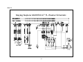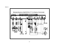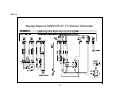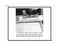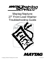
1
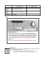
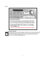
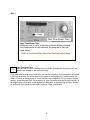
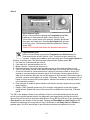
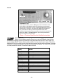
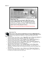
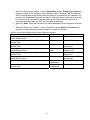
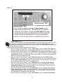
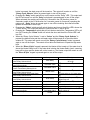
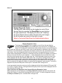
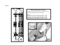
Maytag Neptune
27” Front Load Washer
Troubleshooting Guide
© Maytag Technical Training Services 2005
L2005-005
Slide 1 – Troubleshooting
Slide 2
Always refer to the Technical Data Sheet shipped with the product for detailed information
for the model you are servicing. Follow all Caution and Safety Warnings
The following is an example of the information available on the Technical Data Sheet
Will Not Start
• Plug cord into live electrical outlet. Check for proper voltage.
• Check fuse or reset circuit breaker.
• Push any key to turn on the clothes washer. Push the rotary selector knob to start the washer.
• Close door and push the rotary selector knob to start the clothes washer.
• Check to see if the washer is in a pause or soak period in the cycle. Wait briefly for machine
to start. (If washer is in suds period, “SUDs” will display instead of remaining time.
• Check for restricted drain system. During an electrical drain problem, “nd” error will occur
after 15 minutes.
• Check water supply is working.
• Check water valve connections are good.
• Check the line filter and water valve filter.
• Check the machine control board terminal connections CN5, CN6 for good connections.
• Replace console control board.
Leaking
• Make sure inlet hose connections are not leaking. Check for rubber gasket damage due to
over-tightening.
• Check standpipe for leak. Wrap a dry rag around the standpipe opening. If rag becomes wet,
leak is fault of home plumbing. Be sure the standpipe is capable of accepting the flow of
water from the washer.
• Make sure end of drain hose is correctly inserted and secured to drain standpipe.
• Check internal hose connections (fill, drain systems, dispenser hoses & clamps).
• Check rubber boot. Remove, reposition and reinstall, if necessary.
• Check for possible kinked dispenser to outer tub hose. Hot water pressurization may force
door open.
No Tumble
• Start normal cycle with an empty machine and allow a fill to check tumble.
• Perform Board Output Test, or Quick Spin Test (Before test, make sure that the tumbler is
empty.)
• Check for loose connections at Machine Control Board, Pressure Switch, Motor, Tach
Harness and Motor Control. (Refer to the component testing procedure)
• Check motor windings resistance. (CN9 pins 1 &3 = 11.6ohms(±7% 20°C/68°F basis), pins 1
& 2 = 11.6ohms(±7%20°C/68°F basis), Pin2 & 3 = 11.6 ohms (±7% 20°C/68°Fbasis)
• Check belt.
• Faulty Main Control Board.
• Faulty motor.
1
Will Not Spin
• Check to make sure the door is fully closed.
• Check for water left inside the washer. If present, see Will Not Drain.
• Perform Board Output Test or Quick Spin Test. (Before test, make sure that the tumbler is
empty.) If it doesn’t tumble after the test above, check unbalanced load scenario, Main
Control Board, and motor.
• Check for loose connections at Machine Control Board, Pressure Switch, Motor, Tach
Harness and Motor Control. (CN8, CN9, CN3) Refer to the component testing procedure.
• Check motor winding resistance (CN9 pins 1&3=11.6ohms ±7%@68F, pins 1&2=11.6ohms
±7%@68F, pins 2&3=11.6ohms. ±7%@68F.
Tub Full of Suds
• Check for restricted drain system. See Will Not Drain and Will Not Spin.
• Check for loose wire connections at Control Board and pump.
• Perform Board Output Test.
• Use high efficiency or low sudsing detergent specially formulated for front load washers.
• Reduce detergent amount for that specific load size and soil level. Towel loads have a
minimal amount of soil present and typically create more suds.
• Run the clothes washer through another complete cycle using the coldest water, tablespoon
of salt and no detergent.
Wet Clothes
• Very small clothes loads can cause unbalanced loads. Add additional towels.
• Excessive suds may have been present, due to not using High-Efficiency detergent. Reduce
amount of detergent usage.
• See Will Not Spin.
• Low Spin Speed or Drain Only was selected.
Will Not Drain
• Check for restricted drain system.
• In cold climates check for frozen drain hose.
• Check for 120 VAC at the pump when a spin cycle is selected.
• Check pump motor winding resistance. (14.2 ±7% ohms)
• Check that the machine control correctly senses the water level in the washer. See Board
Input Test.
• Go to Board Output Test and perform Pump Out Test.
• Check the Machine Control Board connections at CN10 (Pin 6) for the pump. Should see
110-120VAC.(Refer to the component testing procedure).
• Check tub to pump hose for twist in hose.
Wrong Water Temperature
• Check that both faucets are turned on fully.
• Make sure water heater is set to deliver a minimum of 120°F (49°C) hot water at the tap. Also
check water heater capacity and recovery rate.
• If the water heater is located a long distance from washer, the water line may need to be
purged prior to starting wash cycle.
• Too Hot/Too Cold: This washer uses a reduced amount of water, while the control board
meters the incoming flow to regulate the actual temperature of the water in the tub. This may
appear to be significantly warmer/cooler than expected.
• Make sure the temperature selection is correct.
• Disconnect inlet hoses from the Water Valve and clean the valve screens of any debris.
2
Noisy and/or Vibration/Walking
• Check if the washer was properly leveled and the locking nuts are securely tightened up
against the base frame of the washer.
• Check and determine all four of the shipping bolts and spacers have been fully removed from
the rear panel of the washer.
• Check for proper load size and distribution. If clothes load is too small, add a few towels to
balance the clothes load better.
• Check the tightness of the rear pulley bolt. Tighten if necessary.
• Clean floor and bottom side of washer feet. Check clearance. Refer to the back of machine
and Installation Instruction.
Rubber Feet Leaving Marks on Floor
• Use a pencil eraser to remove mark.
• Walk washer into location, do not drag.
Additive Cups Full of Water
• Small amount of water in bottom of additive cups is normal.
• Remove and wash Dispenser Tray, removable Cup, and Rinse Cap.
• Level washer.
•
Buttons do not Respond
• Option and Function buttons respond differently according to each cycle.
• Child Lock feature has been selected. To disable feature press and hold Wash/Rinse Temp
and Spin Speed simultaneously until a beep is heard.
• When display shows "End", only the Power Off button will function. Press Power Off and
make new cycle selections.
Consumer Information Codes
If the consumer observes codes on display, see table below.
LED
Display
nd
Description
The water level fails to drop below the Low Water level
reset within 15 minutes, before a spin begins.
Door failed to unlock after 3 attempts.
LO
Continuous fill of 12minutes. Total fill of 14minutes.
nF
Diagnostic code
1
2
3
FL
Door failed to lock after3 attempts.
4
LE
Water sensor level fault.
8
OE
A fault is detected in the water level sensor. Data
(frequency) shows the water level is at or above the
overflow level.
E
3
LED
Display
Description
Diagnostic code
E2
Detected a key pressed more than 30seconds, the key
will be assumed to be stuck.
15
dc
Never exceeded 400rpm due to an unbalanced load.
10
od
The door has not been opened after two complete wash
cycles. Door switch was not seen open since the last two
final spins.
17
dL
Open door lock switch with motor running.
18
dS
Door switch is read as open and the door locked switch
is read as locked.
22
bE
Motor tach signal exists without motor running.
25
tE
Abnormal high/low temp or ohm resistance seen.
29
E3
Machine control is attempting to drive the motor but is
not seeing any tach response. Visual check shows motor
is not moving. (Locked, Hall Sensor fault)
2E
Sr
System Relay failure.
34
Hr
Heater Relay failure.
36
3E
Over Current is detected. Motor won't turn.
3E
2E
Voltage for motor control bus is over specified limit.
91
2E
Voltage for motor control bus is under specified limit.
92
Slide 3
Service Mode
Service Mode enables service personnel to verify the operation of the washing machine and
diagnose problems. Service Mode can be entered in the middleof any wash cycle without
interrupting the cycle. While in Service Mode, the technician can cancel the current cycle,
set a continuous running mode, start a variety of special service tests and view diagnostic
displays
4
Slide 4
Press and
hold 3 Sec.
Service Mode
Enter / Exit Service Mode
To enter Service Mode press the Chime and Extra Rinse
keys for three seconds or until the control beeps.
NOTE: The washer must be on before the Service Mode
can be entered.
Refer to Technical Data Sheet for Detailed Instructions
The motor speed will be displayed when started (motor not running display will be 0). The present
state of the machine will not be changed (i.e., the current cycle in progress will not be interrupted
and only the display will change). All LED’s will be turned off except the “Door Lock” LED. It will
continue to display the condition of the door lock.
To exit:
1) Press Chime and Extra Rinse keys for 3 seconds again, or
2) press Off, or
3) unplug the machine. Pressing the Rotary Selector knob while running a test will pause the
individual test, while remaining in Service Mode.
The following table summarizes special tests and features available in Service Mode, along with
methods of activation and cancellation.
Access Service Tests and Diagnostic Features while in Service Mode.
Test or Display
Press LED to Start
Press LED to Cancel
Quick Spin
Test
Press Delay Start and Rinse&Spin
5
Press Delay start and Rinse&Spin
Press Off (exits Service Mode)
Test or Display
Press LED to Start
Hold Quick
Spin Step
(holds
predefined
RPM)
Fast
TimeDown /
Advance to
Next Step
Quick
Service
Cycle
Hold Quick
Service Cycle
Step
#
LED/Switch
Test
Board
Input
Test
Board
Output
Test /
System Check
IN
Diagnostic
Code Display
(Initial)
All Diagnostic
Codes
Cycle Count
No. for
Diagnostic
Code
Press LED to Cancel
Press Rotary Selector (during test)
Press Rotary Selector (cancels
hold & resumes next step)
Press Temperature to start test. Press
Temperature during cycle to advance.
Press Power Off
Press Temperature and Soil Level
Press Off (also exits Service Mode)
Press Rinse&Spin and Spin Only
together
Press Rinse&Spin and Spin Only
to resume
Press Delay for 3 seconds (then
individual buttons to test) Rotate Cycle
Selector clockwise, the LED’s around it
will be toggled. Rotate
counterclockwise, the7-segment LED’s
toggle. Press Rotary Cycle Selector, all
of the LED’s around the Rotary Cycle
Selector will be toggled.
Press Spin Only
Press Off twice after starting test
Press Spin Speed
Press Off
Press Rinse& Spin – displays “d”
Press Rinse&Spin again
Rotate Cycle Selector either direction
N/A
Press and hold Rotary Selector, while
diagnostic code is displayed
Release Rotary Selector (returns
to diagnostic code display)
6
Press Spin Only
Test or Display
Press LED to Start
Clear All
Diagnostic
Codes
Display
Software
Version
Cycle Count
Press LED to Cancel
Press Delay and Chime together while
displaying diagnostic codes
Press Soil Level. Press 2 times for
displays with only 2 character positions.
Press Soil Level a 3rd time
Press Chime
Slide 5
Press
Quick Spin Test
Quick Spin Test
While in Service Mode, press Delay and Rinse&Spin key to
start a Quick Spin Test. Quick Spin test steps are as follows:
• Start spinning and after reaching a maximum spin speed,
stay at maximum spin speed for 2 minutes and stop Quick
Spin Test
Refer to Technical Data Sheet for Detailed Instructions
Quick Spin Test
While in Service Mode, press Delay and Rinse&Spin keys to start a Quick Spin Test.
Quick Spin test steps are as follows:
• Start spinning and after reaching a maximum spin speed.
• stay at maximum spin speed for 2 minutes and stop Quick Spin Test.
7
Slide6
Press
Hold Quick Spin Test
Hold Quick Spin Step
If the Rotary Selector key is pressed during the Quick Spin
test, the machine will hold at the next highest index speed
for up to 10 minutes. At the end of 10 minutes, the machine
will resume and finish the Quick Spin test. To cancel the
Hold and allow the Spin Test to continue, press the Delay
and Rinse&Spin keys.
Refer to Technical Data Sheet for Detailed Instructions
Hold Quick Spin Step
If the Rotary Selector key is pressed during the Quick Spin test, the machine will hold at the
next highest index speed for up to 10 minutes. At the end of 10 minutes, the machine will
resume and finish the Quick Spin test. To cancel the Hold and allow the Spin Test to
continue, press the Delay and Rinse&Spin keys.
8
Slide 7
Press
Fast Time Down Test
Fast Time Down Test
While any test or cycle is running in Service Mode, pressing
the Temperature key will advance the program to the next
cycle stage.
Refer to Technical Data Sheet for Detailed Instructions
¤
Fast Time Down Test
While any test or cycle is running in Service Mode, pressing the Temperature key will
advance the program to the next cycle stage.
Cycle stages are located at key locations in the machine operation. As the program is advanced
it will index as follows: The end of each fill (the same as the beginning of a tumble session for
Wash, or Rinse); at the beginning of a drain session; at the beginning of a spin session (at this
position, check the water level, if over reset level, drain first before entering the spin function); at
the beginning of a fill session; at the beginning of Bleach fill; at the beginning of Fabric Softener
fill; and every 3 minutes during the tumble sessions (Wash, and Rinses).
9
Slide 8
Press and hold 3 sec.
Quick Service Cycle
Quick Service Cycle
While in Service Mode, pressing the Temperature and Soil
Level key for 3seconds will start a Quick Service Cycle.
This will be a quick check of all systems. If display shows od
then open and close door. Pressing Spin Speed will advance
to the next cycle. The following steps are performed: Display
shows “SC”.
Refer to Technical Data Sheet for Detailed Instructions
Quick Service Cycle
While in Service Mode, pressing the Temperature and Soil Level key for
3seconds will start a Quick Service Cycle. This will be a quick check of all
systems. If display shows od then open and close door. Pressing Spin Speed will
advance to the next cycle. The following steps are performed: Display shows “SC”.
1. Hot water for 5 seconds and then turn off.
2. Cold water for 5 seconds and then turn off.
3. Bleach valve for 5 seconds and then turn off.
4. Dispenser softener using cold water and bleach water for 5 seconds and then turn off.
5. Turn on Cold valves until the control detects proper water level. During this time, tumble at
45 rpm for 5seconds in a clockwise direction, pause for 2seconds, tumble at 45 rpm for 5
seconds in a counterclockwise direction, pause for 2 seconds. Continue pattern until the
water level is detected. Minimum time for this segment to be 5 seconds. After water height is
achieved, continue tumble pattern for another 14 seconds. If the washer is equipped, turn on
heater for first 5 seconds of this tumble pattern. Advance the washer to next step if water is
not connected to machine.
6. Drain and spin to maximum speed. Machine will achieve maximum speed using the safest,
fastest method.
7. Display a “PA” (Passed) continuously for 5 seconds I no diagnostic codes were logged
during the test. Washer will return to the normal Service Mode at the end of the 10 second
period.
#
The “SC” in the display will blink as an indication of failure, and continue blinking until the quick
service cycle test has reached the end. Any diagnostic code logged during this test will result in
failure of the test, but will not necessarily stop the test. During the Quick Service Cycle, pressing the
Spin Speed key will advance to the next step. Pressing the Rinse&Spin and Spin Only keys will
suspend the machine at the current step for up to 10 minutes or until Delay Start and Chime are
pressed again. All LED’s should flash on and off while the system is suspended or on hold.
10
Slide 9
Press
LED/ Switch Test
LED/Switch Test
While in Service Mode, press the Delay key to start a LED/Switch check.
All the LED’s can be toggled or slewed by pressing the key associated
with the LED or set of LED’s. All keys (including the OFF button) must be
pressed within 5 minutes for this test to pass. “PA” will be displayed for
five (5) seconds once all keys have been pressed and the test is
completed. Following 20seconds of inactivity at any point, this test will exit
without any display. The Power Off switch pad must be pressed twice
within 30 seconds to cancel this test.
Refer to Technical Data Sheet for Detailed Instructions
LED/Switch Test
While in Service Mode, press the Delay key to start a LED/Switch check. All the
LED’s can be toggled or slewed by pressing the key associated with the LED or set of LED’s. All
keys (including the OFF button) must be pressed within 5 minutes for this test to pass. “PA” will be
displayed for five (5) seconds once all keys have been pressed and the test is completed. Following
20seconds of inactivity at any point, this test will exit without any display. The Power Off switch pad
must be pressed twice within 30 seconds to cancel this test.
Switch
Delay Start
Chime
Extra Rinse
Soil Level
Spin Speed
Temperature
Rinse&Spin
Spin Only
Prewash
Extended Spin
Selector Knob
Selector Knob
Start Pause
Selector Knob
Power Off
Action
Press once
Press 3 times
Press once
Press 4 times
Press 5 times
Press 5 times
Press once
Press once
Press once
Press once
Rotate 1 full revolution clockwise
1 position counterclockwise
Press once
Press once
Press once
11
Slide 10
Press
Board input Test
Board Input Test
While in Service Mode, pressing the Spin Only key will
begin the Board Input Test. This test turns on a specified
output after a key press. Pressing the Spin Only key again
cancels the test. (Display shows in). While in Service Mode
follow chart to check respective function.
Refer to Technical Data Sheet for Detailed Instructions
Board Input Test
While in Service Mode, pressing the Spin Only key will begin the Board Input Test.
IN
This test turns on a specified output after a key press. Pressing the Spin Only key again
cancels the test.(Display shows in).While in Service Mode follow chart to check
respective function.
• When the “Rotary Cycle Selector” is set to “Super Wash” and the “Rotary Cycle Selector” is
pressed, the door position will be displayed: “OP” if open, “CL” if closed.
• When the “Rotary Cycle Selector” is set to “Normal” and the “Rotary Cycle Selector” is
pressed, the Lock position will be displayed: “UL” if unlocked, “LO” if locked.
• When the “Rotary Cycle Selector” is set to “Whites ”and the “Rotary Cycle Selector” is
pressed, the High water level will be displayed: “–0” if below level, “–1” if above level. The
High water level is defined as the over flow water level.
• When the “Rotary Cycle Selector” is set to “Wrinkle Control” and the “Rotary Cycle
Selector” is pressed, the Medium water level will be displayed: “-0” if below level, “-1” if
above level. The Medium water level is defined as the minimum water level needed to turn
the heater on.
• When the “Rotary Cycle Selector” is set to “Colors” and the “Rotary Cycle Selector” is
pressed, the Low water level will be displayed: “_0” if below level, “_1” if above level. The
Low water level is defined as the reset water level.
12
•
•
•
When the “Rotary Cycle Selector” is set to “Hand Wash” and the “Rotary Cycle Selector” is
pressed, the level of Tub unbalance will be displayed: “UC” if balanced, “UO” if unbalanced.
“U0” will be displayed during the time when the machine is correcting for the unbalance; e.g.
slowing down to redistribute the load or to get to a lower spin speed. Once the situation has
been corrected (i.e. the load has begun tumbling or the lower speed has resulted in an
acceptable amount of balance); “UC” will once again be displayed.
When the “Delay” switch pad is pressed, the water temperature will be displayed in Degrees
F.
When the “Rotary Cycle Selector” is set to “Delicates” and the “Rotary Cycle Selector” is
pressed, the water temperature will be displayed in degrees C (Celsius).
While in Service Mode follow chart to check respective function.
Selection
Function
Rotary cycle selector set to Super Wash. Press
Door position
Rotary Selector Knob.
Rotary cycle selector set to Normal. Press Rotary
Lock state
Selector Knob.
Rotary cycle selector set to Whites. Press Rotary
High water level
Selector Knob.
Rotary cycle selector set to Wrinkle Control. Press
Medium water
Rotary Selector Knob.
level
Rotary cycle selector set to Colors. Press Rotary
Low water level
Selector Knob.
Rotary cycle selector set to Hand Wash. Press
Tub balance
Rotary Selector Knob.
Press Delay switch pad.
Water
temperature
Rotary cycle selector set to Delicates. Press Rotary
Water
Selector Knob.
temperature
13
Display
“OP” or “CL”
“UL” or “LO”
“–0” if below level. “–1” if
above level.
“—0” if below level. “—1”
if above level.
“_0” if below level. “_1” if
above level.
“UC” Balanced “UO”
Unbalanced
Degrees F
Degrees C
Slide 11
Press
Board Output Test
Board Output Test
While in Service Mode, pressing the Spin Speed key will
begin the Board Output Test. This test turns on a specified
output after a key press. Pressing the Spin Speed key again
cancels the test. Only one output can be “on” at any time. All
outputs will be turned off after five (5) minutes of inactivity.
Refer to Technical Data Sheet for Detailed Instructions
Board Output Test
While in Service Mode, pressing the Spin Speed key will begin the Board Output Test. This
test turns on a specified output after a key press. Pressing the Spin Speed key again
cancels the test. Only one output can be “on” at any time. All outputs will be turned off after
five (5) minutes of inactivity.
While in Service Mode follow to check respective function.
• When the “Rotary Cycle Selector” is set to “Super Wash” and the “Rotary Cycle Selector”
button is pressed, the Main relay will be toggled (either from “on” to “off” or from“ off” to “on”).
• When the “Rotary Cycle Selector” is set to “Normal” and the “Rotary Cycle Selector” button
is pressed, the hot water valve will be turned on. This output will remain on until the “Rotary
Cycle Selector” button is pressed again to turn off the output. The control will not allow the
machine to fill past the High water level.
• When the “Rotary Cycle Selector” is set to “Wrinkle Control” and the “Rotary Cycle
Selector” button is pressed, the cold water valve will be turned on. This output will remain on
until the “Rotary Cycle Selector” button is pressed again to turn off the output. The control
will not allow the machine to fill past the High water level.
• When the “Rotary Cycle Selector” is set to “Delicates” and the “Rotary Cycle Selector”
button is pressed, the bleach valve will be turned on. This output will remain on until the
“Rotary Cycle Selector” button is pressed again to turn off the output. The control will not
allow the machine to fill past the High water level.
• When the “Rotary Cycle Selector” is set to “Hand Wash” and the “Rotary Cycle Selector”
button is pressed, the pre wash valve will be turned on. This output will remain on until the
“Rotary Cycle Selector” button is pressed again to turn off the output. The control will not
allow the machine to fill past the High water level.
• When the “Rotary Cycle Selector” is set to “Quick Wash” and the “Rotary Cycle Selector”
14
•
•
•
•
•
button is pressed, the drain pump will be turned on. This output will remain on until the
“Rotary Cycle Selector” button is pressed again to turn off the output.
Pressing the “Delay” switch pad will turn on the motor and the “Delay” LED. This output and
the LED will remain on until the “Delay” switch pad is pressed again to turn off the output.
When activated, the machine will tumble for 5 seconds in the CW direction, pause for
2seconds, tumble in the CCW direction for 5 seconds, pause for 2 seconds; repeating this
pattern until “ Delay” button is pressed again to turn off the tumbling. Note that all tumble
speeds are assumed to be 45 rpm.
Pressing the “Chime” switch pad will unlock the door and turn on the all the LED’s above the
“Chime” button. This output will attempt to unlock one time, if safe to do so.
Pressing the “Temperature” switch pad will lock the door and all the Temperature LED’s will
turn ON. Pressing the “Chime” button will unlock the door and the all the Chime LED’s will
turn ON.
When the “Rotary Cycle Selector” is set to “Colors” and the “Rotary Cycle Selector” is
pressed, the bleach valve and the cold water valve will be turned on to check the fabric
softener fill. This output will remain on until the “Rotary Cycle Selector” button is pressed
again to turn off the output. The control will not allow the machine to fill past the High water
level.
When the “Rinse & Spin” keypad is pressed, the Heater will be turned on if the water level is
above the Heater Safety Level. If the water level is below the Heater Safety Level, a warning
beep will be given and the heater will not be turned on. The Heater output will remain on until
the “Rinse & Spin” keypad is pressed again to turn off the output.
Selection
Rotary cycle selector set to Super Wash.
Press Rotary Selector Knob.
Rotary cycle selector set to Normal. Press
Rotary Selector Knob.
Rotary cycle selector set to Wrinkle
Control. Press Rotary Selector Knob.
Rotary cycle selector set to Delicates.
Press Rotary Selector Knob.
Rotary cycle selector set to Hand Wash.
Press Rotary Selector Knob.
Rotary cycle selector set to Quick Wash.
Press Rotary Selector Knob.
Press Delay switch pad
Press Chime switch pad
Press Temperature switch pad
Rotary cycle selector set to Colors. Press
Rotary Selector Knob.
Press Rinse & Spin switch pad
Component
Main Relay
Hot Water Valve
Cold Water Valve
Bleach Valve
Pre Wash Valve
Drain Pump
Motor
Door Lock
Door Lock
Bleach Valve and
Cold Water Valve
Heater
15
Function
On to Off or
Off to On
1st press valve on. 2nd press valve
off.
1st press valve on. 2nd press valve
off.
1st press valve on. 2nd press valve
off.
1st press valve on. 2nd press valve
off.
1st press Drain Pump on. 2nd press
Drain Pump off.
1st press Motor on. 2nd press Motor
off.
1 Attempt to unlock
Lock Door
1st press Fabric Softener fill. 2nd
press valves off
1st press heater on. 2nd press heater
off.
Slide 12
Press
Display Diagnostic Codes
Display Diagnostic Codes
The diagnostic code display can be toggled on and off from
Service Mode by pressing the Rinse&Spin key and rotating
the cycle select knob. The display will show a “d”. Rotating
the Cycle Selector knob in either direction will cycle through
the list of codes one code at a time with no wrap.
Refer to Technical Data Sheet for Detailed Instructions
Display Diagnostic Codes
The diagnostic code display can be toggled on and off from Service Mode by
pressing the Rinse&Spin key and rotating the cycle select knob. The display will
show a “d”. Rotating the Cycle Selector knob in either direction will cycle through the
list of codes one code at a time with no wrap. Once an initial direction is selected by the user (either
Clockwise or Counterclockwise), subsequent movements of the knob in the same direction will show
older codes. If the user changes direction and turns the knob in the opposite direction, the more
recent code will be displayed. If rotation is continued to the limits of the list, the display will remain at
the top or the end of the list. A pair of dashes “- -” will be displayed at the end of the list of codes,
when the control reaches the top, it will again show “d”. A code generated during the current cycle
will be displayed with the Spin Indicator LED turned “ON”. If no cycle is currently running, a code
generated during the previous cycle will be displayed with the Spin Indicator LED turned “ON”.
Access Other Features While a diagnostic code is displayed, if the Rotary Selector is pressed and
held, the machine will display the number of cycles since the diagnostic code occurred. To clear the
diagnostic list press the Delay and Chime keys for 3 seconds while viewing the list.
A code generated during the current cycle will be displayed with the Spin Indicator LED turned “ON”.
If no cycle is currently running, a code generated during the previous cycle will be displayed with the
Spin Indicator LED turned “ON”.
Cycle Count Since A Diagnostic Code Occured/Clearing Diagnostic Codes
While a diagnostic code is displayed, if the Rotary Selector is pressed and held, the machine will
display the number of cycles since the diagnostic code occurred. To clear the diagnostic list press
the Delay and Chime keys for 3 seconds while viewing the list.
16
Diagnostic Codes
Diag. Description
Code
1
2
No Drain
The door
fails to
unlock
3
No Fill
4
The door
fails to lock
5-7
8
E
11
12-14
Action to be taken
The water level fails to drop below the Low Displays "nd"
Water level reset within 15 minutes, before Go to "Will Not Drain"
a spin begins.
Troubleshooting Section
Door failed to unlock after 3attempts
Continuous fill of 12 minutes. Total fill of
14minutes.
Door failed to lock after 3 attempts
Displays "LO" Go to "Will Not
Unlock" Troubleshooting Section
Displays "nF"
Go to "No Water Fill"
Troubleshooting Section
Displays "FL" Go to "Will not lock"
Troubleshooting Section.
Not Used
Water level
sensor fault.
9
10
Trigger
Input signal from water level Sensor
is out of range, Washer will beep and
pause the wash cycle.
Displays "LE"
Go to “No water fill
Troubleshooting”.
Not Used
Unbalance
detected
during final
spin, which
prevented
the spinner
from
exceeding
400 rpm
Never exceeded 400rpm due to an
unbalance load.
LED – Will display “dc”
Go to "Wet Clothes
"Troubleshooting Section"
Water level in the machine is believed to be
above the overflow level. When this
First check to see that water valve
Water
condition is detected, the machine will
is not stuck. If water valve is OK,
sensor level
automatically begin pumping water out of
check water level sensor
fault.
the machine until it falls below the overflow
level.
Go to "Clear diagnostic codes"
Will not
Disconnect and reconnect the
washer power cord at power
remember
Difficulty in reading memory
machine
supply outlet.
settings
If condition still exists, replace
machine control board.
Not Used
17
Diag. Description
Code
15
Stuck Key
Trigger
Action to be taken
Display "E2". Go to "Membrane
A key is sensed to be pressed more than
Pad Check" Check connection of
30 seconds, the key will be assumed to be
keypad to control board. Replace
stuck
LED Board if necessary.
17
Door switch
was not
The door has not been opened after two
seen open
complete wash cycles. Door switch was not
since the last
seen open since the last two final spins
three final
spins
Will display "od" If door open
sensing, will cleared.
18
Detected
door lock
switch open
Open door lock switch with motor running.
during cycle
when not
expected.
Check for loose wire connections
Clear the diagnostic code and
recheck; if reoccurs, perform
Diagnostic Motor/Machine Control
Board test
Check for
faulty motor relay on the machine
control board.
19-21
22
Not Used
Door switch
detected
Door switch is detected open and the door
open during
locked switch is read as locked.
cycle (when
not paused).
Go to "Door Lock Test"
Troubleshooting Section
23-24
Not Used
25
Motor tach
signal exists Tach signal exists without torque command
Displays " bE". Replace Machine
without
or when not expected (Abnormal condition
Control Board.
motor
only).
running.
26-28
Not Used
29
30-33
Sump
thermistor
failure
(Optional)
Displays " tE".
Abnormal high/low temp or ohm resistance
- Loose or pinched wires
seen
- Bad sump thermistor
Not Used
18
Diag. Description
Code
Trigger
Action to be taken
Display “E3” Evaluate wire
harness for loose or unhooked
connections. If machine has
separate motor control, perform
self diagnostic motor test. See
“Board Output Test”
Machine control does not see relay open Display "Sr". Replace machine
when it should.
control board.
2E
Motor Drive
Machine control is attempting to drive the
failure
motor but is not seeing any tach response.
(Locked, Hall
Visual check shows motor is not moving.
sensor fault)
34
System
Relay failure
35
Not Used
36
Heater relay
failure.
3E
Motor failure
(Over
Over Current is detected. Motor won't turn.
current)
40-49
91
92
Heater Relay Check signal not sensed.
Display "Hr". Replace Machine
Control Board.
Displays "3E".Check the motor
windings, the speed sensor,
wiring connections, or Control
Board.
Not Used
Voltage for
motor control
bus is over Voltage for motor control bus is over limit
specified
limit
Voltage for
Voltage for motor control bus is under
motor control
specified limit
specified
limit
19
Display "2E".Replace Machine
Control Board.
Display "2E".Replace Machine
Control Board.
Slide 13
Or press Off
Press and
hold 3 Sec.
Exit Service Mode
Exit Service Mode
1) Press Chime and Extra Rinse keys for 3seconds again, or 2) Press Off, or
3) Unplug the machine. After five (5) minutes of inactivity (user key presses)
in Service Mode, the machine will exit the Service Mode and resume normal
operations. Pressing the Off key will completely exit Service Mode. If a cycle
is running, cancel the cycle. Pressing the Rotary Selector knob while
running a test will pause the individual test, while remaining in Service Mode.
A power loss during Service Mode will cancel this mode.
Refer to Technical Data Sheet for Detailed Instructions
Exit Service Mode
To exit:
1) Press Chime and Extra Rinse keys for 3seconds again, or
2) Press Off, or
3) Unplug the machine. After five (5) minutes of inactivity (user key presses) in Service Mode,
the machine will exit the Service Mode and resume normal operations. Pressing the Off key
will completely exit Service Mode. If a cycle is running, cancel the cycle. Pressing the Rotary
Selector knob while running a test will pause the individual test, while remaining in Service
Mode. A power loss during Service Mode will cancel this mode.
20
Slide 14
Maytag Neptune MAH9700 27” FL Washer Schematic
21
Slide 15
Maytag Neptune MAH8700 27” FL Washer Schematic
22
Slide 16
Maytag Neptune MAH6700 27” FL Washer Schematic
23
Slide 17
A resistance check can be made on most
components at the control board. Always
make resistance checks with the power off.
24
Slide 18
Check the fill valves at CN5
Hot valve - red & black – 1100 OHMS
Pre valve – yellow & black – 1100 OHMS
Bleach valve – pink & black – 1100 OHMS
Main valve-blue & black-1100 OHMS
25
Slide 18 information - Troubleshooting a no fill complaint
No Water Fill
• Test water fill. Perform Board Output Test.
• Check to make sure water supply is turned on fully.
• Check electrical circuit and connections at the Water Valve, and Pressure Switch.
• Check for kinks in inlet hoses.
• Check for clogged inlet screens.
• Visually check hot, cold, bleach and softener water valves separately for fill.
• Check for low water pressure. May be dependent on pressure entering home. Variations may
occur due to usage in the home at the time machine is used.
• Check for frozen pipes and hoses.
• Check resistance of Water Valve coils. (Normal 1.18Kohms; Check resistance of water valve
coils. Check Pin #1 of CN5 and Pin # 1,2,3,4 of CN10.
• Check for loose connections at the Pressure Switch or on the Machine Control Board, CN3.
(Refer to the component Testing procedure).
26
Slide 19
Check door switch coils:
CN5, Pin 7 Sky Blue & CN9 Pin 3 Black -60 OHMS
CN5, Pin 8 White & CN9 Pin 3 Black – 60 OHMS
27
Slide 19 Door Lock information
Troubleshooting a door lock complaint
Will Not Lock
• Door not all the way closed or not properly aligned. Possible laundry load is too large to close
door.
• Place washer into Service Mode and check for diagnostic codes 4,18 & 22.
• Perform Board Output Test. Check door lock system. Check the output voltage of Door
Lock Coil. If normal, change door Lock switch, If not normal, change Main Control Board.
(Refer to the Component Testing procedure.)
• Check electrical connections at lock switch assembly and machine control board (CN10).
(Refer to the Component Testing procedure.).
Will Not Unlock
• Push door closed to make sure nothing from inside is pressing against it, which may keep it
from unlocking.
• Door locked from water level too high. Opening door will result in water draining from door
opening.
• Check for water remaining in the tub. Check the temperature inside the drum is higher than
50°C/122°F. If water is present inside drum, refer to “Will not drain”, If there is no problem
with temperature, check wiring of Main Control Board and Door Lock Switch.
• Drain manually by removing drain hose clamp.
• Display shows LO. Press power Off Key to turn off the washer and unplug and reconnect
washer. Press any key to turn on the washer. if LO is displayed, Main Control Board and
Door Lock Switch should be checked.
• Place washer into Service Mode and check for diagnostic codes 4,18 & 22..
•
•
•
Check electrical connections at lock switch assembly and Machine Control Board (CN10).
(Refer to the component Testing procedure.)
Perform Board Output Test. Check door lock system for loose connections.
Perform Board Output Test. Check door lock system. Check the output voltage of Door
Lock Coil If 120V present change door Lock switch , If not present, change Main Control
Board. (Refer to the component Testing procedure.)
Voltage Checks
Door Switch Check
Check voltage at Pin #6 and #4 of CN3
With Door Open = DC5V
With Door Closed = DC0V
Door Lock Check
Check Voltage at Pin #1 of CN5 and Pin #7of CN10 With Door Locked = AC120V
Check Voltage at Pin #1 of CN5 and Pin #2of CN7 With Door Locked = AC120V
Door Unlock Check
Check Voltage at Pin #1 of CN5 and Pin #8of CN10 With Door Unlocked = AC120V
Drain Motor Check
28
Slide 20
To check thermistor,
measure across the
orange and white
wires in connector 9P.
The resistance should
be approximately
13,000 OHMS@ 70 F
Slide 21
CN9
CN8
Motor Resistance Checks
Resistance checks can be made at Connector CN9 on
the machine control board or at the motor
Check
Resistance at Pin #1 and #2 of CN9 =11.6Ω
Resistance at Pin #1 and #3 of CN9 =11.6Ω
Resistance at Pin #2 and #3 of CN9 =11 6Ω
3
2
1
2
Be Aware, Be Alert
Always work safely.
On the Job, On the Road, In the Home
Every Time, All the Time