1
NIAYI'AG
_,o
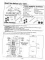
The installation,
STACKED WASHER/ DRYER
INSTALLATION INSTRUCTIONS
including
a proper
exhaust
system,
is the responsibility
of the owner.
LEAVE THESE INSTRUCTIONS WITH THE OWNER
Printed in U.S.A.
6 2708140-0498
Read this before you start...
• Teflon tape or pipe joint
compound (gas)
• Cutting knife
• Pipe wrench (gas)
•
•
•
•
Level
Screw driver (standard)
Duct tape
Crescentwrench
TOOLS
needed for
installation
• Ratchet
• 3/8" deep well socket
___,(_)_1
•• 5/16"
5/16" socket
nut driver
Electric Washer/Dryer Only
(electric- U.S. only)
Gas Washer/Dryer Only
ITEMS PROVIDED
0
Make sure you have everything necessaryfor proper installation.
1.
2.
3.
4.
GROUNDEDELECTRICAL OUTLET is required. See Electrical Requirementsstarting on page 6.
POWER CORDS for electric dryers (except Canada).
GAS LINES (if a gas dryer) must meet National and Local Codes.
EXHAUST SYSTEM- use rigid metal or flexible metal exhaust ducting. See Exhaust Requirementsin
this section.
5. UTILITIES SHUT OFFS (electric, gas and water) must be accessible after installation.
NOTE: Dryer door reversal instructions are on page 23 items 58 and 59.
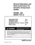
I,
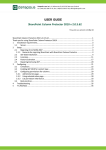
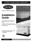
27V2"
69.9 cm
•I
27"
Location
of Canadian
terminal
block
_5/16"
2.4
Gas Manifold
Connection
Location
of Canadian
terminal
block
(electric
1 _8,:_,._
models)
.v _,.,}
/
_cationo
yer terminal
I,
block on electric models _'
and power supply cord _
(except Canadian)
on gas moaeJs
Dryer
___ L- 3/4"
I-tl.9 cm
_,'_
--,.
711/2"
81.6 cm
395/32"
washer drain hose
Washer
3/8"rain.
.95 cm
washer water
valve connections
Page 1
I
27 _/2"
69.9 cm
.
1_18"
2.9 cm
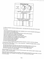
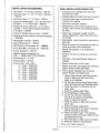
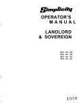
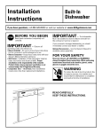
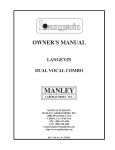
Exhaust Hood Type
90° Turns
4"
2-1/2"
Maximum length of 4-inch diameter
rigid metal duct
0
65 ft.
59 ft.
1
54 ft.
48 ft.
2
44 ft.
38 ft,
3
36 ft.
30 ft.
4
28 ft.
22 ft.
Maximum length of 4-inch diameter
flexible stiff wailed metal duct
0
36 ft.
28 ft.
1
32 ft.
24 ft.
2
28 ft.
20 ft.
3
25 ft.
17 ft.
4
23ft.
15ft.
For difficult installations requiring a flexible transition, multi-layeredthin foil exhaust duct may be used.
Thinfoil duct:
•
•
•
•
•
•
•
•
•
•
•
must be the type that is approved for dryer installations by ULor other comparabletesting agency.
must conform to all applicable codes.
must only be used as a transition between the dryer and the wall connection.
must not exceed 8 feet in length when stretched.
must not interconnectwith other thin foil flexible ducts.
must be extended to the full length with any excess removed.
must be installed only by a qualified and trained installer,
must not be placed near sharp objects.
must be kept as straight as possible.
must not be used inside the dryer.
must be inspected regularlyto be sure that it has not become crushed or otherwise restricted.
Thin foil duct will reduce airflow resulting in longer drying times. To reduce the negative effect on drying
performancethe thin foil ducting:
•
•
•
•
should be shaped such that there are no more than two 90-degree elbows in the foil duct.
should not be used in conjunction with rigid duct runs that are longer than 20 feet.
shouldnot be used in duct runs that include morethan three 90-degreeelbows.
should be supportedto minimize sagging.
Serious blockagecan result in flexible metal duct if bent too sharp. Never install any type of ducting in walls,
ceilings, or other concealedspaces.
Keep exhaust duct as straight and short as possible. Exhaust systems longer than recommendedcan extend
drying times, affect machine operation and may collect lint. Secure joints with duct tape.
Do not use screws.
Page 3
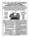
DO NOT exhaust dryer into any wall, ceiling, crawl space or a concealed space of a building, gas vent,
or any other common duct or chimney. This could create a fire hazardfrom lint expelled by the dryer.
The exhaust duct should end with an exhaust hood with a swing out damper to prevent backdrafts and entry
of wildlife. NEVER use an exhaust hood with a magnetic damper. The hood should have at least 12 inches
of clearance between the bottom of the hood and the ground or other obstruction. The hood opening should
point down. NEVER install a screen over the exhaust outlet.
When possible, do not exhaust the dryer directly into a window well in order to avoid lint build-up. Do not
exhaust under a house or porch.
If exhaust ductwork must run through an unheated area, the duct should be insulated and slope slightly down
towards the exhaust hood to reduce condensation and lint build-up.
If an existing exhaust system is to be used with your dryer(s) you must be sure:
•
•
•
•
•
The exhaust system meets all local, state and national codes.
That plastic flexible duct is not used.
To completely inspect and clean all lint accumulatingfrom the interior of the duct.
The duct is not kinked or crushed.
The exhaust hood damper opens and closes freely.
Inspect and clean the interior of the exhaust system at least twice a year. Disconnectelectric service prior to
cleaning. Check gas line on gas dryers anytime the dryer is moved.
Frequentlycheck to be sure the exhaust hood damper opens and closes freely.
WASHER REQUIREMENTS
Water pressure of 20 to 120 p.s.i, is requiredto correctly fill the washer to the proper levels.
DRAIN FACILITY
Recommendedheightof the stand pipe is 36 inches. If the stand pipe is less than 36 inches high, the drain
hose should be routed through the clip to raise the hose to the proper height. Stand pipe must be large
enough to accept the outside diameter of the drain hose.
Without the 36 inches high elevation, water may run out of the washer prematurely. Should the washer
fill and drain at the same time could indicatethat the drain hose has not been elevated to the proper height.
The drain hose is attached at the factory.
FLOORING
For best performance the washer must be installed on a solidly constructed floor. Wood floors may need to
be reinforcedto minimizevibration and/or unbalanced load situations. Carpeting and soft tile surfaces are
contributing factors in vibration and/or tendency for a washer to move slightly during the spin cycle. Never
install the washer on a platform or weak supportedstructure.
LOCATION CONSIDERATIONS
It is recommendedthe washer never be installed in areas where water may freeze since the washer will
always maintainsome water in the water valve, pump and hose areas. This can cause damage to belts,
pump, hoses and other components. Operatingtemperature should be above 60°F.
Page 4
GAS REQUIREMENTS
Use only Natural or LP (liquid propane) gases.
THE INSTALLATIONMUSTCONFORM WITH LOCAL CODES, OR IN THEABSENCE OF LOCALCODES,
WITH THE NATIONALFUELGAS CODE ANSI/Z223.1, LATESTREVISION (FOR THE UNITEDSTATES),
OR WITH THE CAN/CGA-B149INSTALLATIONCODES (FOR CANADA).
A gas dryer is equipped with a burner orifice for operation on NATURALgas. If the dryer is to be operated
on LP gas, it must be converted for safe and proper performanceand must be converted by a
qualified service technician. Conversion kits from NATURALto LP,or LP to NATURALare available
through your local dealer (see Accessories). If other conversions are required, check with the local gas utility
for specific informationconcerning conversion requirements.
Each dryer will provide an input of 22,000 B.T.U.per hour.
A 1/2 inch gas supply line is recommendedand must be reducedto connectto the 3/8 inch gas line on the
dryer.
The internal gas shut-off is accessed by removing the access panel on the dryer. The shut-off is positioned
for easy access near the gas valve.
The National Fuel Gas Code requires that an accessible, approved manual gas shut off valve be installed
within 6 feet of the dryer.
Additionally,a 1/8 inch N.P.T.(NationalPipe Thread) pluggedtapping, accessiblefor test gauge connection,
must be installed immediatelyupstream of the gas supply connectionto the dryer.
The dryer must be disconnectedfrom the gas supply pipingsystemduringany pressuretestingof thesystem.
DO NOT re-use old flexible metal gas line. Flexible gas line must be design certified by American Gas
Association (CGA in Canada). NOTE: Any pipe joint compound used must be resistant to the action of any
liquefied petroleumgas.
NOTE: As a courtesy, most local gas utilities will inspect a gas appliance installation.
GAS IGNITION The dryer use an automaticignition systemto ignitethe burner. There is no constant burning pilot.
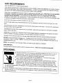
GROUNDING
• Improperconnectionof the equipment-groundingconductorcan result in a risk of
electricalshock. Check with a qualifiedelectricianor servicemanif you are in
• Do not modify the plug provided with the appliance- if it will not fit the outlet,
have a proper outletinstalledby a qualifiedelectrician.
• To prevent unnecessary risk of fire, electrical shock or personal injury, all wiring
and groundingmust be done in accordance with the National Electrical Code
ANSI/NFPA,No. 70-Latest Revision (for U.S.) or the Canadian Electrical code
I 1_0
I
doubt as to whether the applianceis properly grounded.
CSA C22.1-Latest Revision (for Canada) and local codes and ordinances. It is
the personal responsibilityand obligation of the applianceowner to provide adequate electrical services
for this appliance.
• All gas installations must be done in accordance with the National Fuel Gas Code ANSI/Z223.1-Latest
Revision (for the U.S.) or the CAN/CGA-B149Installation Codes-Latest Revision (for Canada) and local
codes and ordinances.
Page 5
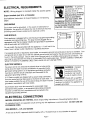
ELECTRICAL
REQUIREMENTS
WARNING- TOprevent
unnecessaryrisk of fire,
electrical shock or
personal injury,all wiring
and grounding must be
done in accordance
with local codes, with
the National Electrical Code,
ANSl/NFPA(for the United States)
or the Canadian Electrical Code
CSA C22.1 (for Canada).
NOTE: Wiring diagram is located inside the access panel,
Export models (not U.S. or Canada):
See Additional Instructionsfor Export Models on the following
pages,
GROUNDING
Eachdryer must be grounded. In the event of malfunctionor
breakdown,the ground will reduce the risk of electrical shock by
providing a path of least resistancefor electrical current.
Eachapplianceis equippedwith a cord havingan equipment-grounding
conductoranda groundingplug. The plug mustbe pluggedinto an
appropriateoutletthat is properlyinstalledandgroundedin accordance
with all localcodesand ordinances.
Do not modifythe plug providedwith the appliance- if it will not fit the
GAS MODELS
outlet,
have a proper outlet installed by a qualified electrician.
_
If a separateground is required by local codes, an accessory ground wire and ground clamp is available. Connect groundwire to back of unit with the cabinetground screw and washer the ground screw and washer ar
found in the parts package. Secure other end of groundwire to a suitableexternal ground connection. The
wire may be securedwith the clamp to a grounded COLD metal water pipe. NEVER CONNECTGROUND
WIRE TO PLASTIC PLUMBINGLINES, GAS LINES OR HOT WATER PIPES.
ELECTRIC MODELS
If a powercord is not used and the electric dryer is to be permanentlywired, the dryer must be connectedto a groundedmetal,
permanentwiring system; or an equipmentgroundingconductor
must be run with the circuit conductorsand connectedto the
equipmentgroundingterminal,
U.S. Electricmodelsare shippedwith a groundstrap connected
from the neutralterminal block post to the frame of each dryer. If
local codes prohibitsthe use of the ground strap,the dryer must be
groundedin accordancewith local codes,
Eachelectric dryer must be connectedto a groundedmetal,
permanentwiring system; or an equipmentgroundingconductor
must be run with the circuit conductorsand connectedto the
equipmentgroundingterminal.
WARNING: Improper
connectionof the
equipmentgrounding
conductorcan result in
a risk of electric shock.
Check with a qualified
electrician or servicemanif you are in
doubt as to whether the appliance is
properly grounded.
ELECTRICAL CONNECTIONS
BEFORE OPERATINGOR TESTING, follow all groundinginstructions in Grounding Section above.
An individual branch (or separate) circuit serving only this appliance is recommended. DO NOT USE AN
EXTENSIONCORD.
GAS MODELS - U.S. and Canada
A 120 volt,60 HzAC, approvedelectricalsupply,with a 15amperefuse or circuit breakeris required.
Page 6
ELECTRIC MODELS - U.S. and Canada
A 120/240volt, 60 HzAC approved electrical service fusedthrougha 30 amperefuse or circuit breakeron both
sides of the line is requiredfor the dryerand a 120volt 60 Hz AC approvedelectricalsupplywith a 15 ampere
fuse or circuitbreakerfor the washer.
If a powercord is used,the cord should be plugged into a 30 ampere receptacle.
U.S. ELECTRIC MODELS
The power cord is NOT provided with U.S. electric model dryers.
IMPORTANT: When permitted by local codes, the dryer electrical supply may be connected by means of a
new power supply cord kit, marked for use with clothes dryer, that is U.L. listed, rated at 120/240volts
minimum,30 amperes with three No. 10 copper wire conductors terminated with closed loop terminals,
open-end spade lugs with turned up ends or with tinned leads.
Do not reuse a power supply cord from an old dryer. The power cord electric supply wiring must be retained
at the dryer cabinet with a suitable UL listed strain relief.
If the dryer is to be installed in an area where local codes do not permit groundingthrough neutral, only a 4
conductor power cord, rated and terminatedas above, may be used.
120/208Volt Electrical Systems:
A U.S. electric washer/dryermust be converted if it is to operateon a 120/208volt electrical system. A heating
element conversionkit is availablefor the dryer along with a transformerfor the washer (seeAccessories).
CANADIAN ELECTRIC MODELS
All Canadian models are shipped with the power cord attached.
It is not permissible to convert a dryer in Canada to 208 volts,
Additional Instructions for Export Models
(not U.S. or Canada)
Contact the distributorthat sold the appliance or: Maytag International,8700 W. Bryn Mawr Avenue, Chicago,
Illinois USA 60631,773-714-0100, for informationon product, shipping damage, replacement parts and
accessories.
Maytagmodels manufacturedfor operation on 60 Hz AC are not designed for use on 50 Hz AC
electrical service and conversionof the product from 60 to 50 Hz operation is not recommended. For
additional informationon 50 Hz products,contact Maytag International.
The electric service requirementscan be found on the data label located on the front of the dryer behind the
door.
EXPORT ELECTRIC MODELS
Export electric models are manufacturedfor operation on either 230/240 volt, 50 Hz or 220 volt, 60 Hz
approved electric service. A two-wire approvedelectrical service with a 30 ampere fuse or circuit breakeris
required. The dryer must be properly groundedwith a ground wire.
IMPORTANT:When permitted by local codes, the dryer electrical supply may be connected by means of a
new power supply cord kit, marked for use with clothes dryers, that is agency listed, rated at 240 volts
minimum,30 amperes with two No. 10 copper wire conductors terminatedwith closed loop terminals,
open-end spade lugs with turned up ends or with tinned leads.
Do not reuse a power supply cord from an old dryer. The power cord or electric supply wiring must be
retained at the dryer cabinet with a suitable agency listed strain relief.
Page 7
ADDITIONALINFORMATION
REPLACEMENT PARTS AND ACCESSORIES
If the dryer requires replacement parts or accessories,contact your local Maytag dealer from whom you
purchased your appliance or:
Maytag Customer Service
240 Edwards Street, S.E.
Cleveland,Tennessee 37311
Phone 615-472-3333,for informationon the nearest authorized Maytag Parts Distributor.
EXPORT MODELS
Contact the Commercial Distributorfrom whom you purchasedyour applianceor:
Maytag International
8700 W. Bryn Mawr Avenue
Chicago, Illinois, USA 60631
Phone 312-714-0100,for informationon the nearest authorized Maytag Parts Distributor.
Page 8
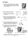
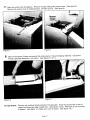
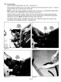
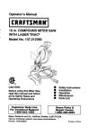
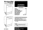
To install...
1• Carefully remove any packagingmaterials from the outside of the
washer. Set aside two corner posts for installation. IMPORTANT:
Noticethat the hoses and power cord are tied up with a shipping
strap. The strap should not be cut or removed until the machine
is ready to be installed.
Figure 1
2.
Lay two corner posts behind the washer and
gently tip the washer over on to its back.
_
___
-•
4L_____j..jiI if///
3. Using a screwdriver,pry off the crate bottom
wire retainers (2) and remove the crate bottom
from the washer.
Figure 2
4.
Figure 3
Locatetwo 1/2 inch hex shipping bolts on bottom of
metal base. Removeboth
bolts, freeing
suspension.
DO NOT BE ALARMED
as the tub
lastand
bolt
Shipping
Bolts
__
resting against the back of the washer.
is removed, the tub will jump to a positionwhere it is
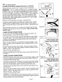
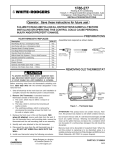
5.
6.
Loosenthe four adjustablewasher legs and lock nuts. Install
vinyl feet found in installationpackage. Feet can be more
easily installedwhen immersedin hot water before installing.
Carefully raise the washer back to an upright position.
_
Figure4
__'_
_--'---
At the installationsite, locatethe metal buckles attached to
the shippingstraps at back of washer. Carefully cut away
straps near both buckles,completely removingboth
buckles from the washer.
Figure6
Figure 7
Pull loose straps
from back of washer
one at a time until
all straps have been
removed.
Insert inlet hose screens in the ends of the hot and cold inlet hoses. Screens are found in the
miscellaneousparts package. Domed surface is to face the valve.
Page9
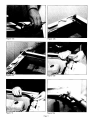
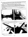
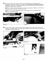
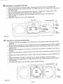
7, Open the washer door 90 degrees. Removethe tape holding the access cover. (See figure 8.)
Removethe access cover by sliding forward. DO NOT pull up. (See figure 9.)
Figure 8
Figure 9
8, Open the Accessory Carton and remove the access panel. Discardshipping materials. Gas dryers
include a gas pipe assembly in the carton. (See figures 10 & 11.)
Figure 10
Figure 11
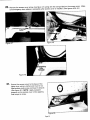
For Gas Dryers: Removered and blue thread protectors from gas pipe. Knock out square hole in rear of
support and insert gas pipe through hole. (See figures 12a-d.) Allow pipe to rest on inside
of support. (See figure 13.) Make sure valve is closed. (See figure 13a.)
Page 10
Figure 12a
Figure 12b
Figure 12c
Figure 12d
Figure 13
Figure 13a
Page 11
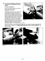
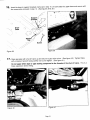
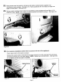
9. For nonalcove installations,
utilities and
venting can be connected after units are
stacked.
For alcove installations:
Securethe exhaust bracketto the rear of the
washerwith screwsprovided.
(See figures 14, 15& 16.)
Unsnaphosesfrom plastic hosecaddy,leaving
caddyattachedto the back of the cabinet.
Connectfill hoses to faucets (hotwater hose is
the left hose as you standfacing the front of the
washer). Insertthe drain hose in the stand pipe
recommendedheightof 36 inches,minimumof
24 inches. Note: If drain hose is not secure in
the standpipe, use a portionof the shipping
strapto securethe drain hose to the stand pipe.
Figure 14
Make sure that drain hose is securedto the hose
caddyafter installation. Fill hosesare not to
be securedto caddy. Turn on water and check for leaks.
Move unit into position,leveland tightenthe levelinglock nuts on the legs. Securethe vent pipe to the
exhaustbracket. (See figure 16.) MAKING SURE FIRST THAT OUTLET IS NOT ENERGIZED,plug
washer into outlet.
Figure 15
Figure 16
Page 12
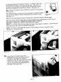
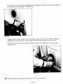
For gas dryers apply joint compound or about 1-1/2 wraps of Teflontape
over threaded connectionon the end of the gas pipe. (See figure 17.)
An elbow is recommended,for additionaldepth, pointing down to allow
the unit to be located further back into the alcove. (See figure 18.)
_
1
Note: Pipejoint compound must be resistant to the action of any liquefied
petroleum
gas.
Add additionalfitting
to connect the 3/8 inch gas pipe to a female threaded
end of a 3/4 inch flexible connector making sure the connection is tight.
(See figure 19.)
1
Figure 17
Make sure the shutoffvalve on the end of the gas pipe is closed and connectto the gas supply.
Open gas service valve and check all gas supply connections from service valve to shutoff valve for
leaks using a soap solution, DO NOT use an open flame to check for
gas leaks. If bubbles occur,tighten the connections and recheck.
NOTE: As a courtesy, many local gas utilities will inspect a gas appliance installation. Check with your
local utility to see if this service is provided in your area.
NOTE: The minimum permissible gas (natural or mixed) supply pressure for purposes of input
adjustment is 4.5 inches of water.
Figure 18
Figure 19
1 0, Lay the dryer on its side using 2 of the
cardboard corner posts to protect the side of
the cabinet. (See figure 20.) Remove
protective film from the control panel, and using
a 5/16 inch nut driver, remove the shipping
bolts (3) securing the wood shipping base to
the bottom of the upper dryer.
Figure 20
Page 13
11,
For gas dryers:
Removeyellow thread protector from union. (See figure 21.)
Positionthe dryer upright in front of the washer, with the rear of the dryer facing the washer. To prevent
damage to floors do not slide the dryer on the floor!
NOTE: For gas dryer alcove installation,plug powercord for dryer into an outlet MAKINGSURE FIRST
THATOUTLET IS NOT ENERGIZEDprior to lifting dryer onto washer.
Holdingthe base to support bracket, remove the 2 #10 hex head screws and base support brackets
(notehow the brackets are inserted) located at the front of the dryer base, marked with orange labels.
(See figures22 & 23.) NOTE: Brackets and screws will be used later.
A protectiveconduit (plastic) is provided for the power cord. Install the conduit over the power cord.
The conduit is slit to facilitate installation. (See figure 24.)
Yellow
Thread
Protector
Figure21
Hex
Head
Screw
Figure 22
Base
Su
Bracket
Figure23
Figure24
Page 14
Base
Bracket
TO MAKE ELECTRICALCONNECTIONFOR U.S. DRYERS
Reviewelectrical requirements on page 6 of these instructions.
12, For electric dryers:
I
CONNECTION. The dryer frame is grounded to the neutral conductor
at the terminal block. A 4-WIRE SYSTEMCONNECTIONis required
IMPORTANTAll U.S. models are produced
for a or
3-WIRE
for new or remodeledconstruction,mobile
homes,
if localSYSTEM
codes do /®l _er_
not permit groundingthrough neutral. If the 4-wire system is used,
_ _
the
dryerblock.
frame cannot
grounded
the neutral conductor
at the
terminal
Refer tobe
the
followingtoinstructionsfor
3- and 4-WIRE
SYSTEM CONNECTIONS.
Removethe terminal block cover plate. (See figure 25.)
A protective conduit (plastic)is providedfor the power cord. Cut the
conduit so that it is approximately18 inches shorterthan the power
cord and thread the power cord through the conduit. (See figures26 &
27.)
Insert the power cord with a U.L. listed strain relief through the hole
provided in the cabinet near the terminal block. Note, a strain relief
must be used.
3-WIRE SYSTEM CONNECTIONS
Do not loosenthe nuts already installed on the terminal block. Be
sure they are tight. Use a 3/8 inch deep nut driver.
If the power cord has terminals, place the terminals over the existing
nuts on the posts. The neutral (white or center wire on power cord)
conductormust always be connected to the center (silver colored)
post of the terminal block.
Secure in place using the nuts provided in the parts oackage. If the
power cord does not have terminals, use the cupped washers ahead
of the nuts.
Be sure the terminal block nuts are tight. Secure the power cord in
position. Tighten the strain relief screw(s) in order to clamp the strain
relief to the cord. (See figure 28.)
Replacethe terminal block cover.
BEFOREOPERATINGOR TESTING, follow the grounding directions
on page 5.
4-WIRE SYSTEM CONNECTIONS
Removethe ground strap screw from the terminal block support. Fold
the ground strap over so both ends of the ground strap are attached
to the center terminal block post.
Connectthe neutral (white)conductor of the cord to the center (silver)
post of the terminal block. Connectthe grounding (green) wire of the
cord to the terminal block support using the ground strap screw.
Connectthe red and black wires of the cord to the outer posts of the
I®
|
/,Figure 25
O
B
I
I
Figure 26
Figure27
3-Wire System with
Cord Attached
,__,,_Power
Ground
Neutral
Strain
relief
Figure 28
4-Wire System with
Power Supply Attached
Neutral
--
°
_
_.'_'_
terminal
Be sure the
block.
terminal block nuts are on tight. Secure the power cord in
Post ----. __/
positiOn.relief
Replacethe
to theTightencord,
terminal
the(seeStrainfigurerelief29.)screw(s)
block cover.
in order to clamp the strain
WARNING: If converting from 4-wire electrical systems to 3-wire, the
ground strap must be reconnectedto terminal block support to ground
the dryer frame to the neutral conductor.
•///__
Page 15
i
Folded
Ground
Strap
o _
(_
Figure 29
/e Neutral
Strain
Relief
4''/
2-WIRE AND GROUND SYSTEM CONNECTIONS
2-Wire and Ground System
Removethe terminalblockcoverplate.
Insertthe powercordwithan agencylistedstrainrelief
throughthe hole providedin the cabinetneartheterminal
block. Note,a strainreliefmustbe used.
Do notloosenthe nutsalreadyinstalledonthe terminal
block. Be suretheyare tight. Use a 3/8 inchdeep well
socket.
("
_
_
o
__
Neutral
Post"
o
Power
Cord
Ground
o
support using the ground screw. (See figure 30.)
If the power cord has terminals, place the terminals over
Secure the power cord ground wireto the terminal block
the existing nuts on the posts. The neutral wire in power
cord must be connected to the center (silver colored
post of the terminal block.
Secure in place using the nuts provided in the parts
_;Je
Power
cord
Neutral
use the cuppedwashers ahead of the nuts.
package. If the power cord does not have terminals
Be sure the terminal block nuts are tight. Secure the
power cord in position. Tighten the strain relief screw(s)
in order to clamp the strain reliefto the cord.
,Wire
o
f-_
_. • and
(" Ah JF"/strain
f
Figure 30
relief
Replace the terminal block cover.
BEFORE OPERATINGOR TESTING, be sure the machine is properly grounded.
EXPORT GAS MODELS
Export gas models are manufacturedfor operation on either 230/240 volt, 50 Hz or 220 volt, 60 Hz AC
approved electrical service with a 15 ampere fuse or circuit breaker.
Export gas models have been manufacturedfor use with natural gas having a higher heatingvalue of approximately 1025 BTU per cubic foot. Conversion to LP gas with a higher heating value of approximately2500
BTU per cubic foot must be performed by a qualified service technician. A conversion kit is available.
For electric dryers in alcove installation:
MAKING SURE FIRST THAT OUTLET IS NOT ENERGIZED,plugpowercordfor dryerintoan outletpriorto
lifting dryer ontowasher.
13. Make sure that the exhaust seal is in place and even with the end of the exhaust pipe.
(See figures 31 & 32.)
Figure 31
Figure 32
Figure 33
Make sure front tabs are not bent, use screwdriverto straightentabs if bent. (See figure 33.)
Page 16
1 4, Two people,one on each side, grasp and lift the dryer onto the washer (see figure 34), taking care not to
bend the tabs located towards the front of the washer. Slide the upper dryer towardthe rear makingsure
that the guides fall between the rails on the support of the washer. (See figure 35.)
WARNING: Make sure POWERIS NOT SUPPLIEDTO OUTLET during installation.
When placing the dryer onto the washer, make sure the POWER CORD IS NOT PINCHED between
the washer and the dryer or between the exhaust pipe and bracket. If the dryer cannot be pushed all
the way back, check to see if the power cord is being pinched between the back of the dryer and the
exhaust bracket.
Make sure that SHUT-OFF FOR UTILITIES(electric, gas and water) WILL BE ACCESSIBLE after the
applianceis installed.
Figure 34
Figure 35
15.Check to make sure the tabs on the washer are engaged in slots at the front of the base of the dryer.
(See figures36 & 37 - some components removed for clarity.)
Front Right
Dryer
Base
O
Figure36
Figure 37
Rotateforward to check engagement.
Page 17
16. Insert the base to support brackets
(removed in step 11) on both sides the upper base and secure with
the screws also removed in step 12. (See figures 38 & 39.)
....
"
_"
o pp
L'u--or"
\\\
\\
Dryer
Base
"/
_\_- -\ _
Tab
....
, _;
/_
Screw
,\
Figure 38
Figure 39
17. Raise gas pipe with shut off valve up and secure to gas valve union•
(See figure 40.) Tighten fitting
with a crescent wrench being careful not to over tighten. (See figure 41.)
Do not apply teflon tape or pipe sealing compound to the threads of the shut off valve. This is a
brass expansion sleeve fitting.
Figure 40
Figure 41
Page18
18.Open the gas shut off valve inside the upper dryer (see figures 42 & 43), and check the union
connectionto the gas valve for leaks using a soap solution, DO NOT use an open flame to check for
gas leaks. If bubbles occur,tighten the connections and recheck. Make sure not to let solution drip
into any electrical connector or component.
NOTE: As a courtesy, many local gas utilities will inspect a gas appliance installation. Check with your
local utilityto see if this service is provided in your area.
NOTE: The minimum permissible gas (naturalor mixed)supply pressure for purposes of input
adjustment is 4.5 inches of water.
Figure42
Figure43
19. Removewire harnesses and plastic clips from base (see figure 44) and connect each harnessto the
connector in the washer making sure locking tabs are engaged, and harness is tucked out of the way of
the dispenser. (See figures 45 & 46.)
Figure 45
7
ii_i ii
Figure 44
L
Figure 46
Page 19
20,
Removethe access cover screw (see figure 47), alongwith the orange label on the accesscover. Make
sure emergencydoor release is accessible after access cover is installed (See figures48 & 49.)
m
Figure47
Figure48
Figure 49
21• Secure the access cover to the base of the
_"
upper dryer using a ratchet and the #10 hex
head access cover screw removed in step 20.
(See figure 50.) NOTE: Apply rearward
pressure on the access cover while applying
final torque to screw.
Figure 50
Page 20
22. Rotate access panel into position, and securewith white or almond screws supplied in the
miscellaneousparts package. (See figure 51.) Removeprotective film from fascia and tape from
edges of control panel. (See figure 52.)
23. Removewasher and dryer timer knobs from miscellaneous parts package and insert them on the
respectiveshafts. NOTE: Timer shafts are different between the washer and dryer. (See figure 53.)
.....
!
Figure 51
Figure 53
Figure 52
24. For nonalcove installations
(where there is access to the rear of the appliance):
Plug in powercordforthe washer and dryer.
Removethe 2 outerscrews in the back of the cabinetclosestto the sides (see figure 54) and secure
the securitybrackets(2) to the upper cabinet. NOTE: Slottedhole is orienteddown. (See figure 55.)
Do nottightenuntilthe next step is completed.
Cabinet Screw
Figure 54
Cabinet
Screw
Figure55
Page 21
Secure the other ends of the security brackets (2) to the support using #10 hex head screws provided in
the miscellaneous parts package. (See figure 56.)
i
Figure 56
If appliance has not been leveled, move it into position, check it with a level and make the necessary
adjustmentsto the leveling legs. Once level, tighten the leveling leg locking nuts with a wrench.
Connectthe exhaust ducts to duct work by insertingthe elbow while holding onto the exhaust seal.
(See figure 57.)
Figure 57
25.
Removethe tape and cardboard protection for the door on the lower dryer.
Page 22
26. Directions for reversingthe dryer door:
1. Removethe hinge hole covers and screws. Move the door catch cover to the oppositeside.
2. While supportingthe door, remove 4 screws in the hinges that secure the hinges to the cabinet and
set the door down.
3. Move the following parts to the opposite side of the door: 2 hinges and 4 hinge screws, 4 door
screws, door strike and screw, inner door cover plate and screw.
4. Attach the door to the opposite side of the cabinet using the 2 counter sunk hinge screws.
(See figure 58.)
5. Replace the hinge hole coversto the opposite side.
Door Catch
.-" ....
"-.
/"
_
_',
Figure 58
'
_"
"
•
Counter Sunk Screw
I
"",
t
_,,
_
Door
%-- Screws
str,
ka
I 1
x
.---22-222222-222J
'_,,"
Cover
Coy
,
_+
--uoor
_ Screws
_/[/
27. Directions for reversing the washer door:
1. Swing door fully open and support it while removing four hingescrews (which hold hinges to door
assembly).
2. Set door asideand transferfour color matcheddoor screws to the oppositeside of the door assembly.
3. Remove one screw holding top hinge to cabinet and one screw holding top hingecover to cabinet
(oppositeside).
4. Remove hinge and bracketfrom cabinet by moving them up and down to a positionwhere they are
released.
5. Install hinge and bracket in swapped locations and drive screws to attach them securelyto the cabinet.
6. Comparetop hinge and top bracketto bottom hinge and bottom bracket for correct assembly position.
7. Repeat procedures4 through 6 for bottom hinge to cabinet and bottom bracket to cabinet.
8. Support door in fully open position on hinge side and drive four screws to secure attach hinges to
door assembly.
9. Close door and check to see that clothes washer operates properly.
Counter Sunk Screw_,
//
/ /
'/"_"
f
Door
Screws
_1
It
7it
I_t
Hole
Covers
,,,,!,\_
......
"-_.!,\.,..___ _ _ .. /
I
ng
+++
_
_
Figure 59
Page 23
_ "_+ _'
_
Door
Screws
INSTALLATION ACCESSORIES
•Vent hood - 4" (10.16cm) opening- 059129
• Aluminum pipe - 4" x 24" (10.16cm x 60.96cm)
- 059130
• Aluminum elbow - 4" (10.16cm)- 059131
• Aluminum window plate - 15" x 20" (38.10cm x
50.80cm) -4" (10.16cm) hole- 059134
• Flexible aluminum vent duct - 4" (10.16cm)
diameter - 38" (81.28cm)length stretches to
8' (2.44cm) 304353
• Clamp for flexible aluminum duct - 304630
• Exhaust duct kit for base or left side exhausting
- 33001881
• Rectangularvent kits - 059144
• Back draft damper 4"- 059146
30619_
• NATURALto LP conversion kit
FINAL INSTALLATION CHECK LIST
_ Instruction and Installation Kit have been
removed from dryer.
[] Shippingbolts and strapshave been removed.
[] Assurethat the dryer is slid back and is
securedto the washer.
[] Vinyl feet have been installed.
[] Washer/dryeris level with all legs firmly on
the floor, with the lock nuts tightened against
the base.
_ Drain hose is properly located into drain
facility, snapped into drain hose strap and is
nbt kinked.
[] Gas Models- gas is turned on, there are no
gas leaks.
[] Water
turned
and connections.
checked for leaks at
faucet is
and
wateron
valve
i
- LP to NATURALconversion kit - 33001287
• Anchor bracket kit - 303740
C] Washer fills properly on all temperature
selections.
_i
i_
ll
!t
• Heatingelement conversion kit,
208 v., - 308590 (NOT FOR CANADA)
• Grounding wire - 311155
• Ground clamp - 301548
_ Exhaust duct work is hooked up and joints
taped.
[] Use rigid or stiff walled flexible metal vent
material.
i!
I_
• Powercords - 240 v, 30 A
4' - 3-wire- 33001780
5' - 3-wire - 33001822
6'- 3-wire - 33001823
10' - 3-wire - 33001838
4' - 4-wire - 33001781
6' - 4-wire - 33001824
[] Plastic flexible duct is NOT used.
[] Washer and dryer are plugged into electrical
outlet and are properly grounded.
[] Test for proper operation by running the
washer through a complete cycle.
i
'_
_
! , _
,_
i
ii
'
!
_:
....
ii
i,
i!
n
6'-4-wire-
1. Select Cotton/Sturdy,Hot/Cold and Max
Extract. Make sure the Extra Rinse
option is not selected.
2. Set the timer into the Heavy-Normal-Light
wash band and press the Start/Stopbutton.
3. Verify the washer is filling from the hot
water valve.
4. Verify the washer stops filling.
5. Push Start/Stop to stop washer.
6. Set the timer into the Final Rinse
increment and press the Start/Stop
button to restart the washer.
7. Verifythe washer is filing from the cold
water valve.
8. Verify the washer stops filling.
9. Wait 30 seconds for the timer to advance
itself one increment into Spin.
10. Verify the washer spins. This will take
several minutes as the door needsto lock
and distribute the load.
_11. Pull on the doorto make sure it has locked.
12. Reset the washer to start position.
[] Dryer runs, heats,shuts off.
33001825
Page 24